Embed Size (px)
Citation preview

5 Port Solenoid Valve
F T
L S
SeriesAverage
speed(mm/s)
ø40 ø50 ø60 ø80 ø100 ø125 ø140 ø160 ø180 ø200
Series MB, CA1Pressure 0.5 MPaLoad rate: 50%Stroke 500 mm
Series CS1Pressure 0.5 MPaLoad rate: 50%Stroke 1000 mm
11001000900800700600500400300200100
0
Bore size
Speed controller
AS420-03
Silencer
AN300-03
SPG (Steel pipe) dia. x Length
10A x 1m
C
P.766 P.770
P.774
P.788
P.778
Metal seal Rubber Seal
Space-saving profile
Space-saving —— 40% less
Capacity-saving — 50% less
(In-house comparison)
Clean space-saving design with all pilot valves concentrated to one side with no protrusions in any direction
Compact with largeflow capacity(Ideal for driving cylindersup to ø140)
Outstanding response times and long service life
A variety of common wiring methods are standardized.<Plug-in type>
Built-in One-touch fittingsfor easier piping
Enclosure IP65 compliantDusttight/Low jetproof type
(Metal seal with indicator light/surgesuppressor)
100 million cycles
Accuracy ±3 mS
∗ According to SMC life testconditions
VQ4100 17 mS(Single)
VQ4200 12 mS(Double)
Cylinder Speed ChartUse as a guide for selection.Please confirm the actual conditions with SMC Sizing Program.
Perpendicular, upward actuation
Horizontal actuation
∗ It is when the cylinder is extending that is meter-out controlled by speed controller which is directly connected with cylinder, and its needle valve with being fully open.
∗ The average velocity of the cylinder is what the stroke is divided by the total stroke time.∗ Load factor:((Load weight x 9.8)/Theoretical force) x 100%
System Components
kit(D-sub connector)
kit(Terminal block box)
IP65 compatibleEnclosure
kit(Serial transmission)
IP65 compatibleEnclosure
kit(Lead wire)
IP65 compatibleEnclosure
Individual wiring type<Plug lead type>
kit(Connector)
IP65 compatibleEnclosure
Grommet type
VQ4100--03VQ4101--03
759
Series VQ4000
SJ
SY
SV
SYJ
SZ
VP4
S0700
VQ
VQ4
VQ5
VQC
VQZ
SQ
VFS
VFR
VQ7
P0759-P0850-E.qxd 08.9.1 2:58 PM Page 759
Courtesy of Steven Engineering, Inc.-230 Ryan Way, South San Francisco, CA 94080-6370-Main Office: (650) 588-9200-Outside Local Area: (800) 258-9200-www.stevenengineering.com

Model
Series Configuration
VQ4000 Rc 3/8
ModelP
ort s
ize Flow characteristics Response time (ms)
Standard 1 W
ACLow wattage 0.5 Wb CV b CV
SingleVQ41 0
VQ41 1
VQ42 0
VQ42 1
VQ43 0
VQ43 1
VQ44 0
VQ44 1
VQ45 0
VQ45 1
VQ46 0
VQ46 1
Double
Closed center
Exhaust center
Pressure center
Double check
05
Standard SpecificationsValve construction
Fluid
Maximum operating pressure (3)
Ambient and fluid temperature
Lubrication
Manual override
Shock/Vibration resistance
Enclosure
Coil rated voltage
Allowable voltage fluctuation
Coil insulation type
Min. operatingpressure
Single
Double
3 position
Metal seal
Air/Inert gas
Rubber seal
Air/Inert gas
0.15 MPa
0.15 MPa
0.15 MPa
–10 to 50°C
0.20 MPa
0.15 MPa
0.20 MPa
–5 to 50°C
1.0 MPa (0.7 MPa)
JIS Symbol
2 position single
2 position double (Metal)
2 position double (Rubber)
(A) 4
(B)2
1(P)
5(R1)
3 (R2)
(A) 4
(B)2
1(P)
5(R1)
3 (R2)
(A) 4
(B)2
1(P)
5(R1)
3 (R2)
3 position closed center
3 position exhaust center
3 position pressure center
(A) 4
(B)2
1(P)
5(R1)
3 (R2)
(A) 4
(B)2
1(P)
5(R1)
3 (R2)
(A) 4
(B)2
1(P)
5(R1)
3 (R2)
3 position double check
1(P)
5(R1)
3 (R2)
(A)4
(B)2
Metal seal
Rubber seal
Metal seal
Rubber seal
Metal seal
Rubber seal
Metal seal
Rubber seal
Metal seal
Rubber seal
Metal seal
Rubber seal
20 or less
25 or less
12 or less
15 or less
45 or less
50 or less
45 or less
50 or less
45 or less
50 or less
55 or less
62 or less
6.2
7.2
6.2
7.2
5.9
7.0
6.2
7.0
6.2
7.0
2.7
2.8
0.19
0.43
0.19
0.43
0.23
0.34
0.18
0.38
0.18
0.38
—
—
1.5
2.1
1.5
2.1
1.5
1.9
1.5
1.9
1.6
1.9
—
—
6.9
7.3
6.9
7.3
6.3
6.4
6.9
7.3
6.4
7.1
3.7
3.9
0.17
0.38
0.17
0.38
0.18
0.42
0.17
0.38
0.18
0.38
—
—
1.7
2.0
1.7
2.0
1.6
1.9
1.7
2.0
1.6
2.0
—
—
05
05
05
05
05
05
05
05
05
05
05
22 or less
27 or less
14 or less
17 or less
47 or less
52 or less
47 or less
52 or less
47 or less
52 or less
57 or less
64 or less
22 or less
27 or less
14 or less
17 or less
47 or less
52 or less
47 or less
52 or less
47 or less
52 or less
57 or less
64 or less
0.23(0.29)
0.26(0.32)
0.28(0.34)
0.28(0.34)
0.28(0.34)
0.50(0.56)
Mass(kg)1 4/2 (P A/B) 4/2 5/3 (A/B EA/EB)
C [dm3/(s•bar)]C [dm3/(s•bar)]
2 po
sitio
n3
posi
tion
Note 1) Value for valve on sub-plate and cylinder port Rc 3/8Note 2) Based on JIS B 8375-1981 Supply pressure: 0.5 MPa, with indicator light and surge voltage
suppressor, clean air. This will change depending on pressure and air quality.) The value when ON for the double type.
Note 3) Values inside ( ) indicate the weight of plug lead units.Table: Without sub-plate, With sub-plate: Add 0.41 kg for plug-in type,0.30 kg for plug lead type.
Plug-in unit
Plug lead unit
Val
ve s
pec
ific
atio
ns
So
len
oid
sp
ecif
icat
ion
s
Power consumption(Current)
24 VDC
12 VDC
100 VAC
110 VAC
200 VAC
220 VAC
(1)(1)
Note 1) Use dry air to prevent condensation when operating at low temperatures.Note 2) Impact resistance: No malfunction occurred when it is tested with a drop tester in the axial
direction and at the right angles to the main valve and armature in both energized and de-energized states every once for each condition. (Values at the initial period)
Vibration resistance: No malfunction occurred in a one-sweep test between 45 and 2000 Hz. Test was performed at both energized and de-energized states in the axial direction and at the right angles to the main valve and armature. (Values at the initial period)
Note 3) Values inside ( ) denote the low wattage (0.5 W) specifications.
760
Base MountedPlug-in/Plug Lead Single Unit
Series VQ4000
Not required
Push type/Locking type (Tool required) Option
150/30 m/s2
Dust tight (IP65 compatible)
12, 24 VDC, 100, 110, 200, 220 VAC (50/60 Hz)
±10% of rated voltage
Class B or equivalent
1 W DC (42 mA), 0.5 W DC (21 mA)
1 W DC (83 mA), 0.5 W DC (42 mA)
Inrush 1.2 VA (12 mA), Holding 1.2 VA (12 mA)
Inrush 1.3 VA (11.7 mA), Holding 1.3 VA (11.7 mA)
Inrush 2.4 VA (12 mA), Holding 2.4 VA (12 mA)
Inrush 2.6 VA (11.7 mA), Holding 2.6 VA (11.7 mA)
P0759-P0850-E.qxd 08.9.1 2:58 PM Page 760
Courtesy of Steven Engineering, Inc.-230 Ryan Way, South San Francisco, CA 94080-6370-Main Office: (650) 588-9200-Outside Local Area: (800) 258-9200-www.stevenengineering.com

Seal
1
01
Metal sealRubber seal
VQ4
Body
5
Electrical entry
2
Type of actuation
Manual override
0VQ4 01Plug-in
Plug lead
Body
0: Plug-in sub-plate
Porting specificationsNilB
Side portedBottom ported
Port size
NilWithout sub-plate
(For manifold)
EnclosureNil Dust-protected
Dusttight/Low jetproof type
(IP65)W
Nil: Non-lockingpush type(Tool required)
B: Slotted locking type(Tool required)
Light/Surge voltage suppressorNilE
YesWithout light, with surge voltage suppressor
0203
Rc 1/4Rc 3/8
G
Lead wire length 0.6 m
H
Coil voltage
31
4
2
5
5: Plug lead sub-plate
123456
Lead wire length 1.5 m
FunctionNilY (1)
R (2)
Standard type (1 W)Low wattage type (0.5 W)
External pilot
VQ4000
Port size0203
Rc 1/4Rc 3/8Porting
specificationsNilB
Side ported Bottom ported (1)
EnclosureNilW
Dust-protectedDusttight /Low jetproof type
Electrical entryPS
Plug-in conduit terminalPlug lead
2 position single 3 position closed center
2 position double 3 position exhaust center
2 position double 3 position pressure center
(A) 4
(B)2
1(P)
5(R1)
3(R2)
1(P)
5(R1)
3 (R2)
(A) 4
(B)2
(A) 4
(B)2
1(P)
5(R1)
3(R2)
(A) 4
(B)2
1(P)
5(R1)
3(R2)
(A) 4
(B)2
1(P)
5(R1)
3(R2)
(A) 4
(B)2
1(P)
5(R1)
3(R2)
6
3 position double check
1(P)
5(R1)
3(R2)
(A)4
(B)2
How to Order Valves
How to Order Sub-plates
Met
alR
ubbe
r
Note)
Note) For double check style, refer to page 792.
Note) For thread standard, refer to page 795.
Gro
mm
et100 VAC (50/60 Hz)200 VAC (50/60 Hz)110 VAC (50/60 Hz)220 VAC (50/60 Hz)
24 VDC12 VDC
Applicable to DC specifications. Please select when you expect to energize the unit for extended periods of time. Refer to page 3 for details.For external pilot specifications, refer to page 795. Combination of external pilot and perfect interface is not possible.When two or more symbols are specified, indicate them alphabetically.
Note 1)
Note 2)
Note 3)
Note)
Note) It is not necessary for plug lead type.
Note 1) For bottom ported port size is RC 1/4 only.
Note 2) For thread standard, refer to page 795.
Replacement of pilot valve assembly (Voltage)• Refer to pages 800 and 801 for pilot
valve assembly part numbers.• For “How to Replace”, refer to page
805.
761
Plug-in/Plug Lead: Single Unit Series VQ4000Base Mounted
[Option]
[Option]
CE-compliantNil —
CE-compliantQ
CE-compliantNil —
CE-compliantQ
SJ
SY
SV
SYJ
SZ
VP4
S0700
VQ
VQ4
VQ5
VQC
VQZ
SQ
VFS
VFR
VQ7
VQ4000.qxd 10.11.25 9:47 AM Page 1
Courtesy of Steven Engineering, Inc.-230 Ryan Way, South San Francisco, CA 94080-6370-Main Office: (650) 588-9200-Outside Local Area: (800) 258-9200-www.stevenengineering.com

Conduit terminal
11 (12.5) 11 (12.5)
5090108
158
3824.6
48
19.5(21)
23.523.5
50158
10.511
38 48
5 x Rc 1/4,3/8 (5(R1), 3(R2) port Rc 1/4)
15.5
19.5
31
(21)
R1
PE
14
30
14.5
31
R2 27 30.5
32 41.5
79
12
45
27
SMC
13.513.5
30 45
5090
108
38 48
24.6
167 181
31G 1/2Electrical entry
Rc 1/8PE port
15.5
R1
19.5(21)
PE
14
30
31
27
Rc 1/8 External pilot port
R2
14.5
19.5(21)
41.5
3230
.5
79
12
45
Indicator light
Manual override
2 x ø5.6Mounting hole
Indicator light
Manual override
2 x ø5.6Mounting hole
59 73
5 1 3
4 2
A
X
P
5
4 2
3
5 31
4 2
X
P
A
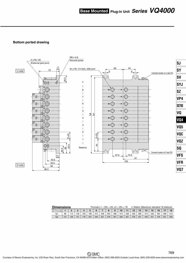
Bottom ported drawing
5 x Rc 1/4, 3/81(P), 4(A), 2(B), 5(R1), 3(R2) port
Rc 1/8 External pilot portRc 1/8
PE port
G 1/2Electrical entry
9
AB
1
AB B
R1
X
R2
14 12
181108 73
90 50
Indicator light
Manual override30 45
2 x ø5.6Mounting hole
24.6
38 48
15 3
G 1/2Electrical entry
15.5 P
Rc 1/8PE port
19.5(21)
19.5(21)
31 31
5 x Rc 1/4, 3/81(P), 4(A), 2(B), 5(R1), 3(R2) port5 x Rc 1/4, 3/8
1(P), 4(A), 2(B), 5(R1), 3(R2) port
14.5 27 30
.532 41
.591
.512
9
A
B
24
PE
2 x ø5.6Mounting hole
11(12.5)4(A) port
11(12.5)4(A) port
11(12.5) 2(B) port
11(12.5)2(B) port
Plug-in Type
2 position single: VQ410 -01
4(A) port 2(B) port
4(A
), 2(
B) p
ort
( ): Rc 3/8
2 position double: VQ420 -3 position closed center: VQ430 -3 position exhaust center: VQ440 -3 position pressure center: VQ450 -
01
01
01
01
3 position double check: VQ460 -01
: 3 position( ): Rc 3/8
762
Series VQ4000
P0759-P0850-E.qxd 08.9.1 2:58 PM Page 762
Courtesy of Steven Engineering, Inc.-230 Ryan Way, South San Francisco, CA 94080-6370-Main Office: (650) 588-9200-Outside Local Area: (800) 258-9200-www.stevenengineering.com

50
38
24.6 48
105.542.5
155.5
23.523.5
13.5
45
50
10.511
38 48
105.5155.5
42.5
R1
14
R2
19.519.5
3131
(21) (21)
PE
14.5
27 32 41.5
79
30.5
12
30 45
SMC
13.5
30
50
45
38 48
24.6
59 7342.5
105.5
164.5 178.5
3131
19.519.5(21) (21)
R1
PE
14
30
14.5
R2
27 32 41.5
30.5
79
12
Indicator light
2 x ø5.6Mounting hole
1
4 2
35
A
5
4 2
3
Bottom ported drawing
2 x ø5.6Mounting hole
27P
X
Rc 1/8 External pilot portRc 1/8
PE port
35 1
4 2
2 x ø5.6Mounting hole
Indicator light
X
P
Rc 1/8 External pilot port
Rc 1/8PE port
A
AB
9
AB
1
B
R1
PE
R2
14 12
178.5105.5 73
42.5 50
2 x ø5.6Mounting hole
24.6
38 48
5 31
A
Rc 1/8PE port
19.5(21)
19.5(21)
31 31
14.5 27 30
.5 32 41.5
91.5
129
P
X
24
B
30 45
11 (12.5) 11 (12.5)
5 x Rc 1/4, 3/8 (5(R1), 3(R2) port Rc 1/4)
5 x Rc 1/4, 3/81(P), 4(A), 2(B), 5(R1), 3(R2) port
5 x Rc 1/4, 3/81(P), 4(A), 2(B), 5(R1), 3(R2) port
11(12.5)4(A) port
11(12.5)2(B) port
5 x Rc 1/4, 3/81(P), 4(A), 2(B), 5(R1), 3(R2) port
11(12.5)4(A) port
11(12.5)2(B) port
Plug Lead Type
Grommet
2 position single: VQ415 -01
GH
4(A) port 2(B) port
Manual override
(A, B
por
t)
( ): Rc 3/8
2 position double: VQ425 -3 position closed center: VQ435 -3 position exhaust center: VQ445 -3 position pressure center: VQ455 -
01
01
01
01
GH
GH
GH
GH
Manual override
3 position double check: VQ465 01
Indicator light
Manual override
: 3 position( ): Rc 3/8
763
Plug-in/Plug Lead: Single Unit Series VQ4000Base Mounted
SJ
SY
SV
SYJ
SZ
VP4
S0700
VQ
VQ4
VQ5
VQC
VQZ
SQ
VFS
VFR
VQ7
P0759-P0850-E.qxd 08.9.1 2:58 PM Page 763
Courtesy of Steven Engineering, Inc.-230 Ryan Way, South San Francisco, CA 94080-6370-Main Office: (650) 588-9200-Outside Local Area: (800) 258-9200-www.stevenengineering.com

CD (2)
CU (2)
K (3)
NSB
SD (2)
SU (2)
W
Option
08 K
Manifold
1
1 Plug-in unit
01 1 station
Stations
VV5QSeries
4
4 VQ4000
C8 F U1
Cylinder portC6C8C10C120203B
CM
Control unit
Kit/Electrical entry/Cable length
F T
L S
Connector entry direction
D side U sideD0D1D2D3
U0U1U2U3
KitF
KitF
D0D1D2
U0U1U2
KitL
KitL SD S
TD TO
Without SI unitNKE Corp.: Uni-wire SystemNKE Corp.: Uni-wire H SystemSUNX Corp.: S-LINK System (16 output points)SUNX Corp.: S-LINK System (8 output points)DeviceNetOMRON Corp.: CompoBus/S System (16 output points)OMRON Corp.: CompoBus/S System (8 output points)CC-Link
D side U side
SymbolNil
Base MountedPlug-in Unit
Series VQ4000How to Order Manifold
•••
•••
The maximum and minimum number of stations are varieddepending on kit.(Refer to the table below.)
With One-touch fitting for ø6With One-touch fitting for ø8With One-touch fitting for ø10With One-touch fitting for ø12
Rc 1/4Rc 3/8
Bottom ported Rc 1/4
Mixed
Note) Shown VV5Q41-05C12FD0
Kit type
Refer to pages 796 to 799.
OptionNone
Exhaust cleaner: For D side mountingExhaust cleaner: For U side mounting
Special wiring specifications (Except double wiring)Name plate (T kit only)
Direct exhaust with silencer box: Exhaust from both sides (F/L kits only)Direct exhaust with silencer box: D side exhaustDirect exhaust with silencer box: U side exhaust
Enclosure IP65 (Except F kit)
Note 1) When two or more symbols are specified, indicate them alphabetically.Example) -CDK
Note 2) Combination of [C ] and [S ] is not possible.Note 3) Specify the wiring specifications on the
manifold specification sheet. (Except L kit)
UD
UD
kit(D-sub connector)
kit(Terminal block box kit)
kit(Lead wire cable)
kit(Serial transmission unit)
Without cableCable length 1.5 m Cable length 3 mCable length 5 m
1 to 18 stations
Terminal block mounting position
Terminal block box
IP65 compatible
3 to 18 stations
Electrical entryD side U side
Cable length 0.6 mCable length 1.5 m Cable length 3 m
1 to 16 stations
IP65 compatible
Unitmounting position
The valve is equipped with a lamp/surge suppressor, and the voltage is 24 VDC.
IP65 compatible∗ Applicable to INPUT
and OUTPUT type.D
sideU
side
3 to
18 s
tatio
ns N
ote)
Note) Add 2 stations for SI unit mounting. Maximum stations are 18. 2 stations are used for SI unit mounting.
Simple specials are available with SMC Simple Special System. For details about applicable models, refer to front matter 53.
Indicator lightManual override
External pilotsupply port
R1 port A, B port
P port
R2 port
Type of connection
∗ For INPUT and OUTPUT type, refer to pages 782 to 785.
CE-compliantNil —
CE-compliant
[Option]
Q
0F1HJ1J2QR1R2V
CE-compliant
764
VQ4000.qxd 10.11.25 9:47 AM Page 2
Courtesy of Steven Engineering, Inc.-230 Ryan Way, South San Francisco, CA 94080-6370-Main Office: (650) 588-9200-Outside Local Area: (800) 258-9200-www.stevenengineering.com

Manifold Specifications
VQ4000
Series Base model Type of connection
Porting specifications
1(P), 5(R1), 3(R2) 4(A), 2(B)
Side
Bottom Rc 1/4
F, L kit:0.32n+0.75
S, T kit:0.32(n–2)+1. 8
Flow Characteristics at the Number of Manifold Stations (Operated individually)
Manifold Option
Model
C [dm3/(s·bar)]
b
Cv
C [dm3/(s·bar)]
b
Cv
C [dm3/(s·bar)]
b
Cv
C [dm3/(s·bar)]
b
Cv
5.9
0.23
1.5
6.2
0.19
1.5
6.8
0.31
1.8
7.0
0.38
1.9
5.9
0.23
1.5
6.2
0.19
1.5
6.8
0.31
1.8
7.0
0.38
1.9
5.9
0.23
1.5
6.2
0.19
1.5
6.8
0.31
1.8
7.0
0.38
1.9
5.9
0.23
1.5
6.2
0.19
1.5
6.8
0.31
1.8
7.0
0.38
1.9
Passage/Stations Station 1 Station 5 Station 10 Station 15
4(A), 2(B)port
location
Port size Note)Maximum applicable
stations
Applicable solenoid
valve
VV5Q41-
F kit–D-sub connector T kit–Terminal block box L kit–Lead wire S kit–Serial transmission
Rc 1/2Option
Direct exhaustwith
silencer box
C6 (For ø6)C8 (For ø8)
C10 (For ø10)C12 (For ø12)
Rc 1/4Rc 3/8
F, T kit18 stations
L kit16 stations
S kit18 stations
VQ400VQ401
• Except solenoidvalve weight
n: StationsNote) For details about inch-size One-touch fittings and other thread standards, refer to page 795.
2 position metal seal
VQ4 0012
2 position rubber seal
VQ4 0112
1 4/2 (P A/B)
4/2 5/3 (A/B EA/EB)
1 4/2 (P A/B)
4/2 5/3 (A/B EA/EB)
Note) Port size: Rc 3/8
Blanking plate assemblyVVQ4000-10A-1 02
03
Individual SUP spacerVVQ4000-P-1- 02
03
Individual EXH spacerVVQ4000-R-1-
Throttle valve spacerVVQ4000-20A-1
SUP stop valve spacerVVQ4000-37A-1
SUP/EXH block plate VVQ4000-16A A
BP
Interface regulatorARBQ4000-00- -1
< SUP blocking plate >< EXH blocking plate >
Release valve spacerVVQ4000-24A-1D
(1, 2)Double check spacer with residual pressure exhaustVVQ4000-25A-1
(1)
Direct exhaust with silencerbox[-S ]
(1)DU
For exhaust cleaner mounting[-C ]
(1)DU
• Refer to pages 790 to 794 for detailed dimensions of each option.
• For replacement parts, refer to page 803.
• Refer to pages 796 to 799 for control unit.
Note 1) Release valve spacer and double check spacer for residual pressure exhaust cannot be combined with external pilot.Note 2) Can be mounted on L kit only. For other kits, order E type control unit.
(Refer to pages 796 to 799.)
Mass (kg)(Formula)
765
Plug-in Unit Series VQ4000Base Mounted
SJ
SY
SV
SYJ
SZ
VP4
S0700
VQ
VQ4
VQ5
VQC
VQZ
SQ
VFS
VFR
VQ7
P0759-P0850-E.qxd 08.9.1 2:58 PM Page 765
Courtesy of Steven Engineering, Inc.-230 Ryan Way, South San Francisco, CA 94080-6370-Main Office: (650) 588-9200-Outside Local Area: (800) 258-9200-www.stevenengineering.com

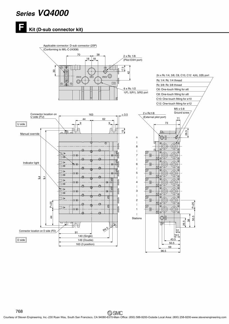
Kit (D-sub connector kit)F
Manifold Specifications
Series
VQ4000
Porting specifications
4(A), 2(B)
Port size
1(P), 5(R1), 3(R2)
Rc 1/2C 8, 10, 12Rc 1/4, 3/8
Rc 1/4
VV5Q
ManifoldOption
08
Stations
FC8 U
Cylinder portC6C8C10C120203B
CM
1 Plug-in unit
D-sub Connector CableAssembly Terminal No.Terminal no.
123456789
10111213141516171819202122232425
D-sub Connector CableAssemblyCablelength (L) Assembly part no. Note
1.5 m3 m5 m
AXT100-DS25-015AXT100-DS25-030AXT100-DS25-050
Item Characteristics
Conductor resistanceΩ/km, 20°CVoltage limitVAC, 1 min.
Insulation resistanceMΩkm, 20°C
65 orless
1000
5 or less
11
Series4 VQ4000
4
Connector entry directionDU
Cable (Length)0123
1644
L
8
14 25
1 13
47.04
55 2 x M2.6 x 0.45
D-Sub Connector Kit (25 pins)
How to Order Manifold
Simplification and labor savings for wiring work can be achieved by using a D-sub connector for the electrical connection.
Using connector for flat ribbon cable (25P) conforming to MIL standard permits the use of connectors put on the market and gives a wide interchangeability.
Connector entry can be selected on either the U side or the Dside according to the mounting orientation.
Maximum stations are 18.
4(A), 2(B)port
location
Applicablestations
Max. 18stations
AXT100-DS25-015030050
D-sub connector cable assemblies can be ordered by with manifolds. Refer to How to Order Manifold.
Multi-core vinyl cable0.3 mm2 x 25C
≅ø10
Socket side
Terminal no.
Cable 25 coresx 24AWG
∗ For other commercial connectors, use a 25 pins type with female connector conforming to MIL-C-24308.
∗ Cannot be used for transfer wiring.
Connector manufacturers’ example• Fujitsu, Ltd.• Japan Aviation Electronics Industry, Ltd.• J.S.T. Mfg. Co., Ltd.• Hirose Electric Co., Ltd.
ElectricCharacteristics
Note) The minimum bending radius for D-sub connector cables is 20 mm.
Cable assembly
Lead wire colorBlackBrownRed
OrangeYellowPinkBlue
PurpleGrayWhiteWhiteYellowOrangeYellowPinkBlue
PurpleGray
OrangeRed
BrownPinkGrayBlackWhite
NoneNoneNoneNoneNoneNoneNoneWhiteBlackBlackRed Red Red BlackBlackWhiteNoneNoneBlackWhiteWhiteRed Red WhiteNone
Dot marking
01 1 station
18 18 stations
•••
••• With One-touch fitting for ø6
With One-touch fitting for ø8With One-touch fitting for ø10With One-touch fitting for ø12
Rc 1/4Rc 3/8
Bottom ported Rc 1/4Mixed
Note) As an option, the maximum number of stations can be increased by special wiring specifications. For details, refer to page 767.
Without cableCable length 1.5 m Cable length 3 mCable length 5 m
D side entryU side entry
SymbolNil
CD (2) CU (2) K (3)
SBSD (2)
SU (2)
Option
NoneExhaust cleaner: For D side mountingExhaust cleaner: For U side mounting
Special wiring specifications (Except double wiring)
Direct exhaust with silencer box: Exhaust from both sidesDirect exhaust with silencer box: D side exhaustDirect exhaust with silencer box: U side exhaust
Note 1)
Note 2)
Note 3)
Note 4)
When two or more symbols are specified, indicate them alphabetically. Example) -CDKCombination of [C ] and [S ] is not possible.Specify the wiring specifications on the manifold specification sheet.Refer to pages 796 to 799 for with control unit.
UD
UD
CE-compliantNil —
CE-compliantQ
Side
Bottom
Note) Lengths other than the above are also available. Please contact SMC for details.
766
Series VQ4000
[Option]
VQ4000.qxd 10.11.25 9:47 AM Page 3
Courtesy of Steven Engineering, Inc.-230 Ryan Way, South San Francisco, CA 94080-6370-Main Office: (650) 588-9200-Outside Local Area: (800) 258-9200-www.stevenengineering.com

Coil voltage123456
100 VAC (50/60 Hz)200 VAC (50/60 Hz)110 VAC (50/60 Hz)220 VAC (50/60 Hz)
24 VDC12 VDC
Seal01
Metal sealRubber seal
FunctionNilY (1)
R (2)
Standard type (1 W)Low wattage type (0.5 W)
External pilot
Note 1) Applicable to DC specifications. Please select when you expect to energize the unit for extended periods of time. Refer to page 3 for details.
Note 2) Refer to page 795 for external pilot specification. Combination of external pilot and perfect interface is not possible.
Note 3) When two or more symbols are specified, indicate them alphabetically.
VQ 4
Type of actuation
Series
123456
NilB
Manual override
4 VQ4000
SOL.A1 1 (–) (+)
SOL.B14 14 (+) (–)
SOL.A2 2 (–) (+)
SOL.B15 15 (+) (–)
SOL.A3 3 (–) (+)
SOL.B16 16 (–) (+)
SOL.A4 4 (–) (+)
SOL.B17 17 (–) (+)
SOL.A5 5 (–) (+)
SOL.B18 18 (–) (+)
SOL.A6 6 (–) (+)
SOL.B19 19 (–) (+)
SOL.A7 7 (–) (+)
SOL.B20 20 (–) (+)
SOL.A8 8 (–) (+)
SOL.B21 21 (–) (+)
SOL.A9 9 (–) (+)
SOL.B22 22 (–) (+)
SOL.A10 10 (–) (+)
SOL.B23 23 (–) (+)
SOL.A11 11 (–) (+)
SOL.B24 24 (–) (+)
SOL.A12 12 (–) (+)
SOL.B25 25 (–) (+)
COM.13 13 (+) (–)
SOL.A
SOL.B
SOL.A
SOL.B
SOL.A
SOL.B
SOL.A
SOL.B
SOL.A
SOL.B
SOL.A
SOL.B
SOL.A
SOL.B
SOL.A
SOL.B
SOL.A
SOL.B
SOL.A
SOL.B
COM.
Terminal no. Terminal no. Polarity
Release valve
Pressure switch
Standard wiring Wiring with control unit
Special Wiring Specifications
0
NilE
YesWithout light, with surge voltage suppressor
Light/Surge voltage suppressor
25
24
23
14
15
16
17
18
19
20
21
22
12
11
10
1
2
3
4
5
6
7
8
9
13
25
24
23
14
15
16
17
18
19
20
21
22
12
11
10
1
2
3
4
5
6
7
8
9
13
COM
3m
1 0 5
How to Order Valves How to Order Manifold Assembly
D side 1 2 3 ····
········ S
tationsU side
Stations are counted starting from the first station on the D side.
Electrical wiring specifications
D-sub connector
Connector terminal no.
Double wiring (connected to SOL. A and SOL. B) is adopted for the internal wiring of each station, regardless of valve and option types. Mixed single and double wiring is available as an option. For details, refer to below.
Note) There is no polarity. It can also be used as a negative common.
1 station
2 stations
3 stations
4 stations
5 stations
6 stations
7 stations
8 stations
9 stations
10 stations
11 stations
12 stations
Note)
Lead wire color
Dot marking
AXT100-DS25- Wire colors
D-sub connector assembly015030050
Black None
Yellow Black
Brown None
Pink Black
Red None
Blue White
Orange None
Purple None
Yellow None
Gray None
Pink None
Orange Black
Blue None
Red White
Purple White
Brown White
Gray Black
Pink Red
White Black
Gray Red
White Red
Black White
Yellow Red
White None
Orange Red Positive
commonspecifications
Negative common
specifications
2. Wiring specificationsDouble wiring (connected to SOL. A and SOL. B) is used for the internal wiring of each station regardless of valve and option types.Mixed single and double wiring is available as an option.
1. How to orderIndicate option symbol “-K” in the manifold part number and be sure to specify station positions for single or double wiring on the manifold specification sheet.
Connections begin with the A side solenoid of the first station being connected to terminal no. 1, and continue in the order indicated by the arrows in the drawing without skipping any terminals.Maximum stations are 18.
D-sub connector
2 position single2 position double
3 position closed center3 position exhaust center3 position pressure center3 position double check
Non-locking push type (Tool required)Locking type (Tool required)
CE-compliantNil —
CE-compliantQ
Specify the part numbers for valves and optionstogether beneath the manifold base part number.
<Example>D-sub connector kit with cable (3 m)
VV5Q41-05C8FD2(-Q)···1 set∗VQ4100-5(-Q)········2 sets∗VQ4200-5(-Q)········2 sets∗VQ4300-5(-Q)··········1 set
—Manifold base part no.—Valve part no. (Stations 1 and 2)—Valve part no. (Stations 3 and 4)—Valve part no. (Station 5)
Prefix the asterisk to the part nos. of the solenoid valve, etc.
Enter in order starting from the first station on the D side. When entry of part numbers becomes complicated, indicate in the manifold specification sheet.
D side 1 2 3 ····
········S
tations
U side
767
Plug-in Unit Series VQ4000Base Mounted
[Option]
SJ
SY
SV
SYJ
SZ
VP4
S0700
VQ
VQ4
VQ5
VQC
VQZ
SQ
VFS
VFR
VQ7
VQ4000.qxd 10.11.25 9:47 AM Page 4
Courtesy of Steven Engineering, Inc.-230 Ryan Way, South San Francisco, CA 94080-6370-Main Office: (650) 588-9200-Outside Local Area: (800) 258-9200-www.stevenengineering.com
11
Kit (D-sub connector kit)F
P=
25
PE
R2R1
44
SMC
18
38
17.5
42
163
L1
L2
U side
D side
R4.5
SM
CS
MC
SM
CS
MC
SM
CS
MC
SM
C
3070
91
44 6215
26.5 38 50
.5P
=25
16.5
43.550.5
12
5996.5
1212
73
Connector location on U side (FU)
AA
BA
BA
BA
BA
BA
AA
AA
AA
A
BB
B
BB
X
2B
4A
2B
4A
2B
4A
2B
4A
2B
4A
2B
4A
2B
4A
2B
4A
X
P 1
2 x Rc 1/8(Pilot EXH port)
M5 x 0.8Ground screw
6 x Rc 1/21(P), 5(R1), 3(R2) port
2 x Rc1/8(External pilot port)
26.5
99
18
35
Applicable connector: D-sub connector (25P)(Conforming to MIL-C-24308)
Manual override
Indicator light
Connector location on D side (FD)
140 (Single)
149 (Double)
163 (3 position)
8
n···
······
······
······
······
7
6
5
4
3
2
1
Stations
2n x Rc 1/4, 3/8, C8, C10, C12 4(A), 2(B) port
Rc 1/4: Rc 1/4 thread
Rc 3/8: Rc 3/8 thread
C8: One-touch fitting for ø8
C6: One-touch fitting for ø6
C10: One-touch fitting for ø10
C12: One-touch fitting for ø12
≅ 3.5
768
Series VQ4000
P0759-P0850-E.qxd 08.9.1 2:58 PM Page 768
Courtesy of Steven Engineering, Inc.-230 Ryan Way, South San Francisco, CA 94080-6370-Main Office: (650) 588-9200-Outside Local Area: (800) 258-9200-www.stevenengineering.com
Bottom ported drawing12
43.5
50.5
P=
25
SM
CS
MC
SM
CS
MC
SM
CS
MC
SM
C
12
59
96.5
73
P=
25
37.5 10.2
91163
44
26.5 38 50
.5
L1
L2
4462
2 x Rc 1/8(External pilot port)
2n x Rc 1/4 4(A), 2(B) port
188
101
2113
126
3138
151
4163
176
5188
201
6213
226
7238
251
8263
276
9288
301
10313
326
11338
351
12363
376
L1
L2
L n
9
X12
X
B2
B2
B2
B2
B2
B2
B2
B2
AA
AA
AA
AA
BB
BB
BB
BB
Dimensions
9U side
D side
18513
526
17488
501
16463
476
15438
451
14413
426
13388
401
11
M5 x 0.8Ground screw
26.5
······
······
······
······
···
1
Stations
2
3
4
5
6
7
8
n
Connector location on U side (FU)
Connector location on D side (FD)
Formula L1 = 25n + 63, L2 = 25n + 76 n: Station (Maximum standard 18 stations)
769
Plug-in Unit Series VQ4000Base Mounted
SJ
SY
SV
SYJ
SZ
VP4
S0700
VQ
VQ4
VQ5
VQC
VQZ
SQ
VFS
VFR
VQ7
P0759-P0850-E.qxd 08.9.1 2:58 PM Page 769
Courtesy of Steven Engineering, Inc.-230 Ryan Way, South San Francisco, CA 94080-6370-Main Office: (650) 588-9200-Outside Local Area: (800) 258-9200-www.stevenengineering.com

Kit (Terminal block box kit)T
Manifold Specifications
Series
VQ4000
Porting specifications
4(A), 2(B)1(P), 5(R1), 3(R2)
Rc 1/2C8, 10, 12Rc 1/4, 3/8
Rc 1/4
VV5Q
ManifoldOption
08
Stations
OD
Box mounting position
TC8
Cylinder portC6C8C10C120203B
CM
1 Plug-in unit
1
Series4 VQ4000
4 0
Applicable terminal 1.25-3S, 1.25Y-3, 1.25Y-3N, 1.25Y-3.5Name plate: VVQ5000-N-TDrip proof plug assembly (for G 3/4): AXT100-B06A
Proper tightening torque (N·m)
0.7 to 1.2
Electrical entry
2 x G3/4
6mm
Terminal Block Connections
How to Order Manifold
Enclosure IP65 compliantThis type has a small terminal block inside a junction box.
The provision of a G 3/4 electrical entry allows connection of conduit fittings.
Maximum stations are 18.2 stations are used for terminal box mounting.
4(A), 2(B)port
location
Port size
Side
Bottom
Applicablestations
Max. 18 stations
Step 1. How to remove terminal block coverLoosen the 4 mounting screws (M4) and open the terminal block cover.
Step 2. The diagram on the right shows the terminal block wiring. All stations are provided with double wiring regardless of the valves which are mounted.Connect each wire to the power supply side, according to the markings provided inside the terminal block.Mounting screw
(M4)Terminal block cover
Gasket
Step 3. How to attach the terminal block coverSecurely tighten the screws with the torque shown in the table below, after confirming that the gasket is installed correctly.
M3 screw
03 3 stations
18 18 stations
•••
•••
Add 2 stations for terminal block box mounting.
Note)
With One-touch fitting for ø6With One-touch fitting for ø8
With One-touch fitting for ø10With One-touch fitting for ø12
Rc 1/4Rc 3/8
Bottom ported Rc 1/4Mixed
Note) As an option, the maximum number of stations can be increased by special wiring specifications. For details, refer to page 771.
U side mountingD side mounting
SymbolNil
CD (2)
CU (2)
K (3)
N (4)
SD (2)
SU (2)
W
OptionNone
Exhaust cleaner: For D side mountingExhaust cleaner: For U side mounting
Special wiring specifications (Except double wiring)Name plate
Direct exhaust with silencer box: D side exhaustDirect exhaust with silencer box: U side exhaust
IP65 enclosure
Note 1) When two or more symbols are specified, indicate them alphabetically. Example) -CDK
Note 2) Combination of [CD] and [SD] is not possible.Note 3) Specify the wiring specifications on the
manifold specification sheet.Note 4) Name plate is inlaid in the terminal block cover. Note 5) Refer to pages 796 to 799 for with control unit.
CE-compliantNil —
CE-compliantQ
770
Series VQ4000
IP65 compliant
[Option]
VQ4000.qxd 10.11.25 9:47 AM Page 5
Courtesy of Steven Engineering, Inc.-230 Ryan Way, South San Francisco, CA 94080-6370-Main Office: (650) 588-9200-Outside Local Area: (800) 258-9200-www.stevenengineering.com

VQ 4
Type of actuation
Series
123456
Seal01
Coil voltage
Manual override
Ligh/Surge voltage suppressor
4 VQ4000
SOL.A1A
SOL.B1B
SOL.A2A
SOL.B2B
SOL.A3A
SOL.B3B
SOL.A4A
SOL.B4B
SOL.A5A
SOL.B5B
SOL.A6A
SOL.B6B
SOL.A7A
SOL.B7B
SOL.A8A
SOL.B8B
SOL.A9A
SOL.B9B
SOL.A10A
SOL.B10B
Terminal no. Polarity
Special Wiring Specifications
0
123456
Function
COM
Enclosure
W
1A
1B
2A
2BSOL.A
3ASOL.B
3BSOL.A
4ASOL.B
4BSOL.A
5ASOL.B
5BSOL.A
6ASOL.B
6BSOL.A
7ASOL.B
7BSOL.A
8ASOL.B
8BSOL.A
9ASOL.B
9BSOL.A
10ASOL.B
10B
Terminal no.
COM
2 x G 3/4Electrical entry
Standard wiring Wiring with control unit
1 0 5
1ACOM
2A3A
4A5A
6A7A
8A9A
10A
1B2B
3B4B
5B6B
7B8B
9B10B
1B1A
2B2A
3B3A
4B4A
5B5A
6B6A
7B7A
8B8A
9B9A
10B10A
COM
1ACOM
2A3A
4A5A
6A7A
8A9A
10A
1B2B
3B4B
5B6B
7B8B
9B10B
1B
1A
2B
2A
3B
3A
4B
4A
5B
5A
6B
6A
7B
7A
8B
8A
9B
9A
10B
10ACOM
How to Order Valves How to Order Manifold Assembly
Stations are counted starting from the first station on the D side.
Electrical wiring specifications
Double wiring (connected to SOL. A and SOL. B) is adopted for the internal wiring of each station, regardless of valve and option types. Mixed single and double wiring is available as an option.
Note) There is no polarity. It can also be used as a negative common.
1 station
2 stations
3 stations
4 stations
5 stations
6 stations
7 stations
8 stations
9 stations
10 stations
Release valve
Pressure switch
(–) (+)
(+) (–)
(–) (+)
(+) (–)
(–) (+)
(–) (+)
(–) (+)
(–) (+)
(–) (+)
(–) (+)
(–) (+)
(–) (+)
(–) (+)
(–) (+)
(–) (+)
(–) (+)
(–) (+)
(–) (+)
(–) (+)
(–) (+)
(+) (–)
Positivecommon
Negativecommon
Double wiring (connected to SOL. A and SOL. B) is used for the internal wiring of each station regardless of valve and option types. The optional specification permits mixture of single and double wiring. However, the maximum number of stations is 16.
1. How to OrderIndicate option symbol “-K” in the manifold part number and be sure to specify station positions for single or double wiring on the manifold specification sheet.
2. Wiring specificationsConnections begin with the A side solenoid of the first station being connected to terminal no. 1, and continue in the order indicated by the arrows in the drawing without skipping any terminals.
2 position single2 position double
3 position closed center3 position exhaust center3 position pressure center3 position double check
Metal sealRubber seal
NilY (1)
R (2)
Standard type (1 W)Low wattage type (0.5 W)
External pilot
Nil Dust tight
Dust tight/Lowjetproof type (IP65)
NilB
Non-locking push type (Tool required)Locking type (Tool required)
NilE
YesWithout light, with surge voltage suppressor
100 VAC (50/60 Hz)200 VAC (50/60 Hz)110 VAC (50/60 Hz)220 VAC (50/60 Hz)
24 VDC12 VDC
Specify the part numbers for valves and options together beneath the manifold base part number.
<Example>Terminal block box kit
VV5Q41-07C8T0(-Q)···1 set∗VQ4100-5(-Q)·····2 sets∗VQ4200-5(-Q)·····2 sets∗VQ4300-5(-Q)·······1 set
—Manifold base part no.—Valve part no. (Stations 1 and 2)—Valve part no. (Stations 3 and 4)—Valve part no. (Station 5)
Prefix the asterisk to the part nos. of the solenoid valve, etc.
Enter in order starting from the first station on the D side. When entry of part numbers becomes complicated, indicate in the manifold specification sheet.
D side 1 2 3 ····
········S
tations U side
Note 1) Applicable to DC specifications.Please select when you expect to energize the unit for extended periods of time. Refer to page 3 for details.
Note 2) Refer to page 795 for external pilot specification. Combination of external pilot and perfect interface is not possible.
Note 3) When two or more symbols are specified, indicate them alphabetically.
CE-compliantNil —
CE-compliantQ
771
Plug-in Unit Series VQ4000Base Mounted
[Option]
SJ
SY
SV
SYJ
SZ
VP4
S0700
VQ
VQ4
VQ5
VQC
VQZ
SQ
VFS
VFR
VQ7
VQ4000.qxd 10.11.25 9:47 AM Page 6
Courtesy of Steven Engineering, Inc.-230 Ryan Way, South San Francisco, CA 94080-6370-Main Office: (650) 588-9200-Outside Local Area: (800) 258-9200-www.stevenengineering.com

Kit (Terminal block box kit)T
M5 x 0.8Ground screw
U side
D side
13012796.5
37.5
6244
91
73
96.559
12
70
30
R4.5
163
P=
2550
.538
26.5
50.543.5
16.5
4217
.5
38
18 18
9
44P
=25
2 x Rc 1/8(Pilot EXH port)
2 x Rc 1/8(External pilot port)
(Conduit port)2 x G 3/4
6 x Rc 1/21(P), 5(R1), 3(R2) port
NO.TERMin.ANAL
2B2A2
3B3A3
4B4A4
1B1A1
D SIDE
STA
U SIDE
SM
CS
MC
SM
CS
MC
SM
C
B
A
AB
B
A
AB
B
A
AB
A
A
A
A
4
B A
2
4
B A
2
SMC
4
B A
2
4
B A
2
4
B A
2
4
B A
2
4
B A
2
4
B
X12
X12
R1 R2 35 P 1
PE
A
2
11
26.515
L1L2
When D side mounting (TD)When U side mounting (TO)
Manual override
Indicator light
163 (3 position)149 (Double)140 (Single)
······
······
······
······
1
Stations
2
3
4
5
6
7
8
n
3.5
2n x Rc 1/4, 3/8, C8, C10, C12 4(A), 2(B) port
Rc 1/4: Rc 1/4 thread
Rc 3/8: Rc 3/8 thread
C8: One-touch fitting for ø8
C6: One-touch fitting for ø6
C10: One-touch fitting for ø10
C12: One-touch fitting for ø12
Note) Shown VV5Q41-08C12TO-W
772
Series VQ4000
P0759-P0850-E.qxd 08.9.1 2:58 PM Page 772
Courtesy of Steven Engineering, Inc.-230 Ryan Way, South San Francisco, CA 94080-6370-Main Office: (650) 588-9200-Outside Local Area: (800) 258-9200-www.stevenengineering.com

Bottom ported drawing
U side
D side
3138
151
4163
176
5188
201
6213
226
7238
251
8263
276
9288
301
10313
326
L1
L2
L n
Dimensions11338
351
12363
376
18513
526
17488
501
16463
476
15438
451
14413
426
13388
401
37.5
130127
96.5 62 449 9
16391
10.237.5
L2
L1
P=
2544
73
96.559
12
P=
2550
.538
26.5
50.543.5
(Conduit port)
2 x G 3/4
4(A), 2(B) port
2n x Rc 1/4
(External pilot port)2 x Rc 1/8
SM
CS
MC
SM
CS
MC
SM
C
4
B A
2
4
B A
2B
2B
2B
2B
2B
2B
X12
X12
2
AA
AA
AAB
BB
BB
B
M5 x 0.8Ground screw
11
26.5
1
Stations
······
······
······
······
···
2
3
4
5
6
7
8
n
Formula L1 = 25n + 63, L2 = 25n + 76 n: Station (Maximum standard 18 stations) ∗ Including 2 stations for terminal box.
773
Plug-in Unit Series VQ4000Base Mounted
SJ
SY
SV
SYJ
SZ
VP4
S0700
VQ
VQ4
VQ5
VQC
VQZ
SQ
VFS
VFR
VQ7
P0759-P0850-E.qxd 08.9.1 2:58 PM Page 773
Courtesy of Steven Engineering, Inc.-230 Ryan Way, South San Francisco, CA 94080-6370-Main Office: (650) 588-9200-Outside Local Area: (800) 258-9200-www.stevenengineering.com

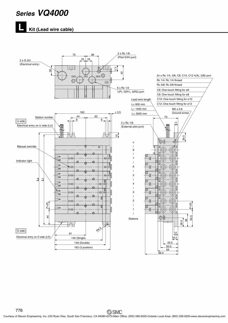
Kit (Lead wire cable)L
Manifold Specifications
Series
VQ4000
4(A), 2(B)1(P), 5(R1), 3(R2)
Rc 1/2C 8, 10, 12Rc 1/4, 3/8
Rc 1/4
Wiring Specifications
VV5Q
Manifold
08
Stations
LC8
1 Plug-in unit
1
Series4 VQ4000
4
SOL.A
COM
SOL.B
Lead wire color
SOL.A
COM
SOL.B
Lead wire color
Single solenoid Double solenoid
Lead Wire Assembly with Connector
U
1
How to Order Manifold
IP65 compliant
Enclosure IP65 compliantDirect electrical entry. Models with two or more stations are
available.Electrical entry can be selected on either the U side or the D
side according to the mounting orientation.Maximum stations are 16.
Porting specifications4(A), 2(B)
portlocation
Port size
Side
Bottom
Applicablestations
Max. 16 stations
Three lead wires are attached to each station regardless of the type of valve which is mounted.The red wire is for COM connection.
(+)
(–)
(+)
Black
Red
White
(–)
(+)
(–)
Positivecommon
Negativecommon
(+)
(–)
(+)
Black
Red
White
Positivecommon
Negativecommon
(–)
(+)
(–)
Lead wire length
0.6 m
1.5 m
3 m
Part no.
VVQ5000-44A-8-
VVQ5000-44A-15-
VVQ5000-44A-30-: Number of stations 1 to 16.
Station number
Cable: 3 core 24 x AWG
Black: A side solenoid (–)
Red: COM (+)
White: B side solenoid (–)(Not used for single solenoid)
For different lead wire lengths, order a lead wire assembly with connector shown in the table on the right.Note 1) There is no polarity. It can also be used as a negative common.Note 2) Connect the release valve and the pressure switch to SOL. A side on the manifold with control unit.
01 1 station
16 16 stations
•••
•••
Cylinder portWith One-touch fitting for ø6 With One-touch fitting for ø8With One-touch fitting for ø10With One-touch fitting for ø12
Rc 1/4Rc 3/8
Bottom ported Rc 1/4Mixed
C6C8C10C120203B
CM
OptionSymbol
NilCDCUSBSDSUW
OptionNone
Exhaust cleaner: For D side mountingExhaust cleaner: For U side mounting
Direct exhaust with silencer box: Exhaust from both sidesDirect exhaust with silencer box: D side exhaustDirect exhaust with silencer box: U side exhaust
IP65 enclosureNote) When two or more symbols are specified, indicate them alphabetically.
Example) -CDW
Cable (Length)012
Cable length 0.6 mCable length 1.5 m Cable length 3 m
Connector locationsDU
D side entryU side entry
CE-compliantNil —
CE-compliantQ
774
Series VQ4000
[Option]
VQ4000.qxd 10.11.25 9:47 AM Page 7
Courtesy of Steven Engineering, Inc.-230 Ryan Way, South San Francisco, CA 94080-6370-Main Office: (650) 588-9200-Outside Local Area: (800) 258-9200-www.stevenengineering.com

VQ 4
Type of actuation
Series
123456
Seal01
Coil voltage
Manual override
Light /Surge voltage suppressor
4 VQ4000
0
123456
Function
Enclosure
1 0 5
How to Order Valves How to Order Manifold Assembly
D side1
2 3 ····
··········
··········
Stations
U side
Cable length
The drawing shows the electrical entry on the D side.Cable length is measured from the solenoid valve body.
2 position single2 position double
3 position closed center3 position exhaust center3 position pressure center3 position double check
Metal sealRubber seal
NilY (1)
R (2)
Standard type (1 W)Low wattage type (0.5 W)External pilot
Applicable to DC specification. Please select when you expect to energize the unit for extended periods of time. Refer to page 3 for details.Refer to page 795 for external pilot specification. Combination of external pilot and perfect interface is not possible.When two or more symbols are specified, indicate them alphabetically.
Note 1)
Note 2)
Note 3)
Nil Dust tight
WDust tight/Low jetproof type
(IP65)
NilB
Non-locking push type (Tool required)Locking type (Tool required)
NilE
YesWithout light, with surge voltage suppressor
100 VAC (50/60 Hz)200 VAC (50/60 Hz)110 VAC (50/60 Hz)220 VAC (50/60 Hz)
24 VDC12 VDC
CE-compliantNil —
CE-compliantQ
Specify the part numbers for valves and options together beneath the manifold base part number.
<Example>Lead wire kit with cable (3 m)
VV5Q41-05C8LD2(-Q)··· 1 set∗VQ4100-5(-Q)·······2 sets∗VQ4200-5(-Q)·······2 sets∗VQ4300-5(-Q) ·····1 set
—Manifold base part no.—Valve part no. (Stations 1 and 2)—Valve part no. (Stations 3 and 4)—Valve part no. (Station 5)
Prefix the asterisk to the part nos.of the solenoid valve, etc.
Enter in order starting from the first station on the D side. When entry of part numbers becomes complicated, indicate in the manifold specification sheet.
1 2 3 ·········
···Stations
D side
U side
775
Plug-in Unit Series VQ4000Base Mounted
[Option]
SJ
SY
SV
SYJ
SZ
VP4
S0700
VQ
VQ4
VQ5
VQC
VQZ
SQ
VFS
VFR
VQ7
VQ4000.qxd 10.11.25 9:47 AM Page 8
Courtesy of Steven Engineering, Inc.-230 Ryan Way, South San Francisco, CA 94080-6370-Main Office: (650) 588-9200-Outside Local Area: (800) 258-9200-www.stevenengineering.com
Kit (Lead wire cable)L
P=
25
PE
R2R1
44
SMC
18
38
17.5
42
163
L1
L2
U side
D side R4.5
30
70
SM
CS
MC
SM
CS
MC
SM
CS
MC
SM
C
91
44 6215
38
26.5
50.5
P=
25
16.5
43.550.5
12
5996.5
73
BA
BA
BA
BA
BA
AA
AA
AA
AA
A
BB
B
BB
2 x G 3/4(Electrical entry)
2 x Rc 1/8(Pilot EXH port)
6 x Rc 1/21(P), 5(R1), 3(R2) port
2 x Rc 1/8(External pilot port)
2B
12X
4A
2B
4A
2B
4A
2B
4A
2B
4A
2B
4A
2B
4A
2B
4A
12X
5 P 1 3
9
18
9
M5 x 0.8Ground screw
11
26.5
≅ 3.5
Station number
Electrical entry on U side (LU)
Manual override
Indicator light
Electrical entry on D side (LD) 140 (Single)
149 (Double)
163 (3 position)
1
Stations
······
······
······
······
···
2
3
4
5
6
7
8
n
Lead wire length
L0: 600 mm
L1: 1500 mm
L2: 3000 mm
2n x Rc 1/4, 3/8, C8, C10, C12 4(A), 2(B) port
Rc 1/4: Rc 1/4 thread
Rc 3/8: Rc 3/8 thread
C8: One-touch fitting for ø8
C6: One-touch fitting for ø6
C10: One-touch fitting for ø10
C12: One-touch fitting for ø12
776
Series VQ4000
P0759-P0850-E.qxd 08.9.1 2:58 PM Page 776
Courtesy of Steven Engineering, Inc.-230 Ryan Way, South San Francisco, CA 94080-6370-Main Office: (650) 588-9200-Outside Local Area: (800) 258-9200-www.stevenengineering.com

Bottom ported drawing
12
43.550.5
U side
D side
SM
CS
MC
SM
CS
MC
SM
CS
MC
SM
C
12
59
96.5
73
91
37.5 10.2
163
44P
=25
26.5
26.5
38 50.5
P=
25
L1
L2
4462
188
101
2113
126
3138
151
4163
176
5188
201
6213
226
7238
251
8263
276
L1
L2
L n
2 x Rc 1/8(External pilot port)
2n x Rc 1/44(A), 2(B) port
9288
301
10313
326
11338
351
12363
376
13388
401
14413
426
15438
451
16463
476
9
X
2B
2B
2B
2B
2B
2B
2B
2B
12X
BB
BB
BB
BB
AA
AA
AA
AA
Dimensions
911
M5 x 0.8Ground screw
Lead wire length
L0: 600 mm
L1: 1500 mm
L2: 3000 mm
1
Stations
······
······
······
······
···
2
3
4
5
6
7
8
n
Station number
Electrical entry on U side (LU)
Electrical entry on D side (LD)
Formula L1 = 25n + 63, L2 = 25n + 76 n: Station (Maximum 16 stations)
777
Plug-in Unit Series VQ4000Base Mounted
SJ
SY
SV
SYJ
SZ
VP4
S0700
VQ
VQ4
VQ5
VQC
VQZ
SQ
VFS
VFR
VQ7
P0759-P0850-E.qxd 08.9.1 2:58 PM Page 777
Courtesy of Steven Engineering, Inc.-230 Ryan Way, South San Francisco, CA 94080-6370-Main Office: (650) 588-9200-Outside Local Area: (800) 258-9200-www.stevenengineering.com

Kit (Serial transmission unit): EX123/124 Integrated Type (for Output) Serial Transmission SystemS
VV5Q
Manifold
08
Stations
SC8
Cylinder portsC6C8C10C120203B
CM
SI unit mounting position
1 Plug-in unit
1
Series4 VQ4000
4 V
F1
H
J1
J2
Q
R1
R2
V
Protocol typeSymbol
NKE Corp.: Uni-wire System
NKE Corp.: Uni-wire H System
SUNX Corp.: S-LINK System (16 output points)
SUNX Corp.: S-LINK System (8 output points)
DeviceNet
OMRON Corp.: CompoBus/S System (16 output points)
OMRON Corp.: CompoBus/S System (8 output points)
CC-Link
SI unit part no. Page
P.1653
Refer to pages 1653 to 1655 for EX123/124 integrated type (for output) serial transmission system.
D side: EX123D-SUH1U side: EX123U-SUH1
D side: EX123D-SSL1U side: EX123U-SSL1
D side: EX123D-SSL2U side: EX123U-SSL2
D side: EX124D-SDN1U side: EX124U-SDN1
D side: EX124D-SCS1U side: EX124U-SCS1
D side: EX124D-SCS2U side: EX124U-SCS2
D side: EX124D-SMJ1U side: EX124U-SMJ1
D side: EX123D-SUW1U side: EX123U-SUW1
How to Order Manifold
The serial transmission system reduces wiring work, while minimizing wiring and saving space.
Manifold Specifications
Series
VQ4000
Porting specifications
1(P) ,5(R1), 3(R2) 4(A), 2(B)
Rc 1/2C8, 10, 12Rc 1/4, 3/8
Rc 1/4
Double wiring (connected to SOL. A and SOL. B) is adopted for the internal wiring of each station, regardless of valve and option types.
Specifications
0.1A
Drip proof plug assembly (for G 1/2): AXT100-B04A
IP65 compliant
4(A), 2(B) portport location
Port size
Side
Bottom
Applicable stations
Max. 18 stations
Item
Current consumption(Internal unit)
External power supply 24 VDC +10%, –5%
03 3 stations
18 18 stations
•••
•••
Stations are counted starting from the first station on the D side.
With One-touch fitting for ø6 With One-touch fitting for ø8With One-touch fitting for ø10With One-touch fitting for ø12
Rc 1/4Rc 3/8
Bottom ported Rc 1/4Mixed
NilD
U side mountingD side mounting
Note) Add 2 stations for SI unit mounting. Maximum stations are 18. 2 stations are used for SI unit mounting.
SI Unit Part No.
OptionSymbol
NilCD (2)
CU (2)
K (3)
SD (2)
SU (2)
W (2)
OptionNone
Exhaust cleaner: D side mountingExhaust cleaner for Rc 1: U side exhaust
Special wiring specifications (Except double wiring)Direct exhaust with silencer box: D side exhaustDirect exhaust with silencer box: U side exhaust
IP65 enclosure
SI unit0
F1HJ1J2QR1R2V
Without SI unitNKE Corp.: Uni-wire System
NKE Corp.: Uni-wire H SystemSUNX Corp.: S-LINK System (16 output points)SUNX Corp.: S-LINK System (8 output points)
DeviceNetOMRON Corp.: CompoBus/S System (16 output points)OMRON Corp.: CompoBus/S System (8 output points)
CC-Link
CE-compliant—
CE-compliantQNil
Note 1) When two or more symbols are specified, indicate them alphabetically. Example) -CDK
Note 2) Combination of [CD] and [SD] is not possible.Note 3) Specify the wiring specifications in the manifold specification sheet.Note 4) Refer to pages 796 to 799 for with control unit.consumption of AC type.Note 5) The release valve and the pressure switch on the manifold with control unit
are connected to another power supply.Cable length is 0.6 m for L kit.
CE-compliant
1 2 3 ·········
···Stations
G 1/2
D side
U side
778
Series VQ4000
[Option]
VQ4000.qxd 10.11.25 9:47 AM Page 9
Courtesy of Steven Engineering, Inc.-230 Ryan Way, South San Francisco, CA 94080-6370-Main Office: (650) 588-9200-Outside Local Area: (800) 258-9200-www.stevenengineering.com

VQ 4
Type of actuation
Series
123456
Seal01
Coil voltage
Manual override
4 VQ4000
0
5 24 VDC
Function
Enclosure
51 0
How to Order Valves How to Order Manifold Assembly [Order example]
2 position single2 position double
3 position closed center3 position exhaust center3 position pressure center3 position double check
Metal sealRubber seal
Nil Dusttight
W Dusttight/Low jetproof type(IP65)
NilB
Non-locking push type (Tool required)Locking type (Tool required)
NilY (1)
R (2)
Standard type (1 W)Low wattage type (0.5 W)
External pilot
Specify the part numbers for valves and options together beneath the manifold base part number.
<Example>VV5Q41-07C8SV(-Q) ···1 set∗VQ4100-5(-Q)······2 sets∗VQ4200-5(-Q)······2 sets∗VQ4300-5(-Q)········1 set
—Manifold base part no.—Valve part no. (Stations 1 and 2)—Valve part no. (Stations 3 and 4)—Valve part no. (Station 5)
Prefix the asterisk to the part nos. of the solenoid valve, etc.
Enter in order starting from the first station on the D side.When entry of part numbers becomes complicated, indicate in the manifold specification sheet.
Note 1) Applicable to DC specifications. Please select when you expect to energize the unit for extended periods of time. Refer to page 3 for details.
Note 2) For external pilot specifications, refer to page 795. Combination of the external pilot and perfect interface is not possible.
Note 3) When two or more symbols are specified, indicate them alphabetically.
CE-compliantNil —
CE-compliantQ
[Option]
1 2 3 ·········
···Stations
D side
U side
779
Plug-in Unit Series VQ4000Base Mounted
SJ
SY
SV
SYJ
SZ
VP4
S0700
VQ
VQ4
VQ5
VQC
VQZ
SQ
VFS
VFR
VQ7
VQ4000.qxd 10.11.25 9:47 AM Page 10
Courtesy of Steven Engineering, Inc.-230 Ryan Way, South San Francisco, CA 94080-6370-Main Office: (650) 588-9200-Outside Local Area: (800) 258-9200-www.stevenengineering.com

Kit (Serial transmission unit): EX123/124 Integrated Type (for Output) Serial Transmission SystemS
U side
D side
13095
35.5
91
73
96.559
12R4.5
L2
L1
P=
2550
.538
26.5
50.543.5
16.5
44P
=25
TM
1(P), 5(R1), 3(R2) port
6 x Rc 1/2
(Pilot EXH port)
2 x Rc 1/8
MODEL SQ (SI No.EX124-SDN1)
0
1
SETTINGS
MOD/NET PWR
(External pilot port)
2 x Rc 1/8
(Conduit port)
4(2) x G 1/2
SM
CS
MC
SM
CS
MC
SM
CBA
AB
BA
AB
BA
AB
A
A
A
A4
B A
2
4
B A
2
SMC
4
B A
2
4
B A
2
4
B A
2
4
B A
2
4
B A
2
4
B
X12
X12
R1 R2 35 P 1
PE
A
2
70
30
42
17.5
38
18 18
163
44
9 9
15
62
3138
151
4163
176
5188
201
6213
226
7238
251
8263
276
L1
L2
L n
Dimensions9
288
301
10313
326
18513
526
17488
501
16463
476
15438
451
14413
426
13388
401
12363
376
11338
351
M5 x 0.8Ground screw
11
26.5
SI Unit
When D side mounting (SD)
When U side mounting (S)
Manual override
Indicator light
163 (3 position)149 (Double)
140 (Single)
······
······
······
······
···
Stations
1
2
3
4
5
6
7
8
n
C12: One-touch fitting for ø12
C10: One-touch fitting for ø10
C8: One-touch fitting for ø8
C6: One-touch fitting for ø6Rc 3/8: Rc 3/8 thread
Rc 1/4: Rc 1/4 thread
2n x Rc 1/4, 3/8, C8, C10, C12 4(A), 2(B) port
Note)
Note) In the case of EX124 for SI unit, conduit port (G 1/2)will be 4 locations. In the case of EX123D (U), conduit port will be 2 locations.
Formula L1 = 25n + 63, L2 = 25n + 76 n: Station (Maximum standard 18 stations) ∗ Including 2 stations for mounting SI unit box.
Note) Shown VV5Q41-08C12SQ-W
≅ 3.5
780
Series VQ4000
P0759-P0850-E.qxd 08.9.1 2:58 PM Page 780
Courtesy of Steven Engineering, Inc.-230 Ryan Way, South San Francisco, CA 94080-6370-Main Office: (650) 588-9200-Outside Local Area: (800) 258-9200-www.stevenengineering.com

U side
D side
3138
151
4163
176
5188
201
6213
226
7238
251
8263
276
L1
L2
L nDimensions
9288
301
10313
326
18513
526
17488
501
16463
476
15438
451
14413
426
13388
401
12363
376
11338
351
13095
35.5
62 449 9
16391
10.237.5
L2
L1
P=
2544
73
96.559
12
P=
2550
.538
26.5
50.543.5
(External pilot port)2 x Rc 1/8
(Conduit port) Note)4(2) G 1/2
4(A), 2(B) port2n x Rc 1/4
SM
CS
MC
SM
CS
MC
SM
C
4
B A
2
4
B A
2B
2B
2B
2B
2B
2B
X12
X12
2
11
26.5
M5 x 0.8Ground screw
AA
AA
AA
BB
BB
BB
······
······
······
······
···
Stations
1
2
3
4
5
6
7
8
n
Formula L1 = 25n + 63, L2 = 25n + 76 n: Station (Maximum standard 18 stations) ∗ Including 2 stations for mounting SI unit box.
781
Plug-in Unit Series VQ4000Base Mounted
SJ
SY
SV
SYJ
SZ
VP4
S0700
VQ
VQ4
VQ5
VQC
VQZ
SQ
VFS
VFR
VQ7
P0759-P0850-E.qxd 08.9.1 2:58 PM Page 781
Courtesy of Steven Engineering, Inc.-230 Ryan Way, South San Francisco, CA 94080-6370-Main Office: (650) 588-9200-Outside Local Area: (800) 258-9200-www.stevenengineering.com

Kit (Serial transmission kit): EX240 Integrated Type (for I/O) Serial Transmission SystemS
Option
DI unit specifications
08
Stations
DU
Mounting SI unit
SI unit
Si unit COM
SymbolNilK
OptionNone
Special wiring specification (Except double wiring)
SC8
Cylinder portsSymbolC6C8C10C120203B
CM
DI unitNil01234
Nil N
With no SI/Input unitDeviceNet
PROFIBUS DP+COM.–COM.
OWQWNW
Without SI unitDeviceNet
PROFIBUS DP
Nil
N
PNP sensor input (+COM) orno SI unit or DI unit
NPN sensor input (–COM)
QW WD 1VV5Q
Manifold1 Plug-in unit
1
Series4 VQ4000
4
How to Order Manifold
QWNW
Protocol typeSymbolDeviceNet
PROFIBUS DP
SI unit part no. Page
P.1661
Refer to pages 1661 to 1663 for EX240 integrated type (for I/O) serial transmission system.
EX240-SDN2EX240-SPR1
IP65 compliant
01 1 station
16 16 stations
•••
•••
Port sizeWith One-touch fitting for ø6With One-touch fitting for ø8With One-touch fitting for ø10With One-touch fitting for ø12
Rc 1/4Rc 3/8
Bottom ported Rc 1/4Mixed
D side mountingU side mounting
Without SI unitWithout DI unitWith 1 DI unitWith 2 DI unitsWith 3 DI unitsWith 4 DI units
Note) Only +COM is available for Si unit compatible with DeviceNet, while only -COM for the unit compatible with PROFIBUS DP.
SI Unit Part No.
Enclosure IP65 (Dusttight/Low jetproof type)
782
Series VQ4000
[Option]
CE-compliantNil —
CE-compliantQ
VQ4000.qxd 10.11.25 9:47 AM Page 11
Courtesy of Steven Engineering, Inc.-230 Ryan Way, South San Francisco, CA 94080-6370-Main Office: (650) 588-9200-Outside Local Area: (800) 258-9200-www.stevenengineering.com

VQ 4
Type of actuation
Series
123456
Seal01 Coil voltage
Manual override
Enclosure
4 VQ4000
0
5
Function
51 0
How to Order Valves How to Order Manifold Assembly [Order example]
2 position single2 position double
3 position closed center3 position exhaust center3 position pressure center3 position double check
Metal sealRubber seal
Nil
W
CE-compliantNil —
CE-compliantQ
Dusttight
Dusttight /Low jetproof type
(IP65)
NilB
Non-locking push type (Tool required)Locking type (Tool required)
24 VDC
NilY (1)
R (2)
Standard type (1 W)Low wattage type (0.5 W)
External pilot
Specify the part numbers for valves and options together beneath the manifold base part number.
<Example>VV5Q41-05C8SDQW1-W(-Q)····1 set∗VQ4100-5W(-Q)········2 sets∗VQ4200-5W(-Q)·····2 sets∗VQ4300-5W(-Q)····1 set
—Manifold base part no.
—Valve part no. (Stations 1 and 2)—Valve part no. (Stations 3 and 4)—Valve part no. (Station 5)
Prefix the asterisk to the part nos. of the solenoid valve, etc.
Enter in order starting from the first station on the D side. When entry of part numbers becomes complicated, indicate in the manifold specification sheet.
Note 1) Applicable to DC specifications. Please select when you expect to energize the unit for extended periods of time. Refer to page 3 for details.
Note 2) For external pilot specifications, refer to page 795. Combination of the external pilot and perfect interface is not possible.
Note 3) When two or more symbols are specified, indicate them alphabetically.
783
Plug-in Unit Series VQ4000Base Mounted
[Option]
SJ
SY
SV
SYJ
SZ
VP4
S0700
VQ
VQ4
VQ5
VQC
VQZ
SQ
VFS
VFR
VQ7
VQ4000.qxd 10.11.25 9:47 AM Page 12
Courtesy of Steven Engineering, Inc.-230 Ryan Way, South San Francisco, CA 94080-6370-Main Office: (650) 588-9200-Outside Local Area: (800) 258-9200-www.stevenengineering.com

12
1.6
R4.5
9 9
23 75.58 61.5
96.543.5
16.5
99 32143 10
72
163106 10
4217
.5
381818
54
14.5
8(1
28.5
)P
=25
446.
5L
1
Rc 1/8
Rc 1/8
3 x Rc 1/2
PE
1P5 3R2R1
SMC
12X
2
AB
4
2
AB
4
2
AB
4
2
AB
4
2
AB
4
2
AB
4
2
AB
4
2
AB
4
SM
C
A
A
A
A
BA
A
B
BA
A
B
BA
A
B
BA
A
B
BA
A
B
SM
CS
MC
SM
CS
MC
SM
CS
MC
1
2
3
4
5
6
7
8
n
U side
D side
L2
(In
the
case
of D
I uni
t, 1p
c: 8
num
ber
of in
puts
)
Manual override
Indicator light
Mounting holefor 2 x M5
DI unit
SI unit
Stations
······
······
······
······
···
(External pilot port)
1(P), 5(R1), 3(R2) port
Min
. 0 to
max
4 un
it(0
to 2
16 m
m)
(Pilot EXH port)
C12: One-touch fitting for ø12C10: One-touch fitting for ø10
C6: One-touch fitting for ø6C8: One-touch fitting for ø8
Rc 3/8: Rc 3/8 threadRc 1/4: Rc 1/4 thread
2n x Rc 1/4, 3/8, C8, C10, C12 4(A), 2(B) port
Kit (Serial transmission unit): EX240 Integrated Type (for I/O) Serial Transmission SystemS
2113
248
3138
273
4163
298
5188
323
6213
348
7238
373
8263
398
L1
L2
L n
Dimensions16463
598
15438
573
14413
548
13388
523
12363
498
11338
473
10313
448
9288
423
Formula L1 = 25n + 63, L2 = 25n + 198n: Stations ∗ In the case of DI unit, 1 pc., 54 mm is added per 1 pc.
784
Series VQ4000
P0759-P0850-E.qxd 08.9.1 2:58 PM Page 784
Courtesy of Steven Engineering, Inc.-230 Ryan Way, South San Francisco, CA 94080-6370-Main Office: (650) 588-9200-Outside Local Area: (800) 258-9200-www.stevenengineering.com
U side
D side
12X
2
AB
4
2
AB
4
2
AB
4
2
AB
4
2
AB
4
2
AB
4
2
AB
4
2
AB
4
SM
C
A
A
A
A
BA
A
B
BA
A
B
BA
A
B
BA
A
B
BA
A
B
SM
CS
MC
SM
CS
MC
SM
CS
MC
PE
1P5 3R2R1
SMC
R4.5
1.6
23 75.58 61.5
Rc 1/8
3 x Rc 1/2
12
96.543.5
16.5
Rc 1/8
72
4217
.5
381818
99 32143 10
9 9
163106 10
54
14.5 8
(182
.5)
P=2
544
6.5
L1
54
1
2
3
4
5
6
7
8
n
Min
. 0 to
max
4 un
it(0
to 2
16 m
m)
L2
(In
the
case
of 2
pcs
. DI u
nit:
16 n
umbe
r of
inpu
ts)
Manual override
Indicator light
Mounting holefor 2 x M5
DI unit
SI unit
Stations
······
······
······
······
···
(External pilot port)
1(P), 5(R1), 3(R2) port
(Pilot EXH port)
C12: One-touch fitting for ø12
C10: One-touch fitting for ø10
C8: One-touch fitting for ø8
Rc 3/8: Rc 3/8 thread
Rc 1/4: Rc 1/4 thread
2n x Rc 1/4, 3/8, C8, C10, C12 4(A), 2(B)
2113
302
3138
327
4163
352
5188
377
6213
402
7238
427
8263
452
L1
L2
L nDimensions
16463
652
15438
627
14413
602
13388
577
12363
552
11338
527
10313
502
9288
477
Formula L1 = 25n + 63, L2 = 25n + 252n: Stations
∗ In the case of 2 pcs. DI unit, 105 mm will be added per 2 pcs.
785
Plug-in Unit Series VQ4000Base Mounted
SJ
SY
SV
SYJ
SZ
VP4
S0700
VQ
VQ4
VQ5
VQC
VQZ
SQ
VFS
VFR
VQ7
P0759-P0850-E.qxd 08.9.1 2:58 PM Page 785
Courtesy of Steven Engineering, Inc.-230 Ryan Way, South San Francisco, CA 94080-6370-Main Office: (650) 588-9200-Outside Local Area: (800) 258-9200-www.stevenengineering.com

Electrical entry
GLead wire
length0.6 m
HLead wire
length1.5 m
VQ 4
Type of actuation
Series
123456
Seal01
Manual override
4 VQ4000
5
Function
VV5Q
Manifold Option
08
Stations
C8
Cylinder portC6C8C10C120203B
CM
5 Plug lead unit
5
Series4 VQ4000
4 W
Control unit
Kit type
C
C kit (Connector)
Connector kitC
Enclosure
Light/Surge voltage suppressor
Coil voltage123
456
0 5 G1
How to Order Manifold
How to Order Valves How to Order Manifold Assembly
Base MountedPlug Lead Unit: C Kit (Connector kit)
Series VQ4000
01 1 station
16 16 stations
•••
•••
With One-touch fitting for ø6 With One-touch fitting for ø8With One-touch fitting for ø10With One-touch fitting for ø12
Rc 1/4Rc 3/8
Bottom ported Rc 1/4Mixed
Refer to pages 796 to 799.
Max. 16 stations
SymbolNil
CD (2)
CU (2)
SBSD (2)
SU (2)
W
OptionNone
Exhaust cleaner: For D side mountingExhaust cleaner: For U side mounting
Direct exhaust with silencer box: Exhaust from both sidesDirect exhaust with silencer box: D side exhaustDirect exhaust with silencer box: U side exhaust
IP65 enclosure
UD
UD
Note 1) When two or more symbols are specified, indicate them alphabetically.Example) -CDW
Note 2) Combination of [C ] and [S ] is not available.
Refer to page 804 (Grommet type) forwiring specifications.
CE-compliantNil —
CE-compliantQ
2 position single2 position double
3 position closed center3 position exhaust center3 position pressure center3 position double check
Metal sealRubber seal
NilY (1)
R (2)
Standard type (1 W)Low wattage type (0.5 W)
External pilot
100 VAC (50/60 Hz)200 VAC (50/60 Hz)110 VAC (50/60 Hz)
220 VAC (50/60 Hz)24 VDC12 VDC
Nil Dusttight
W Dusttight/Lowjetproof type (IP65)
Nil: Non-locking push type (Tool required)
B: Locking type(Tool required)
NilE
YesWithout light, with surge voltage suppressor
Gro
mm
et
Specify the part numbers for valves and options together beneath the manifold base part number.
<Example>Connector kit
VV5Q45-05C12C(-Q)···1 set∗VQ4150-5G(-Q)······2 sets∗VQ4250-5G(-Q)······2 sets∗VQ4350-5G(-Q)···1 set
—Manifold base part no.—Valve part no. (Stations 1 and 2)—Valve part no. (Stations 3 and 4)—Valve part no. (Station 5)
Prefix the asterisk to the part nos. of the solenoid valve, etc.
Enter in order starting from the first station on the D side. When entry of part numbers becomes complicated, indicate in the manifold specification sheet.
D side
U side
1 2 3 ·········
···Stations
Simple specials are available with SMC Simple Special System. For details about applicable models, refer to front matter 53.
Note 1) Applicable to DC specifications. Please select when you expect to energize the unit for extended periods of time. Refer to page 3 for details.
Note 2) For external pilot specifications, refer to page 795. Combination of the external pilot and perfect interface is not possible.
Note 3) When two or more symbols are specified, indicate them alphabetically.
[Option]
CE-compliantNil —
CE-compliantQ
786
VQ4000.qxd 10.11.25 9:47 AM Page 13
Courtesy of Steven Engineering, Inc.-230 Ryan Way, South San Francisco, CA 94080-6370-Main Office: (650) 588-9200-Outside Local Area: (800) 258-9200-www.stevenengineering.com

Manifold Specifications
VQ4000
Series Base model Type of connection
Rc 1/4
Flow Characteristics at the Number of Manifold Stations (Operated individually) Model
5.9
0.23
1.5
6.2
0.19
1.5
6.8
0.31
1.8
7.0
0.38
1.9
5.9
0.23
1.5
6.2
0.19
1.5
6.8
0.31
1.8
7.0
0.38
1.9
5.9
0.23
1.5
6.2
0.19
1.5
6.8
0.31
1.8
7.0
0.38
1.9
5.9
0.23
1.5
6.2
0.19
1.5
6.8
0.31
1.8
7.0
0.38
1.9
Passage/Stations
Manifold Option
n: Stations
Porting specifications
4(A), (B) port
location
Port size Note)Maximum applicable
stations
Applicable solenoid
valve
Mass (kg)(Formula)
VV5Q45- C kit–GrommetSide
Bottom
Rc 1/2Option
Direct exhaustwith
silencer box
C8 (For ø8)C10 (For ø10)C12 (For ø12)
Rc 1/4Rc 3/8
2 to 16 stations0.31n+0.55
• Except solenoidvalve mass
VQ450VQ451
Note) For details about inch-size One-touch fittings and other thread standards, refer to page 795.
Station 1 Station 5 Station 10 Station 15
2 position metal seal
VQ4 5012
2 position rubber seal
VQ4 5112
1 4/2 (P A/B)
4/2 5/3 (A/B EA/EB)
1 4/2 (P A/B)
4/2 5/3 (A/B EA/EB)
C [dm3/(s·bar)]
b
Cv
C [dm3/(s·bar)]
b
Cv
C [dm3/(s·bar)]
b
Cv
C [dm3/(s·bar)]
b
Cv
Note) Port size: Rc 3/8
Blanking plate assemblyVVQ4000-10A-5
Individual SUP spacerVVQ4000-P-5-02
03
Individual EXH spacerVVQ4000-R-5- 02
03
Throttle valve spacerVVQ4000-20A-5
SUP stop valve spacerVVQ4000-37A-5
SUP/EXH block plate VVQ4000-16A
< EXH blocking plate >
< SUP blocking plate >
ABP
Interface regulatorARBQ4000-00- -5
Release valve spacerVVQ4000-24A-5D Note)
Double check spacer with residual pressure exhaustVVQ4000-25A-5
Note)
Direct exhaust with silencerbox[-S ] Note)D
U
For exhaust cleaner mounting[-C ] Note)D
U
Note) Release valve spacer, built-in silencer (direct exhaust), exhaust cleaner mounting style and perfect double check spacer for residual pressure exhaust cannot be combined with external pilot.
• Refer to pages 790 to 794 for detail dimensions of each option.
• For replacement parts, refer to page 803.
• Refer to pages 796 to 799 for control unit.
1(P), 5(R1), 3(R2) 4(A), 2(B)
787
Plug Lead Unit: C Kit (Connector kit) Series VQ4000Base Mounted
SJ
SY
SV
SYJ
SZ
VP4
S0700
VQ
VQ4
VQ5
VQC
VQZ
SQ
VFS
VFR
VQ7
P0759-P0850-E.qxd 08.9.1 2:58 PM Page 787
Courtesy of Steven Engineering, Inc.-230 Ryan Way, South San Francisco, CA 94080-6370-Main Office: (650) 588-9200-Outside Local Area: (800) 258-9200-www.stevenengineering.com

Kit (Connector kit)C
P=
25
12
44
P=
25
L1
L2
U side
D side
R4.5S
MC
SM
CS
MC
SM
CS
MC
SM
CS
MC
96.5
73106.5
44 62
15
PE
R2R1
SMC
1818
38
17.5
42
16.5
43.5
12
26.5 38 50
.5
50.5
59
X
2B
4A
2B
4A
2B
4A
2B
4A
2B
4A
2B
4A
2B
4A
2B
4A
12X
AA
AA
AA
A
BB
B
BB
5 P 1 3
6 x Rc 1/21(P), 5(R1), 3(R2) port
2 x Rc 1/8(Pilot EXH port)
2 x Rc1/8(External pilot port)
99
AA
BA
BA
BA
BA
BA
11
M5 x 0.8Ground screw
26.5
155.5 (Single)
164.5 (Double)
178.5 (3 position) ≅ 3.5
Stations
1
2
3
4
5
6
7
8
n
······
······
······
······
Cable length(600 or 1500 mm)
Manual override
Indicator light
2n x Rc 1/4, 3/8, C8, C10, C12 4(A), 2(B) port
Rc 1/4: Rc 1/4 thread
Rc 3/8: Rc 3/8 thread
C6: One-touch fitting for ø6
C8: One-touch fitting for ø8
C10: One-touch fitting for ø10
C12: One-touch fitting for ø12
788
Series VQ4000
P0759-P0850-E.qxd 08.9.1 2:58 PM Page 788
Courtesy of Steven Engineering, Inc.-230 Ryan Way, South San Francisco, CA 94080-6370-Main Office: (650) 588-9200-Outside Local Area: (800) 258-9200-www.stevenengineering.com

Bottom ported drawing12
43.5
50.5
P=
25
SM
CS
MC
SM
CS
MC
SM
CS
MC
SM
C
12
59
96.5
73
P=
25
10.2
106.5
37.5
178.5
44
26.5 38
50.5
L1
L2
4462
99
X
2B
2B
2B
2B
2B
2B
2B
2B
12X
BB
BB
BB
BB
AA
AA
AA
AA
2 x Rc 1/8(External pilot port)
U side
D side
2n x Rc 1/44(A), 2(B) port
188
101
2113
126
3138
151
4163
176
5188
201
6213
226
7238
251
8263
276
L1
L2
L n 9288
301
10313
326
11338
351
12363
376
13388
401
14413
426
15438
451
16463
476
Dimensions
11
M5 x 0.8Ground screw
26.5
2
1
5
3
4
6
7
8
n
Stations
······
······
······
······
···
Cable length(600 or 1500 mm)
Formula L1 = 25n + 63, L2 = 25n + 76 n: Station (Maximum 16 stations)
789
Plug Lead Unit: C Kit (Connector kit) Series VQ4000Base Mounted
SJ
SY
SV
SYJ
SZ
VP4
S0700
VQ
VQ4
VQ5
VQC
VQZ
SQ
VFS
VFR
VQ7
P0759-P0850-E.qxd 08.9.1 2:58 PM Page 789
Courtesy of Steven Engineering, Inc.-230 Ryan Way, South San Francisco, CA 94080-6370-Main Office: (650) 588-9200-Outside Local Area: (800) 258-9200-www.stevenengineering.com

(B)2
1(P)
(A)4
5(R1)
3(R2)
1024
.6
25
26.4
73
Rc 3/8
12.5
4(A)
1(P)
3(R2)
1(P')
5(R1)
2(B)
25
26.4
73 12.5
1(P)
5(R1)
3(R')
4(A)
2(B)
3(R2)
Rc 3/8
50
Manifold Option Parts
Blanking plate assembly
It is used by attaching on the manifold block for being prepared for removing a valve for maintenance reasons or planning to mount a spare valve, etc.
VVQ4000-10A-1 (Plug-in type)VVQ4000-10A-5 (Plug lead type)
Circuit diagram
Plug lead typePlug-in type
Individual SUP spacer
VVQ4000-P-1- (Plug-in type)
VVQ4000-P-5- (Plug lead type)
0203
0203
By mounting individual SUP spacers on a manifold block, it is possible to provide individual supply ports for each valve.
Circuit diagramPlug-in type
Plug lead type
Individual EXH spacer
VVQ4000-R-1- (Plug-in type)
VVQ4000-R-5- (Plug lead type)0203
0203
By mounting individual EXH spacers on a manifold block, exhaust ports can be provided individually for each valve. (Common EXH type)
Circuit diagramPlug-in typePlug lead type
140 (Plug-in type)
92.5 (Plug lead type)
163 (Plug-in type)
115.5 (Plug lead type)
163 (Plug-in type)
115.5 (Plug lead type)
790
Series VQ4000
P0759-P0850-E.qxd 08.9.1 2:58 PM Page 790
Courtesy of Steven Engineering, Inc.-230 Ryan Way, South San Francisco, CA 94080-6370-Main Office: (650) 588-9200-Outside Local Area: (800) 258-9200-www.stevenengineering.com

25
26.4
12.575
5(R1) 3(R2)
1(P)4(A)
2(B)
59
Po 1(P)
3(R2)5(R1)
P154.5
Po
Rc 3/8SUP port
25
13.5
48.726
.4
21.8
11.8
RPR
RPR
RPR
Rc 3/8
FR
EE
LOC
K
P U S H
4(A)
2(B)
1(P)
5(R1) 3(R2)
73 12.525
26.4
Plug-in type Plug lead typeCircuit diagram
SUP stop valve spacer
A SUP stop valve spacer is mounted on amanifold block, making it possible to individually shut off supply air to each valve.
VVQ4000-37A-1 (Plug-in type)VVQ4000-37A-5 (Plug lead type)
Plug-in type Plug lead type
Circuit diagram
Release valve spacer: For D side mountingVVQ4000-24A-1D (Plug-in type)VVQ4000-24A-5D (Plug lead type)
Combination of VQ41 (Single) and release valve spacer can be used as air release valve.Note 1) Mounting on 2 position double and 3
position valve is not possible. Note 2) Can be mounted on L kit only. For
other kits, order E type control unit. (Refer to pages 796 to 799.)
Circuit diagram
Plug-in type Plug lead type
SUP/EXH block plateVVQ4000-16AWhen supplying two different pressures to one manifold, this is used to shut off between stations with different pressures.
<SUP blocking plate> <EXH blocking plate>
SUP/EXH passage blockedEXH passage blockedSUP passage blocked
165 (Plug-in type)
117.5 (Plug lead type)
163 (Plug-in type)
115.5 (Plug lead type)
149 (Plug-in type)
101.5 (Plug lead type)
791
Series VQ4000Base Mounted
Throttle valve spacer
A throttle valve spacer is mounted on a manifold block to control cylinder speed by throttling exhaust air flow.
VVQ4000-20A-1 (Plug-in type)VVQ4000-20A-5 (Plug lead type)
SJ
SY
SV
SYJ
SZ
VP4
S0700
VQ
VQ4
VQ5
VQC
VQZ
SQ
VFS
VFR
VQ7
P0759-P0850-E.qxd 08.9.1 2:58 PM Page 791
Courtesy of Steven Engineering, Inc.-230 Ryan Way, South San Francisco, CA 94080-6370-Main Office: (650) 588-9200-Outside Local Area: (800) 258-9200-www.stevenengineering.com
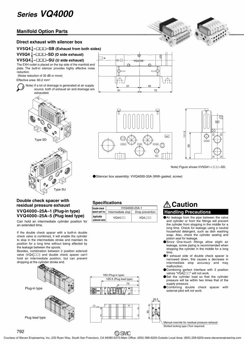
Effective area: 60.2 mm2
72
4551
91
VQ4100
R1
111.
5
PE
R2
SMC
12
59
SMC
A
5 1 P 3
X
2 B
4 A
CautionHandling Precautions
SpecificationsVVQ4000-25A-1
12
LOCK
PUSH
73
26.5
50
Manifold Option Parts
Silencer box assembly: VVQ4000-33A (With gasket, screw)
VV5Q4 ––SB (Exhaust from both sides)
VV5Q4 ––SD (D side exhaust)
VV5Q4 ––SU (U side exhaust)
151515
Direct exhaust with silencer box
The EXH outlet is placed on the top side of the manifold end plate. The built-in silencer provides highly effective noise reduction. (Noise reduction of 35 dB or more)
Note) If a lot of drainage is generated at air supply source, both of exhaust air and drainage are exhausted.
Type SD
Type SU
Double check spacer with residual pressure exhaustVVQ4000–25A–1 (Plug-in type)VVQ4000–25A–5 (Plug lead type)Can hold an intermediate cylinder position for an extended time.
If the double check spacer with a built-in double check valve is combined, it will enable the cylinder to stop in the intermediate stroke and maintain its position for a long time without being affected by the leakage between the spools. Besides, combination between 2 position solenoid valve (VQ41
2) and double check spacer can’t hold an intermediate position, but can prevent dropping at the cylinder stroke end.
Plug-in type
Plug lead type
Note) Figure shows VV5Q41––SD.
Double checkspacer part no. Intermediate stop
VQ44
Drop prevention
VQ4 Applicable solenoid valve
163 (Plug-in type)
125.5 (Plug lead type)
Manual override for residual pressure exhaust Slotted locking type (Tool required)
Air leakage from the pipe between the valve and cylinder or from the fittings will prevent the cylinder from stopping in the middle for a long time. Check for leakage using a neutral household detergent, such as dish washing soap. Also, check the cylinder sealing and piston seal for leakage.
Since One-touch fittings allow slight air leakage, screw piping is recommended when stopping the cylinder in the middle for a long time.
If exhaust side of double check spacer is narrowed down, this causes a decrease in intermediate stop accuracy and may malfunction.
Combining perfect interface with 3 position valves “VQ4 ” will not work.
Set the cylinder load so that the cylinder pressure will be within two times that of the supply pressure.
Combining double check spacer with external pilot will not work.
35
792
Series VQ4000
P0759-P0850-E.qxd 08.9.1 2:58 PM Page 792
Courtesy of Steven Engineering, Inc.-230 Ryan Way, South San Francisco, CA 94080-6370-Main Office: (650) 588-9200-Outside Local Area: (800) 258-9200-www.stevenengineering.com

P=25
121244
16.5
43.5
50.5
L1
L2
R4.5
SM
CS
MC
SM
CS
MC
SM
CS
MC
SM
C
12
59
96.573
9144 62
15
PE
R2R1
SMC
3870
17.5
29
90ø118
149
26.5 38
50.5
P=
25
ø11890
149
PE
R2R1
SMC
17.5
53
1212
50.5
26.5 38
50.5
P=
25
SM
CS
MC
SM
CS
MC
SM
CS
MC
SM
C
59
96.573
15P
=25
44L
1L
2
3
5 3
2 x Rc 1/8(Pilot EXH port)
2 x Rc 1/21(P) port
AMC610-10Exhaust cleaner
BB
B
BB
AA
AA
AA
A
AB
AB
AB
AB
AB
AA
2 x G Rc 3/4Electrical entry
2 x Rc 1/8(External pilot port)
X
B2
A4
B2
A4
B2
A4
B2
A4
B2
A4
B2
A4
B2
A4
B2
A4
X
35
3 2 x Rc 1/8(Pilot EXH port)
2 x Rc 1/21(P) port
AMC610-10Exhaust cleaner
B
A
AB
AB
AB
AB
AB
AA
AA
AA
AA
BB
BB
XX
2 x Rc 1/8(External pilot port)
B2
A4
B2
A4
B2
A4
B2
A4
B2
A4
B2
A4
B2
A4
B2
A4
1
88
101
2
113
126
3
138
151
4
163
176
5
188
201
6
213
226
7
238
251
8
263
276
L1
L2
L nDimensions
99
106.544 629 9
R4.5
16.5
43.5
12
38
L1
L2
L n
1
88
101
2
113
126
3
138
151
4
163
176
5
188
201
6
213
226
7
238
251
8
263
276
L1
L2
L nDimensions
L1
L2
L n 9
288
301
10
313
326
11
338
351
12
363
376
13
388
401
14
413
426
15
463
476
16
463
476
9
288
301
10
313
326
11
338
351
12
363
376
13
388
401
14
413
426
15
463
476
16
463
476
VV5Q4 --CD (D side mounting)
VV5Q4 --CU (U side mounting)
1515
Manifold mounted exhaust cleaner
An adapter plate for exhaust cleaner mounting isprovided on the top of the manifold end plate. The exhaust cleaner collects drainage and oil mist (99.9% or more) and is highly effective for noise reduction.(Noise reduction of 35 dB or more)
Applicable exhaust cleanersAMC610-10 (Port size Rc 1)
Note 1) Exhaust cleaner AMC610-10 is not attached. (Order it separately.)
Note 2) Mount so that the exhaust cleaner is at the lower side.Note 3) For details about the exhaust cleaner, refer to Best
Pneumatics No. 6.
Plug lead typePlug-in type
Lead wire lengthL0: ≅ 600 mmL1: ≅ 1500 mmL2: ≅ 3000 mm
2n x Rc 1/4, 3/8, C8, C10, C124(A), 2(B) port
Rc 1/4: Rc 1/4 threadRc 3/8: Rc 3/8 threadC8: One-touch fitting for ø8C10: One-touch fitting for ø10C12: One-touch fitting for ø12
≅ 3.5163 (3 position)
140 (Single)149 (Double)
U side entry (LU)
Station number
U side
Manual override
Indicator light
D side
D side entry (LD)
≅ 21
5
D side mounting
Stations
1
······
······
······
······
···
2
3
4
5
6
7
8
n
D side
U side
155.5 (Single)164.5 (Double)178.5 (3 position) ≅ 3.5
Indicator lightManual override
≅ 21
5
D side mounting
U side mounting
2n x Rc 1/4, 3/8, C8, C10, C124(A), 2(B) portRc 1/4: Rc 1/4 threadRc 3/8: Rc 3/8 threadC8: One-touch fitting for ø8C10: One-touch fitting for ø10C12: One-touch fitting for ø12
D side
D side
U side
U side
Stations
1
······
······
······
······
···
2
3
4
5
6
7
8
n
U side mounting
Formula L1 = 25n + 63, L2 = 25n + 76n: Stations (Maximum 16 stations)
Formula L1 = 25n + 63, L2 = 25n + 76n: Stations (Maximum 16 stations)
793
Series VQ4000Base Mounted
SJ
SY
SV
SYJ
SZ
VP4
S0700
VQ
VQ4
VQ5
VQC
VQZ
SQ
VFS
VFR
VQ7
P0759-P0850-E.qxd 08.9.1 2:58 PM Page 793
Courtesy of Steven Engineering, Inc.-230 Ryan Way, South San Francisco, CA 94080-6370-Main Office: (650) 588-9200-Outside Local Area: (800) 258-9200-www.stevenengineering.com

Solenoid Valve Interface regulator
ARBQ4000-00-A-1
ARBQ4000-00-B-1
ARBQ4000-00-P-1
ARBQ4000-00-A-5
ARBQ4000-00-B-5
ARBQ4000-00-P-5
Regulating port
A
B
P
A
B
P
P A
P B
A EA
B EB
ARBQ4000
A B
1.0 MPa
0.05 to 0.85 MPa
Air
–5 to 60°C (No freezing)
M5 x 0.8
P
15 31 14
35 16 15
18 40 40
37 19 37
Specifications
How to Order
0.33 0.30 0.33 0.30 0.33 0.30
SMC
55.5
PE
1 P5 3 R2R1
218.5
SMC
B2
14750
12
4 A
25
59
Regulating port: A Regulating port: B Regulating port: P
Conditions Inlet pressure: 0.7 MPa
Flow Characteristics
ARBQ4000-00-A
00 200 400 600 800 1000 1200 1400 1600
1600
0.1
0.2
0.3
0.4
0.5
0.6
ARBQ4000-00-P (P A)
ARBQ4000-00-B
ARBQ4000-00-P (P B)
0.6
Pressure Characteristics
0.000.2 0.3 0.4 0.5 0.6 0.7 0.8 0.9 1
0.05
0.10
0.15
0.20
0.25
0.30
0.35
00 200 400 600 800 1000 1200 1400
1400
0.1
0.2
0.3
0.4
0.5
00 200 400 600 800 1000 1200 1400
0.1
0.2
0.3
0.4
0.5
0.6
00 200 400 600 800 1000 1200
0.1
0.2
0.3
0.4
0.5
0.6
0.7
0.7
0.7
0.7
Manifold Option Parts
Interface regulator (P, A, B port regulation)
Spacer Interface regulators can be placed on top of the manifold block to reduce the pressure of each of the valves.
ARBQ4000-00--1 (Plug-in type)ARBQ4000-00--5 (Plug lead type)
Interface regulator
Regulating port
Applicable solenoid valve
Maximum operating pressure
Set pressure range
Fluid
Ambient and fluid temperature
Port size for connection of pressure gauge
Mass (kg)
Effective area at supply side (mm2)S at P1 = 0.7 MPa/P2 = 0.5 MPa
Effective area at exhaust side (mm2)S at P2 = 0.5 MPa
Plug-in Plug lead Plug-in Plug lead Plug-in Plug lead
Note 1) Set the pressure within the operating pressure range of the solenoid valve.Note 2) Operate an interface regulator only by applying pressure from the P port of the base, except
when using it as a reverse pressure valve. When using it as a reverse pressure valve, P port regulation is not allowed to use.
Note 3) When using a perfect spacer, assemble a valve, a spacer regulator and a perfect spacer in this order to use it.
Note 4) When using in A port regulation, B port regulation by closed center, since there is a problem in its operation, please contact SMC.
Note 5) Dust tight /Low jetproof enclosure (IP65) is not available with interface regulator.
VQ40 (Plug-in type)
VQ45 (Plug lead type)
Out
let p
ress
ure
(MP
a)
Flow rate (l/min(ANR))
Out
let p
ress
ure
(MP
a)
Flow rate (l/min(ANR))
Out
let p
ress
ure
(MP
a)
Flow rate (l/min(ANR))
Out
let p
ress
ure
(MP
a)
Flow rate (l/min(ANR))
Conditions Inlet pressure: 0.7 MPaOutlet pressure: 0.2 MPaFlow rate: 20 l/min (ANR)
Inlet pressure (MPa)
Out
let p
ress
ure
(MP
a)
Set point
794
Series VQ4000
P0759-P0850-E.qxd 08.9.1 2:58 PM Page 794
Courtesy of Steven Engineering, Inc.-230 Ryan Way, South San Francisco, CA 94080-6370-Main Office: (650) 588-9200-Outside Local Area: (800) 258-9200-www.stevenengineering.com

VQ4100
How to Order Manifold
R 5 03
External pilot specifications
Pressure SpecificationsValve construction Metal seal Rubber seal
Operating pressure range
0.15 to 1.0 MPa(0.15 to 0.7 MPa)
0.2 to 1.0 MPa(0.2 to 0.7 MPa)
0.15 to 1.0 MPa(0.15 to 0.7 MPa)
0.2 to 1.0 MPa(0.2 to 0.7 MPa)
VV5Q41 06
How to Order Single Valves
N11 SA K
Cylinder portN7N9
N11
ø1/4"ø5/16"ø3/8"
VQ4100 T5 03
Thread type (P, R and A, B port)Rc
NPTNPTF
G
How to Order Manifold
RcNPT
NPTFG
VV5Q41 T08 03 FU1
VQ4000
How to Order Sub-plates and Options (Example)
NP 02
RcNPT
NPTFG
VVQ4000 TP 03
B
1
RcNPT
NPTFG
VV5Q41 T08 C8 FU1
External pilot port2 x Rc 1/8
External pilot portRc 1/8
Option
External Pilot Specifications Inch-size One-touch Fittings
International Thread Standards Other than Rc
When the supply air pressure is:• lower than the required minimum operating pressure 0.15 to 0.2 MPa,• opposite air supply (R port supply), cylinder supply (A and B port supply),• used for vacuum specifications (please contact SMC),
it can be used for external pilot specifications.Order a valve by adding the external pilot specification [R] to the part number.External pilot is available as standard for manifolds and options.
Internal/external pilot can be mounted in a manifold. Compatibility with universal porting is possible for the single, double and 3P
(excluding perfect spacer) types.
<Sub-plate> <Manifold>
Note) Possible to mix mounting of internal and external pilot
External pilotpressure range
Note)
Single
Double
3 position
Vacuum to 1.0 MPa
Note ) Values inside ( ) denote the low wattage (0.5 W) specifications.
Combination of manifold options shown below and external pilot specification is not possible.
Release valve spacer
Direct exhaust with silencer box
For exhaust cleaner mounting
Manifold with control unit
Double check spacer with residual pressure exhaust
VVQ4000-24A-D
VV5Q4––S
VV5Q4––C
VV5Q4–
VVQ4000–25A–
UD
15
Control unit model no.
Rc specifications are standard for all ports, however, NPT, NPTF and G are available for international markets. Add the appropriate symbol following the port size in the standard part number.
Valve with inch size One-touch fittings is shown below.
Cylinder portPort size
NilNTF
Cylinder portPort size Thread type (P, R and A, B port)
NilNTF
Cylinder portPort size Thread type (P, R port)
NilNTF
(Sub-plate)
(Option)
Port sizeThread typeNilNTF
How to Order Single Valves (Example)
795
Series VQ4000Base Mounted
SJ
SY
SV
SYJ
SZ
VP4
S0700
VQ
VQ4
VQ5
VQC
VQZ
SQ
VFS
VFR
VQ7
P0759-P0850-E.qxd 08.9.1 2:58 PM Page 795
Courtesy of Steven Engineering, Inc.-230 Ryan Way, South San Francisco, CA 94080-6370-Main Office: (650) 588-9200-Outside Local Area: (800) 258-9200-www.stevenengineering.com
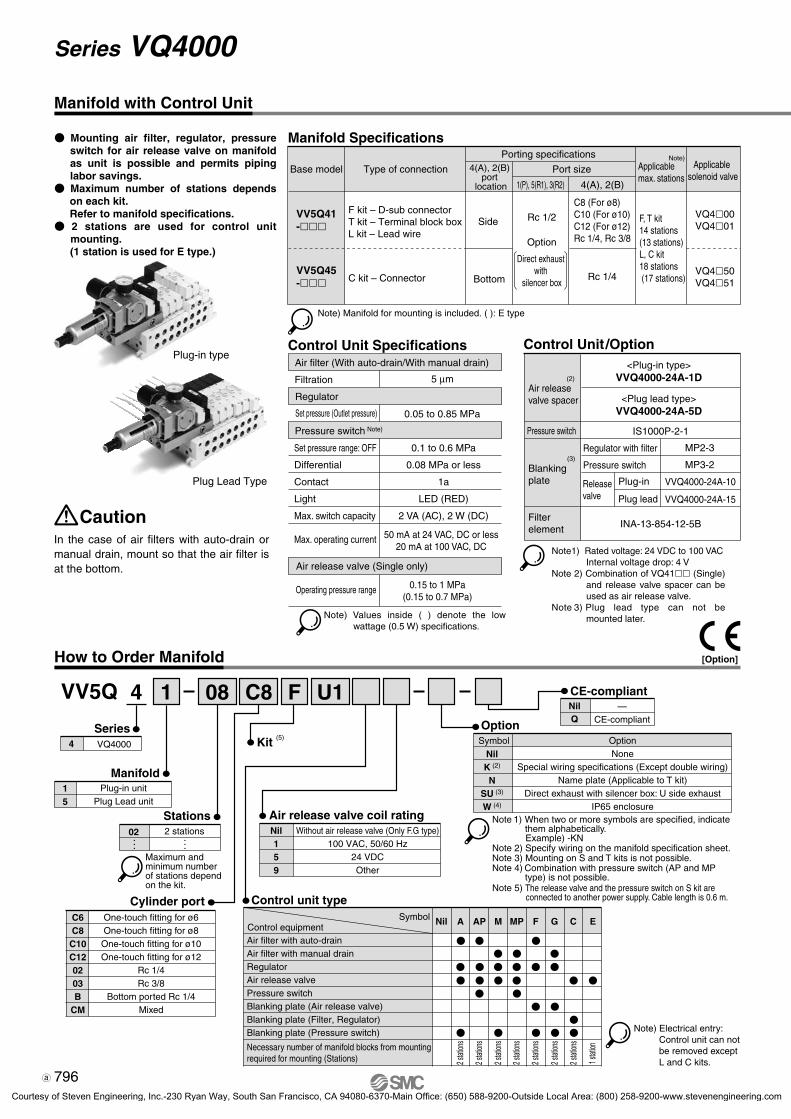
Manifold Specifications
Base model
1(P), 5(R1), 3(R2) 4(A), 2(B)
VV5Q
Manifold
Option
08 C8
C6C8C10C120203B
CM
15
1
Series4 VQ4000
4
Type of connection
Rc 1/4
Control Unit Specifications Control Unit /Option
0.05 to 0.85 MPa
0.15 to 1 MPa(0.15 to 0.7 MPa)
IS1000P-2-1
MP2-3
MP3-2
VVQ4000-24A-10
VVQ4000-24A-15
INA-13-854-12-5BCaution
F U1
Control unit type
A AP MControl equipment
Symbol MP F G C E
Air release valve coil rating
Manifold with Control Unit
How to Order Manifold
Mounting air filter, regulator, pressure switch for air release valve on manifold as unit is possible and permits piping labor savings.
Maximum number of stations depends on each kit.Refer to manifold specifications.
2 stations are used for control unit mounting.(1 station is used for E type.)
VV5Q41-
VV5Q45-
F kit – D-sub connectorT kit – Terminal block boxL kit – Lead wire
C kit – Connector
Porting specifications4(A), 2(B)
port location
Port size
Side
Bottom
Rc 1/2
Option
Direct exhaust with
silencer box
C8 (For ø8)C10 (For ø10)C12 (For ø12)Rc 1/4, Rc 3/8
Applicable max. stations
F, T kit14 stations (13 stations)L, C kit18 stations (17 stations)
Applicable solenoid valve
Note)
VQ400VQ401
VQ450VQ451
Note) Manifold for mounting is included. ( ): E type
Plug-in type
Plug Lead Type
In the case of air filters with auto-drain or manual drain, mount so that the air filter is at the bottom.
Air filter (With auto-drain/With manual drain)
Filtration 5 µm
Regulator
Set pressure (Outlet pressure)
Pressure switch Note)
Set pressure range: OFF
Differential
Contact
Light
Max. switch capacity
Max. operating current
0.1 to 0.6 MPa
0.08 MPa or less
1a
LED (RED)
2 VA (AC), 2 W (DC)
50 mA at 24 VAC, DC or less20 mA at 100 VAC, DC
Air release valve (Single only)
Operating pressure range
Note) Values inside ( ) denote the low wattage (0.5 W) specifications.
Air release valve spacer
Pressure switch
Blanking plate
Filterelement
(2)
(3)
<Plug-in type>VVQ4000-24A-1D
<Plug lead type>VVQ4000-24A-5D
Regulator with filter
Pressure switch
Release valve
Plug-in
Plug lead
Note 1) Rated voltage: 24 VDC to 100 VACInternal voltage drop: 4 V
Note 2) Combination of VQ41 (Single) and release valve spacer can be used as air release valve.
Note 3) Plug lead type can not be mounted later.
Plug-in unitPlug Lead unit
Stations02 2 stations
•••
•••
Maximum and minimum number of stations depend on the kit.
Cylinder portOne-touch fitting for ø6One-touch fitting for ø8One-touch fitting for ø10One-touch fitting for ø12
Rc 1/4Rc 3/8
Bottom ported Rc 1/4Mixed
Kit (5)
Nil159
Without air release valve (Only F.G type)100 VAC, 50/60 Hz
24 VDCOther
CE-compliantNil —
CE-compliantQ
SymbolNilK (2)
NSU (3)
W (4)
OptionNone
Special wiring specifications (Except double wiring)Name plate (Applicable to T kit)
Direct exhaust with silencer box: U side exhaustIP65 enclosure
Note 1) When two or more symbols are specified, indicate them alphabetically.Example) -KN
Note 2) Specify wiring on the manifold specification sheet.Note 3) Mounting on S and T kits is not possible.Note 4) Combination with pressure switch (AP and MP
type) is not possible.Note 5) The release valve and the pressure switch on S kit are
connected to another power supply. Cable length is 0.6 m.
Nil
Air filter with auto-drainAir filter with manual drainRegulatorAir release valvePressure switchBlanking plate (Air release valve)Blanking plate (Filter, Regulator)Blanking plate (Pressure switch) Note) Electrical entry:
Control unit can not be removed except L and C kits.
Necessary number of manifold blocks from mountingrequired for mounting (Stations)
2 stat
ions
2 stat
ions
2 stat
ions
2 stat
ions
2 stat
ions
2 stat
ions
2 stat
ions
1 stat
ion
796
Series VQ4000
[Option]
VQ4000.qxd 10.11.25 9:47 AM Page 14
Courtesy of Steven Engineering, Inc.-230 Ryan Way, South San Francisco, CA 94080-6370-Main Office: (650) 588-9200-Outside Local Area: (800) 258-9200-www.stevenengineering.com
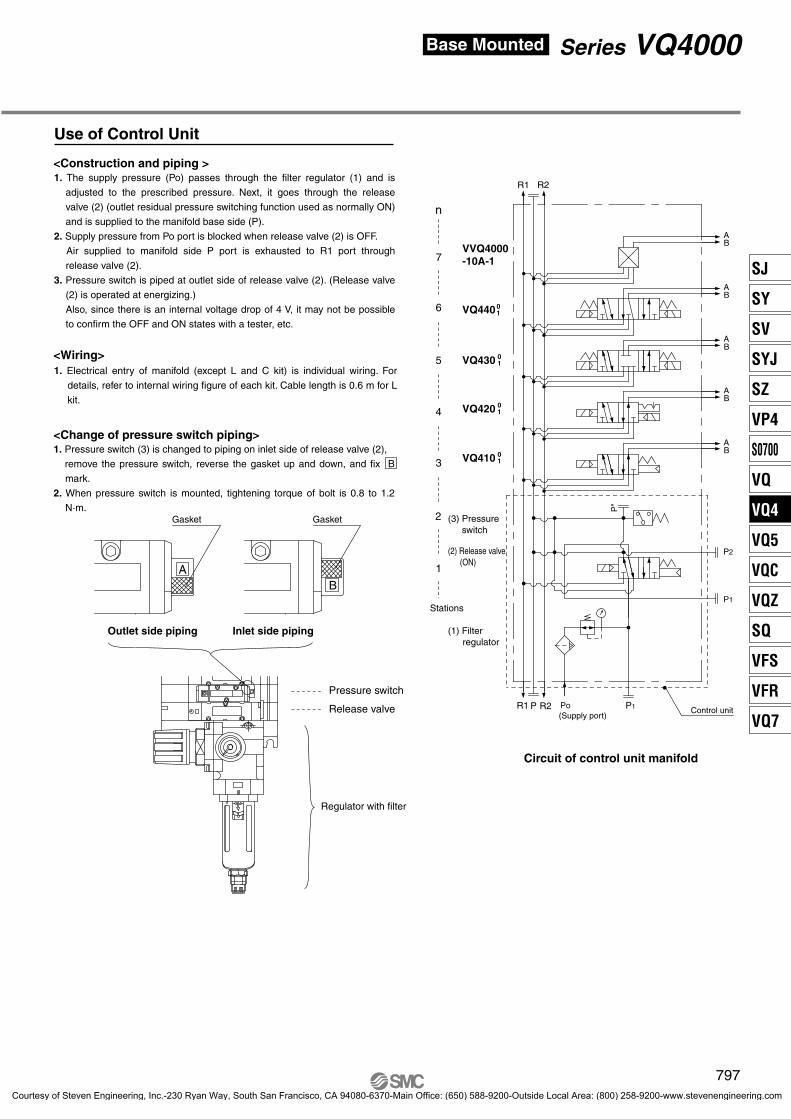
Use of Control Unit
R1 R2
R1 R2 P1Po
P"
P2
P1
VQ410 01
VQ420 01
VQ430 01
VQ44001
VVQ4000-10A-1
P
BA
BA
BA
BA
BA
BA
<Construction and piping >
<Wiring>
<Change of pressure switch piping>1. Pressure switch (3) is changed to piping on inlet side of release valve (2),
remove the pressure switch, reverse the gasket up and down, and fix B
mark.
2. When pressure switch is mounted, tightening torque of bolt is 0.8 to 1.2
N·m.
1. The supply pressure (Po) passes through the filter regulator (1) and is
adjusted to the prescribed pressure. Next, it goes through the release
valve (2) (outlet residual pressure switching function used as normally ON)
and is supplied to the manifold base side (P).
2. Supply pressure from Po port is blocked when release valve (2) is OFF.
Air supplied to manifold side P port is exhausted to R1 port through
release valve (2).
3. Pressure switch is piped at outlet side of release valve (2). (Release valve
(2) is operated at energizing.)
Also, since there is an internal voltage drop of 4 V, it may not be possible
to confirm the OFF and ON states with a tester, etc.
1. Electrical entry of manifold (except L and C kit) is individual wiring. For
details, refer to internal wiring figure of each kit. Cable length is 0.6 m for L
kit.
Gasket Gasket
Outlet side piping Inlet side piping
Pressure switch
Release valve
Regulator with filter
Stations
1
2
3
4
5
6
n
7
(2) Release valve(ON)
(3) Pressureswitch
(1) Filterregulator
(Supply port)Control unit
Circuit of control unit manifold
797
Series VQ4000Base Mounted
SJ
SY
SV
SYJ
SZ
VP4
S0700
VQ
VQ4
VQ5
VQC
VQZ
SQ
VFS
VFR
VQ7
P0759-P0850-E.qxd 08.9.1 2:58 PM Page 797
Courtesy of Steven Engineering, Inc.-230 Ryan Way, South San Francisco, CA 94080-6370-Main Office: (650) 588-9200-Outside Local Area: (800) 258-9200-www.stevenengineering.com

Plug-in type
PE
R2R1
12
SMC
SMC
SMC
SM
C
26.5
38
16.543.550.5
29
18
38
70(91)
163
30
6244
91
17.5
4270
.511
9
17
P0
50
SM
C
SM
CS
MC
SM
CS
MC
12
7396.5
15
42.5
50 50.5 L3
P=
2544
L1
L2
6
5 1 P 3
AA
AA
A
B
B
B
AA
BA
BA
B
9 9
X12
X
B2
A4
B2
A4
B2
A4
B2
A4
B2
A4
B2
A4
B2
A4
4 x Rc 1/25(R1), 3(R2) port
Rc 1/2(Supply port: Po)
2 x Rc 1/8(Pilot EXH port)
Blanking plate(MP3-1)
2n x Rc 1/4, 3/8, C8, C10, C12, 4(A), 2(B) port
2 x Rc 1/8(External pilot port)
18
øø
A
Manifold with Control Unit
(P1: Rc 1/8)
(P2: Rc 3/8)
(P1: Rc 1/2)
L1
L2
L n
Dimensions
L3
2113
126
332
(310.5)
3138
151
357
(335.5)
4163
176
382
(360.5)
5188
201
407
(385.5)
6213
226
432
(410.5)
7238
251
457
(435.5)
8263
276
482
(460.5)
9288
301
507
(485.5)
10313
326
532
(510.5)
11338
351
557
(535.5)
12363
376
582
(560.5)
(FU) Electrical entry from U side
U side
Manual override
Indicator light
Pressure switch(IS1000P-2)
Release valve(VQ4100-∗)
D side
AP: Auto-drain (INA-13-854DG)
MP: Manual drain (INA-13-854G)
Filter regulator
140 (Single)
149 (Double)
163 (3 position)
Stations
1
······
······
······
······
2
3
4
5
6
7
n
Rc 1/4: Rc 1/4 thread
Rc 3/8: Rc 3/8 thread
C8: One-touch fitting for ø8
C10: One-touch fitting for ø10
C12: One-touch fitting for ø12
Drain port
AP: ø10
MP: ø6
Plate assembly(VVQ4000 - 60A-1)
Electrical entry form D side(FD)
212.
5 (1
91: M
P)
≅ 106
Formula L1 = 25n + 63, L2 = 25n + 76, L3 = 25n + 282 (260.5) n: Stations
∗ L3 ( ): Type MP
≅ 18
5
798
Series VQ4000
P0759-P0850-E.qxd 08.9.1 2:58 PM Page 798
Courtesy of Steven Engineering, Inc.-230 Ryan Way, South San Francisco, CA 94080-6370-Main Office: (650) 588-9200-Outside Local Area: (800) 258-9200-www.stevenengineering.com

Plug lead type
PE
R2R1
12
SMC
SMC
SMC
SM
C
26.5
38
16.543.5
50.5
18
18
6244
17.5
4270
.511
9
17
P0
SM
C
SM
CS
MC
SM
CS
MC
12
7396.5
15
106.5
P=
2544
50.5 L3
L1
L2
5 1 3 3
AA
AA
A
BB
BB
AA
BA
BA
BA
X12
X
A2
B4
A2
B4
A2
B4
A2
B4
A2
B4
A2
B4
A2
B4
Pressure switch(IS1000P-2)
ø50 42
.5
50
Blanking plate(MP3-1) Plate assembly
(VVQ4000-60A-5)
4 x Rc 1/25 (R1), 3 (R2) port
2 x Rc 1/8(Pilot EXH port)
Rc 1/2(Supply port: Po)
6
9
L1
L2
L n
Dimensions
L3
2113
126
332
(310.5)
3138
151
357
(335.5)
4163
176
382
(360.5)
5188
201
407
(385.5)
6213
226
432
(410.5)
7238
251
457
(435.5)
8263
276
482
(460.5)
9288
301
507
(485.5)
10313
326
532
(510.5)
11338
351
557
(535.5)
12363
376
582
(560.5)
9
29
53 38125
2n x Rc 1/4, 3/8, C8, C10, C12, 4(A), 2(B) port
2 x Rc 1/8(External pilot port)
(P1: Rc 1/8)
(P2: Rc 3/8)
ø
(P1: Rc 1/2)
U side
Indicator light
Cable length(600 or 1500 mm)
Release valve(VQ4100-∗)
D side
AP: Auto-drain (INA-13-854DG)
MP: Manual drain (INA-13-854G)
Filter regulator
Manual override
155.5 (Single)
164.5 (Double)
178.5 (3 position)
Stations
1
······
······
······
······
2
3
4
5
6
7
n
Rc 1/4: Rc 1/4 thread
Rc 3/8: Rc 3/8 thread
C8: One-touch fitting for ø8
C10: One-touch fitting for ø10
C12: One-touch fitting for ø12
212.
5 (1
91: M
P)
Drain port
AP: ø10
MP: ø6
≅ 106
≅ 18
5
Formula L1 = 25n + 63, L2 = 25n + 76, L3 = 25n + 282 (260.5) n: Stations
∗ L3 ( ): Type MP
799
Series VQ4000Base Mounted
SJ
SY
SV
SYJ
SZ
VP4
S0700
VQ
VQ4
VQ5
VQC
VQZ
SQ
VFS
VFR
VQ7
P0759-P0850-E.qxd 08.9.1 2:58 PM Page 799
Courtesy of Steven Engineering, Inc.-230 Ryan Way, South San Francisco, CA 94080-6370-Main Office: (650) 588-9200-Outside Local Area: (800) 258-9200-www.stevenengineering.com

Rubber seal type
Component PartsDescription Material NoteNumber
Replacement Parts
VQZ111P--
Component PartsDescription Material NoteNumber
Replacement Parts
VQZ111P--
VQ4100
VQ4200
VQ4500
VQ4300
VQ4400
VQ4201
VQ4101
VQ4501
VQ4301
VQ4401
Plug-in Unit
Metal seal type
ABE
ABE
4 2
1(P)
5(R1)
(A)(B)
(R2) 3
(A) 4 2
5(R1)
(B)
(P)
(R2) 31
(A) 4 2
1(P)
5(R1)
(R2)
(B)
3
(A) 4 2
1(P)
5(R1)
(R2) 3
(B)
(A) 4
1(P)
5(R1)
(R2) 3
2(B)
4
(B)2
1(P)
5(R1) (R2)
(A)
3
4
(B)2
(A)
1(P)
5(R1) (R2)
3
4
(B)2
(A)
1(P)
(R1) (R2)
35
4
(B)2
(A)
1(P)
(R1) (R2)
35
4
(B)2
(A)
1(P)
(R1) (R2)
35
BodySpool/SleevePiston
Pilot valve assembly
Aluminum die-castedStainless steel
Resin
: Coil rated voltageExample) 24 VDC: 5
BodySpool valvePiston
Pilot valve assembly
Aluminum die-castedAluminum, HNBR
Resin
: Coil rated voltageExample) 24 VDC: 5
A: With A side lightB: With B side lightE: Without a light (Common for A and B)
A: With A side lightB: With B side lightE: Without a light (Common for A and B)
800
Series VQ4000Construction
P0759-P0850-E.qxd 08.9.1 2:58 PM Page 800
Courtesy of Steven Engineering, Inc.-230 Ryan Way, South San Francisco, CA 94080-6370-Main Office: (650) 588-9200-Outside Local Area: (800) 258-9200-www.stevenengineering.com

VQ4250
VQ4150
VQ4550
VQ4350
VQ4450
VQ4151
VQ4251
VQ4551
VQ4351
VQ4451
Rubber seal type
Component PartsDescription Material NoteNumber
Replacement Parts
VQZ111P--ABE
Component PartsDescription Material NoteNumber
Replacement Parts
Plug Lead Unit
Metal seal type
VQZ111P--ABE
4
(B)2
(A)
1(P)
(R1) (R2)
35
4
(B)2
(A)
1(P)
(R1) (R2)
35
4
(B)2
1(P)
(R1) (R2)
35
(A)
4
(B)2
1(P)
(R1) (R2)
35
(A)
4
(B)2
1(P)
(R1) (R2)
35
(A)
4
(B)2
1(P)
(R1) (R2)
35
(A)
4
(B)2
1(P)
(R1) (R2)
35
(A)
4
(B)2
1(P)
(R1) (R2)
35
(A)
4
(B)2
1(P)
(R1) (R2)
35
(A)
4
(B)2
1(P)
(R1) (R2)
35
(A)
BodySpool/SleevePiston
Aluminum die-castedStainless steel
Resin
Pilot valve assembly
: Coil rated voltageExample) 24 VDC: 5
BodySpool valvePiston
Pilot valve assembly
Aluminum die-castedAluminum, HNBR
Resin
: Coil rated voltageExample) 24 VDC: 5
A: With A side lightB: With B side lightE: Without a light (Common for A and B)
A: With A side lightB: With B side lightE: Without a light (Common for A and B)
801
Series VQ4000Construction
SJ
SY
SV
SYJ
SZ
VP4
S0700
VQ
VQ4
VQ5
VQC
VQZ
SQ
VFS
VFR
VQ7
P0759-P0850-E.qxd 08.9.1 2:58 PM Page 801
Courtesy of Steven Engineering, Inc.-230 Ryan Way, South San Francisco, CA 94080-6370-Main Office: (650) 588-9200-Outside Local Area: (800) 258-9200-www.stevenengineering.com

D side end plate assembly Manifold block assembly Tie-rod U side end plate assembly
The drawing shows a plug-in type.Note 1) The electrical entry cannot be changed.Note 2) Manifold block used is 2-station integrated type. For odd number of stations, 1 pc. of one-station manifold block is
combined at U side; for even number of stations, 2 pcs. are combined, therefore making the increase/decrease of stations possible.
D side U side
5 stations (Odd number)
Example)
6 stations (Even number)
2 stations2 stations 1 station
2 stations2 stations 1 station 1 station
1········2········3········4········5········6········Stations
802
Exploded View of Manifold
P0759-P0850-E.qxd 08.9.1 2:58 PM Page 802
Courtesy of Steven Engineering, Inc.-230 Ryan Way, South San Francisco, CA 94080-6370-Main Office: (650) 588-9200-Outside Local Area: (800) 258-9200-www.stevenengineering.com

VVQ4000 3A 1
VVQ4000 1
NilW (2)
VVQ40008. Tie-rods part no. (2 pcs.)
TR
AC
0203BC6C8C10C12N7N9N11
<Manifold Block Replacement Parts>
No.
456
Part no.
VVQ4000-80A-1
VVQ4000-80A-2
VVQ4000-80A-4
HNBR
HNBR
Number
10
10
10
Replacement Parts
VVQ4000Port size
50B
C6C8
C10C12N7N9
N11
DU
For D side entryFor U side entry
<D-sub connector assembly>
<SI Unit>
LF (1)
C
F1F2T1T2S1S2
L0L1L2
C
SI unit part no.
EX123 -SUW1EX123 -SUH1EX123 -SSL1EX123 -SSL2EX124 -SDN1EX124 -SCS1EX124 -SCS2EX124 -SMJ1EX240-SDN2EX240-SPR1EX240-IE1
Without SI unit16 output points Uni-wire System (NKE)SI unit for 16 output points Uni-wire H System (NKE)16 output points S-LINK System (Sunx)8 output points S-LINK System (Sunx)SI unit for DeviceNet (2 power supply systems)SI unit for 16 output points CompoBus/S (2 power supply systems) (OMRON)SI unit for 8 output points CompoBus/S (2 power supply systems) (OMRON)SI unit for CC-LINK System (2 power supply systems) DeviceNet (+COM)PROFIBUS DP (–COM)DI unit (For input) M12 8 number of inputs
SI Unit Part No.Model symbol
OF1HJ1J2QR1R2V
QWNW
Type
VVQ4000D side end plate assembly part no. (For input/output type for S kit)
3A 12∗ With connector on the SI unit
U side end plate assembly part no. (For input/output type for S kit)
UDUDUDUDUDUDUDUD
VVQ4000 2A 1
NilW (2)
CDSD
LF (1)
C
VVQ4000 2A 12∗ With connector on the SI unit
VVQ4000 19A
NilNTF
RcNPT
NPTFG
NilNTF
RcNPT
NPTFG
NilNTF
RcNPT
NPTFG
Description
Thread type Electrical entry
F, L, T, S kitF kit (Connector side)C kit (Plug lead type)
OptionNil
W (2)
CDSD
StandardIP65 enclosure
For exhaust cleaner mountingDirect exhaust with silencer box
<Manifold Block Assembly> 3. Manifold block assembly part no.
Type
For 2 stations (3)For 1 station
Thread type
OptionStandard
IP65 enclosure
Electrical entryF kit Double wiringF kit Single wiringT kit Double wiringT kit Single wiringS kit Double wiringS kit Single wiringL0 kit : Stations (1 to 16)L1 kit : Stations (1 to 16)L2 kit : Stations (1 to 16)C kit (Plug lead type)
Rc 1/4Rc 3/8Bottom ported Rc 1/4 (4)
With One-touch fitting for ø6With One-touch fitting for ø8With One-touch fitting for ø10With One-touch fitting for ø12With One-touch fitting for ø1/4With One-touch fitting for ø5/16With One-touch fitting for ø3/8
Stations: 02 to 18
Dedicated outputmodel
For in/outputmodel
<U Side End Plate Assembly Part No.> 2. U side end plate assembly no. (For F, L, S, T kit)
Electrical entryF, L, T, S kit
F kit (Connector side)C kit (Plug lead type)
Thread type
StandardIP65 enclosure
For exhaust cleaner mountingDirect exhaust with silencer box
Option
Description
Gasket
Gasket
Clip
Material
Stainless steel
Note) Spare parts consist of sets containing 10 pcs. each.
<Fitting Assembly> 7. Fitting assembly part no. (For cylinder port)
Applicable tubing ø6Applicable tubing ø8Applicable tubing ø10Applicable tubing ø12Applicable tubing ø1/4Applicable tubing ø5/16Applicable tubing ø3/8
Note) Purchasing order is available in units of 10 pieces.
Note 1) Tie-rods (2 pcs.) and lead wire assembly for station addition included.Note 2) Dripproof F kit is not available.Note 3) When ordering block assembly for L kit 2 stations, the lead wire
should be ordered by the smaller numbers of the D side (no. of station).
Note 4) Bottom ported type: For 1-station type only.
Note) When eliminating manifold stations, order this separately. When increasing manifold stations, it is not necessary to order since tie-rods are included in the manifold block assembly.
Note 1) D-sub connector assembly for D side: VVQ4000-19A-D is not included. (Order separately)
Note 2) Drip proof type for F kit is not available.
Note 1) D-sub connector assembly for D side: VVQ4000-19A-D is not included. (Order separately)
Note 2) Drip proof type for F kit is not available.
Port size
Exploded View of Manifold
803
<D Side End Plate Assembly> 1. D side end plate assembly no. (For F, L, S, T kit)
SJ
SY
SV
SYJ
SZ
VP4
S0700
VQ
VQ4
VQ5
VQC
VQZ
SQ
VFS
VFR
VQ7
P0759-P0850-E.qxd 08.9.1 2:58 PM Page 803
Courtesy of Steven Engineering, Inc.-230 Ryan Way, South San Francisco, CA 94080-6370-Main Office: (650) 588-9200-Outside Local Area: (800) 258-9200-www.stevenengineering.com

COM
COM
COM
A COM B T
COM
SOL.A
COM
SOL.B
SOL.A
COM
SOL.B
Warning
Caution
Caution
Caution
Push type (Tool required)
PUSH
TURN
LOCK
Proper tightening torque
0.8 to 1.2
Series VQ4000Specific Product Precautions 1Be sure to read before handling.Refer to front matter 58 and 59 for Safety Instructions and pages 3 to 7 for 3/4/5 Port Solenoid Valve Precautions.
Manual Override Operation
Since connected equipment will be actuated when the manual override is operated, first confirm that conditions are safe.Non-locking push type (tool required) is standard. As an option, slotted locking type (tool required) is available.
Bore ø5 Push down on the manual override button with a small screwdriver until it stops.Release the screwdriver and the manual override will return.
Locking type (Tool requied)<Option>
Push down completely on the manual override button with a small screwdriver. While down, turn clockwise 90° to lock it. Turn it counterclockwise to release it.
Bore ø5
Mounting of Valves
After confirming the gasket is correctly placed under the valve, securely tighten the bolts with the proper torque shown in the table below.
Mounting screw (M3)
Changing the One-touch Fittings
The built-in One-touch fittings on the cylinder port side are easily replaceable because of the cassette type. Clip prevents the fittings to come off. After removing the corresponding valve and take out the clip with a screwdriver, etc., then replace the fittings. About mounting the fittings, after inserting the fitting until it stops, then put the clip into the prescribed position.
Clip
One-touch fittings
Lead Wire Connection
Plug-in sub-plate (With terminal block) If the junction cover (1) of the sub-plate
is removed, you can see the plug-in type terminal block (2) mounted inside the sub-plate.
The terminal block is marked as follows. Connect wiring to each of the power supply terminals.
Terminal blockmarking
Model
3
6
VQ41001
VQ42001
VQ44500
1
A side
A side
A side
B side
B side
Note 1) There is no polarity. It can also be used as –COM.Note 2) Double wiring is used on sub-plate VQ410 . Applicable terminal 1.25-3S, 1.25Y-3, 1.25Y-3N, 1.25Y-3.5
01
Plug lead: Grommet typeMake connections to each corresponding wire.
Lead wire color Lead wire color
(–) Black
(+) Red
(–) White
(–) Black
(+) Red
(–) White
Single solenoid Double solenoid
Single solenoid Double solenoid
Standard
EnclosureIP65 compliant
Black: A side solenoid (–)
Red: COM (+)
Black: A side solenoid (–)Red: COM (+)
White: B side solenoid (–)
Black: A side solenoid (–)
Red: COM (+)
White: B side solenoid (–)
(Not used for single solenoid)
Green: (Not used for single or double.)
Note) There is no polarity. It can also be used as –COM.
804
P0759-P0850-E.qxd 08.9.1 2:58 PM Page 804
Courtesy of Steven Engineering, Inc.-230 Ryan Way, South San Francisco, CA 94080-6370-Main Office: (650) 588-9200-Outside Local Area: (800) 258-9200-www.stevenengineering.com

SOL
Varistor
Varistor Varistor
SOLSOL
SOL
COMSOL SOL
A B
Removal 1) Remove the mounting screw
that holds the pilot valve using a small screwdriver.
Installation 1) After confirming the gasket is
correctly placed under the valve, securely tighten the bolts with the proper torque shown in the table below.
Caution
Caution Caution
Caution
Installation/Removal of light cover Removal
Open the cover by inserting a small flat head screwdriver into the slot on the side of the pilot assembly (see drawing below), lift the cover out about 1 mm and then pull off. If it is pulled off at an angle, the pilot valve may be damaged or the protective O-ring may be scratched.
InstallationPlace the cover straight over the pilot assenmbly so that the pilot valve is not touched,and push it until the cover hook locks without twisting the protective O-ring. (When pushed in, the hook opens and locks automatically.)
O-ring
Light cover
Replacement of Pilot Valve
Light assembly
Mounting screw
B sideA side
Proper tightening torque (N·m)
0.1 to 0.13
For Plug Lead Type
Attaching and detaching connectorsTo attach a connector, hold the lever
and connector unit between your fingers and insert straight onto the pins of the solenoid valve so that the lever’s pawl is pushed into the groove and locks.
To detach a connector, remove the pawl from the groove by pushing the lever downward with your thumb, and pull the connector straight out.
Note) Do not pull on the lead wires with excessive force. This can cause faulty and/or broken contacts.
Connector
Lever
Internal Wiring Specifications
– (+)
+ (–)
Light circuit assembly(Orange)
DC: Single
A side – (+) B side – (+)
DC: DoubleA side lightcircuit assembly(Orange)
B side lightcircuit assembly(Green)
COM + (–)
AC: Single
Light circuit assembly(Orange)
A side B side
AC: Double
A side lightcircuit assembly(Orange)
B side light circuit ass’y(Green)
Enclosure IP65
Wires, cables, connectors, etc. used for models conforming to IP65 should also have enclosures equivalent to or stricter rating than IP65.
How to Calculate the Flow Rate
For obtaining the flow rate, refer to pages 44 to 47.
Mounting indicator
Note) The light circuit boards: A side is orange and the B side is green. It must be mounted on the pilot valve in accordance with the mounting indicators.
Note) For DC, coil surge voltage generated when OFF is about –60V. Contact SMC separately for further suppression of the coil surge voltage.
805
Installation and Removal of Light Cover
Series VQ4000Specific Product Precautions 2Be sure to read before handling.Refer to front matter 58 and 59 for Safety Instructions and pages 3 to 7 for 3/4/5 Port Solenoid Valve Precautions.
SJ
SY
SV
SYJ
SZ
VP4
S0700
VQ
VQ4
VQ5
VQC
VQZ
SQ
VFS
VFR
VQ7
P0759-P0850-E.qxd 08.9.1 2:58 PM Page 805
Courtesy of Steven Engineering, Inc.-230 Ryan Way, South San Francisco, CA 94080-6370-Main Office: (650) 588-9200-Outside Local Area: (800) 258-9200-www.stevenengineering.com

806
P0759-P0850-E.qxd 08.9.1 2:58 PM Page 806
Courtesy of Steven Engineering, Inc.-230 Ryan Way, South San Francisco, CA 94080-6370-Main Office: (650) 588-9200-Outside Local Area: (800) 258-9200-www.stevenengineering.com