Embed Size (px)
Citation preview

R A M C O N RAMCON BUILDING 223 SCOTT STREET MEMPHIS, TENNESSEE 3 6 1 12 TELEPHONE 901 / 4587000 800 / 456-4567
SOURCE SAMPLING for
PARTICULATE EMISSIONS - - NORTH EAST HOT MIX GO
--c
May 28, 1987
North East Hot Mix Company
5-:/ LLd G. Sumner Buck, 111 President
J . Cameron Mitchell Team Leader

I
I I R A M C O N
- I
RAMCON BUlLDtNG 223 SCOTT STREET MEMPHIS. TENNESSEE 361 12 TELEPHONE 90t 14567000 eoO/4%567
1 June 3, 1987
. . - Mr. Ron McGuirk Nopth East Hot Mix Div. of James Julian, Inc. P.O. Box 647 North East, MD 21901
Re: Particulate Emissions Test - Belair, Maryland
Dear Mr. McGuirk:
Enclosed are four copies of our report on the particulate emissions test we conducted at your plant. Based on our test results, your plant does not pass either EPA New Source Performance Standards or those set by the State of Maryland. The average grain loading of the three test runs was not in compliance with Federal or State Standards.
You will want to sign the report covers and send two copies to:
~ r f Craig Holdefer Maryland Air Management Div. of Environmental Affairs P.O. Box 13387 Baltimore, MD 21203
We certainly have enjoyed working with you and look forward to serving you again in the future,
G. Sumner Buck, 111 President
GSBIII: kr
Enclosures

TABLE OF CONTENTS
IV.
VI.
INTRODUCTION
TEST RESULTS
TEST PROCEDURES
THE SOURCE
EQUIPMENT USED
LABORATORY PROCEDURES & RESULTS
CALCULATIONS
FIELD DATA
CALIBRATIONS
RAMCON PERSONNEL

I. INTRODUCTION
- On May 28, 1987, personnel from RAMCON Environmental
Corporation (REC) conducted a source emissions test for
particulate emissions compliance at North East Hot Mix Company Is
CMI drum mix asphalt plant located in Belair, Maryland.
RAMCON personnel conducting the test were Cameron Mitchell,
Team Leader and John Bowden. Kim Rea was responsible for
the final particulate laboratory analysis including taring the
beakers and filters and recording final data in the laboratory
. . record books. Custody of the samples was limited to Mr. -
Mitchell and Ms. Rea. t
The purpose of the test was to determine if the rate of
particulate emissions from the plant's scrubber and the total
contaminants by weight (grain loading) are below the limits set
by EPA and the State of Maryland.
- - 11. TEST RESULTS
Table I summarizes the test results. The grain loading
limitation for EPA is -04 gr/DSCF and is specified in 39 FR
9314, March 8, 1974, 60.92 Standards for Particulate Matter (11,
as amended. The allowable emissions for the State of Maryland
is .03 gr/DSCF and is specified in C.O.M.A.R. 101806.03.
Mr. Craig Holdefer of Maryland's Office of Environmetnal Affairs
observed the testing conducted by RAMCON.

(2)
TABLE I
SUMMARY OF TEST RESULTS May 28, 1987
~ e i t Run - - Time
Grain Isokinetic Actual Loading Variation Emissions
Average: 0.0652 gr/DSCF 5.9 lbs/hr
On h e basis of these test results, the average grain loading of the three
test f uns was not below the -04 gr/DSCF emissions limitation set by US
EPA or the .03 gr/DSCF limitation set by the State of Maryland.
Therefore, the plant is not operating in compliance with State or Federal
Standards.
111. TEST PROCEDURES
A. Method Used: The source sampling was conducted in accordance with
Method 5 requirements of the U.S. Environmental Protection Agency as set
forth in 39 FR 9314, March 8, 1974, 60.93, as amended.
B. Problems Encountered: The plant had problems with the automatic
damper so the damper was manually operated. Because the flows were
less than expected, the sample volume on test run one is less than the
required 50 ft3. For test run two the damper was opened slightly to
increase the flow, but this caused problems with plant operations and the
minimum of 50 ft3 was barely attained. Therefore, the sampling time for
test run three was increased to 3.5 minutes per point for a total testing
time of 84 minutes to achieve the required minimum sample gas volume.
Runs: one and two were sampled for three minutes per point for a total
testing time of 72 minutes. All three test runs were conducted in one
day rather than the two day requirement due to a delay in starting the
test because of plant operations.

C. Sampling Site: T h e emissions tes t was conducted a f t e r a
s c r u b b e r on a round s tack with a diameter of 47.5". T h e
- sampling por ts were placed 47.5" down (1.0 diameters
upstream) from the top of t h e s tack and 95" up (2.0
diameters downstream) from t h e l a s t flow dis turbance ,
Twenty four points were sampled, twelve through each
t r ave r se for th ree minutes each.
Points on a
Diameter Probe Mark - *8 .Ow 10.2" 12.6" 15.4" 18,9" 23.9" 37.6" 42.6" 46.1" 48.9" 51.3" 53.5"
*Measurements include a
7. On standoff.

IV. THE SOURCE

IV. THE SOURCE
North East Hot Mix Company employs a CMI drum mix asphalt plant
which is used to manufacture hot mix asphalt for road pavement.
The process consists of blending prescribed portions of cold feed
materials (sand, gravel, screenings, chips, etc.) uniformly and adding
sufficient hot asphalt oil to bind the mixture together, After the hot
asphalt mix is manufactured at the plant, it is transported to the
location where it is to be applied. The hot asphalt mix is spread
evenly over the surface with a paver and then compacted with a
heavy roller to produce the final product.
T't following is a general description of the plant's manufacturing
prbcess: The cold feed materials (aggregate) are dumped into four
separate bins which in turn feed a common continuous conveyor. The
aggregate is dispensed from the bins in accordance with the desired
formulation onto the cold feed system conveyor to an inclined weigh
conveyor then to a rotating drum for continuous mixing and drying at
approximately 3000F. The required amount of hot asphalt oil is then
injected onto and mixed into the dried aggregate. The now newly
formed hot asphalt mix is pulled to the top of a storage silo by
conveyor. The hot asphalt mix is then discharged from the storage
silo through a slide gate into waiting dump trucks, which transport
the material to a final destination for spreading. The rated capacity
of the plant will vary with each aggregate mix and moisture content
wit5 a 5% surface moisture removal.
The drum mixer uses a burner fired with #2 fuel oil to heat air to
dry the aggregate, and the motion of the rotating drum to blend the
aggregate and hot asphalt oil thoroughly. The air is drawn into the
system via an exhaust fan. After passing through the burner and
the mixing drum, the air passes through a high efficiency scrubber.
The scrubber was manufactured by CMI. The exhaust gasses are
drawn through the scrubber and discharged to the atmosphere through the stack. The design pressure drop across the venturi is in excess of 8 inches of water. The particulate matter, which is removed by
the scrubber is fed into the scrubber pond where i t drops out of
suspension.


1. Aggregate bins: Virgin and recycled aggregate is fed individually into each of the bins by type. It is metered onto a conveyor belt running under the bins to a shaker screen. The proportion of each aggregate type is determined by the job mix formula and pre-set to be metered out to meet these
- specifications.
2. Preliminary oversize screen: The aggregate is fed through a , shaker screen where oversize rocks and foreign material is
screened out of the mix.
3. Weigh conveyor belt: The aggregate is conveyed to the rotary drum dryer on a conveyor belt which weighs the material, The production rate is determined by this weight reading.
4. Rotary drum dryer/mixer: The aggregate is fed into the rotary drum dryer where it is tumbled by flighting into a veil in front of a gas flame which drives off the moisture, Further
. . mixing is also accomplished in this drum. Hot liquid asphalt is injected approximately one-third of the way down the inclined - drum where it is mixed with the aggregate.
5. Burner: The fuel fired burner is used to dry the rough aggregate and sand in the rotating drum as well as reheat recycled asphalt when it is part of the mix.
6, Wet scrubbing system: A system of cyclonic action, spray nozzles and a venturi removes 99% of particulates in the gas stream.
7. Liquid asphalt storage: The liquid asphalt is stored in this heated tank until it is needed in the mixer. The amount of asphalt content and its temperature are pre-set for each different type job.
8. Conveyor to surge/storage bin: The finished product of aggregate mixed with liquid asphalt is conveyed to a surge bin. - -
9. Surge/storage bin: The asphaltic cement is dumped into this surge bin and metered out to dump trucks which pull underneath the slide gate at the bottom of the bin.
10. Control/operators house: The entire plant operation is controlled from this operator's house.
11. Truck loading scale: A s the trucks receive the asphalt from the storage/surge bin they are weighed on the loading scale which tells the plant operator the amount of asphalt that is
' being trucked on each individual load.
12. Mineral filler system (when used).
13, Burner fuel storage (when used).
14 . Stack.
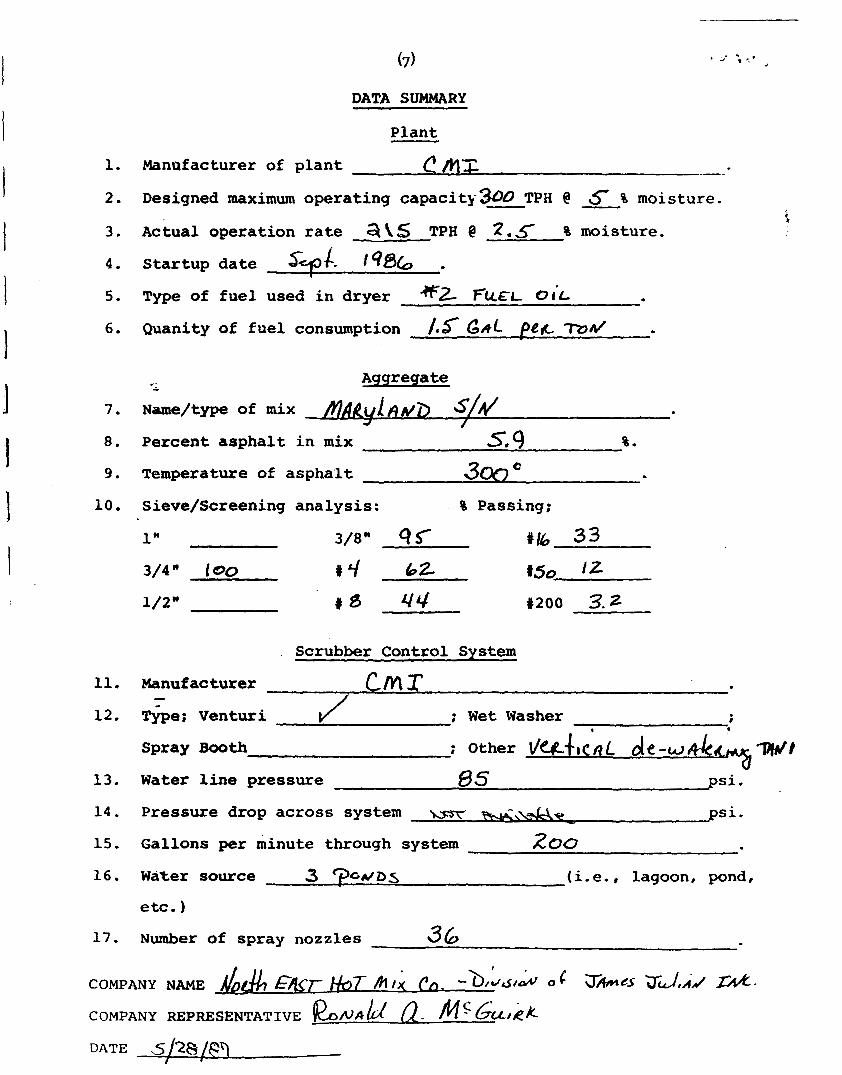
DATA SUMMARY
Plant
1. Manufacturer of plant c I V ~ X ---
2. Designed maximum operating capacity%~ TPH @ S % moisture. - - 3. Actual operation rate 5 TPH @ 2 . 5 % moisture.
4. Startup date ~ ~ 4 - 1 9 ~ 6 . a
5. Type of fuel used in dryer F~L€L 0 1 ' ~
6. Quanity of fuel consumption /.s GAL pe,l md
"- - Aggregate
7. ~ame/type of mix ~ R M D ~ / d 8. Percent asphalt in mix s.9 %.
9. Temperature of asphalt 3 ~ " *
10. ~ieve/Screening analysis: % Passing;
Scrubber Control System
11. Manufacturer C'.M T - 1
12. '&e; Venturi /' ; Wet Washer i 1 .
Spray ~ 0 0 t h ; Other I / U + B C ~ L dc-wf&- W? 13. Water line pressure 635 psi.
14. Pressure drop across system y~ G,L** psi. - 15. Gallons per minute through system ZOO 16. Water source 3 ? C A / ~ S (i-e., lagoon, pond,
etc.)
17. Number of spray nozzles 36
COMPANY NAME LH, g~7- HOT f i t * en. -~/;J/L oC ~ i h n d ~ JJI~,J ;J.
COMPANY REPRESENTATIVE &NAD Q. M%cL/ik DATE 5/28/fiV
/ I

(8) PLANT DATA

(9) PLANT DATA
COMPANY NAME
COMPANY REP. DATE PHONE #
DATA SOURCE
PLANT LOCATION
PLANT MFG. PLANT MODEL # PLANT TYPE
MIX SPECIFICATION # OIL SPECIFICATION #

V, EQUIPMENT USED

EQUIPMENT USED
Equipment used on conducting the particulate emissions test
was:
The Lear Siegler PM-100 stack sampler with appropriate
auxiliary equipment and glassware. The train was set up
according t o the schematic on t h e nex page.
An Airguide Instruments Model 211-8 (uncorrected) aneroid
barometer was used t o check the barometric pressure.
Weston dial thermometers a r e used t o check meter tem-
peratures. An Analogic Model 2572 Digital Thermocouple i s
used for s tack temperatures.
A Hays 621 Analyzer was used t o measure the oxygen, carbon
dioxide and carbon monoxide content of the stack gases. For
non-combustion sources, A Bacharach Instrument Company
Fyrite i s used for the gas analysis.
~ i l t e r s a r e mady by Schleicher and Schuell and a r e type I-HV
with a porosity of .03 microns.
The acetone i s reagent grade or ACS grade with a residue of
.001. -
Form #REC-07

VI, LABORATORY PROCEDURES & RESULTS
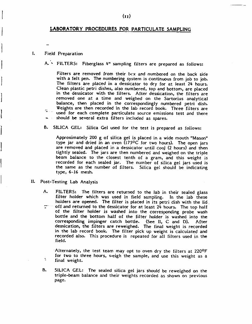
LABORATORY PROCEDURES FOR PARTICULATE SAMPLING
I. Field Preparation
A. - FILTERS: Fiberglass 4" sampling f i l ters a r e prepared as follows:
Fi l ters a r e removed from thei r t c x and numbered on t h e back side wi th a f e l t pen. The numbering system is continuous f rom job t o job. The f i l t e r s a r e placed in a dessicator t o d ry for at l eas t 24 hours. Clean plastic petri dishes, also numbered, t o p and bottom, a r e placed in t h e dessicator with t h e filters. After dessication, t h e f i l ters a r e removed one at a t i m e and weighed on t h e Sar tor ius analyt ical balance, then placed in t h e correspondingly numbered petri dish.
'I Weights a r e t h e n recorded in t h e l ab record book. Three f i l ters a r e - used for e a c h comple te par t icula te source emissions test and t h e r e - should be several e x t r a f i l ters included as spares.
0. SILICA GEL: Silica Gel used for t h e test i s prepared as follows:
Approximately 200 g o f si l ica gel i s placed in a wide mouth "Mason" t y p e jar and dried in a n oven (175OC for two hours). The open jars a r e removed and placed in a dessicator until cool (2 hours) and then t ightly sealed. The jars a r e then numbered and weighed on t h e t r ip le beam balance t o t h e closest t en th of a gram, and th i s weight i s recorded for e a c h sealed jar. T h e number of silica gel jars used i s t h e same as t h e number of filters. Silica gel should be indicating type, 6-16 mesh.
11. Post-Testing Lab Analysis
A. FILTERS: The f i l t e r s a r e returned to t h e l a b in thei r sealed glass f i l t e r holder which was used in field sampling. In t h e l ab these holders are opened. The f i l ter is placed in i t s petri dish with t h e lid .
r off and re turned to t h e dessicator for at l eas t 24 hours. The t o p half of t h e f i l t e r holder i s washed i n t o t h e corresponding probe wash bo t t l e and t h e bot tom half of t h e f i l t e r holder is washed in to t h e corresponding impinger c a t c h bottle. (See 11, C and D). Afte r dessication, t h e f i l t e r s are reweighed. The final weight is recorded in t h e l a b record book. The f i l ter pick up weight i s ca lcula ted and recorded also. This procedure is repeated for a l l f i l ters used in t h e field.
-Alternately, t h e test t e a m may op t t o oven d ry t h e f i l t e r s at 220°F f o r t w o to th ree hours, v ~ e i g h t h e sample, and use th is weight as a final weight.
B. SILICA GEL: The sealed silica gel jars should be reweighed on t h e triple-beam balance and thei r weights recorded as shown on previous page.

WEIGHING PROCEDURE - SARTORIUS ANALYTICAL BALANCE
The ,Sartorius balance is accurate to 0.1 mg and has a maximum capacity of 200 grams. The balance precision (standard deviation) is 0.05 mg, Before weighing an item, the balance should first be zeroed, This step should be taken before every series of weighings, To do this, the balance should have all weight adjustments at "zerow position. The beam arrest lever (on the lower left hand side toward the rear of the balance) is then slowly pressed downward to full release position. The lighted vernier scale on the front of the cabinet should align the "zero1' with the mark on the cabinet. If it is not so aligned, the adjustment knob on the right hand side (near the rear of the,. cabinet) should be turned carefully until the marks align, Now rettfrn the beam arrest to horizontal arrest position. The balance is now- "zeroedw.
To weigh an item, it is first placed on the pan. And the sliding doors are closed to avoid air current disturbance. The weight adjustment knob on the right hand side must be at wzeron, The beam arrest is then slowly turned upward. The lighted scale at the front of the cabinet will now indicate the weight of the item in grams. If the scale goes past the divided area, the item then exceeds 100 g weight (about 3-112 ounces) and it is necessary to arrest the balance (beam arrest lever) and move the lever for 100 g weight away from you. It is located on the left hand side of the cabinet near the front, and is the knob closest to the side of the cabinet. The balance will not weigh items greater than 200 grams in mass, and trying to do this might harm the balance. Remember -- this is a delicate precision instrument.
After the beam is arrested, in either weight range, the procedure is the same. When the weight of the item in grams is found, "dial .inw t h a t amount with the two knobs on the left hand side (near the 100 g lever) color coded yellow and green, As you dial the weight, the digits will appear on the front of the cabinet. When the proper amount is dialed, carefully move the arrest lever down with a slow, steady turn of the wrist. The lighted dial will appear, and the right hand side knob (front of cabinet) is turned to align the mark with the lower of the two lighted scale divisions which the mark appears between, When these marks are aligned, the two lighted digits along with the two indicated on the right hand window on the cabinet front are the fractional weight in grams (the decimal would appear before the lighted digits) and the whole number of grams weight is the arnobnt "dialed i n n on the left.
In general, be sure that the beam is in "arrestw position before placing weight on or taking weight off of the pan. Don't "dial in1' weight unless the beam is arrested. The balance is sensitive to even a hand on the table near t h e balance, so be careful and painstaking in every movement while weighing.

C. PROBE RINSINGS: In all tests, a probe wash-out analysis will be necessary. These samples are returned in sealed Mason jars and consist of A.R. Acetone with an unknown solid content. Clean 250 - ml beakers are used to make this analysis. These should be immaculately washed and rinsed with deionized water, then oven dried at IO5OC for about one hour. The beakers should be moved to
., the dessicator to cool for ninety (90) minutes, then labeled with a pencil and weighed on the Sartorius analytical balance. Any variance from this procedure should be duplicated exactly when reweighing, as this procedure has been found to be quite sensitive. After preparing the necessary number of beakers (one for each probe wash and one blank) the Mason jars should be opened, poured into the beaker, and any material remaining on the jar walls rinsed with an acetone wash bottle into the beaker- The amount of liquid in the beaker should be noted on the analysis form. The acetone rinsings are evaporated on a warming plate. The liquid i s kept swirled with an air sweep to
.-- - prevent "bumping". When the acetone is evaporated the beakers are
* weighed as in Section I1 A.
D- IMPINGER CATCH: In some testing cases, the liquid collected i n the impingers must be analyzed for solids content. This involves a similar procedure to the probe wash solids determination, except that the liquid is deionized water.
E. ACETONE: Conduct a blank analysis o f acetone in the 1 gallon glass container. This acetone will be used in the field for rinsing the probe, nozzle, and top half of the fi lter holder. Performing such a blank acalysis prior to testing will insure that the quality of the acetone to be used will not exceed the .001% residual purity standard.
SPECIAL NOTE - .. When sampling sources high in moisture content, (such as asphalt
plants) the fi lter paper sometimes sticks to the filter holder. When removing the fi lter it may tear. In order to maintain control of any small pieces of fi lter paper which may be easily lost, they are washed with acetone into the probe washing. This makes the f i l ter weight light (sometimes negative) and the probe wash correspondingly heavier. The net weight i s the same and no particulate is lost. This laboratory procedure i s taught by EPA in the Quality Assurance for Source Emissions Workshop at Research Triangle Park and is approved by EPA.

%
Sample Location - * Density of Acetom? (pa) .7853 wml Blank v01Ume (Va) ZOO ml
Date/Tine w t . blank 6 -1-67 Gross w t . !:.$!:; hte/T& w t . blank 6 - 2-54 7 Gross w t .
Ave. Gross w t . 8
Tare wt . 7% q+ 9: :, Weight of blank ,0002 w
Acetoneblank residueconcentration (Ca) (ca) = ( ~ ~ b ) / (va) (pa) = ( mg/g )
Weight of residue i n acetone wash: Wa = Ca Va& = ( I C 1 ( I = ( 1
- Acetone rinse volume (Vaw)
Date/Time of w t 4 -/- % 7 Gross w t
Date/Time of w t 6 - 2 - 8 7 Gross w t
Average Gross w t Tare w t
Less acetone blank w t (Wa)
W t of particulate in acetone rinse (ma)
Filter Numbers
Date/Time of w t //- q7 Gross w t
Date/Time of wt 6-2- $7 Gross w t
- Average Gross w t - Tare w t
Note: I n no &e should a blank residue greater than 0.01
mg/g lor 0.001% of the blank' weight) be subtracted from the sample weight.
Weight of particulate on filters(s) (mf) g A I f ( , Weight of particulate in acetone rinse 9 ,.oaso . oh31 Total weight of particulate (q,) 9 I 6 9 3 ,asi ' l
Signature of of reviewer
,201 '3-

COMPANY NAME d r f [ & c r
Chloroform and Ethyl Ether Extraction fo r EPA Method 5 (back half) - Relat ive humidity in lab 4 8 % Density o f chloroform and ethyl e t he r
1.473 9/,~ ,7129)'~~ RUN I RUN 2 RUN 3
Chloroform and ethyl e t he r rinse volume m l
Date/t ime of w t 6 - E -g 7 'I T$, Gross wt. g
Date/t ime of w t 6 - 8 -87 Y : 36 Gross wt. g
..- - Avg. Gross wt. g
Tare wt. g
Wt. of par t icula te in chloroform ethyl e ther r inse g
Water evaporation 11
-* r S Date/ t ime of wt. 6 - S - 2.-7 > PL, Gross wt. g
Date/ t ime of wt. 6 -8- 87 4 :3b ~ r o s s wt. g
Avg. Gross wt, g
Tare wt. g
Less chloroform & ehtyl e i the r blank wt. g
Note: In no case should a blank residue 0.02 mg/g o r 0.00196 of t h e weight of EFiEoform ethyl e t h e r used be subtracted f rom the sample weight.
Weight of par t icula te f rom wate r (mf) g 4
Wt. o f par t icula te in chloroform ethyl e t he r r inse g
Total weight of par t icula te (mn)
Remarks
127.90~3~
,,0001
Signatlire of Analyst
Signature of Reviewer
- 163.9433 lbz.7g.g
0109
4 017 1 &.oa80
,0171. 0 244 ,0426
.0/47 ,018 6 ,0333

ASH TEST DATE %/g7
il AFTER ASHING UN f - I I I 9. I +
RUN # BEFORE ASHING
Gross wt. after ash /30-74~9 / 40. bosq /3q. 7727 I -tale weight i 3 0 . 7 3 0 ~ 140 ssO(n I ? Q 9~z-i-
' weight ot non-volatiles
I
/ Gross Weight -tare weight
1 Net Weight of Particulate
1 . - -
I
/30.7534 130.730a
. oa32
2
140. 6 / 3 9 / ~ O . S S O ~
0633
Analyst Checked I 1
Approval
3
/3 9. 97 9 9 139. 9 5 3 2
0262-
CALCULATK)NS NON-VOLA'IILES ! U N U
Weight of on-voIatiIes
+ Net weight of - Particulate - X 100%
Weight percent of non-volatiles
I
8 0147
023% 100%
63-Ll
2
0548 .Oh33
100%
8&-6
3
,019s
m&a 100%
* / L f * c f

VII. CALCULATIONS -

NAME: NOF?TI-I EAST HOT H I X (17)
LOCATION: FELAIR, MARYLAND d a t e 5/28/87 5/28/87 5 / 2 8 / 8
SUMMARY C)F: 'rlfs'r T:IA'I'A RUN H I RlJN ## 2 RUN U
4 I s o k i n e t i c v a r i a t i o n I: 96 5'4 1 0 1
3 Sample g a s VOIUIIIP . . -rnetet . ' c o n d i t i o n s , c f . Vm Lb5.99 53.83. 5 6 . 0 4 P
I Auerayq,- metel- ternperatu l -e , R 7'm r r r l JJ;" 557
I - 576
7 Average 0,- i f a c e p i -essure d r o p , i n .l-+,.,a A 1.4 1,15 1.48 1.21 i i
8 T o t a l p a r t i c u l a t e collected m q , M 1.i 169.2 251 , 7 2 0 1 . 2 1 I VELOCITY TRAVERSE D A T A
Parometr - I c p i - e s s v . r e , i n . klg. Pk! a I-
A v e r a g e a b s o l u t e s t a c k t e m p e r a t u r e , I? 'i' 5. .--.-- -.- ---.---- .- ....
A v e r a y e - ' : . /vet o c i t r h e a d ( C p = '80 ) - \ i h P
A v e r a g e s t a c k g a s v e l o c i tr f t . / s e c , '-4
T o t a l w a t e r c o ! l e c t e d b y P i -a in , m ! , V i c
M o i s t u y i n s t a c k g a s , X E{ w s
EMISSIONS I I A T A :
S t a c k gas f l u w i - a t e , d s c f i h r , !:OqO's) W5cl ... T o t a l p a r t i cLk!d.ke c c j n c e n t 1 - a t i o n , gr1cl5c:f !... s
T o t a l l : ) a y i : i c \ r ! a . t e cortcefit i . .a.! . ion, !k.i::../'hy E
T c t a I pat. ' .kjc:!l!s .[p r::~i . ,c:e~.i . I .v.a-i . ion, [!:>i;,./'mb2.u E I

(18) Tlry G a s Vcllllnie :
T fli
-- V,s l ( s . l d i
- Iii-y Gas. Vo lump t h r a u g h fiie.tey a t s t a n d a r d cond i t i o n s , c u . f t .
'.,,I - frl - D r y Gas V o l u , ~ ~ e r~iea.:ui-.ed b y nte.i.ei-, cu: f t ,
.- r'b a ,- - B a r o m e t r i c p r p s s ~ i - p a f o r i f a c e m e t e r , i n , ~ 9 .
..- F? -
s t d S t a n d a r d a b s a l u t e p r e s s u r e , (ZC?. 92 i n , tdg, ) ;.L
T m = Abso t u t e t e i n l 3 e r a t u l - e a t r r ~ e t c r - R
'f = S t a n d a r d d b s o I l1.t.e .I.e,ll!:jei.a-tu.ye < 5 2 9 - p i s .!. d
- - ..
Run # 2 Y := 1. '7 , <) :.I. ( , j i 5 3 , 9 1 ) 1.48 fn I s .r: cl 3 < 3 g , 1.1. 6 ) .{- .- .-. .-. -
13.4 ............ .................................. i .._.
56.7 ....... ....
- 5gsc:.& dsi;

Tots c(:lIita.i n a n t s by we i c ~ h t : ' G R A I N LOADING'
= =: T o t a t amount o f p a r t i c u l a t e m a t t e r c o l l e c t e d , m c ~ .
Run # 1 :

Dry m o t e c u l a r w e i g h t :
XCO, = Pei-c:enZ c a r b o n d i o x i d e b y vo lume idv.:: basis>. ...
xu ... -. .- -. - P e r c e n t ox:- . [~en b y v o l u m e ( d r y basis). 2 n/
+., ./. t-4, = P e r c e n t n i t r o g e n b y v o l u m e ( d r y basis)
Tr .2&4 -. R a t i o o f 0, . ta N,, i n a i t - , v / v , i i.
0 ' 3 2 = t . l u \ e c : u i a r w e i i j l . ~ . ! o f O,, d i v i d e d b y 1 0 0 , .L
0.44. = M o l e c u l a r t , ~ e i g l r . t o f GO,. d i v i d e d b y i O Q . F
-%. Run ## 1 : M d == (j,l.l.l.t(lj.,lfi:: ) .+ @ , 3 2 ( 9 , Q X ) .t. 0 . 2 2 1 , Q % +. 8 0 . 0 % ) -... .2 ij , 1 i. b , / i. . ...-in0 E
Run ## 2 : Md = 0.4.4(12.1% ) + O,32(1.0.0% ) c 0.28< , O X c 1 7 , 9 X i = :<0.3 ! b , .:.' ! !:I . {!\ 0 \

Water vapor condensed : (21)
R 'I' I s t d :j ... .- .- -. .... -.... ................... i'4
!J " < yi .k d j
b' = Vo!ufne o f wa.!:.e!- v a p o r - c:c!nc!pnsecl <!jfarjl-Jaj..cJ i::orjdi'!. ic~y~s: ) s c f . W C S f d
id :=: Vctluiljc o f i,ra.ieu. vapor c o ! ie t : : . t i? t j i i . 1 ~ j i [ j i - : l gi.,! <.s.tc3n{ii$+-i:j i -~:t , - ,<j i~i i i j~-,~:.) ...... !,.I5 g .t (j :I F - i n a i uoluaie o f impirigei- roritpi.i. i .s, ji!!,
V . I
= I n i t i a l crolutrte i1.f impingei- r::orr.l:~.r~fz.
P = D e n s i t y o f w a t c r , C0,002201 I b / m ! ? ,
I? ::: I d e a I gas con!;.tal.i!., 21 .a5 I i n . I - l c ~ , ) i ~ i . 1 , f t . i i b , -(no t e ) ! 'F!)
Pi Id
= M o l e c u l a r w e i g h t o f wa.l.ei- vapor (18,0 ! b i ! b - - n l o ! e ) .
.rst (j = +&solute t e m p e r a t u r e a t s t a n d a r d cond i t ion^., 5 2 8 " ~ ~
(j - A b s o l u t e pr.er.r;ure a t s . tandard cnndii:lc,i.i!;, 2 9 , ? 2 i n c h e s ~-.;cJ.
Rrrri # 2 : ' Vwc(:s?.r:l j = i 0 . 0 4 7 0 7 ) ( 4 1 2 . 0 ) == 19.4 C:U, f . t V = I , . '7 1 . ; j C 2 1, , 0 1) t:: h.isCJ(st(jj 3. . u {: u . .f .!.

1 M o i s t u r e c o 1 3 l e n . l . o f s t a c k g a s e s :
.+. ',.' v , , ( I r t x 1 0 0 5 .I. CI "."Jr-td ...... .......... ......... .. B : -.. .- ̂ ..". .- ""-. -- -.- .- - -. - --
I,) ti:. V .+. ',,t I.1 CI I.#] y; <J ._;I. d 5. .t d '+ m
5 P cl
27.4 .+- ..., , i
. R u n # 3 : B - ...-..........-..... .Y ! :::: 3 5 , 1. % US 27.11. .t , '7 +. I:- .,) .# .L . 9 2
M o i e c u l a r u e i y h t o f s t a c k g a s e s : i"g = M d (1-8 j + j.8 (E > .
WE; W r : - l113 e 1'. e : -
cl = t . l@!ecu!ar w e i g h t 01 s i t a c k qa:;, d r y 5 , i t b , . , , ' l [ - : l . . . - m ~ { e j ,
.... R u n ?Z 1. : M,.. z 3 0 . 1 , (1 ,311.8 ;) -+. < , 3 4 8 j .... ... '-slr ..I , ?a . r ! b , / ! t! ....- ra !:# 1 e :' ,.. ....
Rtnn tt 2: = 301.3 (I-- ,28'7 :i -+. 11, 8 i , 28 -,;- ) :=: ' 5 &. ,:. . i ) ,.! i' .. t t 1:) . ../' 13 . ....ill (:, ! e ji ....

F' s t d
..-..- - = A v e r r s e v e l c ~ a i t y of g a s s t r e a m i n s t c c h , f i : , / / s e c ,
. . k: , '..
..- - V e l o ( : : i - t r h e a d o f : i t a c i ~ ga s , i n : !..i,,,n, a,.
.... .... ................ 'I' c j ( a v 9 . 5
-..
1:' ?:;.
-.. - Bdj"Qibp. t j i ! : pj"e:.elrie a t m p ~ ! i i ~ , ~ y . e ( ~ , p f i + r i . k p I < i l l , t . ! g ! ,
:= S t a c k s t a t i c ~ ) r . e s s u r . e ( j rt .I-!y:i ,
..- -- A b s o ! u t e s t s c k gas p r e s 5 ~ l - e ~ i in.l.fpi =: p h3i-+. Pg
= S t a n d a r d a b s o l u t e p r e s s u r ( 5 , ( 2 9 . ~ 2 in,^^ 1 ,
" S t a c k t e m p e l - a t u i - e l C G f i ,
A b s o l u t e s t a c k t ~ m p e r s t u r t . , ( ' R ) , =;: q,dg + t - 5 ' - - - n o J . e c u l a r w e i r h t o f s t a c k 4as , hasis, ( ! b , f ~ b . - , l , o ~ p ; ,

Stac:k ga!j f l o w r a t e :
W h e r e :
:=: D r y uut .u ,net i - ic . . stac:k g a s . f l o w i - a t e c o n - e c t e d t o s t a n d a l - d cor jd i 4 i n n s , i d s c f f l r r 1 , .. :?
= -;Cro.;z 5 e c . t i ona [ a t p a o f s t a c k ( f ' k , } ,
* := C o r i l ~ e r s i o n f a c t o r , sec : . /h i - .
.- -. R u n # 1 :
:360[1 1'1....,348) < 2 3 . 5 2 ) 1 12 , s ) Q,d
...... .." -- .- ""
, .- -. .- .. 3 I! . '4 $5
--....- I? r c- ..... ,~?,&35 ( jscf / r.) A. r . 9 , 1 7 ? ') d-

(25)
Emiss ions r a t e f r o m s t a c k :
( C 5 ) ! QCjd) .... .... E ........ .... ........ .... ".. -- .-. .-. .-. -. .- I b . /' 1.i~. ,
W t i t!r e :
9 = Ill-r v o \ u i n e . l . r i c s t a c : k gas ? I O U r a t e c o r r e c t e d t o s % a r i d a r d c: (>ndi .I. i o r i s , ~ d s c : f / l ~ r ~ ,
<,0365! c 700347) ................... ..... Run # 2 : E - - .-. "- .--.... ...-..--.. "..-"-".- -. --
70 0 0

V . = . i 'o2a! volume of l i q u i d c c l ! l e c . t e d iri inipinqe\- . i a n d . r i ! i c a g e l , rn i C: ..... T - Absolu.I .e a v e r a g e d r y g a s rrieti?i- - teit ,pel . .atu~c?, O R . m
1:' * .: E(ai-Gb,,l(?.i.i-ic pr-.ec.sure a t s a m p l i n q ~ . i t e , < i r 1 , 1 4 g j .
b a r
i' - - S t a c k y . 5 =is v e l o c i t y , f i ,/set, - Abso s t a c k g a s p r e s s u r e , i n , !.lg.
f i 5 ~ i - 0 5 s s e c t i o n a t a r e a o f n o z z l e , f t 2 .

VIII. FIELD DATA


IX. CALIBRATIONS

METER BOX CALIBRATION DATA AND CALCULATION FORM
(English units)
Date &dx7 Heter box number Lqb9~3~ -----
Barometric pressure , Pb = *.\\ i n . Hg Cal ibra ted by '8.- -
a I f t h e r e is only one thermometer on t h e dry gas meter, record t he temperature uride r t
d -
O r i f i c e manometer
s e t t i n g (MI,
i n . H ~ O -2 -
0.5
AH, in. I? 0
2
0.5
1 .0
1 .5
2 .0 - 3.0
4.0
Q u a l i t y Assurance Handbook M4-2.3A ( f r o n t s ide)
Time (e),
min
Form #1tEC-02
, - 13.6
- 0.0368
0.0737
0.110
0.147
0.221
0.294
'i
,\Sy\B\ 1 .o
1.5
2.0
3.0
4.0
Gas volume
M@i in. H20
\> \w3 \m"s
Temperature Wet t e s t
meter (Vw),
f t 3
Vw Pb(td + 460) - -
'i AH Vd(Pb + ( t + 460)
\3\ \!Y\
Wet test meter (tw),
OF
5
Dry gas meter (Vd) 9
f t 3
5 w-
(t + 460) O 2 - 0.0317 , [ ; ] -
m@i Pb (td + 460)
10
10
10
10
Dry gas meter
&
\33\
/&&'QY
Avga ( t d )
OF
I n l e t (td 1,
i OF
Out le t ( t d 1,
o OF

POSTTEST DRY GAS METER CALIBRATION DP;TA FORM (English units)
a I f there i s only one thermometer on the dry gas meter, record the temperature under t d
-
Test number Date 4 - 3 0 - 47 Xeter box number 3 Plan t c
B a r o m e t r i c p r e s s u r e , ~ ~ = 7 9 ~ ~ / , , i n ~ g ~ r y g a s m e t e r n u m b e r 6 ~ F $ ? 6 , , . pretest^ 079 I
where 3
Vw = Gas volume pass ing through the wet t e s t meter, f t . * Vd = Gas volume passing through the dry g.8 meter, f t J .
tw = Temperature of t he gas i n the wet t e s t meter, OF.
' Y = * J F
V ~ C U ~ s e t t i n g ,
i n . Hg
5 4 5
Time ( 8 ) , min
15.5 177 3
Or i f i ce manometer s e t t i n g ,
(AH) , i n . H20
t = Temperature of t he i n l e t gas of t he dry gas meter, OF. d,
L
td = Temperature of the o u t l e t gas of the dry gas meter, OF.
0
'i
. 9 9 ? /*003 ,999
td = Average temperature of t h e gas i n the dry gas meter, obtained by t h e average of td and td , OF. i o
AH = Pressure d i f f e r e n t i a l across o r i f i c e , i n . H20.
Yi = Ratio of accuracy of wet t e s t meter t o dry gas meter f o r each run. Y = Average r a t i o of accuracy of wet t e s t meter t o dry gas meter f o r a l l t h r ee runs;
to le rance = p r e t e s t Y $O.OSY.
i
Vw Pb ( t d + 460)
ty + 46 ( ( 13.6 9 1,3Y /. V Y
/ * 3 6
Gas volume
Pb = Barometric pressure , i n . Hg.
8 = Time of c a l i b r a t i o n run, min.
Temperature Wet t e s t
meter (V,,,),
f t 3
10
10
10
Quality Assurance Handbook M4-2.4A
Wet t e s t , meter (tJ,
O F
Dry gas meter (Vd) , f t 3
/Pa 7, /01 /o. z
Dry gas meter I n l e t (td 1,
i O F
76 7 ? $6
Out le t t 1,
o O F
/OV
/Q 0
/oo
Averagg ( t d ) ,
OF
$5 90 yc

- Lear S i e g l e r Stack Sampler
Heacing Probe C a l i b r a t i o n
Probe No. - 5% Probe Length . - . - - - - , - - - - - - - - . - - - - "if\ -
Date o f C a l i b r a t i o n \ Signature - '%L-A, sa-~uu&L -- Name of Company to b e t e s t e d -
Note: 3 i t . probe - 5 min. warmup
C.: - 6 f t. probe - 15 min. wamup 10 i t . probe - 30 min. warmup
+% C a l i b r a t i o n f l o w r a t e = - 7 5 CFM

STACK TEMPERATURE SENSOR CALIBMTION DATA FORM
a Every 30°C (5O0F) for each reference ~ o i n t .
b ~ y p e of-- ca l ibra t ion system used. c[(ref temp, O c + 273) - ( tes t thermom temp, OC + 27311
ref temp, OC + 273 loo< - 1.5%.
-
Date Thermocouple number 51 Ambient temperature oc ~ a r o m e t r i c pressure i n - H1
Calibrator plr\uuPa Reference: mercury-in-glass other
J
Q u a l i t y Assurance Handbook M2-2.10
Reference point ,
number <- - -
4
C
sourceb ( s p e c i f y )
'Lco -%c
u&...
Temperaturec d i f ference ,
%
Reference thermometer temperature,
OC
3xY-
a\x F
\\Q- f
Ly F-
Thermocouple potentiometer temperature,
OC
Y\x0 F
I \&,%A SQO 7
- 5.7 6-47 7 Z*P

PITOT TUBE CALIBlUTION DATA
Calibration p
Type S pitot
q 8 ID number size (OD) itot tube: type
tube ID number .-- CP(std) - - I
date \ - 7 ~ 6 ~ performed by , &'/ /A,,
D APs 1 a DEV . AP,tdl cm (in.) cm (in.) C ~ ( s )
H2° . 61 H2° I .74 I . 3 I ot3
. r?.z- I / , I s 4
I - 8 0 ,& . 74 % - . 4 a ! 1 . q5 I
_C -
-- __C
I w --- I
I I
I - I
Average I d \ I - ?o -
side calibration
apstd' APs' a DEV . b cm (in.) cm (in.) C ~ ( s ) H2° H2°
1 . 3 - 7 9 .0\ * 5 2 ?b I ,oo 1.1' I
1 1,4< 60 I ,oo 8
I
I Average 80
7
b~~~ = c ~ ( ~ ) - P ' (must be 10.01)
ep(~) - Ep(~) = (must be <0.01). - ~uality Assurance Handbook MZ-2.5

STACK TEMPERATURE SENSOR CALIBMTION DATA FORM
- 6 - / q -86 Date Thermocouple number
~ l b i e n t temperature 3 V oc ~ a r o m e t r i c pressure 29- 6 i.'. H. 5 -
Cal ib ra to r ( 0- Reference : mercury-in-glass J
other
a ~ y p e of c a l i b r a t i o n system used.
e m , OC + 273) - ( t e s t thermom temp, OC + loor l~%. r e f temp, OC + 273
Qual i ty Assurance Handbook M5-2.5
Temperatureb d i f ference ,
%
0
C-;
C'
8 ,,
Thermocouple potentiometer temperature,
OC
3 P , g y --
Reference thermometer temperature,
OC
Reference p o i n t
number - - i
A
sourcea ( spec i fy )
I w I + e
a F't< c J+
e
e
- -
, 0'~
5.7647 7z0;

- Date 26 Thermocouple number
Ambient temperature $ '1 O C ~arometr ic pressure > g ( ? r i n . ~g
Calibritor c* zY-- Reference : mercury-in-4lass / other
a ca l ibrat ion system used.
r e f temp, OC + 273) - (test thermom temp, O C + 273)
100jl-5%- r e f temp, O C + 273
Qual i ty Assurance Handbook M5-2.5


(40)
M C O N Environmental Stack Test Team
Suhner Buck - President
Sumner Buck is the President of RAMCON Environmental. He
is a graduate of the EPA 450 nSource Sampling for
Particulate Pollutantsn course and the 474 nContinuous
Emissions Monitoringn course all given at RTP. Mr. Buck
is a qualified V.E. reader with current certification. ..- - Mr. Buck has personally sampled over 300 stacks including i
over 100 asphalt plants. He is 44 years old and a graduate of the University of Mississippi with graduate
studies at Memphis State University and State Technical
Institute of Memphis.
J. Cameron Mitchell - Team Leader
Cameron Mitchell has been employed by RAMCON for several
years. He has undergone extensive training in Methods 1 - through 9. He is qualified as a team leader and h a s
personally sampled over 250 stacks including over 200
asphalt plants. He is currently certified as a V.E.
reader. He recently graduated from Memphis State
University with a Bachelors Degree in Civil Engineering
and a minor in Mathematics.