Embed Size (px)
Citation preview
Chapter 5: Injection System 5-1
NSLS-II Conceptual Design Report
5 INJECTION SYSTEMS
5.1 Introduction
The NSLS-II injection system must meet several user requirements:
maintain a stable level of the ring current in order to maintain a constant intensity to experiments and heat load on beamline optics
minimize frequency of interruptions of user experiments, especially for those involving long scans that cannot accommodate interruptions in beam intensity
minimize the disturbance of the beam during and immediately after injection due to the residual orbit perturbation from an incompletely closed injection bump and/or transients in fast magnets
minimize bunch-to-bunch variation of current in order to minimize intensity-correlated orbit oscillations due to uneven bunch patterns [5.1]
fill the storage ring from zero to full charge in a minimum amount of time
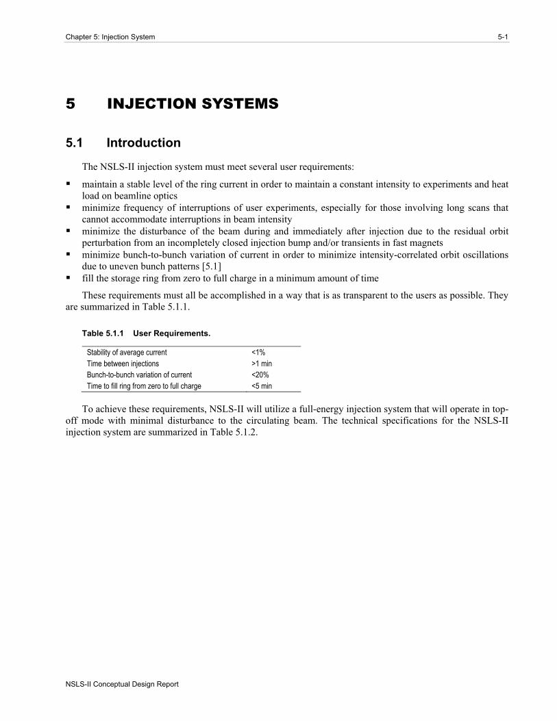
These requirements must all be accomplished in a way that is as transparent to the users as possible. They are summarized in Table 5.1.1.
Table 5.1.1 User Requirements.
Stability of average current <1% Time between injections >1 min Bunch-to-bunch variation of current <20% Time to fill ring from zero to full charge <5 min
To achieve these requirements, NSLS-II will utilize a full-energy injection system that will operate in top-off mode with minimal disturbance to the circulating beam. The technical specifications for the NSLS-II injection system are summarized in Table 5.1.2.

5-2 NSLS-II Conceptual Design Report
Brookhaven National Laboratory
Table 5.1.2 Storage Ring Parameters Related to the NSLS-II Injector.
Parameter Value Energy [GeV] 3.0 Circulating current [A] 0.5 Circumference [m] 780 Revolution period [μs] 2.6 RF frequency [MHz] 499.46 RF wavelength [m] 0.6 Circulating charge [μC] 1.3 Total number of buckets 1300 Number of filled buckets at 80% filling 1040 Charge per bucket [nC] 1.25 Current per bucket [mA] 0.48 Lifetime [min] 180 Interval between top-off cycles [min] 1 Current variation between top-off cycles [%] 0.55 Current variation between top-off cycles [mA] 2.75 Charge variation between top-off cycles [nC] 7.15
As follows from Table 5.1.2, the NSLS-II injection system must supply approximately 7 nC of charge once per minute, assuming a lifetime of 3 hours. For single-bunch injection mode and a moderate repetition rate of a few Hz, replenishing this amount of charge would take a few seconds, occupying a significant fraction of the overall beam time. Therefore, multi-bunch injection is adopted, leading to minimal disturbance for user experiments and lower power consumption by the injection system.
The main ring contains 1,300 RF buckets at 500 MHz. To alleviate the problems of ion trapping in the stored electron beam, approximately 1/5 of the buckets must be left empty. The exact number of buckets to fill is difficult to predict and will be determined empirically during commissioning. Feedback systems and the ultimate vacuum conditions in the ring will determine what requirements will be imposed on the bunch structure. In any case, to keep the current constant with high accuracy, considerable flexibility and accuracy must be built into the bunch transfer timing system, the single-bunch capability, and the current and bunch structure measurement system of the main ring.
5.1.1.1 Injection Sequence The initial fill occurs at the rate of 1 Hz, and nominally 40 bunches are transferred to the main ring
nominally at each injection (this number can be increased to 100 or more bunches) to fill consecutively 1,040 of the 1,300 RF buckets available. Bunch trains from the injector enter the ring in sequence, starting with the front of the ring train and stepping sequentially back in time along the ring train until the end is reached, then skipping over the empty section and starting again at the head of the train, until the required current has been established.
Assuming the same amount of charge per injection (7 nC per bunch train) as for top-off mode, the duration of the initial fill will be about 3 minutes with the injection system running at a 1 Hz repetition rate.
5.1.2 Ring Injection Scope There are several possible basic schemes for the injection system that can meet the requirements stated
above. One is to use a full-energy linear accelerator, which would require no booster synchrotron at all; another is to use a booster synchrotron fed by a small linac.

Chapter 5: Injection System 5-3
NSLS-II Conceptual Design Report
A full-energy linac would provide flexible injection operations and present no technically challenging problems. The disadvantage would be the high cost for the linac and the additional cost of a building to house the linac and transport line. In addition, a full-energy linac is likely to have a lower reliability and higher operations cost than a full-energy booster. A high reliability injection system is especially important for NSLS-II, given its short beam lifetime. For these reasons, a full-energy booster was selected as the NSLS-II injector.
Two approaches were considered for the design of the NSLS-II booster. In the first, a “compact” booster design was developed [5.2] and its cost was estimated. It was shown that a booster of 170 meters circumference, housed in a separate building, could satisfy the requirements for injection into the storage ring. In the second approach, the booster was located in the storage ring tunnel. This results in a much larger circumference for the booster, but most of this is taken up by small stainless steel vacuum pipe. Comparing both approaches revealed a substantially higher total cost for the compact booster due to the extra costs of constructing and shielding a separate building to house it. Therefore, the NSLS-II design employs a booster in the same tunnel and with the same circumference as the storage ring.
The large circumference of the booster (780 m) has the added benefit of simplifying injection and extraction. Due to the long revolution periods (2.5 μsec) of both the booster and the main ring, rise and fall times of the pulsed magnetic components are quite relaxed. It also results in a relaxed booster lattice together with excellent quality of the extracted beam at 3 GeV.
On the other hand, the large booster circumference necessitates keeping the energy of injection into the booster sufficiently high to avoid beam losses at injection, for example, due to gas scattering. The 200 MeV linac is thus specified for injection into the booster.
Two transport lines will be constructed: one to connect the linac to the booster and a second to connect the booster to the main ring. A full set of beam diagnostics will be installed for commissioning and routine operations of the injection system.
In this section we describe all the components of the NSLS-II injection system in the following order: linac and electron gun, linac-to-booster transport line, and booster with booster-to-storage ring transport line.
5.2 Linac
5.2.1 Scope The NSLS-II storage ring requires approximately 7 nC of charge to be delivered in top-off mode once
every minute to replace charge lost through Touschek scattering. This charge should be delivered in a single booster cycle, so that the storage ring beam is disturbed only for the duration of the ring damping time (tens of milliseconds) each minute. Details of this will be presented later in this section. In addition, future storage ring requirements may include single camshaft bunch or timing bunches for user experiments or machine studies. To meet these requirements, two modes of linac operation are envisioned: single-pulse mode with about 1 nC charge per bunch, and multi-bunch mode, where a few tens of bunches of more than 100 pC of charge are delivered.
To have sufficient lifetime in the booster at injection in the presence of gas scattering, an energy of 200 MeV is specified for injection into the booster. To inject bunch trains into a booster with a 500 MHz RF system, a 3 GHz linac bunch structure must fit into the booster buckets of ~1 ns length, separated by 2 ns.
The booster is located in the same tunnel as the storage ring, which results in a large booster circumference. To minimize the booster cost, the aperture of the magnets is kept small. To keep the injection efficiency high given the small magnet aperture, a reasonably small emittance is required. Likewise, a small energy spread is needed to prevent beam loss in the high-dispersion regions of the booster lattice. An

5-4 NSLS-II Conceptual Design Report
Brookhaven National Laboratory
additional requirement is that the linac be able to provide sharp edges to the electron bunch train, to avoid injecting electrons into the ion clearing gap.
Thales and ACCEL have produced turn-key linac systems for Soleil and Diamond, respectively. The Soleil linac, using CERN “LIL” 3.5 m structures, has a smaller energy spread that meets the NSLS-II design specification. An approach similar to the Soleil linac is used as a baseline and described below (Figure 5.2.1). The Diamond injector uses the DESY 5.2 m accelerator structures, resulting in a slightly longer linac. To keep both options open in the preliminary design phase, the linac building has been designed to accommodate either four 5.2 m tanks or five CERN 3.5 m structures.
Figure 5.2.1 Layout of the 200 MeV linear accelerator.
The injector consists of the following subsystems:
100 kV triode gun (e.g., Eimac Y-845) with a 500 MHz modulation at the gun grid and high-voltage deck four shielded lenses, situated between the gun and the buncher a 500 MHz subharmonic pre-bunching cavity with ± 25 kV modulation a 3 GHz pre-bunching cavity with ± 10 kV modulation (100 W power) a 3 GHz stationary wave buncher surrounded by two shielded coils (1.2 m long, 5.5 MW, energy gain of
15 MeV) five traveling wave-accelerating structures at 3 GHz in the 2π/3 mode and with a length of 3.5 m (flange
to flange) a Glazer lens between the buncher and the first accelerating structure two focusing doublets three Klystrons (TH2100, 35 MW) and their modulators. low-level RF controls
5.2.2 Physics Design and Parameters Although a range of parameters will meet the requirements, we focus here on a specific case of
approximately 200 pC per bunch in bunch trains of 40 bunches, to provide details on the injector design. Allowing for faster initial fills and for losses in the injection process, a sufficient margin will be considered at the detailed linac design stage.

Chapter 5: Injection System 5-5
NSLS-II Conceptual Design Report
The energy spread must be controlled throughout the acceleration process. The maximum horizontal size of the beam injected into the booster (Section 5.5) is dominated by the energy spread. For ε = 100 nm-rad (2σ emittance) and maximum βx = 25 m, the zero-dispersion beam size is 1.6 mm. At the maximum dispersion, η = 0.75, and energy spread, ΔE/E = 0.5%, the contribution to beam size is Δσx ≈ ηΔE/E ≈ 3.75 mm.
Recent experience at SOLEIL [5.3] has shown that industry can produce turn-key linac systems that meet these specifications. Because the approach taken may differ significantly from one machine to the next, only the salient points of a generic linac are presented.
A planar triode electron gun, the EIMAC Y845 [5.4], is used with a fast-pulser cathode driver. In single-bunch mode, the cathode is pulsed to create ~1 ns pulses of ~0.5 nC. The DC gun inherently has small energy spread. However, to compress the gun pulse for acceleration in the 2.998 GHz linac and capture it in the 500 MHz booster RF, we need to prevent nonlinearities in the RF from increasing the energy spread beyond the 0.5% (RMS) requirement. This translates into a requirement on the length of the micro-bunches exiting the linac to be less than 11 ps.
To create these short bunches, a bunching system is required. First, a 500 MHz subharmonic buncher is used to compress the charge into bunch lengths less than 1 ns to match the 500 MHz booster bucket. This is followed by a 2.988 GHz pre-buncher that micro-bunches the 1.5 ns bunch train to ≤ 11 ps bunches within the linac buckets. A final buncher simultaneously accelerates the electrons to 3 MeV to increase capture efficiency. In bunch-train mode, the cathode is pulsed on for the duration of the train, up to 200 ns, and is bunched in the process described above. During the preliminary design phase, system performance will be confirmed by E-Gun [5.5] and Parmela [5.6] simulations, and cathode driver experiments at the NSLS electron gun test stand.
The main accelerator is comprised of 3 GHz traveling wave structures, with an energy gain of:
[ ] 12.5 [ ]E MeV P MW=
(5.2-1)
The accelerating structures being considered obtain 52 MeV per tank for an input power of 17.5 MW. Using readily available 35 MW klystrons, the first klystron is power split, with about 5.5 MW feeding the 3 GHz pre-buncher and buncher. The latter has an energy gain of more than 15 MeV. The remaining power feeds the first linac structure. Individual waveguide phase shifters and attenuators are used for adjusting amplitude and phase between elements.
The remaining four tanks are powered by two klystrons for an energy gain of an additional 52 MeV each. Thus, a total of 255 MeV energy gain is possible. For redundancy, two waveguide switches can connect the second klystron to power the two bunchers and first tank. In this scheme, an energy of 170 MeV can be achieved if one klystron fails. This will be explored in the preliminary design phase.
The bunch charge and train current—although not beyond that which has been achieved in other applications [5.3, 5.7]—is sufficient to warrant close attention to beam-loading issues. For traveling wave tanks, the voltage induced along the bunch train on short time scales (compared to the fill time of the cavity) is given by:
1
0 [(1 )(1 ) ]x xbV ir L e xeτ ττ − − −= − − − +
(5.2-2)
where r0 is the shunt impedance, τ the attenuation constant in nepers, L the length of the tank, and x the ratio t/tf, where t is the time duration of the macro-pulse and tf the fill time of the structure.
For forty 200 pC bunches separated by 2 ns (100 mA), this corresponds to about 2% in the correlated energy spread along the bunch train. There are several methods of reducing this beam loading. For a given beam current, the beam loading compensation can be achieved by sending the beam during the filling time of

5-6 NSLS-II Conceptual Design Report
Brookhaven National Laboratory
the second structure. This approach has been successfully implemented at SOLEIL [5.7] for a 300 ns long train current of 9 nC. Alternatively, the effect of beam loading can be diminished by lengthening the macro-pulse, either by simply lengthening the pulse and proportionally reducing the charge per bunch, or by pulsing the gun once every fourth, sixth, or eighth 500 MHz bucket with constant charge per bunch to reduce the effect by the corresponding factor. For example, by filling every sixth ring bucket (12 ns bunch separation), the average current is 21mA and the energy spread due to beam loading drops to 0.4%. This last method may require a sophisticated cathode modulation system, which has not yet been developed.
5.2.3 Klystron Modulators and Power Supplies Pulsed 3 GHz high-power klystrons are a mature technology and several manufacturers can meet or
exceed the 35 MW power requirement. The klystrons are powered by pulsed modulators. The traditional approach is to use Pulse Forming Networks with hard-tube (thyratron) switches to produce RF pulses between 2 and 4 microseconds long. NSLS has recently designed and built such a modulator for the 45 MW tube installed at its DUVFEL facility. Our own experience and studies of reliability at SLAC/PEP-II and Pohang Light Source have shown that the Mean Time Between Failure and Mean Time To Repair of the PFN/hard tube modulator dominate the linac downtime, with rates three times those of the klystron tube and its filament/core bias power supplies [5.8, 5.9]. For this reason, solid-state modulators are being explored for NSLS-II. Several competing designs have been developed for both medical linacs and the X-band International Linear Collider. One such example is the design by Scandi-nova [5.10], which uses a multi-turn primary pulse transformer, reducing the modulator voltage from about 40 kV to 3 kV, further increasing reliability by limiting the high voltage to only the pulse transformer and klystron cathode assembly in the oil tank [5.11]. These systems are also between one-half and one-third the size of similar PFN-type modulators. The decision to use a solid state or a PFN-hard tube modulator will be made during the preliminary design phase.
The 500 MHz subharmonic pre-buncher requires about 6 kW (for a shunt impedance of 250 kΩ) to reach 36 kV. This is well within the range of solid-state RF amplifiers.
The 3 GHz pre-buncher is a single cell with ±10 kV modulation, requiring only 100 W of RF power.
The 3 GHz final buncher is a standing wave structure, requiring 5.5 MW of RF power, and delivering an energy gain of 15 MeV.
The low-level RF can be a duplicate of the DUVFEL RF system [5.12], with a master clock in common with the booster and storage rings driving a 2.988 GHz DRO-based synthesizer whose output is split and feeds direct I/Q modulators for the amplitude and phase control of the individual klystrons. The 500 MHz will be derived from the booster RF that is synthesized in a similar way. Complimentary I/Q demodulators can be used to down-convert to baseband and close amplitude and phase loops around the cavity fields.
5.3 Beam Transport to Booster
This section describes the transport line from the injector linac to the booster. This transport line contains a complete set of diagnostics required for commissioning, operation, and maintenance of the linac.
5.3.1 Structure of the Linac-to-Booster Transfer Line The linac is located on the same level as the booster. In the next phase of design we will determine
whether the linac is installed on floor supports or suspended from the ceiling.
The transfer line from the linac to the booster is shown schematically in Figure 5.3.1. The first bending magnet deflects the electron beam toward the booster and will be used as an energy spectrometer. When the

Chapter 5: Injection System 5-7
NSLS-II Conceptual Design Report
magnet is switched off, the electron beam does not enter the ring tunnel. This design allows early commissioning of the linac, while the assembly of the booster and ring is ongoing. Twiss parameters in the transport line are matched to those in the booster injection point.
fromlinac BQ
BQ
kicker
QD
1
QD
2
QD
3
QD
4QF1
QF2
QF3
QF4
B1
trim
s
trim
s
trim
s
B2
trim
fromlinac BQ
BQ
kicker
QD
1
QD
2
QD
3
QD
4QF1
QF2
QF3
QF4
B1
trim
s
trim
s
trim
s
B2
trim
Figure 5.3.1 Layout of the linac-to-booster transfer line.
The machine functions of the transfer line are shown in Figure 5.3.2. Four pairs of correctors provide adjustment of the electron trajectory in the transport line and proper aiming of the injected beam. The main parameters of the magnetic elements are listed in Table 5.3.1. The injection kicker is installed just before the booster quadrupole in the injection straight. The kicker is of the same design as that used in the storage ring.
Figure 5.3.2 Beta and dispersion functions of the linac-to-booster transport line.
Table 5.3.1 Magnet Characteristics.
Dipole Quadrupole Kicker Corrector Number required 2 8 1 4 Field strength at 200 MeV 0.8 T max 3 T/m max 0.2 T Effective length [m] 0.5 0.2 0.5 0.2 Gap height or diameter [mm] 50 50 50 50
5-8 NSLS-II Conceptual Design Report
Brookhaven National Laboratory
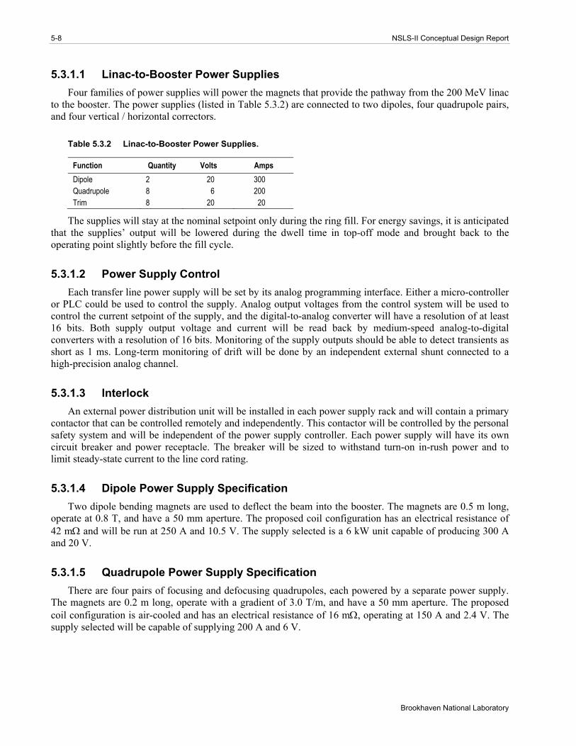
5.3.1.1 Linac-to-Booster Power Supplies Four families of power supplies will power the magnets that provide the pathway from the 200 MeV linac
to the booster. The power supplies (listed in Table 5.3.2) are connected to two dipoles, four quadrupole pairs, and four vertical / horizontal correctors.
Table 5.3.2 Linac-to-Booster Power Supplies.
Function Quantity Volts Amps Dipole 2 20 300 Quadrupole 8 6 200 Trim 8 20 20
The supplies will stay at the nominal setpoint only during the ring fill. For energy savings, it is anticipated that the supplies’ output will be lowered during the dwell time in top-off mode and brought back to the operating point slightly before the fill cycle.
5.3.1.2 Power Supply Control Each transfer line power supply will be set by its analog programming interface. Either a micro-controller
or PLC could be used to control the supply. Analog output voltages from the control system will be used to control the current setpoint of the supply, and the digital-to-analog converter will have a resolution of at least 16 bits. Both supply output voltage and current will be read back by medium-speed analog-to-digital converters with a resolution of 16 bits. Monitoring of the supply outputs should be able to detect transients as short as 1 ms. Long-term monitoring of drift will be done by an independent external shunt connected to a high-precision analog channel.
5.3.1.3 Interlock An external power distribution unit will be installed in each power supply rack and will contain a primary
contactor that can be controlled remotely and independently. This contactor will be controlled by the personal safety system and will be independent of the power supply controller. Each power supply will have its own circuit breaker and power receptacle. The breaker will be sized to withstand turn-on in-rush power and to limit steady-state current to the line cord rating.
5.3.1.4 Dipole Power Supply Specification Two dipole bending magnets are used to deflect the beam into the booster. The magnets are 0.5 m long,
operate at 0.8 T, and have a 50 mm aperture. The proposed coil configuration has an electrical resistance of 42 mΩ and will be run at 250 A and 10.5 V. The supply selected is a 6 kW unit capable of producing 300 A and 20 V.
5.3.1.5 Quadrupole Power Supply Specification There are four pairs of focusing and defocusing quadrupoles, each powered by a separate power supply.
The magnets are 0.2 m long, operate with a gradient of 3.0 T/m, and have a 50 mm aperture. The proposed coil configuration is air-cooled and has an electrical resistance of 16 mΩ, operating at 150 A and 2.4 V. The supply selected will be capable of supplying 200 A and 6 V.
Chapter 5: Injection System 5-9
NSLS-II Conceptual Design Report
5.3.1.6 Corrector Power Supply Specification Each of the four corrector magnets has separate horizontal and vertical coils, powered by separate
supplies. The magnets are 20 cm long and have a resistance of 50 mΩ and inductance of 13 mH. Each magnet is connected to its supply with #10 AWG wire and is expected to be within 100 feet of the load for a lead resistance of less than 20.4 mΩ. The magnets will be powered by linear bipolar power supplies capable of supplying 20 A and 20 V.
5.3.1.7 Kicker Power Supply Specifications A high-voltage power supply designed to operate in constant current mode will charge the HV capacitors
of pulse-forming networks. Injection kicker specifications are described in more detail in Sections 5.9 and 5.10.2.
5.4 Diagnostics/Instrumentation for Linac
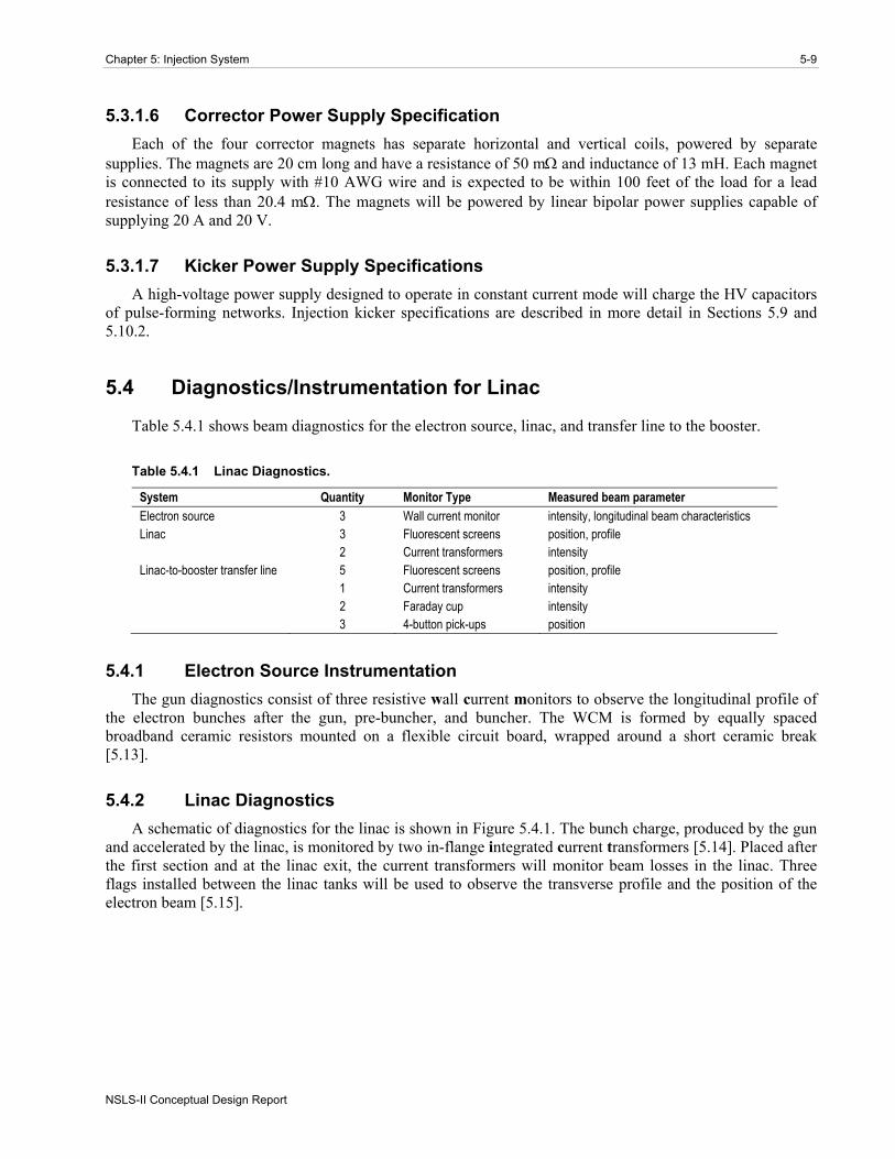
Table 5.4.1 shows beam diagnostics for the electron source, linac, and transfer line to the booster.
Table 5.4.1 Linac Diagnostics.
System Quantity Monitor Type Measured beam parameter Electron source 3 Wall current monitor intensity, longitudinal beam characteristics Linac 3 Fluorescent screens position, profile 2 Current transformers intensity Linac-to-booster transfer line 5 Fluorescent screens position, profile 1 Current transformers intensity 2 Faraday cup intensity 3 4-button pick-ups position
5.4.1 Electron Source Instrumentation The gun diagnostics consist of three resistive wall current monitors to observe the longitudinal profile of
the electron bunches after the gun, pre-buncher, and buncher. The WCM is formed by equally spaced broadband ceramic resistors mounted on a flexible circuit board, wrapped around a short ceramic break [5.13].
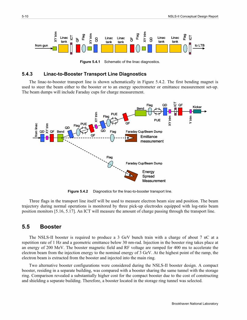
5.4.2 Linac Diagnostics A schematic of diagnostics for the linac is shown in Figure 5.4.1. The bunch charge, produced by the gun
and accelerated by the linac, is monitored by two in-flange integrated current transformers [5.14]. Placed after the first section and at the linac exit, the current transformers will monitor beam losses in the linac. Three flags installed between the linac tanks will be used to observe the transverse profile and the position of the electron beam [5.15].
5-10 NSLS-II Conceptual Design Report
Brookhaven National Laboratory
Linactank
Linactank
Flag Linac
tank
Flag
ICT
XY
trim
QF
QDLinac
tank
Flag
QF
QDIC
T
from gun
XY
trim
XY
trim
to LTB
Linactank
Linactank
Linactank
Flag Linac
tank
Flag
ICT
XY
trim
QF
QDLinac
tank
Flag
QF
QDIC
T
from gun
XY
trim
XY
trim
to LTB
Linactank
Figure 5.4.1 Schematic of the linac diagnostics.
5.4.3 Linac-to-Booster Transport Line Diagnostics The linac-to-booster transport line is shown schematically in Figure 5.4.2. The first bending magnet is
used to steer the beam either to the booster or to an energy spectrometer or emittance measurement set-up. The beam dumps will include Faraday cups for charge measurement.
from
lina
c
ICT
PUE
PUE
PUE
Bend
Bend
Flag
Flag
QD QF Flag Faraday Cup/Beam DumpXY
trim
Emittancemeasurement
EnergySpreadMeasurement
Flag
QD QF Kicker
Faraday Cup/Beam Dump
XY
trim
XY
trim
Y tri
m
QF
QF
QDQD
Flag
from
lina
c
ICT
PUE
PUE
PUE
Bend
Bend
Flag
Flag
QD QF Flag Faraday Cup/Beam DumpXY
trim
Emittancemeasurement
EnergySpreadMeasurement
Flag
QD QF Kicker
Faraday Cup/Beam Dump
XY
trim
XY
trim
Y tri
m
QF
QF
QDQD
Flag
Figure 5.4.2 Diagnostics for the linac-to-booster transport line.
Three flags in the transport line itself will be used to measure electron beam size and position. The beam trajectory during normal operations is monitored by three pick-up electrodes equipped with log-ratio beam position monitors [5.16, 5.17]. An ICT will measure the amount of charge passing through the transport line.
5.5 Booster
The NSLS-II booster is required to produce a 3 GeV bunch train with a charge of about 7 nC at a repetition rate of 1 Hz and a geometric emittance below 30 nm-rad. Injection in the booster ring takes place at an energy of 200 MeV. The booster magnetic field and RF voltage are ramped for 400 ms to accelerate the electron beam from the injection energy to the nominal energy of 3 GeV. At the highest point of the ramp, the electron beam is extracted from the booster and injected into the main ring.
Two alternative booster configurations were considered during the NSLS-II booster design. A compact booster, residing in a separate building, was compared with a booster sharing the same tunnel with the storage ring. Comparison revealed a substantially higher cost for the compact booster due to the cost of constructing and shielding a separate building. Therefore, a booster located in the storage ring tunnel was selected.

Chapter 5: Injection System 5-11
NSLS-II Conceptual Design Report
The concept of placing the booster in the same tunnel as the storage ring was suggested and successfully implemented at the Swiss Light Source (SLS) [5.18, 5.19, 5.20]. This layout was subsequently adopted by other facilities, namely CANDLE [5.21] and ALBA [5.22], and is being considered for the Taiwan Light Source [5.23]. The main advantages of such a layout are in the low cost of lattice elements—together with relaxed tolerances for their design and installation, low power consumption, and excellent output beam parameters. The main disadvantages are an inability to service the booster independently from the main ring, and the potential impact of stray fields from the ramping booster magnets on beam orbit in the storage ring. The success of the SLS injector, which has achieved nearly 100 percent injection efficiency, has shown the same-tunnel booster design to be highly reliable and optimal in cost and performance.
Two alternatives were considered for placing the NSLS-II booster with respect to the storage ring. In the SLS case, the booster is positioned on the inner wall of the storage ring tunnel. The main disadvantage of this layout is the extra cost due to increasing the width of the storage ring tunnel to accommodate the booster ring. In addition, the booster-ring transport line blocks the pathway between the two rings on a scale of tens of meters. Also, the requirement that the inner wall be sufficiently rigid and stable increases construction costs. Consequently, the NSLS-II booster will be placed 1.5 m above the main ring. This is sufficient to not interfere with the ring subsystems and yet still allow easy access to the booster elements for installation and commissioning.
Putting the booster above the storage ring motivates a special arrangement of the booster magnets to provide accessibility for installing insertion devices. It is important not to place the booster elements above the storage ring straight sections. In turn, this defines the symmetry of the booster lattice to be identical to that of the storage ring. In addition, optimization of the overall system cost requires the number of magnetic elements and power supplies for the booster lattice to be minimal.
The design of the booster provides an effective solution that can meet the requirements of the NSLS-II injector.
5.5.1 Lattice Based on the considerations discussed in the introduction to this chapter, the booster lattice incorporates
60 dipoles, with additional focusing magnets. All booster magnets are arranged to avoid having them above the storage ring straight sections (Figure 5.5.1). A single period consists of only a small number of magnetic elements, similar to that of the existing NSLS booster [5.24].
Figure 5.5.1 Layout of the booster and the ring periods plotted on the same scale (meters).
The lattice is designed with twelve identical cells together with three modified cells containing families of quadrupole correctors. Phase advances per cell are chosen as 74° and 40° for horizontal and vertical planes,
5-12 NSLS-II Conceptual Design Report
Brookhaven National Laboratory
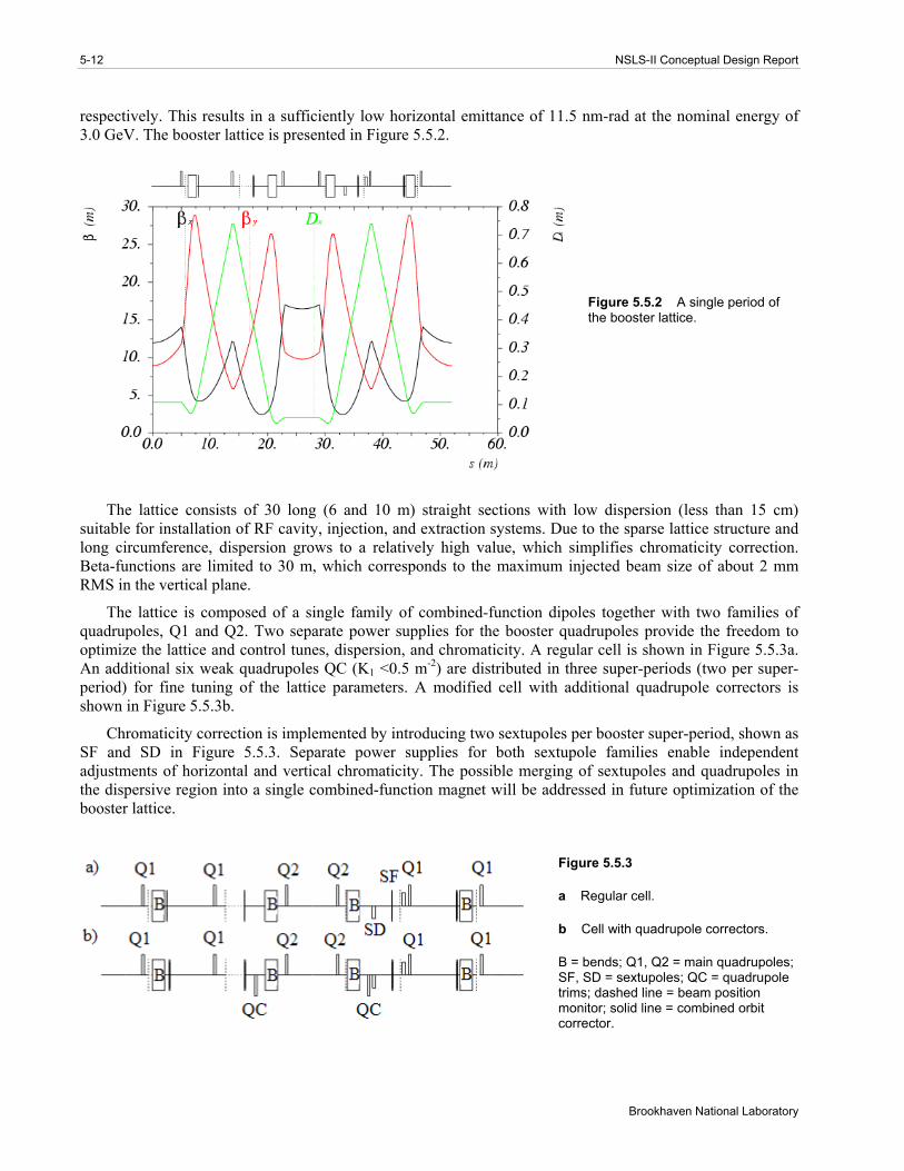
respectively. This results in a sufficiently low horizontal emittance of 11.5 nm-rad at the nominal energy of 3.0 GeV. The booster lattice is presented in Figure 5.5.2.
Figure 5.5.2 A single period of the booster lattice.
The lattice consists of 30 long (6 and 10 m) straight sections with low dispersion (less than 15 cm) suitable for installation of RF cavity, injection, and extraction systems. Due to the sparse lattice structure and long circumference, dispersion grows to a relatively high value, which simplifies chromaticity correction. Beta-functions are limited to 30 m, which corresponds to the maximum injected beam size of about 2 mm RMS in the vertical plane.
The lattice is composed of a single family of combined-function dipoles together with two families of quadrupoles, Q1 and Q2. Two separate power supplies for the booster quadrupoles provide the freedom to optimize the lattice and control tunes, dispersion, and chromaticity. A regular cell is shown in Figure 5.5.3a. An additional six weak quadrupoles QC (K1 <0.5 m-2) are distributed in three super-periods (two per super-period) for fine tuning of the lattice parameters. A modified cell with additional quadrupole correctors is shown in Figure 5.5.3b.
Chromaticity correction is implemented by introducing two sextupoles per booster super-period, shown as SF and SD in Figure 5.5.3. Separate power supplies for both sextupole families enable independent adjustments of horizontal and vertical chromaticity. The possible merging of sextupoles and quadrupoles in the dispersive region into a single combined-function magnet will be addressed in future optimization of the booster lattice.
Figure 5.5.3
a Regular cell.
b Cell with quadrupole correctors.
B = bends; Q1, Q2 = main quadrupoles;SF, SD = sextupoles; QC = quadrupole trims; dashed line = beam position monitor; solid line = combined orbit corrector.
Chapter 5: Injection System 5-13
NSLS-II Conceptual Design Report
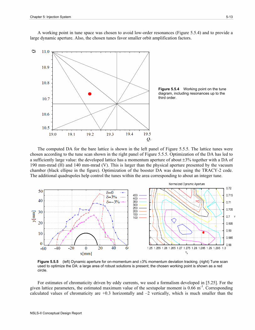
A working point in tune space was chosen to avoid low-order resonances (Figure 5.5.4) and to provide a large dynamic aperture. Also, the chosen tunes favor smaller orbit amplification factors.
Figure 5.5.4 Working point on the tune diagram, including resonances up to the third order.
The computed DA for the bare lattice is shown in the left panel of Figure 5.5.5. The lattice tunes were chosen according to the tune scan shown in the right panel of Figure 5.5.5. Optimization of the DA has led to a sufficiently large value: the developed lattice has a momentum aperture of about ±3% together with a DA of 190 mm-mrad (H) and 140 mm-mrad (V). This is larger than the physical aperture presented by the vacuum chamber (black ellipse in the figure). Optimization of the booster DA was done using the TRACY-2 code. The additional quadrupoles help control the tunes within the area corresponding to about an integer tune.
Figure 5.5.5 (left) Dynamic aperture for on-momentum and ±3% momentum deviation tracking. (right) Tune scan used to optimize the DA: a large area of robust solutions is present; the chosen working point is shown as a red circle.
For estimates of chromaticity driven by eddy currents, we used a formalism developed in [5.25]. For the given lattice parameters, the estimated maximum value of the sextupolar moment is 0.66 m-3. Corresponding calculated values of chromaticity are +0.3 horizontally and –2 vertically, which is much smaller than the

5-14 NSLS-II Conceptual Design Report
Brookhaven National Laboratory
natural chromaticity (–21.7 in both planes) and can be compensated by local modification of the sextupole ramp.
Expected RMS beam sizes along the machine are plotted in Figure 5.5.5. These values correspond to parameters of the beam injected from the linac (εx,y = 100 nm-rad, σγ/γ = 0.5%).
Figure 5.5.6 Injected beam sizes are plotted in mm. Maximum horizontal beam size is determined by dispersion. Dashed lines correspond to the full physical aperture scaled down by a factor of 10.
Note that the maximum horizontal beam size occurs in the quadrupoles Q1, following the behavior of the dispersion function (Figure 5.5.2). Consequently, we increase the size of the vacuum chamber in the dispersive region, providing clearance of about 10 times the RMS size of the injected beam in both planes. Further optimization of the stay-clear aperture will receive attention in our future studies.
The following tolerances for the magnet alignment and fields were assumed (Table 5.5.1). Tolerances on the magnet parameters were developed using analytical estimates that assumed random errors in all magnets. As the table shows, the developed lattice is relaxed with respect to the magnet errors.
Table 5.5.1 Field and Alignment Tolerances for the Booster Magnets.
Parameter Value Quadrupole transverse displacement [mm] 0.15 Dipole transverse displacement [mm] 0.15 Relative bend dipole field error [RMS %] 0.1 Relative bend quadrupole field error (corresponding to 0.05 tune shift) [RMS %] 0.9 Relative quadrupole field error (corresponding to 0.05 tune shift) [RMS %] 1 Dipole roll error [mrad] 2 Quadrupole roll error [mrad] 2
Orbit correction is implemented using 75 beam position monitors and 60 horizontal and 60 vertical trim magnets, producing a maximum deflection angle of 1 mrad. The trim fields will follow the energy ramp, enabling orbit correction at all energies. The developed trim–BPM arrangement allows correcting the booster orbit down to a 0.8 mm maximum deviation in each plane. This requires only 0.2 mrad (RMS) in the corrector strength, making its design simple, with low magnet weight and size. This orbit correction system results in alignment tolerances for the dipoles and quadrupoles of 150 µm in displacement and 2 mrad in roll angle.
Chapter 5: Injection System 5-15
NSLS-II Conceptual Design Report
These tolerances can be relaxed even further, at the expense of slightly larger orbit deviations, by further optimizing the trim arrangement.
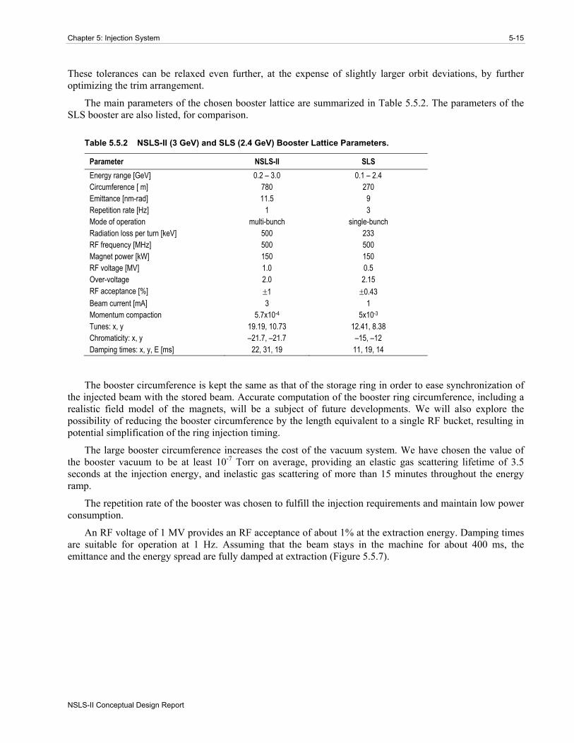
The main parameters of the chosen booster lattice are summarized in Table 5.5.2. The parameters of the SLS booster are also listed, for comparison.
Table 5.5.2 NSLS-II (3 GeV) and SLS (2.4 GeV) Booster Lattice Parameters.
Parameter NSLS-II SLS Energy range [GeV] 0.2 – 3.0 0.1 – 2.4 Circumference [ m] 780 270 Emittance [nm-rad] 11.5 9 Repetition rate [Hz] 1 3 Mode of operation multi-bunch single-bunch Radiation loss per turn [keV] 500 233 RF frequency [MHz] 500 500 Magnet power [kW] 150 150 RF voltage [MV] 1.0 0.5 Over-voltage 2.0 2.15 RF acceptance [%] ±1 ±0.43 Beam current [mA] 3 1 Momentum compaction 5.7x10⁻⁴ 5x10⁻³ Tunes: x, y 19.19, 10.73 12.41, 8.38 Chromaticity: x, y –21.7, –21.7 –15, –12 Damping times: x, y, E [ms] 22, 31, 19 11, 19, 14
The booster circumference is kept the same as that of the storage ring in order to ease synchronization of the injected beam with the stored beam. Accurate computation of the booster ring circumference, including a realistic field model of the magnets, will be a subject of future developments. We will also explore the possibility of reducing the booster circumference by the length equivalent to a single RF bucket, resulting in potential simplification of the ring injection timing.
The large booster circumference increases the cost of the vacuum system. We have chosen the value of the booster vacuum to be at least 10-7 Torr on average, providing an elastic gas scattering lifetime of 3.5 seconds at the injection energy, and inelastic gas scattering of more than 15 minutes throughout the energy ramp.
The repetition rate of the booster was chosen to fulfill the injection requirements and maintain low power consumption.
An RF voltage of 1 MV provides an RF acceptance of about 1% at the extraction energy. Damping times are suitable for operation at 1 Hz. Assuming that the beam stays in the machine for about 400 ms, the emittance and the energy spread are fully damped at extraction (Figure 5.5.7).

5-16 NSLS-II Conceptual Design Report
Brookhaven National Laboratory
Figure 5.5.7 Evolution of horizontal emittance (red, nm-rad) during energy ramp (blue, scaled down by a factor of 100).
Average booster power consumption is only about 75 kW at 1 Hz and is substantially less in top-off mode, when the booster is required to produce a bunch train only once a minute.
5.6 Conceptual Design of Magnets and Hangers
5.6.1 Booster Ring Magnet Design Considerations As at SLS, the NSLS-II booster shares the same tunnel as the storage ring. The large booster
circumference leaves ample space to accommodate magnets of modest field. Unlike SLS, the booster magnets reside directly over the storage ring; this feature is unique to the NSLS-II design. Because of this, water-cooled magnets would present a source of potential leaks above the main ring. These considerations, together with the goal of minimizing system costs, led us to design for operation without water cooling. The following paragraphs present a summary of the work on individual magnetic components that yielded the physics requirements of the present booster lattice configuration. Optimization and refinements in individual components are anticipated during the next phase of preliminary design. Table 5.6.1 lists some basic parameters for the NSLS-II booster magnets.
Table 5.6.1 Booster Magnet Parameters.
Magnet Number of magnets Length, m Strength Dipole 60 (1 family) 1.5 0.7 T, −2.1 T/m*
Quadrupole 60 (1 family) 30 (1 family) 6 (3 families)
0.3 0.3 0.3
9.3 T/m 10 T/m <0.5 T/m
Sextupole 15 (1 family) 15 (1 family)
0.2
0.4 200 T/m2
200 T/m2 Orbit corrector 60 (x and y) 0.2 <1 mrad *Quadrupole gradient in combined-function dipole
The following paragraphs in this section present a partial list of booster magnet design considerations. For the conceptual design these considerations are global in nature and will evolve into more specific parameters during the next phase of preliminary design.
Critical lift and installation safety issues will be of extreme importance because the booster is suspended directly over the storage ring. Handling and rigging safety issues for magnet installation and maintenance

Chapter 5: Injection System 5-17
NSLS-II Conceptual Design Report
personnel will be addressed and the reference design will be in compliance with the laboratory’s critical lift policy.
Electrical and all other safety issues will be addressed during preliminary design. The designs of the magnet, magnet power cable connections, and magnet instrumentation and controls will all comply fully with the requirements of the Nationally Recognized Test Laboratory.
The average current density in the coil section of the booster ring magnets was selected to be less than or equal to 2.5 A/mm2. Electrical, magnetic, and mechanical design optimization will be performed for the reference design of the 1 Hz, H-type combined function dipole, quadrupole, and sextupole magnets to assess the impact of tunnel temperature on the operation of these magnets and to assure that the air-cooled magnets will function reliably with no chance for thermal runaway.
The NSLS-II booster dipole is a combined-function magnet with quadrupole field component introduced by the shape of the poles. This requirement will affect the sequence of dipole magnet fabrication and installation in the tunnel.
Booster ring magnet reference designs will be developed to minimize fabrication costs, provide high operational reliability, and minimize the power consumption of individual components as well as the overall magnet systems.
To assure precise alignment and field quality of the lattice components, it is necessary to develop reference magnet designs and stable mechanical assemblies. These will be integrated into a standardized, stable, low-vibration kinematic support system that can be safely installed and easily surveyed while suspended from the ceiling of the NSLS-II tunnel.
3D magnetic modeling will be performed to determine what level of impact, if any, ramping of the NSLS-II booster ring may have on beam orbit in the storage ring. The results of this modeling study will be appropriately incorporated into the reference designs for the storage ring and booster ring magnets.
Vacuum chambers will be incorporated into each booster magnet to facilitate modular component installation and enhance the safety and simplicity of magnet installation. Orbit correctors can be assembled around the vacuum chamber and simply secured to the ceiling of the tunnel.
These design concepts and considerations will be refined during the next phase of preliminary engineering design, and engineering prototypes of the reference magnets will be produced and evaluated. The final design will ultimately be implemented by the magnet manufacturer and approved by NSLS-II project staff.
5.6.1.1 Conceptual Design of the Booster Dipole Magnet
5.6.1.1.1 Dipole Magnetic Design Parameters The NSLS-II booster ring will be equipped with 60 dipole magnets 1.5 m long with 0.7 T field in the
nominal gap of ~25 mm, for an electron energy of 3.0 GeV. The dipole magnets are H-type, with a curved laminated yoke. The nominal radius of orbit curvature in the bending magnets is 14.56 m; the electron beam is bent by 6.0 degrees with a beam sagitta of 19 mm. The booster dipoles are combined-function magnets with a quadrupole component permanently superimposed in the dipole field by the pole face geometry. Therefore, the magnet must be curved to match the beam orbit, so that the beam is always on the axis of the quadrupole component. The coil was designed by considering the number of turns, the height of the pole gap, and the specifications of the power supply.
Calculations of the magnetic field were made to optimize the pole contours and the quality of the magnetic field. Due to the low-duty cycle for energy ramping, air-cooled coils may be used with a current density of less than 2.5 A/mm² in the copper conductor. This choice will reduce utility costs and improve the

5-18 NSLS-II Conceptual Design Report
Brookhaven National Laboratory
overall reliability of the NSLS-II magnet system. The magnet yokes are made of AISI 1006 low-carbon steel sheet, 1.5 mm thick. The magnet parameters are listed in Table 5.6.2.
Table 5.6.2 Booster Dipole Parameters.
Dipole length [m] 1.5 Radius of curvature [m] 14.58 Nominal gap [mm] 25 Pole width [mm] 60 Dipole field [T] (injection–extraction) 0.046–0.698 Quadrupole gradient [T/m] –2.112 Dipole resistance [mΩ] 15 Dipole inductance [mH] 12 Dipole PS peak current [A] 355 Number of turns per pole 20 Square conductor size [mm] 12.7 Tolerances On magnetic length, for Δφ = 0.1 mrad [mm] 1.4 On gradient, for dQx,y = 0.05 [%] 0.9 On x-position, for Δφ = 0.1 mrad [mm] 0.3
To test the feasibility of the booster dipole design, magnetic modeling was performed. Figure 5.6.1 illustrates a 2D magnetic model of the dipole cross-section with the B-field flux shown in light blue lines. The developed design satisfies the specifications listed in Table 5.6.2 within an acceptable margin.
Figure 5.6.1 Dipole magnetic model.

Chapter 5: Injection System 5-19
NSLS-II Conceptual Design Report
5.6.1.1.2 Mechanical Design of the Booster Dipole Magnet The dipole laminations are keyed and welded together to form two rigid yoke halves. Bracket yoke
clamps are attached to the keys near the parting surface. The mechanical assembly is shown in Figure 5.6.2.
The excitation coils consist of solid copper conductors, 12.7×12.7 mm. The conductor is insulated using layers of fiberglass with a minimum thickness of 0.6 mm around each conductor to form a minimum of 1.2 mm turn-to-turn insulation. An additional 2.0 mm of fiberglass around the outside of the coil forms the ground plane insulation. The coil will be vacuum impregnated with radiation-resistant epoxy resin. The coils will be high-potted up to 5 kV to detect defects in the inter-turn and ground plane insulation of the coil. The coils are installed into the yoke halves and then the yoke halves are keyed and bolted together around a section of booster vacuum chamber. Magnet hanger brackets are attached to the top yoke block in preparation for installation.
Figure 5.6.2 Cross-section of the booster dipole magnet. Note the magnet yoke clamping method.
5.6.1.2 Conceptual Design of the Booster Quadrupole Magnet
5.6.1.2.1 Quadrupole Magnetic Design Parameters The NSLS-II booster will be equipped with 96 quadrupole magnets energized in three families of power
supplies. Ninety of the 96 quadrupole magnets are required to yield a gradient of 10 T/m at 3 GeV, with inhomogeneity of the gradient field of less than 0.1% inside the beam tube. The quadrupoles will have an aperture of 35 mm. The field quality is consistent with the specified gradient throughout the required transverse region. The magnetic cores are made of AISI 1006 low-carbon steel sheet, 1.5 mm thick. The parameters of the quadrupole magnets are listed in Table 5.6.3.

5-20 NSLS-II Conceptual Design Report
Brookhaven National Laboratory
Table 5.6.3 Booster Quadrupole Magnet Parameters at 3 GeV.
Quantity 96 Maximum field gradient [T/m] 10 Magnetic length [m] 0.3 Aperture [mm] 35 Peak current [A] 76 Number of turns per pole 16 Square conductor size [mm] 6.3 Gradient: extraction, injection [T/m] 9.3, 0.62 (1 family of 60)
10.0, 0.67 (1 family of 30) (6 individually powered quadrupoles)
To test the feasibility of the booster quadrupole design, magnetic modeling was performed using OPERA-2D. Figure 5.6.3 shows a 2D magnetic model of the quadrupole cross-section with the B-field flux shown in light blue lines. The developed design satisfies the specifications shown in Table 5.6.3 within an acceptable margin.
Figure 5.6.3 NSLS-II booster quadrupole magnet model. B-field flux lines shown in light blue.

Chapter 5: Injection System 5-21
NSLS-II Conceptual Design Report
5.6.1.2.2 Mechanical Design of the Booster Quadrupole Magnets The top and bottom halves of the quadrupoles are pinned and bolted together to form a flux-return yoke.
To install the coil on the quadrupole, the magnet core is divided into four quadrants. A square copper conductor, 6.3×6.3 mm, was selected for winding the excitation coils. Vacuum-impregnated fiberglass with radiation-resistant epoxy more than 1.0 mm thick will provide interstitial conductor insulation. At least 1.5 mm additional vacuum-impregnated epoxy fiberglass will provide ground plane insulation. The coils will be high-potted up to 5 kV to detect defects in the inter-turn and ground plane insulation of the coil.
Fabrication and assembly concepts have been studied, resulting in the conceptual magnet design shown in Figure 5.6.4.
Figure 5.6.4 NSLS-II booster ring quadrupole magnet cross-section.
5.6.1.3 Sextupole Magnets
5.6.1.3.1 Sextupole Magnetic Design Parameters The 30 sextupole magnets are divided in two families of magnets that are 0.4 m and 0.2 m long. The bore
diameter of 35 mm gives a minimum clearance of 2 mm between the vacuum chamber and the adjacent poles. All sextupole magnets are required to yield strength of 200 T/m2 at 3 GeV, with inhomogeneity of the field strength of less than 0.1% inside the beam tube. The maximum current density in the conductor will not exceed 2.5 A/mm2. The laminated magnet yokes are made of AISI 1006 low-carbon sheet steel, 1.5 mm thick. These parameters are shown in Table 5.6.4.
5-22 NSLS-II Conceptual Design Report
Brookhaven National Laboratory
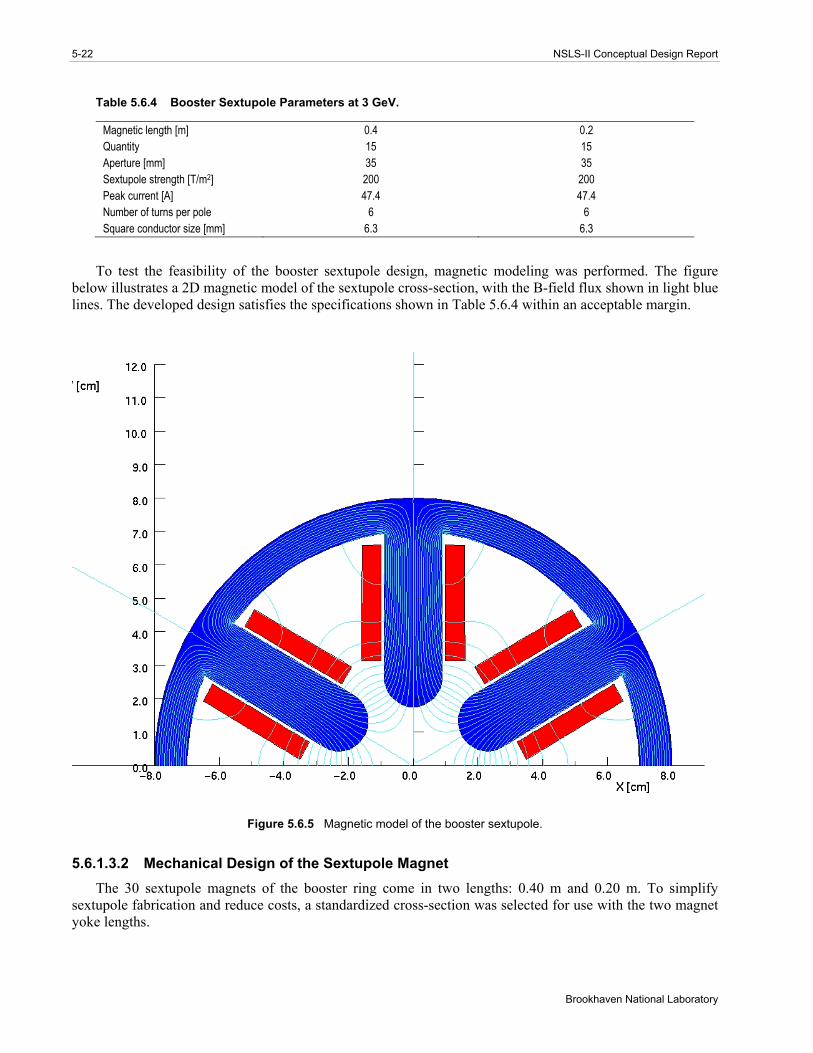
Table 5.6.4 Booster Sextupole Parameters at 3 GeV.
Magnetic length [m] 0.4 0.2 Quantity 15 15 Aperture [mm] 35 35 Sextupole strength [T/m2] 200 200 Peak current [A] 47.4 47.4 Number of turns per pole 6 6 Square conductor size [mm] 6.3 6.3
To test the feasibility of the booster sextupole design, magnetic modeling was performed. The figure below illustrates a 2D magnetic model of the sextupole cross-section, with the B-field flux shown in light blue lines. The developed design satisfies the specifications shown in Table 5.6.4 within an acceptable margin.
Figure 5.6.5 Magnetic model of the booster sextupole.
5.6.1.3.2 Mechanical Design of the Sextupole Magnet The 30 sextupole magnets of the booster ring come in two lengths: 0.40 m and 0.20 m. To simplify
sextupole fabrication and reduce costs, a standardized cross-section was selected for use with the two magnet yoke lengths.

Chapter 5: Injection System 5-23
NSLS-II Conceptual Design Report
The magnet yoke is composed of laminated, AISI 1006 low-carbon sheet steel, 1.5 mm thick. The laminated iron yoke is pinned and welded to form identical sextuplets. A square copper conductor 6.3×6.3 mm was selected for winding the excitation coils. The conductor is wrapped with fiberglass to provide a minimum of 1.0 mm turn-to-turn insulation. An additional 1.5 mm of fiberglass is wrapped around the windings to form the ground plane insulation. The coils are then vacuum impregnated with radiation-resistant epoxy resin. The coils will be high-potted up to 5 kV to detect defects in the inter-turn and ground plane insulation. To assemble the magnet, each sextupole coil will be secured to a sextuplet. The coil and sextuplet assembly are then keyed and bolted together around a flanged length of booster vacuum chamber to form the flux-return yoke. A 2 mm (minimum) clearance between the vacuum chamber and the adjacent poles is maintained to provide thermal insulation during chamber baking and to prevent the transmission of vibrations from the vacuum chamber to the magnet.
Studies of fabrication and assembly concepts have resulted in the design that is shown in Figure 5.6.6. This design will be refined during the next phase of the project.
Figure 5.6.6 NSLS-II booster ring sextupole magnet cross-section.
5.6.1.4 Booster Corrector Magnets The NSLS-II booster will be equipped with 60 combined vertical and horizontal corrector magnets. The
field strength of the corrector magnet is selected to deliver about 1.0 mrad of steering to the electron beam at 3 GeV. In the booster, a conventional window-frame style corrector will be assembled around the beam tube. The corrector yoke will be made of 0.5 mm thick steel sheet. The correctors will follow the ramping excitations of the other magnetic components of the booster. The maximum booster corrector excitation current will be 15 A. The booster corrector magnets will be powered by separate bipolar power supplies.
5.6.2 Booster Magnet Installation The NSLS-II booster presents a number of challenges for tunnel installation, survey, vibration and
magnetic isolation, and servicing. We plan to finish installing portions of the booster lattice before the start of storage ring installation, so that booster commissioning may begin in parallel with storage ring installation. Booster commissioning will occur during the evening shift, while the storage ring is installed during the day.
In contrast to the storage ring, the sparse density of the booster magnets makes the concept of girder support uneconomical. Instead, sections of Unistrut U-channel will be cast into sections of the tunnel roof.

5-24 NSLS-II Conceptual Design Report
Brookhaven National Laboratory
Strut assemblies will be secured to the Unistrut tracks. Most of the individual magnets will be mounted to the ceiling using methods depicted in Figure 5.6.7.
Figure 5.6.7 The 2D CAD cross-sections of the magnet hanger system for the booster magnets. This view shows a quadrupole (left) and dipole (right) magnet mounted to the tunnel ceiling.
This system can be used to provide rigid mounting of individual magnets to the tunnel ceiling. This hanger mounting technique is a low-cost version of the strut systems first developed at ALS, where all the magnets and girders are rigidly mounted using struts. There is ample experience at BNL in the use of ceiling-mounted accelerator systems.
The hanger system shown in Figure 5.6.8 provides a cost-effective and rigid yet versatile solution for mounting and surveying magnetic components.
Figure 5.6.8 Field isolation plate secured beneath the dipole magnet. Note that the laser tracker survey targets are magnetically affixed in the fiducial cups that are secured to the aisle side of the magnet. These targets will be reused and will allow all the booster magnets to be surveyed from below using laser trackers in the tunnel aisle.

Chapter 5: Injection System 5-25
NSLS-II Conceptual Design Report
The plate mounted beneath the assembly magnetically isolates the storage ring components from the ramping booster elements. Magnetic modeling to determine the effectiveness of the isolation plates will be conducted. The use of an isolation plate or steel enclosure around the dipole will be evaluated to ensure appropriate ring isolation without distorting the magnetic fields of the booster ring elements.
The magnets will be pre-surveyed and laser tracker target cups will be mounted to the outside of the iron yoke. These will be used to locate the magnet axis relative to the booster lattice axis during installation. Fiducialization of each magnet will be achieved by conventional alignment methods, e.g., by locating and then securing the fiducials relative to the mechanical center of each dipole and multipole.
The installation of the booster magnets must follow strict engineered lifting procedures that are compliant with the BNL Critical Lift Policy. Special equipment will be designed to aid in the installation of the booster lattice components to minimize safety risks. Figure 5.6.9 shows one of several industrially produced lifting devices that are being considered for booster installation and servicing.
Figure 5.6.9 Possible lifting device for booster installation and servicing.
Some transporter models are steered with the aid of a thin sensor-detectable strip adhered to the floor, forming an electronic track that controls side-to-side motion of the transporter to help prevent collisions with the tunnel wall or storage ring lattice components.
One unit that has been considered as a possibility is the Model 71 4500-lb Electric Side-Loader Truck manufactured by the Raymond Corporation. It can shuttle sideways along the 1.8 m wide tunnel aisle carrying a magnet.
Once the booster magnets have been shuttled to their prescribed location, the side-loader will lift them straight up until they clear the top of the main storage ring. The side loader’s vertical mast moves forward, projecting the magnet radically outward to its approximate position. Final positioning is accomplished by a BNL-designed screw-driven scissor lift with 2D translational capabilities, as shown in Figure 5.6.10.

5-26 NSLS-II Conceptual Design Report
Brookhaven National Laboratory
Figure 5.6.10 Procedure of booster magnet installation. Left: The transporter delivering a booster dipole magnet to its point of installation. Right: Platforms may be added to the transporter system to allow access to the booster ring components for ease of installation, survey, and servicing.
No single model side-loading transporter may have all the features that are needed for NSLS-II. Further investigation will address desirable custom options, adaptations, and safety features—such as ergonomics, tunnel egress, critical lift issues, and the incorporation of extendable manned platforms.
5.6.3 Booster Power Supplies The power supplies are designed to ramp from a low current at injection to a higher current at extraction
(Figure 5.6.11). The shortest total ramp time for both up and down ramps is 1 second. The time between ramp cycles can vary from milliseconds to minutes. This longer time between cycles will be used for top-off operations. All power supplies will have at least a 20% operating current margin.
Figure 5.6.11 Dipole power supply current and voltage waveforms for 3.0 GeV operation.

Chapter 5: Injection System 5-27
NSLS-II Conceptual Design Report
All power supplies will be capable of programmable ramping profiles, which will be stored in a Waveform Function Generator All profiles will be synchronized by a global timing system. Figure 5.6.12 shows the block diagram for the dipole power supply.
Figure 5.6.12 Dipole power supply block diagram.

5-28 NSLS-II Conceptual Design Report
Brookhaven National Laboratory
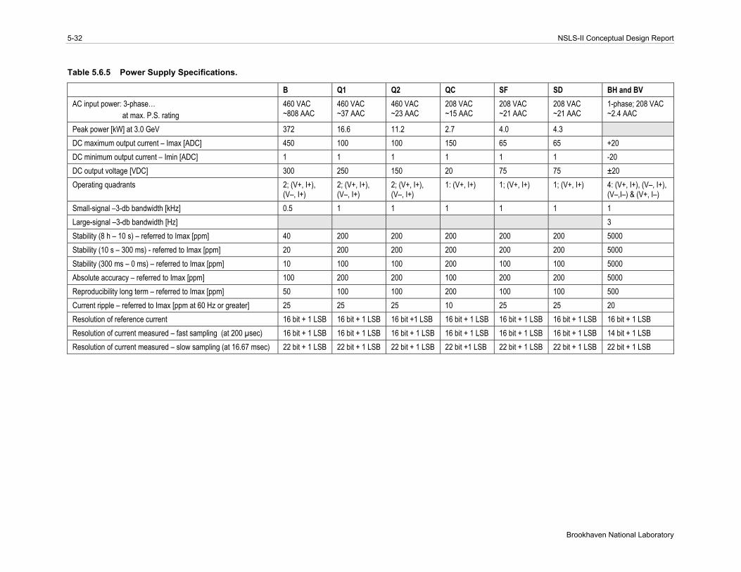
The booster power supplies are listed below and discussed in detail in the rest of this section. The anticipated power consumption of the power supplies is quite low. The booster ring power supplies consume only 150 kW over a 1-second fill cycle. During top-off with a 1-minute cycle between fills, the average power usage is estimated to be 23 kW. Table 5.6.5 lists the specifications for the different power supply families, for comparison.
B-PS – 60 dipole magnets in series circuit Q1-PS – 60 quadrupole magnets in a series circuit Q2-PS – 30 quadrupole magnets in a series circuit QC-PS1 to QC-PS13 – 2 quadrupole magnets in a series circuit, 3 separate circuits SF-PS – 15 sextupole magnets in a series circuit SD-PS – 15 sextupole magnets in a series circuit BH-PS1 to BH-PS60 – 60 horizontal correction dipole circuits BV-PS1 to BV-PS60 – 60 vertical correction dipole circuits
5.6.3.1 B-PS – Main Dipole Power Supply The B-PS circuit consists of 60 dipole magnets, each 15.7 mΩ and 12 mH. The operating current is ~355
A for 3.0 GeV. Cabling between the magnets and the return bus will use 650 MCM flexible copper cable with a resistance of 0.11 Ω and inductance of 1.4 mH. The power supply load is 1.06 Ω and 0.72 H. The B-PS current and voltage waveforms for 3.0 GeV operations can be seen in Figure 5.6.11. The electrical diagram for this power supply is shown in Figure 5.6.12. This power supply is a unipolar, two-quadrant, current-regulated supply. It will use two 12-pulse SCR converters in series, with the center point connected to ground. This configuration will reduce the voltage rating on various converter components. Each converter will have a ripple current to low levels. The power supply will be able to run in the invert mode while ramping down. This produces a negative voltage and recovers the stored energy in the magnets.
A combined digital and analog control system will control the operation of the B-PS power converter. The power supply will have a precision current regulator using a DCCT as the current feedback device. The digital controls will use a feed-forward system to improve the overall reproducibility on the ramp. A PLC will be used for state control (on/off commands and interlocks).
5.6.3.2 Q1-PS and Q2-PS – Quadrupole Power Supplies The Q1 and Q2 circuits will share a power supply. The power supply will be able to run in the invert
mode while ramping down, which produces a negative voltage and recovers the stored energy in the magnets. The Q1 circuit consists of 60 quadrupole magnets, each 21 mΩ and 2.7 mH. Cabling between the magnets and the return bus will use #1 AWG flexible copper cable with a resistance of 0.86 Ω and inductance of 1.4 mH. The Q1 power supply load is 2.12 Ω and 0.16 H.
The Q2 circuit consists of 30 quadrupole magnets, each 21 mΩ and 2.7 mH. Cabling between the magnets and the return bus will use #1 AWG flexible copper cable with a resistance of 0.75 Ω and inductance of 1.4 mH. The Q2 power supply load is 1.38 Ω and 82 mH. The operating current for both circuits is ~76 A for 3.0 GeV.
Q1-PS and Q2-PS are unipolar, two-quadrant, current-regulated supplies. Each power supply will consist of a 12-pulse SCR converter with a single-stage LCRL passive filter and a series pass active filter (see Figure 5.6.13). A combined digital and analog control system will control the operation of the power converter. This power supply will have a precision current regulator using a DCCT as the current feedback device. The digital controls will use a feed-forward system to improve the overall reproducibility. A PLC will be used for state control (on/off commands and interlocks).

Chapter 5: Injection System 5-29
NSLS-II Conceptual Design Report
Figure 5.6.13 Q1 and Q2 quadrupole power supply block diagram.
5.6.3.3 QC-PS – Quadrupole Power Supply There are three QC circuits, each consisting of two quadrupole magnets, each 21 mΩ and 2.7 mH. The
operating current is ~76 A for 3.0 GeV. Cabling between the magnets and the return bus will use #1 AWG flexible copper cable with a resistance of 50 mΩ and inductance of 0.1 mH. The power supply load is 92 mΩ and 5.4 mH. There also are three QC power supply circuits.
QC-PS is a unipolar, single-quadrant, current-regulated, switch-mode power supply. It will use a series pass output stage. An analog control system will control the operation of QC-PS. The power supply will have a precision current regulator using a DCCT as the current feedback device. The digital controls will use a feed-forward system to improve overall reproducibility. A micro-controller or PLC will be used for state control (on/off commands and interlocks).
5.6.3.4 SF-PS and SD-PS – Sextupole Power Supplies The SF and SD circuits will share a power supply. Both circuits consist of 15 sextupole magnets. Each SF
magnet is 7.1 mΩ and 0.54 mH, and each SD magnet is 14.1 mΩ and 1.1 mH. The operating current for both circuits is ~47 A for 3.0 GeV. Each circuit has the same cabling between the magnets and the return: #1 AWG flexible copper cable with a resistance of 0.69 Ω and inductance of 1.0 mH. The power supply load for the SF circuit is 0.8 Ω and 8 mH.
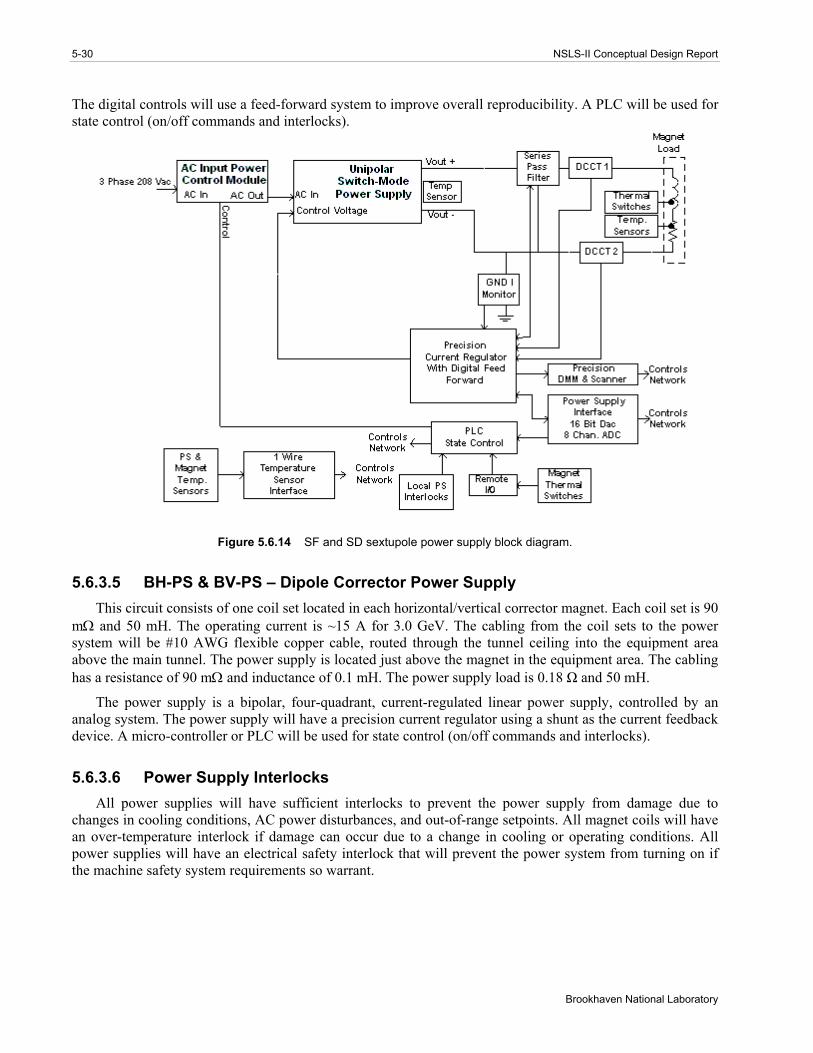
SF- and SD-PS are unipolar, single-quadrant, current-regulated, switch-mode power supplies (Figure 5.6.14). A combined digital and analog control system will control the operation of the power converter. These power supplies will have a precision current regulator using a DCCT as the current feedback device.
5-30 NSLS-II Conceptual Design Report
Brookhaven National Laboratory
The digital controls will use a feed-forward system to improve overall reproducibility. A PLC will be used for state control (on/off commands and interlocks).
Figure 5.6.14 SF and SD sextupole power supply block diagram.
5.6.3.5 BH-PS & BV-PS – Dipole Corrector Power Supply This circuit consists of one coil set located in each horizontal/vertical corrector magnet. Each coil set is 90
mΩ and 50 mH. The operating current is ~15 A for 3.0 GeV. The cabling from the coil sets to the power system will be #10 AWG flexible copper cable, routed through the tunnel ceiling into the equipment area above the main tunnel. The power supply is located just above the magnet in the equipment area. The cabling has a resistance of 90 mΩ and inductance of 0.1 mH. The power supply load is 0.18 Ω and 50 mH.
The power supply is a bipolar, four-quadrant, current-regulated linear power supply, controlled by an analog system. The power supply will have a precision current regulator using a shunt as the current feedback device. A micro-controller or PLC will be used for state control (on/off commands and interlocks).
5.6.3.6 Power Supply Interlocks All power supplies will have sufficient interlocks to prevent the power supply from damage due to
changes in cooling conditions, AC power disturbances, and out-of-range setpoints. All magnet coils will have an over-temperature interlock if damage can occur due to a change in cooling or operating conditions. All power supplies will have an electrical safety interlock that will prevent the power system from turning on if the machine safety system requirements so warrant.
Chapter 5: Injection System 5-31
NSLS-II Conceptual Design Report
5.6.3.7 Electrical Safety All power supplies will conform to the latest BNL safety requirements, especially concerning arc flash
protection. Whenever possible, NRTL-listed equipment will be used.
5.6.3.8 Cable Tray The cable tray for the magnet circuits will be located inside the main tunnel, on the ceiling. All cables will
be tray-rated. Power cables will be arranged to minimize pickup from other circuits. All power cables will be separated from signal cables. All cables and trays will meet NEC requirements.
5.6.3.9 Power Supply Instrumentation Redundant DCCTs or shunts will be used to confirm the power supply current reproducibility. High-
precision DMMs and scanners will be used to monitor the power system current, the redundant current sensor, and the analog current setpoint. This equipment will ensure long-term stability and reproducibility. Temperature monitoring of the magnet coils and power system environment will be accomplished using low-cost digital temperature sensors. With such system, a problem can be identified before it becomes an emergency, making it possible for repairs to be scheduled more conveniently and economically.
5.6.3.10 Power Supply Controls Each booster power supply circuit will require a Waveform Function Generator. These VME device cards
will be located in a control system’s VME chassis, mounted in one of the power supply system racks. The WFGs will generate the reference current profiles, input analog data, and perform digital state control and status readbacks. A timing system will be needed to synchronize all the WFGs. The output of the WFGs is connected via fiber optics to a Power Supply Interface. The PSI has a precision digital-to-analog converter for generating the reference current, and a multi-channel analog-to-digital converter for inputting power system signals. The PSI also has digital IO for state control and status readbacks of the power supply.
The other controls will include the operation of the high-precision DMM and scanner, and readout of the digital temperature sensors.
5-32 NSLS-II Conceptual Design Report
Brookhaven National Laboratory
Table 5.6.5 Power Supply Specifications.
B Q1 Q2 QC SF SD BH and BV AC input power: 3-phase… at max. P.S. rating
460 VAC ~808 AAC
460 VAC ~37 AAC
460 VAC ~23 AAC
208 VAC ~15 AAC
208 VAC ~21 AAC
208 VAC ~21 AAC
1-phase; 208 VAC ~2.4 AAC
Peak power [kW] at 3.0 GeV 372 16.6 11.2 2.7 4.0 4.3 DC maximum output current – Imax [ADC] 450 100 100 150 65 65 +20 DC minimum output current – Imin [ADC] 1 1 1 1 1 1 -20 DC output voltage [VDC] 300 250 150 20 75 75 ±20 Operating quadrants 2; (V+, I+),
(V–, I+) 2; (V+, I+), (V–, I+)
2; (V+, I+), (V–, I+)
1: (V+, I+)
1; (V+, I+)
1; (V+, I+)
4: (V+, I+), (V–, I+), (V–,I–) & (V+, I–)
Small-signal –3-db bandwidth [kHz] 0.5 1 1 1 1 1 1 Large-signal –3-db bandwidth [Hz] 3 Stability (8 h – 10 s) – referred to Imax [ppm] 40 200 200 200 200 200 5000 Stability (10 s – 300 ms) - referred to Imax [ppm] 20 200 200 200 200 200 5000 Stability (300 ms – 0 ms) – referred to Imax [ppm] 10 100 100 200 100 100 5000 Absolute accuracy – referred to Imax [ppm] 100 200 200 100 200 200 5000 Reproducibility long term – referred to Imax [ppm] 50 100 100 200 100 100 500 Current ripple – referred to Imax [ppm at 60 Hz or greater] 25 25 25 10 25 25 20 Resolution of reference current 16 bit + 1 LSB 16 bit + 1 LSB 16 bit +1 LSB 16 bit + 1 LSB 16 bit + 1 LSB 16 bit + 1 LSB 16 bit + 1 LSB Resolution of current measured – fast sampling (at 200 µsec) 16 bit + 1 LSB 16 bit + 1 LSB 16 bit + 1 LSB 16 bit + 1 LSB 16 bit + 1 LSB 16 bit + 1 LSB 14 bit + 1 LSB Resolution of current measured – slow sampling (at 16.67 msec) 22 bit + 1 LSB 22 bit + 1 LSB 22 bit + 1 LSB 22 bit +1 LSB 22 bit + 1 LSB 22 bit + 1 LSB 22 bit + 1 LSB
Chapter 5: Injection System 5-33
NSLS-II Conceptual Design Report
5.7 Beam Chambers and Vacuum System
5.7.1 Scope The booster ring vacuum system provides the acceptable vacuum pressure for the beam within the
vacuum chambers in the booster. The vacuum system includes all vacuum chambers, vacuum pumps, vacuum instrumentation and diagnostics, vacuum controllers, and connecting wiring. The vacuum chamber design, materials, and processes are described in Section 5.7.2. The estimated gas load, pumping scheme, and expected pressure distribution in the booster are given in Section 5.7.3. The vacuum monitoring and control are explained in Section 5.7.4.
An average pressure below 1x10⁻⁷ Torr (see Section 5.5.1) is needed within the booster to minimize the induced beam loss and the resultant ionizing radiation that result from bremsstrahlung scattering. The booster vacuum system will be designed with sufficient pumping capability to achieve vacuum pressures in the 10-8 Torr range. The booster ring vacuum system includes an array of chambers, pumps, diagnostics, and regulation devices placed and selected for optimal performance and low maintenance and long, trouble-free operation. Most of the booster vacuum chambers will be constructed from seamless stainless steel tubing and will utilize Conflat flanges.
5.7.2 Mechanical Design
5.7.2.1 Approach to Booster Vacuum System Design The full-energy booster synchrotron will be located above the storage ring in the same tunnel and
consequently will have the same circumference as the storage ring. This choice will be less costly than a compact booster, due to savings in civil construction cost, even though the cost of the vacuum systems will be higher due to longer beam tube length and many more pumps. The mounting and service of the vacuum systems will also be more challenging.
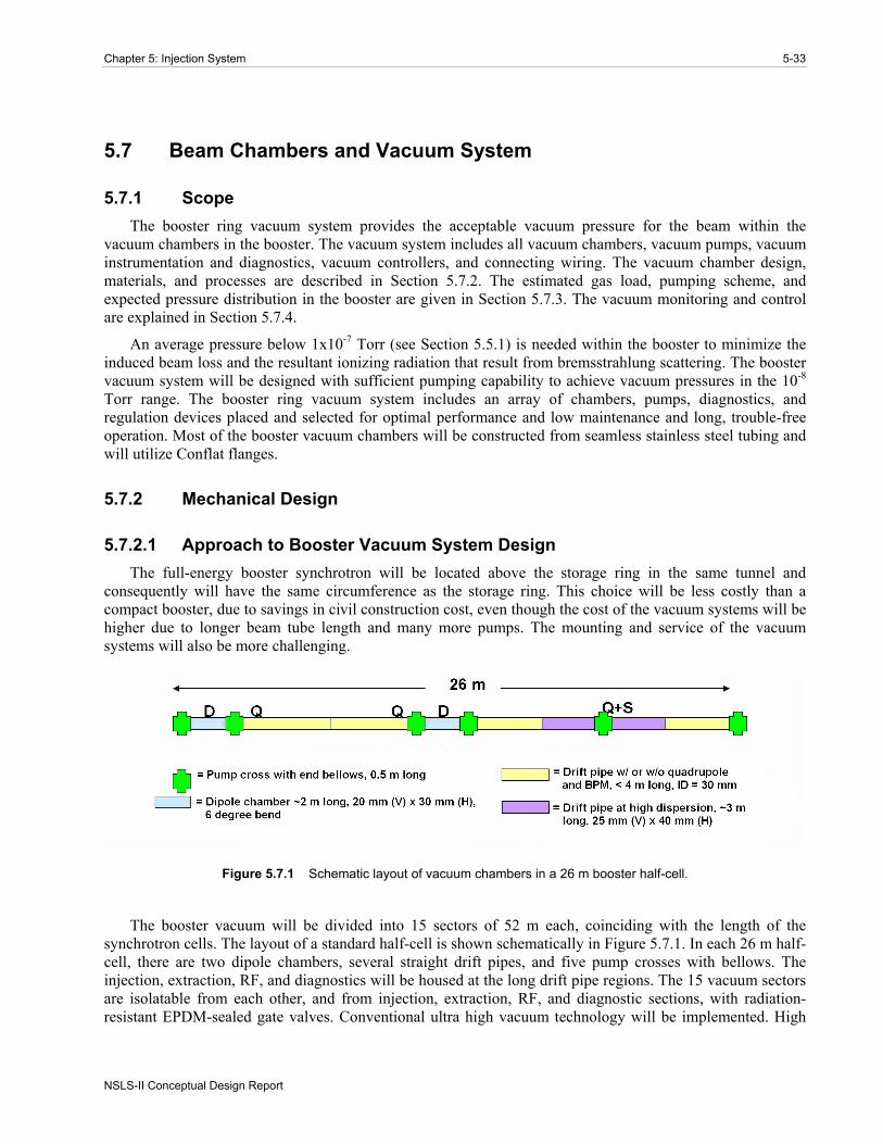
Figure 5.7.1 Schematic layout of vacuum chambers in a 26 m booster half-cell.
The booster vacuum will be divided into 15 sectors of 52 m each, coinciding with the length of the synchrotron cells. The layout of a standard half-cell is shown schematically in Figure 5.7.1. In each 26 m half-cell, there are two dipole chambers, several straight drift pipes, and five pump crosses with bellows. The injection, extraction, RF, and diagnostics will be housed at the long drift pipe regions. The 15 vacuum sectors are isolatable from each other, and from injection, extraction, RF, and diagnostic sections, with radiation-resistant EPDM-sealed gate valves. Conventional ultra high vacuum technology will be implemented. High

5-34 NSLS-II Conceptual Design Report
Brookhaven National Laboratory
vacuum will be achieved with 30 l/s sputter ion pumps distributed around the booster ring. An aluminum foil window at the end of the booster-storage ring transfer line may separate the booster high vacuum from the storage ring ultra high vacuum.
5.7.2.2 Vacuum Chamber Design The booster will accelerate the 200 MeV bunch train from the linac to the full energy of 3 GeV at 1 Hz
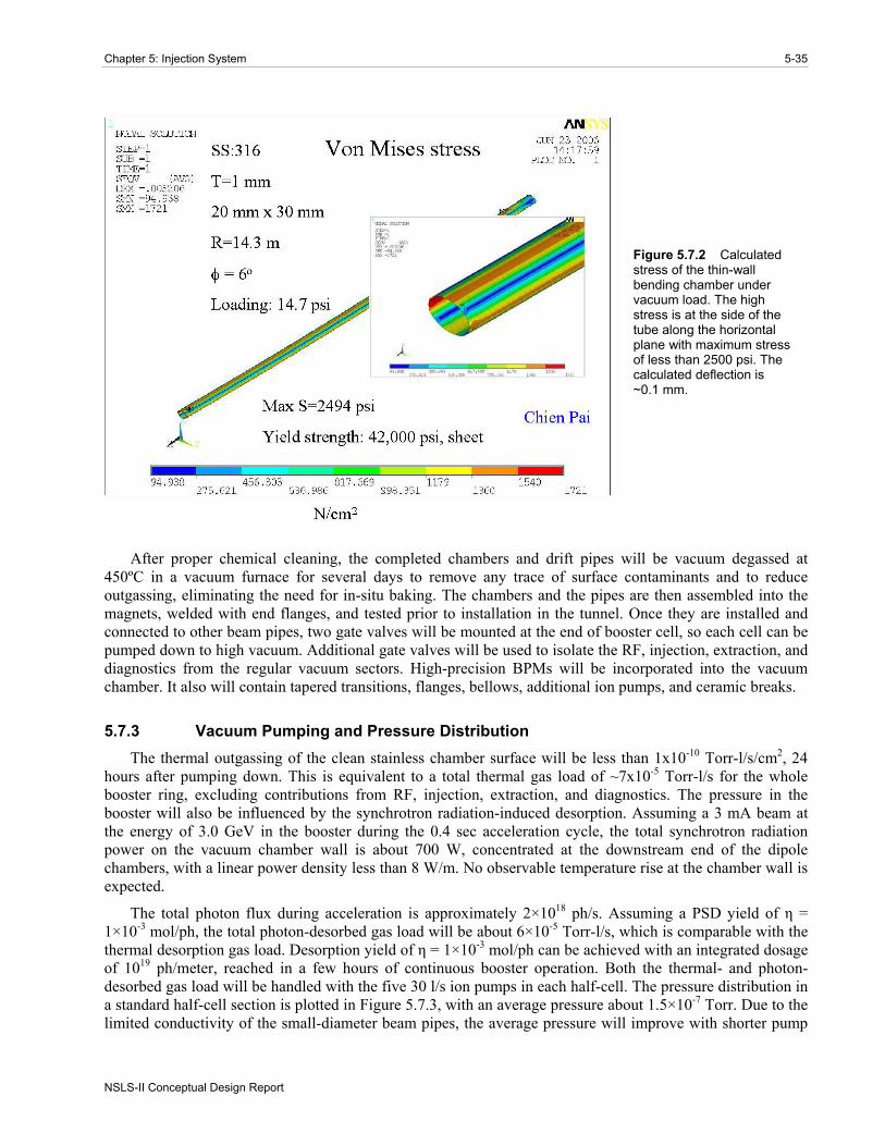
repetition rate. To minimize the eddy currents during the fast ramping fields (and the associated sextupole effect), the vacuum chambers will be made of thin-wall stainless steel. A wall thickness of about 1 mm is sufficiently strong for a dipole chamber with an elliptical cross section of 20 mm (V) × 30 mm (H), while having sufficiently low eddy currents. The 60 dipole chambers will be about 2 m long with a bending radius of 14.3 m. They will be made from seamless tubing, drawn and pushed into elliptical shape, then roll-curved to give the 6 degree bend angle. The ends of the dipole chambers will be tapered from elliptical to round cross-section and welded to Conflat flanges. The maximum stress and deflection of the dipole chamber under the external atmospheric pressure occurs at the top and bottom of the chambers. Using ANSYS analysis, the stress and deflection are found to be 2500 psi and 0.1 mm, respectively (Figure 5.7.2), which is well within acceptable ranges with large safety margins. To reduce eddy currents further, the dipole chambers can be made of Inconel 625 material with thinner walls, which has higher yield strength, lower magnetic permeability, and a resistivity 60% higher than stainless. Inconel 625 can be TIG-welded to the stainless flanges with ease. The additional cost of fabricating the dipole chambers from Inconel is small, since the total length of the dipole chambers is approximately 15% of the overall length.
The straight drift pipes around the high-dispersion quadrupole will also have an elliptical shape to accommodate the required large horizontal aperture. The vacuum chamber size in these regions is 40 mm (V) × 25 mm (H). The balance of the beam pipes will be made of 1 mm wall, 32 mm OD tubes of round stainless steel. To simplify the fabrication, alignment, and mounting of the beam pipes, the BPMs and the quadrupole chamber will be part of the drift pipes. Two drift pipes in each half-cell will have a precision-machined block welded to one end for mounting the BPM buttons. Two pump crosses with bellows will bracket each dipole chamber and there will be one pump cross in the middle of the long drift section. Conflat flanges (size DN38) will be used throughout the booster ring.
Chapter 5: Injection System 5-35
NSLS-II Conceptual Design Report
Figure 5.7.2 Calculated stress of the thin-wall bending chamber under vacuum load. The high stress is at the side of the tube along the horizontal plane with maximum stress of less than 2500 psi. The calculated deflection is ~0.1 mm.
After proper chemical cleaning, the completed chambers and drift pipes will be vacuum degassed at 450ºC in a vacuum furnace for several days to remove any trace of surface contaminants and to reduce outgassing, eliminating the need for in-situ baking. The chambers and the pipes are then assembled into the magnets, welded with end flanges, and tested prior to installation in the tunnel. Once they are installed and connected to other beam pipes, two gate valves will be mounted at the end of booster cell, so each cell can be pumped down to high vacuum. Additional gate valves will be used to isolate the RF, injection, extraction, and diagnostics from the regular vacuum sectors. High-precision BPMs will be incorporated into the vacuum chamber. It also will contain tapered transitions, flanges, bellows, additional ion pumps, and ceramic breaks.
5.7.3 Vacuum Pumping and Pressure Distribution The thermal outgassing of the clean stainless chamber surface will be less than 1x10⁻¹⁰ Torr-l/s/cm2, 24
hours after pumping down. This is equivalent to a total thermal gas load of ~7x10⁻⁵ Torr-l/s for the whole booster ring, excluding contributions from RF, injection, extraction, and diagnostics. The pressure in the booster will also be influenced by the synchrotron radiation-induced desorption. Assuming a 3 mA beam at the energy of 3.0 GeV in the booster during the 0.4 sec acceleration cycle, the total synchrotron radiation power on the vacuum chamber wall is about 700 W, concentrated at the downstream end of the dipole chambers, with a linear power density less than 8 W/m. No observable temperature rise at the chamber wall is expected.
The total photon flux during acceleration is approximately 2×10¹⁸ ph/s. Assuming a PSD yield of η = 1×10⁻³ mol/ph, the total photon-desorbed gas load will be about 6×10⁻⁵ Torr-l/s, which is comparable with the thermal desorption gas load. Desorption yield of η = 1×10⁻³ mol/ph can be achieved with an integrated dosage of 1019 ph/meter, reached in a few hours of continuous booster operation. Both the thermal- and photon-desorbed gas load will be handled with the five 30 l/s ion pumps in each half-cell. The pressure distribution in a standard half-cell section is plotted in Figure 5.7.3, with an average pressure about 1.5×10⁻⁷ Torr. Due to the limited conductivity of the small-diameter beam pipes, the average pressure will improve with shorter pump
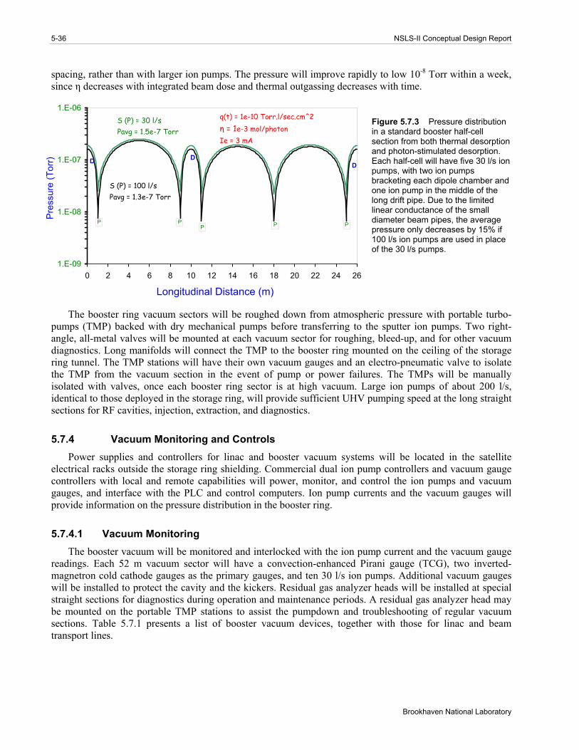
5-36 NSLS-II Conceptual Design Report
Brookhaven National Laboratory
spacing, rather than with larger ion pumps. The pressure will improve rapidly to low 10-8 Torr within a week, since η decreases with integrated beam dose and thermal outgassing decreases with time.
1.E-09
1.E-08
1.E-07
1.E-06
0 2 4 6 8 10 12 14 16 18 20 22 24 26
Longitudinal Distance (m)
Pre
ssur
e (T
orr)
q(t) = 1e-10 Torr.l/sec.cm^2η = 1e-3 mol/photonIe = 3 mA
P
S (P) = 30 l/sPavg = 1.5e-7 Torr
S (P) = 100 l/sPavg = 1.3e-7 Torr
P PP
DDD
P
Figure 5.7.3 Pressure distribution in a standard booster half-cell section from both thermal desorption and photon-stimulated desorption. Each half-cell will have five 30 l/s ion pumps, with two ion pumps bracketing each dipole chamber and one ion pump in the middle of the long drift pipe. Due to the limited linear conductance of the small diameter beam pipes, the average pressure only decreases by 15% if 100 l/s ion pumps are used in place of the 30 l/s pumps.
The booster ring vacuum sectors will be roughed down from atmospheric pressure with portable turbo-pumps (TMP) backed with dry mechanical pumps before transferring to the sputter ion pumps. Two right-angle, all-metal valves will be mounted at each vacuum sector for roughing, bleed-up, and for other vacuum diagnostics. Long manifolds will connect the TMP to the booster ring mounted on the ceiling of the storage ring tunnel. The TMP stations will have their own vacuum gauges and an electro-pneumatic valve to isolate the TMP from the vacuum section in the event of pump or power failures. The TMPs will be manually isolated with valves, once each booster ring sector is at high vacuum. Large ion pumps of about 200 l/s, identical to those deployed in the storage ring, will provide sufficient UHV pumping speed at the long straight sections for RF cavities, injection, extraction, and diagnostics.
5.7.4 Vacuum Monitoring and Controls Power supplies and controllers for linac and booster vacuum systems will be located in the satellite
electrical racks outside the storage ring shielding. Commercial dual ion pump controllers and vacuum gauge controllers with local and remote capabilities will power, monitor, and control the ion pumps and vacuum gauges, and interface with the PLC and control computers. Ion pump currents and the vacuum gauges will provide information on the pressure distribution in the booster ring.
5.7.4.1 Vacuum Monitoring The booster vacuum will be monitored and interlocked with the ion pump current and the vacuum gauge
readings. Each 52 m vacuum sector will have a convection-enhanced Pirani gauge (TCG), two inverted-magnetron cold cathode gauges as the primary gauges, and ten 30 l/s ion pumps. Additional vacuum gauges will be installed to protect the cavity and the kickers. Residual gas analyzer heads will be installed at special straight sections for diagnostics during operation and maintenance periods. A residual gas analyzer head may be mounted on the portable TMP stations to assist the pumpdown and troubleshooting of regular vacuum sections. Table 5.7.1 presents a list of booster vacuum devices, together with those for linac and beam transport lines.

Chapter 5: Injection System 5-37
NSLS-II Conceptual Design Report
Table 5.7.1 List of Vacuum Components for the Linac and Booster Vacuum Systems.
IP (30 l/s) IP (200 l/s) TCG CCG TMP RGA GV E-gun 2 2 2 2 1 1 2 GtL 2 1 2 1 2 Linac 8 4 8 1 1 2 LtB 4 2 4 1 2 Booster 150 8 19 38 8 5 19 BtSR 6 1 2 1 1 2 Total 162 20 29 56 13 8 29
5.7.4.2 Vacuum Controls The vacuum control system will interface with vacuum devices while being part of the machine control.
Due to the high radiation levels in the tunnel, all the vacuum devices will be located at the satellite control racks. These vacuum devices (such as gauge controllers, ion pump controllers, RGA, etc.), with local and remote capabilities, will communicate with the machine control system through RS232 or Ethernet links for remote monitoring, operation, and control. The low-level vacuum control will consist of dedicated vacuum programmable logic controllers. Each PLC has both digital and analog I/O modules with inputs from various vacuum devices, and provides the logic for the operation of the sector gate valves, the interlocks for other subsystem devices, and generation of the beam permits. For the gate valve control, a voting scheme with inputs from the setpoint contacts of several ion pumps will be used to initiate the interlock functions, therefore minimizing false triggering due to the failure of a single pump.
5.8 RF Acceleration System
5.8.1 Introduction The booster RF acceleration system must capture the bunch train injected from the 3 GHz linac,
accelerate it to 3 GeV, and transfer the bunch train to the storage ring RF buckets at 500 MHz (Table 5.8.1).
Table 5.8.1 RF and Beam Parameters for the Booster.
RF frequency [MHz] 500 Loss per turn (3 GeV) [keV] 493 Overvoltage 2 Accelerating voltage [MV] 1 Momentum compaction 5.7x10⁻⁴ Bunch charge [pC] 200 Number of bunches 40 Nominal beam power for top-off [kW] 1.3
The requirement for 1 MV eliminates using a single one-cell cavity at 500 MHz. Rather than using two or more single cells, the five-cell PETRA cavity was chosen [5.26]. The cavity parameters are given in Table 5.8.2. The cavity geometry is shown in Figure 5.8.1.

5-38 NSLS-II Conceptual Design Report
Brookhaven National Laboratory
Table 5.8.2 Parameters for the Five-Cell PETRA Cavity.
Shunt impedance [MΩ] 14.5 Cavity power (copper losses for 1 MV) [kW] 35 Beam power (7 nC) [kW] 1.3 Total RF power [kW] 37 Maximum voltage (for 75 kW copper losses) [MV] 1.5
The power source will be a modified broadcast induction output tube (IOT) transmitter capable of 80 kW at 500 MHz, used at Diamond and other synchrotron light sources. A circulator is necessary between the transmitter and the cavity.
Figure 5.8.1 The five-cell PETRA cavity.
The IOT transmitter utilizes a broadcast IOT tube. Several IOTs can provide 80 kW at 500 MHz, including the THALES TH793, E2V e2v2130, and Communication and Power Industries K5H90W. Tube parameters for the TH793 are given in Table 5.8.3.
Table 5.8.3 Tube Parameters for TH793 Inductive Output Tube Transmitter.
Beam voltage [kV] 36 Beam current [A] 3.2 Maximum output power [kW] 90 Maximum collector dissipation [kW] 70
Two options are available to provide the 115 kW DC power to the IOT transmitter: a standard broadcast transformer-rectifier or a Pulse-Step-Modulated switching power supply. The PSM supply has lower ripple, which results in lower residual modulation of the beam and a lower stored energy. These attributes, combined with the fast turn-off capability, eliminate the need for a hard-tube crowbar circuit.
The 1 MV of accelerating voltage provides a 1% bucket height at the top energy of 3 GeV. At the injection energy of 200 MeV, this can provide a greater than 6% bucket height, so that the injected beam energy spread is limited by the physical and dynamic apertures in the booster, not the RF system. The booster separatrix for the injection and extraction energies is plotted in Figure 5.8.2.

Chapter 5: Injection System 5-39
NSLS-II Conceptual Design Report
Figure 5.8.2 RF separatrix for 1 MV RF field, with radiation loss (red curve) and without (blue curve). Note that it provides about 1% bucket height at the top energy of 3 GeV.
5.9 Injection and Extraction System
The booster injection system consists of a single kicker located in a low-dispersion 6 m booster straight. The kicker design is the same as that of the kicker for the storage ring injection system.
The booster extraction system includes a kicker and a septum, located in the straights adjacent to a booster dipole magnet. Parameters of the pulsed magnets are summarized in Table 5.9.1.
The calculated trajectory of the beam extracted toward the booster-to-storage ring transport line is shown in Figure 5.9.1. After passing the kicker, deviation of the trajectory at the septum entrance reaches 15 mm, suitable for bending the beam toward the extraction channel. Sufficient margin will be provided for the pulsed magnet strength, assuring lossless beam extraction.
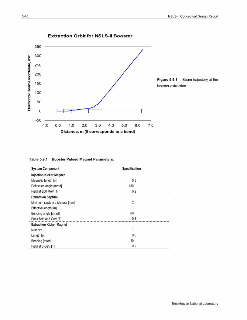
5-40 NSLS-II Conceptual Design Report
Brookhaven National Laboratory
Extraction Orbit for NSLS-II Booster
-50
0
50
100
150
200
250
300
350
-1.0 0.0 1.0 2.0 3.0 4.0 5.0 6.0 7.0
Distance, m (0 corresponds to a bend)
Hor
izon
tal B
eam
Coo
rdin
ate,
mm
Figure 5.9.1 Beam trajectory at the
booster extraction.
Table 5.9.1 Booster Pulsed Magnet Parameters.
System Component Specification
Injection Kicker Magnet Magnetic length [m] 0.5 Deflection angle [mrad] 150 Field at 200 MeV [T] 0.2 Extraction Septum Minimum septum thickness [mm] 2 Effective length [m] 1 Bending angle [mrad] 80 Peak field at 3 GeV [T] 0.8 Extraction Kicker Magnet Number 1 Length [m] 0.5 Bending [mrad] 10 Field at 3 GeV [T] 0.2
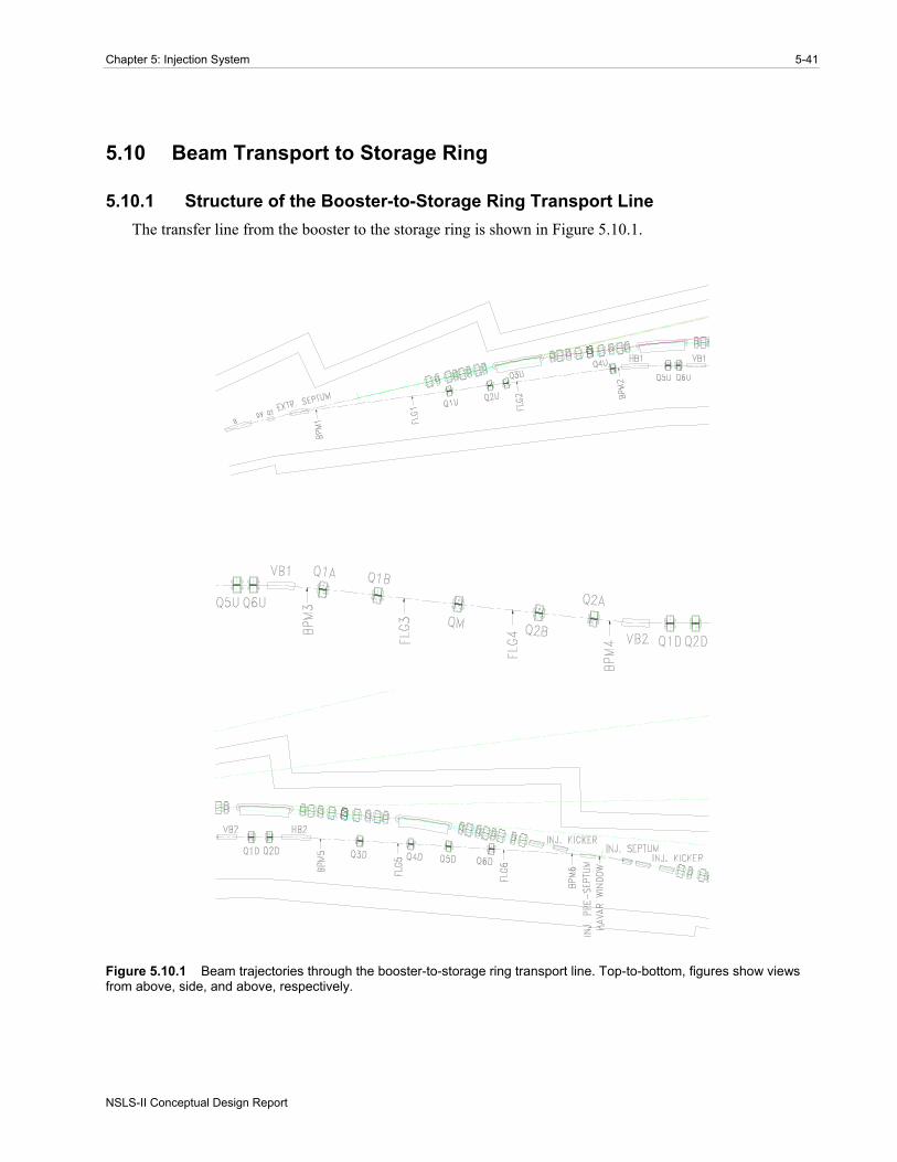
Chapter 5: Injection System 5-41
NSLS-II Conceptual Design Report
5.10 Beam Transport to Storage Ring
5.10.1 Structure of the Booster-to-Storage Ring Transport Line The transfer line from the booster to the storage ring is shown in Figure 5.10.1.
Figure 5.10.1 Beam trajectories through the booster-to-storage ring transport line. Top-to-bottom, figures show views from above, side, and above, respectively.

5-42 NSLS-II Conceptual Design Report
Brookhaven National Laboratory
Conceptually, the transport line consists of three parts. The first part starts from the extraction septum and ends by the first horizontal dipole. Four quadrupoles located between these two elements preserve full achromaticity of the beam transport, canceling the horizontal dispersion at the end of the dipole.
The second part corresponds to a vertical dog leg, which is made fully achromatic as well, by using five quadrupoles located between two vertical dipoles. The vertical dispersion is matched to zero value at the end of the second part.
The third part, like the first one, serves as an achromatic bend, bringing the beam to the injection septum in the storage ring.
Quadrupole doublets inserted in the dispersion-free regions help to match the beta functions between various parts of the transport line and optimize the beta functions at the injection point.
Three pairs of trim magnets (two for each part of the transport line) are included for adjustment of the beam trajectory in the transport line. Six flags, accompanied by six beam position monitors, will be used to measure the beam position and size (Table 5.10.1).
Table 5.10.1 Magnet Parameters of the Booster-to-Storage Ring Transport Line.
Dipole Quadrupole HV Trim Number required 4 17 6 Field strength at 3 GeV <0.8 T <25 T/m <1 T Length [m] 1-1.5 0.3 Gap height or diameter [mm] 35 35 –
In summary, the trajectory of the electron beam matches the storage ring injection straight, with the help of four bending magnets. Matching of the machine functions is accomplished with 17 quadrupoles. The machine functions are shown in Figure 5.10.2, and beam sizes along the transport line are shown in Figure 5.10.3.
5.10.2 Booster-to-Storage Ring Transport Line Power Supplies Power supplies for the transport line magnets are listed in Table 5.10.2.
Table 5.10.2 Booster-to-Storage Ring Transport Line Power Supplies.
Function Qty. Volts Amps Magnet supplies Dipole 4 7.3 175 BX-B1 to 4 Quadrupole 17 20 150 BX-QD1 to 8, LB-QF1 to 9 Trim 6 20.0 20.0 BX-V1 to 6, BXH1 to 6 Extraction kicker 1 12000 0.100 BXEKF Septum 2 800 1.500 BXISH1, BXISH2 Injection Kicker 1 5000 0.100 BXIBF
The supplies will be operated around a static operating point, eliminating the need for significant voltage head room. For energy savings, we anticipate that the supply’s output will be lowered during the dwell time in top-off mode and brought back to the operating point slightly before the top-off cycle. Unmodified commercial power supplies are currently used at NSLS in its transfer lines and are analog programmed by 14-bit digital-to-analog converters. The supplies are operated in current mode with shunt feedbacks.

Chapter 5: Injection System 5-43
NSLS-II Conceptual Design Report
Figure 5.10.2 Twiss parameters along the B–SR transfer line.
Figure 5.10.3 RMS beam sizes along the B–SR transfer line.
5.10.3 Power Supply Control Either a micro-controller or PLC will provide an analog input to power supply programming interface and
control the setpoint with a DAC resolution of at least 16 bits. Both the output voltage and current will be read back by a 16 bit ADC with a speed greater than 1 kHz.
Long-term monitoring of drift will be done using an independent external shunt connected to a high-precision analog channel.

5-44 NSLS-II Conceptual Design Report
Brookhaven National Laboratory
5.11 Diagnostics and Instrumentation
5.11.1 Scope This section describes diagnostics and instrumentation for the booster ring. The following parameters will
be monitored:
orbit working point (tunes in both planes) circulating current and filling pattern emittances beam losses around the booster bunch length
Booster diagnostics are summarized in Table 5.11.1.
Table 5.11.1 Beam Diagnostics for the Booster Ring.
Monitor Quantity Beam parameter DC current transformer 1 Beam current 4-button pick-ups 75 Beam position Fluorescent flags 4 Injection position, profile Stripline set and amplifier 2 Betatron tune Loss Monitor 30 Beam losses Fast current transformer 1 Filling pattern Optical beamline with streak-camera 1 Bunch length Firewire camera 1 Beam position, profile
5.11.2 Flags Four fluorescent flags will be used to observe shape and position of the injected electron beam during the
first turn. The flag material will be YAG:Ce. This was chosen because it results in an excellent resolution of the beam image and exhibits high sensitivity and high radiation hardness.
5.11.3 Orbit Correction The booster orbit will be monitored with 75 pick-up electrodes instrumented with RF BPM receivers. RF
BPMs are widely used for accelerators and have the specifications shown in Table 5.11.2 [5.27]:
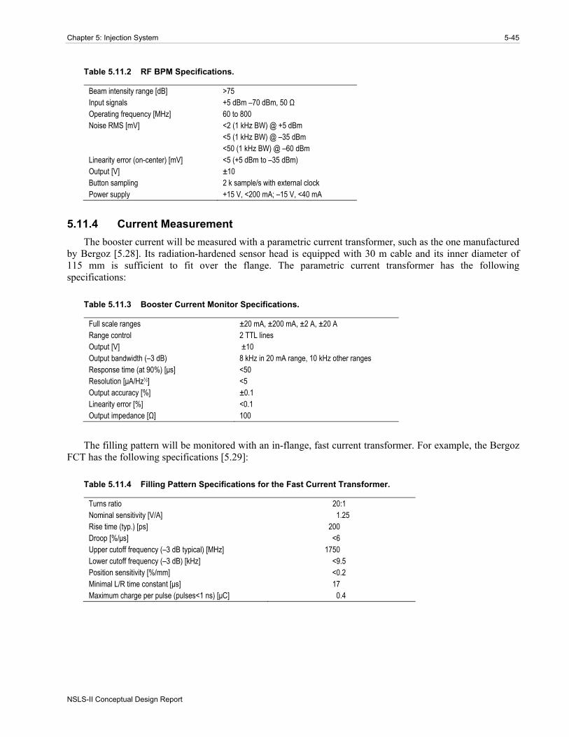
Chapter 5: Injection System 5-45
NSLS-II Conceptual Design Report
Table 5.11.2 RF BPM Specifications.
Beam intensity range [dB] >75 Input signals +5 dBm –70 dBm, 50 Ω Operating frequency [MHz] 60 to 800 Noise RMS [mV] <2 (1 kHz BW) @ +5 dBm <5 (1 kHz BW) @ –35 dBm <50 (1 kHz BW) @ –60 dBm Linearity error (on-center) [mV] <5 (+5 dBm to –35 dBm) Output [V] ±10 Button sampling 2 k sample/s with external clock Power supply +15 V, <200 mA; –15 V, <40 mA
5.11.4 Current Measurement The booster current will be measured with a parametric current transformer, such as the one manufactured
by Bergoz [5.28]. Its radiation-hardened sensor head is equipped with 30 m cable and its inner diameter of 115 mm is sufficient to fit over the flange. The parametric current transformer has the following specifications:
Table 5.11.3 Booster Current Monitor Specifications.
Full scale ranges ±20 mA, ±200 mA, ±2 A, ±20 A Range control 2 TTL lines Output [V] ±10 Output bandwidth (–3 dB) 8 kHz in 20 mA range, 10 kHz other ranges Response time (at 90%) [μs] <50 Resolution [μA/Hz½] <5 Output accuracy [%] ±0.1 Linearity error [%] <0.1 Output impedance [Ω] 100
The filling pattern will be monitored with an in-flange, fast current transformer. For example, the Bergoz FCT has the following specifications [5.29]:
Table 5.11.4 Filling Pattern Specifications for the Fast Current Transformer.
Turns ratio 20:1 Nominal sensitivity [V/A] 1.25 Rise time (typ.) [ps] 200 Droop [%/μs] <6 Upper cutoff frequency (–3 dB typical) [MHz] 1750 Lower cutoff frequency (–3 dB) [kHz] <9.5 Position sensitivity [%/mm] <0.2 Minimal L/R time constant [μs] 17 Maximum charge per pulse (pulses<1 ns) [μC] 0.4

5-46 NSLS-II Conceptual Design Report
Brookhaven National Laboratory
5.11.5 Bunch Length Measurement The synchrotron radiation from one of the bends will be used for bunch-length measurements with the
help of a streak camera [5.30]. Its specifications are shown in Table 7.8.3.
5.11.6 Tune Measurement System The fractional tune measurement system will be based on real-time spectral analysis of the signal induced
on the strip-lines by the electron beam. Electron beam motion will be excited by broadband noise generator with fixed cutoff frequencies. The real-time spectrum analyzer will be used to observe tune evolution along the ramp.
5.11.7 Beam Loss Monitors The beam loss monitors will have two p-i-n photodiodes mounted face to face for coincidence detection
of charged particles. Coincidence counting makes them insensitive to the synchrotron radiation photons. The widely used Bergoz BLM specifications are as follows [5.31]:
Table 5.11.5 Beam Loss Monitor Specifications.
Single particle detection efficiency [%] >30 p-i-n photodiode surface [mm2] 7.34 Maximum count rate [MHz] >10 Spurious count rate [Hz] <0.1 Output positive TTL, 50 Ω Cable driving capability >200 m RG213 Power supply +5 V, 170 mA; –5 V, 80 mA; +24 V, 1 mA Size [mm] 69 x 34 x 8
5.11.8 Visible SR Diagnostics The synchrotron radiation from the bending magnet will be used for beam observation with CCD
cameras. The beam image will be analyzed for the emittance measurements and also will provide information on the beam position and stability during the ramp.
References
[5.1] http://accelconf.web.cern.ch/AccelConf/e04/PAPERS/THPLT186.PDF [5.2] T. Shaftan, et al., “Design of 3 GeV Booster for NSLS-II,” Proc. of PAC-2005, p. 3473. [5.3] A. Setty, et al., “Commissioning of the 100 MeV Preinjector HELIOS for the SOLEIL Synchrotron,”
EPAC06. [5.4] EIMAC, CPI, Eimac Division, Palo Alto, CA. [5.5] W. B. Herrmannsfeldt, “EGUN – An Electron Optics and Gun Design Program,” SLAC 331, 1988. [5.6] Parmela, ver. 3, by Lloyd M. Young , Documentation by James H. Billen, Los Alamos Nat. Lab. [5.7] C. Christou, et al., “Commissioning of the Diamond Pre-Injector Linac,” EPAC06. [5.8] C.W. Allen et al., “PEP-II Hardware Reliability,” SLAC-PUB-10835. [5.9] S.S. Park et al., “Reliability Analysis of the PLS Klystron-Modulator System,” Proc. of the Second
APAC, Bejing, 2001. [5.10] http://www.sc-nova.com/
Chapter 5: Injection System 5-47
NSLS-II Conceptual Design Report
[5.11] W. Crewson, “A new solid-state high-power pulsed modulator,” 5th Modulator-Klystron Workshop for Future Linear Colliders MDK-2001 Geneva, 25-27 April 2001.
[5.12] J. Rose, et al., “Radio-Frequency Control System for the DUVFEL,” PAC03. http://epaper.kek.jp/p03/PAPERS/TPAB006.PDF
[5.13] B. Fellenz, and J. Crisp, “An Improved Resistive Wall Monitor,” Proc. of Beam Instrumentation Workshop 1998, AIP Conf. Proc. 451, pp. 446–453.
[5.14] http://www.bergoz.com [5.15] E. Johnson, W.S. Graves, and K.E. Robinson, “Periscope Pop-In Monitor,” Proc. of Beam
Instrumentation Workshop 1998, AIP Conf. Proc. 451, pp. 479–484. [5.16] http://www.gmw.com/beam_diagnostics/Bergoz/bpm/pdf/GMW-DS-BPM-UHV-50_B.pdf [5.17] A. Kalinin, “Log-Ratio Beam Position Monitor,” Proc. of Beam Instrumentation Workshop2002, AIP
Conf. Proc. 648, pp. 384–392. [5.18] G. Mülhaupt, “A Few Design Considerations for Injector Synchrotrons for Synchrotron Light
Sources,” Internal Report ESRF/MACH-INJ/94-13, ESRF Grenoble 1994A. [5.19] W.D. Klotz, G. Mülhaupt, “A Novel Low Emittance Lattice for High Brilliance Electron Beams.
Workshop on Fourth Generation Light Sources, 1992, Stanford, CA [5.20] W. Joho, M. Munoz, and A. Streun, “The SLS booster synchrotro,” Nucl. Instrum. & Meth. A 562
(2006), p.1. [5.21] V. Tsakanov, et al., “Status of the 3 GeV CANDLE Synchrotron Light Source Facility project,” Proc.
of EPAC-2004, Lucerne, p. 2254. [5.22] D. Einfeld, et al., “Progress of the Synchrotron Light Source ALBA,” Proc. of PAC-2005, Knoxville,
TN, p. 4203. [5.23] G.-H. Luo, et al., Design Consideration of a Booster for Taiwan Photon Source, Proc. of PAC-2005,
Knoxville, TN, p. 2992. [5.24] J. Galayda, et al., “The NSLS Booster Synchrotron,” Proc. of PAC-1979, p. 3839. [5.25] M. Munoz and V. Joho, Eddy current effects in the SLS booster:
http://slsbd.psi.ch/pub/slsnotes/tmeta9810/eddy.html [5.26] H. Gerke, H.P. Scholz, M. Sommerfeld, A. Zolfaghari, “Das Petra Cavity,” Interner Bericht DESY
PET-77/08, August 1977. [5.27] http://www.bergoz.com/products/MX-BPM/MX-BPM.html [5.28] http://www.bergoz.com/products/NPCT/PCT-downloads/files/NPCTflyer.pdf [5.29] http://www.bergoz.com/products/FCT/d-fct.html [5.30] http://sales.hamamatsu.com/en/products/system-division/ultra-fast/streak-systems.php [5.31] http://www.bergoz.com/products/BLM/BLM.html