Embed Size (px)
Citation preview
Introduction to G-Code Programming
Computer Integrated Manufacturing
Unit 2: CNC Machining
In this lesson:Review Coordinate Geometry Basics
Identify common Terminology
Examine G and M - Code language
Provide opportunities for Review and Practice
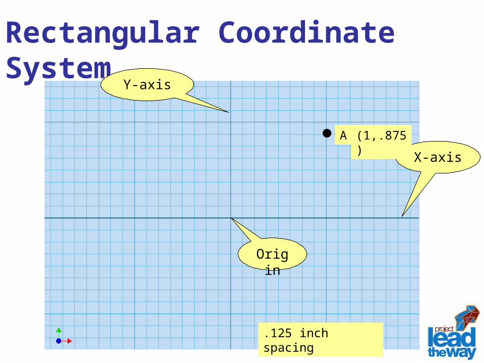
Rectangular Coordinate System
X-axis
Y-axis
Origin
.125 inch spacing
A (X,Y)(1,.875)
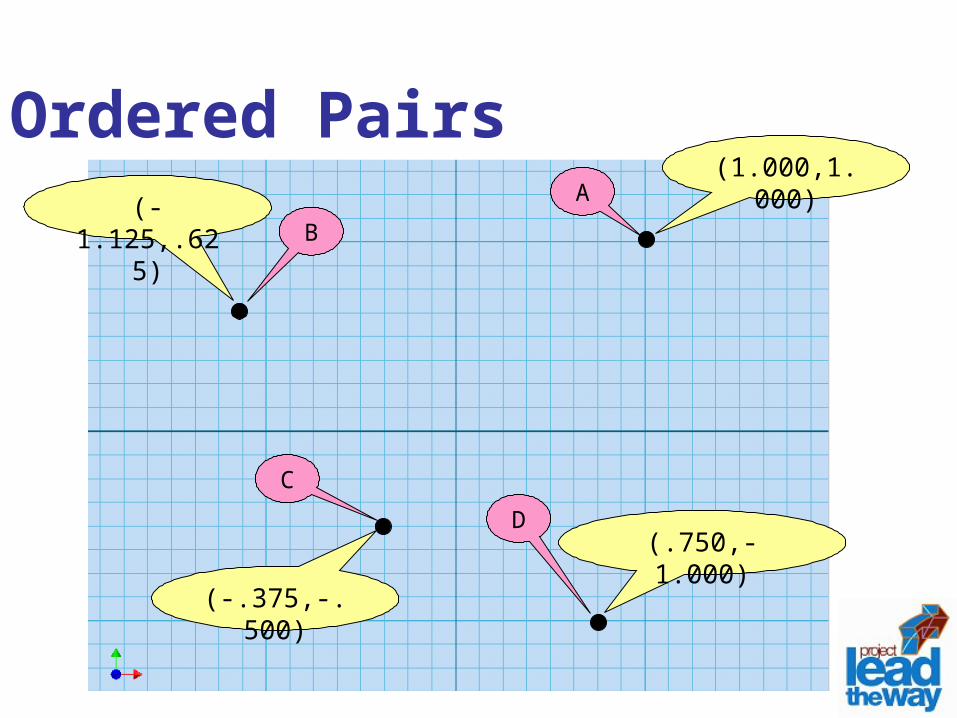
(1.000,1.000)(-1.125,.625)
(-.375,-.500)
(.750,-1.000)
Ordered PairsA
B
C
D
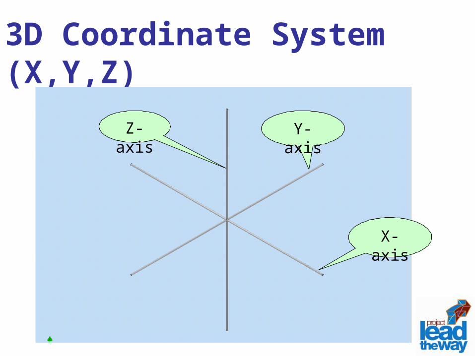
3D Coordinate System (X,Y,Z)
X-axis
Z-axis
Y-axis
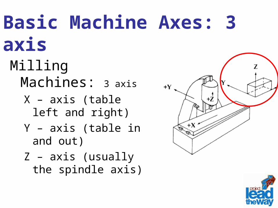
Basic Machine Axes: 3 axisMilling Machines: 3 axis
X – axis (table left and right)
Y – axis (table in and out)Z – axis (usually the
spindle axis)
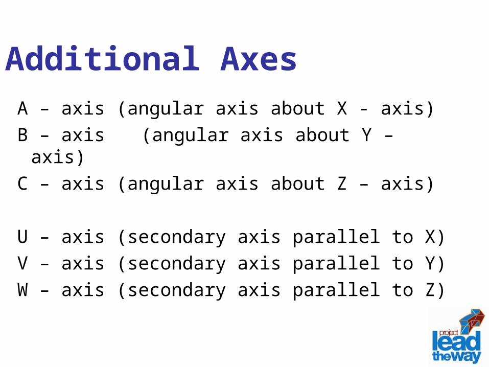
Additional AxesA – axis (angular axis about X - axis)B – axis (angular axis about Y – axis)C – axis (angular axis about Z – axis)
U – axis (secondary axis parallel to X)V – axis (secondary axis parallel to Y)W – axis (secondary axis parallel to Z)
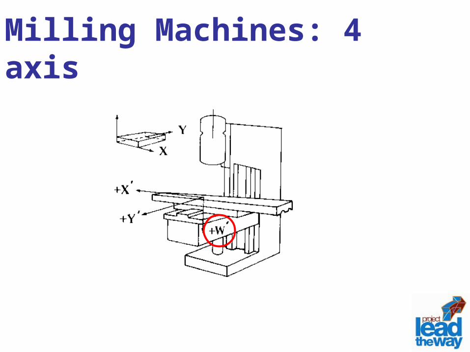
Milling Machines: 4 axis
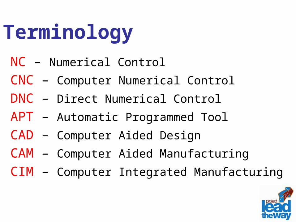
TerminologyNC – Numerical ControlCNC – Computer Numerical ControlDNC – Direct Numerical ControlAPT – Automatic Programmed ToolCAD – Computer Aided DesignCAM – Computer Aided ManufacturingCIM – Computer Integrated Manufacturing
Download Code Sheet
Click here to open Code Sheet
G - Code ProgrammingG – Code Programming
Originally called the “Word Address” programming format.
Processed one line at a time sequentially.
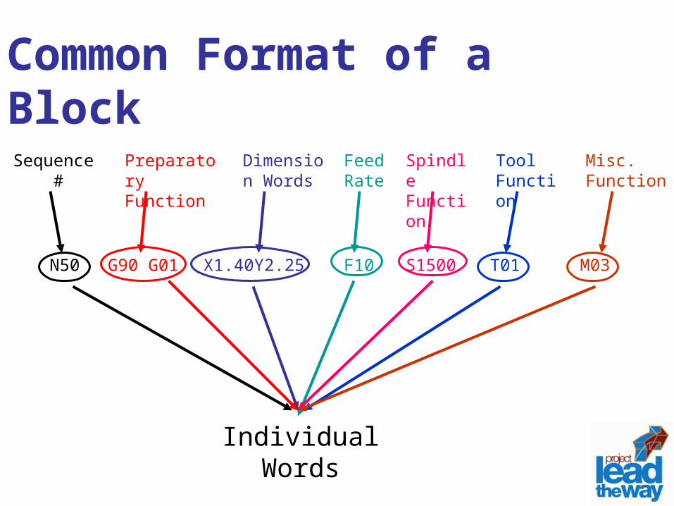
Common Format of a BlockSequence
#Preparatory Function
Dimension Words
Feed Rate
Spindle Function
Tool Function
Misc. Function
N50 G90 G01 X1.40Y2.25 F10 S1500 T01 M03
Individual Words
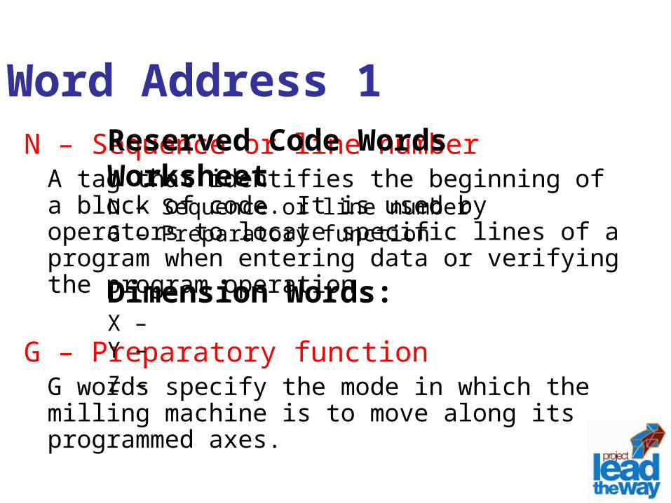
Word Address 1N – Sequence or line number
A tag that identifies the beginning of a block of code. It is used by operators to locate specific lines of a program when entering data or verifying the program operation.
G – Preparatory functionG words specify the mode in which the milling machine is to move along its programmed axes.
Reserved Code Words WorksheetN – Sequence or line numberG – Preparatory function
Dimension Words:X – Y – Z –
Word Address 2Dimension Words
X – Distance or position in X directionY – Distance or position in Y directionZ – Distance or position in Z direction
M – Miscellaneous functionsM words specify CNC machine functions not related to dimensions or axial movements.
F – Feed rate (inches per minute or millimeters per minute)Rate at which cutting tool moves along an axis.
S – Spindle speed (rpm – revolutions per minute)Controls spindle rotation speed.
T – Tool numberSpecifies tool to be selected.
Word Address 3
I – Circular cutting reference for x axis
J – Circular cutting reference for y axis
K – Circular cutting reference for z axis
Word Address 4
G WordG words or codes tell the machine to
perform certain functions. Most G words are modal which means they remain in effect until replaced by another modal G code.
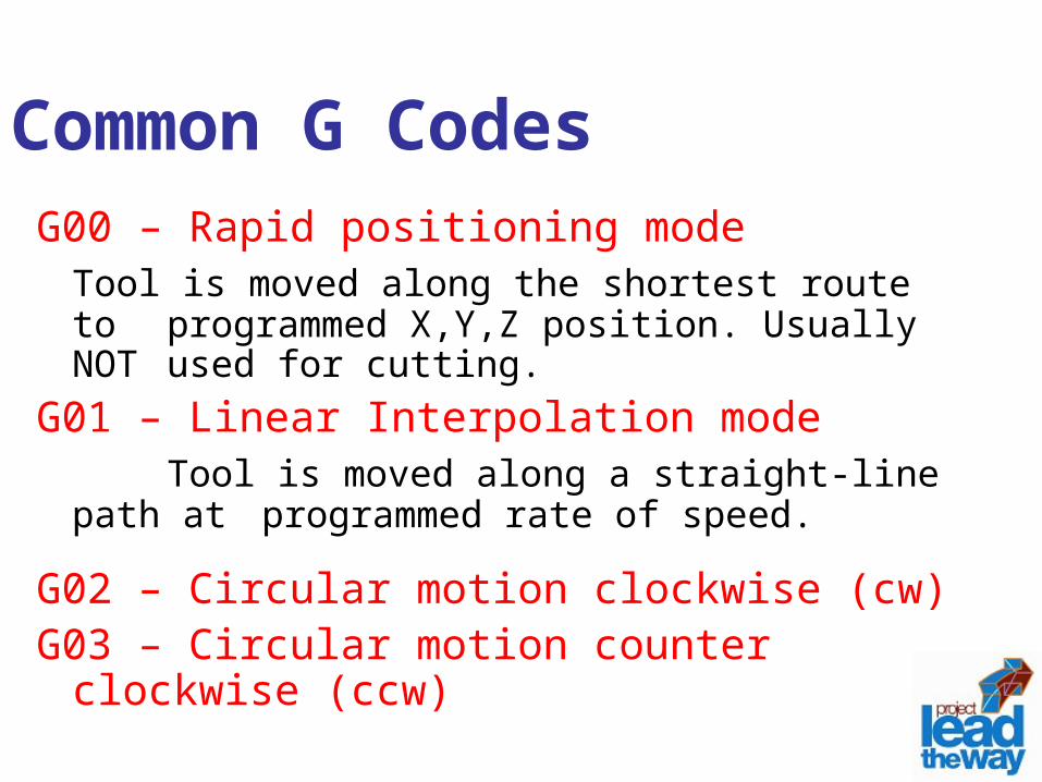
Common G CodesG00 – Rapid positioning mode
Tool is moved along the shortest route to programmed X,Y,Z position. Usually NOT used for cutting.
G01 – Linear Interpolation mode Tool is moved along a straight-line path at
programmed rate of speed.
G02 – Circular motion clockwise (cw)G03 – Circular motion counter clockwise
(ccw)
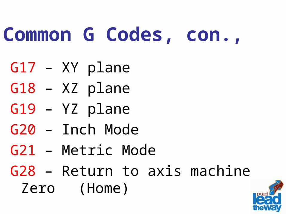
Common G Codes, con.,G17 – XY planeG18 – XZ planeG19 – YZ planeG20 – Inch ModeG21 – Metric ModeG28 – Return to axis machine Zero
(Home)
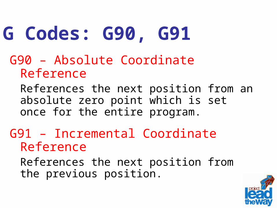
G Codes: G90, G91G90 – Absolute Coordinate Reference
References the next position from an absolute zero point which is set once for the entire program.
G91 – Incremental Coordinate ReferenceReferences the next position from the previous position.
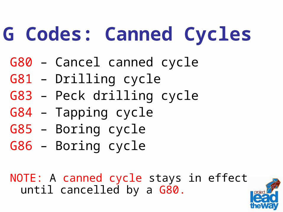
G Codes: Canned CyclesG80 – Cancel canned cycleG81 – Drilling cycleG83 – Peck drilling cycleG84 – Tapping cycleG85 – Boring cycleG86 – Boring cycle
NOTE: A canned cycle stays in effect until cancelled by a G80.
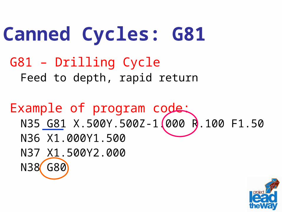
Canned Cycles: G81G81 – Drilling Cycle
Feed to depth, rapid return
Example of program code:N35 G81 X.500Y.500Z-1.000 R.100 F1.50N36 X1.000Y1.500N37 X1.500Y2.000N38 G80
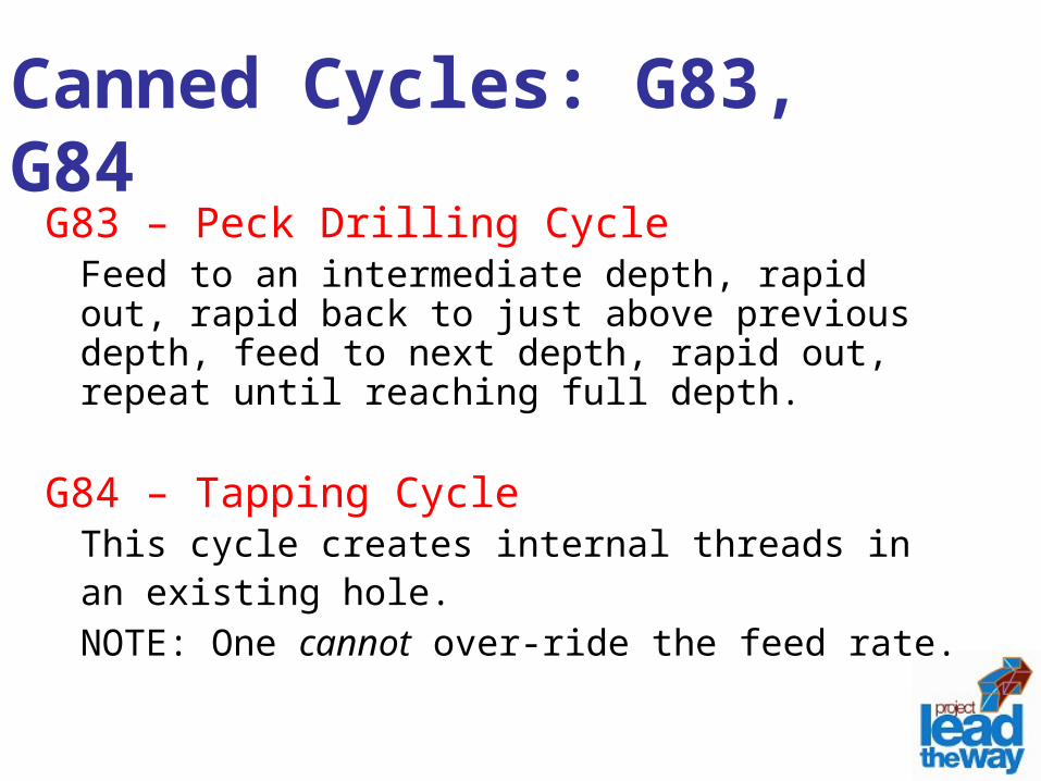
Canned Cycles: G83, G84G83 – Peck Drilling Cycle
Feed to an intermediate depth, rapid out, rapid back to just above previous depth, feed to next depth, rapid out, repeat until reaching full depth.
G84 – Tapping CycleThis cycle creates internal threads in an existing hole. NOTE: One cannot over-ride the feed rate.
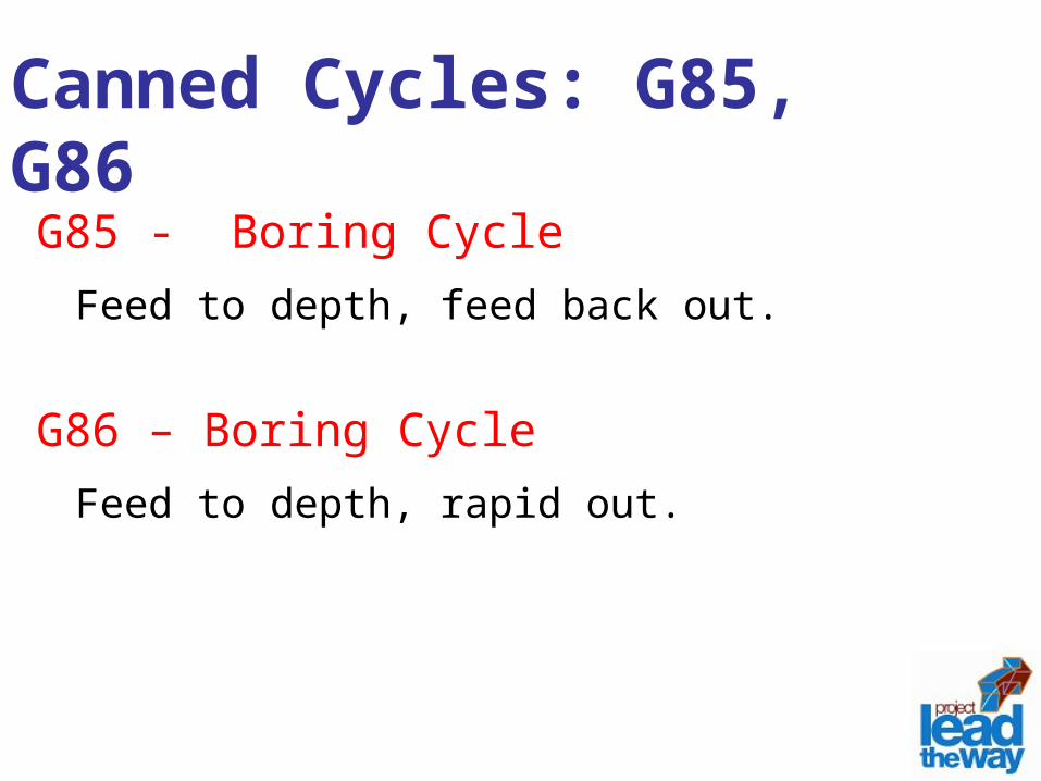
Canned Cycles: G85, G86G85 - Boring Cycle
Feed to depth, feed back out.
G86 – Boring CycleFeed to depth, rapid out.
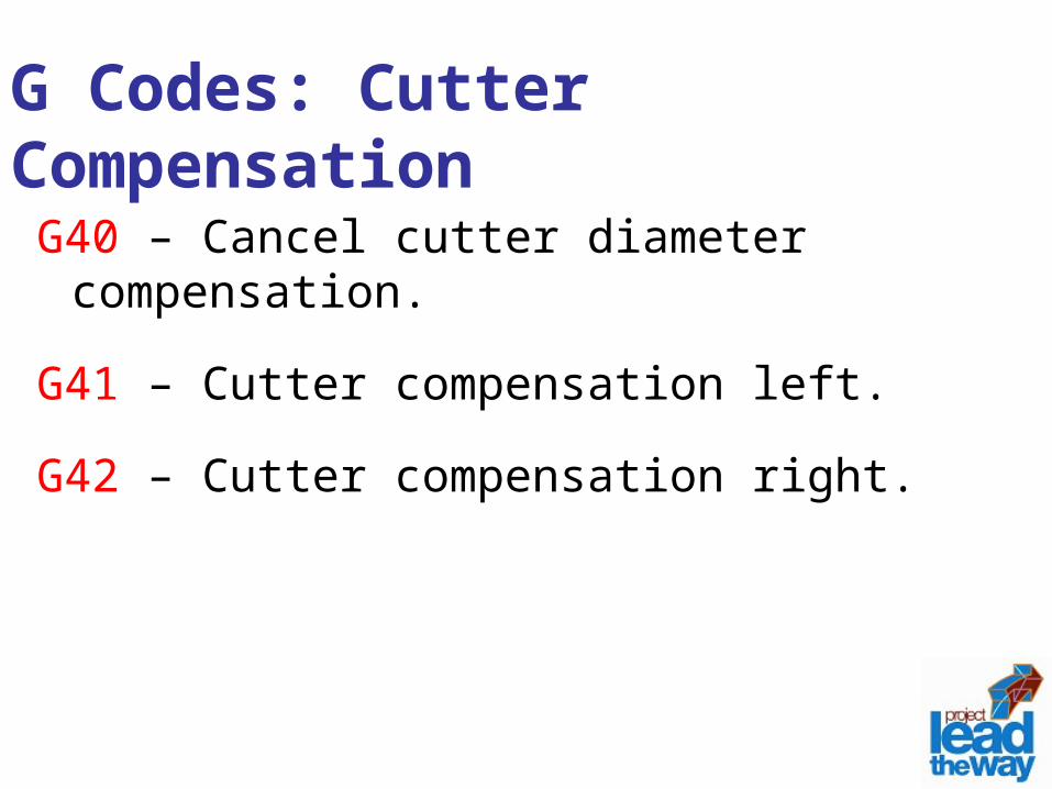
G Codes: Cutter CompensationG40 – Cancel cutter diameter
compensation.
G41 – Cutter compensation left.
G42 – Cutter compensation right.
M WordM words tell the machine to perform
certain machine related functions, such as: turn spindle on/off, coolant on/off, or stop/end program.
Professional Development ID Code: 6006
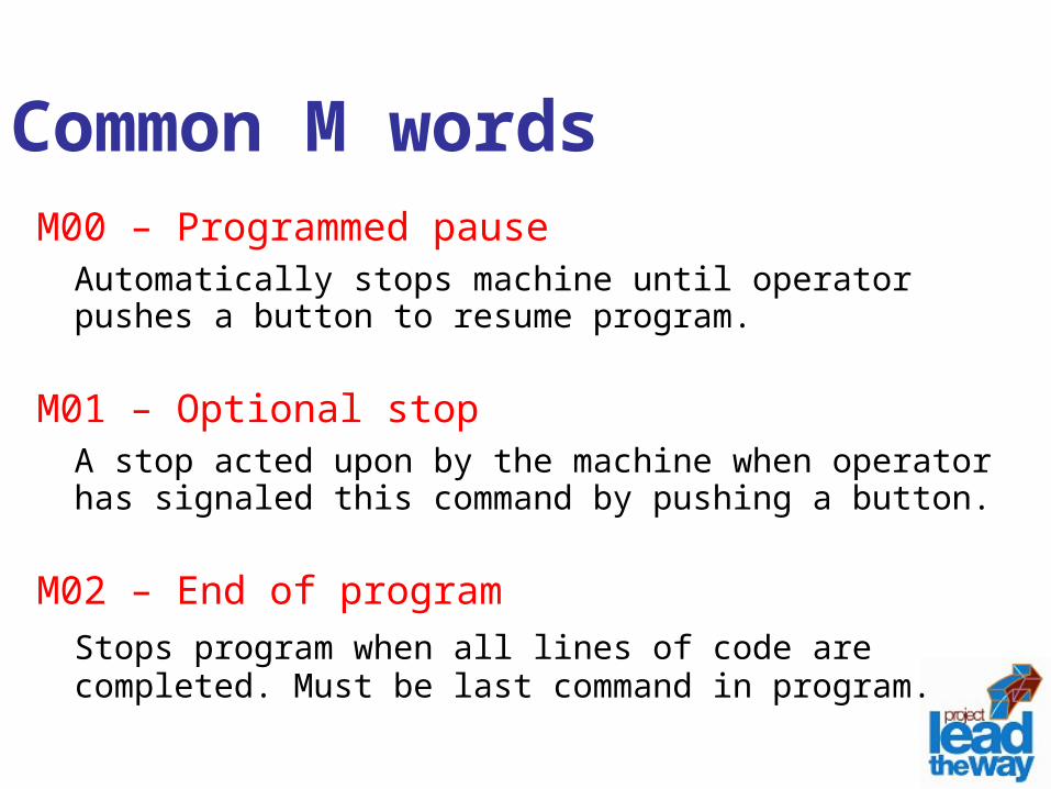
Common M wordsM00 – Programmed pause
Automatically stops machine until operator pushes a button to resume program.
M01 – Optional stopA stop acted upon by the machine when operator has signaled this command by pushing a button.
M02 – End of programStops program when all lines of code are completed. Must be last command in program.
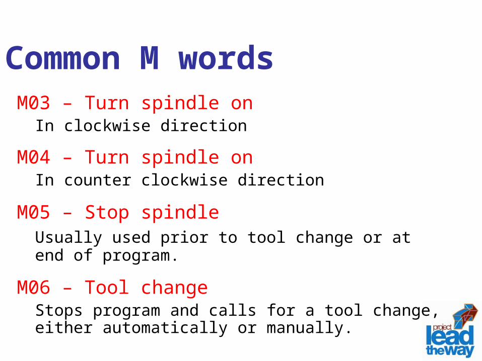
M03 – Turn spindle on In clockwise direction
M04 – Turn spindle on In counter clockwise direction
M05 – Stop spindleUsually used prior to tool change or at end of program.
M06 – Tool changeStops program and calls for a tool change, either automatically or manually.
Common M words
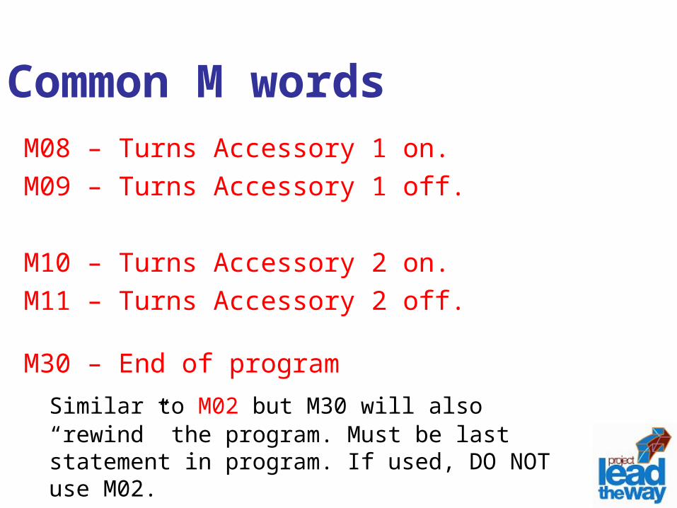
M08 – Turns Accessory 1 on. M09 – Turns Accessory 1 off.
M10 – Turns Accessory 2 on. M11 – Turns Accessory 2 off.
M30 – End of program Similar to M02 but M30 will also “rewind” the program. Must be last statement in program. If used, DO NOT use M02.
Common M words
Zero PointsPart Zero
– Used for absolute programming mode.– Usually a position on the part that all absolute
coordinates are referenced to. – Changes with different parts and programs.
Machine Zero or Machine Home Position – Fixed for each machine from the manufacturer.– Not changeable.
Cutter Path GenerationCutter path is generated by moving the
tool from point to point. The points are previously defined from the part drawing dimensions.
Each line of code will show the destination point of where the tool will go to.
InterpolationMethod of determining intermediate
points along a cutting path.
Two methods:• Linear interpolation – cut a path along a
specified angle at a specified feed rate.• Circular interpolation – cut a path along an arc
or circle at a specified feed rate.
Axis movements: Caution!Multiple axis movements are possible.
“Best Practice” is NOT to make a 3-axis movement using one line of code.
Move to position using two axes, X,Y; then move the Z with an additional line of code.
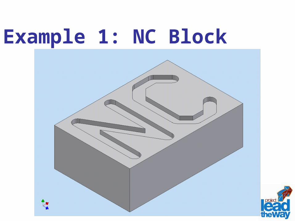
Example 1: NC Block
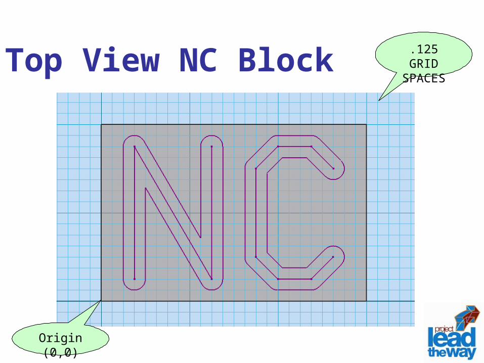
Top View NC Block .125 GRID SPACES
Origin (0,0)
Download Worksheet
Click here to open Practice Exercises
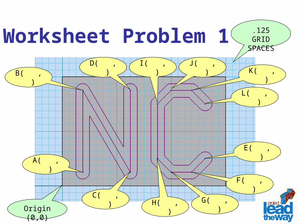
Worksheet Problem 1 .125 GRID SPACES
Origin (0,0)
E( , )
B( , )
C( , )
D( , )
A( , )
F( , )
G( , )H( , )
I( , ) J( , )K( , )
L( , )
Pause Lesson
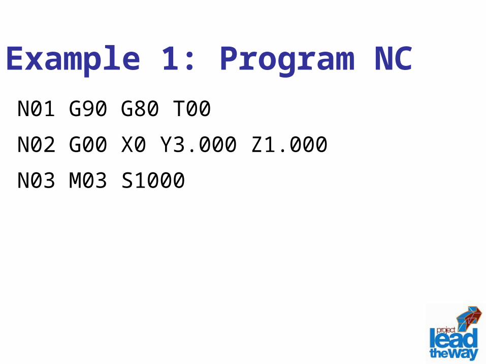
Example 1: Program NCN01 G90 G80 T00
N02 G00 X0 Y3.000 Z1.000
N03 M03 S1000
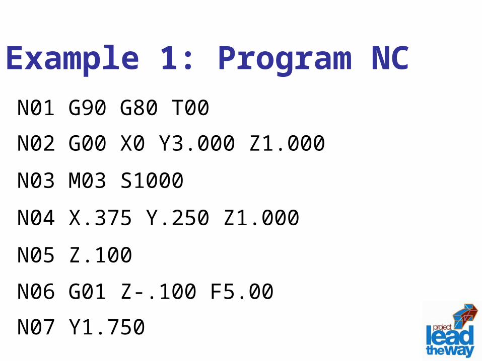
Example 1: Program NCN01 G90 G80 T00
N02 G00 X0 Y3.000 Z1.000
N03 M03 S1000
N04 X.375 Y.250 Z1.000
N05 Z.100
N06 G01 Z-.100 F5.00
N07 Y1.750
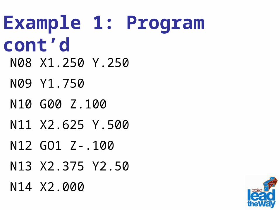
Example 1: Program cont’dN08 X1.250 Y.250
N09 Y1.750
N10 G00 Z.100
N11 X2.625 Y.500
N12 GO1 Z-.100
N13 X2.375 Y2.50
N14 X2.000
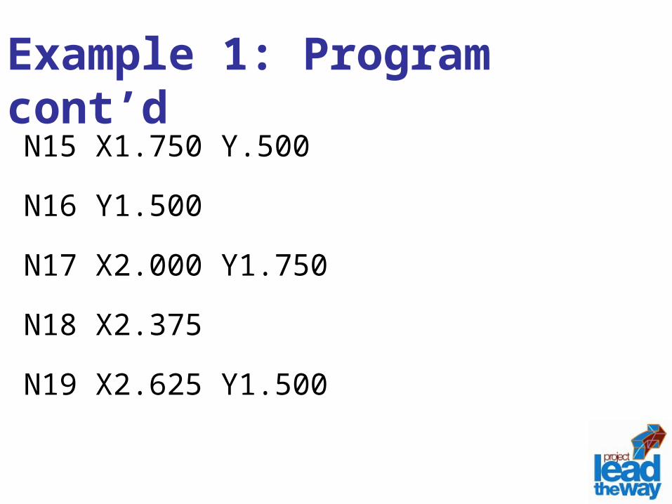
Example 1: Program cont’dN15 X1.750 Y.500
N16 Y1.500
N17 X2.000 Y1.750
N18 X2.375
N19 X2.625 Y1.500
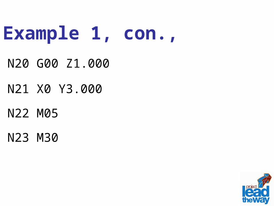
Example 1, con.,N20 G00 Z1.000
N21 X0 Y3.000
N22 M05
N23 M30
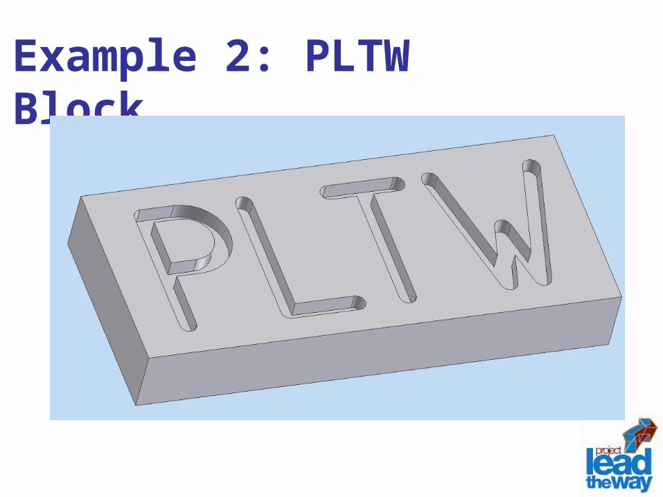
Example 2: PLTW Block
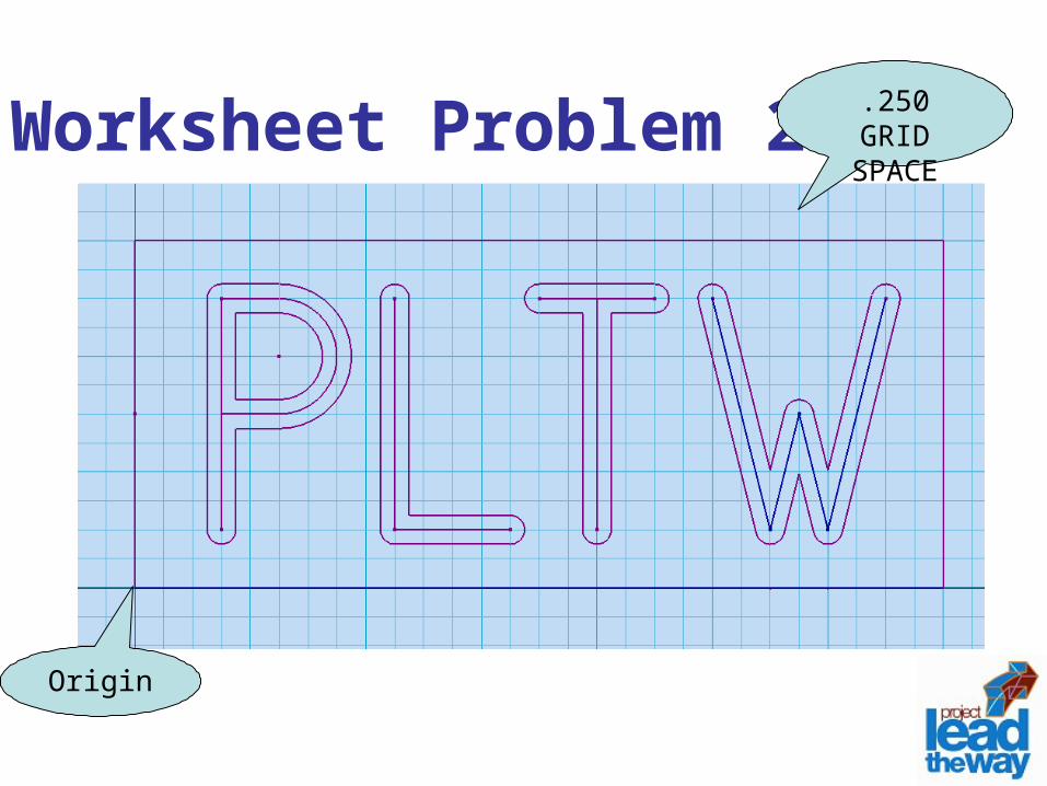
Worksheet Problem 2
Origin
.250 GRID SPACE
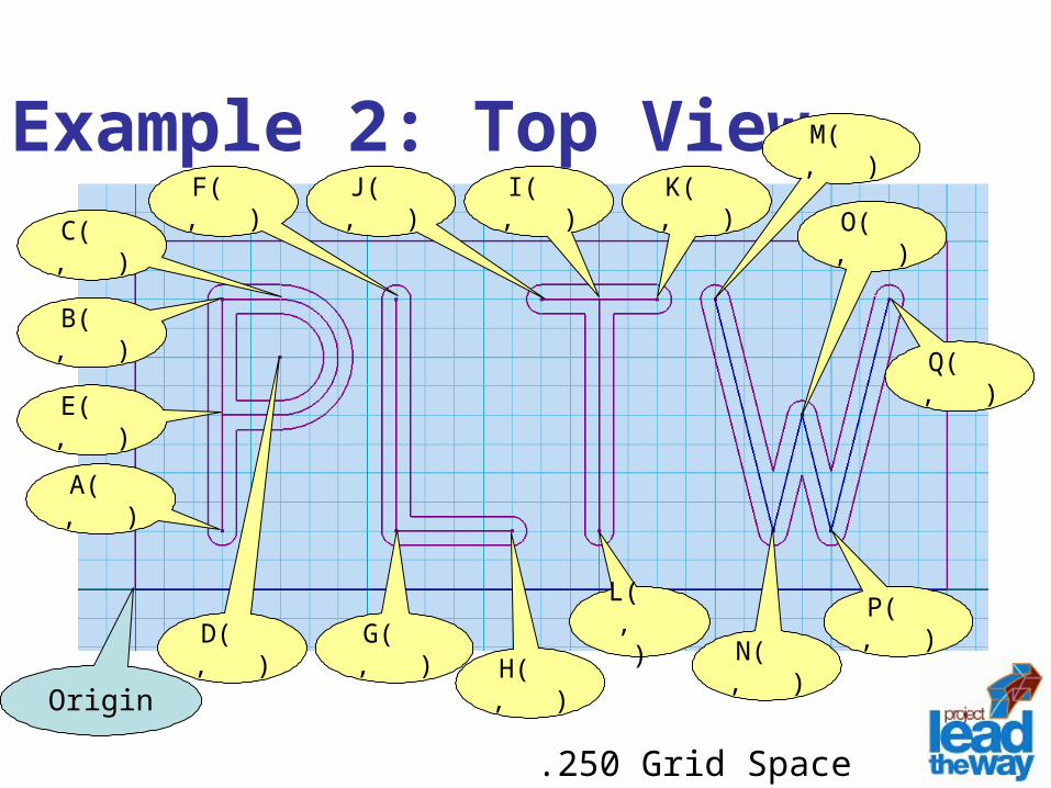
Example 2: Top View
Origin
A( , )
E( , )
D( , )
C( , )
B( , )
I( , )
H( , )
G( , )
F( , )
.250 Grid Space
L( , )
K( , )J( , )
P( , )
O( , )
N( , )
M( , )
Q( , )

Pause Lesson
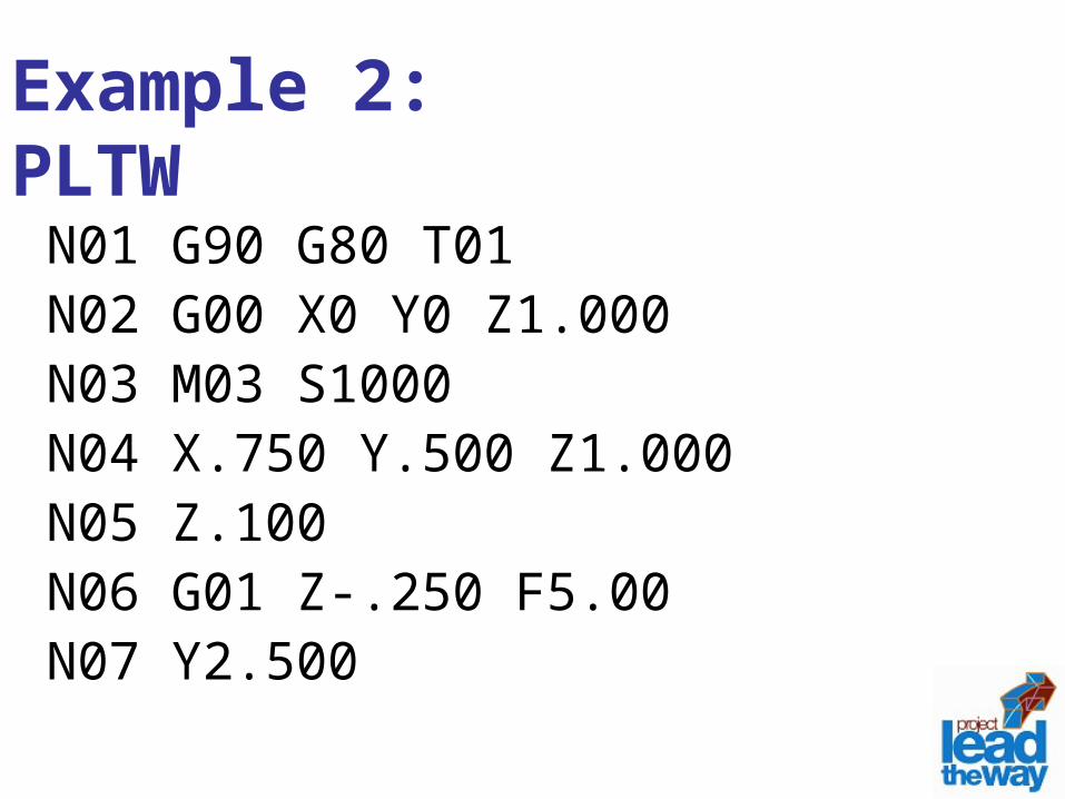
Example 2: PLTWN01 G90 G80 T01N02 G00 X0 Y0 Z1.000N03 M03 S1000N04 X.750 Y.500 Z1.000N05 Z.100N06 G01 Z-.250 F5.00N07 Y2.500
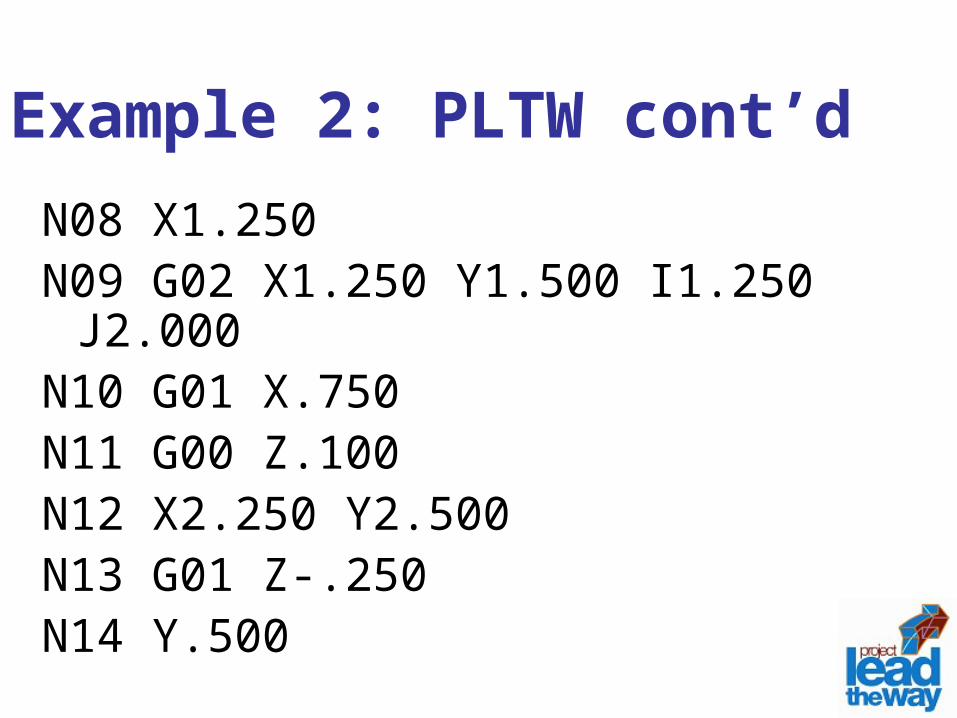
Example 2: PLTW cont’dN08 X1.250N09 G02 X1.250 Y1.500 I1.250 J2.000N10 G01 X.750N11 G00 Z.100N12 X2.250 Y2.500N13 G01 Z-.250N14 Y.500
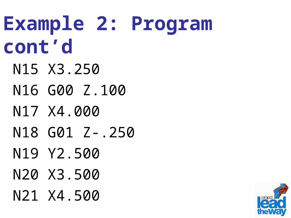
Example 2: Program cont’dN15 X3.250N16 G00 Z.100N17 X4.000N18 G01 Z-.250N19 Y2.500N20 X3.500N21 X4.500
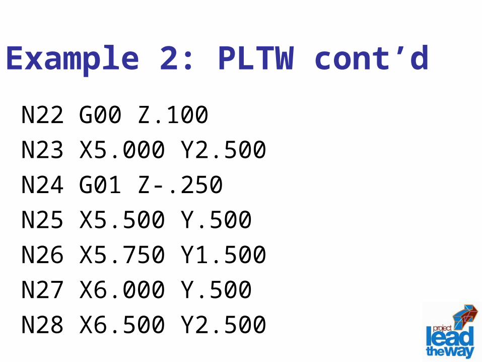
Example 2: PLTW cont’dN22 G00 Z.100N23 X5.000 Y2.500N24 G01 Z-.250N25 X5.500 Y.500N26 X5.750 Y1.500N27 X6.000 Y.500N28 X6.500 Y2.500
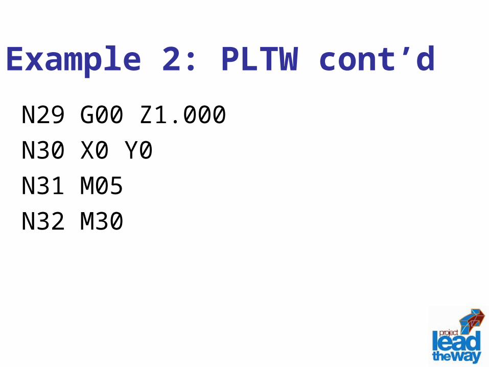
Example 2: PLTW cont’dN29 G00 Z1.000N30 X0 Y0N31 M05N32 M30
Curriculum Alignment:
Unit 2: CNC Machining
Section 2.3 – CNC Machining
PowerPoint – Introduction to CNC
PowerPoint – CNC Programming
References:
Oberg, E. & Jones F. D. & Horton, H. L. & Ryffell, H. H. (2000). Machinery’s Handbook, 26th ed., New York, NY: Industrial Press Inc.
Valentino, J.V. & Goldenberg, J. (2003). Introduction to Computer Numerical Control (CNC), 3rd ed., Upper Saddle River, NJ: Prentice Hall
Credits:Writer: Bob Arrendondo
Content Editor: Donna E. Scribner
Narration: Donna E. Scribner
PLTW Editor: Ed Hughes
Production: CJ Amarosa
Video Production: CJ Amarosa
Audio: CJ Amarosa
Project Manager: Donna E. Scribner