Embed Size (px)
Citation preview

Fluid Mechanics for Construction Chapter 5 – Energy Equation
P.5-1
5 ENERGY EQUATION OF FLUID MOTION 5.1 Introduction In order to develop the equations that describe a flow, it is assumed that fluids are subject to certain fundamental laws of physics. The pertinent laws are: 1. Conservation of mass; 2. Conservation of energy; 3. Conservation of momentum. These principles were initially developed for the case of a solid body and the application of these laws to a solid body is relatively straightforward since the body will be of measurable size and mass. However, it is not for a flowing fluid. Therefore, the equations should be modified before it can be applied in a flowing fluid. 5.2 Continuity Equation The principle of conservation of mass can be applied to a flowing fluid. Considering any fixed region in the flow constituting a control volume,
Mass of fluid entering per unit time
=
Mass of fluid leaving per unit time
+
Increase of mass of fluid in the control volume per unit time
Control Volumemass of fluidentering
mass of fluid leaving
For steady flow, the mass of fluid in the control volume remains constant and the relation reduces to
Mass of fluid entering per unit time
= Mass of fluid leaving per unit time
Fluid Mechanics for Construction Chapter 5 – Energy Equation
P.5-2
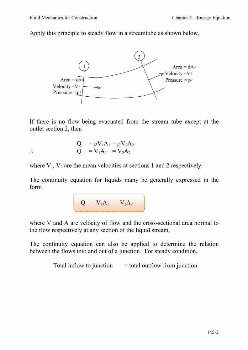
Apply this principle to steady flow in a streamtube as shown below,
1
2
Area = d A1
Velocity = V1
Pressure = p1
Area = d A2
Velocity = V2
Pressure = p2
If there is no flow being evacuated from the stream tube except at the outlet section 2, then Q = V1A1 = V2A2 Q = V1A1 = V2A2 where V1, V2 are the mean velocities at sections 1 and 2 respectively. The continuity equation for liquids many be generally expressed in the form where V and A are velocity of flow and the cross-sectional area normal to the flow respectively at any section of the liquid stream. The continuity equation can also be applied to determine the relation between the flows into and out of a junction. For steady condition, Total inflow to junction = total outflow from junction
Q = V1A1 = V2A2

Fluid Mechanics for Construction Chapter 5 – Energy Equation
P.5-3
A1
V1
Q1
A2
V2
Q2
A3
V3
Q3 1Q1 = 2Q2 + 3Q3 For an incompressible flow, 1 = 2 = 3, then Q1 = Q2 + Q3 or A1 V1 = A2 V2 + A3 V3 In general, if we consider flow towards the junction as positive and flow away for the junction as negative, then for steady flow at any junction the algebraic sum of all the mass flows must be zero: Q = 0 In differential form, the Continuity Equation becomes
0)()()(
zyx vz
vy
vxt
For incompressible flow, i.e. density of the fluid is constant, then
0
z
v
y
v
x
v zyx or 0 V
Fluid Mechanics for Construction Chapter 5 – Energy Equation
P.5-4
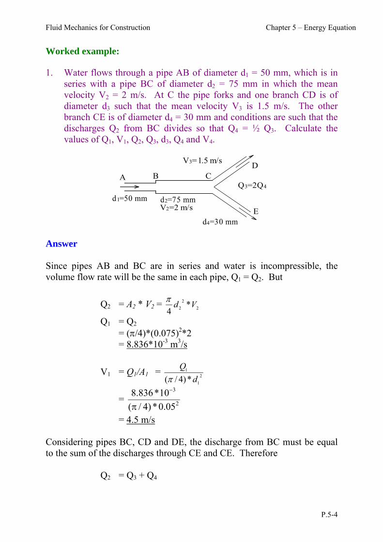
Worked example: 1. Water flows through a pipe AB of diameter d1 = 50 mm, which is in
series with a pipe BC of diameter d2 = 75 mm in which the mean velocity V2 = 2 m/s. At C the pipe forks and one branch CD is of diameter d3 such that the mean velocity V3 is 1.5 m/s. The other branch CE is of diameter d4 = 30 mm and conditions are such that the discharges Q2 from BC divides so that Q4 = ½ Q3. Calculate the values of Q1, V1, Q2, Q3, d3, Q4 and V4.
A B CD
E
d1=50 mm d2=75 mmV2=2 m/s
V3=1.5 m/s
d4=30 mm
Q3=2Q4
Answer Since pipes AB and BC are in series and water is incompressible, the volume flow rate will be the same in each pipe, Q1 = Q2. But
Q2 = A2 * V2 = 2
2
2 *4
Vd
Q1 = Q2 = (/4)*(0.075)2*2
= 8.836*10-3 m3/s
V1 = Q1/A1 = 2
1
1
*)4/( d
Q
= 2
3
05.0*)4/(
10*836.8
= 4.5 m/s Considering pipes BC, CD and DE, the discharge from BC must be equal to the sum of the discharges through CE and CE. Therefore Q2 = Q3 + Q4
Fluid Mechanics for Construction Chapter 5 – Energy Equation
P.5-5
And since Q4 = ½ Q3 Q2 = 1.5 Q3 Hence Q3 = Q2 / 1.5 = 8.836*10-3/1.5 = 5.891*10-3 m3/s & Q4 = ½ Q3 = 2.945*10-3 m3/s
Also, since Q3 = 3
2
3 *4
Vd
Hence d3 = 3
34
V
Q
= 5.1*
10*891.5*4 3
= 0.071 m
V4 = 2
4
4
*)4/( d
Q
= 2
3
03.0*)4/(
10*945.2
= 4.17 m/s
Fluid Mechanics for Construction Chapter 5 – Energy Equation
P.5-6
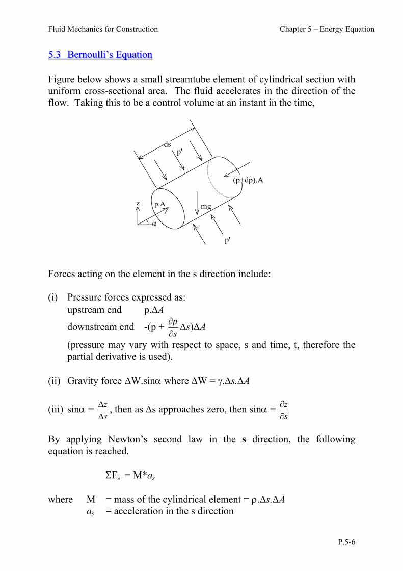
5.3 Bernoulli’s Equation Figure below shows a small streamtube element of cylindrical section with uniform cross-sectional area. The fluid accelerates in the direction of the flow. Taking this to be a control volume at an instant in the time,
p'
p'
ds
p.A
(p+dp).A
mg
z
Forces acting on the element in the s direction include: (i) Pressure forces expressed as: upstream end p.A
downstream end -(p + s
p
s)A
(pressure may vary with respect to space, s and time, t, therefore the partial derivative is used).
(ii) Gravity force W.sin where W = .s.A
(iii) sin = s
z
, then as s approaches zero, then sin = s
z
By applying Newton’s second law in the s direction, the following equation is reached. Fs = M*as where M = mass of the cylindrical element = .s.A as = acceleration in the s direction

Fluid Mechanics for Construction Chapter 5 – Energy Equation
P.5-7
Therefore, we arrive at the following equation by substituting the above expression into the above equation. saAsWAppAp *sin)(
saAss
zAsAp *
Divide the whole equation by s.A, and taking the limit as s0, then
s. = z) + ( aps
- Euler’s equation
By rewriting the acceleration term in a general form as follows:
sa = Dt
DV
= dt
dsVV
s +
t
For steady flow, 0 = t
V
Then sa = sV
V
By substituting the above expression into Euler’s equation we obtain the following
S
VVzp
s
= )(
Assuming the density of the fluid remains unchanged,
0 = )(2
+ s
z + 2V
ss
p
By integrating the above equation with respect to s we have,
p + z + 2 V2 = constant

Fluid Mechanics for Construction Chapter 5 – Energy Equation
P.5-8
or constant = g2
V + z +
p 2
The subscript s is usually omitted and V is used to represent the velocity in the direction of fluid flow. The term p/ - pressure head z - potential head (elevation head) V2/2g - velocity head The constant at the right hand side of the equation is the total head (total energy per unit weight) of the flow field. The equation is applicable when the flow is steady, non-viscous, and incompressible with the constant density. Under these conditions the total head at any point along a streamline of the flow field is the same. Bernoulli’s equation is an expression of the principle of conservation of energy. In most applications, Bernoulli’s equation is applied at two points in the flow field with z1 and z2 are referred to the same datum.
g
V + + z
γ
p =
g
V + + z
γ
p
22
2
22
2
2
11
1
Fluid Mechanics for Construction Chapter 5 – Energy Equation
P.5-9
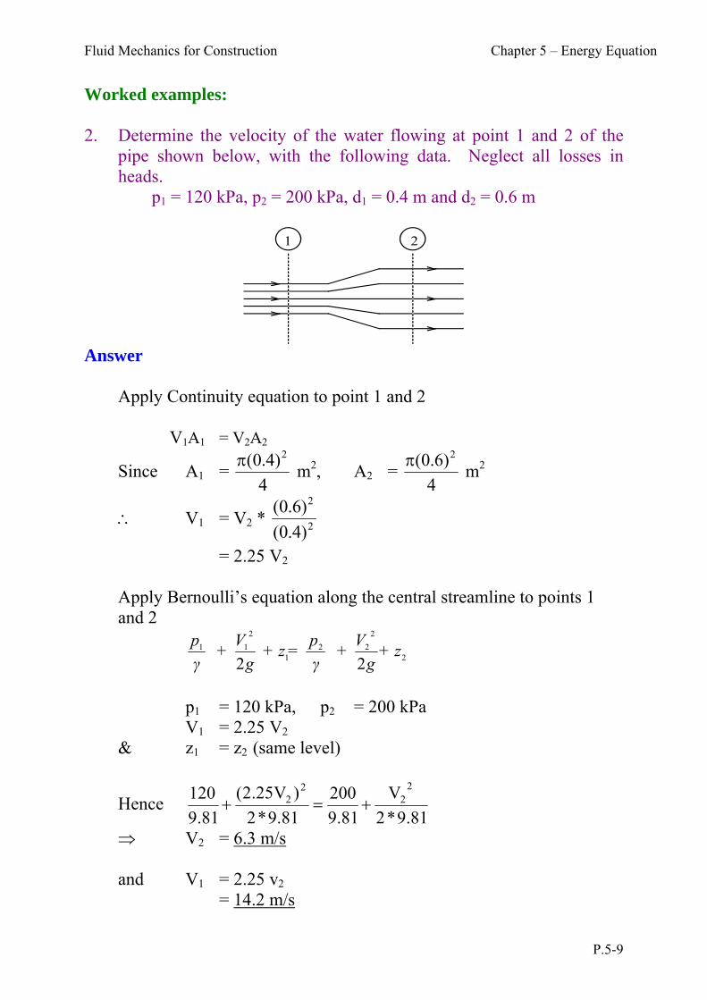
Worked examples: 2. Determine the velocity of the water flowing at point 1 and 2 of the
pipe shown below, with the following data. Neglect all losses in heads.
p1 = 120 kPa, p2 = 200 kPa, d1 = 0.4 m and d2 = 0.6 m
1 2
Answer Apply Continuity equation to point 1 and 2 V1A1 = V2A2
Since A1 = 4
)4.0( 2 m2, A2 =
4
)6.0( 2 m2
V1 = V2 * 2
2
)4.0(
)6.0(
= 2.25 V2
Apply Bernoulli’s equation along the central streamline to points 1 and 2
2
2
221
2
11
22+ z
g
V +
γ
p= + z
g
V +
γ
p
p1 = 120 kPa, p2 = 200 kPa V1 = 2.25 V2
& z1 = z2 (same level)
Hence 81.9*2
V
81.9
200
81.9*2
)V25.2(
81.9
120 22
22
V2 = 6.3 m/s and V1 = 2.25 v2 = 14.2 m/s
Fluid Mechanics for Construction Chapter 5 – Energy Equation
P.5-10
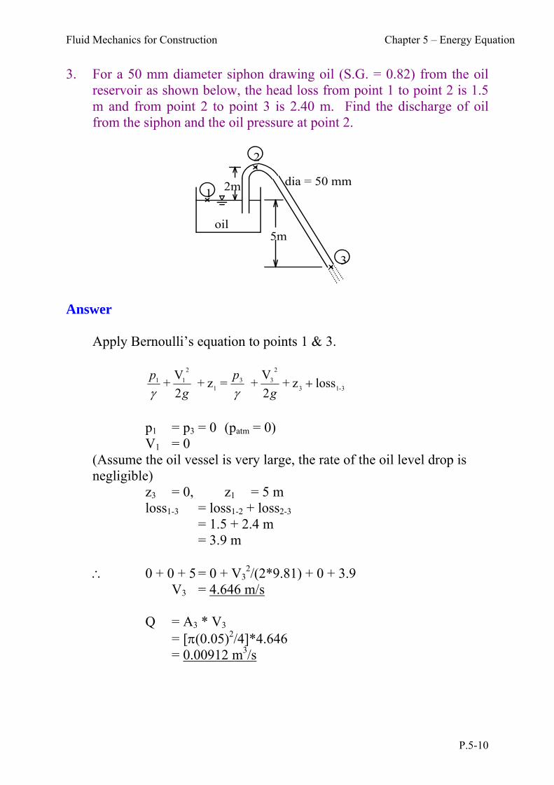
3. For a 50 mm diameter siphon drawing oil (S.G. = 0.82) from the oil reservoir as shown below, the head loss from point 1 to point 2 is 1.5 m and from point 2 to point 3 is 2.40 m. Find the discharge of oil from the siphon and the oil pressure at point 2.
1
2
3
2m
5moil
dia = 50 mm
Answer Apply Bernoulli’s equation to points 1 & 3.
3-13
2
331
2
11 loss z + 2
V + = z +
2
V +
g
p
g
p
p1 = p3 = 0 (patm = 0) V1 = 0
(Assume the oil vessel is very large, the rate of the oil level drop is negligible)
z3 = 0, z1 = 5 m loss1-3 = loss1-2 + loss2-3 = 1.5 + 2.4 m
= 3.9 m 0 + 0 + 5 = 0 + V3
2/(2*9.81) + 0 + 3.9 V3 = 4.646 m/s Q = A3 * V3 = [(0.05)2/4]*4.646 = 0.00912 m3/s
Fluid Mechanics for Construction Chapter 5 – Energy Equation
P.5-11
Again, apply Bernoulli’s equation to points 1 & 2
2
222
1
211 z +
g2
V +
p =z +
g2
V +
p
+ loss1-2
z2 = 7 m V2 = V3 (same pipe diameter) = 4.646 m loss1-2 = 1.5 m 0 + 0 + 5 = p2/ + (4.646)2/(2*9.81) + 7 + 1.5 p2/ = - 4.6 m p2 = - 4.6 * 9.81 * 0.82 kPa = - 36.9 kPa
Fluid Mechanics for Construction Chapter 5 – Energy Equation
P.5-12
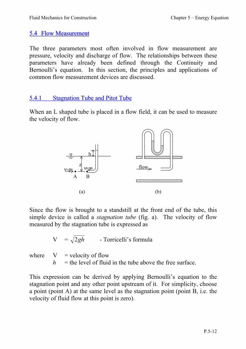
5.4 Flow Measurement The three parameters most often involved in flow measurement are pressure, velocity and discharge of flow. The relationships between these parameters have already been defined through the Continuity and Bernoulli’s equation. In this section, the principles and applications of common flow measurement devices are discussed. 55..44..11 SSttaaggnnaattiioonn TTuubbee aanndd PPiittoott TTuubbee When an L shaped tube is placed in a flow field, it can be used to measure the velocity of flow.
A B
h
zvA,pA vB,pB
(a)
flow
(b)
Since the flow is brought to a standstill at the front end of the tube, this simple device is called a stagnation tube (fig. a). The velocity of flow measured by the stagnation tube is expressed as V = gh2 - Torricelli’s formula
where V = velocity of flow h = the level of fluid in the tube above the free surface. This expression can be derived by applying Bernoulli’s equation to the stagnation point and any other point upstream of it. For simplicity, choose a point (point A) at the same level as the stagnation point (point B, i.e. the velocity of fluid flow at this point is zero).
Fluid Mechanics for Construction Chapter 5 – Energy Equation
P.5-13
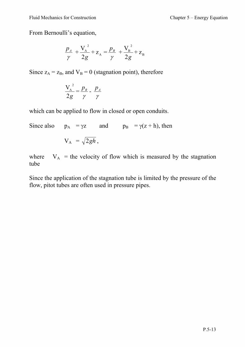
From Bernoulli’s equation,
B
2
BA
2
A z +2
V + =z +
2
V +
g
p
g
p BA
Since zA = zB, and VB = 0 (stagnation point), therefore
- = 2
V 2
A
AB pp
g
which can be applied to flow in closed or open conduits. Since also pA = z and pB = (z + h), then VA = gh2 ,
where VA = the velocity of flow which is measured by the stagnation tube Since the application of the stagnation tube is limited by the pressure of the flow, pitot tubes are often used in pressure pipes.

Fluid Mechanics for Construction Chapter 5 – Energy Equation
P.5-14
Worked examples: 4. Water flows through the pipe contraction shown in figure below. For
the given 0.2 m difference in manometer level, determine the flow rate when the diameter of the small pipe, D is 0.05m.
0.2 m
0.1 m(2)(1)
waterD
Q
h1h2
Answer Again, apply Bernoulli’s equation to points 1 & 2
2
2
221
2
11
22+ z
g
V +
γ
p= + z
g
V +
γ
p
V1 = 0 (stagnation point) z1 = z2 = 0 (same level)
02
V + = 0 +0 +
2
221 g
pp
V2 =
)(2 21 pp
g
but p1 = h1 and p2 = h2 p1 – p2 = (h1 – h2) = 0.2
Thus V2 = 2.0
*2g = 2.0*2g m/s
= 1.98 m/s Q = A2 * V2 = [(0.05)2/4]*1.98 = 3.888*10-3 m3/s = 3.888 L/s
Fluid Mechanics for Construction Chapter 5 – Energy Equation
P.5-15
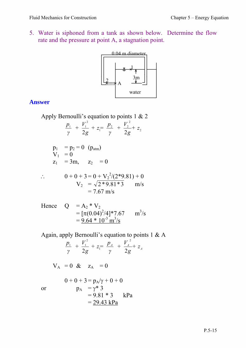
5. Water is siphoned from a tank as shown below. Determine the flow rate and the pressure at point A, a stagnation point.
1
A2
3m
0.04 m diameter
water
Answer
Apply Bernoulli’s equation to points 1 & 2
2
2
221
2
11
22+ z
g
V +
γ
p= + z
g
V +
γ
p
p1 = p2 = 0 (patm) V1 = 0 z1 = 3m, z2 = 0 0 + 0 + 3 = 0 + V2
2/(2*9.81) + 0 V2 = 3*81.9*2 m/s = 7.67 m/s
Hence Q = A2 * V2 = [(0.04)2/4]*7.67 m3/s = 9.64 * 10-3 m3/s
Again, apply Bernoulli’s equation to points 1 & A
AAA + zg
V +
γ
p= + z
g
V +
γ
p
22
2
1
2
11
VA = 0 & zA = 0 0 + 0 + 3 = pA/ + 0 + 0 or pA = * 3 = 9.81 * 3 kPa = 29.43 kPa

Fluid Mechanics for Construction Chapter 5 – Energy Equation
P.5-16
55..44..22 SSmmaallll OOrriiffiiccee An orifice is a geometric opening in the side of a wall and tank, through which fluid can flow. A circular sharp edged orifice at the side of a water tank is shown. It is assumed that the size of orifice area, A is small compared with the depth of water, H.
A
BvB
vA H
Orifice area, A
The volume rate of flow discharged through an orifice will depend upon the head of the fluid above the level of the orifice and it can therefore be used as a means of flow measurement. Applying Bernoulli’s equation to A and B, assuming that there is no loss of energy,
+ zg
V +
γ
p = + z
g
V +
γ
pB
BBA
AA
22
22
Putting zA - zB = H, VA = 0, VB = V and pA = pB, velocity of jet, V = gH2
Theoretically, if A is the cross-sectional area of the orifice, Discharge, Q = Area * Velocity = A gH2
In practice, the actual discharge is considerably less than the theoretical discharge and is modified by introducing a coefficient of discharge, Cd, so that Actual discharge, Qactual = Cd * Qtheoretical = CdA gH2
Fluid Mechanics for Construction Chapter 5 – Energy Equation
P.5-17
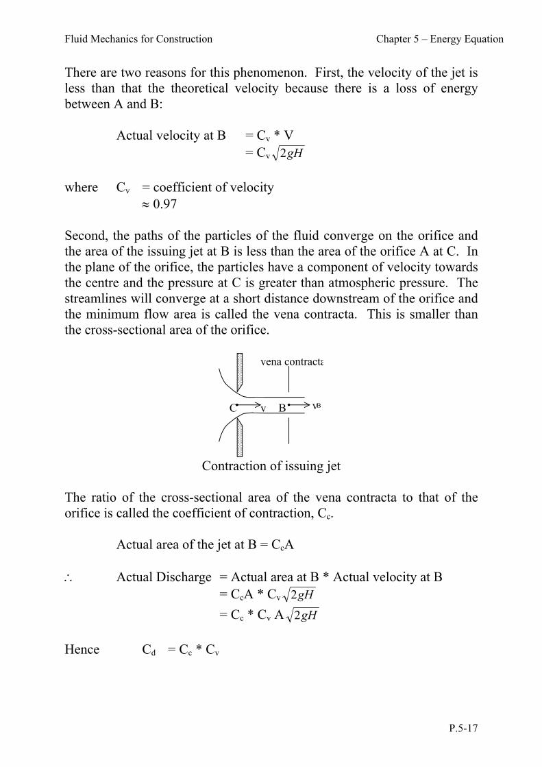
There are two reasons for this phenomenon. First, the velocity of the jet is less than that the theoretical velocity because there is a loss of energy between A and B: Actual velocity at B = Cv * V = Cv gH2
where Cv = coefficient of velocity 0.97 Second, the paths of the particles of the fluid converge on the orifice and the area of the issuing jet at B is less than the area of the orifice A at C. In the plane of the orifice, the particles have a component of velocity towards the centre and the pressure at C is greater than atmospheric pressure. The streamlines will converge at a short distance downstream of the orifice and the minimum flow area is called the vena contracta. This is smaller than the cross-sectional area of the orifice.
C Bv vB
vena contracta
Contraction of issuing jet
The ratio of the cross-sectional area of the vena contracta to that of the orifice is called the coefficient of contraction, Cc. Actual area of the jet at B = CcA Actual Discharge = Actual area at B * Actual velocity at B = CcA * Cv gH2
= Cc * Cv A gH2
Hence Cd = Cc * Cv
Fluid Mechanics for Construction Chapter 5 – Energy Equation
P.5-18
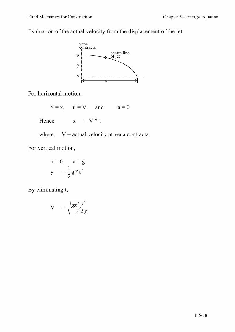
Evaluation of the actual velocity from the displacement of the jet
For horizontal motion, S = x, u = V, and a = 0 Hence x = V * t where V = actual velocity at vena contracta For vertical motion, u = 0, a = g
y = 2t*g2
1
By eliminating t,
V = ygx
2
2
y
x
venacontracta
centre lineof jet

Fluid Mechanics for Construction Chapter 5 – Energy Equation
P.5-19
Worked examples: 6. Oil of specific gravity 0.82 discharges from an open tank through an
orifice of diameter 14 mm. The coefficient of velocity is 0.88 and the coefficient of contraction is 0.62. The centre of the orifice is at a depth of 0.9m from the surface of the oil. Determine the diameter of the vena contracta and the discharge of oil through the orifice.
Answer
0.9m orifice holedia = 14mm
A = * (14/1000)2/4 = 1.54 * 10-4 m2 Since Cc = Ac/A 0.62 = Ac / 1.54 * 10-4 hence Ac = 0.955 * 10-4 m2 or dc = 0.01102 m = 11.02 mm Theoretical velocity, V = gh2
= 2 9 81 0 9* . * . = 4.0202 m/s Theoretical discharge, Q = V*A = 4.02 * 1.54 * 10-4 = 6.47 * 10-4 m3/s Coefficient of discharge, Cd = Cv * Cc = 0.88 * 0.62 = 0.546 Actual discharge = Cd * Theoretical discharge = 0.546 * 6.47 * 10-4 = 3.53 * 10-4 m3/s = 0.353 L/s
Fluid Mechanics for Construction Chapter 5 – Energy Equation
P.5-20
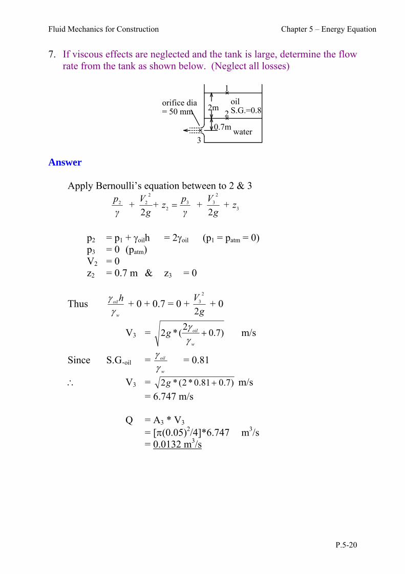
7. If viscous effects are neglected and the tank is large, determine the flow rate from the tank as shown below. (Neglect all losses)
1
2
3
2m
0.7m
oilS.G.=0.81
water
orifice dia= 50 mm
Answer
Apply Bernoulli’s equation between to 2 & 3
3
2
332
2
22
22 + z
g
V +
γ
p+ z
g
V +
γ
p
p2 = p1 + oilh = 2oil (p1 = patm = 0) p3 = 0 (patm)
V2 = 0 z2 = 0.7 m & z3 = 0
Thus w
oilh
+ 0 + 0.7 = 0 + g
V
2
2
3 + 0
V3 = )7.02
(*2 w
oilg
m/s
Since S.G.oil = w
oil
= 0.81
V3 = )7.081.0*2(*2 g m/s
= 6.747 m/s
Q = A3 * V3 = [(0.05)2/4]*6.747 m3/s = 0.0132 m3/s

Fluid Mechanics for Construction Chapter 5 – Energy Equation
P.5-21
55..44..33 VVeennttuurrii MMeetteerr The venturi meter is the most commonly used device for flow measurement and is designed with a streamlined throat which can, 1. reduce the overall head loss, and 2. reduce the normal mechanical wear of the device. The discharge
equation for a venturi meter is the same as for an orifice meter, except that the flow coefficient value of a venturi meter is generally higher than that of an orifice meter and a flow nozzle. This follows since the coefficient of contraction of a venturi meter is unity.
entry
convergingcone
throatdiverging section
h
1 2
Consider the pressure difference between point 1 & 2 as measured by the U-tube manometer. hPP m )(21 By continuity equation, V1A1 = V2A2
or 1
2
12 V
A
AV
Applying Bernoulli’s equation between point 1 & 2,
2
2
221
2
11
22+ z
g
V +
γ
p= + z
g
V +
γ
p
z1 = z2
hence g
V )
A
A = (
g
V +
γ
γ)h(γm
22
2
12
2
1
2
1
Fluid Mechanics for Construction Chapter 5 – Energy Equation
P.5-22
V1 = 1)(
)1(2
2
2
1
AA
gh m
Hence discharge Q = A1V1
= )1(2
1)( 2
2
1
1
mgh
AA
A
Actual discharge = CdQ
= )1(2
1)( 2
2
1
1
md gh
AA
AC
Fluid Mechanics for Construction Chapter 5 – Energy Equation
P.5-23
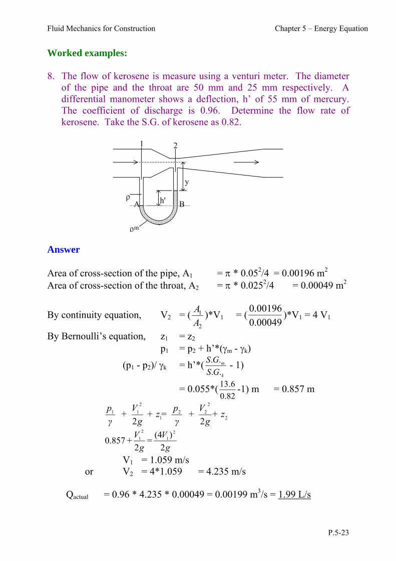
Worked examples: 8. The flow of kerosene is measure using a venturi meter. The diameter
of the pipe and the throat are 50 mm and 25 mm respectively. A differential manometer shows a deflection, h’ of 55 mm of mercury. The coefficient of discharge is 0.96. Determine the flow rate of kerosene. Take the S.G. of kerosene as 0.82.
h'
1 2
A B
y
m Answer Area of cross-section of the pipe, A1 = * 0.052/4 = 0.00196 m2 Area of cross-section of the throat, A2 = * 0.0252/4 = 0.00049 m2
By continuity equation, V2 = (2
1
A
A)*V1 = (
00049.0
00196.0)*V1 = 4 V1
By Bernoulli’s equation, z1 = z2 p1 = p2 + h’*(m - k)
(p1 - p2)/ k = h’*(k
m
GS
GS
..
.. - 1)
= 0.055*(82.0
6.13 -1) m = 0.857 m
2
2
221
2
11
22+ z
g
V +
γ
p= + z
g
V +
γ
p
g
V
g
V
2
)(4 =
2 + .8570
2
1
2
1
V1 = 1.059 m/s or V2 = 4*1.059 = 4.235 m/s Qactual = 0.96 * 4.235 * 0.00049 = 0.00199 m3/s = 1.99 L/s

Fluid Mechanics for Construction Chapter 5 – Energy Equation
P.5-24
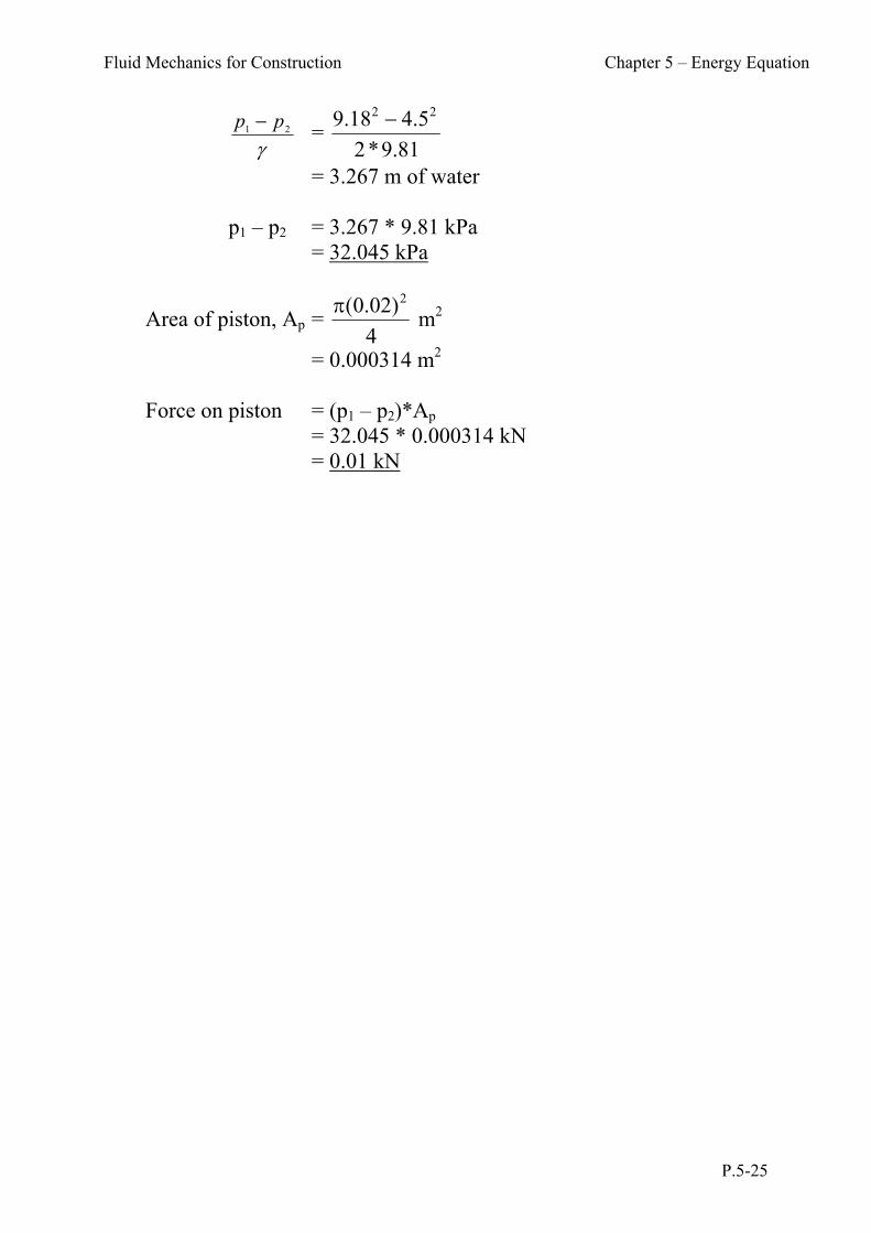
9. The water supply to a gas water heater contracts from 10 mm in diameter at 1 to 7 mm in diameter at 2 (figure below). If the pipe is horizontal, calculate the difference in pressure between 1 and 2 when the velocity of the water at 1 is 4.5 m/s. The pressure difference operates the gas control through connections which are taken to horizontal cylinder in which a piston of 20 mm diameter moves. Ignoring friction and the area of the piston connecting rod, what is the force on the piston?
1 2
Answer
For Continuity of flow, V1A1 = V2A2
Since A1 = 4
π(0.01) 2
m2, A2 = 4
π(0.007)2
m2
V1 = 4.5 m/s
V2 = 4.5 * 2
2
(0.007)
(0.01) m/s
= 9.18 m/s
Apply Bernoulli’s equation to points 1 & 2
2
2
221
2
11
22+ z
g
V +
γ
p= + z
g
V +
γ
p
z1 = z2 (same level) V1 = 4.5 m/s V2 = 9.18 m/s
hence 081.9*2
18.9 + = 0
81.9*2
5.4 +
22
21
pp
Fluid Mechanics for Construction Chapter 5 – Energy Equation
P.5-25
21 pp =
81.9*2
5.418.9 22
= 3.267 m of water p1 – p2 = 3.267 * 9.81 kPa = 32.045 kPa
Area of piston, Ap = 4
)02.0( 2 m2
= 0.000314 m2 Force on piston = (p1 – p2)*Ap = 32.045 * 0.000314 kN = 0.01 kN

Fluid Mechanics for Construction Chapter 5 – Energy Equation
P.5-26
10. Air flows through the device shown below. If the flow rate is large enough, the pressure within the construction will be low enough to draw the water up into the tube. Determine the flow rate, Q and the pressure needed at section 1 to draw the water into section 2. Neglect compressibility and viscous effects.
12 3air
water
dia = 50 mm dia = 50 mm
dia = 25 mm
0.3m
free jet
Answer
For Continuity of flow, V2A2 = V3A3
V2 = V3 * 2
2
2
3
)(
)(
d
d
= V3 * 2
2
)25(
)50(
= 4V3
Apply Bernoulli’s equation between to 2 & 3
3
2
332
2
22
22 + z
g
V +
γ
p+ z
g
V +
γ
p
p3 = 0 z2 = z3 (same level) p2 = -wh
air
p
2 = - h
air
w
= - 3.0*12
1000*81.9 m
= - 245.25 m
Fluid Mechanics for Construction Chapter 5 – Energy Equation
P.5-27
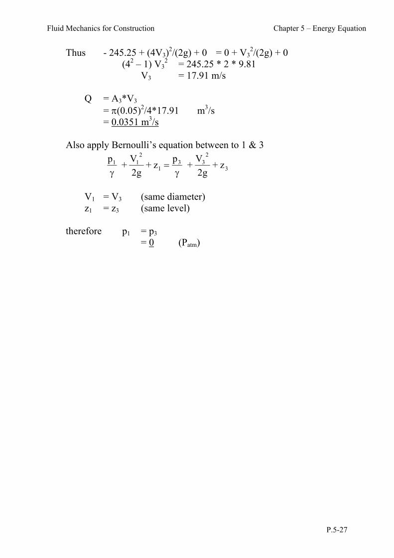
Thus - 245.25 + (4V3)2/(2g) + 0 = 0 + V3
2/(2g) + 0 (42 – 1) V3
2 = 245.25 * 2 * 9.81 V3 = 17.91 m/s Q = A3*V3 = (0.05)2/4*17.91 m3/s = 0.0351 m3/s
Also apply Bernoulli’s equation between to 1 & 3
3
233
1
211 z +
g2
V +
pz +
g2
V +
p
V1 = V3 (same diameter) z1 = z3 (same level) therefore p1 = p3 = 0 (Patm)
Fluid Mechanics for Construction Chapter 5 – Energy Equation
P.5-28
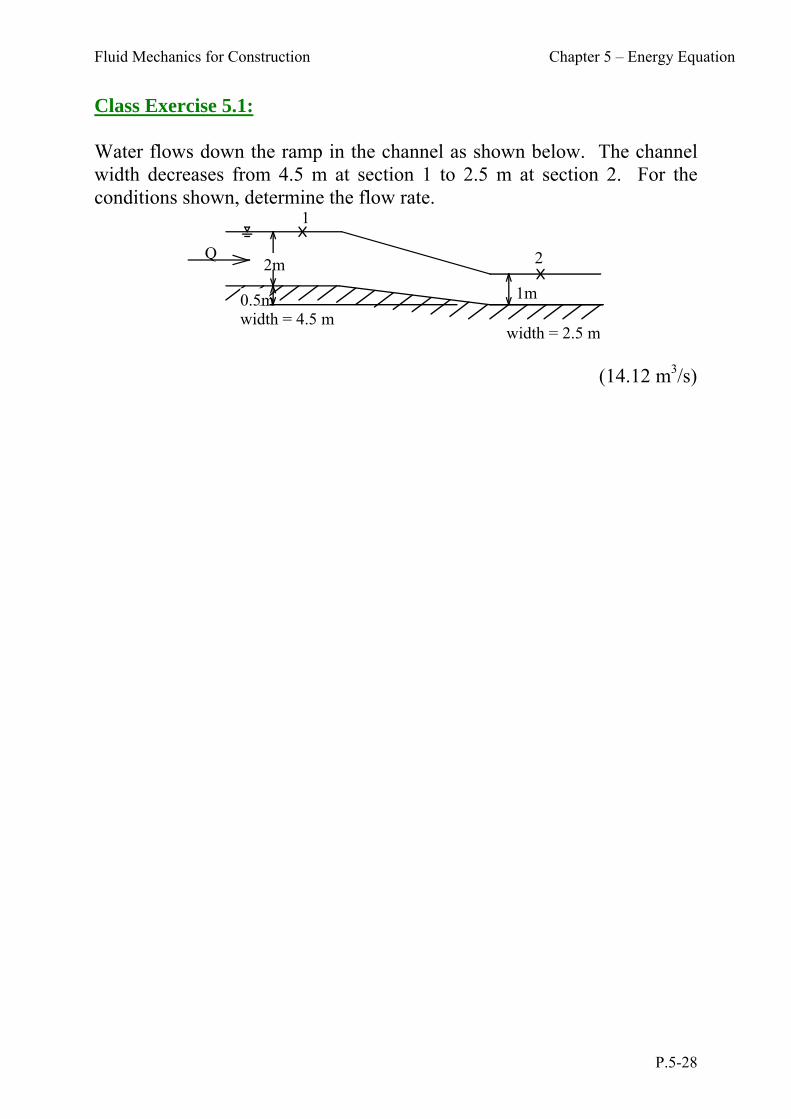
Class Exercise 5.1: Water flows down the ramp in the channel as shown below. The channel width decreases from 4.5 m at section 1 to 2.5 m at section 2. For the conditions shown, determine the flow rate.
1
2Q2m
0.5m 1m
width = 4.5 mwidth = 2.5 m
(14.12 m3/s)
Fluid Mechanics for Construction Chapter 5 – Energy Equation
P.5-29
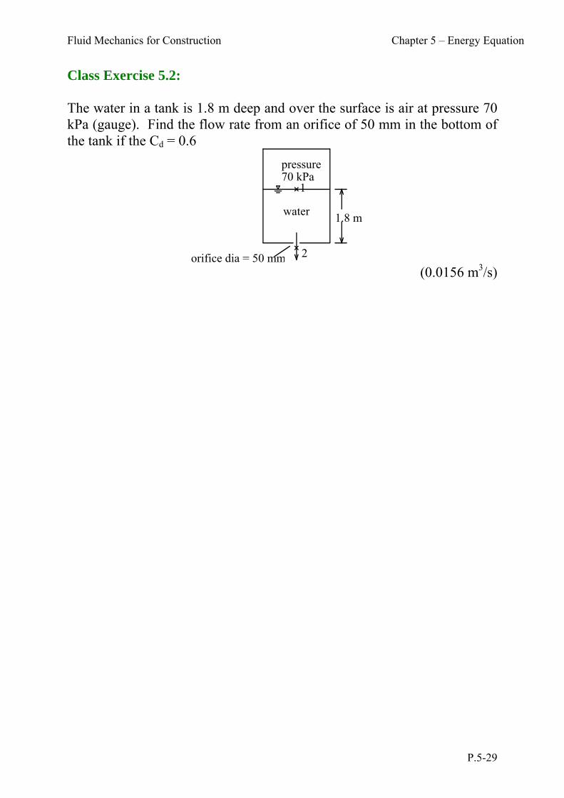
Class Exercise 5.2: The water in a tank is 1.8 m deep and over the surface is air at pressure 70 kPa (gauge). Find the flow rate from an orifice of 50 mm in the bottom of the tank if the Cd = 0.6
pressure70 kPa
water1.8 m
orifice dia = 50 mm
1
2 (0.0156 m3/s)
Fluid Mechanics for Construction Chapter 5 – Energy Equation
P.5-30
Class Exercise 5.3: A horizontal venturi tube, 280 mm diameter at the entrance and 140 mm diameter at the throat, has a discharge coefficient of 0.97. A U-tube manometer filled with mercury is connected between the entrance and the throat to measure the water flow between them. Calculate the flowrate when the difference in the mercury level is 50 mm. (0.0542 m3/s)
Fluid Mechanics for Construction Chapter 5 – Energy Equation
P.5-31
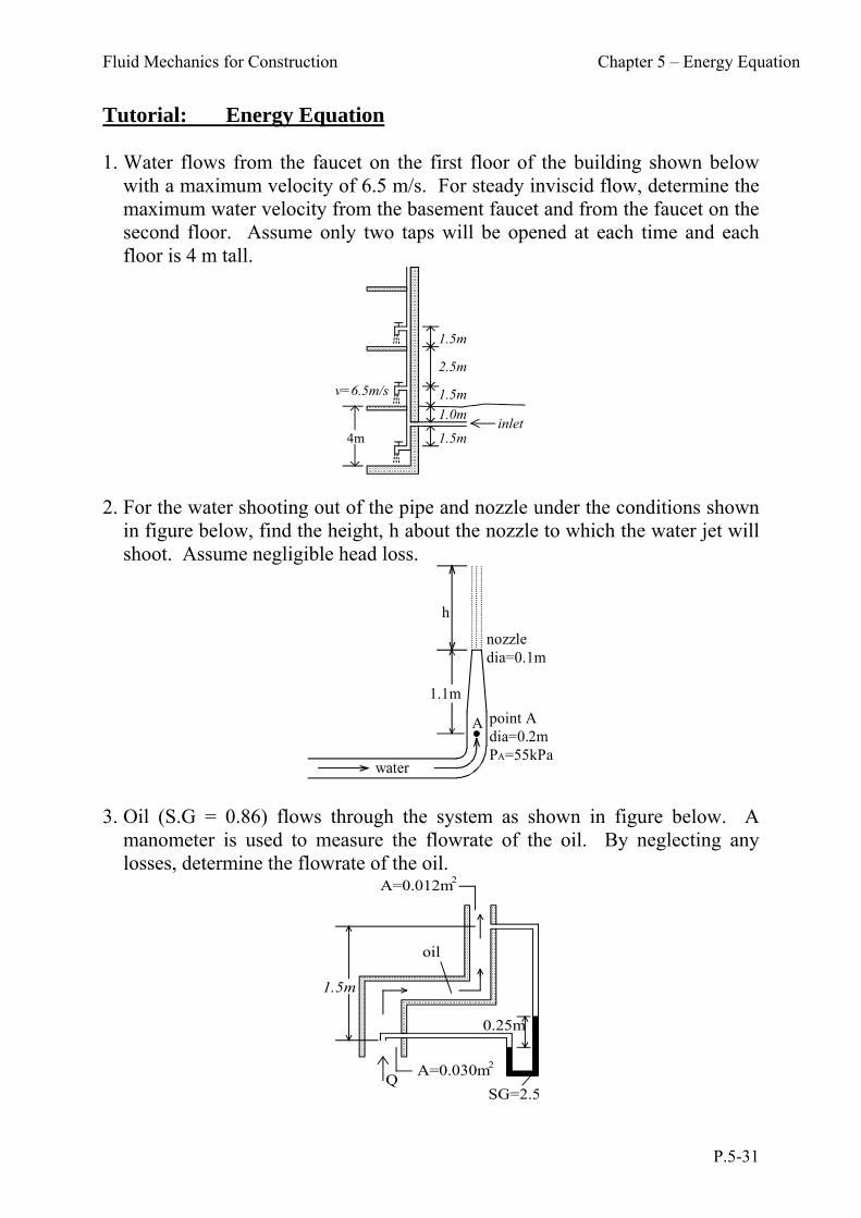
Tutorial: Energy Equation 1. Water flows from the faucet on the first floor of the building shown below
with a maximum velocity of 6.5 m/s. For steady inviscid flow, determine the maximum water velocity from the basement faucet and from the faucet on the second floor. Assume only two taps will be opened at each time and each floor is 4 m tall.
1.5m
2.5m
1.5m
4m
1.0m
1.5minlet
v=6.5m/s
2. For the water shooting out of the pipe and nozzle under the conditions shown
in figure below, find the height, h about the nozzle to which the water jet will shoot. Assume negligible head loss.
h
1.1m
nozzledia=0.1m
A point Adia=0.2mPA=55kPa
water 3. Oil (S.G = 0.86) flows through the system as shown in figure below. A
manometer is used to measure the flowrate of the oil. By neglecting any losses, determine the flowrate of the oil.
Q
0.25m
1.5m
SG=2.5
oil
A=0.012m2
A=0.030m2
Fluid Mechanics for Construction Chapter 5 – Energy Equation
P.5-32
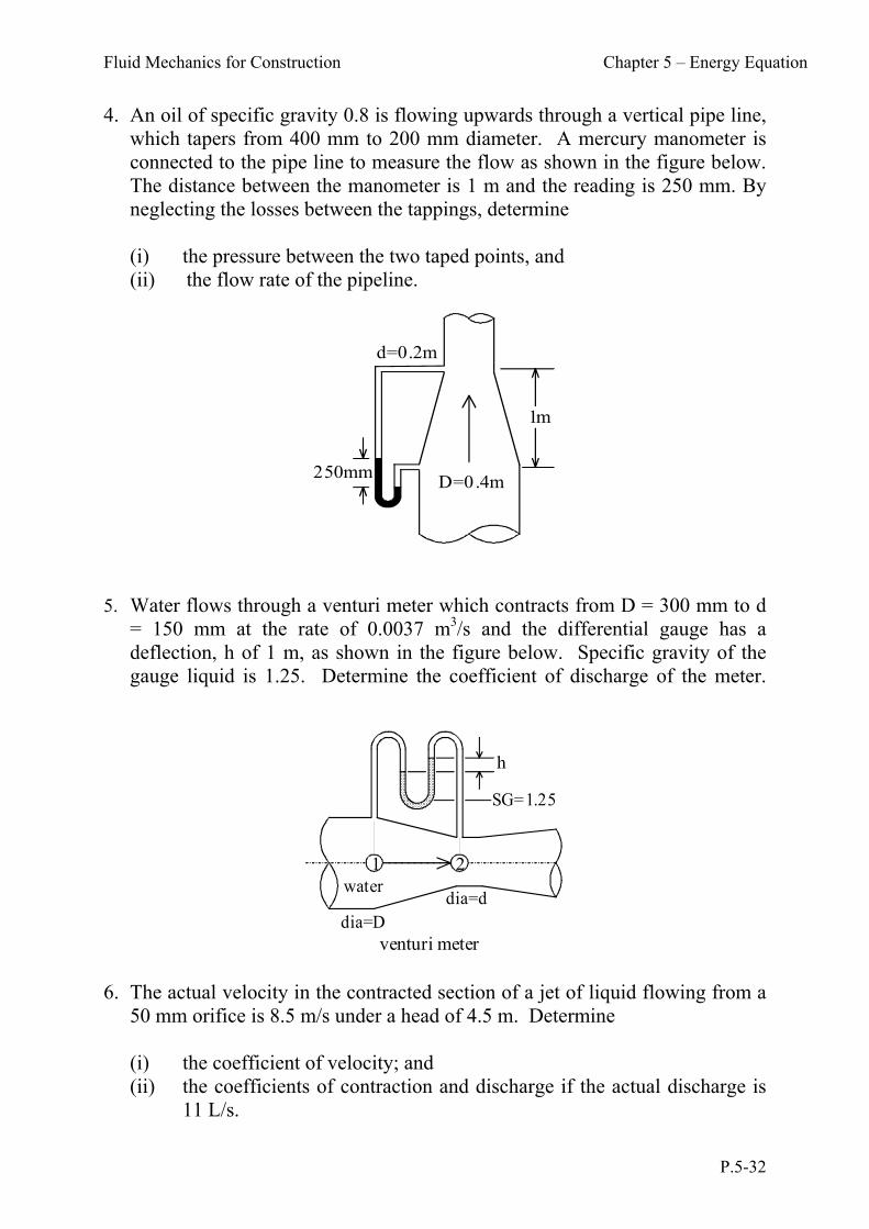
4. An oil of specific gravity 0.8 is flowing upwards through a vertical pipe line, which tapers from 400 mm to 200 mm diameter. A mercury manometer is connected to the pipe line to measure the flow as shown in the figure below. The distance between the manometer is 1 m and the reading is 250 mm. By neglecting the losses between the tappings, determine
(i) the pressure between the two taped points, and (ii) the flow rate of the pipeline.
D=0.4m
d=0.2m
250mm
1m
5. Water flows through a venturi meter which contracts from D = 300 mm to d
= 150 mm at the rate of 0.0037 m3/s and the differential gauge has a deflection, h of 1 m, as shown in the figure below. Specific gravity of the gauge liquid is 1.25. Determine the coefficient of discharge of the meter.
1 2
h
venturi meter
waterdia=d
SG=1.25
dia=D
6. The actual velocity in the contracted section of a jet of liquid flowing from a
50 mm orifice is 8.5 m/s under a head of 4.5 m. Determine (i) the coefficient of velocity; and (ii) the coefficients of contraction and discharge if the actual discharge is
11 L/s.

Fluid Mechanics for Construction Chapter 5 – Energy Equation
P.5-33
7. Oil flows through a standard 25 mm diameter orifice under 5.5 m head at a measured rate of 3 L/s. The jet strikes a wall 1.5 m away and 0.12 m vertically below the centreline of the contracted section of the jet. Determine all the coefficients of the orifice.
8. A pitot tube is used to measure the air flow rate of a pipe as shown in the
figure below. Determine the velocity and hence the flow rate of the oil in the tube. The S.G. of the manometer liquid is 0.827 and density of air is 1.2 kg/m3.
END