Embed Size (px)
Citation preview
---------------------------------------------------------------------------------------------------------------------
1.0 INTRODUCTION
In the physical processing stage of material recovery from end-of-life printed circuit boards (eol
PCB), metallic and non-metallic values on the boards are separated into different materials
fractions through a series of stage-wise comminution-separations. Various separation
technologies are employed in processing the diverse mixture of materials that the comminution
operations produce at different stages. These include magnetic separation, eddy current
separation, electrostatic separation, air tables, gravity air classifiers, air cyclones and shape
screens, among others (Goosey and Kellner, 2003; Li et al., 2004; Kang and Schoenung, 2005;
Hamos GmbH).
As expected, each separation operation gives optimum efficiencies at specific size ranges. At
smaller sizes, below 2mm, electrostatic separation has been mostly applied for copper recovery
from the grinding mix (Zhang and Forssberg, 1997; Iuga et al., 1998; Li et al, 2004, Hamos
GmbH; Kang and Schoenung, 2005). From classical mineral processing, application of
electrostatic separation is known to give poor separation efficiencies at −100 µm fine sizes
(Wills, 1997). Zhao et al. (2004) demonstrated the application of a type of column air separator
compared to an electrostatic separator. For the −75 µm fractions, copper recoveries of 27.83 % at
a grade of 26.8 % were obtained from the pneumatic separator while separation from the
electrostatics at that size was declared poor and not reported. The low recovery implies valuable
metal loss at this size range, while such poor grade implies product contamination, thereby
complicating the finishing recovery processes. Overall improvement to the physical processing
stage, in order to produce cleaner fractions, has been emphasized (Goosey and Kellner, 2003).
In the cited instance (Zhao et al., 2004), more than 20 % of the product of the hammer mill
grinding from 30 mm feed top size reported to the -75 µm fraction, assaying almost 2.9 %
copper. Less than half copper recovery from this fraction implies that more than 0.29 % of the
total grinding product by weight, ~2.9 kg/ton of copper, will be lost. In NEC corporation
recycling operation, at -300 + 100 µm (Yokoyama and Iji, 1997; Iji and Yokoyama, 1997),
----------------------------------------------------------------------------------------Chapter 1: Introduction
--------------------------------------------------------------------------------------------------------------- 2
copper rich powder (82%Cu, at >90% recovery) was produced from the electrostatic separation,
with the non-conducting fraction containing 64 % glass fibre, 34 % epoxy resin, 2.1 % Cu, and
solders. Some end-use applications, such as filler for epoxy resin polymer products, were
investigated for the glass fibre-resin fraction. However, at 2.1 % copper content, the fibre glass-
resin non-conducting fraction assays higher than many natural porphyry copper deposits that are
being mined and economically processed (Wills, 1997). It therefore deserves further
beneficiation. Moreover, as precious metals are coated to a few microns in the printed circuit
board (PCB) sockets and slots, and on the edge connectors, abrasion in the event of comminution
is likely to make this precious metal report to this fine fraction also. With the poor separation
efficiencies of electrostatic separation at -100 µm, these precious metal fraction will mostly
report to the non-conducting fraction (Kelly and Spottiswood, 1989), representing a major loss to
the economic drive of the whole operation. Traces of noble metal anti-etch materials used during
the printed copper circuit production (Li et al., 2004) should also be present on the copper traces;
copper particles not recovered carry such to waste. All these underscore the point that the fine
fraction from PCB grinding presents the challenges of low separation efficiency and
contamination of product fractions, while contributing a drop to the overall physical processing
recovery relative to coarser size fractions.
The inefficiency of electrostatic separation in processing the fine fraction has been tolerated by
recycling operations, possibly because of preference for keeping the operations dry. Wet
processes are avoided in most recycling operations, to avoid wash water circuit and treatment
costs, among other reasons (Kellerwessel, 1993). Given the diverse material make-up of printed
circuit boards (PCB), chances of hazardous leaching during wet processing may also be
contemplated. However, at this stage of PCB physical processing, the operation need not be
restricted to dry. Wet processing, and especially froth flotation, appears very promising. Success
in this direction can be a pointer to improved processing approach and overall improvement in
PCB physical processing. Density-based applications for wet table and centrifugal separations
have been reported (Galbraith and Devereux, 2002; Xuefeng et al., 2005). Froth flotation
exploits distinct surface property of individual particles and it appears very promising for
detailed investigation, more so that there has not been any effort to conduct empirical research
into its applicability. Froth flotation is well explored in minerals and, to some extent, in waste
processing. Outstanding features of froth flotation are its selectivity, flexibility, throughput and
----------------------------------------------------------------------------------------Chapter 1: Introduction
--------------------------------------------------------------------------------------------------------------- 3
handling of relatively fine sizes. These make it very relevant to this application. Froth flotation
has been used for beneficiation of ore bearing native metals and oxides minerals, among others.
Flotation of plastics has also been applied in municipal solid waste treatment (Shent et al., 1999;
Alter, 2005). PCB fines consist of a mixture of metals, alloys, ceramics and plastics with distinct
surface properties that should enable selective wetting and make froth flotation separation
possible. This is a broad hypothesis upon which froth flotation can be expected to be applicable
for the beneficiation of this material mixture. However, if co-occurrence of three minerals such
as chalcopyrite, pyrite and galena is recognised as complex in conventional minerals processing
(Wills, 1997), then this sample is really complex. It will present an interesting challenge to the
versatility of flotation technique.
The general objective of this research is, therefore, to investigate froth flotation for beneficiation
of this material mixture, with the aim of being able to conclude on the applicability. In this
connection, characterisation relevant to flotation investigation of the sample will first have to be
done. From the peculiarities of the sample based on the characterisation, along with general
literature survey, and with pointers from trial investigations, logical flotation schemes will be
drawn for the investigations. Toward these ends, a general background literature review is first
presented. This is followed by a more focused literature-based discourse aimed at drawing the
flotation schemes, and at stating more specific objectives, and approaches to, the investigation.
---------------------------------------------------------------------------------------------------------------------
2.0 BACKGROUND – PCB PHYSICAL PROCESSING
2.1 INTRODUCTION
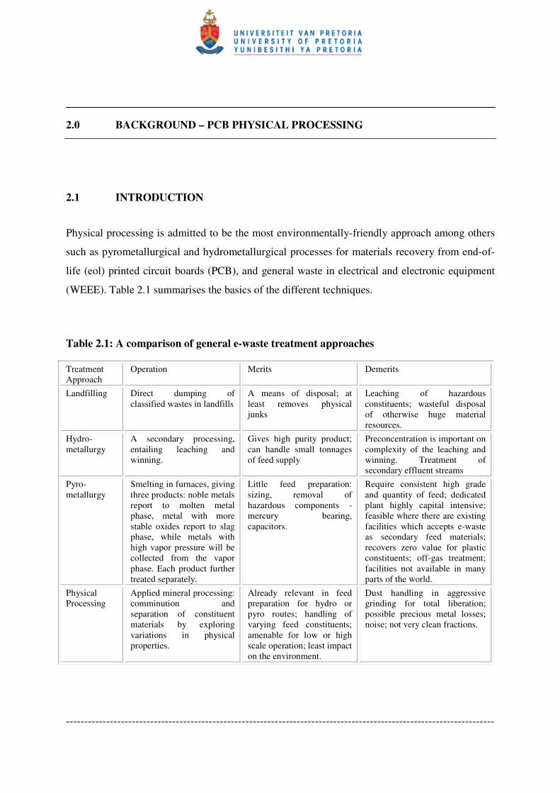
Physical processing is admitted to be the most environmentally-friendly approach among others
such as pyrometallurgical and hydrometallurgical processes for materials recovery from end-of-
life (eol) printed circuit boards (PCB), and general waste in electrical and electronic equipment
(WEEE). Table 2.1 summarises the basics of the different techniques.
Table 2.1: A comparison of general e-waste treatment approaches
Treatment
Approach
Operation Merits Demerits
Landfilling Direct dumping of
classified wastes in landfills
A means of disposal; at
least removes physical
junks
Leaching of hazardous
constituents; wasteful disposal
of otherwise huge material
resources.
Hydro-
metallurgy
A secondary processing,
entailing leaching and
winning.
Gives high purity product;
can handle small tonnages
of feed supply
Preconcentration is important on
complexity of the leaching and
winning. Treatment of
secondary effluent streams
Pyro-
metallurgy
Smelting in furnaces, giving
three products: noble metals
report to molten metal
phase, metal with more
stable oxides report to slag
phase, while metals with
high vapor pressure will be
collected from the vapor
phase. Each product further
treated separately.
Little feed preparation:
sizing, removal of
hazardous components -
mercury bearing,
capacitors.
Require consistent high grade
and quantity of feed; dedicated
plant highly capital intensive;
feasible where there are existing
facilities which accepts e-waste
as secondary feed materials;
recovers zero value for plastic
constituents; off-gas treatment;
facilities not available in many
parts of the world.
Physical
Processing
Applied mineral processing:
comminution and
separation of constituent
materials by exploring
variations in physical
properties.
Already relevant in feed
preparation for hydro or
pyro routes; handling of
varying feed constituents;
amenable for low or high
scale operation; least impact
on the environment.
Dust handling in aggressive
grinding for total liberation;
possible precious metal losses;
noise; not very clean fractions.
-------------------------------------------------------Chapter 2: Background: PCB Physical Processing
-------------------------------------------------------------------------------------------------------------- 5
Major demerits of the physical processing option include product fractions that remain largely
unsorted to have best end-values as separate material fractions (Lee et al., 2004). This makes
pyrometallurgical follow-up processing indispensable and extensive (Lee et al., 2004; Shuey, et
al., 2006). This points to the need for cleaner fractions from the physical processing stage.
A background review of PCB physical processing will help to place the various aspects of the
operation into perspective. A characterisation to appraise the huge material resource and the
diversity in the material stream will be informative. This is followed by a review of the physical
processing operations in almost three decade of this endeavor. This will clarify how
improvement in the beneficiation of the comminution fines can contribute to improving the
operation.
2.2 PCB CHARACTERISATION
2.2.1 Occurrence and Reserve
Printed circuit board (PCBs) mechanically support and electrically connect electronic
components by using conductive pathways, or traces, etched from copper sheets laminated onto a
non-conductive substrate (Wikipedia). Alternative names are printed wiring board (PWB),
etched wiring board (EWB). Populated PCBs have mounted components, while unpopulated
ones comprise of only reinforced resin and printed copper wiring laminate. PCBs are found in
almost all electronic applications, spanning personal computers, telecommunication equipment,
hospital equipment, cellphones and various consumer electronics. Continuing and rapid advances
in technological innovations result in a high rate of obsolescence of this equipment, leading to
large tonnages of PCB going into the WEEE stream.
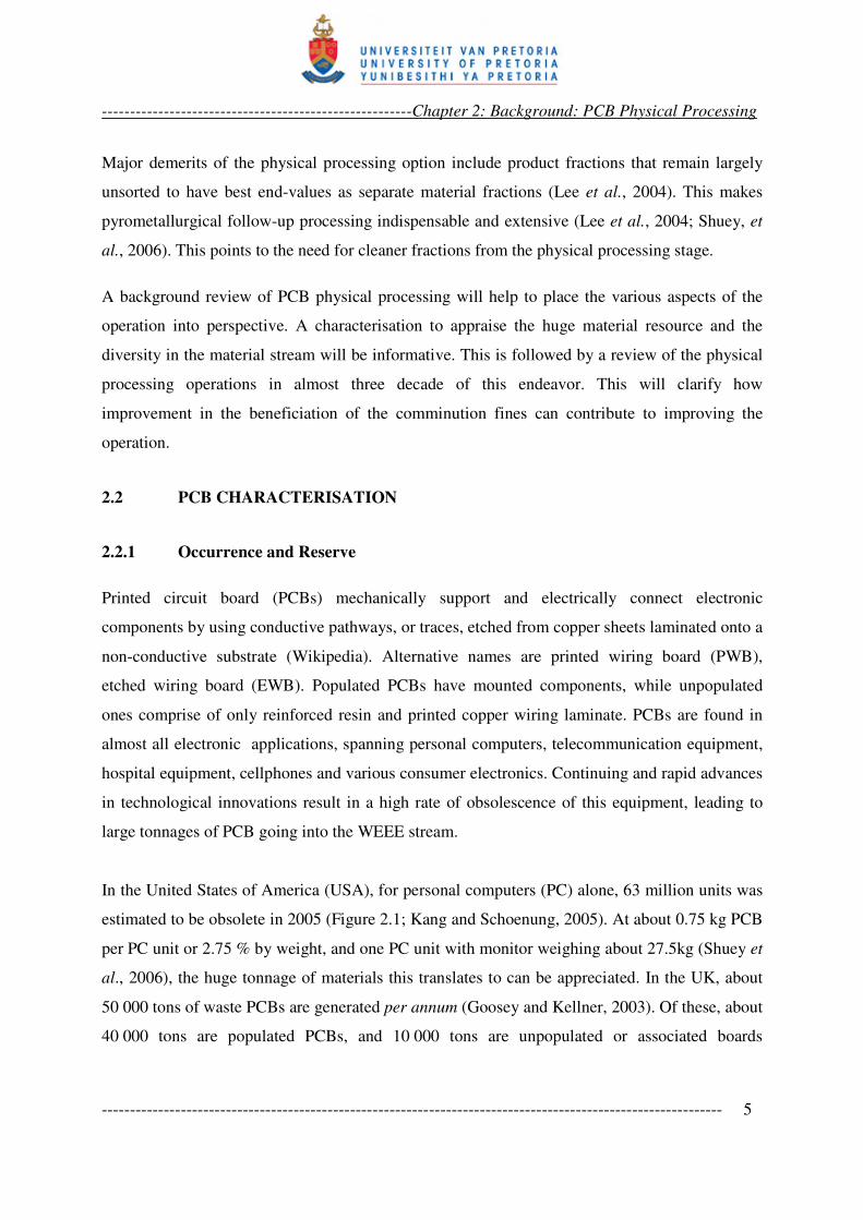
In the United States of America (USA), for personal computers (PC) alone, 63 million units was
estimated to be obsolete in 2005 (Figure 2.1; Kang and Schoenung, 2005). At about 0.75 kg PCB
per PC unit or 2.75 % by weight, and one PC unit with monitor weighing about 27.5kg (Shuey et
al., 2006), the huge tonnage of materials this translates to can be appreciated. In the UK, about
50 000 tons of waste PCBs are generated per annum (Goosey and Kellner, 2003). Of these, about
40 000 tons are populated PCBs, and 10 000 tons are unpopulated or associated boards
-------------------------------------------------------Chapter 2: Background: PCB Physical Processing
-------------------------------------------------------------------------------------------------------------- 6
manufacturing scrap. The estimate for 2006 is 100500 tons (Shuey et al., 2006). A year 2000
review in Taiwan claims about 300 000 scrap PC units per annum (Lee et al., 2000), and this had
risen to 700 000 by 2004 (Lee et al., 2004). With generally few statistics for South Africa, more
than 500 000 PC units are reported dumped per year. Intel South Africa, an original equipment
manufacturer (OEM), has been in business for 35 years and has sold more than one billion CPUs.
This implies a lot of PCs out somewhere (Mackay, 2004). Large undocumented accumulation, or
scatters, of PCBs occur around the world, much due to shipment of used PC to developing
countries. A 2005 British Broadcasting Corporation (BBC) report, focused on Nigeria, claimed
that about 400 000 used computers are imported to Nigeria monthly. Almost 75 % of these
cannot be used, cannot be repaired economically or resold. The situation is typical of many
developing countries (Laurie, 2005).
Figure 2.1: Personal computer shipments and obsolescence in the United States (Kang and
Schoenung, 2005)
Taking PCBs as a highly valuable polymetallic resource, the foregoing has been an attempt to
present its occurrence and ‘reserve’. Recognizing the material values it contains (see Section
2.2.3), eol PCB stream can be referred to as a type of ore, rather than a waste stream. Though not
containing specific minerals with definite chemical composition, according to the classical
-------------------------------------------------------Chapter 2: Background: PCB Physical Processing
-------------------------------------------------------------------------------------------------------------- 7
definition of an ore, the stream contains many of the metallic elements in the periodic table, in
proportions greater than many natural deposits of such metals. It therefore deserves better
recognition as a resource stock. PCB processing yields concentrates that feed into metal
production, just like run-of-mines. On this basis, PCBs and other end-of-life electronic
equipment can regarded as a type ore – industrial ores (Castro et al., 2005). This distinguishes
PCBs from natural ore from the mine, because this material stream is from the industry after a
service life. In the broad view of cyclic material use, WEEE is essentially a transit title.
2.2.2 PCB Structure
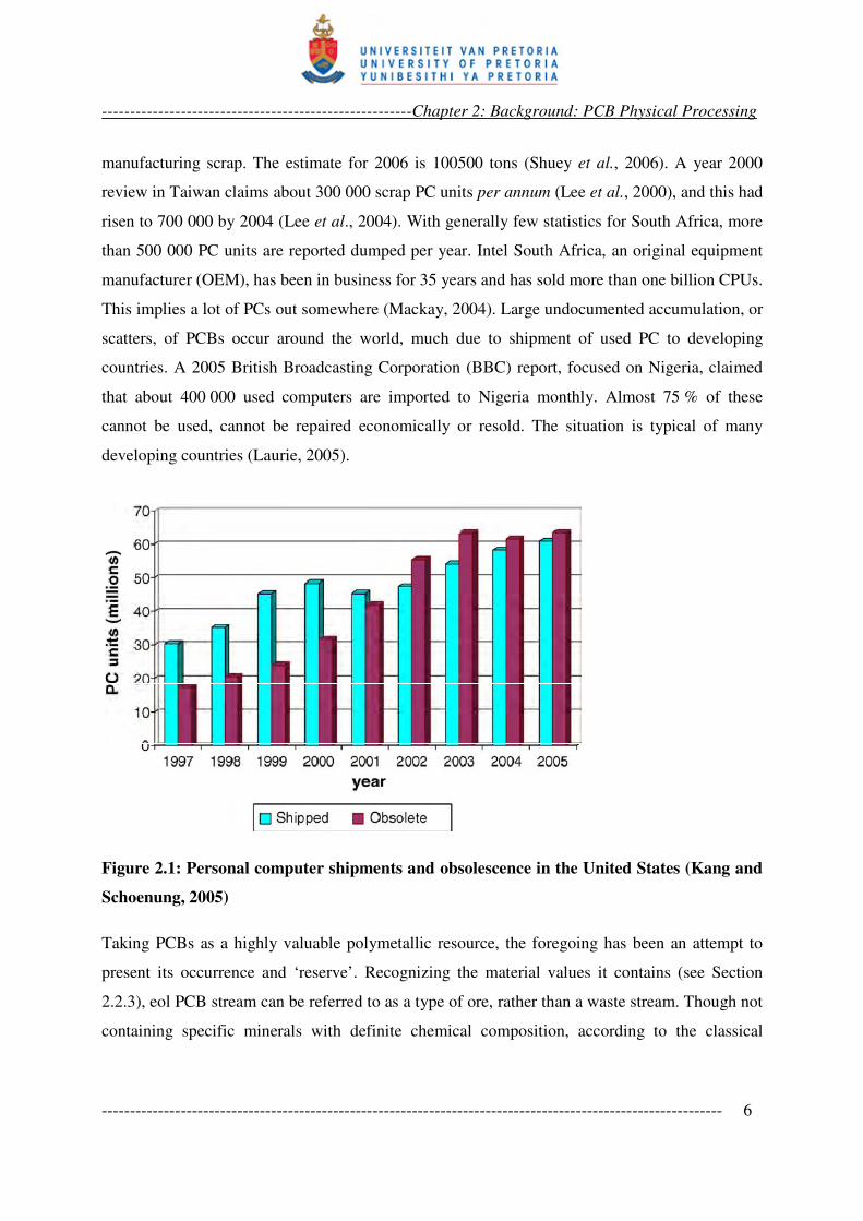
PCB structures have varied with technological advances over time. Earlier boards were single-
sided with large components on one side of the board and the soldering for mechanical support
on the order side. Etched copper wiring makes electrical connections from the soldering side (see
Figure 2.2). All the components had terminals dipping through the board. The top side and the
bottom side were therefore referred to as the component side and the solder side, respectively
(Holm, 2001). This type of boards was used in very primitive circuits.
Figure 2.2: Single sided boards
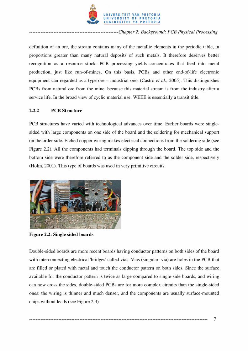
Double-sided boards are more recent boards having conductor patterns on both sides of the board
with interconnecting electrical 'bridges' called vias. Vias (singular: via) are holes in the PCB that
are filled or plated with metal and touch the conductor pattern on both sides. Since the surface
available for the conductor pattern is twice as large compared to single-side boards, and wiring
can now cross the sides, double-sided PCBs are for more complex circuits than the single-sided
ones: the wiring is thinner and much denser, and the components are usually surface-mounted
chips without leads (see Figure 2.3).
-------------------------------------------------------Chapter 2: Background: PCB Physical Processing
-------------------------------------------------------------------------------------------------------------- 8
Figure 2.3: Double-sided PCBs – top (left) and bottom (right) views
Multilayered boards are developments on the double-sided boards and are formed by bonding
together separately etched thin boards such that these boards have trace (wiring) layers inside the
compact board. Two, four, eight, twelve and sixteen layers boards have been produced (Vinod
and Sanjay, 2005; Wikipedia). The conducting traces are connected through vias. Either the
holes are electroplated or small rivets are inserted. Such high-density PCBs have blind vias,
which are visible only on one surface, or buried vias, connecting the interlayer, and so not visible
on either surfaces. In 2005, multilayered boards accounted for about 20 % of total PCB
production (Vinod and Sanjay, 2005), and manufacturers are confident this will become the
dominant type of board. Rigid flex and flexible printed circuits are other types of boards found in
specialised applications like printers and communication equipment.
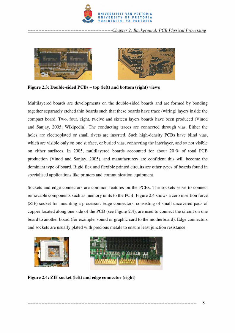
Sockets and edge connectors are common features on the PCBs. The sockets serve to connect
removable components such as memory units to the PCB. Figure 2.4 shows a zero insertion force
(ZIF) socket for mounting a processor. Edge connectors, consisting of small uncovered pads of
copper located along one side of the PCB (see Figure 2.4), are used to connect the circuit on one
board to another board (for example, sound or graphic card to the motherboard). Edge connectors
and sockets are usually plated with precious metals to ensure least junction resistance.
Figure 2.4: ZIF socket (left) and edge connector (right)
-------------------------------------------------------Chapter 2: Background: PCB Physical Processing
-------------------------------------------------------------------------------------------------------------- 9
2.2.3 PCB Material Make-Up
The materials make-up of PCB is very diverse. Populated PCBs are reported to contain most of
the elements in the periodic table (Li et al., 2004). Unpopulated boards consists of conducting
copper traces and non-conducting substrate. During production of the printed wiring by etching,
thin film of metals such as nickel, silver, tin, tin-lead and gold are used as etch-resistant materials
to protect part of the copper layer which will represent the wiring from the etchant. The substrate
is a composite material. It originally consisted of woven glass fibre impregnated with an epoxy
resin matrix containing bromine additive as flame retardant.
The matrix material called FR4 was the industry standard for many years until environmental
concern started protesting against the use of the material because of its hazardous brominated
flame retardant (BFR) content (Directive 2002/95/EC; D’Silva, 2004). This led to the
development of various halogen-free materials. Phosphorus and antimony additives have been
used for flame retardants. Up to five types of halogen free epoxy resins have been tested
qualified for use in PCB production. These include epoxy resin cross linked with aminophenyl
phosphate (Ehrler, 2002; Mauerer, 2005). There have also been developments toward improving
the Tg (glass transition temperature) of the board material using epoxy resin blends and
alternative resin materials. From the PCB materials development efforts, quite a number of
plastic materials can now be found in waste PCB (Ehrler, 2002). These include:
• The conventional FR-4.
• Higher Tg FR-4, with a higher content of tetra- or multifunctional epoxy resins in the
formulation to give greater cross-linking density in the cured material.
• Cyanate ester (CE) resin based, also with a relatively high Tg.
• GETEKR/MEGTRON resin, a blend of 70/30 high Tg epoxy and thermoplastic
polyphenylene oxide (PPO), developed by General Electric.
• Bismaleimide-triazine (BT) based material, developed by Mitsubishi Gas Chemical.
• Hydrocarbon resin filled with fine grained ceramics, designed for high frequency high speed
applications by Rogers.
• A-PPE resin, in which polyphenylene oxide has been modified into a thermosetting resin
-------------------------------------------------------Chapter 2: Background: PCB Physical Processing
-------------------------------------------------------------------------------------------------------------- 10
• ThermountR reinforced materials: a para-aramyd polymer fibre reinforced material
developed by ThermountR DuPont Advance Fibre Systems.
Alternative reinforcement materials to glass fibres have also been developed. The paper-like
para-aramid polymer fibre called KevlarR for Thermount
R is an example. Details about the
thermomechanical and electrical properties significant for PCB applications, such as the
dielectric constants, dissipation factor, through hole reliability, copper peel strength, z-axis
expansion, volume resistivity and solder shock laminate, are available in literature (Roesch and
Ehrler, 1997; Ehrler, 2002).
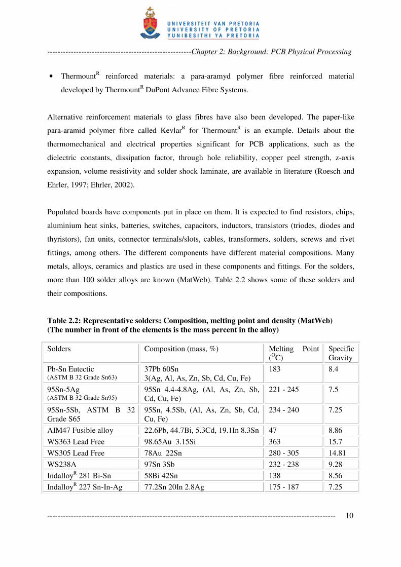
Populated boards have components put in place on them. It is expected to find resistors, chips,
aluminium heat sinks, batteries, switches, capacitors, inductors, transistors (triodes, diodes and
thyristors), fan units, connector terminals/slots, cables, transformers, solders, screws and rivet
fittings, among others. The different components have different material compositions. Many
metals, alloys, ceramics and plastics are used in these components and fittings. For the solders,
more than 100 solder alloys are known (MatWeb). Table 2.2 shows some of these solders and
their compositions.
Table 2.2: Representative solders: Composition, melting point and density (MatWeb)
(The number in front of the elements is the mass percent in the alloy)
Solders Composition (mass, %) Melting Point
(OC)
Specific
Gravity
Pb-Sn Eutectic (ASTM B 32 Grade Sn63)
37Pb 60Sn
3(Ag, Al, As, Zn, Sb, Cd, Cu, Fe)
183 8.4
95Sn-5Ag (ASTM B 32 Grade Sn95)
95Sn 4.4-4.8Ag, (Al, As, Zn, Sb,
Cd, Cu, Fe)
221 - 245 7.5
95Sn-5Sb, ASTM B 32
Grade S65
95Sn, 4.5Sb, (Al, As, Zn, Sb, Cd,
Cu, Fe)
234 - 240 7.25
AIM47 Fusible alloy 22.6Pb, 44.7Bi, 5.3Cd, 19.1In 8.3Sn 47 8.86
WS363 Lead Free 98.65Au 3.15Si 363 15.7
WS305 Lead Free 78Au 22Sn 280 - 305 14.81
WS238A 97Sn 3Sb 232 - 238 9.28
IndalloyR 281 Bi-Sn 58Bi 42Sn 138 8.56
IndalloyR 227 Sn-In-Ag 77.2Sn 20In 2.8Ag 175 - 187 7.25
-------------------------------------------------------Chapter 2: Background: PCB Physical Processing
-------------------------------------------------------------------------------------------------------------- 11
Leaded solders are expected in earlier boards, while more recent boards may use unleaded
solders. Base metals such as iron (in screws, transformers, electromagnets and rivets), copper (in
inductors, transformers and cables), aluminium (in heat sinks, foils and wrappings) and tin, can
be found in fair bulk sizes on PCBs. Rare metals, such as tantalum, are found in high
performance capacitors. Noble metals, such as gold, silver and palladium, occur in sockets and
edge connector plating and in some high performance components. Gallium and other platinum
group elements can also be found. Lead, cadmium, chromium and mercury are usually
concentrated in batteries. Mercury is also found in relays and switches, while cadmium is found
in some surface-mounted chip resistors, infrared detectors and semiconductors. Ceramics, used
in bridges and slots on the boards, include alumina and beryllium oxide. Silica, other alkaline
earth oxides, mica and barium titanate are also found. Chip components contain elements such as
Ga, In, Ti, Si, Ge, As, Sb, Se and Te, while semiconductors contain Ge, Si, Se, Ga and other
elements in small quantities.
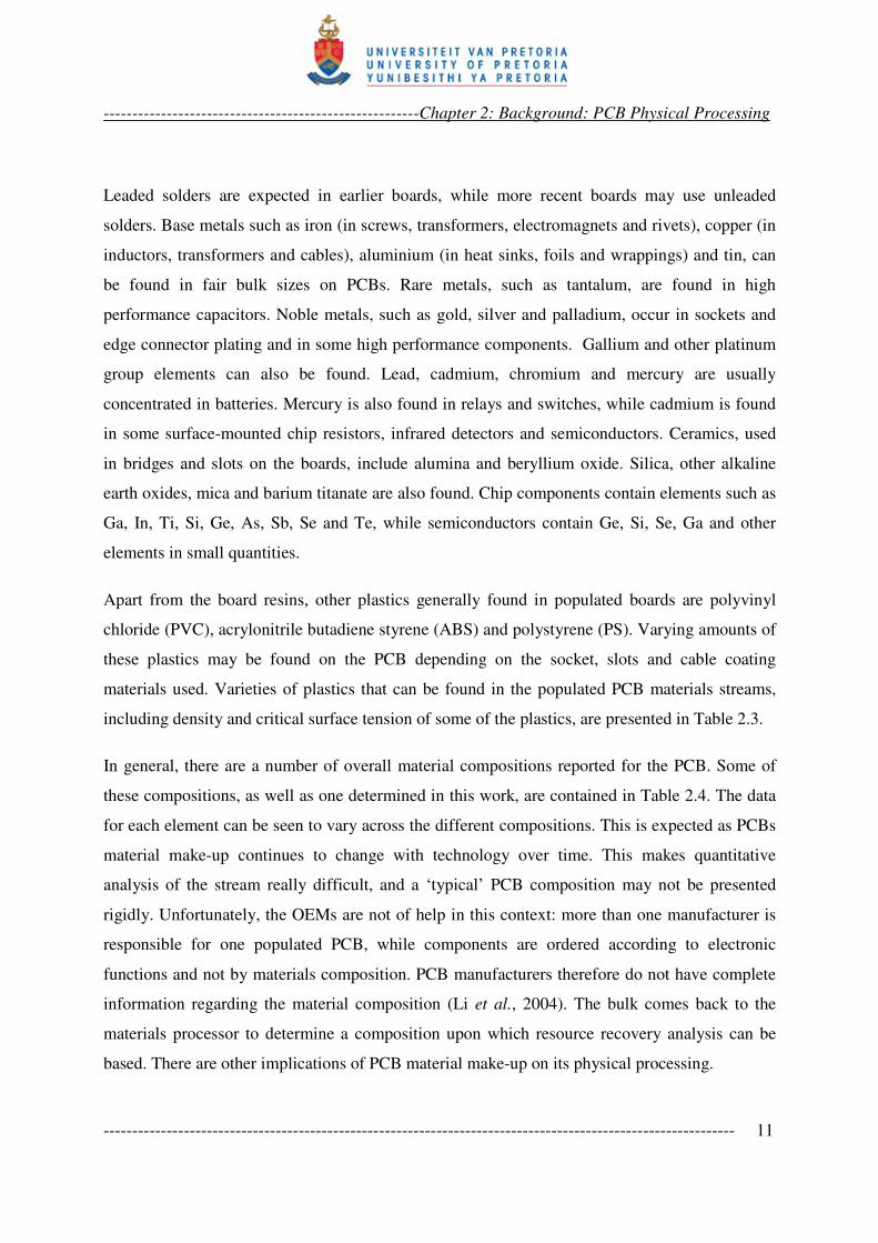
Apart from the board resins, other plastics generally found in populated boards are polyvinyl
chloride (PVC), acrylonitrile butadiene styrene (ABS) and polystyrene (PS). Varying amounts of
these plastics may be found on the PCB depending on the socket, slots and cable coating
materials used. Varieties of plastics that can be found in the populated PCB materials streams,
including density and critical surface tension of some of the plastics, are presented in Table 2.3.
In general, there are a number of overall material compositions reported for the PCB. Some of
these compositions, as well as one determined in this work, are contained in Table 2.4. The data
for each element can be seen to vary across the different compositions. This is expected as PCBs
material make-up continues to change with technology over time. This makes quantitative
analysis of the stream really difficult, and a ‘typical’ PCB composition may not be presented
rigidly. Unfortunately, the OEMs are not of help in this context: more than one manufacturer is
responsible for one populated PCB, while components are ordered according to electronic
functions and not by materials composition. PCB manufacturers therefore do not have complete
information regarding the material composition (Li et al., 2004). The bulk comes back to the
materials processor to determine a composition upon which resource recovery analysis can be
based. There are other implications of PCB material make-up on its physical processing.
-------------------------------------------------------Chapter 2: Background: PCB Physical Processing
-------------------------------------------------------------------------------------------------------------- 12
Table 2.3: Plastics obtainable from PCB materials streams
Plastics Specific Gravity γc, critical surface tension
Polyethylene (PE) 31
Polyethylene terephthalate (PET) 1.33 – 1.37 43
Polyvinylchloride (PVC) 1.16 – 1.38 39
Polytetrafluorethane (PTFE) 2.3 – 2.32 18
Nylon 1.1 – 1.35
Polypropylene (PP)
Acrylonitrile butadiene styrene – ABS 1.04 35
Fibre reinforced ABS
(Acrylonitrile butadiene styrene)
1.286 - 1.45
Polystrene (PS) 1.04 33
Cyanate Ester (CE) Resin
Polyphenylene oxides (PPO)Resin
Polyphenylene ether (PPE)
Bismaleimide-Triazine (BT) Resin
FR-4 Epoxy resin 1.8-2 47
FR-2 Phenolic resin based
Para-aramid polymer fibre
2.2.4 Physical Processing Implications
The material make-up of PCB has implication both on the comminution and the separation
operations in the physical processing. The PCB structure presented shows that classical mineral
processing comminution equipment such as gyratory/jaw crushers and tumbling mills will not
apply because brittle cleavage or shatter fracture may not be expected from PCBs. This was
demonstrated by trial comminution in a laboratory ball mill with 35 mm steel balls. The
fragments were only rubbed and beaten smooth after twenty minutes of operation (Ogunniyi,
2006). Shear shredders, which can be considered as a modification of toothed roll crushers, are
used mostly for primary crushing, while hammer mills, which employ impact and shear, are
mostly used for the grinding operation (Taylor, 2002; Goosey and Kellner, 2003; Hamos GmbH;
Sander et al., 2004, Schubert and Bernotat, 2004). Grinding in impact equipment with cryogenic
conditioning to enhance the brittleness of the polymer matrix has also been reported
(Kravchencko et al., 1983; Goosey and Kellner, 2002). It should be noted that PCB comminution
-------------------------------------------------------Chapter 2: Background: PCB Physical Processing
-------------------------------------------------------------------------------------------------------------- 13
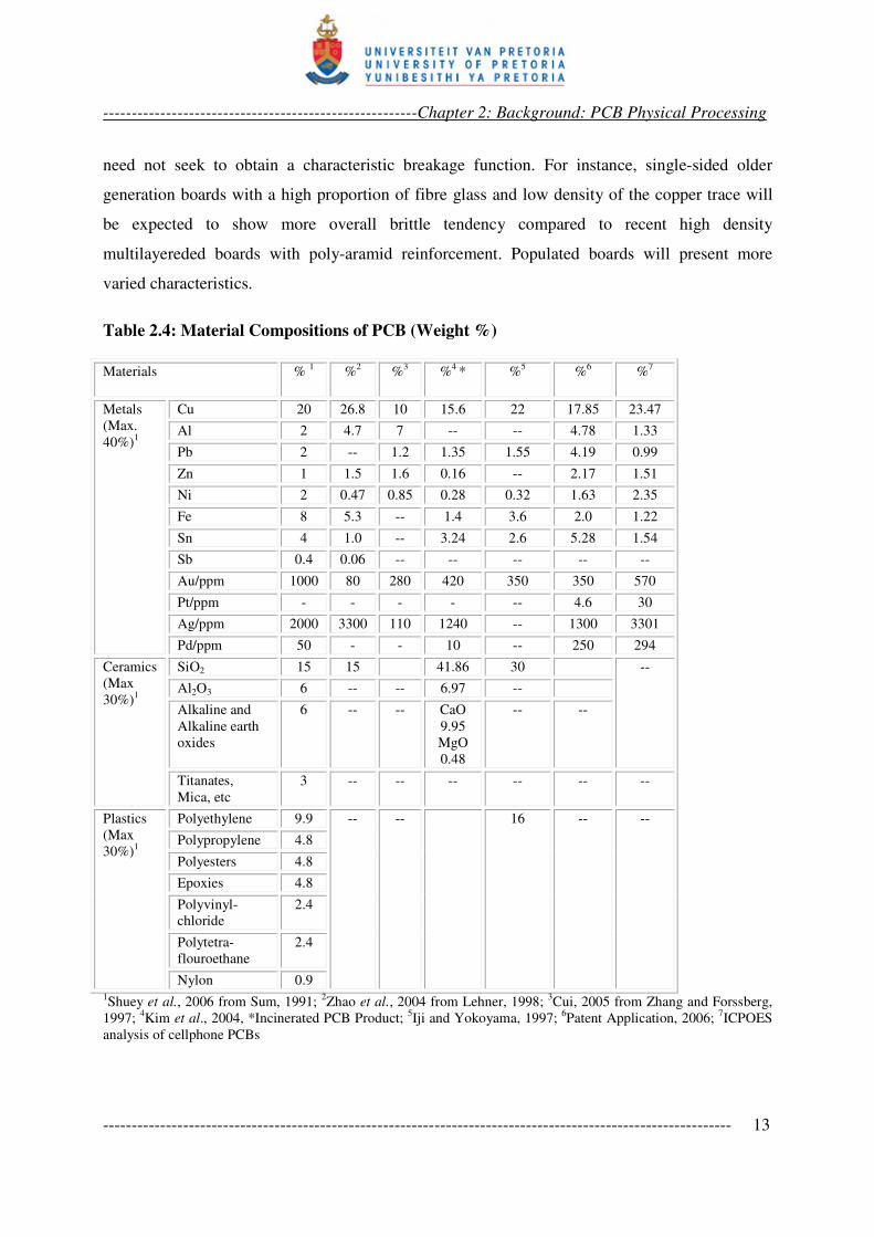
need not seek to obtain a characteristic breakage function. For instance, single-sided older
generation boards with a high proportion of fibre glass and low density of the copper trace will
be expected to show more overall brittle tendency compared to recent high density
multilayereded boards with poly-aramid reinforcement. Populated boards will present more
varied characteristics.
Table 2.4: Material Compositions of PCB (Weight %)
Materials % 1 %
2 %
3 %
4 * %
5 %
6 %
7
Metals
(Max.
40%)1
Cu 20 26.8 10 15.6 22 17.85 23.47
Al 2 4.7 7 -- -- 4.78 1.33
Pb 2 -- 1.2 1.35 1.55 4.19 0.99
Zn 1 1.5 1.6 0.16 -- 2.17 1.51
Ni 2 0.47 0.85 0.28 0.32 1.63 2.35
Fe 8 5.3 -- 1.4 3.6 2.0 1.22
Sn 4 1.0 -- 3.24 2.6 5.28 1.54
Sb 0.4 0.06 -- -- -- -- --
Au/ppm 1000 80 280 420 350 350 570
Pt/ppm - - - - -- 4.6 30
Ag/ppm 2000 3300 110 1240 -- 1300 3301
Pd/ppm 50 - - 10 -- 250 294
Ceramics
(Max
30%)1
SiO2 15 15 41.86 30 --
Al2O3 6 -- -- 6.97 --
Alkaline and
Alkaline earth
oxides
6 -- -- CaO
9.95
MgO
0.48
-- --
Titanates,
Mica, etc
3 -- -- -- -- -- --
Plastics
(Max
30%)1
Polyethylene 9.9 -- -- 16 -- --
Polypropylene 4.8
Polyesters 4.8
Epoxies 4.8
Polyvinyl-
chloride
2.4
Polytetra-
flouroethane
2.4
Nylon 0.9 1Shuey et al., 2006 from Sum, 1991;
2Zhao et al., 2004 from Lehner, 1998;
3Cui, 2005 from Zhang and Forssberg,
1997; 4Kim et al., 2004, *Incinerated PCB Product;
5Iji and Yokoyama, 1997;
6Patent Application, 2006;
7ICPOES
analysis of cellphone PCBs
-------------------------------------------------------Chapter 2: Background: PCB Physical Processing
-------------------------------------------------------------------------------------------------------------- 14
Another consequence of the diversity of valued constituents on PCBs is the complexity of
beneficiation into clean material fractions. Target metallic values range from percentages to ppm
proportions, in various forms of man-made ‘occurrences’ or ‘dissemination’. Among the
valuables are hazardous contents. Lead, mercury, cadmium, hexavalent chromium and
polychlorinated biphenyl (pcb) are among the six materials declared hazardous in the RoHS
(Restriction on Hazardous Substances) directives (Directive 2002/95/EC). Polychlorinated
biphenyl is found in some capacitors, while batteries contain cadmium, mercury, lead and
chromium. These components must not be ground along with others, but must be removed for
separate treatment (see section 2.2.3). This is why physical processing has to be in stages of
comminution-separation, decongesting the stream as comminution progresses to finer sizes, and
different values are being liberated. In this manner, the materials variety would have been
significantly reduced before final grinding to liberate the values within the laminates.
2.3 PCB PHYSICAL PROCESSING OPERATIONS
In the 1970s the predominant method of recovery of metals from electronic scrap was via the
blast furnace in conjunction with secondary copper/lead smelter (Sum, 1991). Details about
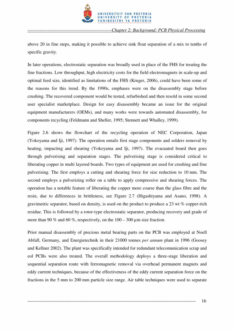
physical processing effort were rare until the early 1980s. Figure 2.5 is a typical flowchart of
earlier physical processing of scrap from multi-component REE – radio-electronics equipment
(Kravchenko et al., 1983). Scrap REE has now taken on the WEEE nomenclature. Features of
this processing included differentiated disassembly (more recently referred to as selective
disassembly), cryogenic cooling and crushing, airflow classification, stages of magnetic
separations and, finally, magneto-hydrostatic separation (MHS). The magneto-hydrostatic
separation density was first set to 2000 kg/m3 (2 g/cm
3), then to 3000 kg/m
3. This will cause non-
metallic stuff to be floated first, followed by aluminum in the second stage, while copper, lead
and tin were in the sink product.
-------------------------------------------------------Chapter 2: Background: PCB Physical Processing
-------------------------------------------------------------------------------------------------------------- 15
Figure 2.5: Flowsheet for reprocessing of multicomponent REE scrap (Kravchencko et al.,
1983 - Redrawn)
Magneto-hydrostatic separation, also called ferro-hydrostatic separation (FHS), is a technology
that uses colloidally stable and magnetizable fluids. It dates back a few decades, with reported
application for municipal solid waste processing (Khalafalla, 1973, 1976; Zhan and Shenton,
1980; Vesilind and Rimer, 1981). More recently, Debeers group reported efforts to apply it to
mineral processing (Svoboda, 2000). A suspension of nanosized magnetic particles (often in
kerosene) forms the ferrofluid whose apparent density can be varied by its surrounding magnetic
field; the apparent density increases with increasing field strength. Under the influence of the
field, the nanoparticles tend to align in space inside the ferrofluid and become stationary. This
tends to make the fluid rigid so that particles sink through it with greater resistance, making the
density appear higher. In application, the apparent density can be varied up to a specific gravity
REE Scrap
Removable
units & parts
Cryogenic cooling
Differential dismantling
Assemblies containing
Co, W, Ag, Au
Metallic
components
Crushing
Air separation
Non metallic waste I stage of magnetic separation
Non-metallic
wastes
Aluminum concentrate
II stage of magnetic separation
Ferrous metals
(Vtorchermet)
Non ferrous metals with iron
to fusion furnace MHS-separation
Heavy non-
ferrous metals
-------------------------------------------------------Chapter 2: Background: PCB Physical Processing
-------------------------------------------------------------------------------------------------------------- 16
above 20 in fine steps, making it possible to achieve sink float separation of a mix to tenths of
specific gravity.
In later operations, electrostatic separation was broadly used in place of the FHS for treating the
fine fractions. Low throughput, high electricity costs for the field electromagnets in scale-up and
optimal feed size, identified as limitations of the FHS (Kruger, 2006), could have been some of
the reasons for this trend. By the 1990s, emphases were on the disassembly stage before
crushing. The recovered component would be tested, refurbished and then resold in some second
user specialist marketplace. Design for easy disassembly became an issue for the original
equipment manufacturers (OEMs), and many works were towards automated disassembly, for
components recycling (Feldmann and Sheller, 1995; Stennett and Whalley, 1999).
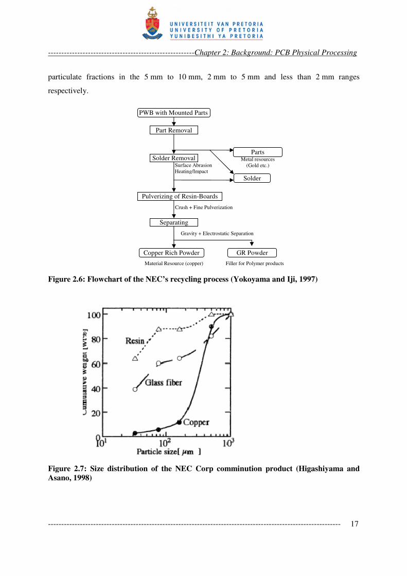
Figure 2.6 shows the flowchart of the recycling operation of NEC Corporation, Japan
(Yokoyama and Iji, 1997). The operation entails first stage components and solders removal by
heating, impacting and shearing (Yokoyama and Iji, 1997). The evacuated board then goes
through pulverising and separation stages. The pulverising stage is considered critical to
liberating copper in multi layered boards. Two types of equipment are used for crushing and fine
pulverising. The first employs a cutting and shearing force for size reduction to 10 mm. The
second employs a pulverizing roller on a table to apply compressive and shearing forces. The
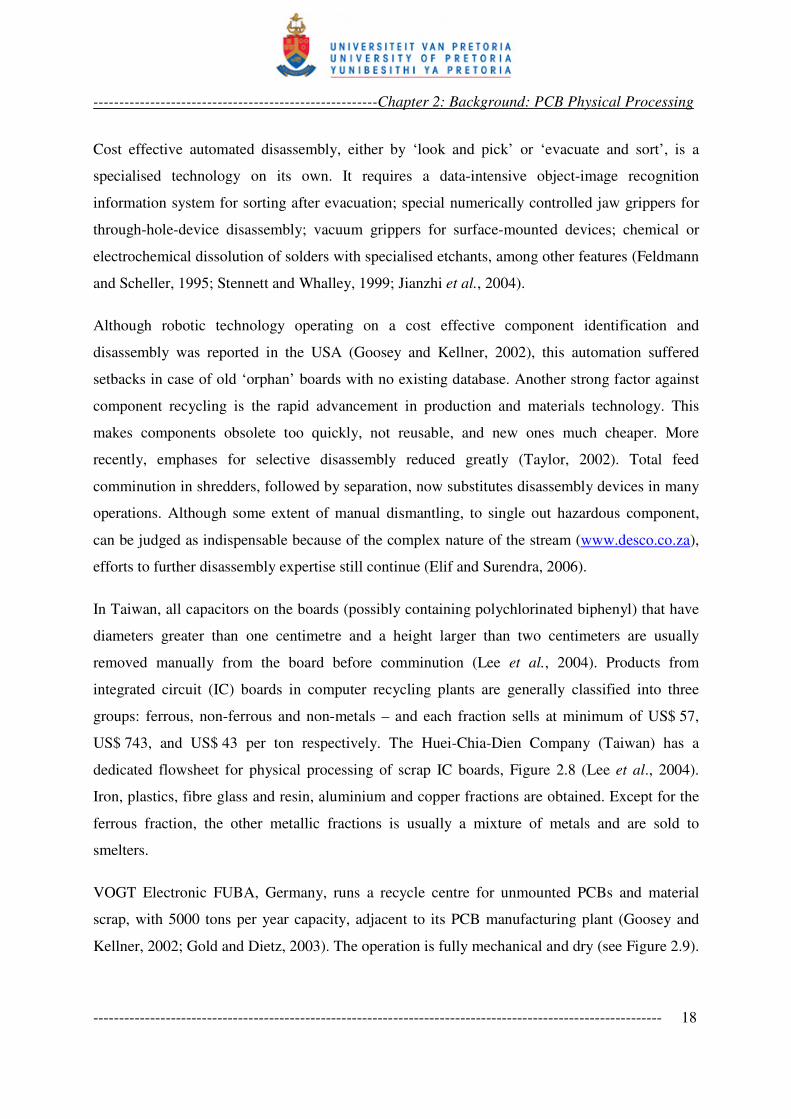
operation has a notable feature of liberating the copper more coarse than the glass fibre and the
resin, due to differences in brittleness, see Figure 2.7 (Higashiyama and Asano, 1998). A
gravimetric separator, based on density, is used on the product to produce a 23 wt % copper-rich
residue. This is followed by a rotor-type electrostatic separator, producing recovery and grade of
more than 90 % and 60 %, respectively, on the 100 – 300 µm size fraction.
Prior manual disassembly of precious metal bearing parts on the PCB was employed at Noell
Abfall, Germany, and Energietechnik in their 21000 tonnes per annum plant in 1996 (Goosey
and Kellner 2002). The plant was specifically intended for redundant telecomunication scrap and
eol PCBs were also treated. The overall methodology deploys a three-stage liberation and
sequential separation route with ferromagnetic removal via overhead permanent magnets and
eddy current techniques, because of the effectiveness of the eddy current separation force on the
fractions in the 5 mm to 200 mm particle size range. Air table techniques were used to separate
-------------------------------------------------------Chapter 2: Background: PCB Physical Processing
-------------------------------------------------------------------------------------------------------------- 17
particulate fractions in the 5 mm to 10 mm, 2 mm to 5 mm and less than 2 mm ranges
respectively.
Figure 2.6: Flowchart of the NEC’s recycling process (Yokoyama and Iji, 1997)
Figure 2.7: Size distribution of the NEC Corp comminution product (Higashiyama and
Asano, 1998)
Gravity + Electrostatic Separation
Crush + Fine Pulverization
Material Resource (copper) Filler for Polymer products
Pulverizing of Resin-Boards
Separating
Copper Rich Powder GR Powder
Metal resources
(Gold etc.) Surface Abrasion
Heating/Impact
Part Removal
Solder Removal
PWB with Mounted Parts
Solder
Parts
-------------------------------------------------------Chapter 2: Background: PCB Physical Processing
-------------------------------------------------------------------------------------------------------------- 18
Cost effective automated disassembly, either by ‘look and pick’ or ‘evacuate and sort’, is a
specialised technology on its own. It requires a data-intensive object-image recognition
information system for sorting after evacuation; special numerically controlled jaw grippers for
through-hole-device disassembly; vacuum grippers for surface-mounted devices; chemical or
electrochemical dissolution of solders with specialised etchants, among other features (Feldmann
and Scheller, 1995; Stennett and Whalley, 1999; Jianzhi et al., 2004).
Although robotic technology operating on a cost effective component identification and
disassembly was reported in the USA (Goosey and Kellner, 2002), this automation suffered
setbacks in case of old ‘orphan’ boards with no existing database. Another strong factor against
component recycling is the rapid advancement in production and materials technology. This
makes components obsolete too quickly, not reusable, and new ones much cheaper. More
recently, emphases for selective disassembly reduced greatly (Taylor, 2002). Total feed
comminution in shredders, followed by separation, now substitutes disassembly devices in many
operations. Although some extent of manual dismantling, to single out hazardous component,
can be judged as indispensable because of the complex nature of the stream (www.desco.co.za),
efforts to further disassembly expertise still continue (Elif and Surendra, 2006).
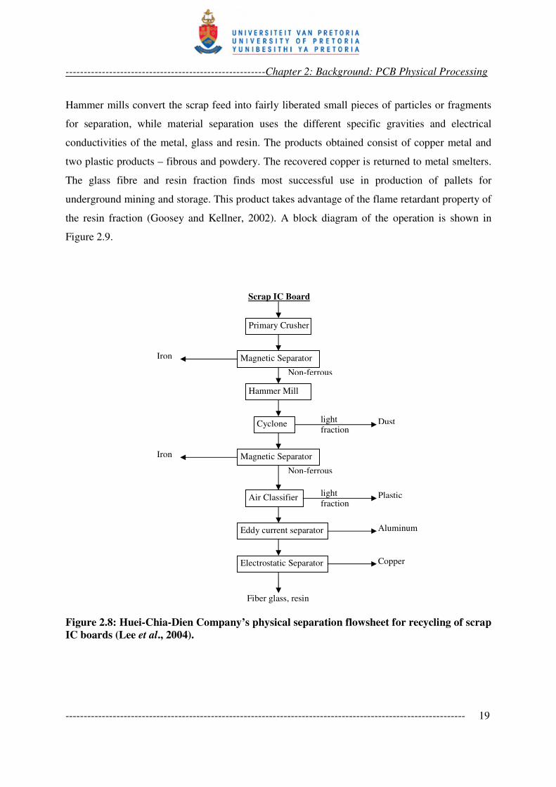
In Taiwan, all capacitors on the boards (possibly containing polychlorinated biphenyl) that have
diameters greater than one centimetre and a height larger than two centimeters are usually
removed manually from the board before comminution (Lee et al., 2004). Products from
integrated circuit (IC) boards in computer recycling plants are generally classified into three
groups: ferrous, non-ferrous and non-metals – and each fraction sells at minimum of US$ 57,
US$ 743, and US$ 43 per ton respectively. The Huei-Chia-Dien Company (Taiwan) has a
dedicated flowsheet for physical processing of scrap IC boards, Figure 2.8 (Lee et al., 2004).
Iron, plastics, fibre glass and resin, aluminium and copper fractions are obtained. Except for the
ferrous fraction, the other metallic fractions is usually a mixture of metals and are sold to
smelters.
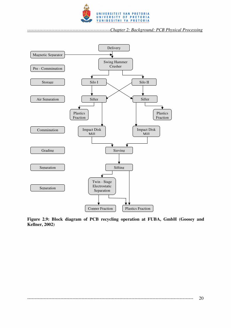
VOGT Electronic FUBA, Germany, runs a recycle centre for unmounted PCBs and material
scrap, with 5000 tons per year capacity, adjacent to its PCB manufacturing plant (Goosey and
Kellner, 2002; Gold and Dietz, 2003). The operation is fully mechanical and dry (see Figure 2.9).
-------------------------------------------------------Chapter 2: Background: PCB Physical Processing
-------------------------------------------------------------------------------------------------------------- 19
Hammer mills convert the scrap feed into fairly liberated small pieces of particles or fragments
for separation, while material separation uses the different specific gravities and electrical
conductivities of the metal, glass and resin. The products obtained consist of copper metal and
two plastic products – fibrous and powdery. The recovered copper is returned to metal smelters.
The glass fibre and resin fraction finds most successful use in production of pallets for
underground mining and storage. This product takes advantage of the flame retardant property of
the resin fraction (Goosey and Kellner, 2002). A block diagram of the operation is shown in
Figure 2.9.
Figure 2.8: Huei-Chia-Dien Company’s physical separation flowsheet for recycling of scrap
IC boards (Lee et al., 2004).
Non-ferrous
Non-ferrous
Primary Crusher
Magnetic Separator
Hammer Mill
Cyclone
Magnetic Separator
Air Classifier
Eddy current separator
Electrostatic Separator
Scrap IC Board
Iron
light
fraction Dust
Iron
Plastic light
fraction
Aluminum
Copper
Fiber glass, resin
-------------------------------------------------------Chapter 2: Background: PCB Physical Processing
-------------------------------------------------------------------------------------------------------------- 20
Figure 2.9: Block diagram of PCB recycling operation at FUBA, GmbH (Goosey and
Kellner, 2002)
Delivery
Swing Hammer
Crusher
Silo I Silo II
Sifter Sifter
Plastics
Fraction
Plastics
Fraction
Impact Disk
Mill
Impact Disk
Mill
Sieving
Sifting
Twin - Stage
Electrostatic
Separation
Copper Fraction Plastics Fraction
Magnetic Separator
Pre - Comminution
Storage
Air Separation
Comminution
Grading
Separation
Separation
-------------------------------------------------------Chapter 2: Background: PCB Physical Processing
-------------------------------------------------------------------------------------------------------------- 21
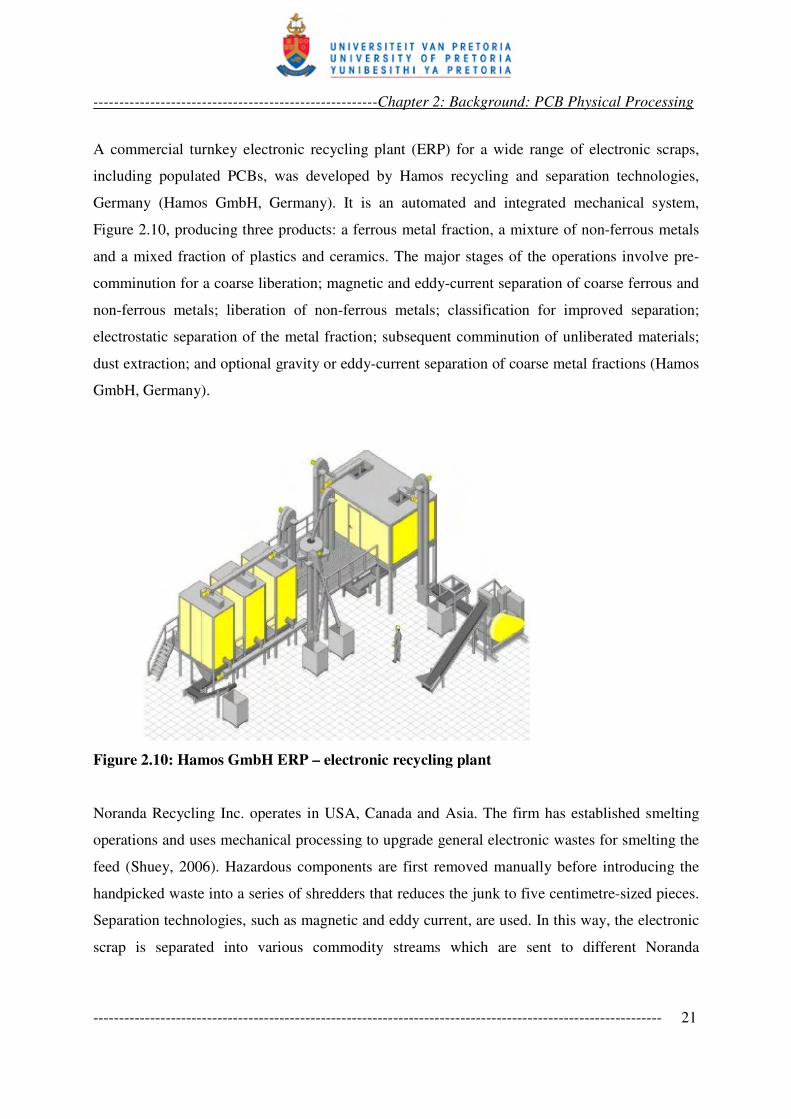
A commercial turnkey electronic recycling plant (ERP) for a wide range of electronic scraps,
including populated PCBs, was developed by Hamos recycling and separation technologies,
Germany (Hamos GmbH, Germany). It is an automated and integrated mechanical system,
Figure 2.10, producing three products: a ferrous metal fraction, a mixture of non-ferrous metals
and a mixed fraction of plastics and ceramics. The major stages of the operations involve pre-
comminution for a coarse liberation; magnetic and eddy-current separation of coarse ferrous and
non-ferrous metals; liberation of non-ferrous metals; classification for improved separation;
electrostatic separation of the metal fraction; subsequent comminution of unliberated materials;
dust extraction; and optional gravity or eddy-current separation of coarse metal fractions (Hamos
GmbH, Germany).
Figure 2.10: Hamos GmbH ERP – electronic recycling plant
Noranda Recycling Inc. operates in USA, Canada and Asia. The firm has established smelting
operations and uses mechanical processing to upgrade general electronic wastes for smelting the
feed (Shuey, 2006). Hazardous components are first removed manually before introducing the
handpicked waste into a series of shredders that reduces the junk to five centimetre-sized pieces.
Separation technologies, such as magnetic and eddy current, are used. In this way, the electronic
scrap is separated into various commodity streams which are sent to different Noranda
-------------------------------------------------------Chapter 2: Background: PCB Physical Processing
-------------------------------------------------------------------------------------------------------------- 22
operations. Fractions rich in copper and precious metals, copper-plastic mixed fraction and
circuit boards are sent to the copper smelting operations to recover copper, silver, gold, platinum,
palladium, selenium, tellurium, cadmium and nickel. The steel output from the mechanical
processing goes directly to the steel foundry, while the aluminium fraction goes to an aluminium
smelter. As Noranda’s products are dedicated to established smelters, the mechanical processing
does not try to achieve the best clean material fractions possible.
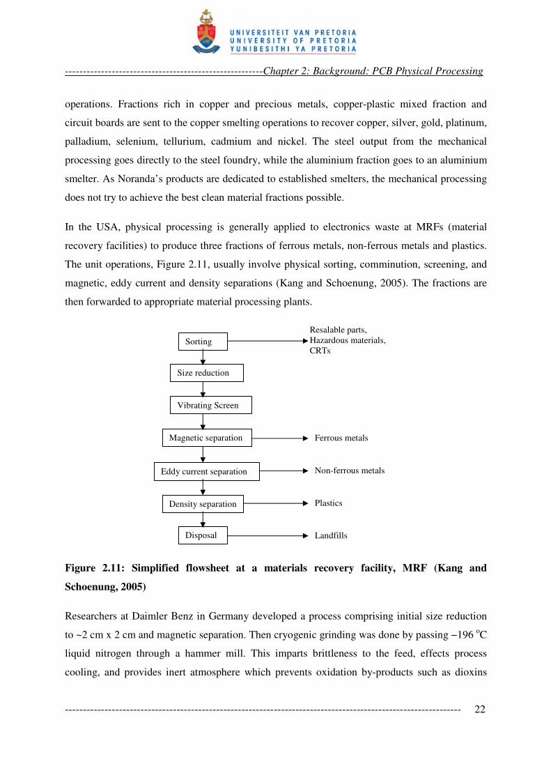
In the USA, physical processing is generally applied to electronics waste at MRFs (material
recovery facilities) to produce three fractions of ferrous metals, non-ferrous metals and plastics.
The unit operations, Figure 2.11, usually involve physical sorting, comminution, screening, and
magnetic, eddy current and density separations (Kang and Schoenung, 2005). The fractions are
then forwarded to appropriate material processing plants.
Figure 2.11: Simplified flowsheet at a materials recovery facility, MRF (Kang and
Schoenung, 2005)
Researchers at Daimler Benz in Germany developed a process comprising initial size reduction
to ~2 cm x 2 cm and magnetic separation. Then cryogenic grinding was done by passing −196 oC
liquid nitrogen through a hammer mill. This imparts brittleness to the feed, effects process
cooling, and provides inert atmosphere which prevents oxidation by-products such as dioxins
Resalable parts,
Hazardous materials,
CRTs Sorting
Size reduction
Vibrating Screen
Magnetic separation
Eddy current separation
Density separation
Disposal
Ferrous metals
Non-ferrous metals
Plastics
Landfills
-------------------------------------------------------Chapter 2: Background: PCB Physical Processing
-------------------------------------------------------------------------------------------------------------- 23
and furans. Sieving and electrostatic separation is applied for material separation of the milled
product (Goosey and Kellner, 2002).
In South Africa, two major recyclers – Desco Electronic Recyclers and Universal Recycling
Company – are known in the e-waste recycling industry. Of these, only Desco Electronic
Recyclers is reported to have dedicated PCB processing operation (eWaste Guide, 2006; Finlay,
2005). Another establishment, Reclaim, is considered to be the largest recycling organisation in
South Africa. It also accepts e-waste, but passes it onto Universal Recycling (Finlay, 2005).
Other minor players basically serve as collectors and pass on the general e-waste to any of the
two major establishments. African Sky, who also accepts e-waste, carries out very minimal
processing or value addition before exporting the stock virtually as-received to Citiraya waste
recycling company in Singapore (Finlay, 2005). Citiraya, which now operates as Centillion
Environment and Recycling UK Limited (www.centillion-er.com;
www.researchandmarkets.com), is considered to be one of the world biggest processor of
corporate e-waste and deals with multinationals such as Nokia and HP (Finlay, 2005; eWaste
Guide, 2006).
Desco Electronic Recyclers is reported to process about 400 tons of PCBs along with about 2000
tons of other electronic waste annually (eWaste Guide, 2006). Desco strips the feed manually,
disassembles and sorts it into separate specific components and material types. Materials for
recycling are not thrown into the shredder as whole units. This prevents a mixture of plastics,
ferrous and non-ferrous materials being shredded together (www.desco.co.za). Plastics are
separated from the PCBs, producing a relatively clean plastic fraction for the final plastic
recycler clients. The boards are then shredded, followed by pulverisation, and separation stages.
The machinery used is designed and built by Desco, and the details are proprietary.
The operation at Universal Recycling is fully mechanised, without any hand sorting. The stock is
conveyed via belts between different operations. These include shredding, heavy media
separation, eddy current separation, sorting, milling, granulation and rotary magnetic separation
(www.urc.co.za). The heavy media separates the comminution products, based on densities in
stages, giving product fractions of plastics, glasses and metals. The water for the heavy media
separation is fully recycled (Finlay, 2005). The operation, however, handles the feed as a mixed
-------------------------------------------------------Chapter 2: Background: PCB Physical Processing
-------------------------------------------------------------------------------------------------------------- 24
load with no specific provision for e-waste or PCBs. Electronics are simply considered along
with non-ferrous materials. Components such as nickel-cadmium batteries, bearing hazardous
constituents all go through the shredder, but somehow along the line, they are separated (Finlay,
2005). The final products from these operations are sold mostly to Rand refineries, South Africa,
as non-ferrous fraction from waste recycling.
All these operations are basically preparatory to finishing recovery via smelting. Consequently,
clean fractions are not paramount. Except for ferrous fractions which can be achieved at fairly
high grade and recovery, optimum reports for copper, for instance, include 60 % copper grade
and 90 % recovery in 100 – 300 µm fraction (Yokoyama and Iji, 1997). FUBA operation reports
92 % copper grade from unpopulated boards, which is a less complex feed. Product grades from
many operations are rare in reports. Zhang and other workers conducted various investigations
on PCB and WEEE physical processing (Zhang et al., 1997; Zhang and Forssberg, 1997). Using
air table separation, optimum result reported 72 % grade and 76 % recovery for copper in the
1 mm to 0.6 mm mill fraction (Zhang and Forssberg, 1997).
Compared to typical assay figures in conventional minerals processing, the copper assays in the
product fractions appear satisfactory. Chalcopyrite (CuFeS2), for instance, is the main ore
mineral of copper, and the best copper assay from its processing is 34.7 %. Such chalcopyrite
concentrate is amenable to straightforward matte smelting chemistry, oxidizing iron sulphide to
the slag phase and sulphur to the gas phase, leaving metallic (blister) copper (Rosenqvist, 1988).
In contrast, for PCB non-ferrous copper rich separation products, at much higher assays, the
smelting and refining processes are much more extensive. This is because for a fraction assaying,
say, 90 % copper, the 10% complementary matter will not be from a single mineral element
(such as sulphur alone with copper in chalcocite) or a few definite co-occurring elements, but a
lot of contaminants. This is to say that, while poor separation efficiencies are obtained at non-
optimal size fractions, even the products with best grades still need improving.
From what commonly obtains at present: (i) returns to the independent physical processing plant
are not maximized (some prices are cited for Taiwan); (ii) overall recycling ratio is low (as
secondary use of unsorted fraction is limited); and (iii) secondary smelting for metallic value
recovery requires extensive facilities. Such a smelting facility, Pb-Cu smelter, is cost intensive
-------------------------------------------------------Chapter 2: Background: PCB Physical Processing
-------------------------------------------------------------------------------------------------------------- 25
and not available in many parts of the world where PCB and general electronics waste recycling
has to be done. In fact the more complex Pb-Cu-Zn smelters with facilities for recovery of metals
such as zinc from volatiles are the most appropriate. Constructing such a capital-intensive
metallurgical plant specifically for e-waste processing will require a more integrated collection
and shipping infrastructure of the waste stream. Although the pyrometallurgical follow-up route
may not be avoided outright, the downstream processing chemistry can be simplified
considerably by cleaner fractions from the physical processing.
Improving eol PCBs beneficiation demands that the material complexity involved is recognised
and an effective beneficiation operation is developed to match. While ores containing three target
minerals are considered complex in classical minerals processing, with extensive beneficiation
operation, common eol PCBs beneficiation flowsheet, are generally too brief for the task.
2.4 IMPROVING PCB PHYSICAL PROCESSING: FINES BENEFICIATION
It can be seen from the review of PCB physical processing presented that, for the −2 mm
comminution products, electrostatic separation is the technology been employed. In conventional
mineral processing, it is known that separation efficiency of corona or high tension electrostatics
separator drops rapidly below 75 µm feed sizes (Wills, 1997; Kelly and Spottiswood, 1989).
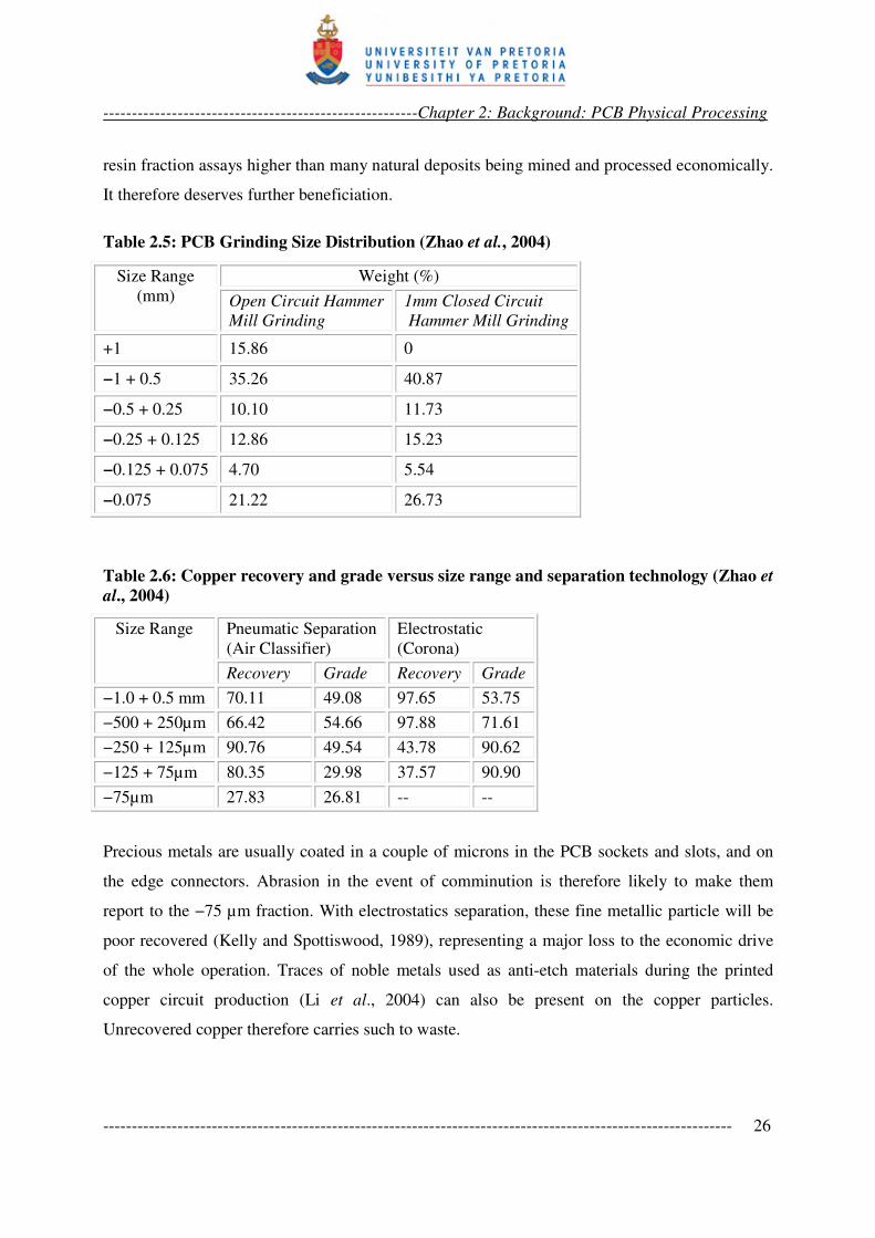
Zhao et al. (2004) compared a type of column air separator to electrostatic separator for recovery
of metal values from PCB hammer mill grinding products (Tables 2.5 and 2.6). More than 20 %
of the product of the hammer mill grinding from 30 mm feed size reported to the −75 µm
fraction, assaying almost 2.9 % copper. Copper recoveries of 27.83 % at a grade of 26.8 wt. %
were obtained from the pneumatic separator. Separation from the electrostatics at that size was
not reported, probably because it was too poor. The work concluded that below 75 µm,
electrostatic separation efficiency is poor for PCB grinding fines.
In the NEC’s operation (Yokoyama and Iji, 1997; Iji and Yokoyama, 1997), at −300 + 100 µm,
copper-rich powder (82 % Cu, at less than 90 % recovery) was produced. The non-conducting
fraction from the electrostatics separation contained 64 % glass fibre, 34 % epoxy resin, 2.1 %
copper and solders. Some end-use applications, such as filler for epoxy resin polymer product,
were investigated for the glass fibre-resin fraction. But at 2.1 % copper content, the fibre glass-
-------------------------------------------------------Chapter 2: Background: PCB Physical Processing
-------------------------------------------------------------------------------------------------------------- 26
resin fraction assays higher than many natural deposits being mined and processed economically.
It therefore deserves further beneficiation.
Table 2.5: PCB Grinding Size Distribution (Zhao et al., 2004)
Size Range
(mm)
Weight (%)
Open Circuit Hammer
Mill Grinding
1mm Closed Circuit
Hammer Mill Grinding
+1 15.86 0
−1 + 0.5 35.26 40.87
−0.5 + 0.25 10.10 11.73
−0.25 + 0.125 12.86 15.23
−0.125 + 0.075 4.70 5.54
−0.075 21.22 26.73
Table 2.6: Copper recovery and grade versus size range and separation technology (Zhao et
al., 2004)
Size Range Pneumatic Separation
(Air Classifier)
Electrostatic
(Corona)
Recovery Grade Recovery Grade
−1.0 + 0.5 mm 70.11 49.08 97.65 53.75
−500 + 250µm 66.42 54.66 97.88 71.61
−250 + 125µm 90.76 49.54 43.78 90.62
−125 + 75µm 80.35 29.98 37.57 90.90
−75µm 27.83 26.81 -- --
Precious metals are usually coated in a couple of microns in the PCB sockets and slots, and on
the edge connectors. Abrasion in the event of comminution is therefore likely to make them
report to the −75 µm fraction. With electrostatics separation, these fine metallic particle will be
poor recovered (Kelly and Spottiswood, 1989), representing a major loss to the economic drive
of the whole operation. Traces of noble metals used as anti-etch materials during the printed
copper circuit production (Li et al., 2004) can also be present on the copper particles.
Unrecovered copper therefore carries such to waste.
-------------------------------------------------------Chapter 2: Background: PCB Physical Processing
-------------------------------------------------------------------------------------------------------------- 27
The inefficiency of electrostatics separation with PCB grinding fines could have been tolerated
because (i) the relatively higher assays and better recoveries from the coarser fractions
(Yokoyama and Iji, 1997; Zhao et al., 2004) pay for the operation profitably well; (ii) the
metallic products of PCB physical separation are generally being destined to pyrometallurgical
operations (Shuey et al., 2006; Lee et al., 2004), and (iii) dry operations are preferred for
handling the PCBs.
Only the last point can make the tolerance understandable. Wet processes are avoided in most
recycling operations to avoid wash water circuit and treatment costs, among other reasons
(Kellerwessel, 1993). In particular, because PCBs contains such a wide diversity of materials,
leaching and oxidation behaviours cannot be absolutely predicted in a wet process. Also, at the
coarse fractions of the comminution-separation operation (with particles of all sorts of shapes)
particle flow will not be good. But at finer sizes, slurry flow is much better. The issue of
hazardous leaching or material oxidation still remains. It could, however, be much reduced at the
fine sizes, as many materials from many components, particularly components bearing hazardous
substances, have being removed. Materials expected will be mostly chippings from metallic
particles, copper from the traces, solder remains, ceramics used in small resistors and chips, resin
materials like epoxy, remains of plastics used in slots and reinforcement material such as glass
fibre.
At this stage of PCB physical processing, the operation need not be restricted to dry. Froth
flotation is a specific wet processing technique that appears very promising for beneficiation of
the fine fraction. Froth flotation, exploits distinct surface properties of individual particles; it is
particularly effective in the −75 µm range; and it can be executed via different schemes toward
enhancing selectivity. The prospect therefore deserves detailed investigations. An overview of
how froth flotation can be applied to this material stream will be presented in the next chapter in
order to set out a detailed methodology for the investigation.
2.5 CONCLUSION
Physical processing of PCB dates to about three decades now - not totally a new area of
endeavor, yet not fully developed. Essentially, it remains a stage-wise comminution-separation
-------------------------------------------------------Chapter 2: Background: PCB Physical Processing
-------------------------------------------------------------------------------------------------------------- 28
operation. Given the peculiar material composition of the printed circuit boards, shear shredders
can be taken as the industry standard comminution equipment used. Separation technologies
employed in the industry include magnetic, eddy-current, electrostatic, dense-medium and air-
classification. Product material fractions are ferrous, non-ferrous, plastics and ceramics, with
different degrees of cross contamination depending on particle liberation and the size at which
the material fraction was obtained. The non-ferrous fraction mostly serves as secondary feed at
established smelters having requisite extensive facilities. Hydrometallurgical follow-up route to
the physical processing has relative advantages over the pyrometallurgical routes, but it requires
much cleaner material fractions to simplify process chemistry. The −75 µm fine fraction in the
comminution products has been observed to contribute a drop to the overall recovery and
separation efficiencies. Loss of precious metals to the fine fraction is also possible, representing
a major economic loss to the operation. Froth flotation appears very promising for investigation
into its applicability for beneficiation of the metallic values deported to this fine size fraction.
---------------------------------------------------------------------------------------------------------------------
3.0 FROTH FLOTATION FOR THE BENEFICIATION OF PCB FINES
3.1 INTRODUCTION
As presented in Chapter 2, the material constituents of the comminution fines will be quite
diverse. This will include copper from the traces; solder remains; precious metals – gold,
palladium, platinum – relatively in trace proportions; chipped or torn particles of various alloys;
synthetic or natural ceramics used in certain resistors, semiconductors, glazed components and
chips; resin materials like epoxy; particles of plastics used in slots; and board reinforcement
material such as glass fiber. It follows that flotation of native metals, plastics, and ceramics
(oxides, conventional minerals) are all of relevance towards evolving logical flotation schemes
for the sample. These and other relevant concepts are reviewed in this chapter. The concepts are
used to advance probable schemes, and to make more specific objective statements for the
investigation. As this application will traverse a broad spectrum of surfactants, a brief on
surfactants are presented first.
3.2 SURFACE ACTIVE AGENTS
Surface active agents (surfactants) are organic compounds with a heteropolar molecular
structure. The non-polar hydrocarbon chain group of the molecule prefers to attach to air, while
the polar functional groups prefer aqueous phase. The surface activity derives from this property.
They can therefore adsorb (accumulate) at air-water, air-mineral and/or water-mineral interfaces.
The specific application of a surfactant is determined by the properties of the polar functional
group, which can be ionic – cationic or anionic, or non-ionic. Ionic surfactants are electrolytes.
They can adsorb at mineral-water interfaces, electrostatically and/or chemically. This makes
them useful as collectors. Non ionic surfactants are non-electrolytes, and they adsorb majorly at
air-water interface. Table 3.1 shows some common surfactants compounds. The adsorption at
air-water interface lowers the surface tension of the solution. This makes thin films of the
solution metastable and therefore supports frothing. It also creates wetting effects, lowering
overall surface energy and tension.
-----------------------------------------------Chapter 3: Froth flotation for Beneficiation of PCB fines
-------------------------------------------------------------------------------------------------------------- 30
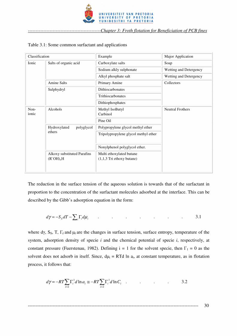
Table 3.1: Some common surfactant and applications
Classification Example Major Application
Ionic Salts of organic acid Carboxylate salts Soap
Sodium alkly sulphonate Wetting and Detergency
Alkyl phosphate salt Wetting and Detergency
Amine Salts Primary Amine Collectors
Sulphydryl Dithiocarbonates
Trithiocarbonates
Dithiophosphates
Non-
ionic
Alcohols
Methyl IsoButyl
Carbinol
Neutral Frothers
Pine Oil
Hydroxylated polyglycol
ethers
Polypropylene glycol methyl ether
Tripolypropylene glycol methyl ether
Nonylphenol polyglycol ether.
Alkoxy substituted Parafins
(R`OH)xH
Multi ethoxylated butane
(1,1,3 Tri ethoxy butane)
The reduction in the surface tension of the aqueous solution is towards that of the surfactant in
proportion to the concentration of the surfactant molecules adsorbed at the interface. This can be
described by the Gibb’s adsorption equation in the form:
∑ Γ−−=i iiS ddTSd µγ . . . . . . . 3.1
where dγ, SS, T, Γi and µi are the changes in surface tension, surface entropy, temperature of the
system, adsorption density of specie i and the chemical potential of specie i, respectively, at
constant pressure (Fuerstenau, 1982). Defining i = 1 for the solvent specie, then Γ1 = 0 as the
solvent does not adsorb in itself. Since, dµi = RTd ln ai, at constant temperature, as in flotation
process, it follows that:
∑∑==
Γ−≅Γ−=
2
1
2
1lnln
i
ii
i
ii CdRTadRTdγ . . . . 3.2
-----------------------------------------------Chapter 3: Froth flotation for Beneficiation of PCB fines
-------------------------------------------------------------------------------------------------------------- 31
where 1
iΓ refers to the surface excess (adsorption density) of specie i relative to the solvent at the
interface, and ai is the activity of i, which approximates the concentration of i, Ci, in very dilute
solutions.
However, Eq. 3.2 is not a continuous function. The surface tension decreases towards a limiting
value which is that of the surfactant, and Ci is defined within the solubility range of the
surfactant, beyond which micelle or droplet formation (phase separation) commences. With
further increase in concentration such droplet will act as antifoamer in frothing application
(Pugh, 2007). The selective wetting achievable by surface tension control is the basis for gamma
flotation separation of plastics (see Section 3.4).
3.3 FLOTATION OF METALS AND ALLOYS FOR PCB FINES APPLICATION
Many studies have shown that metallic particles can be rendered hydrophobic and floated. With
higher surface energies (than plastics), metallic particles can react with collector molecules
(chemisorption) forming hydrophobic surfaces. Woods (1996) included the adsorption of
xanthates on gold, platinum, silver and copper in a detailed review of chemisorption of thiols on
metals and metal sulphides. For platinum and gold, voltamogramms of their electrodes in ethyl
xanthate indicate anodic peaks at the region of the reversible potentials of the ethyl
xanthate/dixanthogen couple:
2C2H5OCS2‾ � (C2H5OCS2)2 + 2é . . . . . . 3.4
Peaks corresponding to the cathodic reduction of the anodic oxidation product can also be
observed on the reverse potential scan. It was inferred that anodic oxidation of ethyl xanthate to
dixanthogen and adsorption of the latter occurs on the metals. Tafel slope for the anodic
oxidation, however, indicate that the oxidation to the dimer can proceed via an initial
chemisorption step:
2C2H5OCS2‾ � 2(C2H5OCS2)ads + 2é = (C2H5OCS2)2 + 2é . . 3.5
-----------------------------------------------Chapter 3: Froth flotation for Beneficiation of PCB fines
-------------------------------------------------------------------------------------------------------------- 32
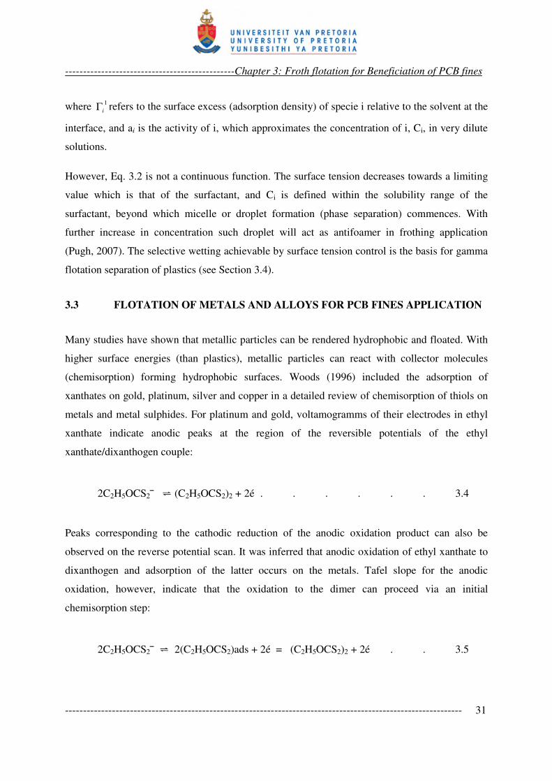
Lins and Adamian (1993) used amyl xanthate as a collector to study the effects of some physical
variables on gold flotation. Good recoveries were obtained for gold from a synthetic mixture of
silica and gold particles over 0.16 mm – 0.71 mm size ranges. About 90 % recovery and 5 kg/ton
gold grade in the float was achieved from a 167 g/ton feed with 0.16 mm dA sample at 18% pulp
density (Figure 3.1). The work of Lins and Adamian is notable considering the good flotation of
0.71 mm gold particles that was claimed.
Figure 3.1: Recovery and grade of gold in concentrate as a function of solids present and
gold size (mm): 3.6 lpm of air, 1200rpm, 167g Au/t feed (Lins and Adamian, 1993).
Dicresyl monothiophosphate (DCMTP) was used to achieve recovery of native gold against
sulphides at a pH above 7 in some specific ores (Nagaraj et al., 1991). Basilio et al. (1992)
PERCENT OF SOLIDS
-----------------------------------------------Chapter 3: Froth flotation for Beneficiation of PCB fines
-------------------------------------------------------------------------------------------------------------- 33
suggested that DCMTP does not have effect on the floatability of pure gold as such, and infra red
spectroscopic measurement confirming this. The improved gold recovery was linked to silver-
DCMTP interaction in further studies (Nagaraj et al., 1992). It was shown by X-ray
photoelectron spectroscopy (XPS) that more DCMTP was adsorbed, and higher recovery
observed, when the percentage of silver alloyed with the native gold was higher. Hence, only
silver-bearing native gold will respond to DCMTP. The interesting context here is that
adsorption on the alloy surface is synergistic. It can therefore be projected that alloys in the PCB
mixture will respond to a collector as much as one of its constituent elements interacts with that
collector.
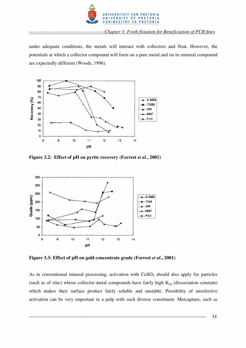
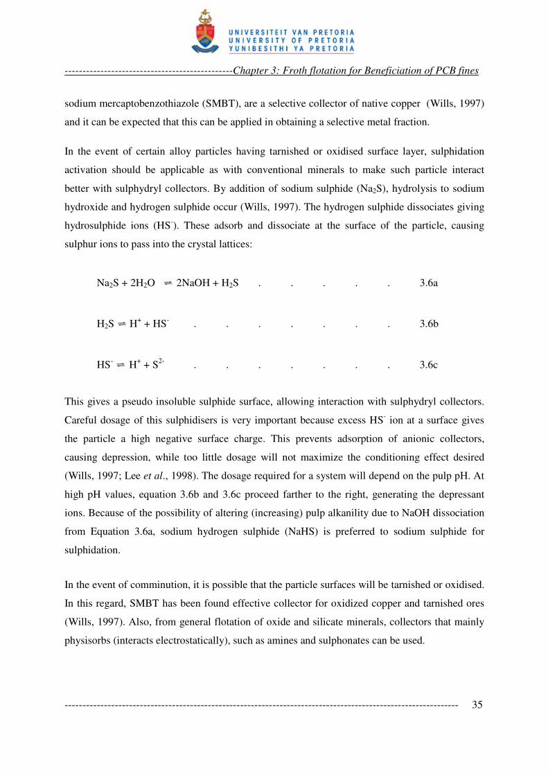
Forrest et al. (2001) using a range of collectors (Table 3.2) at varying pH on a free-gold bearing
copper-pyrite ore, obtained free gold recovery from the sulphides at d90 of 106 µm. While
chalcopyrite recovery was almost independent of pH in the range 8 – 13, and pyrite recovery
drop with increasing pH over the range (see Figure 3.2), gold grade shot up above pH 11.5
(Figure 3.3) for aeroflot 7249 and aeroflot 208. Selectivity for free gold by these collectors was
concluded for the gold grade increase at pH above 11.5, since pyrite was depressed and
chalcopyrite recovery remained almost the same over the pH range.
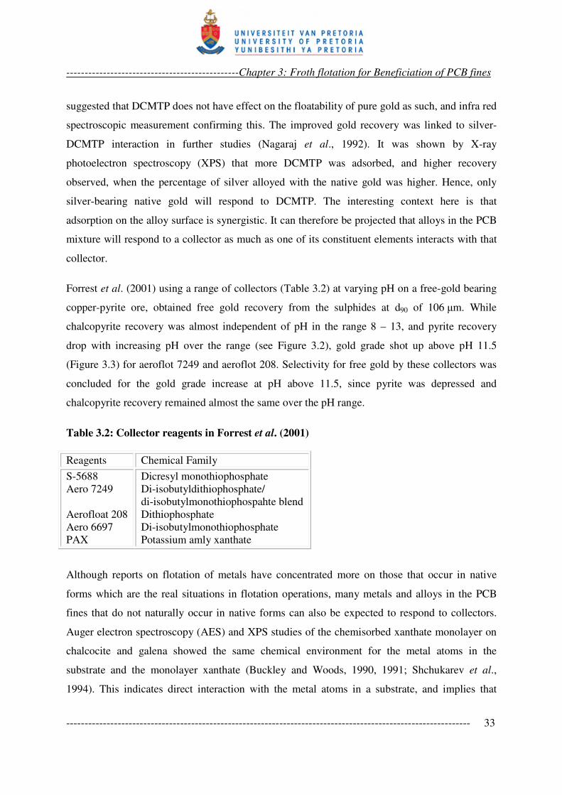
Table 3.2: Collector reagents in Forrest et al. (2001)
Reagents Chemical Family
S-5688
Aero 7249
Aerofloat 208
Aero 6697
PAX
Dicresyl monothiophosphate
Di-isobutyldithiophosphate/
di-isobutylmonothiophospahte blend
Dithiophosphate
Di-isobutylmonothiophosphate
Potassium amly xanthate
Although reports on flotation of metals have concentrated more on those that occur in native
forms which are the real situations in flotation operations, many metals and alloys in the PCB
fines that do not naturally occur in native forms can also be expected to respond to collectors.
Auger electron spectroscopy (AES) and XPS studies of the chemisorbed xanthate monolayer on
chalcocite and galena showed the same chemical environment for the metal atoms in the
substrate and the monolayer xanthate (Buckley and Woods, 1990, 1991; Shchukarev et al.,
1994). This indicates direct interaction with the metal atoms in a substrate, and implies that
-----------------------------------------------Chapter 3: Froth flotation for Beneficiation of PCB fines
-------------------------------------------------------------------------------------------------------------- 34
under adequate conditions, the metals will interact with collectors and float. However, the
potentials at which a collector compound will form on a pure metal and on its mineral compound
are expectedly different (Woods, 1996).
Figure 3.2: Effect of pH on pyrite recovery (Forrest et al., 2001)
Figure 3.3: Effect of pH on gold concentrate grade (Forrest et al., 2001)
As in conventional mineral processing, activation with CuSO4 should also apply for particles
(such as of zinc) whose collector-metal compounds have fairly high Keq (dissociation constant)
which makes their surface product fairly soluble and unstable. Possibility of unselective
activation can be very important in a pulp with such diverse constituent. Mercaptans, such as
-----------------------------------------------Chapter 3: Froth flotation for Beneficiation of PCB fines
-------------------------------------------------------------------------------------------------------------- 35
sodium mercaptobenzothiazole (SMBT), are a selective collector of native copper (Wills, 1997)
and it can be expected that this can be applied in obtaining a selective metal fraction.
In the event of certain alloy particles having tarnished or oxidised surface layer, sulphidation
activation should be applicable as with conventional minerals to make such particle interact
better with sulphydryl collectors. By addition of sodium sulphide (Na2S), hydrolysis to sodium
hydroxide and hydrogen sulphide occur (Wills, 1997). The hydrogen sulphide dissociates giving
hydrosulphide ions (HS-). These adsorb and dissociate at the surface of the particle, causing
sulphur ions to pass into the crystal lattices:
Na2S + 2H2O � 2NaOH + H2S . . . . . 3.6a
H2S � H+ + HS
- . . . . . . . 3.6b
HS- � H
+ + S
2- . . . . . . . 3.6c
This gives a pseudo insoluble sulphide surface, allowing interaction with sulphydryl collectors.
Careful dosage of this sulphidisers is very important because excess HS- ion at a surface gives
the particle a high negative surface charge. This prevents adsorption of anionic collectors,
causing depression, while too little dosage will not maximize the conditioning effect desired
(Wills, 1997; Lee et al., 1998). The dosage required for a system will depend on the pulp pH. At
high pH values, equation 3.6b and 3.6c proceed farther to the right, generating the depressant
ions. Because of the possibility of altering (increasing) pulp alkanility due to NaOH dissociation
from Equation 3.6a, sodium hydrogen sulphide (NaHS) is preferred to sodium sulphide for
sulphidation.
In the event of comminution, it is possible that the particle surfaces will be tarnished or oxidised.
In this regard, SMBT has been found effective collector for oxidized copper and tarnished ores
(Wills, 1997). Also, from general flotation of oxide and silicate minerals, collectors that mainly
physisorbs (interacts electrostatically), such as amines and sulphonates can be used.
-----------------------------------------------Chapter 3: Froth flotation for Beneficiation of PCB fines
-------------------------------------------------------------------------------------------------------------- 36
Flotation of glass fiber can also be conceived, considering the flotation of quartz from heamatite.
A reverse flotation of heamatite employs amine at pH 6-7. The amine adsorb on the negatively
charged quartz particle to float, leaving the heamatite particles that are relatively neutral at that
pH range (Fuerstanau and Healy, 1972).
Another approach floats quartz activated with calcium ion at pH 11-12 with a soap collector,
while using starch to depress heamatite. Soap application which can also have the effect of
gamma depression (see Section 3.5.2.4) is notable here, but isolating the activity or interactions
may not be easy in this very diverse material mixture: depression is already involved, and
influences on other particles exist. Interwoven and complicated reagent effects are not
unexpected in a sample of this type.
As addressed above, different collectors used with native metal and alloys, and tarnished ores, in
conventional minerals processing and in various investigations, can be expected to interact with
the metals and alloys in the PCB mixture – xanthates, amines, SMBT are all candidate collectors.
However, appropriate pH is critical to reagent-surface interaction.
3.3.1 Selectivity by pH Control
Pure water has a dissociation constant of 10–14
in which –log [OH–] = –log [H
+] = 7, the pH of
neutral water. The concentrations of OH– and H+ vary in proportion to maintain the equilibrium
constant at other pH values. In aqueous medium, OH– and H
+ are potential determining ions for
particles of oxide minerals and those with bases in their dissociation products, such as carbonates
(Kelly and Spottiswood, 1989). The pH of the medium therefore determines the surface charges
or neutrality (point of zero charge, or PZC) of the suspended particles. Response to ionic
collectors is a function of surface charge condition, and hence a function of pH. This is a basis of
selectivity by pH control.
Hydration of the surface and the stable surface species similarly depends on the pH. With iron,
for example, the Eh-pH diagram for Fe-O-H system indicates Fe(OH)3 as the stable specie for
most of the positive potentials at alkaline pH (see Figure 3.4). This frustrates formation of the
less stable metal-collector compound with xanthate collectors at high pH values. Pyrite, for
example, will therefore float under xanthate only at pH around 4 or below (Wills, 1997). With
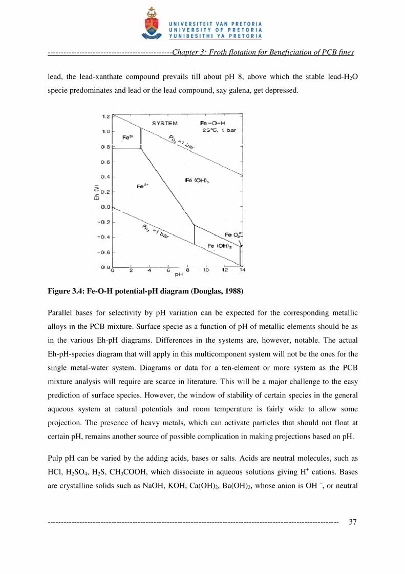
-----------------------------------------------Chapter 3: Froth flotation for Beneficiation of PCB fines
-------------------------------------------------------------------------------------------------------------- 37
lead, the lead-xanthate compound prevails till about pH 8, above which the stable lead-H2O
specie predominates and lead or the lead compound, say galena, get depressed.
Figure 3.4: Fe-O-H potential-pH diagram (Douglas, 1988)
Parallel bases for selectivity by pH variation can be expected for the corresponding metallic
alloys in the PCB mixture. Surface specie as a function of pH of metallic elements should be as
in the various Eh-pH diagrams. Differences in the systems are, however, notable. The actual
Eh-pH-species diagram that will apply in this multicomponent system will not be the ones for the
single metal-water system. Diagrams or data for a ten-element or more system as the PCB
mixture analysis will require are scarce in literature. This will be a major challenge to the easy
prediction of surface species. However, the window of stability of certain species in the general
aqueous system at natural potentials and room temperature is fairly wide to allow some
projection. The presence of heavy metals, which can activate particles that should not float at
certain pH, remains another source of possible complication in making projections based on pH.
Pulp pH can be varied by the adding acids, bases or salts. Acids are neutral molecules, such as
HCl, H2SO4, H2S, CH3COOH, which dissociate in aqueous solutions giving H+ cations. Bases
are crystalline solids such as NaOH, KOH, Ca(OH)2, Ba(OH)2, whose anion is OH –, or neutral
-----------------------------------------------Chapter 3: Froth flotation for Beneficiation of PCB fines
-------------------------------------------------------------------------------------------------------------- 38
molecules such as NH3, and CH3NH2 that forms proton acceptors and causes increase in the OH–
proportion, when dissolved in water. Salts are generally electrolytes whose ions are neither H+
nor OH–, but there are acid or basic salts whose aqueous solution is not neutral because they
cause proton concentration increase or decrease, respectively, on dissolution. NH4Cl, for
example, is an acid salt, with NH4+ cation, which is a proton donor in water:
+
4NH + H2O �NH3 + H3O+ . . . . . . . . 3.7
Also Na2CO3 in aqueous solution gives −2
3CO which is a weak base – a reluctant proton acceptor
in water:
−2
3CO + H2O� −
3HCO + OH– . . . . . . 3.8
In flotation practice, sulphuric acid [H2SO4] and lime [Ca(OH)2] are cheap and effective reagents
used to increase acidity and alkalinity, respectively, in pulps. When the depressant effect of lime
at high pH can be consequential, Na2CO3 is also used instead. Collector stability, as a function of
pH is also of importance in pH control and pH may not be varied unilaterally. In regulating pH
of PCB fines pulp with acids or bases, it is necessary to first establish the natural pulp pH and to
observe its stability with time. Varying pH with time, or buffering when trying to regulate the
fines pulp pH from the natural pH, is not impossible in such a complex mixture.
3.4 SELECTIVE WETTING OF PLASTICS FOR PCB FINES FLOTATION
APPLICATION: GAMMA FLOTATION
Plastics are naturally hydrophobic. Selective wetting to effect separation of plastics by flotation
has been demonstrated under four methods (Shent et al., 1999):
(i) physical conditioning, in which hydrophilic functionalities such as =O, –OH and –COOH,
are grafted into polymer chains at the surface usually by plasma treatment;
(ii) selective adsorption of wetting agents or chemical conditioning;
-----------------------------------------------Chapter 3: Froth flotation for Beneficiation of PCB fines
-------------------------------------------------------------------------------------------------------------- 39
(iii) selective hydrophobic modification, also a chemical conditioning, in which a surface
conditioning agent is selectively solubilised in the plastics so that it penetrate to a shallow
depth on the surface of some plastics; and
(iv) gamma flotation.
Gamma flotation is the most applied of the four methods and still best understood. It is based on
the critical surface tension of wetting of the solids (Buchan and Yarar, 1995), similar to the
original Zisman’s critical surface tension concept (Zisman, 1964) described by Alter (2005). The
critical surface tension of wetting for a solid (γC) is the minimum surface tension of a liquid that
will not wet the solid. That is, pure liquids or liquid solutions with surface tensions below this
value will wet the solid. Hence, by reducing the surface tension of a liquid (γLV), such as water,
to a value between the critical surface tension values of two plastic particles in a mix, say, γC1
and γC2, so that:
γC1 < γLV < γC2, . . . . . . . 3.9
the particles of the plastic with γC = γC2 become wetted, while the particles of the other plastic,
with γC = γC1, remain hydrophobic and float with air bubbles. Buchan and Yarar (1995), using
190 ppm methyl isobutyl carbinol (MIBC) as frother, 20 % methanol and 80 % H2O, achieved an
aqueous solution with surface tension of 40.8 dynes/cm, to effect the flotation separation of PVC
(γC = 39 dynes/cm) from PET (γC = 43 dyne/cm) which was wetted and sank. At the pulp density
of 1.0 % and pH 11, PET recovery to float was 0 %, while the recovery of PVC reached 92 %.
Shen et al. (2002) demonstrated the adsorption mechanism. Methyl cellulose was used for
selective chemical conditioning of the surface of seven plastics. Separation into three groups of
plastics was achieved. Van der Walls attraction-based physisorption between the numerous polar
groups in methyl cellulose and some of the plastics was used to explain the selective adsorption
and wetting, as the polar groups in some of the plastics were oriented towards the aqueous phase.
Surface tension effect was ruled out as methyl cellulose cannot reduce the surface tension of
water to the critical surface tension of wetting, γC, of the plastics wetted (see Figure 3.5). The
conclusions of the explanation may be debated given that a surface conditioning depressant
having hydrophobic non-polar group can as well impart flotation (Alter, 2005).
-----------------------------------------------Chapter 3: Froth flotation for Beneficiation of PCB fines
-------------------------------------------------------------------------------------------------------------- 40
The work by Fraunholcz et al. (1997a, 1997b) is an extensive fundamental research on plastics
flotation involving five classes of reagents, as shown in Table 3.3. The work concluded that the
effect of non-ionic surfactant on plastic wettability appears to be governed mainly by gamma
flotation. It stated further that the inorganic reagents did not affect plastic flotation, while the low
molecular weight complex compounds also do not adsorb sufficiently to effect depression.
Cations (including Na+, Ca
2+, Mg
2+, Fe
2+, Fe
3+ and H
+) were said to have significant effect on the
adsorption of the non-ionic weak acid and the anionic macromolecular depressants. Due to the
low reactivity of plastics, the influence of pH over the range of 5-12 on plastic flotation was
reported to be insignificant (Shibata et al., 1996).
For the plastics in PCB grinding mixture, non-ionic surfactants based gamma flotation appears
more straightforward and clearer to apply. The surface tension of the pulp is simply reduced
below the critical surface tension of wetting for some of the plastic constituents (see Table 2.3).
The non-ionic surfactants can also contribute to frothing. As it is necessary to be able to
delineate the effect of reagents addition in a sample, the other physical and chemical
conditioning methods are not straightforward for a complex mix of this sort. As mentioned, the
effects of ionic and weak acid macromolecular depressants depend on many cationic species in
the pulp. These effects will be difficult to isolate in a complex pulp such as the pulp of PCB
comminution fines, and can even impair flotation of the metallic values afterward.
Equations 3.2 and 3.3 indicate that selective wetting of the plastic particles requires careful
choice and dosage of the non-ionic surfactants. Some surfactant can depress surface tension so
much that the bulk becomes difficult to float. Also, the surfactant type should be such that
desired wetting is achieved with moderate dosage. In the work of Buchan and Yara (1995), 20 %
methanol in water was used to reduce the surface tension to 40.8 dyne/cm. This will represent a
significant reagent load and consumption. Moreover, the pulp density of 1.0 % used is too dilute
and reagent dosage may still shoot up at real industrial pulp densities. With methyl isobutyl
carbinol, MIBC, about 200 ppm reduces surface tension to 50 dynes/cm (Buchan and Yara,
1995). Figure 3.5 shows Tergitol 15-S-7 to be more effective in reducing the surface tension
below 35 dynes/cm at 20 ppm. Such can, therefore, be a better candidate reagent.
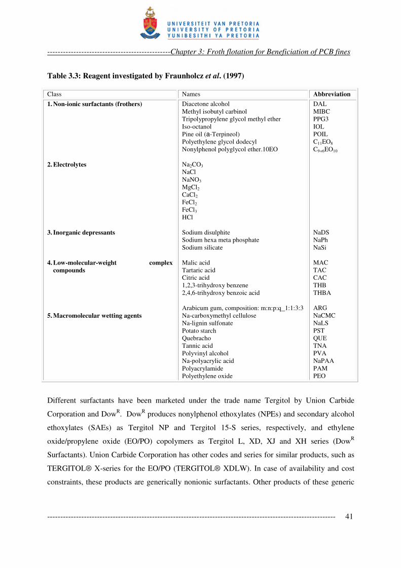
-----------------------------------------------Chapter 3: Froth flotation for Beneficiation of PCB fines
-------------------------------------------------------------------------------------------------------------- 41
Table 3.3: Reagent investigated by Fraunholcz et al. (1997)
Class Names Abbreviation
1. Non-ionic surfactants (frothers)
2. Electrolytes
3. Inorganic depressants
4. Low-molecular-weight complex
compounds
5. Macromolecular wetting agents
Diacetone alcohol
Methyl isobutyl carbinol
Tripolypropylene glycol methyl ether
Iso-octanol
Pine oil (a-Terpineol)
Polyethylene glycol dodecyl
Nonylphenol polyglycol ether.10EO
Na2CO3
NaCl
NaNO3
MgCl2
CaCl2
FeCl2
FeCl3
HCl
Sodium disulphite
Sodium hexa meta phosphate
Sodium silicate
Malic acid
Tartaric acid
Citric acid
1,2,3-trihydroxy benzene
2,4,6-trihydroxy benzoic acid
Arabicum gum, composition: m:n:p:q_1:1:3:3
Na-carboxymethyl cellulose
Na-lignin sulfonate
Potato starch
Quebracho
Tannic acid
Polyvinyl alcohol
Na-polyacrylic acid
Polyacrylamide
Polyethylene oxide
DAL
MIBC
PPG3
IOL
POIL
C11EO8
C9+6EO10
NaDS
NaPh
NaSi
MAC
TAC
CAC
THB
THBA
ARG
NaCMC
NaLS
PST
QUE
TNA
PVA
NaPAA
PAM
PEO
Different surfactants have been marketed under the trade name Tergitol by Union Carbide
Corporation and DowR. Dow
R produces nonylphenol ethoxylates (NPEs) and secondary alcohol
ethoxylates (SAEs) as Tergitol NP and Tergitol 15-S series, respectively, and ethylene
oxide/propylene oxide (EO/PO) copolymers as Tergitol L, XD, XJ and XH series (DowR
Surfactants). Union Carbide Corporation has other codes and series for similar products, such as
TERGITOL® X-series for the EO/PO (TERGITOL® XDLW). In case of availability and cost
constraints, these products are generically nonionic surfactants. Other products of these generic
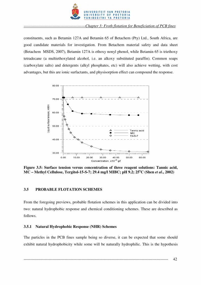
-----------------------------------------------Chapter 3: Froth flotation for Beneficiation of PCB fines
-------------------------------------------------------------------------------------------------------------- 42
constituents, such as Betamin 127A and Betamin 65 of Betachem (Pty) Ltd., South Africa, are
good candidate materials for investigation. From Betachem material safety and data sheet
(Betachem MSDS, 2007), Betamin 127A is ethoxy nonyl phenol, while Betamin 65 is triethoxy
tetradecane (a multiethoxylated alcohol, i.e. an alkoxy substituted paraffin). Common soaps
(carboxylate salts) and detergents (alkyl phosphates, etc) will also achieve wetting, with cost
advantages, but this are ionic surfactants, and physisorption effect can compound the response.
Figure 3.5: Surface tension versus concentration of three reagent solutions: Tannic acid,
MC – Methyl Cellulose, Tergitol-15-S-7; 29.4 mg/l MIBC; pH 9.2; 25oC (Shen et al., 2002)
3.5 PROBABLE FLOTATION SCHEMES
From the foregoing previews, probable flotation schemes in this application can be divided into
two: natural hydrophobic response and chemical conditioning schemes. These are described as
follows.
3.5.1 Natural Hydrophobic Response (NHR) Schemes
The particles in the PCB fines sample being so diverse, it can be expected that some should
exhibit natural hydrophobicity while some will be naturally hydrophilic. This is the hypothesis
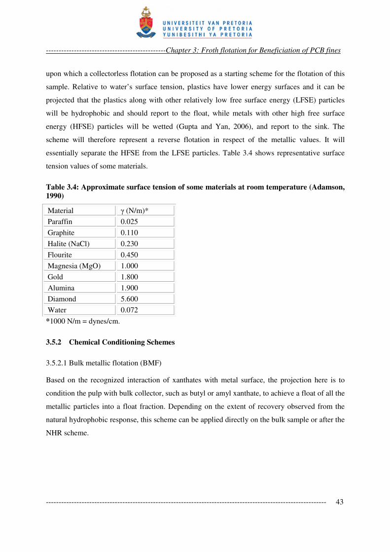
-----------------------------------------------Chapter 3: Froth flotation for Beneficiation of PCB fines
-------------------------------------------------------------------------------------------------------------- 43
upon which a collectorless flotation can be proposed as a starting scheme for the flotation of this
sample. Relative to water’s surface tension, plastics have lower energy surfaces and it can be
projected that the plastics along with other relatively low free surface energy (LFSE) particles
will be hydrophobic and should report to the float, while metals with other high free surface
energy (HFSE) particles will be wetted (Gupta and Yan, 2006), and report to the sink. The
scheme will therefore represent a reverse flotation in respect of the metallic values. It will
essentially separate the HFSE from the LFSE particles. Table 3.4 shows representative surface
tension values of some materials.
Table 3.4: Approximate surface tension of some materials at room temperature (Adamson,
1990)
Material γ (N/m)*
Paraffin 0.025
Graphite 0.110
Halite (NaCl) 0.230
Flourite 0.450
Magnesia (MgO) 1.000
Gold 1.800
Alumina 1.900
Diamond 5.600
Water 0.072
*1000 N/m = dynes/cm.
3.5.2 Chemical Conditioning Schemes
3.5.2.1 Bulk metallic flotation (BMF)
Based on the recognized interaction of xanthates with metal surface, the projection here is to
condition the pulp with bulk collector, such as butyl or amyl xanthate, to achieve a float of all the
metallic particles into a float fraction. Depending on the extent of recovery observed from the
natural hydrophobic response, this scheme can be applied directly on the bulk sample or after the
NHR scheme.
-----------------------------------------------Chapter 3: Froth flotation for Beneficiation of PCB fines
-------------------------------------------------------------------------------------------------------------- 44
3.5.2.2 Sulphidation activation
There is the possibility that metallic particles surfaces can be tarnished or oxidised in the event of
comminution. The extent of metallic response obtained from the bulk metallic flotation can be
indicative of this. In this case, sulfidation is a conceivable approach to activate such particles to
xanthates. Sulfidation is discussed in Section 3.3 and NaHS can be considered as the reagent of
choice.
3.5.2.3 Selective metallic flotation (SMF)
Depending on clarity of the response to reagent, some selective metallic flotation can be
projected based on reagents known to be selective of certain metallic values.
Mercaptobenzothiazole (MBT) is recognized as a selective collector in flotation of tarnished or
oxidized lead and copper minerals (Fuerstenau and Raghavan, 1986; Numata et al., 1998). The
copper and lead particles in the PCB comminution fines can also be conceived as tarnished (a
basis for sulfidation as explained above). The proportions of copper and lead in the PCB
comminution fines sample are relatively high. These are good rationales upon which to try
selective flotation with MBT. However, the selectivity will depend on the extent of the natural
hydrophobic response. This will determine the order of implementing the selective schemes. The
selective conditioning may have to be carried out on the sink of the NHR or on the float of the
bulk metallic flotation. Careful choice and use of depressant may also be needed to enhance the
selectivity. NHR particles, or residuals thereof, may need to be depressed to prevent
contamination of intended metallic fraction. Choice of depressant in this type of system will also
demand some careful experimentation.
3.5.2.4 Macromolecular and gamma depression
Achieving selectivity often demands selective depression. Generally, depressants selection takes
note of the particles in the system versus collector suite. In classical mineral processing,
chemical depressants such as cyanide and dichromate solubilise collector-particle surface
compound and frustrate air attachment (Wills, 1997). This will not regulate particles floating
under their natural hydrophobicity. Besides, the pulp here is complex enough and reagent
addition must be carefully regulated so that more active reagents are not added to the system if it
can be avoided.
-----------------------------------------------Chapter 3: Froth flotation for Beneficiation of PCB fines
-------------------------------------------------------------------------------------------------------------- 45
Organic macromolecular depressants, such as starch, tannin and quebracho are non-ionic and can
be regarded as less chemically reactive as they tend to smear and cover particles physically, as in
slime coating, to insulate them from reagent activation (Wills, 1997). Along this line, the
impression will be that these reagents will be bulk depressants. However, selective
chemisorption has been observed, such as in starch depression of heamatite from quartz activated
to soap collector by calcium ions at pH 11 – 12 (Fuerstenau and Fuerstenau, 1982). Without the
starch, heamatite would also float under this condition.
The work of Shent et al. (1999) mentioned in Section 3.4, showed the selective adsorption of
methyl cellulose (anionic) on some plastics. The explanation was based on physisorption by
Vander der wall attraction between the numerous polar groups in methyl cellulose and some of
the plastics. Broad acid-base interaction is becoming more convincing in explaining
polysaccharides adsorption (Laskowski et al., 2007). In depression of floatable carbonate and
silicate gangues in sulphide flotation, anionic organics, such as carboxymethyl cellulose (CMC)
are mostly used. Non-ionic ones are also used but high dosage levels are required, thereby
depressing the sulphide (Bulatovic, 1999). For possibility of effectiveness at moderate dosage,
without causing bulk depression, CMC can be considered as a probable macromolecular
depressant in this investigation.
From the idea of gamma flotation in plastics (Section 3.4), reduction in surface tension can be
used to achieve depression in the PCB comminution fines pulp. This surface tension (γ) based
depression concept can be succinctly described as gamma depression. By lowering the surface
tension of the pulp with appropriate surfactants, wetting becomes more favorable; the higher the
dosage, the lower the surface tension (Equation 3.2), and the higher the overall depression. This
will easily regulate natural hydrophobic flotation. For this purpose, non ionic surfactants (Table
3.2) can be used. This will give the advantage of no further addition of ions into the pulp.
Depression alternatives for the PCB comminution fine pulp may therefore be within these two
options – macromolecular and gamma depression.
Before this proposition is closed, gamma depression appears to oppose particle-bubble
attachment in the same pulp. Gamma depression requires reduction of surface tension of the
-----------------------------------------------Chapter 3: Froth flotation for Beneficiation of PCB fines
-------------------------------------------------------------------------------------------------------------- 46
aqueous medium to effect wetting of some of the particles, whereas bubble attachment is also
desired to effect flotation of some particles. The condition for wetting is:
SGSLLG γγγ <+ . . . . . . . . 3.10
The opposite is the condition for bubble attachment:
SGSLLG γγγ >+ . . . . . . . . 3.11
where, γLG, γSL and γSG are the liquid-gas, solid-liquid and solid-gas interfacial tensions.
It appears that lowering of the medium’s surface tension γLG to achieve wetting is to forfeit
bubble attachment, as it becomes difficult for the sum of γLG and γSL to exceed γSG again. Some
clarification is required to sustain the prospect of the projected process.
Plastics generally have low γSG, lower than that of water. This easily satisfies Equation 3.11, so
that they hardly wet. However, the magnitudes of γSG and γSL for plastics are such that
Equation 3.11 can be easily reversed by halving the γLG for water with surfactants. This will
satisfy the conditions of Equation 3.10.
For metallic particles and minerals, with much stronger interatomic bonds than plastics, the γSG
is orders of magnitude greater than γLG of water. Compare gold to water in Table 3.4 which
shows figures of surface tensions of some materials. Equation 3.10 is therefore easily satisfied
and they normally wet. The value of γLG for water is relatively insignificant in this case,
regulating it by the absence or presence of surfactant will not reverse Equation 3.10 to make such
particles hydrophobic. This is why hydrophobicity is imparted on high energy surfaces by
directly modifying such surfaces rather than the surface tension of the medium. This is what the
collectors do. By chemically reacting with the high energy surface, or electrostatically attaching
to it, a pseudo hydrocarbon surface is formed with γSG below that of the medium. This prevents
wetting.
The application to gamma depression is that bubble attachment will still occur as long as the
surfactant dosage does not lower γLG of the medium so much that it is impossible for the
-----------------------------------------------Chapter 3: Froth flotation for Beneficiation of PCB fines
-------------------------------------------------------------------------------------------------------------- 47
hydrophobic species adsorbed on the particles to meet the condition of equation 3.11. A useful
but scarce data to regulate the dosage will be surface tension values (γSG) of the surface-collector
species to allow a projection of the minimum γLG of the medium for a specific collector.
However, the non-polar hydrocarbon chains are hydrophobic. Hence, moderate reduction of γLG
of the pulp will still accommodate flotation of particles on which such surfactants are adsorbed,
or particles that are of sufficiently low surface tension values (γSG). Surfactants (collectors,
frothers) have always caused some reduction in medium surface tension, anyway. Yet, particle
bubble attachment still occurs in flotation pulps.
3.5.2.5 Cationic conditioning
At a given pH, particles in a pulp develop positive or negative charges or remain neutral (at their
point of zero charge). Cationic collectors can therefore be expected to achieve a bulk collection
based on surface charges, adsorbing on the negatively charged particles to float. This scheme can
be conceived in further beneficiation of the NHR sink. Generally physisorption-based
conditioning is considered not to be as selective as those based on chemisorption.
However, given the diversity of particles in this sample, any logical scheme is worth a trial. An
obvious variable here is the system pH, which can help improve selectivity. Amines are the
popular collector of choice, but with pH considered as a variable, the choice can be restricted to
quaternary amines. The fact is that the ionization of primary, secondary and tertiary amines
varies with pH so that the same dosage of this class of amines will show varying activity as pH
varies, thereby complicating the basis for comparing the response based on pH variation.
Quaternary amines, on the other hand, ionize completely at all pH values. Since the
hydrophobicity imparted by these heteropolar organic compounds increases with increasing
hydrocarbon chain length, the choice can be narrowed down to tetrabutlyammonium chloride,
with the long chain butyl groups.
3.6 APPLICABLE RANGE OF KINETIC PARAMETERS AND SAMPLE
CHARACTERISATION
The variety of the schemes presented underscores the unconventional flotation system this
sample will present. Flotation variables are many – kinetics, reagent types and dosages. In
-----------------------------------------------Chapter 3: Froth flotation for Beneficiation of PCB fines
-------------------------------------------------------------------------------------------------------------- 48
conventional mineral flotation investigations, there are known favorable operating regimes. This
helps to narrow down the variables. However, this usual range may not be invoked for this
application. Success of any of the schemes therefore depends on appropriate kinetics being
established first.
In flotation kinetics, the determinants of rate of particle removal by bubbles in a flotation cell
include gas flow rate, bubble diameter, cell volume, turbulence dissipation energy, fluid and
particle densities, kinematic viscosity, efficiency of collection (which consists of efficiency of
collision, attachment, and stability subprocesses), and of course the quantity of the particles to be
removed that are present at a time (Pyke et al., 2003).
Fortunately, these variables are not all mutually exclusive, so that not all these need to be
investigated. For a broad characterisation or description of the kinetic regime that will be
appropriate for this system and the projected schemes, it will suffice to use three basic
independent variables of air flow rate, impeller speed and pulp density. Other variables such as
bubble size, pulp viscosity, and turbulent dissipation energy are functions of these basic
variables. Other specific (material) characterisation that will be necessary here is in respect of
liberation and chemical composition analysis of the sample.
Particle liberation in PCB CF reported in literature can be summarized as very good; 100 %
below 600 µm, 500 µm, and 250 µm, as reported by various workers (Zhang and Forssberg,
1997; Wen et al., 2005; Zhao et al., 2004). The easy conclusion then is that -75 µm fraction will
consist of sole material particles. This arouses suspicion about the figures quoted in literature,
moreso that various authors differ. A basic liberation investigation of the fines will easily
confirm if liberation is total or not in the fines, and provides a working evidence in this
application. On the other hand, chemical composition characterisation is necessary to justify a
method of choice for assay analysis in this work.
Background fact here is that analytical procedure for this sample are lacking in standard
references (ASTM; ASTM, 2007; ISO). Studies and reviews have recommended and applied
various analytical techniques, such as XRF, XRD, FTIR, Raman spectroscopy,
thermogravimetry, wet assaying and fire assaying (Li et al 2004). While all of these techniques
may not be applicable to this sample, wet spectroscopic techniques appear to be quite relevant
-----------------------------------------------Chapter 3: Froth flotation for Beneficiation of PCB fines
-------------------------------------------------------------------------------------------------------------- 49
for the quantitative work that beneficiation recovery analyses demand. Assays from wet
techniques are known to depend on the extent of the recovery of the target constituent to the
leach liquor. Given the constitution of PCB fines, 100 % recovery of analytes may be difficult.
When little experience is available with respect to the digestion of a matrix, comparison of a
number of digestion techniques is recommended (Henryk, 2003). An investigation of
comparative digestion techniques can be informative for the assaying requirements in this
investigation.
3.7 INVESTIGATION OBJECTIVES
From the foregoing discourse, specific objectives towards this investigation are to:
i. Carry out qualitative liberation analysis of the −75 µm PCB comminution fines to
establish if the constituent particles are sole material particles or if composite
particles still persist at this size range of PCB comminution product.
ii. Carry out comparative wet digestion analysis to establish the effect of relevant
digestion techniques on the wet assay values of PCB comminution fines.
iii. Carry out trial and full experiments to establish favourable range of flotation kinetic
parameters applicable in the prospect of PCB comminution fines flotation.
iv. Investigate applicability of flotation for the beneficiation of PCB comminution fines
by employing logically probable flotation schemes that are based on expected
differences in natural hydrophobicity of particles in the fines sample and on responses
to certain chemical conditioning.
Essentially, the third objective must be pursued simultaneously with the fourth as the kinetics
must be observed under a scheme. This is the rationale for the preliminary trials, which will have
to set out from uncertain kinetic regime under unproven scheme. Some ancillary investigations
that may ensue in the course of these investigations, towards understanding the behaviour of the
system better, will be attended to, while not deviating too much from the set objectives.
In summary, the investigation will offer material and kinetic characterisation insights relevant to
PCB CF flotation prospects. It will establish how the sample responds to the reasonable flotation
schemes based on general froth flotation understanding. It will surely provide a basis for pursing

-----------------------------------------------Chapter 3: Froth flotation for Beneficiation of PCB fines
-------------------------------------------------------------------------------------------------------------- 50
further interests in this direction. Detailed work approach towards realising these objectives, as
well as secondary investigation objectives that ensued, are presented in the following chapter.