Embed Size (px)
Citation preview
Journal of Hydraulic Engineering 1 (2015) 47-59 doi: 10.17265/2332-8215/2015.01.005
A CFD Study on the Mechanisms Which Cause Cavitation in Positive Displacement Reciprocating
Pumps
Aldo Iannetti, Matthew T. Stickland and William M. Dempster
Department of Mechanical and Aerospace Engineering, University of Strathclyde, Glasgow G1 1XJ, UK
Abstract: A transient multiphase CFD (computational fluid dynamics) model was set up to investigate the main causes which lead to cavitation in PD (positive displacement) reciprocating pumps. Many authors agree on distinguishing two different types of cavitation affecting PD pumps: flow induced cavitation and cavitation due to expansion. The flow induced cavitation affects the zones of high fluid velocity and consequent low static pressure e.g. the valve-seat volume gap while the cavitation due to expansion can be detected in zones where the decompression effects are important e.g. in the vicinity of the plunger. This second factor is a distinctive feature of PD pumps since other devices such as centrifugal pumps are only affected by the flow induced type. Unlike what has been published in the technical literature to date, where analysis of positive displacement pumps are based exclusively on experimental or analytic methods, the work presented in this paper is based entirely on a CFD approach, it discusses the appearance and the dynamics of these two phenomena throughout an entire pumping cycle pointing out the potential of CFD techniques in studying the causes of cavitation and assessing the consequent loss of performance in positive displacement pumps. Key words: Multiphase flows, PD reciprocating pump, cavitation model, expansion cavitation, flow induced cavitation.
1. Introduction
The phenomenon of cavitation in pumps is still a complex problem to study. If one focuses on the sole category of PD reciprocating pumps one may say that there is a significant shortage of technical literature in this important area. Concentrating on the numerical analysis literature, very few works based on CFD on PD reciprocating pumps have been made so far, none of them deals with a comprehensive model of this kind of device operating in cavitation regimes. The main reason for the lack of studies dealing with the numerical analysis of cavitation dynamics in PD pumps is a consequence of the following reasons:
Over the last decades PD pumps have gradually become obsolete compared to centrifugal pumps on which great effort has been spent by researchers both in experimental and numerical analysis. This was
Corresponding author: Aldo Iannetti, master, main research field: fluid dynamics. E-mail: [email protected].
recalled by Herbert Tackett [2] who identifies the cause of the great popularity of centrifugal pumps due to the technological improvement made to the min the last decades. He also pointed out that, as a consequence, PD pumps nowadays may be considered a technically “old” device.
Despite their appearance PD pumps are a complex device to model and study particularly by means of CFD. This has led the few researchers involved in PD pumps studies to prefer experimental tests over numerical methods.
The experimental methods, which are the only techniques utilized so far, usually provide the analysts with all the difficulties related to how to take, from the test rigs, crucial information such as the pressure field, the production rate of water vapour and the loss of volumetric efficiency. Furthermore numerical methods have not been feasible for many years because of the great amount of computational resources that a complex model, such a pump in
D DAVID PUBLISHING
A CFD Study on the Mechanisms Which Cause Cavitation in Positive Displacement Reciprocating Pumps
48
cavitating condition, may need. Herbert Tackett [2] also explains that there are still many applications where PD pumps outperform centrifugal pumps which is the reason why, in the authors’ opinion, in the next few years a re-evaluation of this “old” device is to be expected. One of the reasons for the re-evaluation lies in the development of both HPC (high performance computational) systems and CFD techniques such as multiphase algorithms and moving meshes which provide the analysts with advanced numerical tools ready to be employed in the analysis of fluid dynamics in PD pumps despite their complexity, will be demonstrated in this paper.
The main feature successfully implemented in the model developed by the authors, which puts this work ahead of the previous work such as that carried out by Ragoth Singh [3], is the simultaneous coexistence of the following sub-models:
Compressibility of water. Even though water, in certain operative condition, may be considered incompressible there are periods within the pumping cycle when the inlet and outlet valve are both closed and the compressibility model is required to stabilize the simulation and fulfil the mass continuity equation.
The valve dynamics model. The inlet and outlet valves move following the pump chamber pressure field which in turn depends on the valves dynamics. To correctly model a PD pump it is crucial to provide the solver with a UDF (user defined function) which accounts for the two-way coupling between the valve dynamics and the pressure field. As stated by Stephen Price [4], cavitation strongly depends on the inertia characteristic of the valve.
Advanced cavitation model. The choice of the cavitation model is crucial to achieve reasonably accurate results in the case of full cavitation conditions because the analyst must account for the non-condensable gas mass fraction to predict pump performance deterioration in the cavitating conditions. As demonstrated by H. Ding [5] the amount of non-condensable gas dissolved in the water affects the
prediction of the minimum NPSH (net positive suction head) required in the inlet manifold to keep the volumetric efficiency loss above the generally accepted 3% as recalled by John Miller [6].
The important role of the non-condensable gasses in cavitation was also pointed out by Tillmann Baur [7] who carried out an experimental test to demonstrate the interaction of the gases dissolved in the water on the bubble dynamics.
Many authors such as Karsten Opitz [8] agree on the partitioning of the cavitation types into incipient (referred to as marginal cavitation), partial and full cavitation. They are characterized by different features as described in [8] and it is of crucial importance, for the designer, to know which cavitating condition the pump being designed will operate in. In the case of incipient or marginal cavitation, for instance, it is understood [1] that the number of bubbles and their distribution do not seem to be harmful to the pump and, avoiding any operating condition in this range, would result in a uneconomical device. In the case of partial to full cavitation the damage as well as the loss in performance may be extremely high and allowing the pump to operate at that condition would result in failures and loss of money.
The cavitation phenomenon in PD pumps appears to be different from the one occurring in centrifugal pumps. In the latter case cavitation is related to the low pressure induced by the high velocity which affects the rotor at certain operational conditions (flow induced cavitation) while, in the case of PD pumps, cavitation may depend on the low static pressure due to the plunger decompression at the beginning of the inlet stroke as well as on the high velocity that the flow through the inlet valve may experience. This was discussed by Karsten Opitz [1].
The work presented in this paper was based on a transient CFD model of a PD reciprocating plunger pump to investigate the cavitation dynamics in incipient to full cavitating conditions and discusses the rate of production/destruction of vapour in the vicinity
A CFD Study on the Mechanisms Which Cause Cavitation in Positive Displacement Reciprocating Pumps
49
of the plunger, where the flow velocity is small, and in the volume between the inlet valve and its seat where the velocities are high and the Bernoulli’s effect is important.
2. Material and Methods
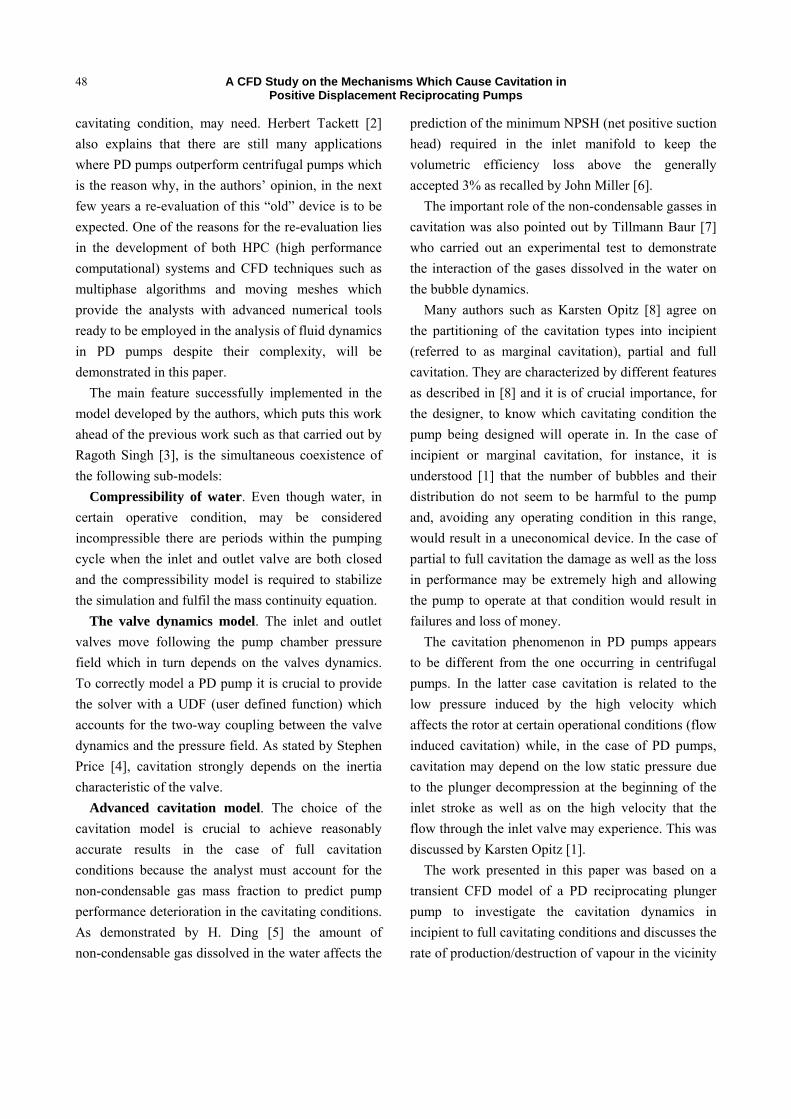
The transient CFD model simulated the entire pumping cycle; the induction stroke, from the TDC (top dead centre) position to when the plunger reached the BDC (bottom dead centre) position sweeping through the displacement volume, to the delivery stroke when the plunger again reached the TDC position as shown in Fig. 1, The overall pumping
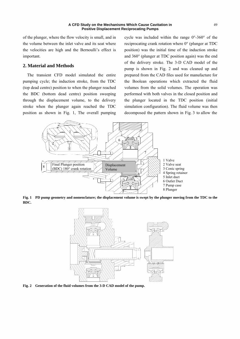
cycle was included within the range 0°-360° of the reciprocating crank rotation where 0° (plunger at TDC position) was the initial time of the induction stroke and 360° (plunger at TDC position again) was the end of the delivery stroke. The 3-D CAD model of the pump is shown in Fig. 2 and was cleaned up and prepared from the CAD files used for manufacture for the Boolean operations which extracted the fluid volumes from the solid volumes. The operation was performed with both valves in the closed position and the plunger located in the TDC position (initial simulation configuration). The fluid volume was then decomposed the pattern shown in Fig. 3 to allow the
Fig. 1 PD pump geometry and nomenclature; the displacement volume is swept by the plunger moving from the TDC to the BDC.
Fig. 2 Generation of the fluid volumes from the 3-D CAD model of the pump.
1 Valve 2 Valve seat 3 Conic spring 4 Spring retainer 5 Inlet duct 6 Outlet Duct 7 Pump case 8 Plunger
8
7
3
Final Plunger position (BDC) 180° crank rotation
Displacement Volume
6
5
4
2
3
1
A CFD Study on the Mechanisms Which Cause Cavitation in Positive Displacement Reciprocating Pumps
50
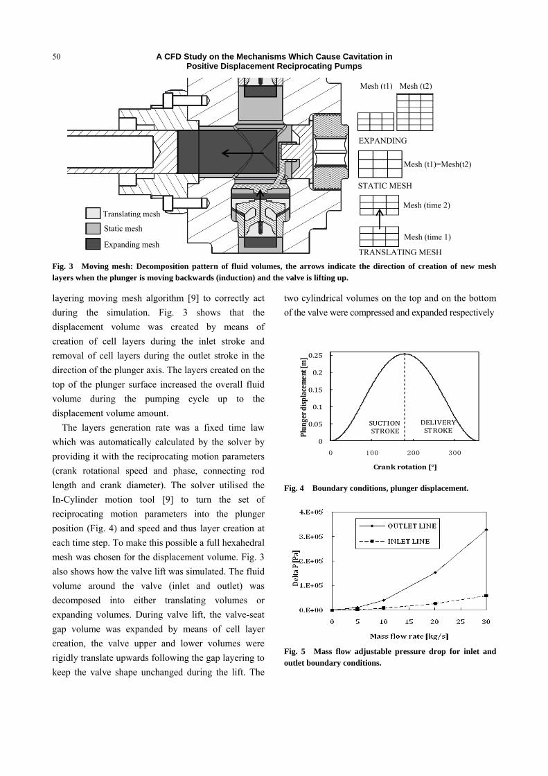
Fig. 3 Moving mesh: Decomposition pattern of fluid volumes, the arrows indicate the direction of creation of new mesh layers when the plunger is moving backwards (induction) and the valve is lifting up.
layering moving mesh algorithm [9] to correctly act during the simulation. Fig. 3 shows that the displacement volume was created by means of creation of cell layers during the inlet stroke and removal of cell layers during the outlet stroke in the direction of the plunger axis. The layers created on the top of the plunger surface increased the overall fluid volume during the pumping cycle up to the displacement volume amount.
The layers generation rate was a fixed time law which was automatically calculated by the solver by providing it with the reciprocating motion parameters (crank rotational speed and phase, connecting rod length and crank diameter). The solver utilised the In-Cylinder motion tool [9] to turn the set of reciprocating motion parameters into the plunger position (Fig. 4) and speed and thus layer creation at each time step. To make this possible a full hexahedral mesh was chosen for the displacement volume. Fig. 3 also shows how the valve lift was simulated. The fluid volume around the valve (inlet and outlet) was decomposed into either translating volumes or expanding volumes. During valve lift, the valve-seat gap volume was expanded by means of cell layer creation, the valve upper and lower volumes were rigidly translate upwards following the gap layering to keep the valve shape unchanged during the lift. The
two cylindrical volumes on the top and on the bottom of the valve were compressed and expanded respectively
0
0.05
0.1
0.15
0.2
0.25
0 100 200 300
Plunger displacem
ent [m]
Crank rotation [°]
SUCTIONSTROKE
DELIVERYSTROKE
Fig. 4 Boundary conditions, plunger displacement.
Fig. 5 Mass flow adjustable pressure drop for inlet and outlet boundary conditions.
Static mesh
Expanding mesh
Translating mesh
STATIC MESH
Mesh (t1)=Mesh(t2)
TRANSLATING MESH
Mesh (time 2)
Mesh (time 1)
EXPANDING
Mesh (t1) Mesh (t2)
A CFD Study on the Mechanisms Which Cause Cavitation in Positive Displacement Reciprocating Pumps
51
to keep the volume continuity and to interface with the pump chamber static volumes, and vice versa while the valve closed. It is clear that during the valve motion, although the mesh changes, there was no increase in the overall fluid volume due to the motion of the valve. To make the valve lift possible a full hexahedral mesh was chosen for all the expanding and contracting volumes as they were involved with the layering generation just like the plunger top surface.
All the expanding volumes, were either cylindrical or annular shaped to simplify the meshing process and to permit a full hexahedral mesh. The static volumes and the translating volumes did not have any mesh requirements and a tetrahedral mesh was chosen for them.
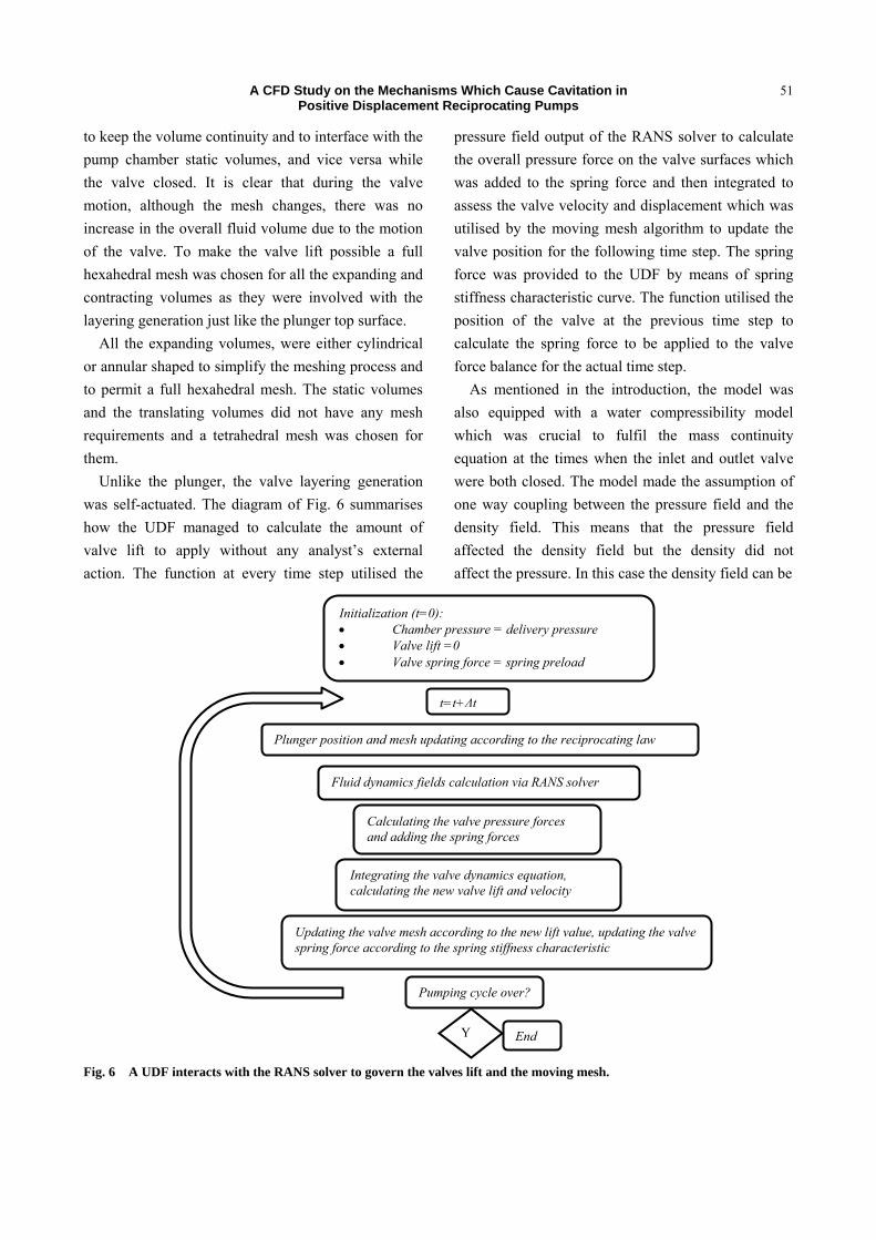
Unlike the plunger, the valve layering generation was self-actuated. The diagram of Fig. 6 summarises how the UDF managed to calculate the amount of valve lift to apply without any analyst’s external action. The function at every time step utilised the
pressure field output of the RANS solver to calculate the overall pressure force on the valve surfaces which was added to the spring force and then integrated to assess the valve velocity and displacement which was utilised by the moving mesh algorithm to update the valve position for the following time step. The spring force was provided to the UDF by means of spring stiffness characteristic curve. The function utilised the position of the valve at the previous time step to calculate the spring force to be applied to the valve force balance for the actual time step.
As mentioned in the introduction, the model was also equipped with a water compressibility model which was crucial to fulfil the mass continuity equation at the times when the inlet and outlet valve were both closed. The model made the assumption of one way coupling between the pressure field and the density field. This means that the pressure field affected the density field but the density did not affect the pressure. In this case the density field can be
Fig. 6 A UDF interacts with the RANS solver to govern the valves lift and the moving mesh.
Initialization (t=0): • Chamber pressure = delivery pressure • Valve lift =0 • Valve spring force = spring preload
t=t+Δt
Plunger position and mesh updating according to the reciprocating law
Fluid dynamics fields calculation via RANS solver
Calculating the valve pressure forces and adding the spring forces
Integrating the valve dynamics equation, calculating the new valve lift and velocity
Updating the valve mesh according to the new lift value, updating the valve spring force according to the spring stiffness characteristic
Pumping cycle over?
Y End
A CFD Study on the Mechanisms Which Cause Cavitation in Positive Displacement Reciprocating Pumps
52
calculated implicitly without linking the pressure and density via the energy equation. The assumption is reasonable when the working fluid is water.
The distinguishing feature and added sub-model which improved the model presented in this document from the one discussed in [10] is the multiphase and cavitation algorithm. A three phase model composed of water, water vapour and 15 ppm of non-condensable ideal gas was utilised as the working fluid. The water vapour fraction was initialised as null in all of the volumes and the Singhal et al. cavitation model managed the phase change dynamics according to the pressure field as explained in [11]. This cavitation model, also referred to as the “full” cavitation model, utilises a simple source term coming from the Rayleigh equation [12] by omitting the second-order derivative. It also accounts for the non-condensable gas effects already mentioned. A mass flow adjustable pressure was chosen as the boundary condition for the inlet and outlet pipe. Fig. 5 shows that the solver automatically chose the static
pressure to apply according to the mass flow rate calculated during the previous time step.
A mesh sensitivity analysis was carried out to define the best mesh size and spacing within the opposing needs of achieving good accuracy and keeping the computational time low. To this purpose three mesh sizes were tested; 3, 5 and 6 Million cells overall. The 5 M cells model was chosen because it proved the best results at a lower computational time than the 6 million cells case.
The ANSYS-Fluent commercial code was chosen to solve the RANS (reynolds averaged navier stokes) equations and Table 1 shows a summary of the settings selected. The UDF was written in C++ language. The standard k-ε model was chosen because it provided better convergence behaviour over other turbulence models such as the k-ω but the “enhanced wall treatment” [13] was needed to deal with the problem of the low y+. In fact, at times during the pumping motion, the minimum flow velocity was zero as the reciprocating motion of the plunger started from
Table 1 Solver settings.
Solver RANS, pressure based, transient
Models Multiphase
Mixture model [13]
Phases Water liquid Primary phase Water vapour Secondary phase
Turbulence K-ε Standard Enhanced wall treatment Cavitation Singhal et al. 15 ppm air (ideal gas)
Pressure-Velocity coupling SIMPLE
Spatial discretization
Momentum Second order upwind Vapour First order upwind Turbulent kinetic energy Second order upwind Turbulent dissipation rate Second order upwind
Transient formulation First order implicit
Under relaxation factors
Pressure 0.3 Momentum 0.7 Vapour 0.5 Turbulent kinetic energy 0.8 Turbulent dissipation rate 0.8
Residuals 10-3
Time step 0.125° crank rotation ≡ 1.6 x 10⁻⁴ s @130 rpm Max Iteration per time step 35
UDFs Compressibility of water [10] Valve dynamics,( Fig. 2)
A CFD Study on the Mechanisms Which Cause Cavitation in Positive Displacement Reciprocating Pumps
53
the TDC position, this necessitated the use of the “Enhanced wall treatment” which is capable of adjusting the standard wall functions in cases when (and where) the applicability of the standard wall function is no longer reasonable (y+<100). A 12 GB RAM computer with an Intel Xeon W3670 @ 3.2GHz processor was employed for the simulation and the time needed for a single run (1 pumping cycle only) ranged from 3 to 4 weeks. A set of four cases dealing with four different boundary conditions in term of pressure inlet/outlet was launched. All cases assumed the flow to be isothermal and therefore the equation of energy conservation was neglected.
The amount of non-condensable gas considered in the flow and listed in Table 1 behaved as ideal gas and its temperature variation under the overall pressure field was neglected. For all cases the inlet and outlet pressure were set as the sum of a constant value, ranging from 0 kPa to 100 kPa (depending on the case) and a transient value depending on the mass flow which was automatically calculated every time step by the solver. This added transient term took into account the distributed and concentrated pressure loss of the inlet and outlet pipelines. The reason for this added pressure drop term lies in the fact that the pressure loss is usually a characteristic curve of the pipe geometry which was not entirely modelled. As the boundary condition influence was not under investigation, the authors decided to fix the curve to the one shown in Fig. 5 which was fed into the solver by means of a piecewise linear law. Table 2 summarizes the four pressure boundary conditions for the four cases studied. A displacement-time law was chosen to drive the plunger and the moving mesh
attached to it as previously explained, in a manner similar to [10]. The displacement history over crank rotation is shown in Fig. 4.
3. Results and Discussion
3.1 Case 1
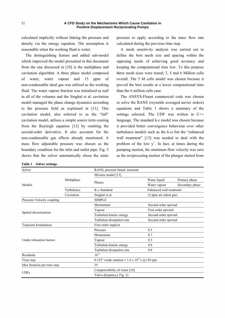
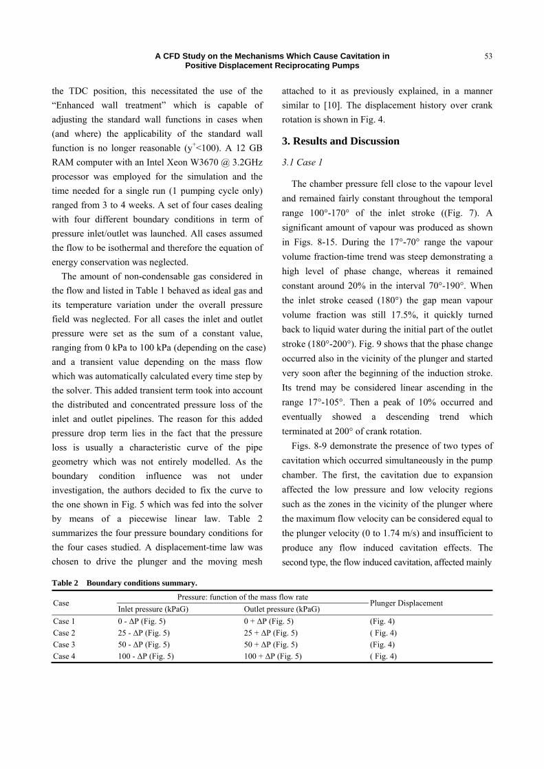
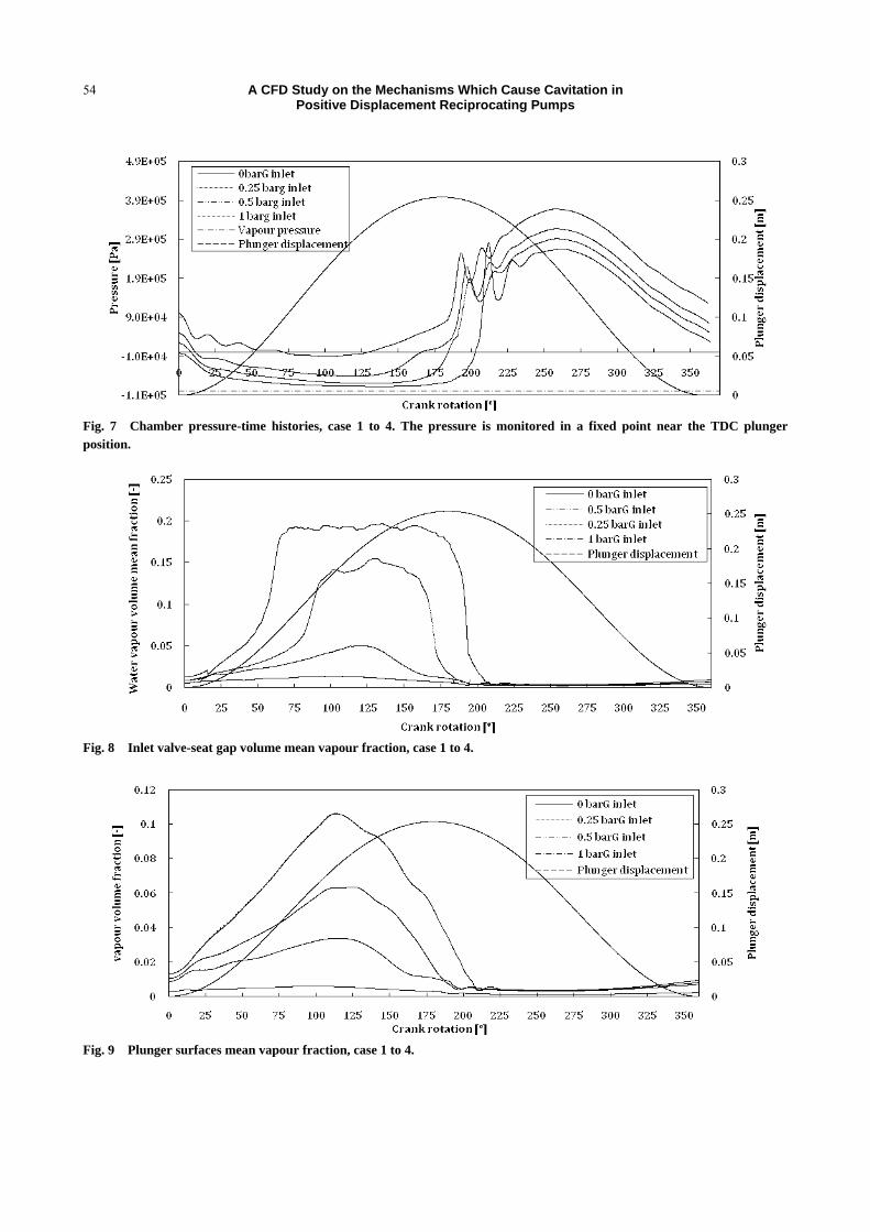
The chamber pressure fell close to the vapour level and remained fairly constant throughout the temporal range 100°-170° of the inlet stroke ((Fig. 7). A significant amount of vapour was produced as shown in Figs. 8-15. During the 17°-70° range the vapour volume fraction-time trend was steep demonstrating a high level of phase change, whereas it remained constant around 20% in the interval 70°-190°. When the inlet stroke ceased (180°) the gap mean vapour volume fraction was still 17.5%, it quickly turned back to liquid water during the initial part of the outlet stroke (180°-200°). Fig. 9 shows that the phase change occurred also in the vicinity of the plunger and started very soon after the beginning of the induction stroke. Its trend may be considered linear ascending in the range 17°-105°. Then a peak of 10% occurred and eventually showed a descending trend which terminated at 200° of crank rotation.
Figs. 8-9 demonstrate the presence of two types of cavitation which occurred simultaneously in the pump chamber. The first, the cavitation due to expansion affected the low pressure and low velocity regions such as the zones in the vicinity of the plunger where the maximum flow velocity can be considered equal to the plunger velocity (0 to 1.74 m/s) and insufficient to produce any flow induced cavitation effects. The second type, the flow induced cavitation, affected mainly
Table 2 Boundary conditions summary.
Case Pressure: function of the mass flow rate
Plunger Displacement Inlet pressure (kPaG) Outlet pressure (kPaG)
Case 1 0 - ΔP (Fig. 5) 0 + ΔP (Fig. 5) (Fig. 4) Case 2 25 - ΔP (Fig. 5) 25 + ΔP (Fig. 5) ( Fig. 4) Case 3 50 - ΔP (Fig. 5) 50 + ΔP (Fig. 5) (Fig. 4) Case 4 100 - ΔP (Fig. 5) 100 + ΔP (Fig. 5) ( Fig. 4)
A CFD Study on the Mechanisms Which Cause Cavitation in Positive Displacement Reciprocating Pumps
54
Fig. 7 Chamber pressure-time histories, case 1 to 4. The pressure is monitored in a fixed point near the TDC plunger position.
Fig. 8 Inlet valve-seat gap volume mean vapour fraction, case 1 to 4.
Fig. 9 Plunger surfaces mean vapour fraction, case 1 to 4.
A CFD Study on the Mechanisms Which Cause Cavitation in Positive Displacement Reciprocating Pumps
55
the zones experiencing a high velocity flow such as the inlet valve-seat volume once the valve lifted up. Fig. 8, which quantifies the amount of vapour volume fraction present in the inlet valve-seat gap volume, shows a non-linear trend and a higher rate with respect to Fig. 9, The rate of vapour fraction creation increased as the gap volume mean velocity and dynamic pressure increased (Figs. 10-11) and caused the pressure drop (Bernoulli’s effect). The delay in vapour condensation affected the inlet mass flow and the inlet valve lift histories as shown in Fig. 11 (a) and Fig. 12 (a). This effect is also shown in Table 3 which quantifies it as 205.3°, 25.3° in the early stage of the outlet stroke. Fig. 12 (b) shows the consequent delay in outlet valve opening which was the reason for the 7% loss of volumetric efficiency shown in Table 3. According to the described phenomena, one can assume that the pump was operating at full cavitating conditions in accordance with KarstenOpitz [1, 8]. Figs. 13-15 present the contour plots of pressure, velocity and vapour volume fraction respectively taken when the plunger reached 120° of rotation (just after the peak of vapour generation) and qualitatively confirm the numerical trend of Figs. 7-12.
3.2 Case 2
The chamber monitor point pressure during the induction stroke approached the saturation vapour pressure (Fig. 7). Fig. 8 shows a behaviour of the vapour fraction similar to case 1 but the maximum values estimated by the CFD solver were lower (15%) and remained almost constant over a narrower range (90°-165°). It can be observed from Fig. 9 that also, in the vicinity of the plunger, the vapour fraction follows a similar trend to case 1 with a smaller peak (6%) and a linear increase in the vapour volume fraction but at a lower rate. All the observations on the flow induced cavitation and cavitation due to expansion made for case 1 are qualitatively valid also for case 2. The smaller overall amount of vapour generated implied a smaller delay in valve closing which can be observed
in Fig. 12 (a). Table 3 quantifies the delay of 14.6° and a volumetric efficiency loss within the limit of 3% discussed by John Miller [6]. One can assume that case 2 describes a pump operating in the partial cavitating condition in accordance with Karsten Opitz [1, 8].
3.3 Case 3
Although the monitor pressure point in the chamber during the inlet stroke generally remained above the saturation vapour pressure (Fig. 7), a 5% peak of vapour fraction was present in the gap volume as shown in Fig. 8 and occurs at 120° of crank rotation. One may say that on the whole the pressure remained above the vapour limit but locally there were regions
Fig. 10 Inlet valve-seat gap volume mean flow velocity.
Fig. 11 Inlet valve-seat gap volume mean dynamic pressure.
Journal of Hydraulic Engineering 1 (2015) 47-59 doi: 10.17265/2332-8215/2015.01.005
(a) (b)
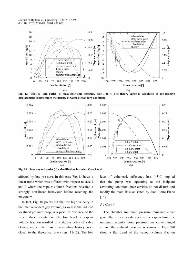
Fig. 12 Inlet (a) and outlet (b) mass flow-time histories, case 1 to 4. The theory curve is calculated as the positive displacement volume times the density of water at standard condition.
(a) (b)
Fig. 13 Inlet (a) and outlet (b) valve lift-time histories. Case 1 to 4.
affected by low pressure. In this case Fig. 8 shows a linear trend which was different with respect to case 1 and 2 where the vapour volume fractions revealed a strongly non-linear behaviour before reaching the maximum.
In fact, Fig. 10 points out that the high velocity in the inlet valve-seat gap volume, as well as the induced localized pressure drop, is a piece of evidence of the flow induced cavitation. The low level of vapour volume fraction resulted in a shorter delay of valve closing and an inlet mass flow rate/time history curve closer to the theoretical one (Figs. 11-12). The low
level of volumetric efficiency loss (<3%) implied that the pump was operating at the incipient cavitating condition since cavities do not disturb and modify the main flow as stated by Jean-Pierre Franc [14].
3.4 Case 4
The chamber minimum pressure remained either generally or locally safely above the vapour limit, the minimum monitor point pressure/time curve ranged around the ambient pressure as shown in Figs. 7-8 show a flat trend of the vapour volume fraction
A CFD Study on the Mechanisms Which Cause Cavitation in Positive Displacement Reciprocating Pumps
57
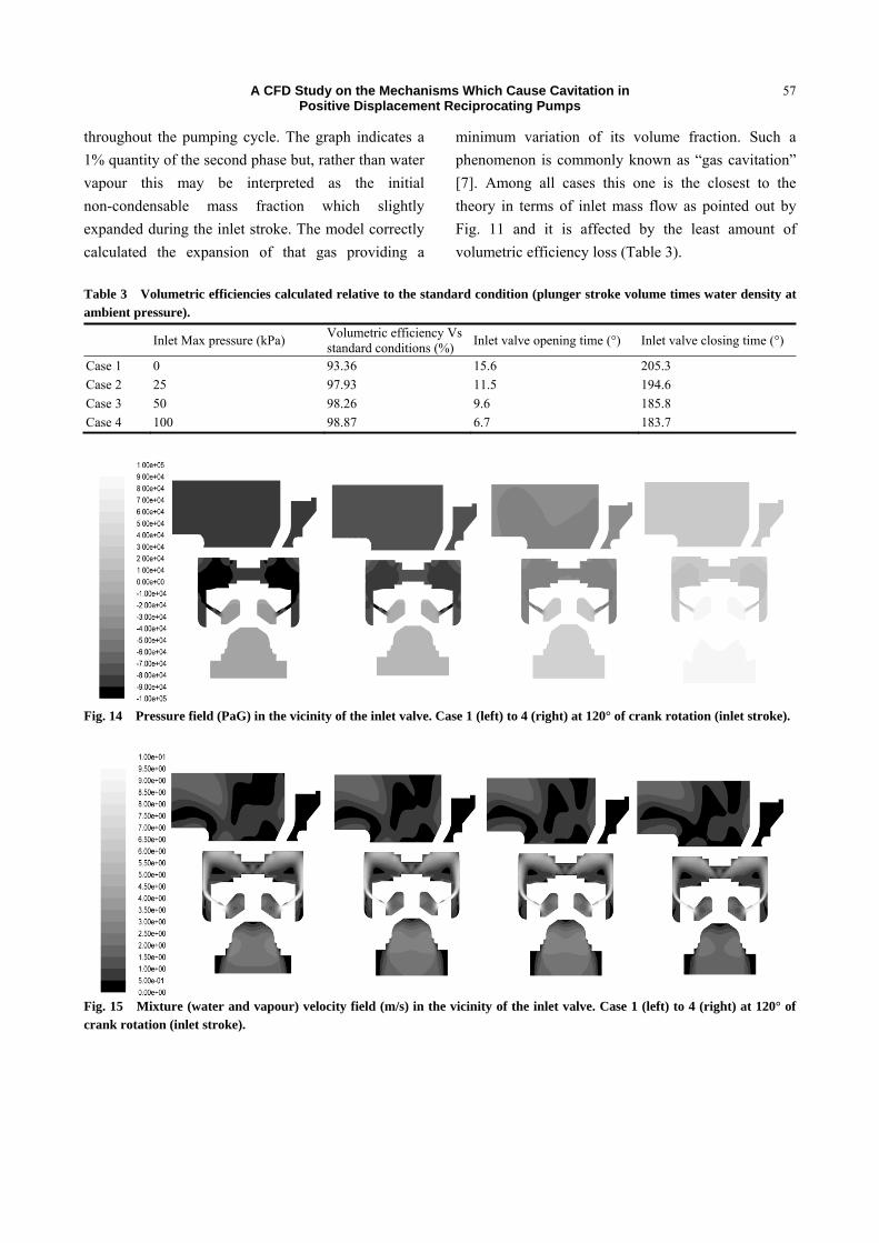
throughout the pumping cycle. The graph indicates a 1% quantity of the second phase but, rather than water vapour this may be interpreted as the initial non-condensable mass fraction which slightly expanded during the inlet stroke. The model correctly calculated the expansion of that gas providing a
minimum variation of its volume fraction. Such a phenomenon is commonly known as “gas cavitation” [7]. Among all cases this one is the closest to the theory in terms of inlet mass flow as pointed out by Fig. 11 and it is affected by the least amount of volumetric efficiency loss (Table 3).
Table 3 Volumetric efficiencies calculated relative to the standard condition (plunger stroke volume times water density at ambient pressure).
Inlet Max pressure (kPa) Volumetric efficiency Vs standard conditions (%) Inlet valve opening time (°) Inlet valve closing time (°)
Case 1 0 93.36 15.6 205.3 Case 2 25 97.93 11.5 194.6 Case 3 50 98.26 9.6 185.8 Case 4 100 98.87 6.7 183.7
Fig. 14 Pressure field (PaG) in the vicinity of the inlet valve. Case 1 (left) to 4 (right) at 120° of crank rotation (inlet stroke).
Fig. 15 Mixture (water and vapour) velocity field (m/s) in the vicinity of the inlet valve. Case 1 (left) to 4 (right) at 120° of crank rotation (inlet stroke).
A CFD Study on the Mechanisms Which Cause Cavitation in Positive Displacement Reciprocating Pumps
58
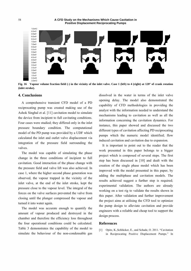
Fig. 16 Vapour volume fraction field (-) in the vicinity of the inlet valve. Case 1 (left) to 4 (right) at 120° of crank rotation (inlet stroke).
4. Conclusions
A comprehensive transient CFD model of a PD reciprocating pump was created making use of the Ashok Singhal et al. [11] cavitation model to simulate the device from incipient to full cavitating conditions. Four cases were studied; they differed only in the inlet pressure boundary condition. The computational model of the PD pump was provided by a UDF which calculated the inlet and outlet valve displacement via integration of the pressure field surrounding the valves.
The model was capable of simulating the phase change in the three conditions of incipient to full cavitation. Good interaction of the phase change with the pressure field and valve lift was also achieved. In case 1, where the higher second phase generation was observed, the vapour trapped in the vicinity of the inlet valve, at the end of the inlet stroke, kept the pressure close to the vapour level. The integral of the forces on the valve surfaces prevented the valve from closing until the plunger compressed the vapour and turned it into water again.
The model was accurate enough to quantify the amount of vapour produced and destroyed in the chamber and therefore the efficiency loss throughout the four operational conditions could be calculated. Table 3 demonstrates the capability of the model to simulate the behaviour of the non-condensable gas
dissolved in the water in terms of the inlet valve opening delay. The model also demonstrated the capability of CFD methodologies in providing the analyst with the information needed to understand the mechanisms leading to cavitation as well as all the information concerning the cavitation dynamics. For instance, this paper showed and discussed the two different types of cavitation affecting PD reciprocating pumps which the numeric model identified; flow induced cavitation and cavitation due to expansion.
It is important to point out to the reader that the work presented in this paper belongs to a bigger project which is composed of several steps. The first step has been discussed in [10] and dealt with the creation of the single phase model which has been improved with the model presented in this paper, by adding the multiphase and cavitation models. The results achieved suggest a further step is required; experimental validation. The authors are already working on a test rig to validate the results shown in this paper. After validation and further improvement the project aims at utilising the CFD tool to optimize the pump design to alleviate cavitation and provide engineers with a reliable and cheap tool to support the design process.
References [1] Opitz, K.,Schlücker, E., and Schade, O. 2011. “Cavitation
in Reciprocating Positive Displacement Pumps.” In
A CFD Study on the Mechanisms Which Cause Cavitation in Positive Displacement Reciprocating Pumps
59
Twenty-seventh International Pump Users Symposium, 27-33.
[2] Tackett, H. H., Cripe, J. A., and Dyson, G. 2008. “Positive Displacement Reciprocating Pump Fundamentals-Power and Direct Acting Types.” In Proceedings of the Twenty-fourth International Pump User Symposium, 45-58.
[3] Ragoth, R. S. and Nataraj, M. 2012. “Study on Performance of Plunger Pump at Various Crank Angle Using CFD.” IRACST Eng. Sci. Technol. An Int. J. (ESTIJ) 2 (4):549-53.
[4] Price, S. M., Smith, D. R., and Tison, J. D. 1995. “The Effects of Valve Dynamics on Reciprocating Pump.” In Proceedings of the Twelfth International Pump Users Symposium, 221-30.
[5] Ding, H., Visser, F. C. , and Jiang, Y. 2012. “A Practical Approach to Speed Up NPSHR Prediction of Centrifugal Pumps Using CFD Cavitation Model.” In Proceedings of the ASME 2012 Fluids Engineering Summer Meeting.
[6] Miller, J. E., ed. 1995. The Reciprocating Pump, Theory Design and Use. Malabar, FL (USA): Krieger publishing company.
[7] Baur, T., Köngeter, J., and Leucker, T. 1998. “Effects of
Dissolved Gas on Cavitation Inception in Free Surface Flows.” In Third International Symposium on Cavitation.
[8] Opitz, K. and Schlücker, E. 2010. “Detection of Cavitation Phenomena in Reciprocating Pumps Using a High-Speed Camera.” Chem. Eng. Technol. 33 (10):1610-4.
[9] ANSYS, “ANSYS FLUENT User’ s Guide,” vol. 15317, no. November. ANSYS Inc., 2011.
[10] Iannetti, A., Stickland, M. T., and Dempster, W. M. 2014. “A Computational Fluid Dynamics Model to Evaluate the Inlet Stroke Performance of A Positive Displacement Reciprocating Plunger Pump.” Proc. Inst. Mech. Eng. Part A J. Power Energy 228 (5): 574-84..
[11] Singhal, A. K., Athavale, M. M., Li, H., and Jiang, Y. 2002. “Mathematical Basis and Validation of the Full Cavitation Model.” J. Fluids Eng. 124 (3): 617.
[12] Lord, R. 1917. “VIII. On the Pressure Developed in a Liquid during the Collapse of a Spherical Cavity.” Philos. Mag. Ser. 6, 34 (200): 94-8.
[13] ANSYS, “ANSYS Fluent Theory Guide,” vol. 15317, no. November. ANSYS Fluent, 2011.
[14] Franc, J. O. and Michel, J. M. 2004. Fundamental of Cavitation. Dordrecht (NL): Kluwer Academic Publishers.


![eprints.lancs.ac.uk · buckets [13], and in the rotating runner [2, 5], as well as to analyzing specific flow mechanisms like cavitation [14]. In most cases, commercial CFD software](https://img.pdfslide.us/doc/110x75/5e6d606f043323099d002525/buckets-13-and-in-the-rotating-runner-2-5-as-well-as-to-analyzing-specific.jpg)