Embed Size (px)
Citation preview

4'x8' Chicken Run Plan
Designed for up to 8 chickens

Disclaimer The information provided here will show you how to build a shed. However, howtoplans.org does not claim that the recommended techniques are the only way to accomplish this task. It will be the responsibility of each customer to ensure the application of the correct construction methods and the use of the proper materials.
In addition to the selection of the materials, the customer will be responsible for such construction tasks as caulking, flashing, gluing, insulating, and nailing, and for adequate workmanship in the areas of installation, roofing and weatherproofing, as well as for any other skills that are beyond the control of the designer. The materials mentioned in the plans do not represent an endorsement or recommendation of any particular product.
The Responsibility of Users Despite our commitment to presenting accurate information, howtoplans.org is not liable for any errors or omissions appearing in the plans. Furthermore, howtoplans.org will not be liable for any consequential, special, incidental or indirect damages resulting from the use of this information. Our freedom from liability also extends to such issues as the loss of anticipated profits or business opportunities, and economic losses stemming from the use of howtoplans.org, regardless of whether there has been notification of such damage.
Liability Those who utilize the methods described on howtoplans.org will be responsible for their own actions. We are not liable for any injuries or property damage that may arise from the use of the information appearing on this website. If you decide to use these plans, you should use only quality materials and should always follow good safety practices. In the event that you are unable to complete the project on your own, you should contact a certified contractor to ensure that construction is completed in accordance with the highest standards.
Permissions It is important to understand that planning and permission issues are dependent upon local requirements. Users of these plans are responsible for complying with the appropriate statutes and regulations, and for the proper implementation of the plans or other construction information provided by howtoplans.org. The city or county office in your area should be able to provide you with the relevant information.
Copyright The text and illustrations that appear here are the exclusive property of howtoplans.org and are protected by federal copyright laws. The one-time use of the plans is limited to anyone who purchases them. The duplication, publication, sale or distribution of any portion of these plans without prior written consent from the original designer will be subject to the appropriate penalties for copyright infringement.
www.howtoplans.org | page 2

4' x 8' Chicken Run Material List
Site Preparation Unit Qty Size NoteConcrete Yd3 1Clay bricks pcs 75 3 5/8" x 2 1/4" x 8"
Main Frame Unit Qty Size NotePressure-Treated Lumber (3 1/2" x 3 1/2") pcs 3 3'-5" Top platePressure-Treated Lumber (3 1/2" x 3 1/2") pcs 3 3'-5" Bottom platePressure-Treated Lumber (3 1/2" x 3 1/2") pcs 4 6' StudsPressure-Treated Lumber (3 1/2" x 3 1/2") pcs 4 6'-3 1/2" StudsPressure-Treated Lumber (3 1/2" x 3 1/2") pcs 2 7'-5" Bottom platePressure-Treated Lumber (3 1/2" x 3 1/2") pcs 2 8' Top plate
Floor Frame Unit Qty Size NotePressure-Treated Lumber (3/4" x 3") pcs 2 2'-5" JoistPressure-Treated Lumber (1 1/2" x 3") pcs 3 2'-5" JoistPressure-Treated Lumber (3 1/2" x 3 1/2") pcs 2 2'-5" JoistPressure-Treated Lumber (3 1/2" x 3 1/2") pcs 2 3'-5" JoistPlywood (9/16") pcs 1 2'-5" x 3'-5" Floor plane
Left Wall Frame Unit Qty Size NotePressure-Treated Lumber (1 1/2" x 3 1/2") pcs 1 1'-2 1/2" Window HeaderPressure-Treated Lumber (1 1/2" x 3 1/2") pcs 1 1'-2 1/2" Rough SillPressure-Treated Lumber (1 1/2" x 3 1/2") pcs 2 4' Studs
Inner Wall Frame Unit Qty Size NotePressure-Treated Lumber (1 1/2" x 3 1/2") pcs 2 4' Studs
Back Wall Frame Unit Qty Size NotePressure-Treated Lumber (1 1/2" x 3 1/2") pcs 2 4' Studs
Right Wall Frame Unit Qty Size NotePressure-Treated Lumber (3 1/2" x 3 1/2") pcs 1 6' Stud
www.howtoplans.org | page 3

Coop's Roof Unit Qty Size NotePressure-Treated Board (3/4" x 3 1/4") pcs 8 1'-1 1/2" Rafters bayPressure-Treated Board (3/4" x 3 1/4") pcs 4 1'-3 3/4" Rafters bayPressure-Treated Board (3/4" x 3 1/2") pcs 2 8' FasciaPressure-Treated Board (3/4" x 5 1/2") pcs 1 8' Ridge boardPressure-Treated Lumber (1 1/2" x 3 1/2") pcs 6 4 1/2" Gable wall StudPressure-Treated Lumber (1 1/2" x 3 1/2") pcs 6 9 3/4" Gable wall StudPressure-Treated Lumber (1 1/2" x 3 1/2") pcs 4 3'-4" Collar tiePressure-Treated Lumber (1 1/2" x 3 1/2") pcs 14 2'-11" RaftersPlywood (9/16") pcs 2 3'-1 1/2' x 4'-1 1/2" Roof sheathingPlywood (9/16") pcs 2 3'-1 1/2' x 4'-6 1/2" Roof sheathingBuilding paper (#15) roll 1Asphalt shingles (250# per sq. min) ft2 60Metal drip edge ft 32
Front Wall Frame Unit Qty Size NotePressure-Treated Lumber (1 1/2" x 3 1/2") pcs 1 2'-5" Door Header
Left Wall Exterior Siding Unit Qty Size NotePressure-Treated Lumber (1/4" x 3/4") pcs 1 3'-7" Starter coursePressure-Treated Lumber (3/4" x 2 1/2") pcs 2 1'-2 1/2" TrimPressure-Treated Lumber (3/4" x 2 1/2") pcs 2 1'-7 1/2" TrimPressure-Treated Lumber (3/4" x 2 1/2") pcs 2 2'-3 3/4" TrimPressure-Treated Lumber (3/4" x 2 1/2") pcs 1 3'-7" TrimPressure-Treated Lumber (3/4" x 2 1/2") pcs 2 4'-9 3/4" TrimWood siding boards (1/2" x 6") ft2 16 3'-7" Siding
Inner Wall Exterior Siding Unit Qty Size NotePressure-Treated Lumber (1/4" x 3/4") pcs 1 3'-7" Starter coursePressure-Treated Lumber (3/4" x 3/4") pcs 2 1'-2 1/2" GirtPressure-Treated Lumber (3/4" x 2 1/2") pcs 2 1'-1" TrimPressure-Treated Lumber (3/4" x 2 1/2") pcs 1 1'-7 1/2" TrimPressure-Treated Lumber (3/4" x 2 1/2") pcs 1 3'-7" TrimPressure-Treated Lumber (3/4" x 2 1/2") pcs 2 4'-3 1/2" TrimWood siding boards (1/2" x 6") ft2 16 5'-5" SidingPlywood (9/16") pcs 1 1'-2 1/2" x 1'-6 1/4" Chickens’ entrance
Back Wall Exterior Siding Unit Qty Size NotePressure-Treated Lumber (1/4" x 3/4") pcs 1 2'-8 1/2" Starter coursePressure-Treated Lumber (3/4" x 2 1/2") pcs 2 4'-5 1/2" TrimPressure-Treated Lumber (3/4" x 2 1/2") pcs 1 2'-8 1/2" TrimWood siding boards (1/2" x 6") ft2 12 2'-8 1/2" Siding
Front Wall Exterior Siding Unit Qty Size NotePressure-Treated Lumber (3/4" x 3 1/2") pcs 2 2'-5" TrimPressure-Treated Lumber (3/4" x 4 1/4") pcs 2 4'-5 1/2' Trim
www.howtoplans.org | page 4

Coop's Door Unit Qty Size NotePressure-Treated Lumber (1/4" x 3/4") pcs 1 1'-11 3/4" Starter coursePressure-Treated Lumber (3/4" x 2 1/2") pcs 2 2'-4 3/4" TrimPressure-Treated Lumber (3/4" x 2 1/2") pcs 2 3'-5 1/4" TrimPressure-Treated Lumber (3/4" x 3 1/2") pcs 2 1'-9 3/4" GirtsPressure-Treated Lumber (3/4" x 3 1/2") pcs 2 3'-10 1/4" GirtsWood siding boards (1/2" x 6") ft2 8 1'-11 3/4" Siding
Aviary's Door & Walls Unit Qty Size NotePressure-Treated Lumber (2 1/2" x 2 1/2") pcs 2 1'-11 1/4" GirtsPressure-Treated Lumber (2 1/2" x 2 1/2") pcs 2 5'-11 3/4" GirtsPressure-Treated Lumber (2 1/2" x 2 1/2") pcs 1 5'-10 3/4" Cross braceWire mesh (1/4") ft2 115
Aviary's Stairs Unit Qty Size NotePressure-Treated Lumber (3/4" x 1 1/2") pcs 5 1'-7 1/2" StairsPressure-Treated Lumber (1 1/2" x 1 1/2") pcs 2 3' GirtsPressure-Treated Lumber (1 1/2" x 1 1/2") pcs 1 3'-5" Girt
Nesting Box Unit Qty Size NotePressure-Treated Lumber (3/4" x 3/4") pcs 8 1' GirtsPlywood (9/16") pcs 6 1' x 9" ShelvesPlywood (9/16") pcs 4 1' x 3'-1 1/4" Vertical partitionsPlywood (9/16") pcs 1 1' x 2'-5" Bottom platePlywood (9/16") pcs 1 1' x 2'-5" Top platePlywood (9/16") pcs 1 3'-2 1/4" x 2'-5" Backside plate
Coop's Roost Unit Qty Size NotePressure-Treated Lumber (3/4" x 3/4") pcs 4 2'-5" StairsPressure-Treated Lumber (3/4" x 1 1/2") pcs 2 2'-9 3/4" Girts
Fasteners & Hardware Unit Qty Size NoteDoor hinge (3") pcs 5Door pull (4") pcs 2Surface bolt (4") pcs 2Corner braces (4 1/2 “ x 4 1/2 “ x 1/2 “ ) pcs 40Galvanized nails (2") pcs 310Wood screws (1") pcs 400Wood screws (2") pcs 120Wood screws (3") pcs 180Wood screws (5") pcs 150
www.howtoplans.org | page 5

Recommended Tools
Pliers
Knife
Spirit level
Electric Screwdriver
Screwdriver
Hand Saw
Chisel
Spade
Measuring Tape
Drill
Hammer
Milling Machine
www.howtoplans.org | page 6

AA
3'-1 1/2" 4'-11 1/4"
2'6'-
1/2"
4'-1 1/2"8'-
1/2"
8'- 3/4"
8'-8"
8'- 1/
2"
4'
2'-4 1/2"
Size & Dimensions
front left
back right
www.howtoplans.org | page 7

1 '
2'-10"
1 ' 1'
6'-10"
1'
4'-10"
8'-10"
1'
Ground Works1.1 Clear the area where you want to build the shed and layout for the foundation. Use the below
illustration as a guide.
1.2 For the foundation, dig the trenches at least 1’ wide and 1’ deep.
STEP 1
www.howtoplans.org | page 8

8"
3'-2"
8"
4'-6"
8"
7'-2"
8"
8'-6"
Concrete foundation
Mortar
Bricks
Ground
Foundation Preparation2.1 Fill the trenches to ground level with concrete and let cure, or harden. Since curing times vary between brands, read the packaging for recommended curing times.
2.2 Once the concrete has cured, use standard-sized bricks and lay them across the foundation. You will need roughly 75 bricks for this step.
STEP 2
www.howtoplans.org | page 9

Assemble thе Main Frame3.1 Using 3 1/2“ x 3 1/2“ pressure-treated lumber, construct main frame using the drawing below as a reference. You will need two boards cut to 7'-5" and three board cut to 3'-5" that will be the bottom plates, four boards cut to 6'-3 1/2" and four boards cut to 6' that will be the studs, two boards cut to 8' and three boards cut to 3'-5" that will be top plates.
3.2 Use 4 1/2 “ x 4 1/2 “ x 1/2 “ corner braces and 8x1” wood screws to secure the corners (node A). Connect the beams with 2x5" wood screws.
3.3 Using a speed square or carpenter's square, check the corners to make sure they are 90°.
STEP 3
A ( 1 : 10 )
A
8'3'-5"
6'-3 1
/2"
6'
3'-5"7'-5"
3 1/2"
6'-7"
4'
2'-5"
2'-4 1/4"2'- 3/4"
3 1/2"
3 1/2"
3 1/2"3 1/2"
4 1/2" 4 1/2"
1 1/2"
4 1/2
"
4 1/2"
1 1/2"
www.howtoplans.org | page 10

B ( 0,09 : 1 ) B2'-5"
1'-8
1/2"
3'-5"
Framing the Floor4.1 Assemble the outer frame using 3 1/2“ x 3 1/2“ pressure-treated lumber. You will need two boards cut to 2'-5" and two boards cut to 3'-5" that will be the joists.
4.2 Assemble the inner frame using 3/4" x 3" and 1 1/2” x 3” pressure-treated lumber. You will need five boards cut to 2'-5" that will be the joist.
4.3 Use 4 1/2 “ x 4 1/2 “ x 1/2 “ corner braces and 8x1” wood screws to secure the corners ( node A on page 10). Connect the beams with and 2x5" wood screws.
4.4 Cut the recess for the chicken door in the inner bottom beam (node B on page 12).
4.5 Using a speed square or carpenter's square, check the corners to make sure they are 90°.
STEP 4
www.howtoplans.org | page 11

Floor joists arrangement ( 1 : 8 )
B ( 1 : 8 )
D-D ( 1 : 3 )
Floor girts arrangement
Floor girts arrangement
D
D
3/4"
7" 1 1/2" 10 1/2" 1 1/2" 10 1/2" 1 1/2" 7"
3/4"
3 1/2
"
3"
3/4" 3/4" 2"
3"1/
2"
3 1/2
"
3 1/2"
1'-1 1/4" 1'-2 1/2" 1'-1 1/4"
3'-5"
3 1/2
"
STEP 4
www.howtoplans.org | page 12

Assemble Left Wall Frame5.1 Using 1 1/2“ x 3 1/2“ pressure-treated lumber, construct wall frame using the drawing below as a reference. You will need two boards cut to 4' that will be the studs, two boards cut to 1'-2 1/2" that will be window header and rough sill.
5.2 Connect the beams with 3" and 5" wood screws.
5.3 Using a speed square or carpenter's square, check the corners to make sure they are 90°.
STEP 5
11 3/4" 1 1/2" 1'-2 1/2" 1 1/2" 11 3/4"
1'-3 1
/4"
1 1/2
"1'-
2 1/2
"1 1
/2"
1'-3 1
/4"
4'
www.howtoplans.org | page 13

11 3/4"1'-2 1/2"
11 3/4"
4'
1 1/2"
1 1/2"
Assemble Inner Wall Frame6.1 Using 1 1/2“ x 3 1/2“ pressure-treated lumber, construct wall frame using the drawing below as a reference. You will need two boards cut to 4' that will be the studs.
6.2 Connect the beams with 5" wood screws.
6.3 Using a speed square or carpenter's square, check the corners to make sure they are 90°.
STEP 6
www.howtoplans.org | page 14

7 3/4"
1 1/2"
10 1/2"
1 1/2"
7 3/4"
4'
Assemble Back Wall Frame7.1 Using 1 1/2“ x 3 1/2“ pressure-treated lumber, construct wall frame using the drawing below as a reference. You will need two boards cut to 4' that will be the studs.
7.2 Connect the beams with 5" wood screws.
7.3 Using a speed square or carpenter's square, check the corners to make sure they are 90°.
STEP 7
www.howtoplans.org | page 15

2'-4 1/2"
3 1/2"
9"
6'
Assemble thе Right Wall Frame8.1 Using 3 1/2“ x 3 1/2“ pressure-treated lumber, construct wall frame using the drawing below as a reference. You will need one board cut to 6' that will be the stud.
8.2 Use 4 1/2 “ x 4 1/2 “ x 1/2 “ corner brace and 8x1” wood screws to secure the corners (node A on page 10). Connect the beams with and 2x5" wood screws.
8.3 Using a speed square or carpenter's square, check the corners to make sure they are 90°.
STEP 8
www.howtoplans.org | page 16

1'-1 1/2"1'-1 1/2"
1'-1 1/2"1'-1 1/2"
1'-3 3/4"1'-3 3/4"
8'
Assemble the Roof Frame9.1 Using 1 1/2 “ x 3 1/2 “ pressure-treated lumber, cut fourteen rafters 2'-11" long according to the dimensions in Nodes E and F on page 18.
9.2 Using 1 1/2 “ x 3 1/2 “ pressure-treated lumber, cut four collar ties 3'-4" long according to the dimensions in Node F on page 18.
9.3 Using 3/4 “ x 5 1/2 “ pressure-treated board, cut the ridge board 8' long according the illustration below.
9.4 Connect the beams with 2x3" wood screws.
STEP 9
www.howtoplans.org | page 17

F ( 1 : 5 )
F
2"
2"
2'-11"
2"
2"
2'-11"3 1/2" 3 1/2"
3'-4"
2'-4"
6" 6"
3 1/2
"5 1
/4"
5 1/2"
3/4"
1 1/4
"
2"
5 3/4"
5"
30°
60°3 1/2"
E ( 1 : 10 )
STEP 9
www.howtoplans.org | page 18

Assemble the Gable Wall Studs10.1 Using 1 1/2 “ x 3 1/2 “ pressure-treated lumber, cut four front wall, four inner wall and four back wall gable studs as shown in the illustration below. You will need six boards cut to 4 1/2" and six boards cut to 9 3/4".
10.2 Cut the top edge of each stud to connect them with rafters (node G).
10.3 Connect the beams with 2x3" wood screws.
STEP 10
G ( 1 : 4 )
G
6 1/4" 7 1/2" 10 1/2" 7 1/2" 6 1/4"
4 1/2
"
9 3/4
"
1 1/2"
1 1/2" 1 1/2"
1 1/2"
1 1/2" 60°
www.howtoplans.org | page 19

H ( 1 : 9 )
J ( 1 : 9 )
H
J
1'-1 1/2"1'-1 1/2"
1'-1 1/2"1'-1 1/2"
1'-3 3/4"1'-3 3/4"
Assemble the Rafter Bays11.1 Cut eight rafter bays 1'-1 1/2" long using 3/4“ x 3 1/4“ pressure-treated board (node H on page 21).
11.2 Cut four rafter bays 1'-3 3/4" long using 3/4“ x 3 1/4“ pressure-treated board (node J on page 21).
11.3 Cut the top edge of each stud to connect them with rafters.
11.4 Connect the beams with 2x3" wood screws.
STEP 11
www.howtoplans.org | page 20

H ( 1 : 4 )
J ( 1 : 4 )
2 3/4
"1/
2"
3/4"
3 1/4
"
1'-1 1/2"
2 3/4
"1/
2"
3/4"
3 1/4
"
1'-3 3/4"
STEP 11
www.howtoplans.org | page 21

Assemble Front Wall Frame12.1 Using 1 1/2“ x 3 1/2“ pressure-treated lumber, install door header using the drawing below as a reference. You will need one board cut to 2'-5".
12.2 Connect the beams with 3" wood screws.
12.3 Using a speed square or carpenter's square, check the corners to make sure they are 90°.
STEP 12
www.howtoplans.org | page 22
2'-5"
1 1/2
"

2'-5"3'-5"
Install Plywood for the Floor13.1 Cut sheets of 9/16” plywood for the floor sheathing using the drawing below as a guide.
You will need one 2'-5" x 3'-5" sheet.
13.2 Secure the plywood with 2" wood screws.
STEP 13
www.howtoplans.org | page 23

3'-1 1
/2"
3'-1 1/2"
4'-1 1/2"
4'-6 1/2"
4'-6 1/2"
4'-1 1/2"
Install Plywood for the Roof14.1 Cut sheets of 9/16” plywood for the roof sheathing using the drawing below as a guide. You will need two 3'-1 1/2' x 4'-6 1/2" sheets and two 3'-1 1/2' x 4'-1 1/2" sheets.
14.2 Secure the plywood with 2" wood screws.
STEP 14
www.howtoplans.org | page 24

1 1/2"
1 1/2" 1 1/2"
1 1/2"
2'-3 3/4"2'-3 3/4"
4'-8 1
/2"
4'-9 3
/4"
2 1/2" 3'-7" 2 1/2"
1'-7 1/2"
2 1/2" 2 1/2"
2 1/2
"1'-
3 1/4
"2 1
/2"
1'-2 1
/2"
2 1/2
"
2 1/2" 2 1/2"
Installing the Exterior Siding to the Left Wall15.1 Use 3/4 “ x 2 1/2 “ pressure-treated lumber to cut and install the wall trims. Use the illustration below as a reference. You will need two boards cut to 2'-3 3/4", two boards cut to 4'-9 3/4" and one board cut to 3'-7".
15.2 Prepare and install starter course 3'-7" long from the pressure-treated lumber with cross section 1/4" x 3/4" (node K).
15.3 Install the exterior siding using 1/2 “ x 6” siding boards in accordance with the illustration below. Ensure to provide opening for window as shown in the illustration..
15.4 Prepare 1/4" wire mesh with dimensions 1'-6" x 1'6" and install it on the inner side of the frames with the help of industrial stapler.
15.5 Use 3/4 “ x 2 1/2 “ pressure-treated lumber to cut and install the window trims. You will need two boards cut to 1'-2 1/2" and two boards cut to 1'-7 1/2".
STEP 15
K ( 1 : 10 )
3/4"
1/4"
5 1/2"
4 1/2"
K
www.howtoplans.org | page 25

L
L
4'-3 1
/2"
2 1/2" 3'-7" 2 1/2"
2 1/2
"
2 1/2" 2 1/2"
1'-7 1/2"
1'-1"
2 1/2
"
5'-6"
30°
Installing the Exterior Siding to the Inner Wall16.1 Use 3/4 “ x 2 1/2 “ pressure-treated lumber to cut and install the wall trims. Use the illustration below as a reference. You will need two boards cut to 4'-3 1/2" and one board cut to 3'-7".
16.2 Prepare and install starter courses 3'-7" long from the pressure-treated lumber with cross section 1/4" x 3/4" (node K on page 25).
16.3 Install the exterior siding using 1/2 “ x 6” siding boards in accordance with the illustration below.
16.4 Ensure to provide opening for chicken entrance as shown in the illustration.
16.5 Use 3/4 “ x 2 1/2 “ pressure-treated lumber to cut and install the chicken entrance trims. You will need two boards cut to 1'-1" and one board cut to 1'-7 1/2".
STEP 16
www.howtoplans.org | page 26

2 1/2" 2'-8 1/2" 2 1/2"
4'-5 1
/2"
2 1/2
"
Installing the Exterior Siding to the Back Wall17.1 Use 3/4 “ x 2 1/2 “ pressure-treated lumber to cut and install the wall trims. Use the illustration below as a reference. You will need two boards cut to 4'-5 1/2" and one board cut to 2'-8 1/2".
17.2 Prepare and install starter course 2'-8 1/2" long from the pressure-treated lumber with cross section 1/4" x 3/4" (node K on page 25).
17.3 Install the exterior siding using 1/2 “ x 6” siding boards in accordance with the illustration below.
STEP 17
www.howtoplans.org | page 27
M-M ( 1 : 12 )
M
M
4 1/4" 2'-5" 4 1/4"
4'-5 1
/2"
3 1/2
"3'-
10 1/
2"3 1
/2"
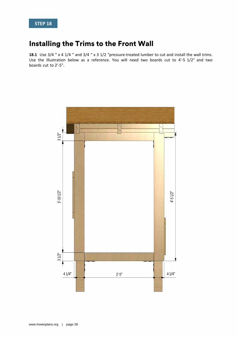
Installing the Trims to the Front Wall18.1 Use 3/4 “ x 4 1/4 “ and 3/4 “ x 3 1/2 “pressure-treated lumber to cut and install the wall trims. Use the illustration below as a reference. You will need two boards cut to 4'-5 1/2" and two boards cut to 2'-5".
STEP 18
www.howtoplans.org | page 28

N
P
Assemble and Install Coop's Door19.1 Build the door frame for the coop using 3/4 “ x 3 1/2 “ pressure-treated lumber and secure with 5” wood screws. You will need two boards cut to 3'-10 1/4" that will be the vertical girts and two boards cut to 1'-9 3/4" that will be the horizontal girts.
19.2 Use 3/4“ x 2 1/2 “ pressure-treated lumber for the door trims and fasten with 1” wood screws. You will need two boards cut to 2'-4 3/4" and two boards cut to 3'-5 1/4".
19.3 Using 1/4 “ x 3/4 “ pressure-treated lumber, cut and install a starter course 1'-11 3/4" long using Node K on page 25 as a reference.
19.4 For the exterior siding on the door, use 1/2 “ x 6” wood siding boards and the illustration below as a reference.
19.5 Assemble siding shields with 2" galvanized nails.
19.6 Install two 3" door hinges using 6x1" wood screws. Finish the doors installation by attaching 4" surface bolt and 6" door pull (see nodes N, P on page 30).
STEP 19
www.howtoplans.org | page 29

N ( 1 : 6 )
P ( 1 : 6 )
3 1/2"1'-9 3/4"
3 1/2"
3 1/2
"3 1
/2"
3'-10
1/4"
1'-11 3/4"
3'-6 3
/4"
2 1/2"
2 1/2"
2'-4 3/4"
2 1/2"
3'-5 1
/4"
2 1/2"
STEP 19
www.howtoplans.org | page 30

R
T
Assemble and Install Aviary's Door20.1 Build the door frame for the aviary using 2 1/2 “ x 2 1/2 “ pressure-treated lumber and secure with 5” wood screws. You will need two boards cut to 5'- 11 3/4" that will be the vertical girts, two boards cut to 1'-11 1/4" that will be the horizontal girts and one board cut to 5'-10 3/4" that will be a cross brace.
20.2 Prepare 1/4" wire mesh in the required quantity and install it on the inner side of the frame with the help of industrial stapler.
20.3 Install three 3" door hinges using 6x1" wood screws. Finish the doors installation by attaching 4" surface bolt and 6" door pull (see nodes R,T on page 32).
STEP 20
www.howtoplans.org | page 31

T ( 1 : 6 )R ( 1 : 6 )
6 1/2"
6 1/2"
5'-10 3/4"
2 1/2" 1'-11 1/4" 2 1/2"
2 1/2
"5'-
6 3/4
"2 1
/2"
2 1/2"
5'-11
3/4"
STEP 20
www.howtoplans.org | page 32

2'-5"2'-4 1/4"
2'- 3/4"
6'
1'-8 1
/2"
9"
6'
Aviary's Mesh Wall Installation23.1 Prepare 1/4" wire mesh in in the amount of 100 ft2 and install it on the innerside of the frames with the help of industrial stapler.
STEP 23
www.howtoplans.org | page 33

3'-1 1
/2"
3'-1 1/2"
8'-8"
Roof Sheathing Installation24.1 You will need 60 Sq Ft of asphalt shingle roofing.
24.2 Add the metal drip edge to the fascias.
24.3 Cover the plywood with building paper.
24.4 Install asphalt shingle roofing using an industrial stapler.
STEP 24
www.howtoplans.org | page 34

1'-7 1/2"
3'-5"
53° 3/4"
4 1/2" 3/4" 4 1/2" 3/4"4 1/2"
3/4"4 1/2"
3/4" 5"1 1/2" 1 1/2"
1"
1"
53°
3'
1 1/2" 1 1/2"
Aviary's Stairs Assembly25.1 Using 1 1/2“ x 1 1/2 “ pressure-treated material cut girt 3'-5" long and install as a support joist at the level of bottom frame according to the drawings below.
25.2 Using 1 1/2“ x 1 1/2 “ pressure-treated material, make the stairs frame using the illustration below as a guide and secure with 3” wood screws. You will need two boards cut to 3'. Cut the recesses in each beam for splicing connection.
25.3 For the stairs, you will need 3/4“ x 1 1/2" pressure-treated material. You will need five boards cut to 1'-7 1/2". Using the illustration as a reference, secure the stairs with 2” wood screws.
STEP 25
www.howtoplans.org | page 35

U-U ( 1 : 35 )U
1'-2 1/2"
Install Chicken Door In The Inner Wall26.1 Use 9/16” plywood to make a door for the chickens’ entrance. You will need one 1'-2 1/2" x 1'-6 1/4" sheet. Use the below drawing as a reference.
26.2 Using 3/4" x 3/4" pressure-treated lumber, construct groove for the door using the drawing below as a reference. You will need two boards cut to 1'-2 1/2" that will be the girts (see node W-W on page 37).
26.3 In the Step 4 you milled 1/2 “ deep section in the bottom beam that will help to secure the door and prevent them from being opened from the outside.
STEP 26
www.howtoplans.org | page 36

V-V ( 1 : 8 )
W-W ( 1 : 8 )
V
V
W
W1'-
6 1/4
"
1'-2 1/2"
3/4" 3/4" 3/4"
1/2"
1'-6 1
/4"
1/2"
1'
STEP 26
www.howtoplans.org | page 37

2'-5"
3'-2
1/4
"
1'- 9/16"
1'1'
1'
9"
9"9"
1'
Nesting Box Assembly27.1 Prepare the 9/16 plywood for horizontal and vertical walls and assembly them with 2" wood screws. You will need six 1' x 9" sheets that will be the shelves, four 3'-1 1/4" x 1' sheets that will be vertical partitions (see node X on page 39), one 2'-5" x 1' sheet that will be bottom plate, one 2'-5" x 1' sheet that will be top plate and one 3'-2 1/4" x 2'-5" that will be backside plate.
27.2 Use eight 3/4" x 3/4" pressure-treated lumber 1ft long for securing the shelves with partitions with the help of 1” wood screws.
STEP 27
www.howtoplans.org | page 38

1'2'-5"
2'-5"
3'-2 1
/4"
1'
3'-1 1
/4"
2'-5"1'
1' 9"9"
9"
1'
1'1'
X ( 1 : 8 )
STEP 27
www.howtoplans.org | page 39

2'-5"
1/4"
1/4"2'-9 3/4"
5 1/4"3/4"
7"3/4"
7"3/4"
7"3/4"
3"
3/4"3/4" 1 1/2"
Coop's Roost Assembly28.1 Using 3/4“ x 1 1/2 “ pressure-treated material, make the roost frame using the illustration below as a guide and secure with 3” wood screws. You will need two boards cut to 2'-9 3/4". Cut the recesses in each beam for splicing connection.
28.2 For the stairs, you will need 3/4 “ x 3/4“ pressure-treated material. You will need four boards cut to 2'-5". Using the illustration as a reference, secure the stairs with 2” wood screws.
STEP 28
www.howtoplans.org | page 40

Y ( 1 : 9 )
Y8'
3 1/2
"
3/4"
Assemble the Shed's Roof Fascias29.1 Prepare and install roof fascias 8' long from the pressure-treated board with cross section 3/4" x 3 1/2" with 16x2" wood screws to the rafters on both sides of the roof.
STEP 29
www.howtoplans.org | page 41

Coop DecorationNow that your coop is all done, you are ready to decorate it any way you want using your favorite paint, stain, or preservative.
STEP 30
Get SupportIf you have any questions or want to share the feedback, please do not hesitate contacting us:
https://www.howtoplans.org/contact/