Embed Size (px)
DESCRIPTION
Manufacturing Process – Metal Forming
Citation preview
Extrusion
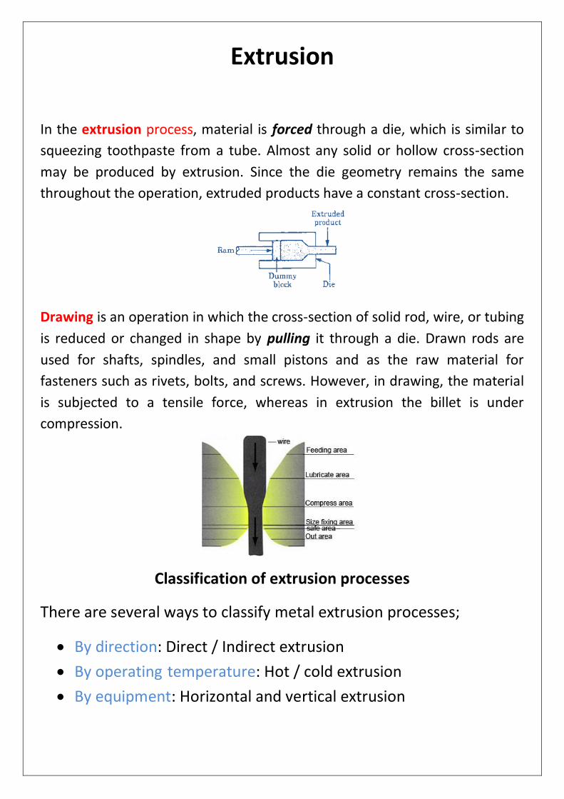
In the extrusion process, material is forced through a die, which is similar to
squeezing toothpaste from a tube. Almost any solid or hollow cross-section
may be produced by extrusion. Since the die geometry remains the same
throughout the operation, extruded products have a constant cross-section.
Drawing is an operation in which the cross-section of solid rod, wire, or tubing
is reduced or changed in shape by pulling it through a die. Drawn rods are
used for shafts, spindles, and small pistons and as the raw material for
fasteners such as rivets, bolts, and screws. However, in drawing, the material
is subjected to a tensile force, whereas in extrusion the billet is under
compression.
Classification of extrusion processes
There are several ways to classify metal extrusion processes;
By direction: Direct / Indirect extrusion
By operating temperature: Hot / cold extrusion
By equipment: Horizontal and vertical extrusion
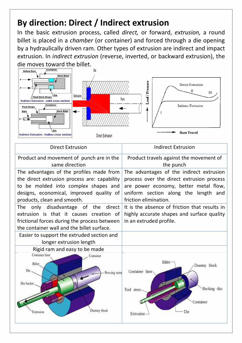
By direction: Direct / Indirect extrusion In the basic extrusion process, called direct, or forward, extrusion, a round billet is placed in a chamber (or container) and forced through a die opening by a hydraulically driven ram. Other types of extrusion are indirect and impact extrusion. In indirect extrusion (reverse, inverted, or backward extrusion), the die moves toward the billet.
Direct Extrusion Indirect Extrusion
Product and movement of punch are in the same direction
Product travels against the movement of the punch
The advantages of the profiles made from the direct extrusion process are: capability to be molded into complex shapes and designs, economical, improved quality of products, clean and smooth.
The advantages of the indirect extrusion process over the direct extrusion process are power economy, better metal flow, uniform section along the length and friction elimination.
The only disadvantage of the direct extrusion is that it causes creation of frictional forces during the process between the container wall and the billet surface.
It is the absence of friction that results in highly accurate shapes and surface quality in an extruded profile.
Easier to support the extruded section and longer extrusion length
Rigid ram and easy to be made
Extrusion equipment
Extrusion equipment mainly includes presses, dies and tooling.
1) Presses
Most extrusions are made with hydraulic presses.
These can be classified based on the direction of travel of the ram.
Horizontal presses
Vertical presses 2) Extrusion dies
3) Tools
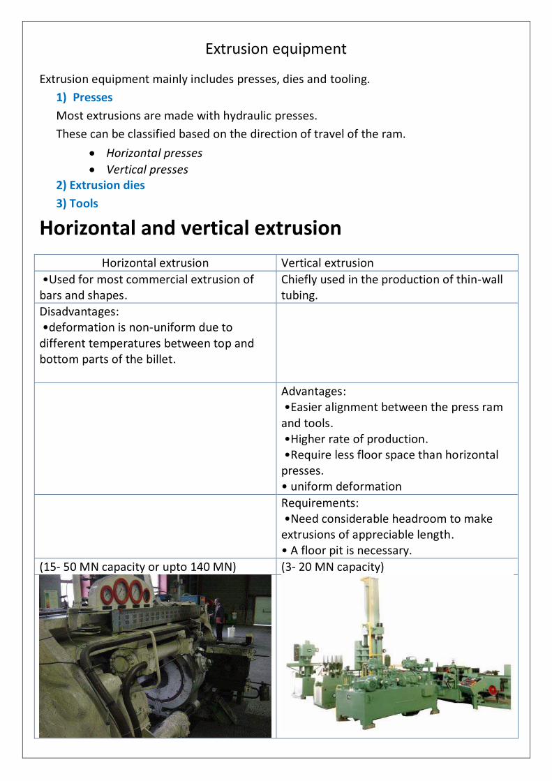
Horizontal and vertical extrusion
Horizontal extrusion Vertical extrusion
•Used for most commercial extrusion of bars and shapes.
Chiefly used in the production of thin-wall tubing.
Disadvantages: •deformation is non-uniform due to different temperatures between top and bottom parts of the billet.
Advantages: •Easier alignment between the press ram and tools. •Higher rate of production. •Require less floor space than horizontal presses. • uniform deformation
Requirements: •Need considerable headroom to make extrusions of appreciable length. • A floor pit is necessary.
(15- 50 MN capacity or upto 140 MN) (3- 20 MN capacity)
Extrusion Die and Wire Drawing Die:
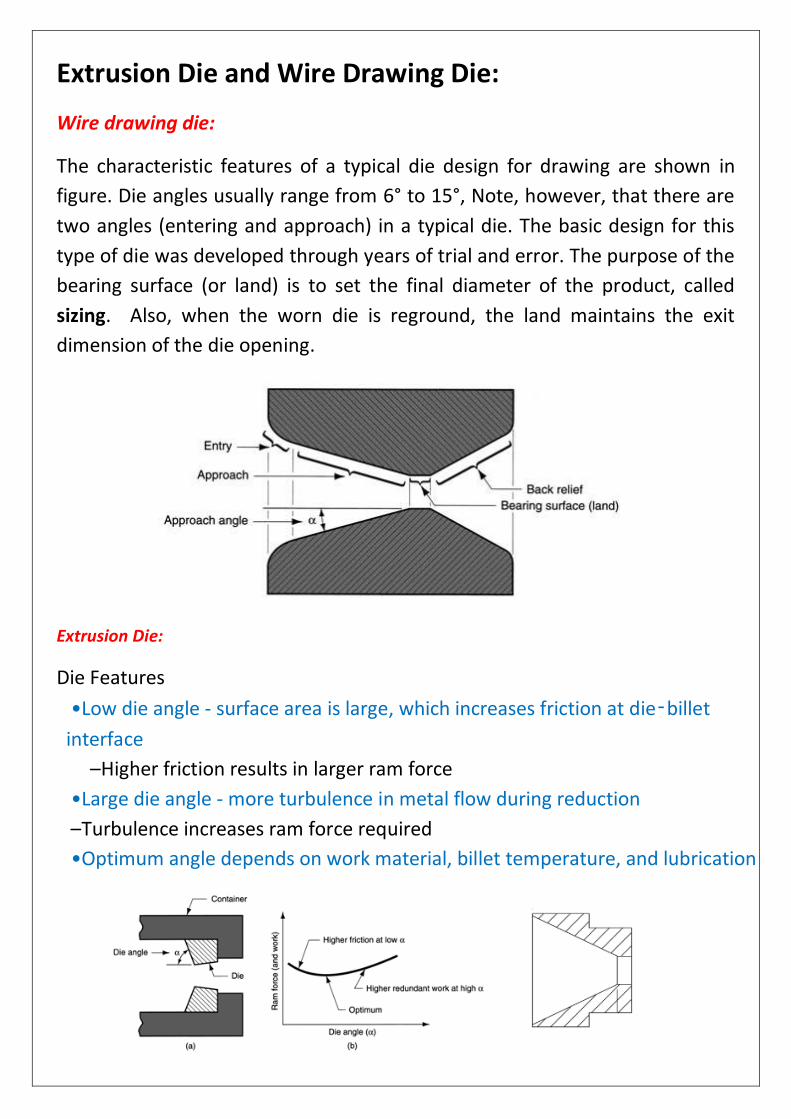
Wire drawing die:
The characteristic features of a typical die design for drawing are shown in
figure. Die angles usually range from 6° to 15°, Note, however, that there are
two angles (entering and approach) in a typical die. The basic design for this
type of die was developed through years of trial and error. The purpose of the
bearing surface (or land) is to set the final diameter of the product, called
sizing. Also, when the worn die is reground, the land maintains the exit
dimension of the die opening.
Extrusion Die:
Die Features
•Low die angle - surface area is large, which increases friction at die‑billet
interface
– Higher friction results in larger ram force
•Large die angle - more turbulence in metal flow during reduction
– Turbulence increases ram force required
•Optimum angle depends on work material, billet temperature, and lubrication
Effect of Principal Variables on Extrusion
Shape is a primary determining factor in the part's cost and ease with which it can be extruded. While a wide variety of shapes can be extruded, there are a number of interrelated limiting factors to be considered, including size, shape, alloy, extrusion ratio, tongue ratio, tolerance, finish, factor, and scrap ratio. If a part is beyond the limits of these factors, it cannot be extruded successfully. Other considerations include extrusion speed, temperature of the billet, extrusion pressure and the alloy being extruded. As a general rule, extrusion speed varies directly with metal temperature and pressure developed within the container. Temperature and pressure are limited by the alloy used and the shape being extruded. Lower extrusion temperatures will usually produce shapes with better quality surfaces and more accurate dimensions, but also require higher pressures. Sometimes, because of pressure limitations, a point is reached where it is impossible to extrude a shape through a given press.
Principal Variables The principal variables that influence the force required to cause extrusion and the quality of material exiting from the die are as follows:
Extrusion ratio
Working temperature
Speed of deformation
Alloy flow stress
Extrusion Ratio: The extrusion ratio (ER) of a multihole die is defined by:
𝐸𝑟 =𝐴𝑐
𝑛(𝐴𝐸)
Where n is the number of symmetrical holes, AC is the area of container, and AE is the area of extrusion. The extrusion ratio of a shape is a clear indication of the amount of mechanical working that will occur as the shape is extruded. The effective strain is a function of the extrusion ratio, and finally, extrusion pressure required to extrude is a function of strain. When the extrusion ratio of a profile is low, the amount of plastic strain is also low. As a result, the amount of work done during extrusion will be less. Extrusion Temperature: Extrusion is commonly classified as a hot-working process. Hot working is defined as deformation under conditions of temperature and strain-rate such that recovery processes take place simultaneously with deformation. Extrusion is carried out at elevated temperatures for metals and alloys that do not have sufficient plasticity range at room temperature and also to reduce the forces required for extrusion. Temperature is one of the most important parameters in extrusion. The flow stress is reduced if the temperature is increased and deformation is, therefore, easier, but at the same time, the maximum extrusion speed is reduced because localized temperature can lead to the
incipient melting temperature. The changes during extrusion depend on the billet temperature, the heat transfer from the billet to the container, and the heat developed by deformation and friction. In actual aluminum extrusion practice, very complex thermal changes commence as soon as the hot billet is loaded into the usually preheated container, and extrusion is started. Extrusion Speed: The response of a metal to extrusion processes can be influenced by the speed of deformation. Increasing the ram speed produces an increase in the extrusion pressure. The temperature developed in extrusion increases with increasing ram speed. This increase is due to the fact that the strain rate is directly proportional to the ram speed, and the magnitude of the generated heat is proportional to the strain rate. The slower the ram speed is, the more time will be available for the generated heat to flow. The heat conduction is more pronounced with aluminum because of its higher conductivity. Material Flow Stress: A true stress-strain curve is frequently called a flow curve because it gives the stress required to cause the metal to flow plastically to any given strain. The flow stress is important because in plastic deformation process, the forming load or stress is a function of part geometry, friction, and the flow stress of the deforming material. The flow stress of the material is influenced by the following factors:
• Chemistry and the metallurgical structure of the material • Temperature of deformation, the amount of deformation or strain and the rate of deformation or strain-rate
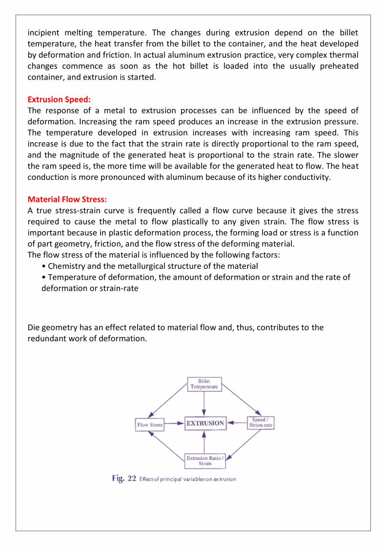
Die geometry has an effect related to material flow and, thus, contributes to the redundant work of deformation.
Plastic Deformation and Metal Flow In metal forming, plasticity theory is applied to investigate the mechanics of plastic deformation. The investigation allows the analysis and prediction of the following
Metal flow, including velocities, strain rates, and strain
Temperature and heat transfer
Variation of local material strength or flow stress of material
Stresses, forming load, pressure, and energy The mechanics of plastic deformation provide the means for determining how the metal flows in different forming operations, the means of obtaining desired geometry through plastic deformation, and the means for determining the expected mechanical and physical properties of the metal produced. Different mathematical equations can be obtained through a different approach for different forming operations, including extrusion. In simple homogeneous (uniaxial) compression or in tension, the metal flows plastically when the stress, σ, reaches the value of flow stress, 𝜎. The flow of aluminum during extrusion is intermetallic shear flow. The significant difference in the shear flow of aluminum compared with other metals being extruded is that the center of the aluminum billet is extruded first, and the peripheral part of the billet flows later, causing more severe shear deformation. As soon as the force required to push the billet into the container surface exceeds that of the shear strength of the billet material, sticking friction predominates, and deformation proceeds by shear in the bulk of the billet. Metal flow during extrusion depends on many factors, such as the following:
•Billet material property at billet temperature •Billet-container interface and metal-die interface friction • Extrusion ratio
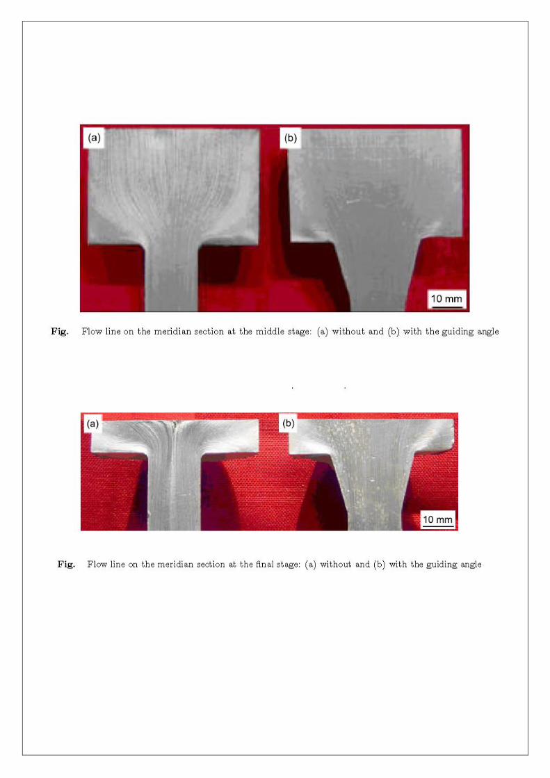
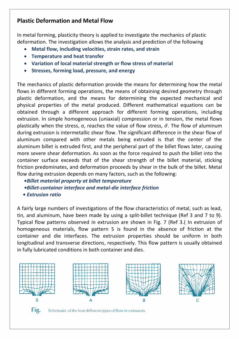
A fairly large numbers of investigations of the flow characteristics of metal, such as lead, tin, and aluminum, have been made by using a split-billet technique (Ref 3 and 7 to 9). Typical flow patterns observed in extrusion are shown in Fig. 7 (Ref 3.) In extrusion of homogeneous materials, flow pattern S is found in the absence of friction at the container and die interfaces. The extrusion properties should be uniform in both longitudinal and transverse directions, respectively. This flow pattern is usually obtained in fully lubricated conditions in both container and dies.
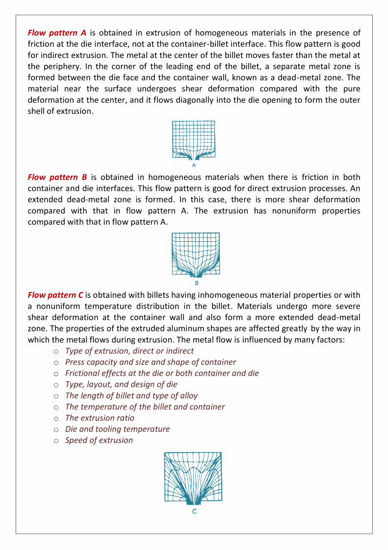
Flow pattern A is obtained in extrusion of homogeneous materials in the presence of friction at the die interface, not at the container-billet interface. This flow pattern is good for indirect extrusion. The metal at the center of the billet moves faster than the metal at the periphery. In the corner of the leading end of the billet, a separate metal zone is formed between the die face and the container wall, known as a dead-metal zone. The material near the surface undergoes shear deformation compared with the pure deformation at the center, and it flows diagonally into the die opening to form the outer shell of extrusion.
Flow pattern B is obtained in homogeneous materials when there is friction in both container and die interfaces. This flow pattern is good for direct extrusion processes. An extended dead-metal zone is formed. In this case, there is more shear deformation compared with that in flow pattern A. The extrusion has nonuniform properties compared with that in flow pattern A.
Flow pattern C is obtained with billets having inhomogeneous material properties or with a nonuniform temperature distribution in the billet. Materials undergo more severe shear deformation at the container wall and also form a more extended dead-metal zone. The properties of the extruded aluminum shapes are affected greatly by the way in which the metal flows during extrusion. The metal flow is influenced by many factors:
o Type of extrusion, direct or indirect o Press capacity and size and shape of container o Frictional effects at the die or both container and die o Type, layout, and design of die o The length of billet and type of alloy o The temperature of the billet and container o The extrusion ratio o Die and tooling temperature o Speed of extrusion
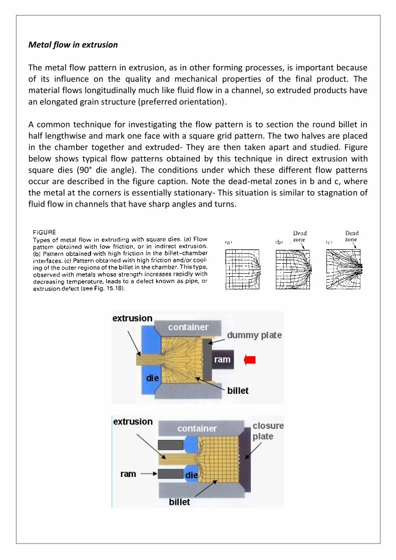
Metal flow in extrusion The metal flow pattern in extrusion, as in other forming processes, is important because of its influence on the quality and mechanical properties of the final product. The material flows longitudinally much like fluid flow in a channel, so extruded products have an elongated grain structure (preferred orientation). A common technique for investigating the flow pattern is to section the round billet in half lengthwise and mark one face with a square grid pattern. The two halves are placed in the chamber together and extruded- They are then taken apart and studied. Figure below shows typical flow patterns obtained by this technique in direct extrusion with square dies (90° die angle). The conditions under which these different flow patterns occur are described in the figure caption. Note the dead-metal zones in b and c, where the metal at the corners is essentially stationary- This situation is similar to stagnation of fluid flow in channels that have sharp angles and turns.