Embed Size (px)
Citation preview

4th Intl WORKSHOP ON WORST-CASE EXECUTION TIME (WCET) ANALYSIS
Catania, Sicily, Italy, June 29, 2004http://www.irisa.fr/wcet2004
in conjunction with the16th Euromicro Intl Conference on Real-Time Systems
Catania, Sicily, Italy, June 30 - July 2, 2004
Session 1: Compiler and run-time optimizations for WCET determination (session chair: Raimund Kirner, TU Vienna, Austria)
Session 2: Low-level analysis (session chair: Stefan Petters, Univ. of York, UK)
Session 3: WCET calculation methods (session chair: Jan Gustafsson, Univ. of Mälardalen, Sweden)
page 3 Predictable Timing Behavior by using Compiler Controlled OperationsV. Hirvisalo, S. Kiminki, University of Helsinki, Finland
page 7 Simplifying WCET Analysis by Code TransformationsH. S. Negi, A. Roychoudhuri, T. Mitra, National University of Singapore
page 11 Optimizing JVM Object Management Operations to Improve WCET PredictabilityA. Corsaro, C. Santoro, University of Washington, USA and University of Catania, Italy
page 15 Influence on Onchip Scratchpad Memories on WCETL. Wehmeyer, P. Marwedel, University of Dortmund, Germany
page 19 Controlling the influence of PCI DMA transfers on WCET of real-time softwareJ. Stohr, A. von Bullow, G. Farber, Technische Universitaet Muenchen, Germany
page 23 Synergetic effects in cache related preemption delaysJ. Staschulat, R. Ernst, Technische Universitaet Braunschweig, Germany
page 27 Component-wise Instruction Cache Behavior PredictionA. Rakib, O. Parshin, S. Thesing, R. Wilhelm, Max Plank instut fur informatik and University of Saarlandes, Germany
page 31 A Distributed WCET Computation Scheme for Smart Card Operating SystemsN. Aissa, C. Rippert, D. Deville, G. Grimaud, University of Lille, France
page 35 Inspection of industrial code for syntactical loop analysisC. Sandberg, Mälardalen University, Sweden
page 39 A New Timing Schema for WCET AnalysisS. Petters, A. Betts, G. Bernat, University of York, UK
page 43 Petri Net Level WCET AnalysisF. Stappert, University of Paderborn, Germany
page 47 Measurement-Based Worst-Case Execution Time Analysis using Automatic Test-Data GenerationR. Kirner, P. Puschner, I. Wenzel, TU Vienna, Austria

Predictable Timing Behavior by using
Compiler Controlled Operation
Vesa Hirvisalo and Sami Kiminki
Helsinki University of Technology1
Laboratory of Information Processing Science
P.O. Box 5400, FIN-02015 HUT, Finland
e-mail: {Vesa.Hirvisalo,Sami.Kiminki}@cs.hut.fi
Abstract
We propose coordinated use of compiler techniques to improvepredictabil-ity of timing behavior of hard real-time systems, and thus, to tighten theirworst-case execution times. We aim at a generic methodology of compileroptimizations that replace the use of unpredictable hardware and operatingsystem features by the use of more predictable features. We call the approachcompiler controlled operation, because it is basedon using compilers to controloperations that are traditionally controlled by hardware or operating systems.As an example of the approach, we overview our work in progress on a smallexperimental system.
1 Introduction
This paper discusses how compiler techniques can be used to build software systemshaving predictable timing behavior. Predictability of timing behavior is needed to
guarantee temporal correctness of hard real-time systems.There are several trends that make giving such guarantees increasingly difficult.
New applications based on the use of real-time software components are rapidlyemerging. To cope with the complexity of the software systems, high-level software
development tools are being adapted. Many applications require high performancein addition to predictable timing behavior. Because of the increasing performancerequirements and the use of generic purpose hardware components to limit pro-duction costs, hardware for real-time systems is becoming complex. These factors
increase dynamisms of the systems and make their timing behavior hard to predict.Timing guarantees are given by schedulability analysis that is typically divided
into intra-task analysis and inter-task analysis. Intra-task analysis finds out worst-case execution times (WCET) for tasks. Improving execution speed can be useless,
even if the improvements yield tight worst-case execution times, unless such tightworst-case execution times can be guaranteed. Inter-task analysis finds out whetherthe tasks can be guaranteed to be scheduled so that they meet their deadlines. Sim-
ilarly, techniques for faster average-case execution can be useless, or even harmful,when inter-task real-time analysis is considered.
1This work has been supported by Finnish Academy grant 51509.
Proc. of the 4th Workshop on WCET analysis 3/50

We concentrate on unpredictability caused by modern hardware and typical op-
erating system features. Such features include – but are not limited to – cache mem-ories, interrupts, and context switches. There are two things common to featuresconsidered by us. First, they make timing analysis difficult by using features that
are not apparent from the application code. Second, more predictable techniquesexist for implementing them in special cases. Using such alternative techniques yieldtighter worst-case execution times.
Our generic solution is to use compiler techniques to transform the software
to use more predictable implementation techniques, when such transformations arepossible. We call the approach compiler control led operation, because it is based onusing compilers to control operations that are traditionally controlled by hardwareor operating systems. Compiler controlled operation is based on static program
analysis. Therefore, it is closely related to the use of WCET analysis methods basedon static program analysis.
The structure of the rest of this paper is the following. In Section 2, we discusscompiler controlled operation in general. In Section 3, we overview our work in
progress on an experimental system that concentrates on using scratchpad memory2
to implement the operation of classic cache hardware and compiler-time schedulingto partially implement a process abstraction. The last section draws some conclu-sions and discusses some related work.
2 Compiler controlled operation
Compiler controlled operation means that some operations in the execution environ-
ment3 of an application are controlled by the compiler that compiles the application.This requires cooperation between the compiler and the execution environment.
The main task of operating systems is to implement process abstraction. Thisincludes managing processes, scheduling processes, and providing processes with
inter-process communication, synchronization and protection. Especially schedulingcombined with synchronization causes problems in timing prediction, because of therun-time decisions made by the operating system.
Modern hardware includes speculative features to increase speed and supporting
features to increase flexibility. The use of such features often make timing predictionhard. The typical speculative hardware feature that causes problems in timingprediction is the cache memory. The combined use of parallel processes and cache
memories can cause severe problems in predictability [7].Traditionally, the programmers of a system are responsible for using predictable
techniques instead of the generic ones (e.g., application-controlled memory manage-ment). There are situations, where this can be automated. The use of predictable
techniques instead of the generic ones can be realized as optimizations done by acompiler. Such compiler optimizations consider the whole execution environment
2Fast on-chip RAM hardware.3The system supporting an application, e.g., the operating system and the whole underlying
hardware.
Proc. of the 4th Workshop on WCET analysis 4/50
instead of the instruction set architecture of the processor. As in traditional com-
pilers, several optimizations can be used in a coordinated way, and they can be usedto promote predictability (e.g., tight WCETs) instead of average speed.
In addition to the transformations, analysis of the need for the transformations
can be done by compilers. As for many WCET tools, user support may be neededto guide the compiler. However, some tasks can be fully automatized, e.g., the useof a scratchpad memory as a cache.
Considered from the point of view of the application developer, transparency is
important regardless whether the analysis can be made fully automatic. Independentof the implementation, the same way of coding and the same interfaces should beused.
3 Work in progress
The pad system consist of two components: a compiler, padCC, and an operatingsystem, padOS. It is a small experimental system that is designed for the study ofplatforms for closed embedded control systems that have periodic hard real-time
timing requirements. The goal of the system is to promote predictable timing andlow energy consumption in high performance applications.
padOS is a small real-time operating system. It supports multitasking, but has
no memory protection, because it is designed for closed applications. It implementsEDF scheduling and prioritized interrupt handling. padOS supports backgroundtasks and inter-process communication.
padCC is a C compiler4. In addition to optimization based on the instruction
set architecture of the target processor, padCC supports optimizations based on theexecution environment. padCC uses scratchpad memory hardware to implementthe operation of classic cache hardware. Instead of using associative memory that isable to handle misses, padCC generates code that copies blocks of main memory to
scratchpad memory (see [6] as an introduction to such scratchpad usage). Thus, allmemory transfers are statically known. The analysis and code generation resembletraditional register allocation and spilling.
padCC does partial compiler-time scheduling. A C program with operating sys-
tem primitives is considered as a concurrent program that is compiled into a sequen-tial program when possible (see [1] for an introduction to static scheduling). Thestatic scheduling is coordinated with the scratchpad memory allocation. Inter-task
scratchpad allocation is realized by giving the sequentialized code to the scratchpadmemory allocator.
The pad system has its roots in on our previous work on cache performanceanalysis [4]. The current version is designed for the AT91EB55 evaluation board,
which has a pipelined ARM7TDMI processor core and 8kB of scratchpad memory.
4padCC does not implement full ANSI C; some complicated language constructs are omitted,e.g., complex type specification features.
Proc. of the 4th Workshop on WCET analysis 5/50
4 Conclusion
The techniques used by us are not unique. The use of simple hardware features
to promote predictability is very common in hard real-time systems. Also, usingcompiler techniques to implement statically-decided operation has been studied.However, we feel that multiple compiler techniques should be used in a coordinatedway to promote predictability. In this way, our approach can be seen as an extension
to the compiler-based software synthesis approach (exemplified by static scheduling)with new hardware-related optimizations (exemplified by scratchpad usage).
Our approach is a compromise between approaches toward very predictable sys-tems (see [2, 8]) and the current practice. The building of predictable systems is
also related to the corresponding analyses (e.g., [9]). Our research is especially de-pendent on the development of WCET analysis based on static program analysisand its relation to hardware development (see [3]). Our current practical work islimited. In the future, we aim at an implementation that makes full scale experi-
mentation possible. Because of the successful previous studies on specific techniques(e.g., [5, 6]), we expect good results.
References
[1] S.A. Edwards. Compiling Concurrent Languages for Sequential Processors. ACM Transactionson Design Automation of Electronic Systems, 8(2):141–187, 2003.
[2] J. Gustafsson, B. Lisper, R. Kirner, and P. Puschner. Input-Dependency Analysis for HardReal-Time Software. In Proceedings of the IEEE International Workshop on Object-OrientedReal-Time Dependable Systems (WORDS), October 2003.
[3] R. Heckmann, M. Langenbach, S. Thesing, and R. Wilhelm. The Influence of Processor Ar-chitecture on the Design and Results of WCET Tools. Proceedings of the IEEE Symposium onReal-Time System (RTSS), 91(7):1038–1054, July 2003. Special Issue on Real-Time Systems.
[4] V. Hirvisalo. Using Static Program Analysis to Compile Fast Cache Simulators. PhD Disser-tation, Helsinki University of Technology, March 2004.
[5] B. Lin. Efficient Compilation of Process-Based Concurrent Programs without Run-TimeScheduling. In Proceedings of the Conference on Design, Automation and Test in Europe(DATE), pages 211–217, February 1998.
[6] P. Marwedel, L. Wehmeyer, M. Verma, S. Steinke, and U. Helmig. Fast, Predictable and LowEnergy Memory References through Architecture-Aware Compilation. In In Proceedings ofDesign Automation Conference Asia and South Pacific (ASPDAC), Yokohama, Japan, January2004.
[7] I. Puaut. Cache Analysis vs Static Cache Locking for Schedulability Analysis in MultitaskingReal-Time Systems. In Proceedings of the International Workshop on Worst-Case ExecutionTime Analysis (WCET), Vienna, Austria, June 2002.
[8] P. Puschner and A. Burns. Writing Temporally Predictable Code. In Proceedings of the IEEEInternational Workshop on Object-Oriented Real-Time Dependable Systems (WORDS), pages85–91, January 2002.
[9] J. Schneider. Cache and Pipeline Sensitive Fixed Priority Scheduling for Preemptive Real-TimeSystems. In Proceedings of the IEEE Real-Time Systems Symposium (RTSS), pages 195–204,Orlando, Florida, USA, November 2000.
Proc. of the 4th Workshop on WCET analysis 6/50

Simplifying WCET Analysis By Code Transformations
Hemendra Singh Negi Abhik Roychoudhury Tulika MitraSchool of Computing, National University of Singapore
{hemendra,abhik,tulika}@comp.nus.edu.sg
ABSTRACTDetermining worst case execution time of a program bystatic analysis is important for the design of real-time soft-ware. WCET analysis at the programming language levelrequires the detection of the longest path in the program. Atighter bound on the WCET of a program can be achievedby identifying the infeasible paths in the program’s controlflow, which is a difficult problem. Due to the branches ina program structure, the number of possible paths in theprogram can grow exponentially. In this paper we present amethod to transform the code such that the number of pathsin the program could be reduced and hence the search spacefor the infeasible paths is brought down. This could reducethe complexity of determining infeasible paths in a programand also result in tighter WCET.
1. INTRODUCTIONThe design of real-time embedded software requires that a
guarantee must be given about the time taken by a program.Especially, in hard real-time systems, where the failure of aprogram to give results within a required amount of timemay have serious consequences, the problem of determiningWorst Case Execution Time (WCET) of a program becomesmore critical. The WCET of a task is also important forscheduling the tasks in real-time systems. However, it is verydifficult to obtain an accurate WCET of a task. Therefore,a tight bound on the WCET by static analysis methods isalways desired to achieve better scheduling of tasks.
The problem of determining the WCET of a program bystatic analysis methods has to be solved at the following twolevels [12]: (1) Programming language level, to discover thelongest path from the start to the end of the program [7] and(2) Micro-architectural level, to take into account the effectof features such as pipeline, cache and branch prediction [6,5]. The determination of WCET at the programming lan-guage level involves the detection of infeasible paths in theprogram and then use that information to give a tight boundon the execution time of the task ([3, 11]). In this paper,we only consider the programming language level analysisof the WCET. We will first describe the types of infeasiblepaths along with some techniques on how to detect them.We then present our idea to reduce their numbers and get abetter estimation of the WCET of a task.
The knowledge about infeasible paths in a program can beused to give a tighter bound on the WCET. There could beinfeasible paths because of the correlation between branches.For example, in Figure 1(A), <3,4,5,6> is an infeasible pathbecause if the outcome of branch at line number 3 is true
1 for(i:= 0; i<limit; i++) 1 sumeven := 0;2 { 2 for (j:=0; j<=limit; j++)3 if ( i < 3 ) 3 {4 S1; 4 if (j % 2 == 0) then5 if ( i > 3 ) 5 sumeven = sumeven + j;6 S2; 6 }7 }
(A) (B)
Figure 1: Infeasible paths due to branch correlation
then the outcome of branch at line number 5 can not betrue. Detection of such types of infeasible paths has beenstudied in [2, 3]. Another type of infeasible paths which canbe present in a program are ones that span over multipleiterations of a loop. For example consider the code to cal-culate the sum of even numbers, as shown in Figure 1(B).If the path <3,4,5,6> is taken in some iteration of the loopthen it is not possible to take it again in the next iterationof the loop.
Detection of infeasible paths in a program is an impor-tant but difficult problem. A technique to detect and useinfeasible path information is presented in [3]. We brieflydescribe their technique here to motivate how it could bebenefited by our code transformation approach. In [3], theauthors have used an effect based technique to determine theinfeasible paths in a program and used this information forcalculating the WCET of a loop. They first determine howa conditional branch can be effected by an assignment to avariable and/or the outcome of another conditional branch.The conditional branch could have one of the three types ofeffects: unknown, fall-through or jump. The effects on theconditional branches by the assignment of a variable are thenexploited while traversing the basic blocks in every path ofthe program to determine whether the path is feasible ornot.
Timing prediction of loops via control flow (as in [3]) posesa lot of problems for timing analyzer. A lot of space isrequired to represent all the paths, unavailability of whichmight abort the timing analyzer. Moreover, a large numberof paths will result in a significant increase of the executiontime of the timing analyzer. Therefore, a method which canreduce the number of paths, will be very useful. We presentour approach as a pre-processing step to reduce the numberof paths and hence reduce the complexity and time takenby the timing analyzer.
2. OUR PROPOSED TECHNIQUE
Proc. of the 4th Workshop on WCET analysis 7/50
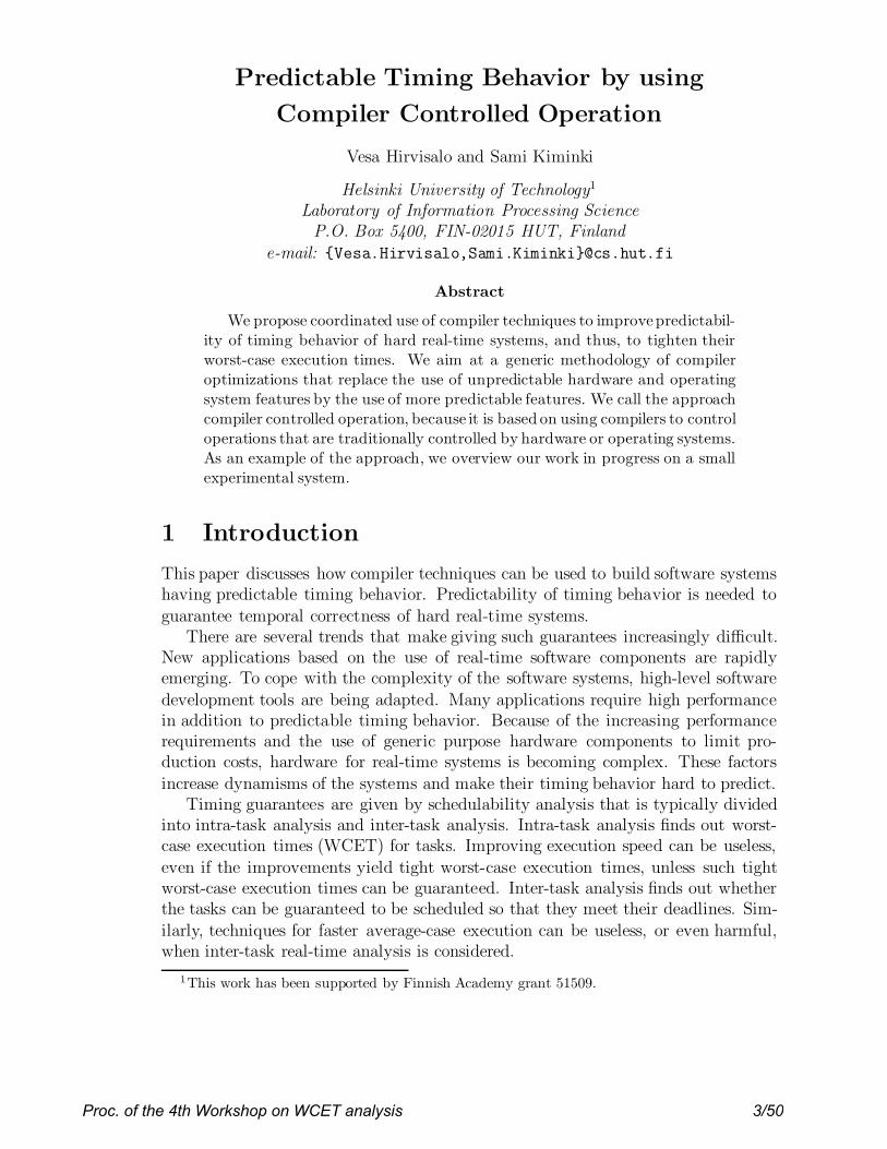
1 x = 0; t = 1;2 for (i = 0; i < 10; i++)3 {4 if ( x == 0)5 S1;6 else7 S2;8 if ( x == 2)9 t = -1;10 if ( x == -1)11 t = 1;12 x = x + t;13 }
Original Code
(A)
1 x = 0; t = 1;2 for (i = 0; i < 10; i++)3 {4 if (x == 0)5 S1;6 else7 {8 S2;9 if (x == 2)10 t = -1;11 else12 if( x == -1)13 t = 1;14 }15 x = x + t;16 }
Code after loop path reduction(B)
Figure 2: Example code to illustrate our technique
We observe that the detection of infeasible paths is in-herently exponential in terms of the number of branch con-straints. Hence, we try to develop a strategy to identifywhich branch conditions can be removed from considerationduring the detection of infeasible paths such that the com-plexity of the detection algorithm could be reduced and atthe same time a tighter bound on the WCET could be pro-vided. We also try to optimize the code such that the num-ber of paths in the code can be reduced. We try to exploitthe constraints generated at branch conditions to optimizethe code. In this section we will illustrate our techniquewith the help of an example and also show how the WCETanalysis as per [3] can be benefited by it.
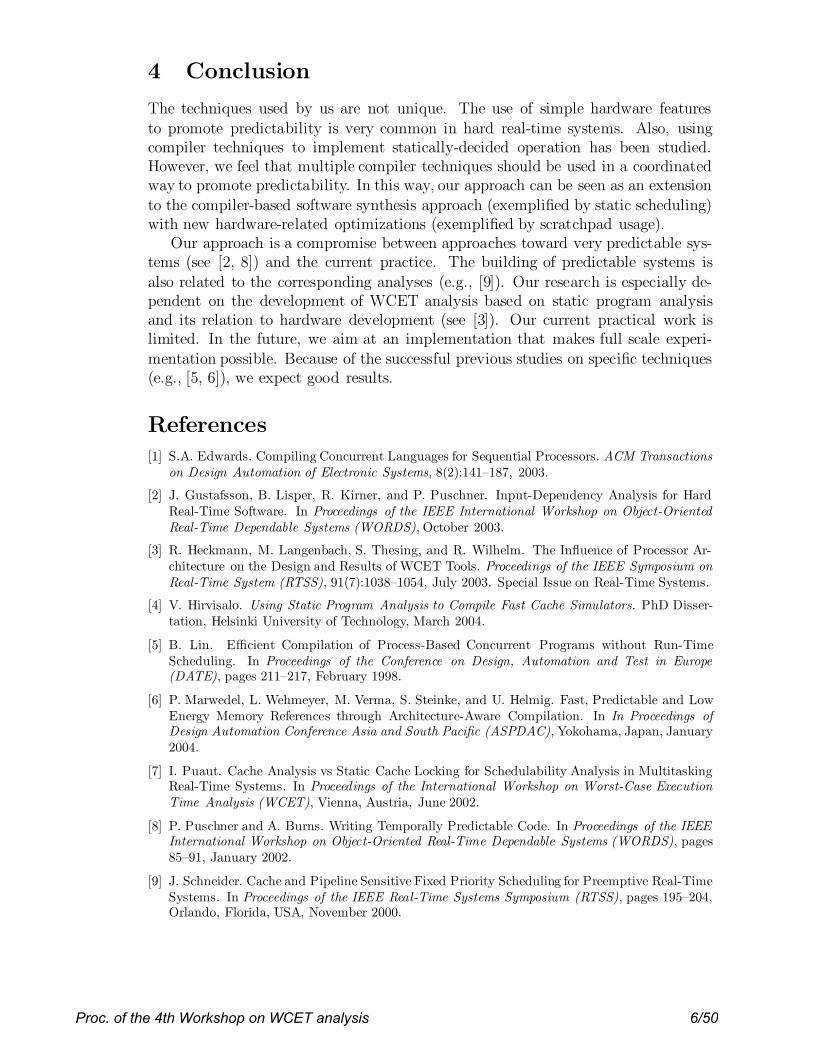
Reducing number of loop paths.Consider the piece ofcode shown in Figure 2(A). The values of x in the Figure2(A) seen at line number 4 are in the form of a simple har-monic motion around the value 0. The sequence of valuesseen for x at line number 4 are (0,1,2,1,0,-1)*. ‘*’ representszero or more repetitions. The control flow graph for thecode in Figure 2(A) is shown in Figure 3(A). From Figure3(A), it is apparent that there are 3 branch conditions and8 paths in each iteration of the loop. The various possiblepaths for each iteration in terms of basic blocks executedare given below.
a : 2 3 4 6 7 8 9 10 11 b : 2 3 4 6 7 8 10 11c : 2 3 4 6 8 9 10 11 d : 2 3 4 6 8 10 11e : 2 3 5 6 7 8 9 10 11 f : 2 3 5 6 7 8 10 11g : 2 3 5 6 8 9 10 11 h : 2 3 5 6 8 10 11
However, it could be observed from the branch constraintsthat the results of branch conditions at block 3 and 6 couldnever be true simultaneously. Therefore block 4 can never beexecuted together with block 7. Moreover, both (true/false)paths from block 3 reaches block 6 and 8 where block 6 is aconditional statement and blocks between 6 and 8 could onlybe executed along with the false path from block 3. Also theconstraint variable (x) of block 6 does not get assigned alongthe true path from block 3. Therefore, blocks 6 and 7 couldbe moved in the false path from block 3. Figure 3(B) showsthe result of such a transformation.
Due to the transformation, the number of paths in theloop gets reduced to 6 from the initial number 8. Usingthe similar observation for conditional branches at blocks 3and 8, the code can be optimized as shown in Figure 3(C),
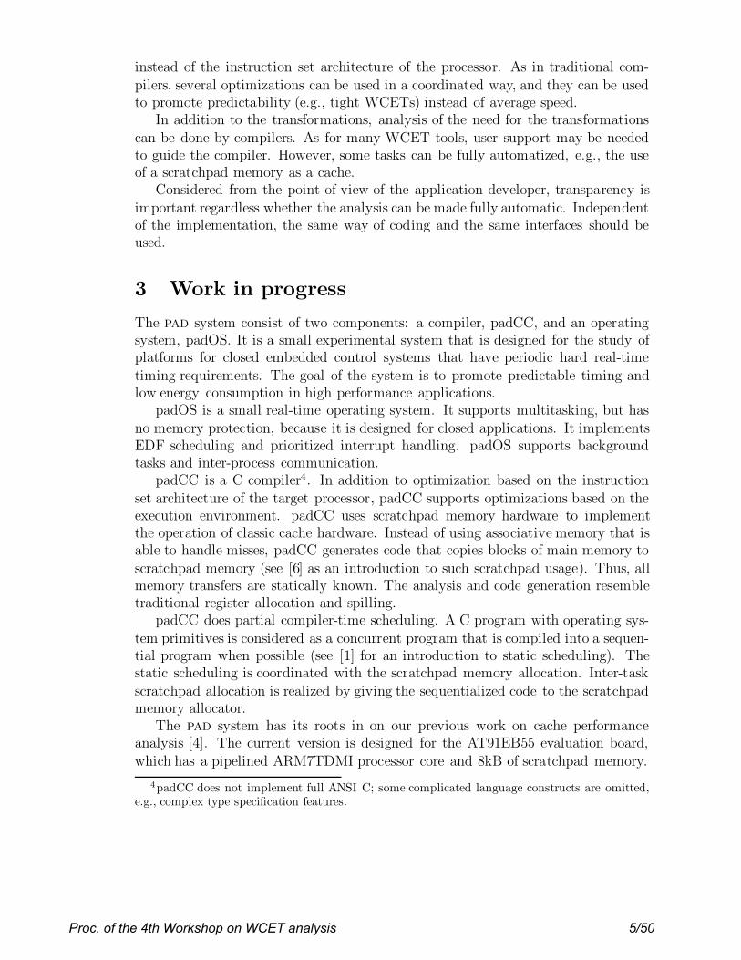
1 x := 0; t := 1;2 for (i := 0; i < 9; i++)3 {4 if ( x == 0)5 S1;6 else7 {8 S2;9 update (x , t);10 }11 x = x + t;12 }
update (x , t){
switch (x){
case 2 : t = -1; break;case -1: t = 1; break;default: t = t;
}}
Figure 4: Example code after path length equaliza-tion
reducing the number of paths to 5. And finally the codecan be modified to as shown in Figure 3(D), reducing thenumber of paths to 4.
The WCET analysis on the basis of the technique givenin [3] will involve the following steps: determining the effectof assignments on the three branch conditions and then us-ing this information to determine the infeasible sequence ofpaths. The technique will be greatly benefited by the opti-mization as the number of paths are decreased and so is thecomplexity of the technique which traverse over the paths todetermine feasibility of paths and also the sequence of pathswhich is infeasible in consecutive iterations.
Equalizing path lengths.The optimization given in theprevious section will transform the original example codeinto an optimized code as shown in Figure 2(B). We now tryto deduce a transformation for this code to further simplifythe WCET analysis. For our purpose, we propose a newtype of block in the CFG along with basic blocks. The newblock will be called as functional block which will representa function. The various paths inside such a functional blockwill not be considered in the WCET analysis. We will seelater in this section that a safe WCET bound can still bereached even though the number of paths considered forWCET are reduced without actually removing such paths.
We can identify the following paths, in each iteration ofloop, from Figure 3(D).
a : 2 3 4 10 11 b : 2 3 5 6 8 10 11c : 2 3 5 6 8 9 10 11 d : 2 3 5 6 7 10 11
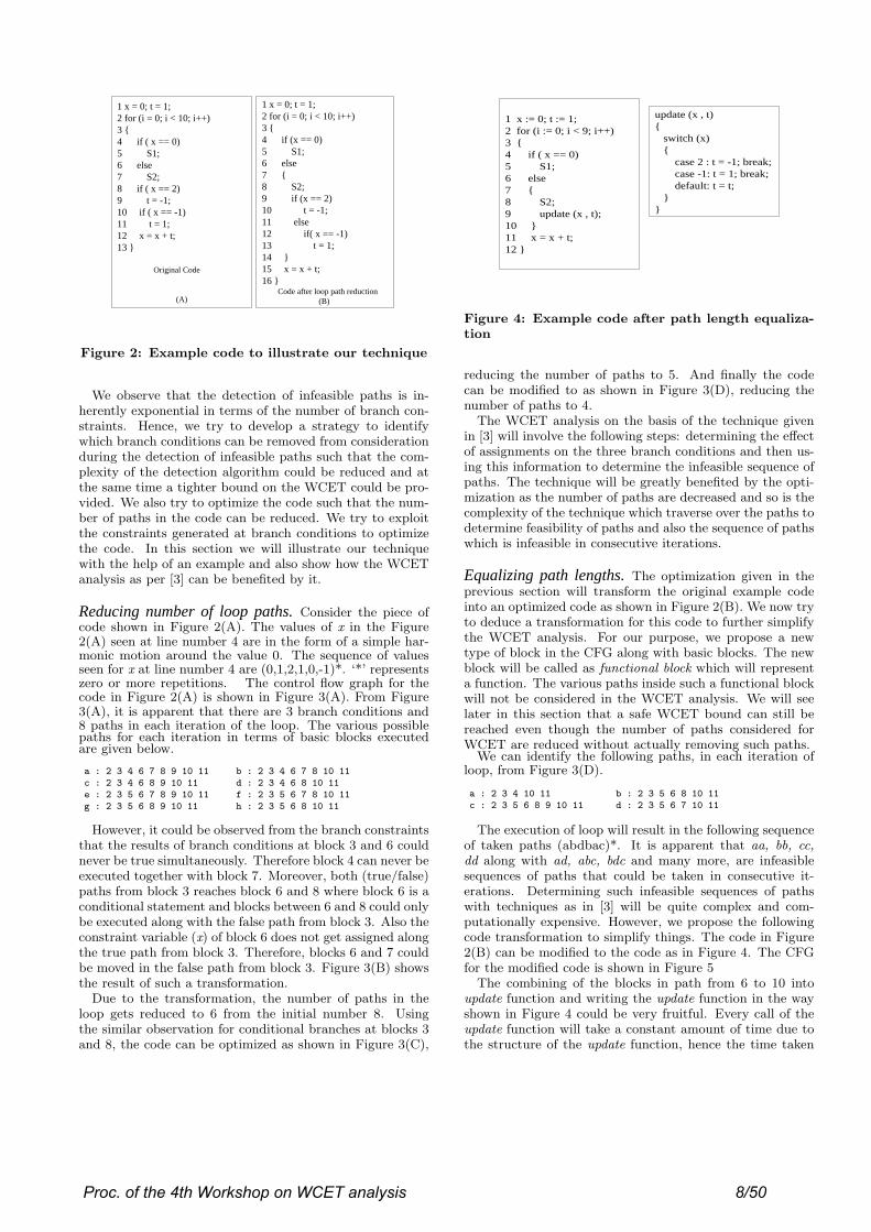
The execution of loop will result in the following sequenceof taken paths (abdbac)*. It is apparent that aa, bb, cc,dd along with ad, abc, bdc and many more, are infeasiblesequences of paths that could be taken in consecutive it-erations. Determining such infeasible sequences of pathswith techniques as in [3] will be quite complex and com-putationally expensive. However, we propose the followingcode transformation to simplify things. The code in Figure2(B) can be modified to the code as in Figure 4. The CFGfor the modified code is shown in Figure 5
The combining of the blocks in path from 6 to 10 intoupdate function and writing the update function in the wayshown in Figure 4 could be very fruitful. Every call of theupdate function will take a constant amount of time due tothe structure of the update function, hence the time taken
Proc. of the 4th Workshop on WCET analysis 8/50
x = 0; t = 1; i = 0
t = 1;
if ( x = = -1)
t = -1;
if ( x = = 2)
S1;
if ( x = = 0 )
if ( i < 10)
x = x + t;
i++;
S2;
Exit loop
T F
TF
F
F
T
T
1
2
3
4 5
6
7
8
9
10
11
12
(A) Original CFG
x = 0; t = 1; i = 0
t = 1;
if ( x = = -1)
t = -1;
if ( x = = 2)
S1;
if ( x = = 0 )
if ( i < 10)
x = x + t;
i++;
S2;
Exit loop
T F
TF
F
F
T
T
1
2
3
4 5
6
7
8
9
10
11
12
(B) After first transformation
x = 0; t = 1; i = 0
t = 1;
if ( x = = -1)
t = -1;
if ( x = = 2)
S1;
if ( x = = 0 )
if ( i < 10)
x = x + t;
i++;
S2;
Exit loop
T F
TF
F
F
T
T
1
2
3
4 5
6
7
8
9
10
11
12
(C) After second transformation
x = 0; t = 1; i = 0
t = 1;
if ( x = = -1) t = -1;
if ( x = = 2)
S1;
if ( x = = 0 )
if ( i < 10)
x = x + t;
i++;
S2;
Exit loop
T F
TF
F
F
T
T
1
2
3
4 5
6
78
9
10
11
12
(D) Final CFG
Figure 3: Reduction of number of loop paths in Control Flow Graph
x = 0; t = 1; i = 0
update (x , t)
S1;
if ( x = = 0 )
if ( i < 10)
x = x + t;
i++;
S2;
Exit loop
T F
F
T
1
2
3
4 5
6
10
11
12
Figure 5: Control Flow Graph after path equaliza-tion
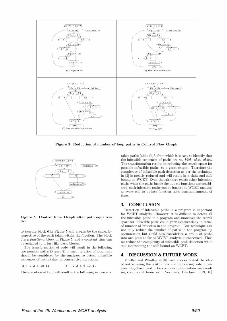
to execute block 6 in Figure 5 will always be the same, ir-respective of the path taken within the function. The block6 is a functional block in Figure 5, and a constant time canbe assigned to it just like basic blocks.
The transformation of code will result in the followingtwo possible paths (Figure 5) in each iteration of loop, thatshould be considered by the analyzer to detect infeasiblesequences of paths taken in consecutive iterations.
a : 2 3 4 10 11 b : 2 3 5 6 10 11
The execution of loop will result in the following sequence of
taken paths (abbbab)*, from which it is easy to identify thatthe infeasible sequences of paths are aa, bbbb, abba, ababa.The transformation results in reducing the search space forpossible infeasible paths, to a great extent. Therefore thecomplexity of infeasible path detection as per the techniquein [3] is greatly reduced and will result in a tight and safebound on WCET. Even though there exists other infeasiblepaths when the paths inside the update functions are consid-ered, such infeasible paths can be ignored in WCET analysisas every call to update function takes constant amount oftime.
3. CONCLUSIONDetection of infeasible paths in a program is important
for WCET analysis. However, it is difficult to detect allthe infeasible paths in a program and moreover the searchspace for infeasible paths could grow exponentially in termsof number of branches in the program. Our technique cannot only reduce the number of paths in the program byoptimization but could also consolidate a group of pathsinto one path as far as WCET analysis is concerned. Thuswe reduce the complexity of infeasible path detection whilestill maintaining the safe bound on WCET.
4. DISCUSSION & FUTURE WORKMueller and Whalley in [8] have also exploited the idea
of restructuring the control flow and replicating code. How-ever, they have used it for compiler optimization via avoid-ing conditional branches. Previously, Puschner in [9, 10]
Proc. of the 4th Workshop on WCET analysis 9/50
(A)
f1(i){ switch (i){
case 1: i= i+1;break;
case 2: i = j+0;break;
case 3: i = i+3;break;
case 4: i = i+1;break;
}}
f2(i){switch (i){
case 5:printf (" i = %d
\n",i);break;
case 6: printf (" j = %d
\n",j);break;
}}
(B)
#include <stdio.h> main() {
int i, j;printf ("enter a number: "); scanf ("%d", &i); if (i == 1)
i = i+1; if (i == 2)
i = j; if (i == 3)
i = i+3; if (i == 4)
++i; if (i == 5)
printf (" i = %d\n",i); if (i == 6)
printf (" j = %d\n",j); }
#include <stdio.h> main() {
int i, j; printf ("enter a number: "); scanf ("%d", &i);f1(i);f2(i);
}
Figure 6: Example Code: Toy6
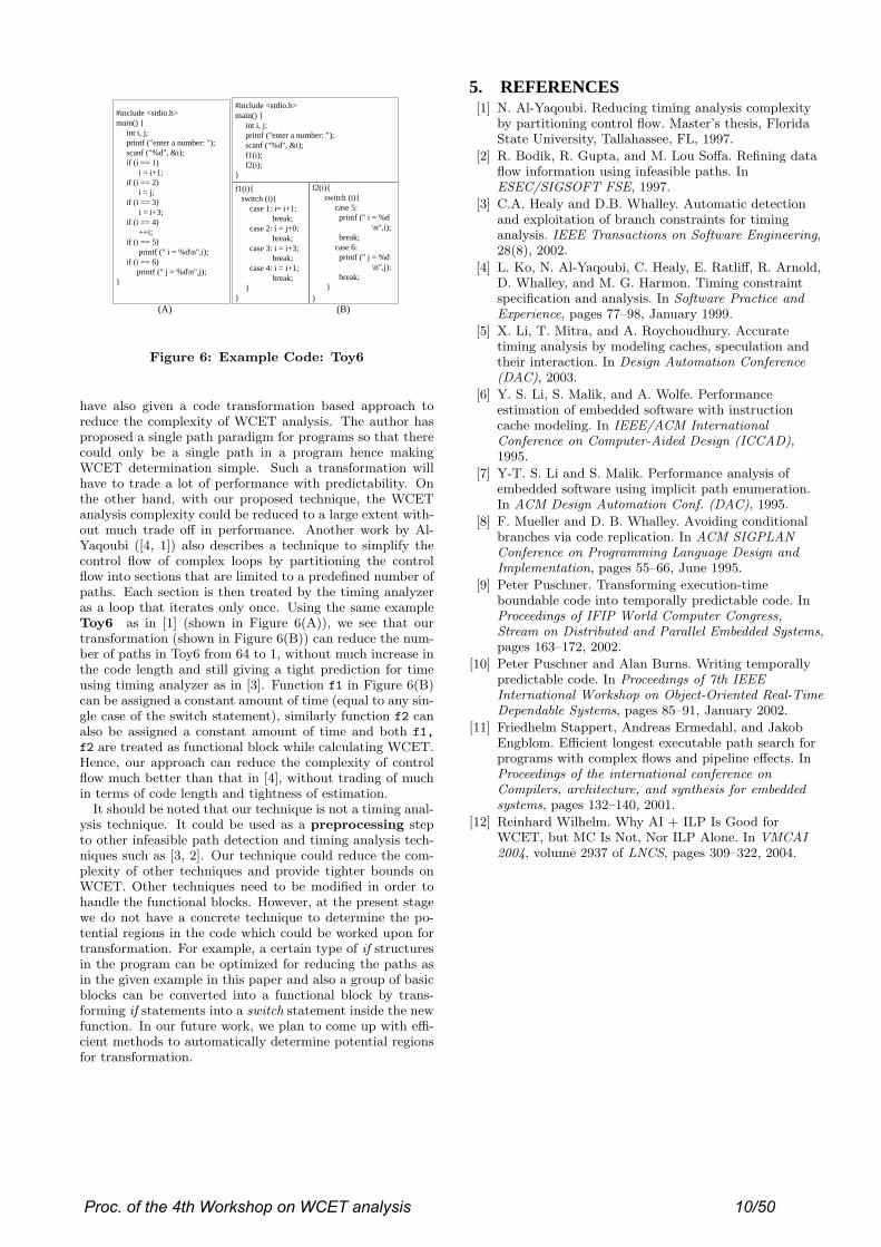
have also given a code transformation based approach toreduce the complexity of WCET analysis. The author hasproposed a single path paradigm for programs so that therecould only be a single path in a program hence makingWCET determination simple. Such a transformation willhave to trade a lot of performance with predictability. Onthe other hand, with our proposed technique, the WCETanalysis complexity could be reduced to a large extent with-out much trade off in performance. Another work by Al-Yaqoubi ([4, 1]) also describes a technique to simplify thecontrol flow of complex loops by partitioning the controlflow into sections that are limited to a predefined number ofpaths. Each section is then treated by the timing analyzeras a loop that iterates only once. Using the same exampleToy6 as in [1] (shown in Figure 6(A)), we see that ourtransformation (shown in Figure 6(B)) can reduce the num-ber of paths in Toy6 from 64 to 1, without much increase inthe code length and still giving a tight prediction for timeusing timing analyzer as in [3]. Function f1 in Figure 6(B)can be assigned a constant amount of time (equal to any sin-gle case of the switch statement), similarly function f2 canalso be assigned a constant amount of time and both f1,
f2 are treated as functional block while calculating WCET.Hence, our approach can reduce the complexity of controlflow much better than that in [4], without trading of muchin terms of code length and tightness of estimation.
It should be noted that our technique is not a timing anal-ysis technique. It could be used as a preprocessing stepto other infeasible path detection and timing analysis tech-niques such as [3, 2]. Our technique could reduce the com-plexity of other techniques and provide tighter bounds onWCET. Other techniques need to be modified in order tohandle the functional blocks. However, at the present stagewe do not have a concrete technique to determine the po-tential regions in the code which could be worked upon fortransformation. For example, a certain type of if structuresin the program can be optimized for reducing the paths asin the given example in this paper and also a group of basicblocks can be converted into a functional block by trans-forming if statements into a switch statement inside the newfunction. In our future work, we plan to come up with effi-cient methods to automatically determine potential regionsfor transformation.
5. REFERENCES[1] N. Al-Yaqoubi. Reducing timing analysis complexity
by partitioning control flow. Master’s thesis, FloridaState University, Tallahassee, FL, 1997.
[2] R. Bodik, R. Gupta, and M. Lou Soffa. Refining dataflow information using infeasible paths. InESEC/SIGSOFT FSE, 1997.
[3] C.A. Healy and D.B. Whalley. Automatic detectionand exploitation of branch constraints for timinganalysis. IEEE Transactions on Software Engineering,28(8), 2002.
[4] L. Ko, N. Al-Yaqoubi, C. Healy, E. Ratliff, R. Arnold,D. Whalley, and M. G. Harmon. Timing constraintspecification and analysis. In Software Practice andExperience, pages 77–98, January 1999.
[5] X. Li, T. Mitra, and A. Roychoudhury. Accuratetiming analysis by modeling caches, speculation andtheir interaction. In Design Automation Conference(DAC), 2003.
[6] Y. S. Li, S. Malik, and A. Wolfe. Performanceestimation of embedded software with instructioncache modeling. In IEEE/ACM InternationalConference on Computer-Aided Design (ICCAD),1995.
[7] Y-T. S. Li and S. Malik. Performance analysis ofembedded software using implicit path enumeration.In ACM Design Automation Conf. (DAC), 1995.
[8] F. Mueller and D. B. Whalley. Avoiding conditionalbranches via code replication. In ACM SIGPLANConference on Programming Language Design andImplementation, pages 55–66, June 1995.
[9] Peter Puschner. Transforming execution-timeboundable code into temporally predictable code. InProceedings of IFIP World Computer Congress,Stream on Distributed and Parallel Embedded Systems,pages 163–172, 2002.
[10] Peter Puschner and Alan Burns. Writing temporallypredictable code. In Proceedings of 7th IEEEInternational Workshop on Object-Oriented Real-TimeDependable Systems, pages 85–91, January 2002.
[11] Friedhelm Stappert, Andreas Ermedahl, and JakobEngblom. Efficient longest executable path search forprograms with complex flows and pipeline effects. InProceedings of the international conference onCompilers, architecture, and synthesis for embeddedsystems, pages 132–140, 2001.
[12] Reinhard Wilhelm. Why AI + ILP Is Good forWCET, but MC Is Not, Nor ILP Alone. In VMCAI2004, volume 2937 of LNCS, pages 309–322, 2004.
Proc. of the 4th Workshop on WCET analysis 10/50

Optimizing JVM Object Management Operations toImprove WCET Predictability
Angelo CorsaroWashington University
Department of Computer Science and Engineering1 Brookings Drive, BOX 1045, St. Louis, 63130
Missouri, USAEMail: [email protected]
Corrado SantoroUniversity of Catania - Engineering Faculty
Department of Computer Science andTelecommunication Engineering
Viale A. Doria, 6 - 95125 - Catania, ItalyEMail: [email protected]
Abstract— This paper describes the optimizations introducedin Juice, a J2ME virtual machine for embedded systems. Theseoptimizations are designed to make possible the determinationof the WCET the JVM bytecodes related to object and arraymanagement. The solution proposed, which is based on managingthe memory heap as a set ofchunks of fixed size, allows to executethose bytecodes either in a constant time or in a linear time withan upper bound that can be determined.
Index Terms— Real-time Java, WCET Analysis, EmbeddedSystems, Juice VM
I. I NTRODUCTION
In real-time systems, determination of the worst-case execu-tion time (WCET) plays a fundamental role in task feasibilityanalysis and scheduling. Frameworks for WCET analysis [2]are based on the determination of the expected executiontime of each instruction of the given task. In a real-timeJava environment, this implies to obtain the WCET of eachJava bytecode present in the task to be scheduled. Suchan analysis could be hard for those bytecodes that need tomanipulate Java heap or access the structure of involvedobjects, class/interface hierarchy, etc. This family of bytecodesrequires an optimized virtual machine, otherwise the executionof the related operations could be affected by a jitter thatmakes WCET analysis impossible.
In such a context, this paper describes the optimizationsintroduced inJuice [4], a J2ME virtual machine [12] designedby the authors to be run upon NUXI [9], a light executivefor Intel-based embedded systems1. Juice uses a heap man-agement technique and an object layout that facilitate objectallocation, object’s attributes access and garbage collection.The employed technique allows to perform these operations ina predictable time, thus deriving in a precise WCET analysisfor real-time Java tasks.
The paper focuses on object allocation/deallocation andattribute reading/writing, showing how these operation canadvantage of the proposed heap management technique. Thepros and cons are presented, together with a comparison withsimilar approaches, aiming at validating the choices made.
1NUXI can be downloaded athttp://nuxi.iit.unict.it
II. H EAP MANAGEMENT
Operations related to heap management are those executedwhen an object has to be allocated or collected. In general, thetime required to perform the creation of a new object dependson the size of the object that, in turn, depends on the amount ofattributes declared in the object’s class and in its ancestors. Theoperations required for object allocation can be summarizedas: (i) determine the number and the type of the attributes, inorder to compute the size of the memory area to get from theheap, and (ii) find a contiguous area of free memory, in theheap, where to allocate the created object.
The former operation could imply to navigate class hier-archy in order to find all the attributes the object possesses;indeed, number of attributes can be computed at class loadingtime, thus storing object size in a field of the structurerepresenting the class in memory. The latter operation insteadimplies to scan the heap until a piece of free memory, whosesize is greater than or equal to the requested amount, is found.This operation requires, in general, a time dependent on thesize of the heap and of the object [8], [5], [14]. This means thatthe WCET of such an operation cannot be exactly computed,but only upper bounded with a limit that depends on heapsize. However, even if finding the right place could imply toperform scanning until the end of the heap, objects are oftensmall, and the right place is (practically and on average) foundin very few steps. As a consequence, the theoretical WCETis, in the majority of cases, quite greater than the real amountof time required: this provokes an evident waste of CPU time.
The solution we propose borrows some simple principlesfrom Unix-style file system handling techniques and providesan efficient algorithm to allocate any object in a time thatdepends only on the size of the allocated object, a parameterthat can be exactly estimated with a static bytecode analysis.Our solution subdivides the entire heap in a sequence ofchunksof a fixed sizeCS. All chunks are organized in a linked list,started by a pointerFC representing thefree list of chunks(the first four bytes of each chunk represent the pointer to thenext free chunk). Allocating a chunk means to pick it fromFC, moving the latter to the next free chunk; while releasinga chunk implies to place it at the head of the free list, thus
Proc. of the 4th Workshop on WCET analysis 11/50
data[0]
data[1]...
data[H−4]
header
...
data[H+B−4]
data[H−3]
...
data[H+(B+1)B−4]
data[H+BB−3]
object pointer...
data[H+2B−4]
data[H+B−3]
...
...... ...
...
... data[H+BBB+BB−3]
data[H+(B+1)B−3]
data[H+(B+2)B−4]
data[H+BBB+BB+B−4]
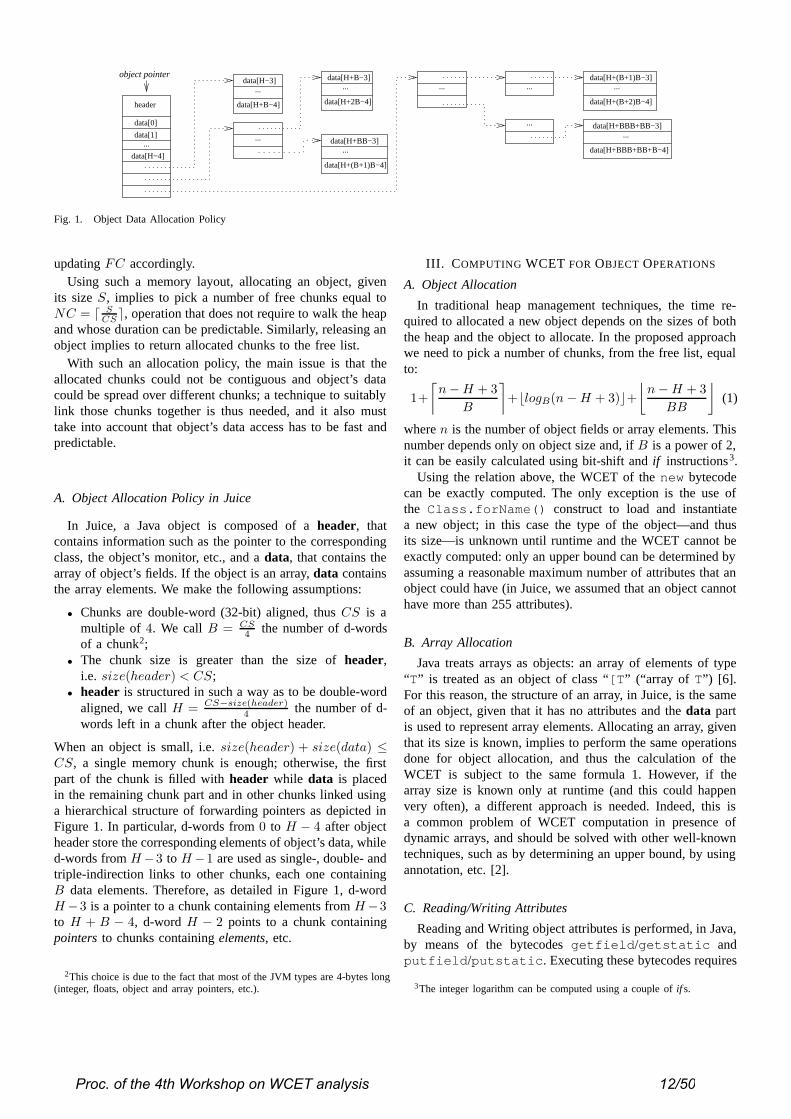
Fig. 1. Object Data Allocation Policy
updating FC accordingly.Using such a memory layout, allocating an object, given
its size S, implies to pick a number of free chunks equal toNC = � S
CS �, operation that does not require to walk the heapand whose duration can be predictable. Similarly, releasing anobject implies to return allocated chunks to the free list.
With such an allocation policy, the main issue is that theallocated chunks could not be contiguous and object’s datacould be spread over different chunks; a technique to suitablylink those chunks together is thus needed, and it also musttake into account that object’s data access has to be fast andpredictable.
A. Object Allocation Policy in Juice
In Juice, a Java object is composed of a header, thatcontains information such as the pointer to the correspondingclass, the object’s monitor, etc., and a data, that contains thearray of object’s fields. If the object is an array, data containsthe array elements. We make the following assumptions:
• Chunks are double-word (32-bit) aligned, thus CS is amultiple of 4. We call B = CS
4 the number of d-wordsof a chunk2;
• The chunk size is greater than the size of header,i.e. size(header) < CS;
• header is structured in such a way as to be double-wordaligned, we call H = CS−size(header)
4 the number of d-words left in a chunk after the object header.
When an object is small, i.e. size(header) + size(data) ≤CS, a single memory chunk is enough; otherwise, the firstpart of the chunk is filled with header while data is placedin the remaining chunk part and in other chunks linked usinga hierarchical structure of forwarding pointers as depicted inFigure 1. In particular, d-words from 0 to H − 4 after objectheader store the corresponding elements of object’s data, whiled-words from H−3 to H−1 are used as single-, double- andtriple-indirection links to other chunks, each one containingB data elements. Therefore, as detailed in Figure 1, d-wordH −3 is a pointer to a chunk containing elements from H−3to H + B − 4, d-word H − 2 points to a chunk containingpointers to chunks containing elements, etc.
2This choice is due to the fact that most of the JVM types are 4-bytes long(integer, floats, object and array pointers, etc.).
III. COMPUTING WCET FOR OBJECT OPERATIONS
A. Object Allocation
In traditional heap management techniques, the time re-quired to allocated a new object depends on the sizes of boththe heap and the object to allocate. In the proposed approachwe need to pick a number of chunks, from the free list, equalto:
1+
⌈n − H + 3
B
⌉+�logB(n − H + 3)�+
⌊n − H + 3
BB
⌋(1)
where n is the number of object fields or array elements. Thisnumber depends only on object size and, if B is a power of 2,it can be easily calculated using bit-shift and if instructions3.
Using the relation above, the WCET of the new bytecodecan be exactly computed. The only exception is the use ofthe Class.forName() construct to load and instantiatea new object; in this case the type of the object—and thusits size—is unknown until runtime and the WCET cannot beexactly computed: only an upper bound can be determined byassuming a reasonable maximum number of attributes that anobject could have (in Juice, we assumed that an object cannothave more than 255 attributes).
B. Array Allocation
Java treats arrays as objects: an array of elements of type“T” is treated as an object of class “[T” (“array of T” ) [6].For this reason, the structure of an array, in Juice, is the sameof an object, given that it has no attributes and the data partis used to represent array elements. Allocating an array, giventhat its size is known, implies to perform the same operationsdone for object allocation, and thus the calculation of theWCET is subject to the same formula 1. However, if thearray size is known only at runtime (and this could happenvery often), a different approach is needed. Indeed, this isa common problem of WCET computation in presence ofdynamic arrays, and should be solved with other well-knowntechniques, such as by determining an upper bound, by usingannotation, etc. [2].
C. Reading/Writing Attributes
Reading and Writing object attributes is performed, in Java,by means of the bytecodes getfield/getstatic andputfield/putstatic. Executing these bytecodes requires
3The integer logarithm can be computed using a couple of if s.
Proc. of the 4th Workshop on WCET analysis 12/50

✞dword getfield_quick (HOBJECT p, int index){
dword * p1, * p2, * p3;if (index < (H - 3)) return p->data[index];else {
index -= (H - 3);if (index < B) {
/ / follow index at H - 3p1 = (dword *)p->data[H - 3];return p1[index];
}else if (index < B*B) {
/ / follow index at H - 2p2 = (dword *)p->data[H - 2];p1 = (dword *)p2[index / B];return p1[index % B];
}else {
/ / follow index at H - 1int i0 = index / (B*B);int i1 = (index % (B*B)) / B;int i2 = index % B;p3 = (dword *)p->data[H - 1];p2 = (dword *)p3[i0];p1 = (dword *)p2[i1];return p1[i2];
}}
}✡✝ ✆
Fig. 2. Juice’s getfield code fragment
access to constant pool and class structure [6], operationthat is, in general, heavy and unpredictable. For this reason,those bytecodes are replaced (at their first execution) with the“quick” variant, which take, as operand, directly the attributeindex (in the object’s attributes array). Using such an approach,the execution of these bytecodes can be fast and predictable.
Juice adopts an ahead-of-time pre-link and resolution pro-cess. Since Juice is a virtual machine for embedded system,Java classes are intended to be “ROM’ ized” . To this aim,the pre-linker provided by Juice, together with transform-ing classes into a ROMable representation, replaces eachget-/putfield attribute with the “quick” version. Attributeindex is thus referred to the array stored in the object. Giventhat attributes can be spread over different chunks, the accesscould require to navigate the chain of pointers. The code ofsuch an operation is reported in Figure 2 for the getfieldbytecode: as it can be seen, it is fast and its WCET can beexactly determined.
D. Juice Heap Layout and Garbage Collection
One of the main known issues that impede the use of Javain (hard) real-time environments is the presence of the garbagecollector. The instants in which the GC is activated and theduration of its execution cannot be predicted, and thus anyWCET/schedulability analysis is, in general, impossible. Suchproblems are overcome by the Real-Time Specification forJava (RTSJ) [3] with the introduction of scoped memory, whileother research proposes alternative approaches for real-timegarbage collection [11], [1].
In our approach, the use of memory chunks greatly sim-plifies garbage collection, independently of the particularalgorithm that is then used (reference-counting, three-color-marking, etc.) [13]. This is mainly due to the fact that chunksare fixed-sized and that free chunks are organized in a linked
list, therefore no compacting process is needed. Collectingthe memory associated to an object no longer used impliesto return the associated chunks to the free list, one-by-one,operation that can be performed also incrementally, n chunksper time.
Using such a characteristic, the garbage collector of Juice 4
is designed to perform a known number of operations eachtime it is invoked. More specifically, the cost to pay when anobject occupying n chunks has to be allocated is to ask thegarbage collection to free, at most, n unreferenced chunks.With such an approach, execution of the GC is always tied toobject allocation (i.e. when new free memory could be needed)and its duration can be predicted.
IV. KNOWN ISSUES
The heap management policy presented in this paper, even ifit guarantees good allocation performances and predictabilityin WCET determination, suffers of two main problems: limitednumber of fields/array elements and memory fragmentation.These issues must be analyzed in order to understand theirimpact on the execution of a Java real-time program.
A. Limited data elements
The former problem is due to the fact that, as shown inFigure 1, the maximum number of elements the data partcan refer is H + BBB + BB + B − 4. In Juice, where wechose B = 32 (and thus H = 24), this limit is equal to33844. It is obviously enough for object’s attribute (as statedin Sect. III-A, in Juice an object cannot have more than 255attributes), but it could be a problem for array allocation, since,even if not so frequent, above all in embedded applications,there may be a case in which larger arrays are needed. Apossible solution could be to increase B, but, as we will seein the following, this choice provokes an increment of memoryinternal fragmentation.
The solution adopted in Juice is to flag large arrays withan unused bit of the header, and to add another level ofindirection in the data array. This implies an upper boundequal to H + BBBB + BBB + BB + B − 5, i.e. 1082419elements when B = 32. This new upper bound can now beconsidered enough, given also that it implies 4 MBytes forarray allocation and about 34 MBytes (at least) to allocateobjects relevant to array elements. However, the introductionof such a variation implies an additional cost to pay whenaccessing array elements; this cost is useless when the limitof 33844 elements is not overcome by the application: for thisreason, in Juice a command-line flag is used to activate the“ large array” option.
B. Memory Fragmentation
The second issue is relevant to memory fragmentation: thegiven approach provokes both external and internal fragmen-tation. The former is due to the fact that an object couldbe spread over non-contiguous chunks: indeed, this approach
4In the current implementation, the GC is based on a simple reference-counting
Proc. of the 4th Workshop on WCET analysis 13/50

100
1000
10000
100000
1e+06
1e+07
16 32 64 128
Attr
ibut
e/A
rray
Bou
nd M
and
Was
ted
Mem
ory
(in b
ytes
)
B
Attribute/Array Bound MWasted Memory (10 objects)Wasted Memory (50 objects)
Wasted Memory (100 objects)Wasted Memory (500 objects)
Fig. 3. Wasted Memory due to Internal Fragmentation
does not fit the working scheme of a CPU cache and thuscan lead to performance reduction. However, we remind that,in general, the use of caching could be a problem for (hard)real-time systems, since caches may introduce large jitters inCPU opcode executions thus affecting WCET calculation [7].
Internal fragmentation, derived from the unused space left inchunks, is instead more important, since it implies a reductionof the amount of available memory. For this reason, the valueof B should be chosen in such a way as to find a goodcompromise between the allowed maximum number of object’sattributes and array elements, which is M = H + BBB +BB + B − 4, and the degree of internal fragmentation.
Figure 3 reports the trend of M and the amount of wastedmemory, due to internal fragmentation, with respect to avalue of B ranging from 16 to 128 d-words. The amountof wasted memory is measured considering 10, 50, 100 and500 allocated objects with no attributes, thus producing themaximum fragmentation. As the Figure reports, the wastedmemory with 500 objects, choosing B = 32 as in Juice, isapproximatively 42 KBytes, a not-so-high cost to be payedfor the use of fixed-sized memory chunks.
V. RELATED WORK
An interesting approach similar to ours is that providedby the JamaicaVM [11]. This virtual machine uses memorychunks too, but each chunk is 32-bytes long (four d-words).Objects’ fi elds and array elements are allocated using a hi-erarchical 4-order tree-based structure, where leaf nodes arethe fields/elements, while non-leaf nodes contains pointers tochildren nodes.
With respect to our approach, that of JamaicaVM impliesa negligible degree of internal fragmentation, and thereforedoes not suffer of a significant memory wasting problem.However, since the chunk is small, external fragmentation isquite high (even if, when possible [10] chunks are allocatedcontiguously). In addition, with respect to our approach, morememory is needed, for the same number of attributes/elements,due to the presence of non-leaf nodes with pointers.
As for array limits, JamaicaVM does not present upperbounds in array size as in Juice thanks to the tree structure, but
it requires to always traverse the entire tree hierarchy until theelement is found: this operation, even if predictable for WCETanalysis, could have evident consequences on performances.
However, all of the considerations above are made on thebasis of qualitative evaluations of the compared approaches. Amore in-depth analysis, together with quantitative performancemeasurements, are indeed necessary for a complete evaluationof the pros and cons of the presented approach. We plan toperform these measurements in the immediate future.
VI. CONCLUSIONS
This paper described the heap management and objectallocation techniques employed in the Juice virtual machine.As it has been shown, the proposed approach was studied inorder to have operations for object allocation and access notonly optimized but, above all, with a predictable executiontime, making possible the determination of WCET. Even if theprovided analysis showed that the proposed technique presentssome limits, these are not so critical for the embedded systemsenvironment for which Juice was designed.
REFERENCES
[1] David Bacon and Perry Cheng. The Metronome: An Integrated Ap-proach to Garbage Collection in Real-Time Systems. In Proceedingsof 1st Workshop on Java Technologies for Real-time and EmbeddedSystems (JTRES 2003), OTM’03 Federated Conferences. LNCS 2889,Springer, Nov. 2003.
[2] Iain Bate, Guillem Bernat, and Peter Puschner. Java Virtual-MachineSupport for Portable Worst-Case Execution-Time Analysis. In Proc.5th IEEE International Symposium on Object-Oriented Real-Time Dis-tributed Computing, pages 83–90, Apr. 2002.
[3] Bollella, Gosling, Brosgol, Dibble, Furr, Hardin, and Turnbull. TheReal-Time Specification for Java. Addison-Wesley, 2000.
[4] Angelo Corsaro and Corrado Santoro. A C++ Native Interface forInterpreted JVMs. In et al. Robert Meersman, Zahir Tari, editor, 1st Intl.Workshop on Java Technologies for Real-time and Embedded Systems(JTRES’03). Lecture Notes in Computer Science 2889, Springer Verlag,2003.
[5] Steven M. Donahue, Matthew P. Hampton, Morgan Deters, Jonathan M.Nye, Ron K. Cytron, and Krishna M. Kavi. Storage allocation for real-time, embedded systems. In Thomas A. Henzinger and Christoph M.Kirsch, editors, Embedded Software: Proceedings of the First Interna-tional Workshop, pages 131–147. Springer Verlag, 2001.
[6] Tim Lindholm and Frank Yellin. The Java(TM) Virtual MachineSpecification. Addison-Wesley, 2nd edition, 1999.
[7] Isabelle Puaut. Cache analysis vs static cache locking for schedulabilityanalysis in multitasking real-time systems. In Proc. of the 2nd Interna-tional Workshop on worst-case execution time analysis, in conjunctionwith the 14th Euromicro Conference on Real-Time Systems, Jun. 2002.
[8] Isabelle Puaut. Real-Time Performances of Dynamic Memory AllocationAlgorithms. In 14th Euromicro Conference on Real-Time Systems, Jun.2002.
[9] Corrado Santoro. An Operating System in a Nutshell. Internal Report,Dept. of Computer Engineering and Telecommunication, UniCT, Italy,2002.
[10] Fridtjof Siebert. Eliminating External Fragmentation in a Non-MovingGarbage Collector for Java. In Compilers, Architectures and Synthesisof Embedded Systems (CASES’00), Nov. 2000.
[11] Fridtjof Siebert. Hard Realtime Garbage Collection in Modern ObjectOriented Programming Languages. AICAS GmbH, 2003.
[12] Sun Microsystems inc. Java 2 Micro Edition Home Page. http://java.sun.com/j2me, 2002.
[13] Paul R. Wilson. Uniprocessor Garbage Collection Techniques. In Proc.Int. Workshop on Memory Management, Saint-Malo (France), 1992.Springer-Verlag.
[14] Paul R. Wilson, Mark S. Johnstone, Michael Neely, and David Boles.Dynamic storage allocation: A survey and critical review. In Proc. Int.Workshop on Memory Management, Kinross Scotland (UK), 1995.
Proc. of the 4th Workshop on WCET analysis 14/50
Influence of Onchip Scratchpad Memorieson WCET prediction∗
Lars Wehmeyer, Peter MarwedelEmbedded Systems Group, CS Dept., University of Dortmund, Germany
{Lars.Wehmeyer, Peter.Marwedel}@udo.edu
May 27, 2004
Abstract
In contrast to standard PCs and many high-performance com-puter systems, systems that have to meet real-time requirementsusually do not feature caches, since caches primarily improvethe average case performance, whereas their impact on WCETis generally hard to predict. Especially in embedded systems,scratchpad memories have become popular. Since these small,fast memories can be controlled by the programmer or the com-piler, their behavior is perfectly predictable. In this paper, westudy for the first time the impact of scratchpad memories onworst case execution time (WCET) prediction. Our results in-dicate that scratchpads can significantly improve WCET at noextra analysis cost.
1 Introduction
For the currently available technologies, there is an increas-ing speed gap between processor speeds and memory speeds.Caches are being used in order to bridge that gap, especially inPC-like systems. However, the approach used in such systemshas some disadvantages for embedded systems:
1. Caches are known to be one of the main contributors tothe total energy consumption of systems [1], and
2. Caches are typically designed to improve the average caseaccess time.
Analysis techniques to determine their contribution to theworst case execution time are complicated and, for some re-placement policies, just missing. Scratch pad memories (some-times also known as tightly coupled memories) are small mem-ories mapped into the address space of a system. They are usedwhenever an address is within the address range assigned tothat memory. Scratch pad memories are more energy efficientthan main memories (since they are smaller) but also more ef-ficient than caches (since only the required information is readfrom or written into the scratchpad memory). Scratchpads arecurrently being used by designers in a very ad-hoc fashion, and
∗This work has been sponsored in part by EU-project ARTIST2
a comprehensive methodology of how to use them is, surpris-ingly, still missing.
Earlier work proposed compile-time algorithms for mappinghot spots of applications to scratchpad memories. This workwas mainly motivated by the resulting energy savings, muchof which result from a reduction of the average access time.However, the algorithms also have an extremely beneficial im-pact on worst case execution time estimation: it is fully pre-dictable which memory will be used for a certain memory ac-cess. Hence, scratchpad memories provide 100% predictabilityconcerning the timing of memory references. This predictabil-ity is explored in the current paper. In this work, we combineviews from three different perspectives: an architectural viewon scratchpad-based memory structures, a compiler view onhow to map hot spots to these memories and a real-time systemview on the resulting WCET. To the best of our knowledge, it isthe first paper that provides a detailed analysis of the impact onthe WCET of optimized mappings of applications to scratchpadmemories.
2 Related Work
Many architectural features are included in modern micropro-cessors in order to meet the customers’ demand for high aver-age case performance. Especially in embedded systems havingto meet real-time constraints, this is in general not very help-ful, since the inclusion of pipelines, caches and branch predic-tion units makes it more difficult to predict a guaranteed upperbound for worst case exeution time [2]. Complicated analysistools have been developed and are in use to shed light on theeffect of these architectural features on WCET (see [3] for anoverview). The difficulty lies in the fact that e.g. for caches, thehardware detects at runtime whether a memory access resultsin a cache hit or miss. In order to predict this behavior dur-ing WCET analysis, the worst case behavior of the cache hasto be determined for the considered application. Several anal-ysis methods have been proposed for instruction caches [4, 5]as well as for data caches [6]. The aforementioned publica-tions solely deal with inclusion of caches in WCET estimation,which shows the considerable analysis effort required to predictcache behavior.
Proc. of the 4th Workshop on WCET analysis 15/50
aiT [7] is a software tool that can help developers of safety-critical applications to verify that their programs will alwaysmeet the specified deadlines. This is done by determiningan upper bound for the worst case execution time of the ap-plication. aiT guarantees the generated WCET results to besafe, which is generally infeasible using simulation techniquesalone. Also, aiT abolishes the need to perform time consum-ing simulation runs in order to determine typical performancevalues. The aiT WCET analyzer has been designed accordingto the requirements of Airbus France for validating the timingbehaviour of critical avionics software.
Scratchpad memories are being used as an alternative tocaches due to their performance and their reduced energy con-sumption [8]. Scratchpad memories do not have a hardware tocontrol their contents at runtime. Therefore, the assignment ofmemory objects to the different memories has to be handledeither by the programmer or, in an automated process, by thecompiler, who can analyze memory access patterns and dis-tribute objects accordingly. The scratchpad can either retainthe assigned memory objects throughout the running time ofthe application (static case), or the contents of the scratchpadmay change at runtime (dynamic case). Allocation techniquesto statically allocate data to the scratchpad were introduced e.g.in [9], whereas [10, 11] presented a dynamic approach for dataand instructions, respectively. Further work concerning the uti-lization of scratchpad memories was conducted by [12, 13].Both static and dynamic scratchpad usage are under full con-trol of the compiler or the programmer, making the methodsinherently predictable at compile time. In this paper, we willconcentrate on the static allocation technique.
For the work presented in [14], the goal of the static alloca-tion of both instructions and data to the scratchpad memory isenergy saving. Therefore, an instruction level energy model forthe used processor, an ARM7TDMI [15], was developed [16]and used in the encc compiler. The compiler determines theexecution counts of functions and basic blocks and the numberof accesses to variables in order to compute the most promisingobjects to be assigned to the limited scratchpad space. The ac-tual optimization problem, which is similar to the well-knownknapsack problem, is solved using an ILP solver. Then, thechosen memory objects are placed on the scratchpad, makingcontrol flow and address corrections where necessary.
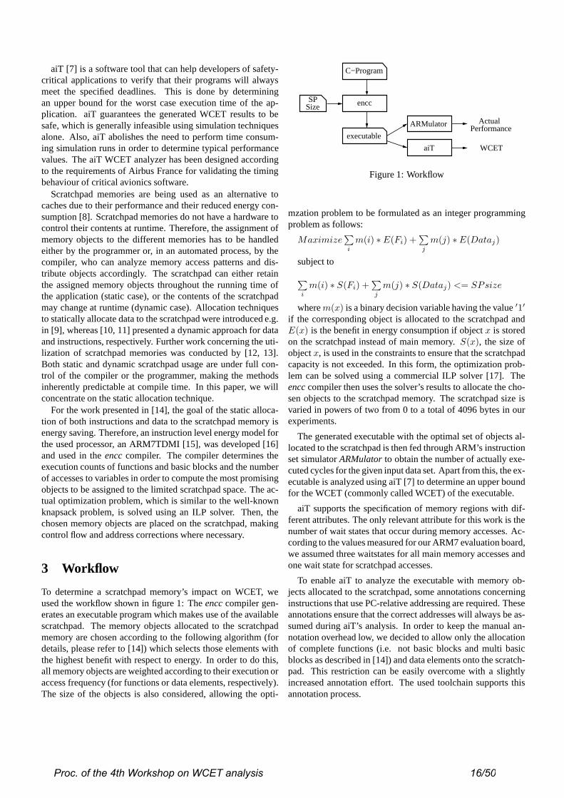
3 Workflow
To determine a scratchpad memory’s impact on WCET, weused the workflow shown in figure 1: The encc compiler gen-erates an executable program which makes use of the availablescratchpad. The memory objects allocated to the scratchpadmemory are chosen according to the following algorithm (fordetails, please refer to [14]) which selects those elements withthe highest benefit with respect to energy. In order to do this,all memory objects are weighted according to their execution oraccess frequency (for functions or data elements, respectively).The size of the objects is also considered, allowing the opti-
C−Program
encc
executable
ARMulator
aiT
PerformanceActual
WCET
SPSize
Figure 1: Workflow
mzation problem to be formulated as an integer programmingproblem as follows:
Maximize∑i
m(i) ∗ E(Fi) +∑j
m(j) ∗E(Dataj)
subject to
∑i
m(i) ∗ S(Fi) +∑j
m(j) ∗ S(Dataj) <= SPsize
where m(x) is a binary decision variable having the value ′1′
if the corresponding object is allocated to the scratchpad andE(x) is the benefit in energy consumption if object x is storedon the scratchpad instead of main memory. S(x), the size ofobject x, is used in the constraints to ensure that the scratchpadcapacity is not exceeded. In this form, the optimization prob-lem can be solved using a commercial ILP solver [17]. Theencc compiler then uses the solver’s results to allocate the cho-sen objects to the scratchpad memory. The scratchpad size isvaried in powers of two from 0 to a total of 4096 bytes in ourexperiments.
The generated executable with the optimal set of objects al-located to the scratchpad is then fed through ARM’s instructionset simulator ARMulator to obtain the number of actually exe-cuted cycles for the given input data set. Apart from this, the ex-ecutable is analyzed using aiT [7] to determine an upper boundfor the WCET (commonly called WCET) of the executable.
aiT supports the specification of memory regions with dif-ferent attributes. The only relevant attribute for this work is thenumber of wait states that occur during memory accesses. Ac-cording to the values measured for our ARM7 evaluation board,we assumed three waitstates for all main memory accesses andone wait state for scratchpad accesses.
To enable aiT to analyze the executable with memory ob-jects allocated to the scratchpad, some annotations concerninginstructions that use PC-relative addressing are required. Theseannotations ensure that the correct addresses will always be as-sumed during aiT’s analysis. In order to keep the manual an-notation overhead low, we decided to allow only the allocationof complete functions (i.e. not basic blocks and multi basicblocks as described in [14]) and data elements onto the scratch-pad. This restriction can be easily overcome with a slightlyincreased annotation effort. The used toolchain supports thisannotation process.
Proc. of the 4th Workshop on WCET analysis 16/50

4 Results
The benchmarks used to explore the impact of a scratchpad onWCET are given in table 1. They comprise two speech encod-ing and decoding algorithms from the mediabench benchmarksuite [18]. The programs were compiled with varying scratch-pad sizes, as described in the previous section. The executiontime is expected to decrease (along with the energy consump-tion) when the scratchpad capacity is increased. The effectof larger scratchpad size on average case performance and onWCET can be seen in figures 2 to 4.
Name Description
adpcm Speech encoding and decoding usingAdaptive Diff. Pulse Code Modulation
G.721 Speech encoding and decoding, referenceimplementation of the CCITT
Multi Sort Combination of sorting algorithms
Table 1: Benchmarks
0 16 32 64 128 256 512 1024 2048 40960
250500750
1000125015001750200022502500275030003250350037504000
Execution Time vs. WCET (G.721)
WCET
Execution Time
Scratchpad Size [Bytes]
Cyc
les
[x10
00]
Figure 2: Results for G.721 benchmark
The G.721 benchmark takes a little more than 2 million cy-cles to complete with our used input data on a system withonly one main memory, whereas aiT estimates the WCET forthe worst case input to be about 4 million cycles. Since it isin general not possible to determine the worst case input dataset for an arbitrary application, using a simulation approach isnot feasible to determine a guaranteed upper bound for WCET.As can be seen in figure 2, increasing the scratchpad capacitynot only improves the average execution time, but also has astrong positive effect on the WCET estimate. Where averagecase execution time is reduced to about 1,250,000 cycles fora 4k scratchpad, corresponding to a reduction of 43%, WCETreduces down to 1,650,000 cycles, which means a reduction of58% compared to the inital case with no scratchpad. Thus, theeffect on WCET is even greater than the effect on average caseexecution time.
For the Multi Sort benchmark, similar results can be ob-served. By only changing the scratchpad capacity and usingour compile-time algorithm to solve the problem of allocatingan optimal set of memory objects to the scratchpad memory,
0 16 32 64 128 256 512 1024 2048 40960
250
500
750
1000
1250
1500
1750
2000
2250
2500
2750
3000
3250
Execution Time vs. WCET (Multi_Sort)
WCET
Execution Time
Scratchpad Size [Bytes]
Cyc
les
[x10
00]
Figure 3: Results for Multi Sort benchmark
we find that the WCET decreases by about 65%, whereas theactual execution time for our used average input data only de-creases by about 50%. Without further requirements concern-ing WCET analysis (as e.g. required if a cache was used in thesystem), the use of a scratchpad memory thus shows a positiveimpact on WCET.
0 128 256 512 1024 2048 40960
50
100
150
200
250
300
350
400
450
500
Execution Time vs. WCET (adpcm)
WCET
Execution Time
Scratchpad Size [Bytes]
Cyc
les
[x10
00]
Figure 4: Results for adpcm benchmark
For the adpcm benchmark, even the initial WCET valuesare very close to the actual execution times. This seems tobe due to the fact that all execution paths within this bench-mark are very similar to the critical path. Despite this goodinitial WCET estimate, using a scratchpad can still improvethe WCET prediction: If an onchip memory of more than 512bytes is used, the difference between actual performance andWCET becomes negligible. The reductions in average case ex-ecution and WCET estimate reduce by 49% and 63%, respec-tively, highlighting the fact that WCET benefits strongly fromuse of a scratchpad memory.
One reason for the positive effect of scratchpad memo-ries is possibly due to worst case assumptions concerningpipeline stalls. In the case of a three stage pipeline (as in theARM7TDMI used in our experiments), a pipeline stall will re-quire three instructions to be fetched from memory before thenext result is generated by the CPU. If the latency for a singlememory access is three cycles, then nine additional memory
Proc. of the 4th Workshop on WCET analysis 17/50
cycles will be required to completely re-fill the pipeline (as-suming, as on our evaluation board, memory chips that do notsupport accelerated burst transfers). If, on the other hand, theused memory has a latency of only one cycle (as is the case fora scratchpad memory), then the pipeline can be filled with onlythree additional memory cycles. aiT has to assume all pos-sible pipeline stalls to be able to guarantee that the predictedWCET result is always safe. The fact that the overhead forthese pipeline stalls can be reduced by using a scratchpad mem-ory explains the good results concerning WCET.
5 Summary and Future Work
In this work we show for the first time that using scratchpadmemories in real-time systems is beneficial for WCET esti-mation. Using a known algorithm to allocate memory objects(both instructions and data) to the scratchpad memory, and acommercially available WCET analysis tool, we have shownthat the decrease of the WCET caused by scratchpad memoriesis even larger than the decrease of the average case executiontime. This is possible without any modification in the used tim-ing analysis tool. Many performance enhancing architecturalmodifications (e.g. caches) make WCET estimation a difficulttask. If scratchpads are being used, the user only needs to knowthe latency cycles of the used memories.
This work shows an additional advantage of scratchpadbased architectures beyond previously published results (whichinvestigated average case execution time and energy consump-tion). All this is feasible with a decreased complexity of WCETtools.
In the future, we will consider how scratchpad memoriescompare to cache models that are being supported in someWCET analyzers today. This comparison is not really fair,since caches require extensive support and careful analysis inWCET analysis, whereas scratchpad memories can be inte-grated at no extra analysis costs. However, caches are beingused in many systems today to improve the average perfor-mance and therefore have a practical significance.
Apart from using the energy-aware allocation algorithmfrom [14], we will also consider employing a similar techniquewhich primarily takes into account the memory objects thatlie on a program’s critical path. By reinforcing the selectionof these memory objects instead of those memory objects thatconsume most energy, the positive effect on WCET should be-come even more obvious.
6 Acknowledgement
The authors would like to thank “AbsInt” Angewandte Infor-matik GmbH for their support concerning WCET analysis us-ing the aiT framework.
References[1] Milind B. Kamble and Kanad Ghose. Analytical Energy Dissipation
Models for Low-Power Caches. In Proc. International Symposium onLow Power Electronics and Des ign, pages 143–148. ACM/IEEE, Au-gust 1997.
[2] Reinhold Heckmann, Marc Langenbach, Stephan Thesing, and ReinhardWilhelm. The Influence of Processor Architecture on the Design and theResults of WCET Tools. Proceedings of the IEEE, 91(7), July 2003.
[3] Peter Puschner and Alan Burns. A Review of Worst-Case Execution-Time Analysis. Journal of Real-Time Systems, 18(2/3):115–128, May2000.
[4] Yau-Tsun Steven Li, Sharad Malik, and Andrew Wolfe. PerformanceEstimation of Embedded Software with Instruction Cache Modeling. InProceedings of the IEEE/ACM International Conference on Computer-Aided Design, pages 380–387, November 1995.
[5] Yau-Tsun Steven Li, Sharad Malik, and Andrew Wolfe. Cache Modelingfor Real-Time Software: Beyond Direct Mapped Instruction Caches. InProceedings of the IEEE Real-Time Systems Symposium, December 1996.
[6] Thomas Lundqvist. A WCET Analysis Method for Pipelined Micropro-cessors with Cache Memories. Technical report, Dept. of Computer En-gineering, Chalmers University of Technology, June 2002.
[7] AbsInt Angewandte Informatik GmbH. aiT: Worst Case Execution TimeAnalyzers. http://www.absint.com/ait, 2004.
[8] R. Banakar, S. Steinke, B.-S. Lee, M. Balakrishnan, and P. Marwedel.Scratchpad Memory: A Design Alternative for Cache On-chip Memoryin Embedded Systems. In 10th Int. Symp. on Hardware/Software Code-sign (CODES), May 2002.
[9] P. R. Panda, N. D. Dutt, and A. Nicolau. Memory Issues in EmbeddedSystems-On-Chip. Kluwer Academic Publishers, 1999.
[10] M.Kandemir, J.Ramanujam, M.J.Irwin, N.Vijaykrishnanand I.Kadayif,and A.Parikh. Dynamic Management of Scratch-Pad Memory Space.In Proceedings of the 2001 ACM Design Automation Conference. DAC,June 2001.
[11] S. Steinke, N. Grunwald, L. Wehmeyer, R. Banakar, M. Balakrishnan,and P. Marwedel. Reducing Energy Consumption by Dynamic Copyingof Instructions onto Onchip Memory. Int. Symp. on System Synthesis(ISSS), pages 213–218, 2002.
[12] J.Ph. Diguet, S. Wuytack, F. Catthoor, and H. De Man. FormalizedMethodology for Data Reuse Exploration in Hierarchical Memory Map-pings. In ISLPED 1997 Monterey CA. ACM, August 1997.
[13] P.R.Panda, F.Catthoor, N.D.Dutt, K.Danckaert, E.Brockmeyer,C.Kulkarni, A.Vandercapelle, and P.G.Kjeldsberg. Data and mem-ory optimization techniques for embedded systems. pages 149–206,April 2001.
[14] S. Steinke, L.Wehmeyer, B.-S. Lee, and P. Marwedel. Assigning Programand Data Objects to Scratchpad for Energy Reduction. Design, Automa-tion and Test in Europe (DATE), pages 409–417, 2002.
[15] ARM Ltd. ARM7TDMI Technical Reference Manual.http://www.arm.com/pdfs/DDI0210B 7TDMI R4.pdf, 2004.
[16] S. Steinke, M. Knauer, L. Wehmeyer, , and P. Marwedel. An Accurateand Fine Grain Instruction-Level Energy Model Supporting Optimiza-tions. In Proceedings of the International Workshop - Power and TimingModeling, Optimization and Simulation, Yverdon-les-bains, Switzerland,September 2001.
[17] ILOG. CPLEX. http://www.ilog.com/products/cplex.
[18] Stephen Brown. MediaBench Home.http://cares.icsl.ucla.edu/MediaBench, 2004.
Proc. of the 4th Workshop on WCET analysis 18/50
Controlling the Influence of PCI DMA Transfers on Worst Case ExecutionTimes of Real–Time Software ∗
Jurgen Stohr Alexander von Bulow Georg FarberInstitute for Real–Time Computer Systems
Prof. Dr.–Ing. Georg FarberTechnische Universitat Munchen, Germany
{Juergen.Stohr,Alexander.Buelow,Georg.Faerber}@rcs.ei.tum.de
Abstract
The PCI Local Bus is used in all general purpose computersystems. Peripheral devices connected to this bus may performtransactions autonomously. If a processor accesses the mainmemory or performs an I/O instruction, the execution time ofthese operations depends on the working load of the PCI busand of the communication protocols being used by the chipset. In this paper the influence of the PCI Local Bus on real–time software is demonstrated. A method is presented reducingthese impacts of the PCI Local Bus on the execution time ofreal–time software. Thus accesses to PCI peripherals fromreal–time tasks behave more deterministically.
1. Introduction
When determining the worst–case execution time of real–time software, all the underlying hardware has to be taken intoaccount. Major reasons for varying execution times of soft-ware are the caches and the TLBs as the costs of a cache missare immense. If there is a miss the execution time of loading acache line from the main memory into the processor dependson the transactions being performed by the PCI peripherals. Inaddition, if a real-time task wants to perform I/O and there-fore has to access a peripheral device directly, the chip set alsoshould not be busy if deterministic computation times are fa-vored.
In most cases the behavior of the chip set is transparent tosoftware. It interconnects the processors, the main memoryand the peripheral devices. An essential part of the chip setof general purpose computers is the PCI Local Bus which isused to connect the peripheral devices to the host. As theseperipheral devices can be programmed to perform accesses to
∗The work presented in this paper is supported by the DeutscheForschungsgemeinschaft as part of a research programme on “Real-time with Commercial Off-the-Shelf Multiprocessor Systems” underGrant Fa 109/15-1.
the main memory autonomously by processing DMA trans-fers, there is a steady influence on the execution time of soft-ware.
In this paper the impacts of the PCI Local Bus on the worst–case execution time of real–time software are examined. Amethod is presented which can be used to postpone the DMAtransfers of PCI devices in order to get more deterministic ex-ecution times of real–time software. This method can be usedif a general purpose and a real–time operating system are run-ning in parallel on the same machine and real–time and nonreal–time devices are connected to PCI.
This paper is organized as follows. Section 2 gives a surveyof the PCI Local Bus being used in real–time systems. In sec-tion 3 some important facts of PCI are explained. Our methodmaking the PCI Local Bus behaving more deterministicallyis described in section 4. The advantages of this method aredemonstrated in section 5. The paper is summarized in sec-tion 6.
2. Related Work
In real–time systems, the PCI Local Bus is used to intercon-nect the various components. Examples are the RAPID [2] [6]and the SARA [3] project. However, only a few publicationsdeal with PCI: In [4] PCI connects a reconfigurable computingdevice to its hosts processor. In this paper, some performancemeasurements concerning PCI are done. Baumgartl and Hartigdiscuss in [1] PCI busmastering DMA. In contrast to the con-clusion of this paper they noticed, that to their knowledge itis impossible to give timing guarantees for DMA operationsinvolving the PCI bus.
When designing and validating a computer system for hardreal–time usage the worst case execution time (WCET) of soft-ware has to be known. There are many components of thesystem that have an influence on the WCET, for example thearchitecture of the CPU and the design of the caches. The chipset and its buses and communication protocols affect the exe-cution time, too. There exist two different approaches whenevaluating the WCET: the modelling and the measurement
Proc. of the 4th Workshop on WCET analysis 19/50

.....
Bridge DevicePCI
PCIDevice
PCIDevice
PCIDevice
MainMemoryBridgeAGP
Host Bus
PCI Bus 0
PCI Bus 1
CPU CPU CPU
PCI−to−PCI
Host
Figure 1: System Architecture
based approach. The pros and cons of each approach are dis-cussed in [5]. As the specifications of processor and chip setare often not available for public use, we have chosen the mea-surement based approach to start our work with.
3. PCI Local Bus
In state of the art computer systems, the Host Bridge inter-connects the CPUs, the Advanced Graphics Adapter (AGP),the main memory and the PCI peripherals. Figure 1 illustratesa simplified system architecture: The Host Bus connects theCPUs to the Host Bridge and the PCI Local Buses are used toconnect the peripheral devices to the Host Bridge.
3.1. Functionality
The PCI Local Bus is a multi–master bus. Every deviceis allowed to become initiator. The initiator, or bus master,initiates a transfer. The target, or slave, is the device currentlyaddressed by the initiator for the purpose of performing a datatransfer. PCI devices can access the bus autonomously withoutthe aid of a CPU. In order to avoid collisions, each initiator hasto request the bus from the PCI bus arbiter before performingany transfers.
Usually the arbiter is integrated into the PCI chip set; specif-ically, it is typically integrated into the Host Bridge. As thePCI specification does not define the scheme to be used by thePCI bus arbiter, the order the devices are accessing the bus de-pends on the chip set being used. The PCI specification onlystates that the arbiter is required to implement a fairness algo-rithm to avoid deadlocks.
As the Host Bridge acts to the PCI bus as a PCI device,it has to request the PCI bus from the arbiter like any otherdevice before becoming initiator. If a peripheral device wantsto access the main memory the Host Bridge is the target.
A PCI–to–PCI bridge provides a bridge from one PCI busto another. It works as a traffic coordinator between the two
buses. It monitors the transactions that are initiated on the twoPCI buses and decides whether or not to pass the transactionthrough the opposite PCI bus.
3.2. Burst Transfers
When performing a transfer, a peripheral device first has torequest for bus ownership as mentioned above. The transferitself is consisting of a single address phase followed by twoor more data phases. The start address and the transaction typeare issued during the address phase. The target device latchesthe start address into its address counter which is incrementedfrom one data phase to the next one. This kind of data transferis called a DMA burst transfer.
If a bus master acquires ownership of the PCI bus, it initiatesa transaction. The two most important types of transactions arelisted below:
memory transactions A device accesses the memory of an-other PCI device. If the target addresses reside in themain memory, the Host Bridge serves as target.
I/O transactions These transactions are used to access thecommand and status registers of the PCI devices. Nor-mally, I/O transactions are generated by the Host Bridge.
4. Impact of the PCI–Bus
If a PCI peripheral device performs a burst transfer access-ing the main memory, the execution of real–time software canbe delayed in two ways:
• If the CPU executing a real–time task has to access themain memory, these accesses are affected by paralleltransfers of peripheral devices. This happens if a periph-eral device initiates a DMA burst transfer accessing themain memory just before the access to the main memoryof a CPU is initiated.
• A real–time task wants to perform I/O, e.g. writing datato a hard disk, and therefore has to access a peripheraldevice. If there is a high workload on the PCI bus, theI/O transactions may be delayed. This latency dependson the arbitration scheme being used by the bus arbiter.
As the policy of the PCI arbiter depends on the chip set,it cannot be said in which order the peripheral devices are al-lowed to access the bus. If some devices have got pendingrequests, the arbiter chooses one of them. If the access to thebus is granted to a certain device, it is allowed to perform itstransfers for a certain span of time, which is specified by theLatency Timer.
Master Enable Bit The execution time of real–time soft-ware when accessing a PCI peripheral varies depending on theworkload on the PCI bus. But there is a way to configure the
Proc. of the 4th Workshop on WCET analysis 20/50

0.1
1
10
100
1000
10000
100000
1200 1400 1600 1800 2000
num
ber
of v
alue
s (lg
)
time in microseconds (usec)
300000 measured values
minimum: 1196.996 usec
maximum: 2062.412 usec
average: 1248.671 usec
Figure 2: Accesses of a CPU to main memory with con-current PCI activity
0.1
1
10
100
1000
10000
100000
1200 1400 1600 1800 2000
num
ber
of v
alue
s (lg
)
time in microseconds (usec)
300000 measured values
minimum: 1195.893 usec
maximum: 1218.476 usec
average: 1208.490 usec
Figure 3: Accesses of a CPU to main memory withoutconcurrent PCI activity
PCI Local Bus to behave more deterministically: Each periph-eral device can be prevented from becoming initiator by clear-ing the Master Enable Bit which is defined in the PCI Com-mand Register. If this bit is cleared on every peripheral devicewhich may become initiator during certain critical sections,the PCI Local Bus can be used by the Host Bridge exclusively.Thus a real–time task performing transactions across the PCIbus cannot be delayed.
The time needed to clear every Master Enable Bit dependson the number of peripheral devices connected to the bus, theactivity of each device and of the arbitration algorithm. Beforeperforming the I/O transactions needed to clear the Master En-able Bit, the Host Bridge has to arbitrate for the bus. Thislatency depends on the peripherals able to perform transac-tions. If the number of devices being able to become initiator
0.1
1
10
100
1000
10000
300 400 500 600 700 800 900
num
ber
of v
alue
s (lg
)
time in microseconds (usec)
300000 measured values
minimum: 339.041 usec
maximum: 895.856 usec
average: 654.919 usec
Figure 4: Accesses of a CPU to a PCI device with con-current PCI activity
0.1
1
10
100
1000
10000
100000
1e+06
300 400 500 600 700 800 900
num
ber
of v
alue
s (lg
)
time in microseconds (usec)
300000 measured values
minimum: 339.021 usec
maximum: 339.607 usec
average: 339.241 usec
Figure 5: Accesses of a CPU to a PCI device withoutconcurrent PCI activity
decreases, the time needed to clear the Master Enable Bit of aremaining peripheral decreases, too.
PCI–to–PCI bridges If PCI–to–PCI bridges are used, allperipherals not needed in real–time context should be put be-hind this bridge if possible. Thus only the Master Enable Bitof the bridge has to be cleared. Then the bridge ignores allmemory and I/O transactions detected on the secondary side.In order to minimize the time needed to clear the Master En-able Bit of each relevant PCI device, a few guidelines can bestated:
• The devices causing the heaviest workload should be dis-abled first.
• All non-RT relevant devices should be grouped behind a
Proc. of the 4th Workshop on WCET analysis 21/50

bridge, thus only the bridge has to be disabled.
• The devices needed in RT context should be plugged intothe PCI bus nearest to the Host Bridge.
• Only the devices able to initiate DMA burst transfersshould be disabled. The Master Enable Bits of periph-eral devices which are not used by the operating systemor which only act as slaves need not to be cleared.
5. Results
We have performed some measurements in order to studythe effects when the Master Enable Bits are cleared:
Accesses to Main Memory These measurements havebeen taken on a Dual PII machine using the Intel 440FX chipset. On one CPU a real–time task was started which accessedthe main memory performing 2048 read and write accesses.Attention has been payed not to cache the memory accesses.The second CPU was kept in an idle loop not affecting themeasurement. The results of this measurement are illustratedin figure 2 and 3. If there is PCI activity in parallel, the execu-tion time to perform the 2048 accesses varies by 72%; if thereis not any PCI activity the execution times are varying by 2%.
Accesses to PCI Devices In the following measurementsthe time needed to access a PCI peripheral from a real–timetask are examined. These measurements have been performedon a Dual Athlon machine using the AMD 760MPX chip set.The real–time task performed 1024 read accesses to a PCI pe-ripheral using memory–mapped I/O, whereby always the samememory–mapped address was used in order to avoid bursttransfers. The other processor was kept in an idle loop dur-ing each measurement. The results of this measurements areshown in figure 4 and 5. If the 1024 accesses are done withPCI activity in parallel, the execution time varies by 164%; ifthe Master Enable Bits are cleared, the execution time is nearlyconstant.
Time needed to enter the deterministic state We havealso measured the time needed to clear the Master Enable Bitof the relevant PCI device — a PCI–to–PCI bridge — of theDual Athlon. In parallel to each measurement the host wasbusy, performing network and disk I/O heavily. The timeneeded to clear the Master Enable Bit varies between 1.41 mi-croseconds and 5.94 microseconds.
6. Conclusion
As the PCI peripherals are allowed to initiate transactionsautonomously, there is an influence on the execution time ofreal–time software due to DMA burst transfers. These trans-fers affect the time needed to access the main memory from aCPU leading to varying execution times of software. On the
other side, if a real–time task wants to perform I/O, the accesstime depends on the current workload on the PCI Local Bus.
In this paper a method is presented which makes accessesfrom a CPU across the PCI Local Bus behaving more deter-ministically. When switching to real–time context the bus maybe configured by clearing the Master Enable Bit of relevant de-vices. Thus only the Host Bridge is allowed to become initiatorand all peripherals are only acting as slaves.
This method is useful for real–time systems accomplishinga lot of I/O. When estimating the WCET of specific code per-forming I/O, the time needed to enter the deterministic statehas to be considered. The measurement based approach is use-ful when determining the WCET of a given system. However,hard– and software has to be configured in a way which leadsto deterministic execution times.
References
[1] Robert Baumgartl and Hermann Hartig. Efficient Commu-nication Mechanisms for DSP-based Multimedia Acceler-ators. In In the proceedings of ICSPAT’97, San Diego,September 1997.
[2] Franz Fischer, Thomas Kolloch, Annette Muth, and GeorgFarber. A configurable target architecture for rapid proto-typing high performance control systems. In Hamid R.Arabnia et al., editors, Proc. of the International Confer-ence on Parallel and Distributed Processing Techniquesand Applications (PDPTA’97), volume 3, pages 1382–1390, Las Vegas, Nevada, USA, June 30 – July 3 1997.
[3] L. Lindh, T. Klevin, and J. Furunas. Scalable Architec-tures for Real-Time Applications - SARA. In SwedishNational Real–Time Conference SNART’99, Linkoping,Sweden, August 1999.
[4] Laurent Moll and Mark Shand. Systems PerformanceMeasurement on PCI Pamette. In Kenneth L. Pocekand Jeffrey Arnold, editors, IEEE Symposium on FPGAsfor Custom Computing Machines, pages 125–133, LosAlamitos, CA, 1997. IEEE Computer Society Press.
[5] Stefan M. Petters. Worst Case Execution Time Estimationfor Advanced Processor Architectures. PhD thesis, Insti-tute for Real–Time Computer Systems, Technische Uni-versitat Munchen, September 2002.
[6] Stefan M. Petters, Annette Muth, Thomas Kolloch,Thomas Hopfner, Franz Fischer, and Georg Farber. TheREAR framework for emulation and analysis of embed-ded hard real–time systems. In Proc. of the 10th IEEEInt. Workshop on Rapid Systems Prototyping (RSP’99),pages 100–107, Clearwater, Florida, June 16–18 1999.IEEE Computer Society Press.
[7] Tom Shanley and Don Anderson. PCI System Architec-ture. Addison–Wesley Publishing Company, 3 edition,1995.
Proc. of the 4th Workshop on WCET analysis 22/50

Synergetic effects in cache related preemption delays
Jan Staschulat, Rolf ErnstInstitute of Computer and Communication Network Engineering (IDA)Technical University of Braunschweig, D-38106 Braunschweig, Germany
{staschulat,ernst}@ida.ing.tu-bs.de
Abstract
Cache prediction for preemptive scheduling is an openissue despite its practical importance. First analysis ap-proaches use simplified models for cache behaviour orthey assume simplified preemption and execution scenar-ios that seriously impact analysis precision. We presentan analysis approach for m-way associative caches whichconsiders multiple executions of processes and preemp-tion scenarios for static priority periodic scheduling. Theresults of our experiments show that caches introduce astrong and complex timing dependency between processexecutions that are not appropriately captured in thesimplified models.
1 Introduction and motivation
Caches are needed to increase processor performance butthey are hard to use in real-time systems because of theircomplex behaviour. While it is already difficult to de-termine cache behaviour for a single process, it becomesreally complicated if preemptive process scheduling is in-cluded. Preemptive process scheduling means that pro-cess execution can be interrupted by higher priority pro-cesses. In this case, cache improvements can be stronglydegraded by frequent exchange of cache blocks.
There are several approaches to make caches more pre-dictable and efficient. One approach is to lock frequentlyused cache lines [9] [3]. The advantage is that cache linesdo not have to be reloaded after interrupts and betweenconsecutive executions of the same process. Also, cachebehaviour becomes (partly) orthogonal for processes andtherefore more predictable. In [4] process layout tech-niques are suggested which aim at minimising the inter-process interference in the instruction cache. While lockstrategies and layout techniques are certainly a very use-ful add-on to improve cache predictability and efficiency,they do not solve the general cache behaviour problem.
Recent approaches use data flow analysis of the pre-empted and preempting process to bound the numberof replaced cache blocks [7] [8]. However, these ap-proaches model only a single process activation assumingan empty cache at process start. If a process is pre-empted several times the total number of cache blocks
replaced drops, because a cache block of preempted pro-cess can only be replaced once [11]. Such preemptionscenarios are not considered in classical cache relatedpreemption delay (CRPD) analysis.
This paper is organised as follows. Sec. 2 reviews re-lated work. In Sec. 3 we present a new analysis approachto determine the CRPD for m-way associative instruc-tion caches which considers multiple executions of pro-cesses as well as preemption scenarios. We show theresults in Sec. 4 and list open issues in Sec. 5 before weconclude in Sec. 6.
2 Related work
The data flow analysis by [7] determines the CRPD whena process τ1 preempts process τ0 by intersecting the num-ber of useful CBs of τ0 and with the number of used CBsof τ1 assuming an empty cache at process start. Then,a complex analysis follows analysing all possible com-binations of preemptions. The number of preemptionsis determined by integer linear programming (ILP) andprocess phasing based on worst case and best case re-sponse time (BCRT) of processes. However, the BCRTanalysis is a complicated problem where only approxi-mative solutions have been proposed for the general case[5]. The important case of multiple process executions isnot considered and multiple preemptions are simplifiedby multiplying the maximum CRPD cost by the numberof preemptions. For direct mapped instruction caches[8] refine the data flow analysis of [7] by modelling thecache content as a state instead of a set. All possiblecache states of the preempting and preempted processare intersected to find the maximum CRPD. Preemp-tion scenarios are not considered and an empty cache isassumed at process start. Further on, real measurementsare described in [10]. Pre-runtime scheduling heuristicswhich take the effects of process switching on processorcache into account have been presented in [6]. However,only non-preemptive scheduling based on earliest dead-line first strategies is considered which is much easierthan the preemptive case.
Current approaches either model only the number andcost of preemptions for a single process execution or thecache effects of multiple process execution without pre-
Proc. of the 4th Workshop on WCET analysis 23/50
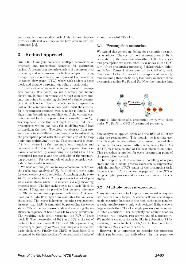
emptions, but none models both. Only the combinationprovides sufficient accuracy as we have seen in own ex-periments [11].
3 Refined approach
Our CRPD analysis considers multiple activations ofprocesses and preemption scenarios for instructioncaches. A preemption scenario consists of one preemptedprocess τi and of a process τj which preempts τi duringa single execution n times. We represent the process byits control flow graph (CFG), where each node is a basicblock and assume a preemption point at each node.
To reduce the exponential combinations of n preemp-tion points (CFG nodes) we use a branch and boundalgorithm. It first determines the n most expensive pre-emption points by analysing the cost of a single preemp-tion at each node. Then it continues to compare thecost of the combinations of two nodes until the cost Cn
for a preemption scenario with n nodes is found. Thealgorithms bounds at a combination if the current costplus the cost for future preemptions is smaller than Cn.For sequential code this is straight forward, but for npreemptions within loop body this modelling would leadto unrolling the loop. Therefore we abstract from pre-emption points of different loop iterations by estimatingthe preemption point with the maximum cost of the loopbody and multiplying it by n. This estimation is exactif I ≥ n, where I is the maximum loop iterations andconservative if I < n. The cost Cn of a preemption sce-nario is calculated by considering the useful CBs of thepreempted process τi and the used CBs of the preempt-ing process τj . For the analysis of each preemption costa data flow model is needed.
We base our analysis for m-way associative caches onthe cache state analysis of [8]. But define a cache statefor each cache set with m blocks. A reaching cache stateRCSB at a basic block B of a process is the set of pos-sible cache states when B is reached via any incomingprogram path. The live cache states at a basic block B,denoted LCSB , are the possible first memory referenceto CBs via any outgoing program path from B. A leastfixed point data flow algorithm computes the values ofthese sets. The cache behaviour including replacementstrategy (e.g. LRU) is simulated by preloading the cachestate RCS of the predecessor node and executing the in-struction sequence of basic block B by cache simulation.The resulting cache state represents the RCS of basicblock B. The intersection of RCS and LCS is the set ofuseful CBs at basic block B. The used CBs of preemptingprocess τj is given by RCSend, assuming end is the lastbasic block of τj . Finally, the CRPD at basic block B iscomputed by the intersection of the used cache blocks of
τj and the useful CBs of τi.
3.1 Preemption scenarios
We extend this general modelling for preemption scenar-ios as follows. The cost of the first preemption at Bk iscalculated by the data flow algorithm of [8]. For a sec-ond preemption we insert after Bk n nodes in the CFGof τi, if the preempting process τj finishes with n differ-ent RCSs. Figure 1 shows part of the CFG of τi withfour basic blocks. To model a preemption at node B3,and assuming three RCSs at τj last node, we insert threepreemption nodes P1, P2 and P3. Now the iterative data
B2 B3
B4
B1
B2 B3
B4
B1
Preemption
P1 P2 P3
Figure 1: Modelling of a preemption by τj with threenodes P1, P2 P3 in CFG of preempted process τi
flow analysis is applied again and the RCS of all othernodes are recalculated. This models the fact that use-ful CBs might be overwritten by a preemption and thuscannot be displaced again. After recalculating the RCSsthe CRPD is recalculated at the next preemption point.This procedure is applied for every preemption point ofthe preemption scenario.
The complexity of this accurate modelling of n pre-emptions for a single process execution is exponentialwith the number of RCS states of the preempting task,because the n RCS states are propagated in the CFG ofthe preempted process and increase the number of cachestates.
3.2 Multiple process execution
Many automotive control applications consist of sequen-tial code without loops. A cache will not speed up asingle execution because of the high cache miss penalty.A cache architecture is only well designed if the cache islarge enough that CBs of a single process can be reusedin later executions. For simplicity we assume that noprocesses run between two activations of a process τi.We model a warm cache cache like in Subsection 3.1 byinserting n nodes in the CFG before the first node for ndifferent RCSend sets of process τi.
However, it is important to consider the processeswhich run between two activations. In this paper we
Proc. of the 4th Workshop on WCET analysis 24/50
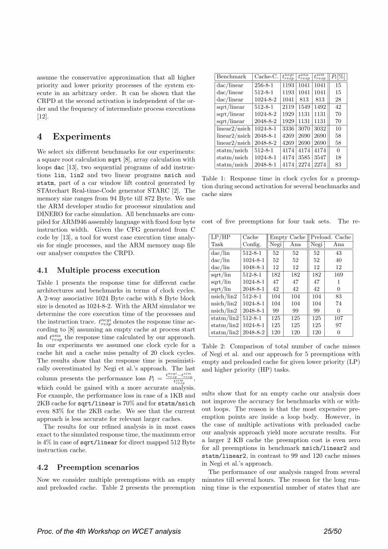
assume the conservative approximation that all higherpriority and lower priority processes of the system ex-ecute in an arbitrary order. It can be shown that theCRPD at the second activation is independent of the or-der and the frequency of intermediate process executions[12].
4 Experiments
We select six different benchmarks for our experiments:a square root calculation sqrt [8], array calculation withloops dac [13], two sequential programs of add instruc-tions lin, lin2 and two linear programs nsich andstatm, part of a car window lift control generated bySTAtechart Real-time-Code generator STARC [2]. Thememory size ranges from 94 Byte till 872 Byte. We usethe ARM developer studio for processor simulation andDINERO for cache simulation. All benchmarks are com-piled for ARM946 assembly language with fixed four byteinstruction width. Given the CFG generated from Ccode by [13], a tool for worst case execution time analy-sis for single processes, and the ARM memory map fileour analyser computes the CRPD.
4.1 Multiple process execution
Table 1 presents the response time for different cachearchitectures and benchmarks in terms of clock cycles.A 2-way associative 1024 Byte cache with 8 Byte blocksize is denoted as 1024-8-2. With the ARM simulator wedetermine the core execution time of the processes andthe instruction trace. tnegi
resp denotes the response time ac-cording to [8] assuming an empty cache at process startand tana
resp the response time calculated by our approach.In our experiments we assumed one clock cycle for acache hit and a cache miss penalty of 20 clock cycles.The results show that the response time is pessimisti-cally overestimated by Negi et al.’s approach. The last
column presents the performance loss Pl = tnegiresp−tsim
resp
tsimresp
,which could be gained with a more accurate analysis.For example, the performance loss in case of a 1KB and2KB cache for sqrt/linear is 70% and for statm/nsicheven 83% for the 2KB cache. We see that the currentapproach is less accurate for relevant larger caches.
The results for our refined analysis is in most casesexact to the simulated response time, the maximum erroris 4% in case of sqrt/linear for direct mapped 512 Byteinstruction cache.
4.2 Preemption scenarios
Now we consider multiple preemptions with an emptyand preloaded cache. Table 2 presents the preemption
Benchmark Cache-C. tnegiresp tana
resp tsimresp Pl[%]
dac/linear 256-8-1 1193 1041 1041 15dac/linear 512-8-1 1193 1041 1041 15dac/linear 1024-8-2 1041 813 813 28
sqrt/linear 512-8-1 2119 1549 1492 42sqrt/linear 1024-8-2 1929 1131 1131 70sqrt/linear 2048-8-2 1929 1131 1131 70
linear2/nsich 1024-8-1 3336 3070 3032 10linear2/nsich 2048-8-1 4269 2690 2690 58linear2/nsich 2048-8-2 4269 2690 2690 58
statm/nsich 512-8-1 4174 4174 4174 0statm/nsich 1024-8-1 4174 3585 3547 18statm/nsich 2048-8-1 4174 2274 2274 83
Table 1: Response time in clock cycles for a preemp-tion during second activation for several benchmarks andcache sizes
cost of five preemptions for four task sets. The re-
LP/HP Cache Empty Cache Preload. CacheTask Config. Negi Ana Negi Ana
dac/lin 512-8-1 52 52 52 43dac/lin 1024-8-1 52 52 52 40dac/lin 1048-8-1 12 12 12 12
sqrt/lin 512-8-1 182 182 182 169sqrt/lin 1024-8-1 47 47 47 1sqrt/lin 2048-8-1 42 42 42 0
nsich/lin2 512-8-1 104 104 104 83nsich/lin2 1024-8-1 104 104 104 74nsich/lin2 2048-8-1 99 99 99 0
statm/lin2 512-8-1 125 125 125 107statm/lin2 1024-8-1 125 125 125 97statm/lin2 2048-8-2 120 120 120 0
Table 2: Comparison of total number of cache missesof Negi et al. and our approach for 5 preemptions withempty and preloaded cache for given lower priority (LP)and higher priority (HP) tasks.
sults show that for an empty cache our analysis doesnot improve the accuracy for benchmarks with or with-out loops. The reason is that the most expensive pre-emption points are inside a loop body. However, inthe case of multiple activations with preloaded cacheour analysis approach yield more accurate results. Fora larger 2 KB cache the preemption cost is even zerofor all preemptions in benchmark nsich/linear2 andstatm/linear2, in contrast to 99 and 120 cache missesin Negi et al.’s approach.
The performance of our analysis ranged from severalminutes till several hours. The reason for the long run-ning time is the exponential number of states that are
Proc. of the 4th Workshop on WCET analysis 25/50

propagated after inserting a preemption node.
5 Open issues
The key ideas of our our approach is a sophisticated anal-ysis of preemption scenarios and consideration of cachelines from earlier process executions. While first resultsshow the benefits, we think that further work is required:
• to analyze the set of processes which run betweentwo process activations depending on scheduling al-gorithms
• to analyse CRPD for real-time systems with inter-rupts
• to improve practical applicability by developing lesscomplex analysis algorithms
• to study the effects for data caches
6 Conclusion
In this paper we have extended the approach of [8] toconsider multiple process activations and preemptionscenarios for m-way associative instruction caches. Theresults with a realistic processor architecture show thatcache effects lead to process interdependencies which caneasily outweigh individual process execution times. Suchcases are not covered by the classical performance anal-ysis approaches which are based on individual processexecution times plus independent blocking times (e.g.[1]). However, the complexity of the proposed analyis isexponential with the number of cache states of the pre-empting process. Future research is necessary to developless complex algorithms.
Applications with loops behave better also in otherapproaches. However, for automotive control applica-tions linear code is very important (e.g. Matlab gener-ated code). Here current approaches result high overes-timations. On the other hand, cache parameters havea significant influence on process interdependence. Wecan therefore conclude that cache design should receivemaximum attention in embedded system design, use pro-cess systems as benchmarks rather than individual pro-cesses to consider multiple process activation and thatnew models and approaches are needed for performanceanalysis of systems with caches.
References
[1] G. Buttazzo. Hard Real-Time Computing Systems.Norwell, MA: Kluwer, 1997.
[2] C-Lab. Wcet benchmarks. http://www.c-lab.de/home/de/download.html.
[3] Marti Campoy, A. Perles Ivars, and J. V. Busquets-Mataix. Static use of locking caches in multitaskpreemptive real-time systems. In IEEE Real-TimeEmbedded System Workshop, December 2001.
[4] Anupam Datta, Sidharth Choudhury, AnupamBasu, Hiroyuki Tomiyama, and Nikil Dutt. Sat-isfying timing constraints of preemptive real-timetasks through task layout technique. In Proceedingsof 14th IEEE VLSI Design, pages 97–102, January2001.
[5] William Henderson, David Kendall, and AdrianRobson. Improving the accuracy of scheduling anal-ysis applied to distributed systems computing min-imal response times and reducing jitter. Real-TimeSystems, 20(1):5–25, 2001.
[6] Daniel Kastner and Stephan Thesing. Cache sen-sitive pre-runtime scheduling. In ACM SIGPLANWorkshop on Languages, Compilers and Tools forEmbedded Systems, volume 1474 of Lecture Notes inComputer Science, pages 131–145. Springer, 1998.
[7] Chang-Gun Lee, Kwangpo Lee, Joosun Hahn,Yang-Min Seo, Sang Lyul Min, Rhan Ha, Seong-soo Hong, Chang Yun Park, Minsuk Lee, andChong Sang Kim. Bounding cache-related preemp-tion delay for real-time systems. IEEE Transactionson software engineering, 27(9):805–826, November2001.
[8] Hemendra Sigh Negi, Tulika Mitra, and AbhaikRoychoudhury. Accurate estimation of cache-related preemption delay. In CODES+ISSS’03,Newport Beach, California, USA, October 1-3 2003.
[9] Isabelle Puaut and David Decotigny. Low-complexity algorihtms for static cache locking inmultitasking hard real-time systems. In Proceed-ings of the 23rd IEEE Real-Time Systems Sympo-sium (RTSS’02), 2002.
[10] Filip Sebek. Instruction cache memory issues inreal-time systems. Licentiate Thesis, MalardalenUniversity, Sweden, 2002.
[11] Jan Staschulat and Rolf Ernst. Cache effects inmulti process real-time systems with preemptivescheduling. Technical report, IDA, TU Braun-schweig, Germany, November 2003.
[12] Jan Staschulat and Rolf Ernst. Crpd independencefor multiple process execution. Technical report,IDA, TU Braunschweig, March 2004.
[13] Fabian Wolf. Behavioral Intervals in EmbeddedSoftware. Kluwer Academic Publishers, 2002.
Proc. of the 4th Workshop on WCET analysis 26/50

Component-wise Instruction-Cache Behavior Prediction– Extended Abstract –
Abdur Rakib∗
Max-Planck Institut fur Informatik
Saarbrucken, Germany
Oleg Parshin, Stephan Thesing, Reinhard Wilhelm†,
{oleg, thesing, wilhelm}@cs.uni-sb.de
FR Informatik, Universitat des Saarlandes
Saarbrucken, Germany
Abstract
The precise determination of worst-case executiontimes (WCETs) for programs is mostly being performedon linked executables, since all needed information andall machine parameters influencing cache performanceare available to the analysis. This paper describeshow to perform a component-wise prediction of theinstruction-cache behavior guaranteeing conservativeresults compared to an analysis of a linked executable.This proves the correctness of the method based on aprevious proof of correctness of the analysis of linkedexecutables. The analysis is described for a general A-way set associative cache. The only assumption is thatthe replacement strategy is LRU.
1 Introduction
So far, WCET-determination methods mostly work onfully linked executables, since all machine-level infor-mation about allocation is fixed and available. Thispaper presents a method for component-wise analy-sis of the cache behavior, thus supporting incremen-tal program development. This method uses the no-tion of cache-equivalence of memory allocations to ex-press that one allocation of a module in the memory willdisplay exactly the same cache behavior as the equiva-lent one. This equivalence is exploited to influence thelinker, which can choose between several equivalent al-locations when placing a module into the executable.The overall picture is the following:
1. A set of modules making up the real-time programis given. Cyclic calling dependencies are assumedto exist only inside modules, not between modules.Thus, the module dependence graph representinginter-module call relations is acyclic.
∗Supported by the IMPRS (International Max-Planck ResearchSchool for Computer Science)
†Research reported here is supported by the transregional researchcenter AVACS (Automatic Verification and Analysis of Complex Sys-tems) of the DFG (Deutsche Forschungsgemeinschaft)
2. A bottom-up module-wise analysis computes asound approximation to the cache contents at allprogram points of all modules taking into accountsafe upper approximations of the cache damagesof called external functions. The results of themodule-wise analysis are combined conservativelywith respect to an (in general more precise) analy-sis of a linked executable.
2 Cache Memory Architectures
A cache can be characterized by three major parame-ters:
cache size s is the total size of the cache, i.e. the num-ber of bytes it may contain.
line size l (also called block size) is the number ofcontiguous bytes that are transferred from mem-ory on a cache miss. The cache can hold at mostn = s/l blocks.
associativity A is the number of cache locations wherea particular memory block can reside. The cachecontains η = n/A sets.
If a block can reside in exactly A locations, then thecache is called A-way associative. If a block can residein any cache location (A = n), then the cache is calledfully associative. If a block can reside in exactly onelocation (A = 1), then it is called direct mapped. If ablock can reside in exactly A locations, then the cacheis called A-way associative.
In the case of an associative cache, a cache line has tobe selected for replacement when the cache is full andthe processor requests further data. This is done accord-ing to the replacement strategy. Common strategies areLRU (Least Recently Used), FIFO (First In First Out),and random.
In this paper we consider A-way set associative cachewith LRU replacement strategy. Detailed formal de-scription of the cache semantics can be found in [1].
Proc. of the 4th Workshop on WCET analysis 27/50

Compiler
Several object-modules
CFG Builder
User-annotated several
source files (C, C++, ...)
Evaluation
Cache classification
Classification
Classification
Classification
PAGProgramAnalyzerGenerator
analysis.optlaanalysis.set
Static Analysis
Cache Analysis
classification for thecomplete program
Compositional cache
Mi
M1, M2, . . ., Mn for M1
for M2
for Mn
(ah, am, nc)
Figure 1: The Structure of Analysis
3 The Analysis Framework
As input to our analysis framework (c.f. Figure 1) wehave a set of object modules that are yet to be linked toform an executable. We also assume, that the user pro-vides additional information, such as number of loopiterations, upper bound for recursions etc. A parserreads the object modules and reconstructs the controlflow graph for each module [8]. Nodes of the controlflow graph represent basic blocks. For each basic blockit is known which memory blocks it references.
Analysis results are computed using Abstract In-terpretation [2]. The collecting semantics of a mod-ule is approximated from above using abstract cachestates [10].
We distinguish two kinds of analyses. The mustanalysis determines a set of memory blocks that arein the cache at a given program point whenever execu-tion reaches this point. The may analysis determines allmemory blocks that may be in the cache at given pro-gram point. The latter analysis is used to determine theabsence of memory blocks in the cache.
The analyses are used to classify the memory refer-ences into always hit, always miss, or non-classified [1].
Termination of analyses is guaranteed [3].
4 Notion of Equivalence
Our aim is to ensure that the results of cache behavioranalysis obtained at module level can be combined in aconservative way with respect to the results of an anal-ysis of a linked executable. The relative and absoluteaddress spaces of a module before and after linking, re-spectively, will in general be different. Consequently,the cache behavior of a module may be different in twodifferent address spaces.
We perform cache analysis for each module usingavailable relative address information and a fixed map-ping of relative addresses of an object module to sets.
This section is concerned with the conditions underwhich the different allocations of blocks will displayequivalent cache behavior (in the sense of number ofcache hits/misses, not exact content of the cache).
4.1 Equivalent memory allocation withrespect to the fixed set mapping
Suppose a set of modules M1, M2, . . . , Mp forms a pro-gram. Each module consists of the set {mi
0, . . . , mi
ki}
of memory blocks1. A linker combines these modulesin the sequence M1, M2, . . . , Mp. We assume that allobject modules are created with base address 0. Ac-cording to this assumption, in each module Mi theblock mi
0 is mapped to the first set of the cache.
A question arises when we consider a linked exe-cutable, whether the absolute address in the executable,which corresponds to a relative address inside the mod-ule, will be mapped to the same set. Since linkers onlyshuffle segments of object modules but do not rearrangetheir internals, all the internal memory addresses be-come offsets from the new base address of the modules.
Since the number of the set to which block mi ismapped is determined as (i mod η) [3], two memoryblocks are mapped to the same set, if the difference q
between their addresses is a multiple of (η · l), becauseeach block has the size of l bytes.
In order to preserve a fixed mapping of addresses formodule M1, the executable has to be created with sucha base address q. The base addresses of the modulesM2, . . . , Mp depend on the sum of the sizes of previ-ous modules. To preserve the fixed mapping for thesemodules, some wasted space εi between them has to beadded, such that the base address of each module willbe a multiple of (η · l).
1Each memory block has the size of a cache line.
Proc. of the 4th Workshop on WCET analysis 28/50

4.2 Conservative Cache-Behavior Analy-sis
In order to combine the results of module-wise analysisconservatively with respect to the analysis of a linkedexecutable, we choose a placement of modules accord-ing to Section 4.1, i.e., the absolute base address of eachmodule should be a multiple of (η · l).
5 Proposed Analysis Method
As input for the analysis we have a directed acyclicinter-module dependency graph where vertices repre-sent modules and edges represent call relations be-tween modules. Our analysis is based on a bottom-up approach, starting from modules which are not de-pendent on any other module in this graph (i.e., withoutdegree = 0). At each stage (for each module) theproduced results are kept in a special data structure sothat analysis results of a module will be available for itscalling modules.
5.1 Module-wise Cache Analysis
We analyze cache behavior for each procedure using theframework from Section 3 separately in the two follow-ing call contexts: (i) local call – a call between twoprocedures in the same module; and (ii) external call –a call between two procedures in the different modules.In the last case we combine at the return point the anal-ysis result of the caller with the analysis result of thecallee.
During the analysis of a procedure we assume thatcache is initially empty for the must analysis and every-thing may be in the cache for may analysis.
The analysis for modules, which have calls to othermodules (i.e, with outdegree 6= 0) uses the pre-computed information of its called modules, wheneverneeded at the calling points. Since the cache contentsof the calling module will be changed according to thecalled module’s cache information, we have to considerthe cache damages due to calls to the external proce-dures. In the following subsection we describe how tohandle such cache effects during calls between mod-ules.
5.2 Cache Damage Analysis
The aim of the cache damage analysis is to provide thecorrect information about the bounds of replacements ina particular set, i.e. to determine an upper-bound for thereplacements occurring in a particular set for the mustanalysis, and a lower-bound for the number of replace-ments for the may analysis.
Let us consider must analysis. The elements of eachset of the caller’s cache contents are age by the upperbound of replacements in the same set of the callee’scache, and the elements of this set in the callee’s cacheretain their age during the cache damage update (cf. for-mal cache semantics in [1]).
If before the call some memory block m is in thecaller’s cache set f with age x, and the upper boundof replacements in this set due to the call is a, then thisblock will survive after the call if x + a 6 A − 1.
A procedure may be also called from inside a loop ofanother procedure. If some block m is in the callee’scache at the return point with the age x, then it will bein the caller’s cache after return. Since the procedure iscalled inside a loop, this block may survive in the cacheduring all following iterations, and be in the caller’scache with the age y before the call. If y + a 6 A − 1then this block will survive during the call and be in thecaller’s cache with the age z = y + a. Hence, theremay exist multiple copies of the block m in the sameset with different ages. In order to avoid such a situa-tion we flush all callee’s memory blocks which are inthe caller’s cache before the call.
5.3 Properties of the Method
The following steps are followed during the analysisof a module: (i) Construct the control flow graph foreach procedure, (ii) identify the local and the externalcalls, (iii) analyze all possible paths considering localand external calls of a procedure, (iv) update the cacheinformation according to the call contexts using cache-damage analysis result, and (v) store the cache analy-sis information for each procedure in the correspondingdata structure.
The analysis result of the complete program is thecomposition of the analysis results of all the modules.We have the following properties of the method.
5.3.1 Termination of the analysis
Termination of the may and must analysis is guaran-teed. Cache damage analysis terminates, since the do-main is finite, update functions are monotone, and thejoin functions are monotone, associative and commuta-tive (cf. full version of this paper).
5.3.2 The results of the module-wise analysis areconservative
Our analysis is based on a bottom-up approach and dur-ing the analysis of each procedure we take safe initialapproximations according to Section 5.1. Therefore, wecan conclude the following theorem:
Proc. of the 4th Workshop on WCET analysis 29/50
Theorem 1 The results of component-wise cache be-havior prediction are conservative to an analysis resultsof a linked executable, assuming the equivalent moduleplacement according to Section 4.1.
For the sake of space, we omit the proof of the theo-rem. The proof can be found in the full version of thepaper.
5.3.3 Maximum wasted memory space
We have seen in Section 4.1.7.1 that some memoryspace is wasted due to the equivalent memory alloca-tion w.r.t. the fixed set mapping. The wasted memoryspace in the worst case is (η · l − 1) · (p − 1).
6 Related Work
Most of the research on precise cache-behavior predic-tion is being performed on fully linked executables.
The work [4] propose a compositional instruction-cache behavior prediction. Their goal is to decreasethe analysis effort by splitting the analysis into severalphases, a module-level analysis, preprocessing calls,and a compositional analysis using this information.The motivation comes from the claim that only smallprograms can be analyzed by the traditional methods.However, as shown in [9] these methods realized incommercially available tools are in routine use in theaeronautics and also in the automotive industry. Theirmethod needs the availability of all modules, while oursanalyzes modules as they are compiled and combinesthe analysis results in a conservative way. A researchgroup at the Laboratory of Embedded Systems Inno-vation and Technology (LIT) described in [5] a frame-work, PERF, which works with the object code gen-erated by the integrated tools in order to determineexecution-time limit estimations for functions that com-pose a real-time system. Their cache behavior predic-tion method is based on the extended timing schemataproposed by [6, 7].
7 Conclusions
We have presented a technique for predicting the cachebehavior for A-way set associative instruction cachescomponent-wise. Given a set of object code-modules,a parser reads the object code-modules and reconstructsthe control flow. The cache analysis technique worksin a bottom-up way starting from minimal modules ofthe module dependency graph. The analysis computesa sound approximation to the cache contents at all pro-gram points of all modules taking safe upper approxi-mations of the cache damages of called external func-tions into account. The analysis results can be com-
bined in a conservative way with respect to an analysisof a fully linked executable.
References
[1] Martin Alt, Christian Ferdinand, Florian Martin,and Reinhard Wilhelm. Cache Behavior Predic-tion by Abstract Interpretation. In Proceedings ofthe Third International Symposium on Static Anal-ysis, pages 52–66. Springer-Verlag, 1996.
[2] P. Cousot and R. Cousot. Abstract interpretationframeworks. Journal of Logic and Computation,2(4):511–547, 1992.
[3] Christian Ferdinand. Cache Behavior Predictionfor Real-Time Systems. PhD thesis, Saarland Uni-versity, 1997.
[4] Kaustubh S. Patil. Compositional Static CacheAnalysis Using Module-Level Abstraction. Mas-ter’s thesis, North Carolina State University, 2003.
[5] Douglas Renaux, Joao Goes, and Robson Lin-hares. WCET Estimation from Object Code Im-plemented in the PERF Environment. In 2nd Inter-national Workshop on Worst-Case Execution TimeAnalysis (Satellite Event to ECRTS’02), pages 28–35, Technical University of Vienna, Austria, June18, 2002.
[6] Lim S-S et al. An Accurate Worst-Case Tim-ing Analysis for RISC Processors. In IEEE Real-Time Systems Symposium, pages 97–108, Decem-ber 1994.
[7] Min S.L et al. An Accurate Instruction CacheAnalysis Technique for Real-time Systems. InProceedings of the Workshop on Architectures forReal-time Applications, April 1994.
[8] Henrik Theiling. Extracting Safe and Precise Con-trol Flow from Binaries. In Proceedings of the 7thConference on Real-Time Computing Systems andApplications, Cheju Island, South Korea, 2000.
[9] Stephan Thesing et. al. An AbstractInterpretation-Based Timing Validation ofHard Real-Time Avionics Software Systems. InProceedings of the 2003 International Conferenceon Dependable Systems and Networks (DSN2003), pages 625–632. IEEE Computer Society,June 2003.
[10] Reinhard Wilhelm. Why AI + ILP is good forWCET, but MC is not, nor ILP alone. In Pro-ceedings of the Fifth International Conference onVerification, Model Checking and Abstract Inter-pretation, Venice, Italy, January 2004.
Proc. of the 4th Workshop on WCET analysis 30/50

A Distributed WCET Computation Scheme for Smart Card
Operating Systems
Nadia Bel Hadj Aissa, Christophe Rippert, Damien Deville, Gilles Grimaud
IRCICA/LIFL, Univ. Lille 1, UMR CNRS 8022INRIA Futurs, POPS research group∗
{Nadia.Bel-Hadj-Aissa,Christophe.Rippert,Damien.Deville,Gilles.Grimaud}@lifl.fr
1 Introduction
Smart card operating systems have to face very hard constraints in terms of available memory space andcomputing power. Nonetheless, the specifications of most smart card platforms impose strict deadlines forcommunications between the card and the terminal to which it is connected. This advocates the real timeparadigm to guarantee response times and thus introduces the need for computation of WCET on thesevery constrained devices. Besides, smart card operating systems have very strict security requirementswhich must be taken into account by all parts of the operating system, including the WCET computationalgorithm. Unfortunately, most of the classical algorithms for computing WCET do not address resource-limitation or security issues. We propose in this paper a novel scheme for safely computing WCET on avery constrained device such as a smart card.
We first present the Camille operating system for smart cards, and then describe the main issueswhen computing WCET on very constrained devices. We then detail the architecture we propose tocompute WCET in the Camille operating system and illustrate it on an example of a simple embeddedalgorithm. We conclude by presenting the future work we plan to conduct.
2 The Camille architecture
Camille [1] is an extensible operating system designed for resource-limited devices, such as smart cardsfor instance. It is based on the exokernel architecture [2] and advocates the same principle of notimposing any abstractions in the kernel, which is only in charge of demultiplexing resources. Camilleprovides secure access to the various hardware and software resources manipulated by the system (e.g.the processor, memory pages, native code blocks, etc) and enables applications to directly manage thoseresources in a flexible way.
System components and applications can be written in a variety of languages (including Java, C, etc).The source code is translated in a dedicated intermediate language called Facade [3] by appropriatetools. Using an intermediate language enhances the portability of the various components is a waysimilar to Java bytecode. To guarantee the efficiency of the system and the applications, the Facadecode is translated into native code using an embedded compiler. This compiler converts Facade programswhen they are loaded in the device, and performs machine-dependent optimizations to exploit fully theunderlying hardware. Facade is an object-oriented language including only five instructions: jump,jumpif, jumplist, return, and invoke which can be easily type-checked due to its simplicity.
Thus, Camille architecture is divided in two parts. The off-card part is in charge on compiling theapplication or system components into Facade and compute the proof of their type-correctness whichis included in the generated binary [4]. The on-card part loads this binary, checks the proof, and thentranslate the Facade program into native code using the embedded compiler. Thus, Camille takesadvantage of the computing power and memory space available on the workstation on which runs the
∗This work is partially supported by grants from the CPER Nord-Pas-de-Calais TACT LOMC C21, the FP6 IntegratedProject INSPIRED, the French Ministry of Education and Research (ACI Securite Informatique SPOPS), and GemplusResearch Labs.
Proc. of the 4th Workshop on WCET analysis 31/50

off-card part to perform costly operations. The WCET computation scheme we propose is based on asimilar distribution between off-card and on-card parts, as detailed below.
3 Distributing the WCET Computation process
WCET can be computed either statically or dynamically. However, the WCET computed by a dynamicanalysis can be less than the real execution time of the code [5], which is not compatible with hard realtime constraint. Thus, we focus on a static analysis which is more suitable in our context. Since staticanalysis usually result in a pessimistic estimate [6, 7], one of our goal shall be to reduce the degree ofpessimism as much as possible. Classical techniques for computing WCET include the tree-based [6], thepath-based and the Implicit Path Enumeration Technique [8] algorithms.
At the source code level, the tree-based method uses a combination of an abstract syntax tree witha timing schema approach [9]. It works on the source code of the program to extract both its logicalstructure and the annotations introduced by the programmer. In Camille, the on-card part of the systemdoes not have access to the source code of a dynamically loaded extension, but only to Facade binarycode and its proof. As Facade is a low-level language close to assembly, no high-level instructions likeloop or if-then-else are included in the Facade instruction set. Thus, Facade code does not includeany way to guess the high-level structure of the program, which means that the tree-based techniquecannot be used in our context.
The IPET algorithm generates a set of constraints from the Control Flow Graph of the program. TheWCET estimate is then generated by maximizing the sum of the products of the execution counts andexecution times of the basic blocks forming the CFG. Constraint solving or Integer Linear Programmingcan be used to solve this maximization problem. Obviously, a simplex algorithm for instance is much tocostly in terms of memory and CPU resources to be executed on a smart card. Since the costs of thebasic blocks are unknown off-card, the whole algorithm must be executed in the smart card, which is notrealistic for complex programs.
The path-based technique can be assimilated to the classical problem of finding the longest path in agraph, which can be solved for instance by a Dijkstra algorithm [10]. The path-based analysis searches themost costly path in the CFG. Considering the memory space necessary to compute WCET for complexprograms with many possible paths, and the heavy computations it implies, it is not possible to use thistechnique as is in a smart card. Thus, we propose to distribute the computation of the WCET betweenthe off-card and the on-card parts of Camille, so that the most costly operations are done off-card. Thepath search algorithm cannot be applied off-card as it requires the knowledge of the cost of each path toselect the most costly one. Indeed, only the card knows about the worst case timing behavior becauseit depends closely on the target architecture. Moreover, the off-card part cannot quantify the executiontime of each Facade instruction which are handled differently by the on-card backend according to thecompilation context (i.e. optimizations). Exporting relevant information from the card would make itpossible to compute WCET in the off-card part. In fact, exporting a profile containing the exact codegenerated by the embedded compiler and the cycle number corresponding to each native instruction wouldallow the computation to be finalized off-card. Unfortunately, carrying out such sensitive informationfrom a secure area as the smart card to the outside is reproved by smart card manufacturers in orderto prevent both technology leaks and potential timing attacks [11] against the cryptographic protocolsimplemented in the card for instance.
In the next section, we show how we propose to distribute the WCET computation process by sim-plifying the CFG outside of the card before sending it to the on-card part of the system.
4 Implementation in Camille
The WCET computational process has to be split up into two phases. In a first step, in the off-card partof Camille, a weighted control-flow graph must be figured out as shown in Figure 1. Each node in thegraph represents a basic block (i.e. a sequential piece of code without any jumps or labels: labels start ablock, and jumps end a block). Iterations are represented by edges labelled with the upper bound of theloop.
Then, a parser flattens the control-flow graph obtained into a tree. This eases the computation of theWCET by the on-card part of the system, since searching the most costly path is less resource-demandingin a tree than in a cyclic graph. Conditional statements are represented by separate branches in the tree.Loops are replaced by a tag on the node representing the execution count of the block. In the case of
Proc. of the 4th Workshop on WCET analysis 32/50

���
��� ���
������
���
���
��� ���
������
���
��� ��
��
��
���
��
����
Figure 1: Tranformation of the CFG to tagged-tree.
nested loops, the inner loop is tagged by the product of its execution count and the outer loop one, asillustrated in Figure 1, where BB4 will be executed n4 × n5 times.
Once the tagged-tree is built, it is sent to the card within the binary containing the Facade code andthe proof. The embedded compiler is responsible for searching the most costly branch in the tagged-tree.As it decodes the Facade instructions one by one, the embedded compiler has to translate the basicblocks of Facade code into native ones.
Once the translation phase is finished, each basic block is assigned an execution time which correspondsto the sum of the number of cycles that will be consumed by each instruction. Then, the tagged-tree isused to compute the WCET of the program by starting with the root node and summing up the executiontimes of each basic block belonging to the same branch. The formula used to compute the WCET of theright branch is therefore:
WCET (Right branch) = WCET (BB1)+n4×n5×WCET (BB4)+n4×WCET (BB5)+WCET (BB6)
The WCET of the respective branches are then compared and the global WCET value is sorted out.If the deadline of the program can be met, the code can be executed, otherwise an error message is sentto the off-card part.
To compute the ni used in the formula presented above, we use annotations inserted in the source codeeither by the programmer or by code analysis tools. Figure 2 illustrates the Camille compilation schemeof an annotated C code. The off-card part should be extended with a static flow analysis tool capable of
���� ��� ��� ��� ���� ������ �� ��� ������� ����
���� ��� ��� ��� ���� ������ �� ��� ������� ����
���� ���� ���� ��� � ����� ��� � ����� ��� � �������� ������ �� !"# $%&' ()*+�� ��,�� � - �� �..�
����/�0, ����/�0 � ����/�0 �1
���� ���� ���� ��� � ����� ��� � ����� ��� � �������� ������ �� !"#$%&' ()*+�� ��,�� � - �� �..�����/�0, ����/�0 � ����/�0 �1
233456578 9 9487
:;;<=>?@ :A<=>?@
BC �D E���FG�HI ����� ���������BC �D E���J�� �BK��� E���J�� �BF�� ��� �L� -M �� CNJNOPPQ R S255 TUVW57XU37 Y9Z[\ ]2^_[Z` abcd e�L -M ���� f��J�� ��� -M ���� f��J�� ��L -M �L �J �g����� h��J�� �� �L� -M � .J ����-M � - �i���+ �� j ���
k65Ul7 2`] 9487m292 nZ 9487
oppqrstu ptvwxywu
2334565U43
_3U5U6zU{65U43X44|
owqrstu }sr~ywu
���� ��� ��� ��� ���� ������ �� ��� ������� ����
���� ��� ��� ��� ���� ������ �� ��� �����D� ����
���� ���� ���� ��� � ����� ��� � ����� ��� � �������� ������ �� !"# $%&' ()*+�� ��,�� � - �� �..�
����/�0, ����/�0 � ����/�0 �1
��� �� !"#$%&' ()*+�� ��,�� � - �� �..�����/�0, ����/�0 � ����/�0 �1
233456578 9 9487
:;;<=>?@ :A<=>?@
BC �D E���FG�HI ����� ���������BC �D E���J�� �BK��� E���J�� �BF�� ��� �L� -M �� CNJNOPPQ R S255 TUVW57XU37 Y9Z[\ ]2^_[Z` abcd e�L -M ���� f��J�� ��� -M ���� f��J�� ��L -M �L �J �g����� h��J�� �� �L� -M � .J ����-M � - �i���+ �� j ���
k65Ul7 2`] 9487m292 nZ 9487
oppqrstu ptvwxywu
2334565U43
_3U5U6zU{65U43X44|
owqrstu }sr~ywu
� �� ���
� �� ����� ���
Figure 2: An example of annotation translation.
translating the assertions inserted by the programmer in the C code to Facade annotations. Figure 2
Proc. of the 4th Workshop on WCET analysis 33/50
shows an example of such a programmer-inserted annotation, represented by the C comment // MAXITER128 which declares that the following multiplication loop will iterate 128 times. This C comment is simplytranslated by the static flow analysis tool into the Facade annotation .AttributeLine WCET MAXITER%128;.
While decoding Facade instructions, if it reaches an annotation, the embedded compiler needs toverify it. For instance, if the off-card part claims that a loop will not iterate more than 128 times, theembedded compiler has to explicitly insert code to exit the loop when the loop has iterated 128 times.The assertion cmp r0, #128; bge err compares the register r0 which stores the value of variable Mwith the declared number of iterations (128). If r0 is greater than 128, the program exits the loop andbranches to an error label.
5 Conclusion and future work
We presented in this paper the scheme we propose to safely compute WCET in a resource-constrainedoperating system. By distributing the computation between the off-card part running on a powerfulworkstation and the on-card part specific to the hardware included in the smart card, we are able tocircumvent the very strict memory and CPU limitation of the device. We guarantee the safety of ourscheme by inserting assertions in the generated code to validate the annotations sent by the off-card part,and by preventing information leaks from the card to the outside. Finally, we show that our scheme canbe easily implemented in a secure smart card operating system as Camille. We are now working onan extended architecture which would permit to safely export hardware information outside of the card.This would allow using the IPET technique to compute the WCET off-card without risking to comprisethe security of the embedded system.
References
[1] D. Deville, A. Galland, G. Grimaud, and S. Jean. Smart Card Operating Systems: Past, Presentand Future. In Proceedings of the 5th NORDU/USENIX Conference, February 2003.
[2] D. R. Engler. The Exokernel Operating System Architecture. PhD thesis, Massachusetts Institute ofTechnology, 1998.
[3] G. Grimaud, J.-L. Lanet, and J.-J. Vandewalle. FACADE: A Typed Intermediate Language Ded-icated to Smart Cards. In Software Engineering — ESEC/FSE, number 1687, pages 476–493.Springer-Verlag, 1999.
[4] G. C. Necula. Proof-Carrying Code. In Proceedings of the 24th ACM Symposium on Principles ofProgramming Languages, January 1997.
[5] J. Engblom, A. Ermedahl, M. Sjdin, J. Gustafsson, and H. Hansson. Worst-Case Execution-TimeAnalysis for Embedded Real-Time Systems. Software Tools for Technology Transfer, special issueon ASTEC, 2001.
[6] A. Colin and I. Puaut. A Modular and Retargetable Framework for Tree-Based WCET Analysis. In13th Euromicro Conference on Real-Time Systems, June 2001.
[7] A. Colin and I. Puaut. Worst Case Execution Time Analysis for a Processor with Branch Prediction.Real-Time Systems, 2:249–274, 2000.
[8] Y.-T. S. Li and S. Malik. Performance Analysis of Embedded Software using Implicit Path Enu-meration. In Workshop on Languages, Compilers & Tools for Real-Time Systems, pages 88–98,1995.
[9] P. Puschner and C. Koza. Calculating the Maximum Execution Time of Real-Time Programs.Journal of Real-Time Systems, 1(2):159–176, September 1989.
[10] E.W. Dijkstra. A Note on Two Problems in Connexion with Graphs. Numerische Mathematik,1:269–271, 1959.
[11] P. C. Kocher. Timing Attacks on Implementations of Diffie-Hellman, RSA, DSS, and Other Systems.In Advances in Cryptology - CRYPTO ’96, volume 1109 of LNCS, pages 104–113. SV, 1996.
Proc. of the 4th Workshop on WCET analysis 34/50

Inspection of industrial code for syntactical loop analysis
Christer SandbergDepartment of Computer Science and Engineering, Malardalen University, Vasteras, Sweden
Abstract
Flow analysis can be used in WCET analysis to, e.g.,determine loop bounds and infeasible paths. Such infor-mation can be used by low level analysis and for actualWCET calculation. An efficient flow analysis method issyntactical analysis. This method identifies certain pre-defined syntactical constructs. It is not reasonable tobelieve that we will be able to use syntactical analysisto identify all conceivable constructs. Therefore we needto learn which to prioritize.This paper suggests methods for inspection of indus-
trial code to record properties of code that will give hintshow to design a syntactical analysis. We describe thecode properties to analyze, and present preliminary re-sults for some industrial real-time code.
1 IntroductionWe aim to develop methods for automatic estimationof WCET. Automatic in this context means that man-ual annotations of loops and infeasible paths should beavoided. The task for an automatic flow analyzer in thissense is to calculate ”flow facts” such as loop bounds,infeasible paths etc. [4]. This can not in general be donewithout interaction with the user. If, e.g., a loop boundis dependent on input data these data has to be sup-plied by the user. The user may also need to supplywhich parts of the code that should be analyzed. If, e.g.,infinite loops are part of the entire program the respon-sibility is on the user to exclude these.There are several methods that can be used for flow
analysis, [9, 5], one being abstract interpretation andanother syntactical analysis.Syntactical analysis will identify syntactical constructs
where we can calculate the number of iterations by look-ing at the loop syntax (in particular there is no need tocalculate the result of each iteration). The initial valuesof loop variables, loop increment and loop terminationconditions can be translated to recurrence equations,which can be solved. The advantage of this method isthat it is efficient, with a complexity that is linear to thesize of the program. In best case we succeed in bound-ing all loops in the analyzed code. In case it finds loopswhich does not match any known pattern, the methodcan still be used as a ”filter” to reduce the amount ofwork needed by other methods.If we for example use syntactical analysis in combina-
tion with abstract interpretation, e.g., as described byGustafsson, [7], the remaining loops may be possible tobound by the abstract interpretation. Specially, there isa possibility to syntactically find final values of all vari-ables assigned in the loop body. In such cases the entireloop can be collapsed and replaced by a piece of sequen-tial code, making life easier for other analysis methods.
Even in cases when only a few occasional loops can bebounded by the syntactical analysis, this can still benefitin a combination with other methods since the tightestof the loop bounds found by the different methods canbe chosen.The syntactical method can be thought of as a data
base of predefined patterns (syntactical constructs) andwe can check for each loop if it matches any of the pat-terns in the database. Since there is a huge number ofpossibilities to write loops we can not expect the syntac-tical analysis to be able to recognize all of them. How-ever, we want to fill this database with patterns thatmatches as many loops as possible when analyzing real-time code. Therefore we need to get an idea of whatloop constructs that are common in real-time systemsand that are fairly simple to identify without too muchof computational efforts.In cases when loop patterns are not suitable to be ana-
lyzed by the syntactical method some alternative meth-ods need to be used. The results from this inspectionmight also be useful to find the requirements on suchmethods.
2 Related workIn comparison between specInt95 and some code forembedded systems, performed by Engblom [3], he con-cluded that using code from desktop applications as basefor testing tools for embedded systems may be danger-ous due to significant differences in programming stylefor these categories of programs.An investigation of a large set of industrial code, car-
ried out by Engblom [2] shows, e.g.,• Recursive functions may be expected but are notcommon.
• Use of function pointers can be expected, but is inmost programs rare or even absent.
• Deeply nested loops at a global level are quite com-mon.
• Unstructured loops may occur.• Multiple entries to the program may occur.• Functions from other modules may be invoked.• Multiple loop exits are quite common (almost 1 of3 of those in the investigated programs).
• High decision nest complexity is not common.In [11] we see that the use of a WCET tool in practice
may lead to unexpected problems. Some of the problemsencountered, related to loops, were:
• Sentinels in arrays are sometimes used as termina-tion conditions in loops.
• Loop termination conditions may depend on input.• Loop counters may be calculated using complexarithmetics.
• Complex arithmetics is sometimes used in loop ter-mination conditions.
Proc. of the 4th Workshop on WCET analysis 35/50

Another related investigation, [1], shows that for a cer-tain operating system the program constructs were quitesimple. No nested loops, unstructured code or recursionwere found. Some function pointers were used.Our conclusion is that a careful investigation of in-
dustrial code for real-time systems is needed to preparea WCET analysis tool to handle code that exists in re-ality. For a syntactical analysis we specially need to getmore knowledge about loop details.
3 The inspectionWe will use an existing flow analyzing tool for auto-matic inspection, SWEET (SWEdish Execution Timetool, [8]). Most of the methods that needs to be im-plemented for this investigation are quite basic, and canprobably be re-used when implementing the actual syn-tactical analysis, at least for the simple cases. This tooltakes intermediate code, produced by a C compiler, asinput.Code needs to be inspected in a variety of views to
get useful measurements. Some of the properties mea-sured by Engblom can benefit the design of syntacticalanalysis. However we need to get a more detailed view,specifically about loops. The following inspection itemswill be explained in more detail in the subsequent sec-tions: the overall program structure, the loop nestingand details about individual loops. Some of these itemshave been covered in previous work. They, however, needto be done also for the code used for this more detailedinvestigation, intended to aim the design of syntacticalanalysis.
3.1 Program structureThe program structure can be analyzed by examiningthe call graph. The depth of a call graph can give hintsabout how much calculation power that is needed for an-alyzing the code. Extending the call graph with informa-tion about the presence of loops will give more informa-tion. Comparing a call graph in DAG form with one intree form will show to what extent functions are reused.Calculating loop bounds in functions called from differ-ent sites in a context sensitive manner will cost morein calculation efforts, but may give better (tighter) loopbounds. Recursive functions should be recorded sepa-rately. These may be hard to bound syntactically, butsimple cases may be possible to handle in case an inter-procedural analysis is performed.
3.2 Loop nestingThe nesting level of loops can be counted both locally(per function) and globally (per task or program). Itis important to bound deeply nested loops, since theywill have the highest influence on the final WCET. Alsoother analyzing methods (e.g., abstract interpretation)may suffer from high computational load when analyzingthese.
3.3 Loop conditionsReducible loops have a single entry point (we only con-sider reducible loops since we assume that irreducibleloops are already replaced by their multiple reducibleloops counterpart [12]).There may be an arbitrary number of exits from loops.
Those with no exits (infinite loops) may occur in real-time systems. We cannot find the loop bound of such a
loop syntactically. However, although we can’t analyzethem we need to count them to conclude how big por-tions of a program that needs to be excluded from theanalysis.Loops that contain more than one exit branch have
been shown to be analyzable syntactically [10], but arein general harder to calculate the bounds of, both interms of computational efforts and implementation is-sues. Thus the number of loop exits is of interest as wellas the number of targets of these exit branches.For each termination condition there will be one or
more variables involved (otherwise the loop is eitherequivalent to an infinite loop or with a non-looping con-struct). Each such variable needs to be carefully inves-tigated. The following properties of the variable may beof interest:
• The initial value.• The variable update in the loop.
Initial valuesWe are mostly interested in the initial value at the looptermination condition in which it is used (do loops maybe handled a bit different, since the initial execution ofthe loop body might affect the initial value of some vari-ables). The initial value can either be deduced from aconstant, or depend on a variable that is updated in anouter loop or depend on an input value to the code.
Initialization from constants. If the initial value onlydepends on constants this will simplify the analysis, andmakes it more likely that we can find a loop bound. Theconstant value can be found as an assignment from anexpression containing only operands that are constantsor that are other variables that recursively depend onconstants. It is of interest to record the locations of theconstants in terms of function nesting level. If all theconstants are not present in the same function as werethey are used, a more advanced syntactical analysis isneeded (e.g., a global analysis).
Initialization from variables updated in an outerloop. There are certain kinds of nested loops where theloop bound of the inner loop can be calculated even ifthe number of iterations depend on an outer loop induc-tion variable [8]. Therefore these class of initializationsare of a certain interest. The following properties needsto be recorded:
• The loop nesting levels between the use and ini-tialization. For example ”triangular loops” can berecognized by a syntactical analysis, and it may bepossible to find loop bounds in case there is a loopnesting level of one between the two loops.
• The properties of the source to the initialization areof interest. Gerlek et.al., [6], makes a classificationof induction variables that may be useful as basis.The problem of finding the bound for a loop can beexpected to vary based on these.
• Is the assignment of the initial value done from anexpression containing more than one induction vari-ables in outer loops? If so, it will be a harder caseto handle.
Initialization from input values. The initial value canin some cases be deduced from some input value. Inputto a real-time system may in general occur in various
Proc. of the 4th Workshop on WCET analysis 36/50

ways. One would be that the code just use some globalvariable that appears uninitialized to the analyzer (e.g.,the code reads from a labelled input port).Different analyzable units (e.g., tasks) may need to
communicate to each other, and this data will appear asinputs. The actual input data can in such case be de-duced to some global entity, e.g., global variables. Thesevariables may occur as initialized to the analyzer.In case of an analysis local to functions, also the func-
tion arguments are input.There is a special problem in identifying input values.
The analyzer need to distinguish between those globalvariables that are input to the analyzed code and thosethat are rather constants or induction variables in thecontext of the use in a loop condition. This can normallynot be done by looking at a part of the system codein isolation. In general it can be hard to perform ananalysis on a complete system because of the interactionof an operating system.In our inspection all definitions that depends on global
variables will be recorded as inputs. When doing thesyntactical analysis the user may supply informationabout which are input variables and the value of these.Optionally a certain pass just to identify intertask com-munication might be developed. Finding loop boundsif the initial values depend on input is much the sameproblem as finding it for constant initial values.
Updating of variables in the loop bodyOne or more of the variables in a loop termination condi-tion must change their value in the loop, or the loop willnever terminate using that condition. A simple form is aloop counter, i.e. a variable which value will contain thecurrent iteration number while executing the loop. Alsoother forms of updates are of interest. If the value of thevariable forms a series which we can identify, there is agood chance that we can calculate the loop bound. Thefollowing properties will be recorded:• Is the update self-referencing, i.e. is the right handside an expression that includes the target of theassignment (directly or indirectly) within the loop.
• The operator(s) applied in update(s). If only lin-ear updates are involved a calculation of the loopbounds can be expected to be less complicated.
• The other operand(s). This may be constant (di-rectly or indirectly) or an input dependent variable.In both cases it will probably be easier to find loopbounds than for induction variable dependent ini-tialization values.
• Do the other operand alters its value in the loop?In case it does, it is probably harder to find a re-sulting loop bound (e.g., if an increment is alteredin a conditional statement).
• Is the update statement conditional? If so, it is ingeneral not possible to find the wanted series.
3.4 Branch conditionsBranch conditions are also of interest to the syntacticalanalysis. Infeasible paths can be found if the reachingdefinition for the involved variables are calculated in acontext sensitive manner. The values of variables in-volved in conditions therefore needs to be recorded inthe same manner as initial values of loop conditions.
3.5 ArraysIn case array elements are used in place for simple vari-ables in loop termination conditions this imposes difficul-ties to the syntactical analysis. Such language elementscan take many different syntactical forms. Below arelisted some that will be recorded in the first round.
• Initial value. A variable in a loop termination con-dition is an array element (or its value depends onan array element), and this variable is loop invari-ant. For certain sub-cases we might be able to findloop bounds.
• Update. A variable in a loop termination conditionis updated using an expression containing an arrayelement (or a variable which value depends on an ar-ray element). The updated variable is an inductionvariable. The index variable might be an inductionvariable in an outer loop.
• The ”sentinel problem”. There is some loop ter-mination condition that compares an array elementwith some other value. The array index is an induc-tion variable in the current loop. This category canbe tricky to handle. But since we know that stringsas well as sometimes pointer arrays are often tra-versed this way, it is important to know the numberof occurrences of this kind. Maybe we can calculatethe loop bounds for some sub-cases.
• Other uses of array values.
3.6 PointersThe use of pointers in loop termination conditions im-poses problems for the syntactical analysis. Pointersthat points to a distinct variable in a certain contextmight give us some hope. We should distinguish theseuses of pointers from other.
4 Preliminary resultsCode from three insdustrial systems (in total more than80k lines of source code) has been inspected concerningthe properties shown in the tables below. Inspection hasbeen done in a context sensitive manner, meaning thateach call site of a function has been counted rather thanthe function definition. The reason was that we wantedto be able to detect interprocedural dependencies.The maximum call tree depth per root function (e.g.,
task) was 7. There were 392 loops with a single exit whilethere were 166 with 2, 58 with 3, and 12 with more that3 exits. We found that 592 loops had a single targetof the loop exit, which might still give them a hope tobe syntactically bound, while 36 had multiple exits. Norecursive function was found. Three infinite loops andthree uses of function pointers were found in one of thesystems.In table 1 we can see that the global nesting depth is
quite big. The difference between the local and globalnesting means that functions containing loops are oftencalled within loops. The rightmost column is a count ofthe nodes in a scope tree (a call tree where each functioncall and each loop instance has a node, as discussed in3.1) where only the loop scopes are counted.Table 2 shows the re-use of functions. Note that only
functions containing loops has been considered.The used method for performing the inspection in a
context sensitive manner resulted in some of the root-functions (tasks) growing quite large. As a result of this,
Proc. of the 4th Workshop on WCET analysis 37/50

Table 1: The number of loops with a certain nesting level.Level Global count Local count Scope count
0 68927 574 01 51262 53 3842 8985 1 17713 250 90364 106 149195 32 284676 361387 268348 108939 105610 64
Table 2: Re-use of functions.Nr of calls per function Nr of functions
1 1482 443 264 15
5-9 2710-14 1515-19 920-30 830-40 1040-50 5>50 74
the analysis could not be completed in some cases. Theanalysis of loop variables could only be carried out for290 loops. Of these, 138 were found to be dependent ondereferenced pointers and was not further investigated.In the remaining loops there were 175 variables in-
volved in termination conditions, of these 154 were up-dated in the loop (table 3), and 3 were updated in dif-ferent conditional branches of the loop. The operationsof the update has not been investigated in detail, butthe operands are based on constants only. Note that be-cause of the context sensitive analysis ‘loop’ and ‘vari-able’ should in this paragraph be read as and instanceof a loop and instances of a variable respectively.In most cases the initial value could be found as a
constant in the same function, however in 7 cases in thecalling function and in 3 cases the value was obtainedfrom a called function. The value were never found in across call-tree node.The initial values were in 5 cases defined based on
variables updated in the enclosing loop (table 4).
Table 3: Definition from program constant.Distance to Update Initial
defining function operand value-1 0 50 154 1511 0 14
Table 4: Definition from induction variable.Distance Update Initialto loop operand value
0 0 5
5 Conclusions and Future workThe big nesting level indicates that there might be lotsof dependencies between loops, as well as a needing tosearch for loop variable definition in outer functions.However, the subset of loop variables that we were ableto investigate does not confirm this. Surprisingly onlya few loops actually depend on outer loops and shouldbe simple to bound. Instead, there are problem withdereferenced pointers in lot of cases (48% of the anal-ysed loops). A conclusion is that to be able to bound allloops a flow analysis need to handle pointers in a pow-erful way. A manual inspection was made on one of thesystems to get some hints about the loops with point-ers (this was a medium sized system, containing 45 ofthe 138 dereferenced pointers). It appeared that all ofthem were of interprocedural type (function parametersor global variables).
To make the results more valuable further inspectionsneed to be done. It is necessary to handle functionsin a context sensitive manner without linking them alltogether. It is also necessary to make a more detailedinvestigation of the dereferenced pointers.To increase the usefulness of the inspection more code
will need to be collected.
6 AcknowledgmentsWe would like to thank ESAB and CC Systems formaking their code available for our work. This workis performed within the Advanced Software Technology(ASTEC) competence center, supported by the SwedishNational Board for Industrial and Technical Develop-ment (NUTEK).
References[1] A. Colin and I. Puaut. Worst-Case Execution Time
Analysis of the RTEMS Real-Time Operating System.Technical Report No 1277, IRISA, November 1999.
[2] J. Engblom. Static Properties of Embedded Real-TimePrograms, and Their Implications for Worst-Case Ex-ecution Time Analysis. In Proc. 5th IEEE Real-TimeTechnology and Applications Symposium (RTAS’99).IEEE Computer Society Press, June 1999.
[3] J. Engblom. Why SpecInt95 Should Not Be Usedto Benchmark Embedded Systems Tools. In Proc.ACM SIGPLAN Workshop on Languages, Compilersand Tools for Embedded Systems (LCTES’99). IEEEComputer Society Press, May 1999.
[4] J. Engblom and A. Ermedahl. Modeling complexflows for worst-case execution time analysis. In Proc.21st IEEE Real-Time Systems Symposium (RTSS’00),November 2000.
[5] A. Ermedahl. A Modular Tool Architecture for Worst-Case Execution Time Analysis. PhD thesis, Faculty ofScience and Technology, Uppsala University, June 2003.
[6] M. P. Gerlek, E. Stoltz, and M. Wolfe. Beyond induc-tion variables: Detecting and classifying sequences usinga demand-driven SSA form. ACM Transactions on Pro-gramming Languages and Systems, 17(1):85–122, Jan-uary 1995.
[7] J. Gustafsson. Analyzing Execution-Time of Object-Oriented Programs Using Abstract Interpretation. PhDthesis, Department of Computer Systems, InformationTechnology, Uppsala University, May 2000.
[8] J. Gustafsson, N. Bermudo, and L. Sjoberg. FlowAnalysis for WCET calculation. Technical Report 0547,ASTEC Competence Center, Uppsala University, URL:http://www.mrtc.mdh.se/publications/0547.ps,March 2003.
[9] J. Gustafsson, B. Lisper, N. Bernmudo, C. Sandberg,and L. Sjoberg. A Prototype Tool for Flow Analysis ofC Programs. In WCET 2002 Workshop Wienna, pages9–12, aug 2002.
[10] C. Healy, M. Sjodin, V. Rustagi, and D. Whalley.Bounding Loop Iterations for Timing Analysis. In Proc.4th IEEE Real-Time Technology and Applications Sym-posium (RTAS’98), June 1998.
[11] M. Rodriguez, N. Silva, J. Estives, L. Henriques,D. Costa, N. Holsti, and K. Hjortnaes. Challenges inCalculating the WCET of a Complex On-board Satel-lite Application. In WCET 2003 Workshop Porto, 2003.
[12] C. Sandberg. Elimination of Unstructured Loops inFlow Analysis. In WCET 2003 Workshop Porto, 2003.
Proc. of the 4th Workshop on WCET analysis 38/50

A New Timing Schema for WCET Analysis
Stefan M. Petters Adam Betts Guillem BernatDepartment of Computer Science
University of YorkUnited Kingdom
Abstract
The timing schemas proposed in various approaches forWorst Case Execution Time (WCET) estimation lack theability of handling more path-based low level analysis andnon-structured code. As it is extremely efficient in thecomputational stage, we propose a technique to handlethese cases, while still retaining most of the efficiencyof the syntax tree timing schema. This is achieved bychanging the rules for the construction of the computa-tional tree. As a result, the analysis becomes more pathaware without affecting the safety of the approach.
1 Motivation
Tree-based calculation methods for WCET analysis werefirst proposed by Park and Shaw [1], based on a syntaxtree representation of the program. A timing schema is at-tributed to certain high-level language constructs, whichis essentially a formula for computing the upper bound oftheir execution time. Bernat et al. [2, 3] extended this ap-proach to incorporate Execution Time Profiles (ETP) in-stead of integer values. Obtaining ETPs requires a tracingmechanism whereby the data are collected, but there aresome related drawbacks. Some tracing mechanisms (e.g.via the NEXUS interface cf. [4]) do not provide compati-ble traces, so a path-based approach would be much moresuitable, but it must cope with computational complexity.
Alternatively, instrumentation points (ipoints) can bemanually or automatically placed into the code to gen-erate a trace. There is generally no restriction on whereipoints can be placed in the code, thus basic blocks couldhave several ipoints, whilst others have none at all. Here
we consider that each basic block contains one ipoint atmost, without loss of generality. Nonetheless, this stillimplies that inaccuate placement exists. Inaccuracy inthis context means an ipoint that is not placed at the verybeginning of a basic block. If this happens for the firstbasic block of alternative paths, unnecessary overestima-tions occur.
Ipoint 4
Ipoint 3
Ipoint 2
Ipoint 1
Figure 1: Ipoint Placement Example
For illustration purposes, the assumption of only thelongest observed execution time being used for computa-tion is made. Figure 1 provides a simple example of anif-then-else code. With the previous approach theblock containing ipoint 1 has two execution times, withonly the longer being used. Additionally the block con-taining ipoint 2 appears shorter and as a result is less likelyto contribute to the overall WCET in the computationalstage. The assertion of potential overestimations appliesto both probability distributions and integer values. Fur-thermore, unstructured code needs better support, as pro-
Proc. of the 4th Workshop on WCET analysis 39/50

vided in the previous approaches. Unstructured code mayarise from a couple of sources, ranging from deliberatelyor automatically set gotos in mission critical software,multiple loop control conditions (e.g. ”if within range”),compiler optimisations or Ada exceptions.
2 Program Representation
To solve the problems described in the previous sectionan elemental change to the presentation is proposed. Ina first move, the unit of computation is no longer basicblocks, but rather the transition from one ipoint to anotheripoint. This corresponds to moving the weight of com-putation from the nodes of a control flow graph to theedges. As such the program representation and the tim-ing schema are changed. In relation to the extended syn-tax tree which is used in [2] to generate the computationformulas, a computational tree is produced, which will benamed CTR throughout this paper. Similar to the previousapproach four constructs have to be considered.
2.1 Node
A leaf node in the CTR represent a transition from oneipoint to another ipoint. The content may either be aninteger number or an ETP.
2.2 Sequence
A sequence of nodes is combined the same way as withthe previous approaches. Dependent on the basic setupsome sort of convolution or a simple addition may beused.
2.3 Alternatives
The representation of an alternative path now contains thetransition from an external ipoint into the alternative pathand the transition out of the alternative path to an externalipoint. As a result, a set of alternatives has to share thesame starting and the same finishing ipoint (cf. Fig. 2 andFig. 3).
In the case of a simple if-then construct omitting theelse part as depicted in Figure 2, the alternatives containa single transition and a sequence of transitions respec-tively. An if-then-else construct has sequences of
Ipoint 1
other
Ipoint 3
other
Ipoint 2 Trans 1−2
Alternative
Sequence Trans 1−3
Trans 2−3
Figure 2: Optional Code
transitions in both alternatives. The two or more alterna-tive parts – more alternatives may be the result of switchstatements – are evaluated using the max operator as de-fined in the respective approaches.
2.4 Loop
A loop in this context consists of three parts. A loop en-try, a loop iteration and a loop exit. Figure 4 provides anexample of a loop and its representation. The basic re-quirement of these three blocks is that the end ipoint ofthe entry, the start ipoint of the exit and the start and endipoint of the iteration have to be identical. The simplecase of a loop is when the loop head contains an ipointand this ipoint is part of every path leading into the loop,out of the loop and during any loop iteration. The loophead is defined as any code from the start of the loop tothe point where an exit condition is met. In the compu-tational stage, a loop is treated as a sequence of the entrynode, N iterations of the iteration node and the exit node.For the iteration node, the previously proposed unrollingof iterations may take place.
In the case of the loop head having no ipoint (which ful-fils the the criteria in being part of any path as describedabove) an ipoint of the body that has to be part of any iter-ation may be chosen as the common ipoint. As the combi-
Proc. of the 4th Workshop on WCET analysis 40/50

Ipoint 1
other
Ipoint 4
other
Ipoint 2 Ipoint 3 Trans 1−2
Alternative
Trans 2−4
Sequence
Trans 1−3
Sequence
Trans 1−4
Figure 3: Alternative
nation of the entry and the exit node contains already oneiteration of the loop, two measures are necessary. On onehand the number of iterations N has to be adjusted for thecomputational stage. On the other hand, an alternative tothe loop has to be created, which represents the fact thatthe loop may not iterate at all. Figure 5 provides the CTRfor a graph similar to the one in Figure 4, where Ipoint 2is assumed to be in the loop body. However, this transfor-mation will usually be straightforward, as the transitionbetween Ipoint 1 and Ipoint 4 should already be visible inthe control flow or ipoint graph.
2.5 The Timing Schema
The timing schema provided uses the abstract operators ⊗and �. In the calculation, these revert to a simple additionand multiplication in case of integer numbers, and a con-volution and power operator in ETP-based approaches.
• Ci,j describes the WCET of the transition fromipoint i to ipoint j which may be a measured leafnode or a
• Sequence (i, j, k): Ci,k = Ci,j ⊗ Cj,k
• Alternative (i and j outside the alternative andC1...o
i,j ) representing the o alternative paths):Ci,j = max(C1
i,j , C2
j,l, . . . , Coi,k)
• Loop (i and k outside then loop and j inside theloop):Ci,k = Ci,j ⊗ (Cj,j � n) ⊗ Cj,k
Ipoint 1
other
Ipoint 3
Ipoint 2
Entry:Trans 1−2
other
Ipoint 4
Loop
Trans 2−3
Iteration:Sequence
Exit:Trans 2−4
Trans 3−2
Figure 4: Loop
Within the loop expression n is equal to the number ofloop iterations if the common point j lies within the loophead, or number of iterations minus one if the commonpoint j lies within the loop body.
3 Discussion
The actual schema is not provided in this paper in termsof mathematical equations due to space restrictions, butthe schema may be derived straight forward from the treerepresentation. The question arises, how the proposed ap-proach supports the different aspects described in the mo-tivation. The Nexus interface is supported by the loosedefinition of the contents of the alternatives. As only startand end ipoints are defined, the rigid construction rulesare resolved. An enforced ipoint, by introducing an ad-ditional branch instruction, where deemed necessary, iscomparably straight forward. The overhead of ”inaccu-rately” set ipoints is removed by the transitional descrip-tion of the nodes. This results overall in a tighter boundon the real values. Possibly most striking is the supportof some non-structured code. Especially loops with morethan one exit condition are a common problem. This isresolved as the entry and exit nodes of a loop may con-tain several paths leading to or from the common node.Code like exceptions may be expressed, but may lead toprohibitive execution times of the analysis, as the analy-
Proc. of the 4th Workshop on WCET analysis 41/50

Alternative
Entry:Trans 1−2
Trans 1−4 Loop
Trans 2−3
Body:Sequence
Exit:Trans 2−4
Trans 3−2
Figure 5: Loop with no Ipoint in Head
sis moves towards a fully path-based approach with everyexception considered.
The freedom of expression is possibly the biggest draw-back of the approach. On the one hand, it is hard to ”read”the CTR and associate its nodes with real code constructs,which is much more straight forward with a syntax treerepresentation. On the other hand there is more than oneCTR solution for almost any real world program. In theextreme, a fully path-based CTR is possible with a set ofalternatives at the top level, each representing a possiblewalk on the control flow graph. The move from a compu-tationally feasible to a computationally infeasible analysisis easily done.
4 Conclusion
In this paper we have proposed a powerful and flexbleprogram representation and a timing schema, which maybe applied to any timing schema based approach. Theonly requirement is the concept of transitional compu-tational cost being associated with the leaf nodes of theCTR. This schema may be applied independently of thelow level analysis used to derive the values, without lossof safety of the results, while supporting tighter WCETbounds. Additionally it works equally for integer values
or ETP-based approaches.Future work in this area should focus on experiments
to establish the actual gain, which may be expected byusing this schema compared to the previously proposedschemas.
References
[1] C. Park and A. Shaw, “Experiments with a programtiming tool based on source–level timing schema,”IEEE Transactions on Computers, vol. 24, pp. 48–57,May 1991.
[2] G. Bernat, A. Colin, and S. M. Petters, “WCET anal-ysis of probabilistic hard real–time systems,” in Pro-ceedings of the 23rd Real-Time Systems SymposiumRTSS 2002, (Austin, Texas, USA), pp. 279–288, Dec.3–5 2002.
[3] G. Bernat, A. Colin, and S. M. Petters, “pWCET: atool for probabilistic worst case execution time anal-ysis of real–time systems,” technical report YCS353(2003), University of York, Department of ComputerScience, York, YO10 5DD, United Kingdom, Apr.2003.
[4] S. M. Petters, “Comparison of trace generation meth-ods for measurement based WCET analysis,” in 3ndIntl. Workshop on Worst Case Execution Time Analy-sis, (Porto, Portugal), July 1 2003.
Proc. of the 4th Workshop on WCET analysis 42/50

Petri Net Level WCET Analysis
Friedhelm Stappert
C-LAB
Furstenallee 11, 33102 Paderborn
Germany
Abstract
We present an approach for Worst-Case ExecutionTime (WCET) Analysis of embedded system softwarethat is generated from Petri net specifications. Themain characteristic of the approach is that standardPetri net analysis methods are utilized in order to auto-matically derive additional flow information for WCETanalysis. Furthermore, the approach presented in thispaper clearly separates the analysis of model behaviorfrom the other WCET analysis phases. The methodis compared with similar approaches for WCET anal-ysis on the model level. Furthermore, an applicationexample is presented.
1. Introduction and Related Work
A safe and precise WCET analysis must always takeinto account possible program flow, like loop iterationsand dependencies between if-statements. This informa-tion is usually derived from the source- or object-codeof a program. However, source code is often gener-ated from higher-level specifications like StateChartsor Petri nets. In such cases, it is possible to deriveadditional flow information by analysing the possiblebehavior of the according model. Using this addi-tional information, a more precise WCET estimationis achieved than by just analysing the generated sourcecode alone.
To generate a WCET estimate, we usually considera program to be processed through the phases of pro-gram flow analysis, low level analysis and calculation.Most WCET research groups make a similar divisionnotationally, but sometimes integrate two or more ofthe phases into a single algorithm.
The program flow analysis phase determines pos-sible program flows, and provides information aboutwhich functions get called, how many times loops iter-ate, if there are dependencies between if-statements,
etc. The information can be obtained by manual anno-tations (integrated in the programming language [15]or provided separately [3, 9, 16]). The flow informa-tion can also be derived using automatic flow analysismethods [5, 11, 12, 17]. Most approaches for auto-matic flow analysis are based on the source- or objectcode of a program. In contrast, this paper presents anapproach based on Petri nets, thereby extending theprogram flow analysis phase from the source-code levelto the model level.
The low-level analysis phase determines the execu-tion time for each atomic unit of flow (e.g. an instruc-tion or a basic block), given the architecture and fea-tures of the target system. Low-level analysis takes intoaccount performance enhancing features like caches,branch predictors and pipelines.
In the calculation phase a program WCET estimateis derived, combining the information derived in theprogram flow and low-level analysis phases.
In recent work, WCET analysis on the model levelhas been considered for the case of StateCharts [8, 7]and Matlab/Simulink models [14]. Previous work alsoincludes analysis on the algorithm level for the case ofan MPEG decoder [1]. In the latter, knowledge aboutthe algorithm performed by the given code – namelydecoding an MPEG stream – and its possible input isexploited in order to achieve better results for the esti-mation of the WCET of the code. The WCET analysisof Matlab/Simulink models presented by Kirner et al.basically works by generating wcetC [13], a special formof C with additional annotations suitable for WCETanalysis. These annotations include e.g. loop boundsthat can be easily derived from the Matlab/Simulinkspecification. For each block of the Matlab/Simulinkmodel, the generated wcetC code is analysed by an ex-isting WCET analysis tool. The results of the analysis– namely the calculated worst-case execution times ofsingle blocks and tasks – are then propagated back intothe high-level representation of the model in the Mat-
Proc. of the 4th Workshop on WCET analysis 43/50
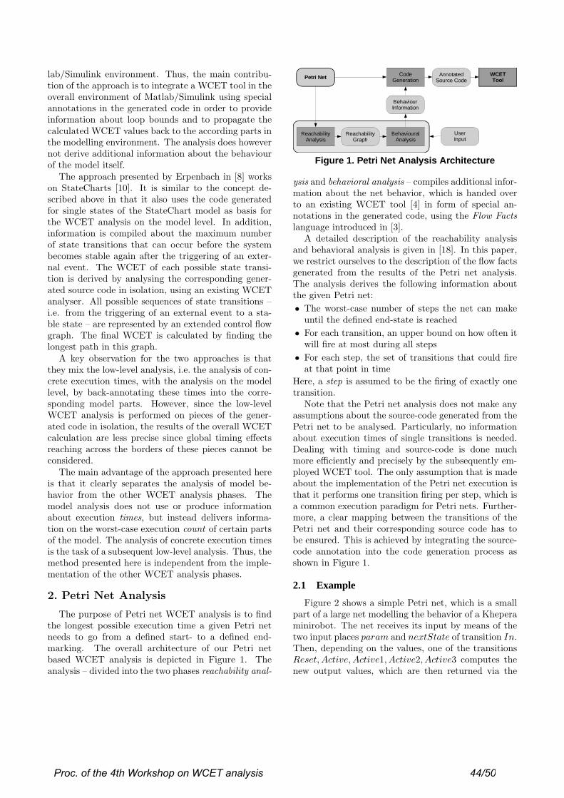
lab/Simulink environment. Thus, the main contribu-tion of the approach is to integrate a WCET tool in theoverall environment of Matlab/Simulink using specialannotations in the generated code in order to provideinformation about loop bounds and to propagate thecalculated WCET values back to the according parts inthe modelling environment. The analysis does howevernot derive additional information about the behaviourof the model itself.
The approach presented by Erpenbach in [8] workson StateCharts [10]. It is similar to the concept de-scribed above in that it also uses the code generatedfor single states of the StateChart model as basis forthe WCET analysis on the model level. In addition,information is compiled about the maximum numberof state transitions that can occur before the systembecomes stable again after the triggering of an exter-nal event. The WCET of each possible state transi-tion is derived by analysing the corresponding gener-ated source code in isolation, using an existing WCETanalyser. All possible sequences of state transitions –i.e. from the triggering of an external event to a sta-ble state – are represented by an extended control flowgraph. The final WCET is calculated by finding thelongest path in this graph.
A key observation for the two approaches is thatthey mix the low-level analysis, i.e. the analysis of con-crete execution times, with the analysis on the modellevel, by back-annotating these times into the corre-sponding model parts. However, since the low-levelWCET analysis is performed on pieces of the gener-ated code in isolation, the results of the overall WCETcalculation are less precise since global timing effectsreaching across the borders of these pieces cannot beconsidered.
The main advantage of the approach presented hereis that it clearly separates the analysis of model be-havior from the other WCET analysis phases. Themodel analysis does not use or produce informationabout execution times, but instead delivers informa-tion on the worst-case execution count of certain partsof the model. The analysis of concrete execution timesis the task of a subsequent low-level analysis. Thus, themethod presented here is independent from the imple-mentation of the other WCET analysis phases.
2. Petri Net Analysis
The purpose of Petri net WCET analysis is to findthe longest possible execution time a given Petri netneeds to go from a defined start- to a defined end-marking. The overall architecture of our Petri netbased WCET analysis is depicted in Figure 1. Theanalysis – divided into the two phases reachability anal-
AnnotatedSource Code
Petri Net
ReachabilityGraph
BehaviourInformation
ReachabilityAnalysis
BehaviouralAnalysis
CodeGeneration
WCETTool
UserInput
Figure 1. Petri Net Analysis Architecture
ysis and behavioral analysis – compiles additional infor-mation about the net behavior, which is handed overto an existing WCET tool [4] in form of special an-notations in the generated code, using the Flow Factslanguage introduced in [3].
A detailed description of the reachability analysisand behavioral analysis is given in [18]. In this paper,we restrict ourselves to the description of the flow factsgenerated from the results of the Petri net analysis.The analysis derives the following information aboutthe given Petri net:
• The worst-case number of steps the net can makeuntil the defined end-state is reached
• For each transition, an upper bound on how often itwill fire at most during all steps
• For each step, the set of transitions that could fireat that point in time
Here, a step is assumed to be the firing of exactly onetransition.
Note that the Petri net analysis does not make anyassumptions about the source-code generated from thePetri net to be analysed. Particularly, no informationabout execution times of single transitions is needed.Dealing with timing and source-code is done muchmore efficiently and precisely by the subsequently em-ployed WCET tool. The only assumption that is madeabout the implementation of the Petri net execution isthat it performs one transition firing per step, which isa common execution paradigm for Petri nets. Further-more, a clear mapping between the transitions of thePetri net and their corresponding source code has tobe ensured. This is achieved by integrating the source-code annotation into the code generation process asshown in Figure 1.
2.1 Example
Figure 2 shows a simple Petri net, which is a smallpart of a large net modelling the behavior of a Kheperaminirobot. The net receives its input by means of thetwo input places param and nextState of transition In.Then, depending on the values, one of the transitionsReset, Active,Active1, Active2, Active3 computes thenew output values, which are then returned via the
Proc. of the 4th Workshop on WCET analysis 44/50
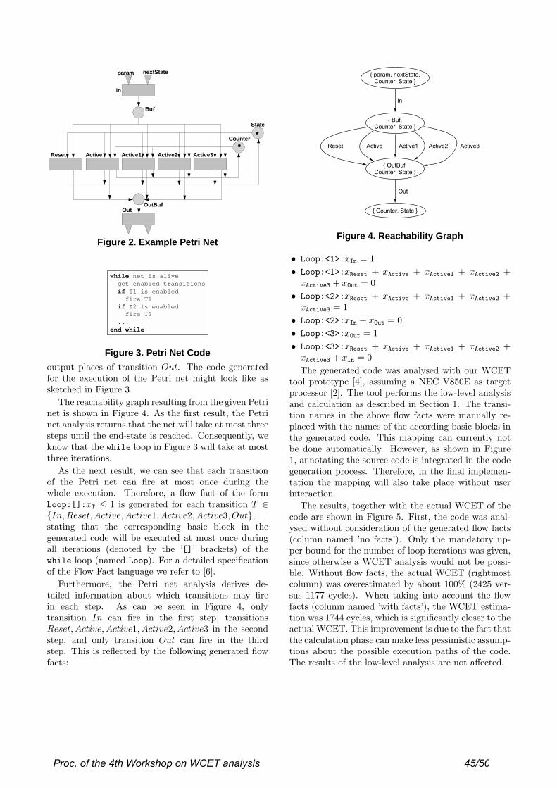
In
param
Reset Active Active2Active1 Active3
OutOutBuf
State
Counter
nextState
Buf
Figure 2. Example Petri Net
while net is alive get enabled transitions if T1 is enabled fire T1 if T2 is enabled fire T2 ...end while
Figure 3. Petri Net Code
output places of transition Out. The code generatedfor the execution of the Petri net might look like assketched in Figure 3.
The reachability graph resulting from the given Petrinet is shown in Figure 4. As the first result, the Petrinet analysis returns that the net will take at most threesteps until the end-state is reached. Consequently, weknow that the while loop in Figure 3 will take at mostthree iterations.
As the next result, we can see that each transitionof the Petri net can fire at most once during thewhole execution. Therefore, a flow fact of the formLoop:[]:xT ≤ 1 is generated for each transition T ∈{In,Reset, Active,Active1, Active2, Active3, Out},stating that the corresponding basic block in thegenerated code will be executed at most once duringall iterations (denoted by the ’[]’ brackets) of thewhile loop (named Loop). For a detailed specificationof the Flow Fact language we refer to [6].
Furthermore, the Petri net analysis derives de-tailed information about which transitions may firein each step. As can be seen in Figure 4, onlytransition In can fire in the first step, transitionsReset, Active,Active1, Active2, Active3 in the secondstep, and only transition Out can fire in the thirdstep. This is reflected by the following generated flowfacts:
Figure 4. Reachability Graph
• Loop:<1>:xIn = 1
• Loop:<1>:xReset + xActive + xActive1 + xActive2 +xActive3 + xOut = 0
• Loop:<2>:xReset + xActive + xActive1 + xActive2 +xActive3 = 1
• Loop:<2>:xIn + xOut = 0
• Loop:<3>:xOut = 1
• Loop:<3>:xReset + xActive + xActive1 + xActive2 +xActive3 + xIn = 0
The generated code was analysed with our WCETtool prototype [4], assuming a NEC V850E as targetprocessor [2]. The tool performs the low-level analysisand calculation as described in Section 1. The transi-tion names in the above flow facts were manually re-placed with the names of the according basic blocks inthe generated code. This mapping can currently notbe done automatically. However, as shown in Figure1, annotating the source code is integrated in the codegeneration process. Therefore, in the final implemen-tation the mapping will also take place without userinteraction.
The results, together with the actual WCET of thecode are shown in Figure 5. First, the code was anal-ysed without consideration of the generated flow facts(column named ’no facts’). Only the mandatory up-per bound for the number of loop iterations was given,since otherwise a WCET analysis would not be possi-ble. Without flow facts, the actual WCET (rightmostcolumn) was overestimated by about 100% (2425 ver-sus 1177 cycles). When taking into account the flowfacts (column named ’with facts’), the WCET estima-tion was 1744 cycles, which is significantly closer to theactual WCET. This improvement is due to the fact thatthe calculation phase can make less pessimistic assump-tions about the possible execution paths of the code.The results of the low-level analysis are not affected.
Proc. of the 4th Workshop on WCET analysis 45/50

Figure 5. Analysis Results3. Conclusion
In this paper, a WCET analysis for Petri nets waspresented. Independently of the source-code generatedfor a given Petri net, the analysis compiles informationabout the behavior of the net. The gathered infor-mation is then converted to a set of flow facts, whichare exploited by a subsequently employed source-codebased WCET tool. Using this additional information,a more precise WCET estimation is achieved than byjust analysing the generated source code alone. Infor-mation from the model (i.e. Petri net) level is thereforenot lost on the next lower level of the generated source-code.
From the example in Section 2.1, it can be seen thatthe flow facts derived by the Petri net analysis lead toa much tighter prediction of the WCET, even for therelatively simple net presented in the example.
A basic feature of the presented approach is thestrict separation from other WCET analysis phases,thereby consequently following our overall approach fora modular WCET tool architecture [4, 6]. This modu-lar approach makes it easy to e.g. replace an algorithmfor a certain analysis phase with a more efficient one.
Although the presented approach is based on Petrinets, the basic proposal of separating the model analy-sis from the other WCET analysis phases could also beapplied for other modelling paradigms, like e.g. State-Charts or Matlab/Simulink models.
References
[1] Peter Altenbernd, Lars O. Burchard, and Friedhelm Stap-pert. Worst-Case Execution Times Analysis of MPEG-2Decoding. In Proc. 6th International EUROMICRO Con-ference on Real-Time Systems, Stockholm, June 2000.
[2] NEC Corporation. V850E/MS1 32/16-bit Single Chip Mi-crocontroller: Architecture, 3rd edition, January 1999. Doc-ument no. U12197EJ3V0UM00.
[3] J. Engblom and A. Ermedahl. Modeling Complex Flowsfor Worst-Case Execution Time Analysis. In Proc. 21th
IEEE Real-Time Systems Symposium (RTSS’00), Novem-ber 2000.
[4] Jakob Engblom, Andreas Ermedahl, and Friedhelm Stap-pert. A Worst-Case Execution-Time Analysis Tool Proto-type for Embedded Real-Time Systems. In Paul Petterssonand Sergio Yovine, editors, Workshop on Real-Time Tools,Aalborg, Denmark, August 2001. Published as TechnicalReport No. 2001-014, Department of Information Technol-ogy, Uppsala University, Uppsala, Sweden.
[5] A. Ermedahl and J. Gustafsson. Deriving Annotations forTight Calculation of Execution Time. In Proc. Euro-Par’97Parallel Processing, LNCS 1300, pages 1298–1307. SpringerVerlag, August 1997.
[6] Andreas Ermedahl. A Modular Tool Architecture forWorst-Case Execution Time Analysis. PhD thesis, Upp-sala University, Dept. of Information Technology, Sweden,June 2003.
[7] E. Erpenbach, F. Stappert, and J. Stroop. Compilationand Timing Analysis of Statecharts Models for Embed-ded Systems. In The Second International Workshop onCompiler and Architecture Support for Embedded Systems(CASES’99), Washington, D.C, Oct. 1999.
[8] Edwin Erpenbach. Compilation, Worst-Case ExecutionTimes and Schedulability Analysis of Statecharts Models.PhD thesis, University of Paderborn, Germany, 2000.
[9] C. Ferdinand, F. Martin, and R. Wilhelm. Applying Com-piler Techniques to Cache Behavior Prediction. In Proc.ACM SIGPLAN Workshop on Languages, Compilers andTools for Real-Time Systems (LCT-RTS’97), 1997.
[10] D. Harel. Statecharts: A visual formalism for complex sys-tems. Science of Computer Programming, 8(3):231–274,June 1978.
[11] C. Healy, R. Arnold, F. Muller, D. Whalley, and M. Har-mon. Bounding Pipeline and Instruction Cache Perfor-mance. IEEE Transactions on Computers, 48(1), January1999.
[12] N. Holsti, T. Langbacka, and S. Saarinen. Worst-CaseExecution-Time Analysis for Digital Signal Processors. InProceedings of the EUSIPCO 2000 Conference (X EuropeanSignal Processing Conference), September 2000.
[13] Raimund Kirner. The programming language wcetc. Tech-nical Report 2/2002, Technische Universitt Wien, Institutfr Technische Informatik, 2002.
[14] Raimund Kirner, Roland Lang, Gerald Freiberger, and Pe-ter Puschner. Fully Automatic Worst-Case Execution TimeAnalysis for Matlab/Simulink Models. In EUROMICROConference on Real-Time Systems, 2002.
[15] Raimund Kirner and Peter Puschner. Transformation ofPath Information for WCET Analysis during Compilation.In Proc. 13th Euromicro Conference of Real-Time Systems,(ECRTS’01), June 2001.
[16] C. Y. Park. Predicting Program Execution Times by Ana-lyzing Static and Dynamic Program Paths. Real-Time Sys-tems, 5(1):31–62, March 1993.
[17] F. Stappert and P. Altenbernd. Complete Worst-Case Exe-cution Time Analysis of Straight-line Hard Real-Time Pro-grams. Journal of Systems Architecture, 46(4):339–355,2000.
[18] Friedhelm Stappert. From Low-Level to Model-Based andConstructive Worst-Case Execution Time Analysis. PhDthesis, Faculty of Computer Science, Electrical Engineering,and Mathematics, University of Paderborn, 2004. C-LABPublication, Vol. 17, Shaker Verlag, ISBN 3-8322-2637-0.
Proc. of the 4th Workshop on WCET analysis 46/50

Measurement-Based Worst-Case Execution Time Analysis usingAutomatic Test-Data Generation ∗
Raimund Kirner, Peter Puschner, Ingomar WenzelInstitut fur Technische Informatik
Technische Universitat WienTreitlstraße 3/182/1
A-1040 Wien, Austria{raimund,peter,ingo}@vmars.tuwien.ac.at
Abstract
Traditional worst-case execution time (WCET)analysis methods based on static program analysis re-quire a precise timing model of a target processor. Theconstruction of such a timing model is expensive andtime consuming.
In this paper we present a hybrid WCET analy-sis framework using runtime measurements togetherwith static program analysis. The novel aspect ofthis framework is that it uses automatic generation oftest data to derive the instruction timing of code se-quences. Program paths are decomposed into subpathsto make execution-time analysis based on runtime mea-surements feasible.
1 Introduction
The current situation on WCET analysis is not sat-isfying, because widely used industrial-strength WCETanalysis tools are still missing [7].
One challenge of WCET analysis is the variable in-struction timing of processors. Complex processorshave performance increasing features like caches orpipelines that maintain an internal state that dependson the execution history. Precisely modeling these fea-tures is problematic as on the one side it becomes quitecomplex and on the other side, exact information ofthe previous instruction stream cannot be calculatedin general. A further problem is that the vendor’s doc-umentation of a processor’s instruction timing is often
∗This work has been supported by the FIT-IT researchproject “Model-Based Development of distributed EmbeddedControl Systems (MoDECS-d)”.
a very rough approximation of reality. Problems aris-ing on WCET analysis using static hardware modelingare described in [5].
A further problem of static WCET analysis is thatit is very time consuming to model features of com-plex processors and furthermore, it has to be done foreach processor for which WCET analysis is required.The alternative is to use measurement-based WCETanalysis. However, simply performing exhaustive end-to-end measurements is not feasible for real-size pro-grams. Therefore, measurement-based WCET analysisis used in combination with static analysis techniques.Approaches to hybrid WCET analysis do already ex-ist [4, 1] but research in this area is just at the be-ginning. The path analysis problem of static WCETanalysis is currently shifted to the problem of generat-ing test data for measurement-based approaches. Thecurrent approaches require the user to provide test dataor simply use random testing. In addition to runtimemeasurements, Ernst and Ye propose to switch backto traditional static WCET analysis techniques in casethat the test data provided by the user did not coverall program blocks [4].
In this paper we present a measurement-basedWCET analysis framework with automatic generationof test data. The problem of automatically generatingthe test data is tackled by standard program analysistechniques like model checking [2, 9] or constraint-basedanalysis [10]. The approach is based on decompositionof program paths into subpaths of program segments.A static WCET calculation method is used after the in-struction timing of subpaths of program segments hasbeen assessed by runtime measurements.
The paper is structured as follows: Section 2 gives adiscussion about demands from industry for the use ofWCET analysis tools. The measurement-based WCET
Proc. of the 4th Workshop on WCET analysis 47/50

analysis framework is described in Section 3. Section 4discusses technical aspects of the framework. Finally,Section 5 concludes this paper.
2 Requirements for an Industrial-Strength WCET Analysis Tool
Before describing our new WCET analysis method,we give a motivation for its development by describingthe industrial needs on a WCET analysis method. Pre-viously proposed WCET analysis methods often onlydemonstrate several analysis capabilities without show-ing their applicability in an industrial environment. Tobe more precise, the following list gives demands for aWCET analysis tool raised by people working in indus-try. This list also contains aspects regarding the useof modeling tools like Matlab/Simulink, as they areincreasingly used in industrial software development.
1. The tool must work with minimal user interac-tion. In particular, it cannot be expected thatusers of the tool provide manual code annotationsabout possible and impossible execution paths ofthe code. For example, when using a modelingtool like Matlab/Simulink, the WCET analysistool must be able to extract this information byanalyzing the code generated by the code genera-tor of Matlab/Simulink.
2. The method must integrate into the developmenttool chain of customers without modification oftools from the tool chain (e.g., components ofMatlab/Simulink, code generator, C compiler).
However, it may be possible to use the tool chainin a restrictive manner to enable the application ofa certain WCET analysis method. For example,the available application development features ofa modeling tool like Matlab/Simulink may be re-stricted or certain compiler optimizations may bedeactivated.
3. The method must be easily adaptable to new re-leases of software components of the tool chain.Expensive adaptations of the WCET method tonew releases of software components have to beavoided.
The situation that a development tool of the toolchain explicitly supports a specific WCET analysismethods is currently very rare. For example, itcan be possible that a compiler provides certainsupport to perform WCET analysis [6]. But suchtools are typically in a prototype state withoutcommercial support. Therefore, the best current
strategy for developing a WCET analysis tool isto adapt to existing COTS software developmenttools.
4. The WCET analysis method must be easy toretarget to different hardware settings, i.e., theimplementation or configuration effort must besmall enough for an economic useability of theWCET analysis method. Depending on the con-crete WCET analysis method, there are in prin-ciple two different possibilities for retargetability.First, it can be required to order further imple-mentation effort from the WCET tool provider.Second, it may be possible that the tool is flex-ible enough so that the customer can adapt thetool by himself. The latter approach is applicablefor adequate measurement-based WCET analysismethods.
The adaption of a WCET analysis method to newhardware configurations can be kept easy when theWCET analysis method is based on measurements onthe real hardware. Because in this case the WCETanalysis method does not have to provide a so-calledexec-time model, which describes the execution timesfor given code sequences. In measurement-based ap-proaches the exec-time model is substituted by mea-surements on the real target hardware. There exist alsomeasurement-based WCET analysis approaches thatuse hardware simulation instead of measurements onthe real hardware [3, 4]. Such approaches rely on theexistence of a cycle-accurate hardware simulator whichis often not available.
In the following section a new WCET analysismethod is presented that is able to fulfill the require-ments from industry as given above. This WCET anal-ysis method will be applied to program code automat-ically generated from Matlab/Simulink models be-cause there is additional information available aboutthe structure of the generated code.
3 The WCET Analysis Framework
A new WCET analysis approach is needed to ful-fill the requirements from industry listed in Section 2.Traditional methods based only on static code analysisare not flexible enough to retarget them with reason-able effort to new target processors. Though often usedin practice, end-to-end runtime measurements are notan alternative, due to the exploding number of possibleexecution paths in real-size programs.
The WCET analysis method we describe in this pa-per is a hybrid approach of static and dynamic analy-sis methods. The dynamic part is performed by run-
Proc. of the 4th Workshop on WCET analysis 48/50
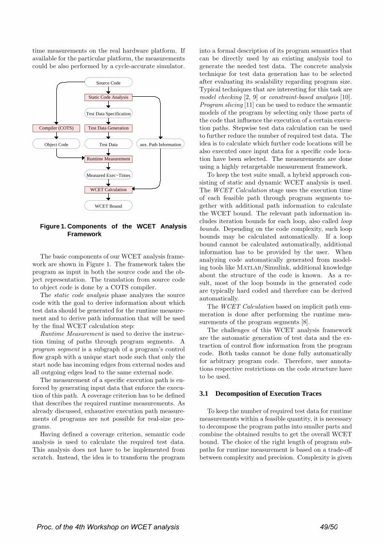
time measurements on the real hardware platform. Ifavailable for the particular platform, the measurementscould be also performed by a cycle-accurate simulator.
Test Data
Runtime Measurement
Measured Exec−Times
WCET Calculation
Test Data Generation
aux. Path Information
WCET Bound
Test Data Specification
Source Code
Object Code
Compiler (COTS)
Static Code Analysis
Figure 1. Components of the WCET AnalysisFramework
The basic components of our WCET analysis frame-work are shown in Figure 1. The framework takes theprogram as input in both the source code and the ob-ject representation. The translation from source codeto object code is done by a COTS compiler.
The static code analysis phase analyzes the sourcecode with the goal to derive information about whichtest data should be generated for the runtime measure-ment and to derive path information that will be usedby the final WCET calculation step:
Runtime Measurement is used to derive the instruc-tion timing of paths through program segments. Aprogram segment is a subgraph of a program’s controlflow graph with a unique start node such that only thestart node has incoming edges from external nodes andall outgoing edges lead to the same external node.
The measurement of a specific execution path is en-forced by generating input data that enforce the execu-tion of this path. A coverage criterion has to be definedthat describes the required runtime measurements. Asalready discussed, exhaustive execution path measure-ments of programs are not possible for real-size pro-grams.
Having defined a coverage criterion, semantic codeanalysis is used to calculate the required test data.This analysis does not have to be implemented fromscratch. Instead, the idea is to transform the program
into a formal description of its program semantics thatcan be directly used by an existing analysis tool togenerate the needed test data. The concrete analysistechnique for test data generation has to be selectedafter evaluating its scalability regarding program size.Typical techniques that are interesting for this task aremodel checking [2, 9] or constraint-based analysis [10].Program slicing [11] can be used to reduce the semanticmodels of the program by selecting only those parts ofthe code that influence the execution of a certain execu-tion paths. Stepwise test data calculation can be usedto further reduce the number of required test data. Theidea is to calculate which further code locations will bealso executed once input data for a specific code loca-tion have been selected. The measurements are doneusing a highly retargetable measurement framework.
To keep the test suite small, a hybrid approach con-sisting of static and dynamic WCET analysis is used.The WCET Calculation stage uses the execution timeof each feasible path through program segments to-gether with additional path information to calculatethe WCET bound. The relevant path information in-cludes iteration bounds for each loop, also called loopbounds. Depending on the code complexity, such loopbounds may be calculated automatically. If a loopbound cannot be calculated automatically, additionalinformation has to be provided by the user. Whenanalyzing code automatically generated from model-ing tools like Matlab/Simulink, additional knowledgeabout the structure of the code is known. As a re-sult, most of the loop bounds in the generated codeare typically hard coded and therefore can be derivedautomatically.
The WCET Calculation based on implicit path enu-meration is done after performing the runtime mea-surements of the program segments [8].
The challenges of this WCET analysis frameworkare the automatic generation of test data and the ex-traction of control flow information from the programcode. Both tasks cannot be done fully automaticallyfor arbitrary program code. Therefore, user annota-tions respective restrictions on the code structure haveto be used.
3.1 Decomposition of Execution Traces
To keep the number of required test data for runtimemeasurements within a feasible quantity, it is necessaryto decompose the program paths into smaller parts andcombine the obtained results to get the overall WCETbound. The choice of the right length of program sub-paths for runtime measurement is based on a trade-offbetween complexity and precision. Complexity is given
Proc. of the 4th Workshop on WCET analysis 49/50

by the number of required runtime measurements. Incase of complex processors having an internal state thatinfluences the execution time of instructions, measure-ment precision is better when measuring longer sub-paths of the program.
One important aspect for the decomposition of exe-cution traces is the demanded coverage criteria for themeasurements. The coverage criteria will be defined atthe level of program segments. For using this frame-work to obtain safe WCET bounds on a given hard-ware platform it has to analyzed what is the possibleoverestimation for particular coverage criteria.
4 Discussion
The design criteria of the measurement-basedWCET analysis framework described in Section 3are motivated by the requirements for an industrial-strength WCET analysis tool as summarized in Sec-tion 2. The decision of performing the program anal-ysis at source code level is due to the requirement ofhigh retargetability of the framework to new hardwareplatforms. However, for certain application domainsit may be more important to have the analysis doneafter the code compilation at object code level. Forexample, it could be required to verify the path cov-erage calculated for source code level at object codelevel in case of critical code optimizations done by thecompiler. In this case, the concept of the measurement-based WCET analysis using on automatic generationof test data is the same, but the implementation wouldbe more hardware-dependent as it is also required tohave a parser for the object code.
Technical realizations like inserting instrumentationcode to measure the execution time of program seg-ments are not discussed in this paper.
5 Summary and Conclusion
This paper describes a novel WCET analysis frame-work based on runtime measurements. The require-ments for the framework are high portability to newtarget processors and an easy integration into COTSsoftware development tool chains. We described a hy-brid approach using static and dynamic timing analysistechniques. The central idea is to decompose the pro-gram paths into smaller subpaths and use formal meth-ods to automatically derive the required test data tomeasure the execution time of the subpaths. Programsare structured into program segments to decomposeprogram paths into smaller subpaths. After measuringthe execution time of subpaths, a static WCET calcu-lation is used to obtain the WCET bound.
Future work will focus on the assessment and selec-tion of concrete formal program analysis techniques togenerate the test data.
References
[1] G. Bernat, A. Colin, and S. M. Petters. WCET anal-ysis of probabilistic hard real-time systems. In Proc.23rd Real-Time Systems Symposium, pages 279–288,Austin, Texas, USA, Dec. 2002.
[2] A. Chlipala, T. Henzinger, R. Jhala, and R. Majum-dar. Generating tests from counterexamples. In Pro-ceedings of the International Conference on SoftwareEngineering, Edinburgh, Scotland, UK, 2004.
[3] J. Engblom and A. Ermedahl. Pipeline timing analysisusing a trace-driven simulator. In Proc. 6th Interna-tional Conference on Real-Time Computing Systemsand Applications, Hong Kong, Dec. 1999.
[4] R. Ernst and W. Ye. Embedded program timing analy-sis based on path clustering and architecture classifica-tion. In Proc. International Conference on Computer-Aided Design (ICCAD ’97), San Jose, USA, 1997.
[5] R. Heckmann, M. Langenbach, S. Thesing, andR. Wilhelm. The influence of processor architectureon the design and results of wcet tools. Proceedings ofthe IEEE, 91(7):1038–1054, Jul. 2003.
[6] R. Kirner and P. Puschner. Timing analysis of opti-mised code. In Proc. 8th IEEE International Work-shop on Object-oriented Real-time Dependable Systems(WORDS 2003), pages 100–105, Guadalajara, Mex-ico, Jan. 2003.
[7] P. Puschner. Is worst-case execution-time analysisa non-problem? – towards new software and hard-ware architectures. In Proc. 2nd Euromicro Interna-tional Workshop on WCET Analysis, Technical Re-port, York YO10 5DD, United Kingdom, June 2002.Department of Computer Science, University of York.
[8] P. Puschner and A. V. Schedl. Computing MaximumTask Execution Times – A Graph-Based Approach.The Journal of Real-Time Systems, 13:67–91, 1997.
[9] S. Rayadurgam and M. P. E. Heimdahl. Coveragebased test-case generation using model checkers. InProc. 8th IEEE International Conference and Work-shop on the Engineering of Computer Based Systems(ECBS ’01), Washington DC, USA, Apr. 2001.
[10] N. T. Sy and Y. Deville. Consistency techniques forinterprocedural test data generation. In Proc. Joint9th European Software Engineering Conference and11th ACM SIGSOFT Symposium on the Foundation ofSoftware Engineering (ESEC/FSE03), Helsinki, Fin-land, 2003.
[11] F. Tip. A survey of program slicing techniques. Jour-nal of Programming Languages, 3(3):121–189, 1995.
Proc. of the 4th Workshop on WCET analysis 50/50


![PaRTAA: A Real-time Multiprocessor for Mixed-Criticality Airborne … · including determination of worst case execution time (WCET) [8]. The concept of interconnecting multiple partitioned](https://img.pdfslide.us/doc/110x75/61314e961ecc51586944a738/partaa-a-real-time-multiprocessor-for-mixed-criticality-airborne-including-determination.jpg)