Embed Size (px)
Citation preview
Your Source for Success
4th Annual
CONFERENCE & EXHIBITION
November 17-20, 1998Hotel Vancouver
Vancouver, British Columbia
Randol International Ltd.21578 Mountsfield Drive
Golden, Colorado 80401 USAPhone: (303) 526-1626; Fax (303) 526-1650
Web site: www.randol.comE-mail: [email protected]
1
SOLVENT EXTRACTION DILUENTSWHAT ARE THEY AND How DO THEY
AFFECT SX PLANT COSTS?
M.D. BishopPhillips Mining Chemicals
1768 Highway 123Bartlesville, OK 74004
Phone: (918) 661-9380; Fax: (918) 662-5201E-mail: [email protected]
The regulation was designed to decrease ground level ozoneand is based on studies, which have shown that hydrocarbonvapors can contribute to the fonnation of ground level ozone.The compounds, which are excluded by legislation, have beenstudied and detennined to not conb'ibute to ozone fonnation.High molecular weight hydrocarbons are generally considered tohave minimal impact due to their low volatility.
The California Air Resources Board (CARB) recognizes thelow impact of higher molecular weight hydrocarbons. CARBdefines hydrocarbons of greater than C'2 or with vapor pressuresless than 0.1 mm of Hg at 200 C as LVP-VOC (Low VaporPressure - VOC) substances. The LVP-VOC designationincludes those chemical compounds and the weight percent of amixture with a boiling point greater than 2160 C (4210 F).'These compounds are excluded from some regulatory require-ments when used in consumer goods. However, there are noexemptions for industrial point sources.
There are two general b'ends in distillate physical propertiesthat help define the boundaries for practical diluents.Although these b'ends are well known, it is important to reviewthem in consideration of solvent extraction operations.Consideration of these factors generally limits commercial dilu-ents to those compounds with carbon numbers primarilybetween CIO and C2o.
. The vapor pressure of the hydrocarbon decreases as themolecular weight (carbon number) increases.
. The viscosity of the hydrocarbon increases as the molecu-lar weight increases.
The vapor pressure of a hydrocarbon is related to its volatili-ty. Lower molecular weight hydrocarbons have higher vaporpressure. This leads to increased volatilit).; i.e. they evaporatemore rapidly. The vapor pressure of typical diluents is in therange of I to 3 mm Hg at 380 C. Since vapor pressure is relatedto flash point, lower molecular weight hydrocarbons will have alower flash point. However flash point is, as discussed later, notdefinitive.
ABSTRACTSolvent extraction diluent and extractant are blended in the
appropriate ratios as determined by the plant operational require-ments. The resultant solution is the plant organic. The diluent isnormally the majority fraction of the plant organic and, as such,plays an essential roll in efficient operation of the solvent extrac-tion circuit. This paper discusses some of the terms associatedwith diluents, their characteristics, and considerations for mini-mizing operating costs.
Modem solvent extraction diluents are constant compositionpetroleum distillates that have been developed specifically foruse in solvent extraction circuits. They contain a range of hydro-carbons composed of aliphatic, aromatic, and naphthenic com-pounds. The terms are used in the petroleum industry to denotethe structure of the chemical compound. Aliphatic compoundsare open chain molecular structures; alkanes, alkenes, andalkynes, including both normal (linear) and iso (branched)species and their cyclic analogs'. Aromatics are those com-pounds that contain one or more unsaturated ring structures)somewhere in the molecule. Although this term includes classi-cal aromatics such as benzene and toluene, these compounds arenot present in any appreciable concentration in modem diluents.The aromatics in modem diluents are heavier compounds moreaccurately called alkylaromatics or arenes. The distinguishingfeature of these aromatics is an unsaturated ring structure withone or more aliphatic chains attached to the ring. Cycloalkanesare known as naphthenes in the petroleum industry. This termshould not be confused with naphthalene (camphor). The origi-nal meanings of the term "aliphatic" (fatty) and "aromatic" (fra-grant) are no longer significant.'
All diluents in current commercial use are volatile organiccompounds (VOCs) as defined by regulation. US regulationsdefine a VOC as any compound of carbon and hydrogen unlessexcluded by legislation. For example, methane (CH4) is com-pose of only carbon and hydrogen but is not a VOC. It is exclud-ed by legislation.
121 COPPER HVDROMET ROUNDTABLE '98
,"~.:Q:..~!~.~.9~
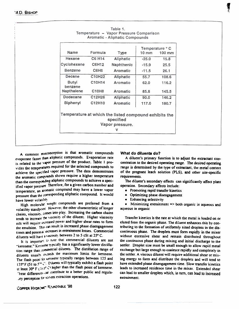
A common mIsconception is that aromatic compoundsevaporate faster than aliphatic compounds. Evaporation rateis related to th( vaJ"'f pressure of the product. Table I pro-vides the tempcrawrts ~uired for the selected compounds toachieve the spC"-'itW vapor pressure. The data demonstratesthe aromatic c(\It\I"\Unds shown require a higher temperaturethan the corresl"lftJing aliphatic compounds to achieve a spec-ified vapor prtSSUf(' The~fore, for a given carbon number andtemperature, an at\'n1stic compound may have a lower vaporpressure than th( ",~Sr<'nding aliphatic compound. It would
have lower volatill~High molecu1a.- "~i~ht compounds are preferred from a
volatility standf'~": H..'I~'ever. the other characteristic of longerchains, viscosi~, "'~ anto play. Increasing the carbon chainstends to increa.~ ~ \ ~cosi~' of the diluent. Higher viscosityoils will requirt' ..").~.L~ po~'er. and higher shear rates to fonnthe emulsion. Th~ ,SrI result an increased phase disengagementtimes and potentoS t)..'rt'ase5 in entrainment losses. Commercialdiluents will ha\-: 1 \~,,'Si~ between 2 to 5 cSt at 250 C.
It is impon~~ -;.' nNe that commercial diluents are not.'kerosene." Kt:~.~ ~J'I,3\1~ has a significantly lower distilla-tion range than ",~i,tl diluents. The distillatiOn range ofdiluents usual" :".'«Ii- the maximum limits for kerosene.The flash poin: ~'\' ..t':\'S~e ~~ically. ranges between 125 and1350 F (51 to 5- ,,~'. [\:l~ts "'111 typIcally exhibit a flash point'It least 300 F t ::-.:-" ...~\ higher than the flash point of kerosene.~hcse diffcrc~~ ,r- ,,"~uibute to a better public and regula-
Jry perception ~'\. ~,'\-:nt ~xD'action operations.
What do dlluents do?A diluent's primary function is to adjust the extractant con-
centration to the desired operating range. The desired operatingrange is determined by the type of extractant, the metal contentof the pregnant leach solution (PLS), and other site-specificrequirements.
The diluent's secondary effects can significantly affect plantoperation. Secondary affects include:
. Promoting rapid transfer kinetics
. Optimizing phase disengagement
. Enhancing selectivity
. Minimizing entrainment -> both organic in aqueous andaqueous in organic
Transfer kinetics is the rate at which the metal is loaded on oreluted from the organic phase. The diluent enhances this by con-tributing to the formation of uniformly sized droplets in the dis-continuous phase. The droplets must form rapidly in the mixerwithout excessive shear and remain distributed throughoutthe continuous phase during mixing and initial discharge to thesenler. Droplet size must be small enough to allow rapid metalexchange but large enough to coalesce rapidly and completely inthe senler. A viscous diluent will require additional shear or mix-ing energy to form and distribute the droplets and will tend tohave extended phase disengagement time. Slow transfer kineticsleads to increased residence time in the mixer. Extended shearcan lead to smaller droplets which, in turn, can lead to increasedentrainment.
COPPER HvQR::*- ~~~TA8lE '98 122
~~M.D. BtSHOP
Phase disengagement time is the time required for the aque-ous and organic phases to separate. Phase break time is easilymeasured in a laboratory batch cell and correlates to the disper-sion band in the plant. Large droplets coalesce faster but requirelonger times for metal transfer. Small droplets transfer metalsrapidly but may not coalesce rapidly or completely. Optimizedphase disengagement contributes to maximizing plant flow ratesand production.
A slow phase break can lead to reduced production. Thiswould be a result of decreased flow rates due to failure of thephases to disengage in the settler. Slow phase breaks can resultin increased entrainment and increase in the associated costs.
Conversely, a rapid phase break can contribute to increasedcopper production. This is provided additional PLS is availableand the tank house has the capacity. Extremely rapid phase dis-engagement is not always beneficial as metal transfer is occur-ring as the phases coalesce. This could result in reduced metaltransfer. In some cases, extremely fast phase breaks can trend topoor coalescence, potentially leading to higher entrainment.
Studies have demonstrated that the diluent composition willaffect copper iron selectivity in oxime based systems. Analkylaromatic content of 10 to 30 volume percent appears toenhance Cu: Fe selectivity. The optimum alkylaromatic con-tent appears to be in the 22 to 25% range.6 Reduced iron trans-fer will result in reduced electrolyte bleed stream volume andreduced cobalt consumption provided iron is the controllingfactor in bleed stream volume.
Entrainment is a measure of incomplete coalescing of the dis-continuous phase. Organic in aqueous entrainment in the loadingstage is one of the major sources of organic loss. Organic exit-ing the circuit in raffinate is normally recovered from the raffi-nate pond. Organic in the electrolyte is absorbed in the elec-trolyte filters. Aqueous entrainment contributes to transfer ofundesirable ions such a CI- through the circuit.
Each of these elements is also influenced by and interrelat-ed with the other plant variables including extractant type andconcentration, pH, mixer design, circuit temperature, and PLSquality.
immediately after the ignition source is withdrawn. The prim-ary difference between the methods is that the PMCC USES astirring mechanism while the TCC does not.
The COC method, as the name implies, does not incorpo-rate a cover over the sample. The vapors are free to the atmos-phere. The ignition source is periodically introduced into thevapor at a prescribed distance above the liquid. The sample isnot stirred. For diluents, the open cup flash point will typical-ly be 20 - 25° F (11 - 14° C) higher than the closed cup valuefor the same material.
The Setaflash method (ASTM D 3828) may be used as analternative to the TCC or PMCC methods. The Setaflash makesuse of a smaller sample and utilizes a timed interval in approach-ing the estimated flash point.
Flash point is not linear with composition and can not berelied on to predict overall volatility. Since the closed cup flashpoint apparatUS contains the vapors in the headspace and thelighter components are volatilized preferentially, the light com-ponents will have a disproportionate effect on the flash point.Blending a 1:1 mixture of a low flash material such as hexane (aC6 hydrocarbon) with a high flash point material such as hexa-decane (CI6) would not result in a flash point half way betweenthe two products. It would actually be very close to that of purehexane. A relative small amount of a light component canreduce the flash point by several degrees.
Barometric pressure has a significant effect on flash point.The lower the barometric pressure the lower the measured flashpoint. ASTM methods specify that the reported flash point becorrected for variations in barometric pressure. All values repon-ed are corrected to standard pressure (sea level), 760 mm Hg.Since barometric pressure decreases by approximately 2.5 mmHg for each 30.5 meters in increased elevation', we can predictthe flash point at various altitudes. The flash point at a givenaltitude can be estimated by decreasing the reported flash point(corrected to sea level) by 0.228° C per 100 meters elevationabove sea level. For example, an operation at 4,000 meterswould expect to observe a 9° C decrease in flash point (4,000 +100 x 0.228).
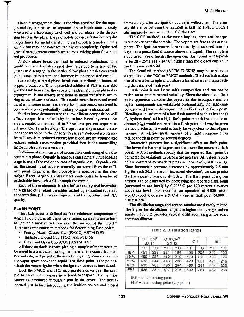
The distillation range and carbon number are directly related.The higher the distillation range, the higher the average carbonnumber. Table 2 provides typical distillation ranges for somecommon diluents.
FLASH POINTThe flash point is defined as "the minimum temperature at
which a liquid gives off vapor in sufficient concenb'ation to forman ignitable mixture with air near the surface of the liquid.'"There are three common methods for determining flash point:
. Pensky Martin Closed Cup [PMCC] ASTM D 93
. Tagliabeu Closed Cup [TCC] ASTM D 56
. Cleveland Open Cup [COC] ASTM D 92All three methods involve placing a sample of the material to
be tested in a brass cup, heating the material in a controtled man-ner and rate, and periodicatly introducing an ignition source intothe vapor space above the liquid. The flash point is the point atwhich the vapors ignite when the ignition source is introduced.
80th the PMCC and TCC incorporate a cover over the sam-ple to contain the vapors in a fixed heads pace. The ignitionsource is introduced through a pon in the cover. The port isopened just before introducing the ignition source and closed
123 COPPER HVDROMET ROUNDTABLE '98
.~.:.q:...~~.~.<?~.
There are many sources of diluent loss. They include but arenot limited to the following.
. Entrainment
. Evaporation
. Filter Loss
. Crud Loss
. Solubility. Carryover to Electrolyte
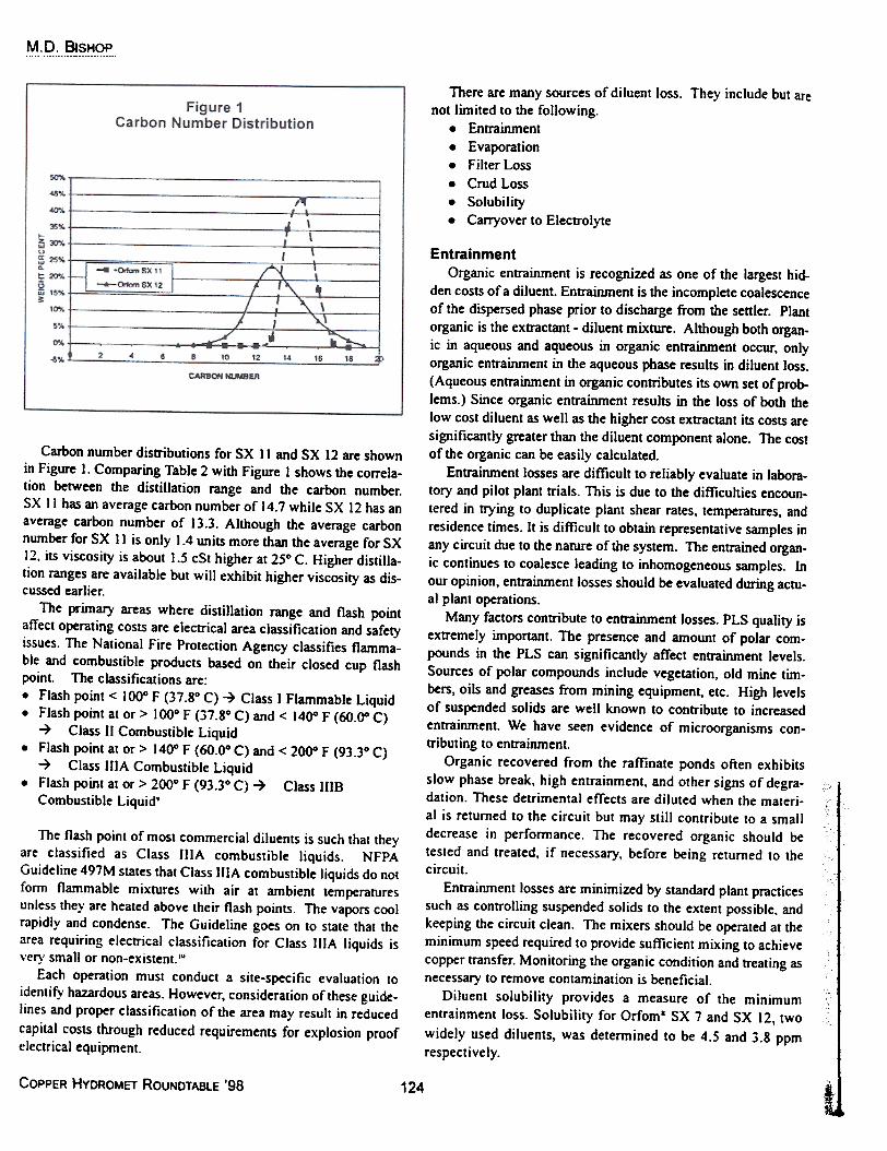
Carbon number disnibutions for SX II and SX 12 are shownin Figure I. Comparing Table 2 with Figure I shows the correla-tion between the distillation range and the carbon number.SX II has an average carbon number of 14.7 while SX 12 has anaverage carbon number of 13.3. Although the average carbonnumber for SX II is only 1.4 units more than the average for SX12. its viscosity is about 1.5 cSt higher at 25° C. Higher distilla-tion ranges are available but will exhibit higher viscosity as dis-cussed earlier.
The primary areas where distillation range and flash pointaffect operating costs are electrical area classification and safetyissues. The National Fire Protection Agency classifies flamma-ble and combustible products based on their closed cup flashpoint. The classifications are:. Flash point < 100° F (37.8° C) ~ Class I Flammable Liquid. Flash point at or> 100° F (37.8° C) and < 140° F (60.00 C)
~ Class II Combustible Liquid. Flash point at or> 140° F (60.0° C) and < 2000 F (93.3° C)~ Class IlIA Combustible Liquid
. Flash point at or > 200° F (93.3° C) ~ Class IIIBCombustible Liquid'
The flash point of most commercial diluents is such that theyare classified as Class IlIA combustible liquids. NFPAGuideline 497M states that Class IlIA combustible liquids do notform flammable mixtures with air at ambient temperaturesunless they are heated above their flash points. The vapors coolrapidly and condense. The Guideline goes on to state that thearea requiring electrical classification for Class IlIA liquids isvery small or non-existent.'"
Each operation must conduct a site-specific evaluation toidentify hazardous areas. However, consideration of these guide-lines and proper classification of the area may result in reducedcapital costs through reduced requirements for explosion proofelectrical equipment.
EntrainmentOrganic entrainment is recognized as one of the largest hid-
den costs of a diluent. Entrainment is the incomplete coalescenceof the dispersed phase prior to discharge from the settler. Plantorganic is the exttactant - diluent mixture. Although both organ-ic in aqueous and aqueous in organic enttainment occur, onlyorganic enttainment in the aqueous phase results in diluent loss.(Aqueous entrainment in organic contributes its own set ofprob-lems.) Since organic entrainment results in the loss of both thelow cost diluent as well as the higher cost exttactant its costs aresignificantly greater than the diluent component alone. The costof the organic can be easily calculated.
Enttainment losses are difficult to reliably evaluate in labora-tory and pilot plant trials. This is due to the difficulties encoun-tered in trying to duplicate plant shear rates, temperatures, andresidence times. It is difficult to obtain representative samples inany circuit due to the nature of the system. The entrained organ-ic continues to coalesce leading to inhomogeneous samples. Inour opinion, enttainment losses should be evaluated during actu-al plant operations.
Many factors contribute to enttainment losses. PLS quality isextremely important. The presence and amount of polar com-pounds in the PLS can significantly affect enttainment levels.Sources of polar compounds include vegetation, old mine tim-bers, oils and greases from mining equipment, etc. High levelsof suspended solids are well known to contribute to increasedentrainment. We have seen evidence of microorganisms con-tributing to entrainment.
Organic recovered from the raffinate ponds often exhibitsslow phase break, high entrainment, and other signs of degra-dation. These detrimental effects are diluted when the materi-al is returned to the circuit but may still contribute to a smalldecrease in performance. The recovered organic should betested and treated, if necessary, before being returned to thecircuit.
Entrainment losses are minimized by standard plant practicessuch as controlling suspended solids to the extent possible, andkeeping the circuit clean. The mixers should be operated at theminimum speed required to provide sufficient mixing to achievecopper transfer. Monitoring the organic condition and treating asnecessary to remove contamination is beneficial.
Diluent solubility provides a measure of the minimumentrainment loss. Solubility for Orfom& SX 7 and SX 12, twowidely used diluents, was determined to be 4.5 and 3.8 ppmrespectively.
COPPER HVDROMET ROUNDTABLE '98
~
124
M.D. BISHOP
-
EvaporationEvaporative losses are a concern to operations for both cost
and environmental reasons. Factors affecting evaporative lossinclude circuit temperature, altitude, and plant design. Highercircuit temperatures will tend to increase evaporative loss. Highaltitude operations are expected to have higher evaporative loss-es due to reduced barometric pressure. Plant design also affectsevaporative losses as covered mixer-settlers will have less airmovement over the organic surface than uncovered circuits.
It is well accepted that diluent is preferentially lost from plantorganic. The amount of diluent required to maintain the plantorganic's extractant: diluent ratio is greater than the amount ofdiluent required based on the quantity of extractant added formake-up. "Conventional wisdom" has contributed this differen-tialloss to evaporation. Logic suppons this concept. Since dilu-ents are lower molecular weight than extractants the diluentwould evaporate while the higher molecular weight extractantwould not evaporate.
Phillips Mining Chemicals has investigated evaporative lossin an effon to quantify the contribution of evaporation to diluentloss. We have adapted ASTM method D 972 Standard TestMethod for Evanoration l,oss ofLubricatin~ Greases;;;;dO:;l;. tomeasured diluent evaporative losses. We have also measuredevaporation from beakers.
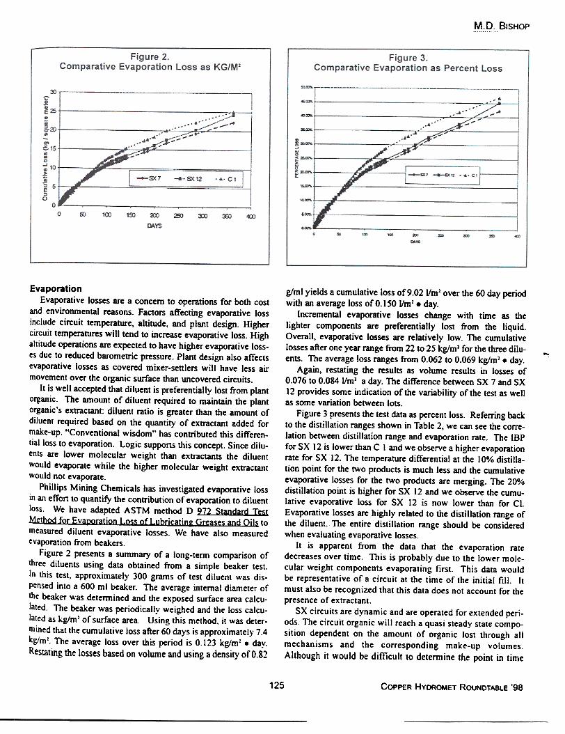
Figure 2 presents a summary of a long-term comparison ofthree diluents using data obtained from a simple beaker test.In this test, approximately 300 grams of test diluent was dis-pensed into a 600 ml beaker. The average internal diameter ofthe beaker was determined and the exposed surface area calcu-lated. The beaker was periodically weighed and the loss calcu-lated as kg/m: of surface area. Using this method. it was deter-mined that the cumulative loss after 60 days is approximately 7.4kg/m:. The average loss over this period is 0.123 kg/m2 . day.Restating the losses based on volume and using a density of 0.82
glml yields a cumulative loss of 9.02 Um1 over the 60 day periodwith an average loss of 0.150 Um1. day.
Incremental evaporative losses change with time as thelighter components are preferentially lost from the liquid.Overall, evaporative losses are relatively low. The cumulativelosses after one year range from 22 to 25 kglm1 for the three dilu-ents. The average loss ranges from 0.062 to 0.069 kg/m1 . day.
Again, restating the results as volume results in losses of0.076 to 0.084 Um1 a day. The difference between SX 7 and SX12 provides some indication of the variability of the test as wellas some variation between lots.
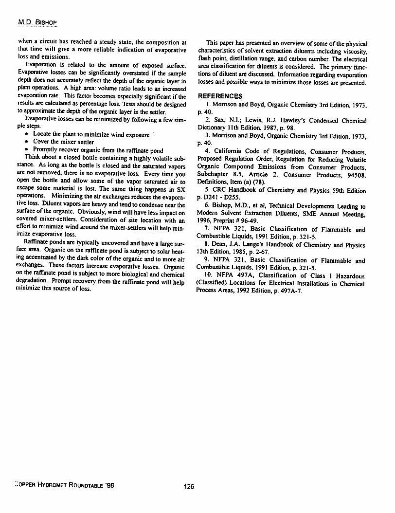
Figure 3 presents the test data as percent loss. Referring backto the distillation ranges shown in Table 2, we can see the corre-lation between distillation range and evaporation rate. The IBPfor SX 12 is lower than C I and we observe a higher evaporationrate for SX 12. The temperature differential at the 10% distilla-tion point for the two products is much less and the cumulativeevaporative losses for the two products are merging. The 200/0distillation point is higher for SX 12 and we observe the cumu-lative evaporative loss for SX 12 is now lower than for Cl.Evaporative losses are highly related to the distillation range ofthe diluent. The entire distillation range should be consideredwhen evaluating evaporative losses.
It is apparent from the data that the evaporation ratedecreases over time. This is probably due to the lower mole-cular weight components evaporating first. This data wouldbe representative of a circuit at the time of the initial fill. Itmust also be recognized that this data does not account for thepresence of extractant.
SX circuits are dynamic and are operated for extended peri-ods. The circuit organic will reach a quasi steady state compo-sition dependent on the amount of organic lost through allmechanisms and the corresponding make-up volumes.Although it would be difficult to detern1ine the point in time
125 COPPER HVDROMET ROUNDTABLE '98
M.D. BISHOP"""."",.",..,.".""",
This paper has presented an overview of some of the physicalcharacteristics of solvent extraction diluents including viscosity,flash point, distillation range, and carbon number. The electricalarea classification for diluents is considered. The primary func-tions of diluent are discussed. Information regarding evaporationlosses and possible ways to minimize those losses are presented.
REFERENCESI. Morrison and Boyd, Organic Chemistry 3rd Edition, 1973,
when a circuit has reached a steady state, the composition atthat time will give a more reliable indication of evaporativeloss and emissions.
Evaporation is related to the amount of exposed surface.Evaporative losses can be significantly overstated if the sampledepth does not accurately reflect the depth of the organic layer inplant operations. A high area: volwne ratio leads to an increasedevaporation rate. This factor becomes especially significant if theresults are calculated as percentage loss. Tests should be designedto approximate the depth of the organic layer in the settler.
Evaporative losses can be minimized by following a few sim-ple steps.
. Locate the plant to minimize wind exposure
. Cover the mixer settler
. Promptly recover organic from the raffmate pondThink about a closed bottle containing a highly volatile sub-
stance. As long as the bottle is closed and the saturated vaporsare not removed, there is no evaporative loss. Every time youopen the bottle and allow some of the vapor saturated air toescape some material is lost. The same thing happens in SXoperations. Minimizing the air exchanges reduces the evapora-tive loss. Diluent vapors are heavy and tend to condense near thesurface of the organic. Obviously, wind will have less impact oncovered mixer-settlers. Consideration of site location with aneffon to minimize wind around the mixer-settlers will help min-imize evaporative loss.
Raffinate ponds are typically uncovered and have a large sur-face area. Organic on the raffmate pond is subject to solar heat-ing accentuated by the dark color of the organic and to more airexchanges. These factors increase evaporative losses. Organicon the raffmate pond is subject to more biological and chemicaldegradation. Prompt recovery from the raffinate pond will helpminimize this source of loss.
p.40.2. Sax, N.I.; Lewis, R.J. Hawley's Condensed Chemical
Dictionary II th Edition, 1987, p. 98.3. Morrison and Boyd, Organic Chemistry 3rd Edition, 1973,
p.40.4. California Code of Regulations, Consumer Products,
Proposed Regulation Order, Regulation for Reducing VolatileOrganic Compound Emissions from Consumer Products,Subchapter 8.5, Article 2. Consumer Products, 94508.Defmitions, Item (a) (78).
5. CRC Handbook of Chemistry and Physics 59th Editionp. D241 - D255.
6. Bishop, M.D., et ai, Technical Developments Leading toModem Solvent Extraction DiJuents, SME Annual Meeting,1996, Preprint # 96-49.
7. NFPA 321, Basic Classification of Flammable andCombustible Liquids, 1991 Edition, p. 321-5.
8. Dean, J.A. Lange's Handbook of Chemistry and Physics13th Edition. 1985, p. 2-67.
9. NFPA 321, Basic Classification of Flammable andCombustible Liquids, 1991 Edition, p. 321-5.
10. NFPA 497A, Classification of Class 1 Hazardous(Classified) Locations for Electrical InstaJlations in ChemicalProcess Areas, 1992 Edition, p. 497A-7.
~OPPER HVDROMET ROUNDTABLE '98 126