Embed Size (px)
Citation preview

4P42 Section:
Reference:
Title:
26
Emission Test Report--Plant A, Spray Dryer, October 1994, Document No. 4602-01-02, Confidential Business Information Files, Contract No 68-D2-0159, Assignment No. 2-01, U. S. Environmental Protection Agency, Research Triangle Park,. NC, June 8, 1995.
AP-42 Section 8.7 Reference Report Sect. Reference Z c
EMISSIONS TEST REPORT
SPRAY DRYER
OCTOBER 13, 1994
Prepared For:
Prepared By:
NOVEMBER 3, 1994

TABLE OF CONTENTS
SUMMARY
SOURCE DESCRIPTION
METHODS AND PROCEDURES
APPENDIX A - Test Data and Calculations
APPENDIX B - Visible Emission Test Report
APPENDIX C - Process Weight Statement APPENDIX D - Calibration Data APPENDIX E - Chain of Custody APPENDIX F - Operating Permit

I. SUMMARY
I On October 13, 1994,
Inc, conducted emissions tests for annual compliance certification
I at . The source tested
I was the spray dryer venturi scrubber in the body preparation plant
operating under
I The tests were conducted by John Wallace and Joe Bouchard of
: with the assistance and
I cooperation of Douglas Bauman and other employees of
1 A summary of the particulate test results is shown in Table 1.
I The average particulate emission rate was 3.11 lb/hr at an average
production rate of 15.28 tons/hr. The allowable emission rate per
) . specific condition of the permit is 3.6 lbjhr. The visible
emission test average opacity was zero percent.
All emission rates were determined according to the procedures
I prescribed by the
and the tested source was found to be in compliance with all
I applicable emission standards.
I hereby certify that these results are true and correct and
I were obtained by the procedures and methods described herein.
I Respectfully Submitted;
- :: r ,: -.-.
I Byron T. Burrows, E.I. ~nvkronmental specialist I1

TABLE 1
TEST SUMMATION
I PLANT: . .
SOURCE : Body P r e ~ S ~ r a v Dryer
'1 PORAMETER: Particulate
RUN SAMPLE FLOWRATE WATER 'STACK I SO PARTICULATE 1 NO. VOL. CONTENT TEMP.. KINETIC EMISSIONS (DSCF) (ACFM) (DSCFM) ( % ) (deo F ) ( % (ar/dscf)(lb/hr)
1 Average 23866 16349 21-67 147 103.6 0.0221 3.11
11. SOURCE DESCRIPTION
operates a ceramic body
preparation plant containing a spray dryer with a venturi scrubber
to control emissions. The emissions from the spray dryer are
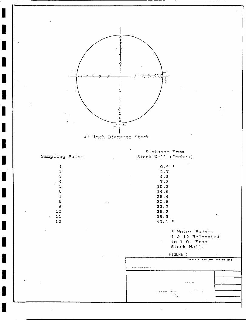
exhausted through a 41 inch diameter stack through the roof of the
body preparation plant. The sampling port locations were 0,8 stack
diameters upstream and approximately nine stack diameters
downstream from disturbances in the exhaust flow. A diagram of the I
stack is shown in Figure 1.
1 111. METHODS AND PROCEDURES
EPA Methods 1 and 2 were used to obtain the sampling port
locations and determine stack velocity and volumetric flowrate
respectively. Twenty-four points' was determined as the proper
number of sampling locations. Each point was sampled for 2.5
minutes, giving a total test time of 60 minutes per run. EPA
Method 5 was followed for sampling and analysis of particulates.
The Method 5 sampling train was assembled as shown in Figure :'
2 for each particulate test. A five foot probe with a heated pyrex
glass or stainless steel liner was used. The probe temperature was
monitored continuously during the test runs. Stack temperature
measurements were conducted at each point during the initial
velocity traverse and during sampling.
The first and second impingers were each charged with.100 ml
of distilled, deionized water; the third wasdry; and the fourth
was filled with known weight of indicator-grade silica gel.
Crushed ice was placed around the impingers during sampling to
maintain the temperature of the gas leaving the last impinger below
68°F.
I - A borosilicate glass fiber filter .(mainCaJ:ied . . :it' a temperature . ..s, ?':;; ''
>, '~ :-
between 225" and 275'F) was used for particulate matte'r collection.
I The filter temperature was monitored throughout the test.
I Leak tests were performed before and after each sampling run
by blocking the nozzle inlet. No leakage was observed at vacuum
I levels equal to or exceeding those experienced during the sampling
At the end of each run the volume of water collected in the
first three impingers was measured and the silica gel in the fourth
impinger was weighed to the nearest 0 . 5 gram to determine the
volume of water collected. All impingers were then rinsed and
charged for the next run.
The filter holder was removed and sealed for transport to the
laboratory. The sample nozzle and probe liner were brushed and
.rjnsed with acetone into a storage container. A new loaded filter . .~ . . .
holder was installed and the sampling train reassembled for the (
next run.
After returning to the laboratory, each filter and any loose
particulate matter was removed to a clean dry petri dish for
subsequent gravimetric analysis. The front half of the filter
holder was brushed and rinsed into the appropriate probe wash
container. The particulate filters for each run were oven dried
for 2 hours at 105'C, desiccated for 24 hours and weighed to
constant weight. The acetone wash volumes were measured and
transferred to tared 4 0 0 ml beakers and evaporated to dryness at
low heat and ambient pressure. The beakers were then cooled in a
desiccator and weighed to a constant weight. A portion of the
acetone used for component washing was analyzed by the same
procedures to determine blank residue.
APPENDIX A
TEST DATA AND CALCULATIONS

SUMMARY OF TEST DATA
I Plant:
I Source: Body Preo Soray Dryer
Emission:Particulate
RUN 1 RUN 2 RUN 3
Test Date:
1 Test Interval:
I Test Time. min.:
Stack Area. so. ft..:
Nozzle Diameter. in.:
Barometric Pressure. in. Hg.:
Absolute Stack Pressure. in. Hg.:
Volume Liouid Collected. ml.:
Stack Moisture (measured value). %
Stack Moisture (saturated value). %
Stack Gas Temoerature. deg F:
Samole Volume. DSCF:
Gas Velocity, FPS:
Gas Flowrate. ACFM:
Gas f low rate. DSCFM:
Particulate Collected. mg5
Emission Rate. I b / h r :
Percent 1sokinetic:X:

CALCULATIONS
PLANT : SOURCE: Body Preo Spray Dryer PARANETER:Particulate DATE : 10-13-94
RUN NO. 1 CD= 0.84 Y = 1.012 Dn= 0.246 inches An= 3.301E-04 so. ft. Pb = 29.97 in Ha Ps = 29.95 in Hg As = 9.164 so. ft. Time= 60 min Vm = 38.025 DCF Vm(COR)= 38.025' DCF dH= 1.44 in. HZ0 Tm= 531 dea R Ts= 608 deo R Vlc= 187.7 ml. SQRTdPavo= 0.7111 Mn= 0.0583 ma
38.4332 DSCF 8.8407 SCF 0.1870 0.24 29 assumed
26.9429 44.3264 FPS
17211 DSCFN 24372 ACFM 103.3 % 0.0234 gr/dscf 3.453 lb/hr
2 0.84 0.968 0.246 inches
3.301E-04 so. ft. 30.00 in Ha 29.98 in Hg' 9.164 so. ft;
60 min 36.656 DCF 36.656 DCF
1.23 in. H20 533 deo R 607 deg R
218.2 ml. 0.6852 0.0606 mo
35.3417 DSCF 10.2772 SCF 0.2253 0.23 29 assumed
26.5219 42.9797 FPS
15951 DSCFM 23631 ACFM 102.5 %
0.0265 gr/dscf 3.617 lb/hr
3 0.84 1.012 0.246 inches
3.301E-04 so. ft. 29.97 in Ha 29.95 in Hq 9.164 so. ft.
60 min 35.900 DCF 35.900 DCF
1.26 in. HZ0 :- 534 deq R 606 dea R
238.9 ml. 0.6839 0.0386 mq
36.0796 DSCF 11.2522 SCF 0.2377 0.23 29 assumed
26.4974 42.9108 FPS
15886 DSCFM 23594 ACFM 105.1 7.
0.0165 gr/dscf 2.248 ib/hr

I I
An:
I As: I Bws:
Ca:
I Cs: I Cs,,: I Cs12:
C(X):
1 Co: Dn:
1 E:
I E f :
1 Fd: 1 I :
Md:
1 Ns: 1 Mn:
1 pb: Ps:
1 0.3: 0s:
I R:
I I
SOURCE TESTING NOMENCLATURE AND DIMENSIONS
Cross sectional area of nozzle. ft.*2
Cross sectional area of stack. ft.*2
Water vapor in the gas stream. Drooortional by volume
Concentration of oarticulate matter in the stack gas at actual conditions. gr/acf
Concentration of oarticulate matter in the stack gas at standard conditions. gr/dscf
Concentration corrected to 50% excess air
Concentration corrected to 12% carbon dioxide
Concentration of X
Pitot tube coefficient
Diameter of nozzle. inches
Source emission rate. lbs/hr
Excess air
Ratio of oounds of Darticulate matter oer unit of heat combustion (oxygen based). lb/MBTU
Ratio of standard volume of gas oroduced Der unit of heat combustion (oxygen based). dscf/MBTU
Percent of isokinetic sampling
Nolec~~lar weioht of stack gas. dry basis. lb/lb-mole
Molecular weight of stack gas. wet basis. lb/lb-mole
Total oarticulate collected. less acetone blank correction. grams
Barometric oressure at test site. in. Hg
Absolute stack gas pressure. in. Hg
Volumetric flowrate. actual conditions. ACFM
Volumetric flowrate. dry at standard conditions. DSCFM
Beryllium emission rate. grams/day
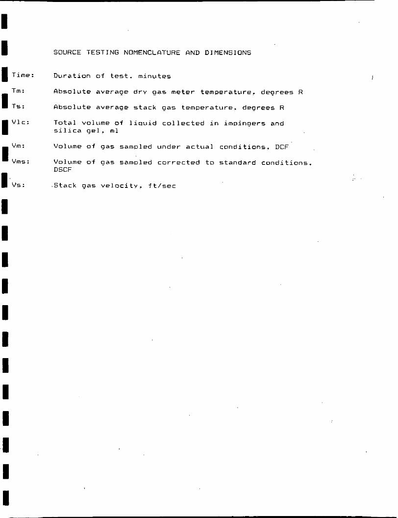
I I I Time:
Tm:
1 Ts: I Vlc:
1 Vms vm: :
I.vs: I I I I I I I I I I I I
SOURCE TESTING NOMENCLATURE AND DIMENSIONS
Duration of test. minutes
fibsolute average dry gas meter temperature, degrees R
Absolute average stack gas temperature. degrees R
Total volume of liquid collected in im~ingers and silica gel. ml
Volume of gas sampled under actual conditions. DCF
Volume of gas samoled corrected to standard conditions. DSCF
.Stack gas velocity. ft/sec
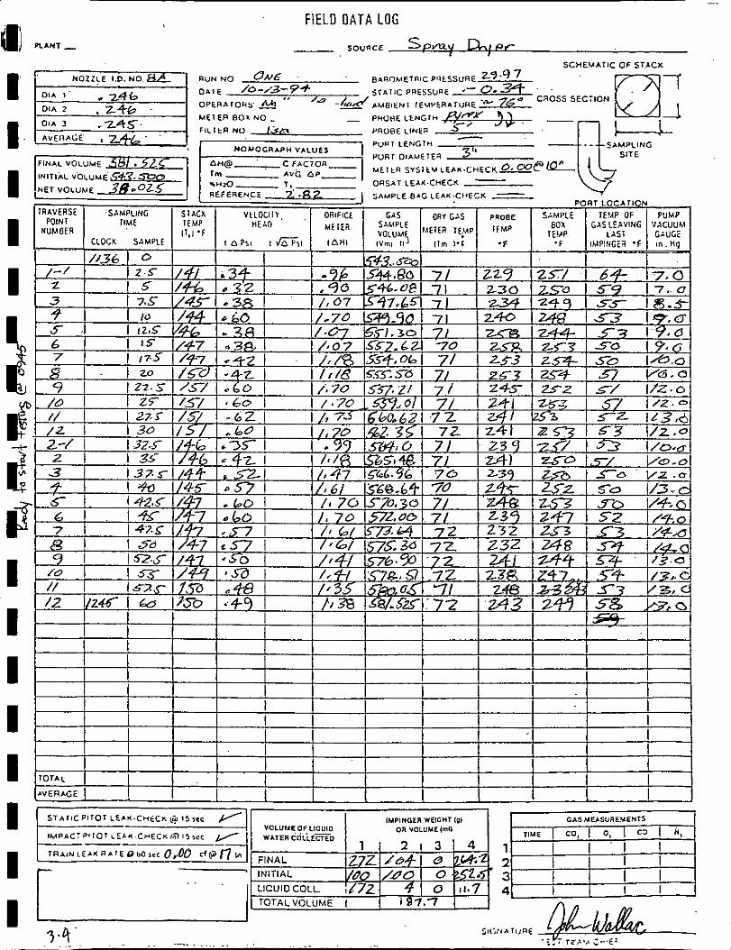
FIELD O A T A LOG
- S O ~ U C E Spmv D-.IPF SCHEMATIC O F STACK
nurr NO UUC saaoMETalc PlltSSuRE z9.9 A / O - / 3 - 9 4 jrnrlc PRESSUUE -- 0.3 - -
o ~ t n ~ r o u s r ~ t " 'a -&rC/ ,.UE,ENI , E ~ P ~ R ~ ~ , , H E W+ 7G6 SEC710N
MEIEFI 801 NO ..
PUUI LENGIN
PORT O I A U € I E ~ 3''
VOLUllEOF LlOUlO
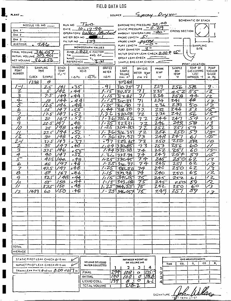
FIELD DATA LOG
SOuaCE
SCHEYATIC O F STACX
NOZZLE I D . NO. - R U N N O TWO' 8AROMETRIC P l l tSSURE x 0 '0°
DIIE 10- 17-94 s r x r l c PUESSURE - 0 .zq . . . 01A I' caoss SECTION
OPERAIOYS h/&~r /&&4 L u 8 l ~ ~ 1 IEUPERATIJRE *-'
- - MEI EFI ROK NO PMOHE L t N G T H 7' -- 8
PURT DIAMETER 3 " UEItFa S Y s l L u L E ~ K - C H E C K ~ C &-
**a- T, ORSAT LEAK-CHECK .-
SAMPLE B ' G LEAK.CIIECX PORT LOCATION
IRAVEASE . S~MPLING SIACX VtLCCl l l . ORIFICE ORY GAS PRCBE SAMPLE IEYP OF PUMP I POINT IIME IEMP nt:n SAMPLE BOX . GASLEAVING 'VACUUM Vn,IIMI IlETER TLMP
l i p I Us I NUMBER 11.1 .f IFMP LAST I GAUGE CLOCK SAMPLE
/ f l 9.50 3.q N Is7sl-/Sa ~414 I 1, S w I ! S 5 1 7 5 24Z zso 113 / z /+39 1 60 (YSa 1 M I ./ . M34krM-/ I 7b 299 ZS/ I/ 7
I 1 I I
AVERAGE I 1 1 1 1 I I 1 I 1 I 1 . j --
S T A T ~ C P I T O T LEA* C n t C K L? 1 5 r r c CASUUSUREUEH~~
1 M P A C T P I l O I L E ~ L C-ECI(15lI5sec
1 2 3 4

- . . .
IL FIELD DATA LOG

Client.
'LABOBATORY ANALYSIS . . . .
source Date /O/i?/s+
1
FILTER Run 1 Run 2 . Run 3 Blank
I.D. No. - /38 /39 I /* /5-7
Gross Weight, g 6 36 7p -3663 .3&73 1 ‘,3399 Gross Weight, g 36 7/ 3 6 6 /
0 3673 * 3399 Average Weight, g 3673 - 3662 3 L 73 - 3359 .- Tare Weight, g
e 3379 336q .3374 1.3398 Net Weight, g 1 . ~ 2 9 + - 02 9 8 . 02 9.9 1 .. CJOO/
ACETONE RINSE Run 1 I Run 2 Run 3 1 Blznk
I.D. NO. I P/Z 4 2 / ~ 4/4 I /62 Vol~me, ml /% ! 178 5 I /oo Gross Weight, g /72-3582 / ~ f i 0 ~ & / /ZZ &6/ 1 68- 6973 1 Gross Weight, g /7z.= / 6 ~ ~ 2 % z ? [/ZZ?LSP 1 @-6979 1 Average Gross, g 1 /72. m-3 /&+.0260 /LZ - '?%@ 69 74 1 Tare Weight, g
I OZ.. 3ag / ~ z , T P ~ /ZZ. 4/6 6 1 68- L 970 I
Acetone Residue, g . ow6 6007 ,0007 X I Net Weight, g - I 0.~239 - 6308 o o g 7
TOTAL PARTICULATE, g e 0583 2 6 606 #0386 -
ketone. Rinse Blank Residue= (blank weicht) (rinse volume) / (blznk volume)
Maximum ~llowable Residue=(0.00001 of zcetone weight) (0.7857 g/ml)
Each.-component was weighed to a constant weight, aeaning a difference of no more than 0.5 mg or 1 percent of total weight less tare weight, which- ever is greater, between two consecutive weichings, with no less than 6 hours of dessication time between weighings.
Comments :
APPENDIX B
V I S I B L E E M I S S I O N T E S T REPORT

- n b B ~ m h o n & k
<+~LJZ -, 3,5Jj &&Lib/, ~t(fiLJl4 3.c f+ 460rl~
I &f7 Prrfbld~ nd, m/:, m-nc & & / ~ r f u / Wuht o( tiM. Pf. M. to C h s ~ e r
nod 20 Mdoxeto .Pf.
k. End J b 4-4. Diresmcn to u. (Depreer)
I a& 1 ~ 9 7 7 End /jg Lk Inot w ~ ~ 0 2 .
0 3 sod -"t~;:~,u' (=$ F
I &I- cm Dintaon to 0 w o t m wnt h m WM wnt
non .a++ Qp n u t 9% SE End 20 cc L{P
DeenDe w.+fcf EnUpo $fly : fil ,ope/ 'OL1 " v'5.L" A" nm , Y, $,b/ w Yw? Fflq,lS. ,f/5;&
I * F o r Woter aonet ~ r n e
slan 'U / , ;+L~ End d ~ 3 i h IAnahnd~ a j t a a h o d n ~xaa
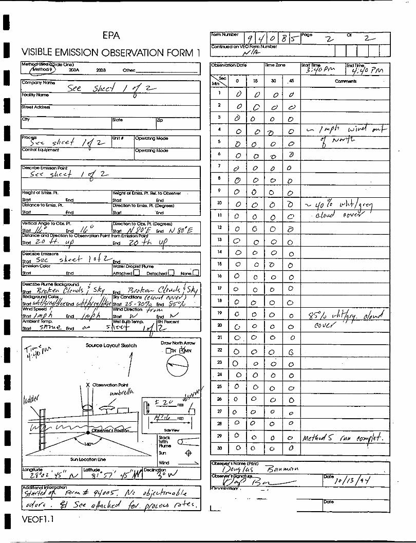
VISIBLE EMISSION OBSERVATION FORM 1
I I I I I I VEOFl . I
Me ma Other. -
C l x n r n N m W
See ~ / ? r c J / d 2' -ly-
Slreet Addnu.
cnv Sld* aP
PlOc JL shref / d z I MI* OperoTrgMa*1
h h d Eqipnem v OperoTrgMcde
Dernbe Emuon Pdnf
$si 5 t t c c t / a 2- u
Height d W. A. HeigM d EmLu.Pt.Rel.toC(ysw . aart b d sim w Woxe to h&. Fl. mrecnmto erk. A. (DOW-)
Sled End S t d ' w
vemcd wge to oba A. 0 mresmto Obi. Fi. (Degrees)
nod /A. 0 End /I.
W m s e w & Inm f l / ~ b ' ~ w @'E
to Obrervdm Pdnt I r a w o n nm Z-0 . U P w Zd k UP
I
3eanae -or. Slm S ~ L 5A-d- I 4 Lw EW+m Cdor Woter @o@et Ans
sort md A n m h a d f l DetahedO Mn,
oMn # u ~d ;c r -h - sL /~
ado/< : @ See off;lcLcd &,. i / b ~ s u / ; ? k c ,


APPENDIX C
PROCESS WEIGHT STATEMENT
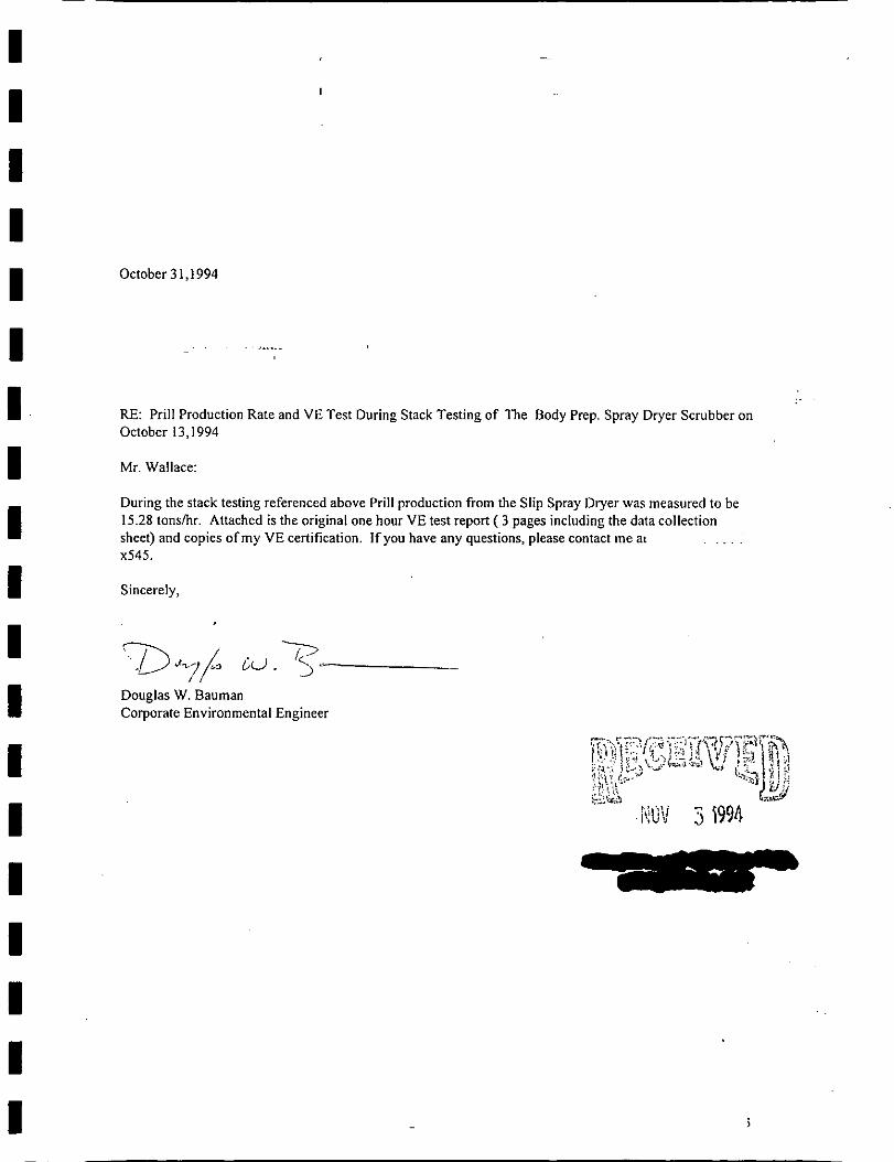
October 3 1,1994
RE: Prill Production Rate and VE Test During Stack Testing of The Body Prep. Spray Dryer Scrubber on October 13,1994
Mr. Wallace:
During the stack testing referenced above Prill production from the Slip Spray Dryer was measured to be 15.28 tonsthr. Attached is the original one hour VE test report ( 3 pages including the data collection sheet) and copies of my VE certification. If you have any questions, please contact me at . . . . x545.
Sincerely,
Douglas W. Bauman Corporate Environmental Engineer

APPENDIX D
CALIBRATION DATA

SUMMARY OF EQUIPMENT CALIBRATION
....................................................................... Equipment Calib. Date Place Method Results .......................................................................
Nozzle #8A 10/13/94 On-Site 3 measurements Dn=0.246 w/vernier caliper
Pitot Tube P-1 03/25/94
Pitot Tube P-3 03/25/94
console 01/17/94
Post-Test Check 10/31/94
(Console
EPA Method Cp=O. 84
EPA Method Cp=O. 84
Wet Test Meter Y=1.012 H@=1.929
Comparison to Dif f . <+l% ASTM Thermometer - +I%
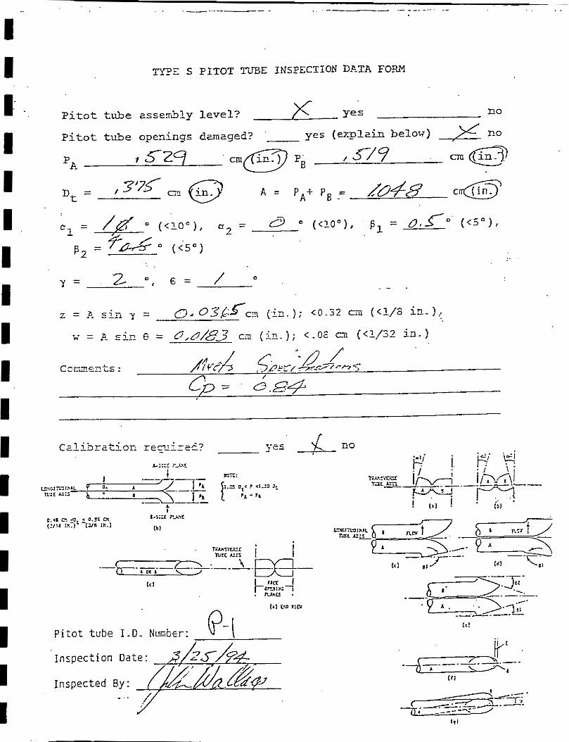
1 W Z S PITOT TUBE INSPECTION DATA FOPA
Pitot tube asserbly l eve l ? no
Pitot tube openings dzmaged? '- yes ( q l z i n below) ,% no
, s z q , s / 9 P~
/ '2 O , E = 0
Y = . - .
z = P. sin y = 0.036S-c~ c i ~ . 1; < O . ~ Z c m (<1/8 ic-
= p- _ci.n = 0,0/$33 C.7! (ip.); < - O E cil (<1/32 ia-
CCFZ.S__~~S : '-/ /
/?PYA ,<2Fr, --mc- *7
c, = . G.s.+
pi;ot t u b e I.D. Nunbcr: v- I Inspection Date:
I nspec ted By: ./

TYPE 5 EIT3T m E INSPECTION DE-TP. FOP21
pitot t&e assembly l eve l ? \I Y e s no
Pitot tllje o p e ~ i ~ g - c E ~ ~ z g e d ? yes ( e ? r p l ~ i n belor;) ra
560 m (in.) I Ll tiS cm ( i n . )
pitct t u b e I.D. Number: P -3 I n s p r c t i c n D ~ t e :
I nspec ted e:~:

I DGK Calibration
Technician: HARRY JOHNSON DATE:1/17/94
Control Box No. :
Barometer ("Hg): 29.990
SDGK:6835447
Ys: 0.9380
. . . . . . . . . . . . . . . . . . . . . . . . . . . . . . . . . . . . . . . . . . . . . . . . . . . . . . . . . . . . . . . . . . . . . . . . . . . . . . *Hd Net SOGH Net DGH SDGH DGX DGH DGH Time Vacuum
Volume Volume Temp In Out Avg. Setting Y dHa ("H20) (ft3) (ft3) ( F ) " ( F) ( F) ( F) (min) ('Hg) ( 'H20) [dHdl [Vsl [Vdl L tsl Itdl . . . . . . . . . . . . . . . . . . . . . . . . . . . . . . . . . . . . . . . . . . . . . . . . . . . . . . . . . . . . . . . . . . . . . . . . . . . . . .
0.50 5.706 5.634 67.0 67 67 67.0 15 3 1.010 1.9247 1.00 8.115 8.000 68.0 68 70 69.0 15 3 1.012 1.9068 1.50 10.591 10.424 68.0 72 ' 76 74.0 16 3 1.022 1.8962 2.00 12.896 12.829 68.0 73 77 75.0 17 3 1.012 1.9215 2.50 12.596 12.555 68.0 74 78 76.0 15 3 1.010 1.9564 3.00 13.765 13.714 68.0 74 78 76.0 15 3 1.009 1.5658
. . . . . . . . . . . . . . . . . . . . . . . . . . . . . . . . . . . . . . . . . . . . . . . . . . . . . . . . . . . . . . . . . . . . . . . . . . . . . . 1.012 1.929
dHd RANGE CRITERIA ..................................... . . . . . . . . . . . . . . . . . . . . . . . . . . . I I Thermocouple Check I I 0.069 <0.15"H20 I I I I
I I 75 F = 535 R I I I I ASTH: 68 F = 528 R I I I I I I I I DIFFERENCE % : 0.09 I I I I I I .....................................
SDGK= Standard Dry Gas Meter
I

I Recheclr of Orifice and DGM Calibration
Technician: Joseph Bouchard Date: .10-31-94
1 control BOX NO. : SDGM: 30598 -
Barometer ("HE): 30.070 Ys: 0.9990 - 1 Plant: -
................................................................. -Hd NetSDGbl NetDGH SDGM DGM DGM DGM Time Vacuum
Volume Volume Temp In Out Avg. Setting 1 i.,HZO) ift3) (ft3) ( F) ( F) ( F ) ( F ) (min) ( " H E ) CdHd1 CVsI . CVdl Ctsl C tdl
I ___-__________---------------------------------------------------
2.00 10.920 10.900 7E.O 7 5 75 75.0 15 7
2.00 10.990 11.000 7C.0 80 77 78.5 15 7
I ................................................................. ..................................... Y ( I)= 0.994 1 : Thermocouple Check , I , ,
I f I I 8 I I
, . Y ( % ) = 0.997 1 1 75 F = 535 R I !
t , , . ASTM: 79.5 F ~ 5 3 9 . H : ! Y (3 )= 0.998 ! ! , I
I * ,
t , DIFFERENCE: 0.02 t : , , 5 .
0.996 ! I I I Y(avgl= , , .....................................
Prior Y = 1.012
Diff .= 1.6%
Calibration Performed BY
&)FA/d Jos ph Bouchard
I Y=~V~~Ys*Phar*ltd+460)1/rVd'~(Phar+(dHd/l3.6)):~~ts+46~~~ SDGM= Standard Dry Gas Meter
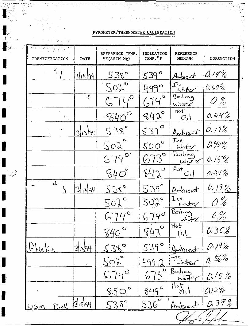
PYRO!ETER/THER'~OHETER CALIBRATION
APPENDIX E
CHAIN OF CUSTODY
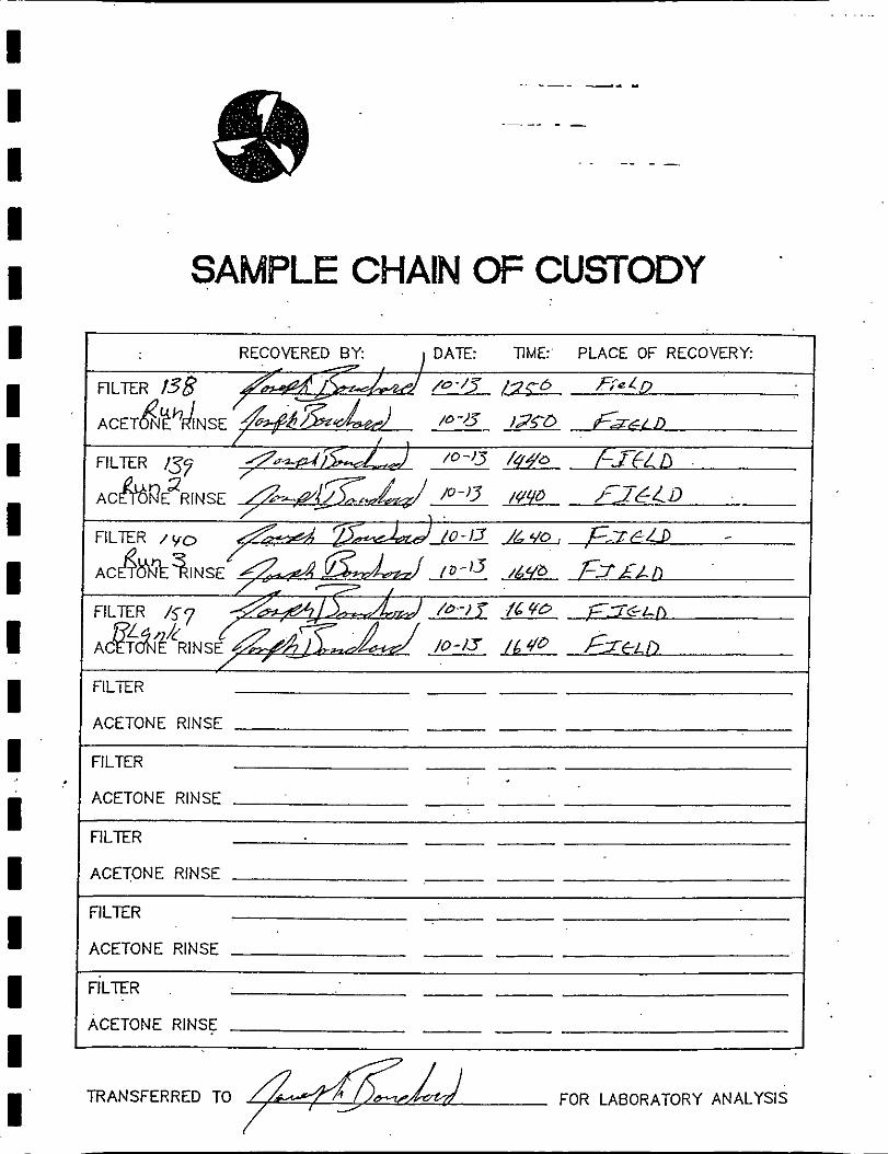
SAMPLE CHAIN OF CUSTODY
FILTER I ACETONE RlNSE I
I FILTER I ACETONE RlNSE
FILTER
ACETONE RlNSE
FILTER
ACETONE RlNSE
ACETONE RlNSE 1 TRANSFERRED TO FOR LABORATORY ANALYSIS

APPENDIX F
OPERATING PERMIT
APPLICANT : --
r I . . . .. . . . . . - . . ,
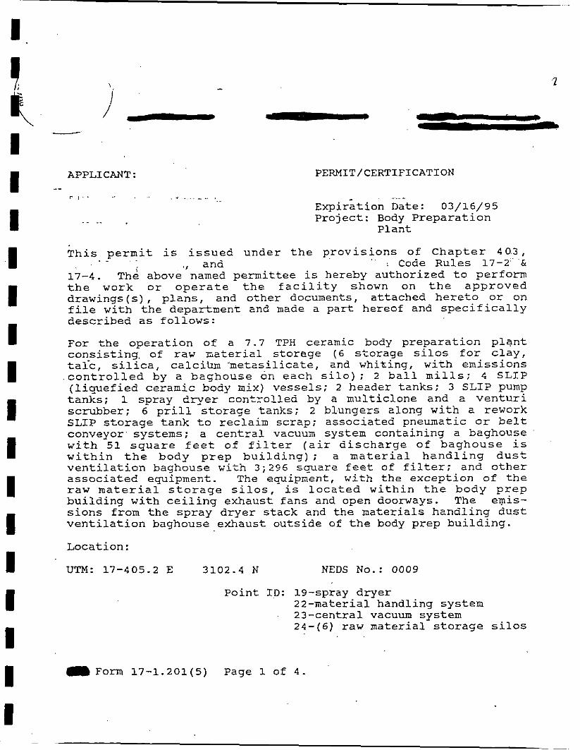
~ x p i r s t i o n Date: 03/16/95 P r o j e c t : Body P r e p a r a t i o n
P l a n t
T h i s p e r m i t i s i s s u e d u n d e r t h e p r o v i s i o n s o f C h a p t e r 40.3, . - . . . . , and : Code R u l e s 1 7 - 2 " & 17-4. hi above named p e r m i t t e e is hereby a u t h o r i z e d t o p e r f o r m t h e work o r o p e r a t e t h e f a c i l i t y shown on t h e a p p r o v e d d r a w i n g s ( s ) , p l a n s , and o t h e r documents, a t t a c h e d h e r e t o o r on f i l e w i t h t h e depa r tmen t and made a p a r t hereof and s p e c i f i c a l l y d e s c r i b e d a s f o l l o w s :
F o r t h e o p e r a t i o n of a 7.7 TPIi ceramic body p r e p a r a t i o n p l a n t c o n s i s t i n g . o f r a w z i a t e r i a l s t o r e g e ( 6 s t o r a g e s i l o s f o r c l a y , t a l - c , s i l i c a , c a l c i h - m e t a s i l i c a t e , and w h i t i n g , w i t h e m i s s i o n s c o n t r o l l e d by a b a g h o u s e on e a c h s i l o ) ; 2 b a l l m i l l s ; 4 S L I P ( l i q u e f i e d c e r a m i c body mix) v e s s e l s ; 2 h e a d e r t a n k s ; 3 SLIP pump t a n k s ; 1 s p r a y d r y e r c o n t r o l l e d by a m u l t i c l o n e and a v e n t u r i scrubber; 6 p r i l l s t o r a g e t a n k s ; 2 b l u n g e r s a long w i t h a rework SLIP s t o r a g e t a n k t o r e c l a i m s c r a p ; a s s o c i a t e d pneumat ic o r b e l t conveyor . sy s t ems ; a c e n t r a l vacuum system c o n t a i n i n g a baghouse w i t h 51 s q u a r e f e e t o f f i l t e r ( a i r d i s c h a r g e o f b a g h o u s e i s w i t h i n t h e b o d y p r e p b u i l d i n g ) ; a m a t e r i a l h a n d l i n g d u s t v e n t i l a t i o n baghouse w i t h 3;296 s q u a r e f e e t o f f i l t e r ; and o t h e r a s s o c i a t e d equipmerit. The equipment, w i t h t h e e x c e p t i o n o f t h e r a w m a t e r i a l s t o r a g e s i l o s , i s l o c a t e d w i t h i n t h e b o d y p r e p b u i l d i n g w i t h c e i l i n g e x h a u s t f a n s and open doorways. The emis- s i o n s f rom t h e s p r a y d r y e r s t a c k and t h e m a t e r i a l s h a n d l i n g d u s t v e n t i l a t i o n baghouse e x h a u s t o u t s i d e of t h e body p r e p b u i l d i n g .
L o c a t i o n :
UTM: 17-405.2 E 3102.4 N NEDS No.: 0009
P o i n t ID: 19-spray d r y e r 22-mater ia l h a n d l i n g s y s t e m 2 3 - c e n t r a l vacuum sys tem 24-(6) r a w m a t e r i a l s t o r a g e s i l o s
Form 17-1.201(5) Page 1 of 4 .

I
I PERMITTEE: I . 1 :.
. . . I
1 -- SPECIFIC CONDITIONS:
PERMIT NO. : - - - PROJECT: BOay Prep. P l a n t
1. A p a r t of t h i s permi t is t h e a t t ached 15 General Condi t ions
2 . P r i l l p r o d u c t i o n by t h e body p r e p z r a t i o n p l a n t s h z l l n o t exceed. 7.7 TPH.
3 . A s r eques t ed by t h e pe rmi t t ee , t h e maximum p a r t i c u l a t e e m i s - s i o n s from t h e sp ray dryer v e n t u r i scrubber s h a l l n o t exceed 3 . 6 l b s / h r (10.5 TPY) and 20% opac i ty . This source s h a l l be t e s t e d f o r p a r t i c u l a t e s and opac i t y a t i n t e r v a l s of 1 2 months from t h e d a t e November 1 4 , 1989. Submit t h e t es t da t a t o t h e A i r S e c t i o n of t h e Southwest D i s t r i c t O f f i ce wi th in 4 5 days of such t e s t i n g ( S u b s e c t i o n 1 7 - 2 . 7 0 0 ( 2 ) , F l o r i d a A d m i n i s t r a t i v e C o d e ) . The p r e s s u r e drop a c r o s s t h e scrubber s h a l l be a t l e a s t 7 i n c h e s of wa te r , gauge.
4 . A s requested by t h e pe rmi t t e e , r h e maximum p a r t i c u l a t e e m i s - s i o n s from t h e m a t e r i a l hzndl ing dus t v e n t i l a t i o n baghouse s h a l l no t exceed 1.7 l b s / h r (5.0 TPY) and t h e maximum p a r t i c u l a t e e m i s - s i o n s from t h e c e n t r a l vacuum system baghouse s h a l l n o t exceed 0.04 l b s / h r (0.10 TPY). Because of t h e expense and complexi ty of conduct ing a s t a c k t e s t on minor sourcos of p a r t i c u l a t e m a t t e r , t h e Depar tment w a i v e s t h e - r e q u i r e m e n t f o r a s t a c k t e s t . The a l t e r n a t i v e s t a n d a r d s e t f o r t h by t h i s p rov i s ion e s t a b l i s h e s a v i s i b l e emiss ion l i m i t a t i o n no t t o exceed an opac i t y o f 5%. T e s t t h e s e s o u r c e s f o r opac i t y a t i n t e r v a l s of 12 months from t h e d a t e November 1 4 , 1589. Submit t h e t e s t da t a t o t h e A i r S e c t i o n of t h e - D i s t r i c t O f f i c e w i t h i n 45 d a y s o f s u c h t e s t i n g (Subsec t ion 17-2.700 (2 ) , ' -, ,
5. There s h a l l b e no v i s i b l e emissions (5% o p a c i t y ) from t h e raw m a t e r i a l s t o r a g e s i l o s . A v i s i b l e emissions t e s t s h a l l be performed annua l l y on t h e t a l c s i l o dur ing loading. Submit t h e - - . tes t d a t a t o t h e - " ~ i r - ' ~ e ~ i o n ~ t h e J -
. . . ~ - --- ---& wi th in . . 45 days o f such t e s t i n g - . . - i , . . - . . . . - .
"-+. - - - Page 2 of 4 .
PERMITTEE : . - PERMIT NO. : - - . . PROJECT: Body Prep. Plant
-- SPECIFIC CONDITIONS (cont'd) :
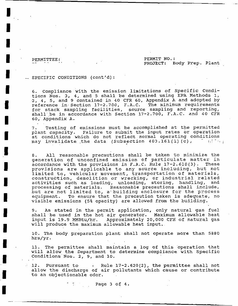
6. Compliance with the emission limitations of Specific Condi- tions Nos. 3, 4, and 5 shall be determined using EPA Methods 1, -2, 4, 5, and 9 contained- in 40 CFR 60, Appendix A and adopted by reference in. Section 17-2.700, F.A. C. The rcininum requirements for stack sampling facilities, source sampling and reporting, shal1,be in accordance with Section 17-2.700, F.A.C. and $0 CFR 60,' Appendix A.
. .
7. Testing of emissions must be accomplished at the permitted plant capacity. Failure to submit the input rates or operation at conditions which do not reflect normal operating conditions may invalidate .the data (Subs,ection 403.161 (1) (c) , . -
1 , : / i
8. All reasonable precautions shall be taken to minimize the generation of unconfined emission of particulate matter in accordance with the provisions in F.A.C. Rule 17-2.610(3). These provisions zre applicable to any source including, but not limited to, vehicular movement, transportation of materials, construction, demolition or wrecking, or industrial related activities such as loading, unloading, storing, handling, and processing of materials. Reasonable precautions shall include, but are not limited to, a'building enclosure for the process equipment. To ensure that the precaution taken is adequate, no visible emissions (5% opacity) are allowed from the building.
9. As stated in the permit application, only natural gas fuel shall be used in the hot air generator. Maximum allowable heat input is 19.9 MMBtu/hr. Approximately 20,000 CFH of natural gas will produce the maximum allowable heat input.
10. The body preparation plant shall not operate more than 5880 hrs/yr.
11. The permittee shall maintain a log of this operation that will allow the Department to determine compliance with Specific Conditions Nos. 2, 9, and 10. . .
12. Pursuant to Rule 17-2.620(2), the permittee shall not allow the discharge of air pollutants which cause or contribute to an objectionable odor.
- ., , . . Page 3 of 4.

PERMITTEE :
-- SPECIFIC CONDITIONS (cont18) :
PERMIT NO. : - - - - PROJECT: Body Prep. Plant
13. The 3ffice of the Department of Environ- mental Regulation shall be notified in writing 15 days prior to compliance testing.
.. .
14. Submit'for this source, each calendar year, on or before March 1, an emission report for the preceding calendzr,year containing the following info-mation:
(A) Annual amount of materizls and/or fuels utilized.. (B) Annual emissions (note czlcnlation Szsis). (C) Any changes in the info=ztion contained in the permit
application.
This report shall be submitted to the Air Section of the ' District of the Departneni of Environmentzl Reculation.
15. An application to renew this opergtinc permit shall be sub- mitted to the Department sixty (60) days prior to expiration date of this permit.
Issued this )v day of 1990.
\
Richard D. Garrity, Ph.D. Deputy Assistant Secretary
1 ,: : --. -I) Page 4 of 4 .
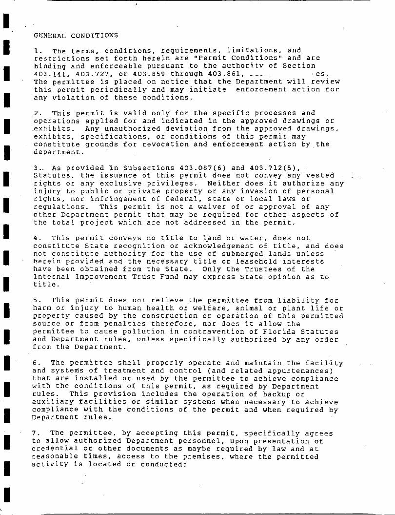
GENERAL CONDITIONS
1. The terms, conditions, requirements, limitations, and restrictions set forth herein are "Permit Conditions' and are binding and enforceable pursuant to the authoritv of Section 403.141, 403.727, or 403.859 through 403.861, 2es. The permittee is placed on notice that the Department will review this permit periodically and may initiate enforcement action for any violation of these conditions.
2. This permit is valid only for the specific processes and operations applied for and indicated in the approved drawings or .exhibits. Any unauthorized deviation from the approved drawings, exhibits, specifications, or conditions of this permitmay constitute grounds for revocation and enforcement action by the department .. 3.. As provided i n Subsections 403.087(6) and 403.712(5), 1
Statutes, the issuance of this permit does not convey any vested :..
rights or any exclusive privileges. Neither does .it authorize any injury to public or private property or any invasion of personal rights, nor infringement of federal, state or local laws or regulations. This permit is not a waiver of or approval of any other Department permit that may be required for other aspects of the total project which are not addressed in the permit.
4. This permit conveys no title to lpnd or water. does not constitute State recognition or acknowledgement of title, and does not constitute authority for the use of submerged lands unless herein provided and the necessary title or leasehold interests have been obtained from the State. Only the Trustees of the Internal Improvement Trust Fund may express State opinion as to title.
5. This permit does not relieve the permittee from liability for harm or injury to human health or welfare, animal or plant life or property caused by the construction or operation of this permitted source or from penalties therefore. nor does it allow the permittee to cause pollution in contravention of Florida Statutes and Department rules, unless specifically authorized by any order from the Department.
6. The permittee shall properly operate and maintain the facil:ity and systems of treatment and control (and related appurtenances) that are installed or used by the permittee to achieve compliance with the conditions of this permit, as required by Department rules. This provision includes the operation of backup or auxiliary facilities or similar systems when-necessary to achieve compliance with the conditions of.the permit and when required by Department rules.
7. The permittee, by accepting this permit, specifically agrees to allow authorized Department personnel, upon presentation of credential or other documents as maybe required by law and at reasonable times, access to the premises, where the permitted activity is located or conducted:

GENERAL CONDITIONS (can't):
12. This permit or a copy thereof shall be kept at the work site of the permitted activity.
13. This permit also constitutes: ( ) Determination of Best ~vailable Control
Technology (BACT)
- - ( ) Determination of Prevention of significant Deterioration (PSD)
( ) Certification of Compliance with State Water Quality Standards (Section 401. PL 92-500)
( ) Compliance with New Source Performance Standards . .
14. T h e permittee shall comply with the following:
a. - U p o n request, the permittee shall furnish all records and plans required under Department rules. During enfocement actions, the retention period for all records will be extended automatically, unless otherwise stipulated by the Department.
b. The permittee. shall retain at the facility or other location designated by this permit records of all monitoring information (including all calibration and maintenance records and all original strip chart recordings for continuous monitoring instrumentation), copies of all reports required by this permit, and records of all data used to complete the application for this permit. These materials shall be retained at least three years from the date of the sample, measurement. report or application unless otherwise specified by Department rule.
c. Records of monitoring information shall include:
-the date, exact place, and time of sampling or measurement; -the person responsible for performing the sampling or measure-; ments;
-the date(s) analyses were performed; -the person responsible for performing the analyses; -the analytical techniques or methods used: and -the results of sukh analyses.
15. When requested by the department, the permittee shall within a reasonable time furnish any information required by law which is needed to determine compliance with the permit. If the permittee becomes aware that relevant facts were not submitted or were incorrect in the permit application or in any report to the department, such facts or information shall be submitted or corrected promptly.