Embed Size (px)
Citation preview
Verizon 4G LTE Network Extender 2 for Enterprise
User Guide 3.4 Network Systems
Samsung Electronics America
Document Version 1.0 March 2019
Intellectual Property All Intellectual Property, as defined below, owned by or which is otherwise the property of Samsung or its respective suppliers relating to the SAMSUNG device, including but not limited to, accessories, parts, or software relating thereto (the “4G LTE Network Extender 2 for Enterprise”), is proprietary to Samsung and protected under federal laws, state laws, and international treaty provisions. Intellectual Property includes, but is not limited to, inventions (patentable or unpatentable), patents, trade secrets, copyrights, software, computer programs, and related documentation and other works of authorship. You may not infringe or otherwise violate the rights secured by the Intellectual Property. Moreover, you agree that you will not (and will not attempt to) modify, prepare derivative works of, reverse engineer, decompile, disassemble, or otherwise attempt to create source code from the software. No title to or ownership in the Intellectual Property is transferred to you. All applicable rights of the Intellectual Property shall remain with SAMSUNG and its suppliers.
Open Source Software Some software components of this product, including but not limited to ‘PowerTOP’ and ‘e2fsprogs’, incorporate source code covered under GNU General Public License (GPL), GNU Lesser General Public License (LGPL), OpenSSL License, BSD License and other open source licenses. To obtain the source code covered under the open source licenses, please visit: http://opensource.samsung.com.
Disclaimer of Warranties; Exclusion of Liability EXCEPT AS SET FORTH IN THE EXPRESS WARRANTY CONTAINED ON THE WARRANTY PAGE ENCLOSED WITH THE PRODUCT, THE PURCHASER TAKES THE PRODUCT “AS IS”, AND SAMSUNG MAKES NO EXPRESS OR IMPLIED WARRANTY OF ANY KIND WHATSOEVER WITH RESPECT TO THE PRODUCT, INCLUDING BUT NOT LIMITED TO THE MERCHANTABILITY OF THE PRODUCT OR ITS FITNESS FOR ANY PARTICULAR PURPOSE OR USE; THE DESIGN, CONDITION OR QUALITY OF THE PRODUCT; THE PERFORMANCE OF THE PRODUCT; THE WORKMANSHIP OF THE PRODUCT OR THE COMPONENTS CONTAINED THEREIN; OR COMPLIANCE OF THE PRODUCT WITH THE REQUIREMENTS OF ANY LAW, RULE, SPECIFICATION OR CONTRACT PERTAINING THERETO. NOTHING CONTAINED IN THE INSTRUCTION MANUAL SHALL BE CONSTRUED TO CREATE AN EXPRESS OR IMPLIED WARRANTY OF ANY KIND WHATSOEVER WITH RESPECT TO THE PRODUCT. IN ADDITION, SAMSUNG SHALL NOT BE LIABLE FOR ANY DAMAGES OF ANY KIND RESULTING FROM THE PURCHASE OR USE OF THE PRODUCT OR ARISING FROM THE BREACH OF THE EXPRESS WARRANTY, INCLUDING INCIDENTAL, SPECIAL OR CONSEQUENTIAL DAMAGES, OR LOSS OF ANTICIPATED PROFITS OR BENEFITS.
Modification of Software SAMSUNG IS NOT LIABLE FOR PERFORMANCE ISSUES OR INCOMPATIBILITIES CAUSED BY YOUR EDITING OF REGISTRY SETTINGS, OR YOUR MODIFICATION OF OPERATING SYSTEM SOFTWARE.
USING CUSTOM OPERATING SYSTEM SOFTWARE MAY CAUSE YOUR DEVICE AND APPLICATIONS TO WORK IMPROPERLY. YOUR CARRIER MAY NOT PERMIT USERS TO DOWNLOAD CERTAIN SOFTWARE, SUCH AS CUSTOM OS.
Samsung Electronics America (SEA), Inc Address: 85 Challenger Road Ridgefield, New Jersey 07660
Phone: 1-800-SAMSUNG (726-7864) Phone: 1-888-987-HELP (4357)
Internet Address: www.samsung.com
©2019 Samsung Electronics America, Inc. Samsung is a registered trademark of Samsung Electronics Co., Ltd.
Do you have questions about your Samsung Mobile Device? For 24 hour information and assistance, we offer a new FAQ/ARS System (Automated Response System) at: www.samsung.com/us/support
Verizon 4G LTE Network Extender 2 for Enterprise User Guide v1.0 iv Copyright © 2019, All Rights Reserved.
Contents
Preface viii Relevance ....................................................................................................................................... viii Conventions in this Document ....................................................................................................... viii Revision History ............................................................................................................................... ix Organization of This Document ...................................................................................................... ix Related Documentation .................................................................................................................. ix Personal and Product Safety ............................................................................................................ x
Chapter 1 Getting Started 1 Introduction ..................................................................................................................................... 1 Features ........................................................................................................................................... 1 System Requirements ...................................................................................................................... 3 Network Extender Basics ................................................................................................................. 4
Chapter 2 Network Extender Setup 10 Setup Procedure ............................................................................................................................. 10 Startup Sequence ........................................................................................................................... 15 Indoor GPS Antenna ....................................................................................................................... 20 Outdoor GPS Antenna .................................................................................................................... 22 PoE Device ...................................................................................................................................... 24 RF Antenna Extension .................................................................................................................... 25 PTP Extension for Location Information Acquisition .......................... Error! Bookmark not defined. Making a Call .................................................................................................................................. 29
Chapter 3 The Network Extender Admin Website (Local) 30 PC Requirements ............................................................................................................................ 30 Admin Website Access ................................................................................................................... 30 Admin Website Overview .............................................................................................................. 33 Home .............................................................................................................................................. 40 Connected Devices ......................................................................................................................... 42 Settings ........................................................................................................................................... 45 The About Page .............................................................................................................................. 64
Chapter 4 Configuring Your Device 70 Firewall Settings ............................................................................................................................. 70 Firewall Rules for the Network Extender for Business ................................................................... 71
Chapter 5 Troubleshooting 76 STATUS LED .................................................................................................................................... 76 Alarms and Troubleshooting .......................................................................................................... 78
Chapter 6 Deployment Guide 82 Single 4G LTE Network Extender Placement .................................................................................. 84 Dual 4G LTE Network Extender Placement .................................................................................... 86
Appendix A Outdoor GPS Antenna Installation 90 GPS Antenna System Configuration ............................................................................................... 90 Signal Interference ....................................................................................................................... 102 GPS Antenna Installation.............................................................................................................. 104 Grounding the Optional GPS Arrestor .......................................................................................... 110
Contents
Verizon 4G LTE Network Extender 2 for Enterprise User Guide v1.0 v Copyright © 2019, All Rights Reserved.
Appendix B Acronyms 112
Contents
Verizon 4G LTE Network Extender 2 for Enterprise User Guide v1.0 vi Copyright © 2019, All Rights Reserved.
List of Figures
Figure 1. Verizon Wireless 4G LTE Network Extender 2.................................................................................. 1 Figure 2. Box Contents .................................................................................................................................... 2 Figure 3. Optional Wall and Ceiling Mount Bracket (sold separately) .............. Error! Bookmark not defined. Figure 4. Components - Front and Rear View ................................................................................................. 4 Figure 5. Network Extender Placement ............................................................ Error! Bookmark not defined. Figure 6. Connect the Ethernet Cable and Power ............................................. Error! Bookmark not defined. Figure 7. Quick Reference Icons .................................................................................................................... 34 Figure 8. Network Extender Sign In Pop-Up Window ................................................................................... 36 Figure 9. Password Change Warning Message Pop-up Window .................................................................. 37 Figure 10. Network Extender Forgot Admin Password Window .................................................................... 38 Figure 11. Network Extender Security Challenge Pop-up Window ................................................................. 38 Figure 12. The Network Extender Home Page ................................................................................................ 40 Figure 13. The Network Extender Connected Devices Page in Open Mode ................................................... 42 Figure 14. The Network Extender Connected Devices Page in Hybrid or Closed Mode ................................. 43 Figure 15. The Network Extender Network Settings Tab ................................................................................ 45 Figure 16. The Network Extender Advanced Settings Tab .............................................................................. 48 Figure 17. The Network Extender Change Admin Password Tab .................................................................... 54 Figure 18. The Network Extender Time Zone Tab ........................................................................................... 56 Figure 19. The Network Extender Certificate Management Tab .................................................................... 58 Figure 20. Settings-Certificate Management-Reset Certificate Popup Window ............................................. 59 Figure 21. The Network Extender Reset Tab................................................................................................... 62 Figure 22. Complete Restart & Quick Restart & Factory Error Pop-up Window (Case 1: Exist E911 call(s)) .. 63 Figure 23. Complete Restart & Quick Restart & Factory Error Pop-up Window (Case 2: Exist Active User call(s)) ....................................................................................................................................................... 63 Figure 24. The Network Extender Status & Alerts Tab.................................................................................... 64 Figure 25. The Network Extender GPS Tab ......................................................... Error! Bookmark not defined. Figure 26. The Network Extender GPS Tab - The number of non-zero satellite signals ... Error! Bookmark not defined. Figure 27. The Network Extender GPS Tab - GPS Signal Quality ......................... Error! Bookmark not defined. Figure 28. The Network Extender Performance Tab ....................................................................................... 67 Figure 29. The Support Tab ............................................................................................................................. 69 Figure 30. Connect the GPS Arrestor and Line Amplifier .................................... Error! Bookmark not defined. Figure 31. Example of a Common GPS Antenna System Configuration .......................................................... 90 Figure 32. GPS Cable Configuration Case #1 ................................................................................................... 94 Figure 33. GPS Cable Configuration Case #2 ................................................................................................... 95 Figure 34. The Network Extender GPS Arrestor Cable Connection Case #1 ................................................... 97 Figure 35. The Network Extender GPS Arrestor Cable Connection Case #2 ................................................... 98 Figure 36. The Network Extender GPS Arrestor Cable Connection Details..................................................... 99 Figure 37. GPS Arrestor GPS Antenna Cable Connection Detail ................................................................... 100 Figure 38. GPS Antenna Installation.............................................................................................................. 101 Figure 39. GPS Antenna Installation (Wall) ................................................................................................... 105 Figure 40. GPS Antenna Installation (Floor) .................................................................................................. 106 Figure 41. Fixing GPS Bulkhead ..................................................................................................................... 108 Figure 42. Fixing the GPS Arrestor ................................................................................................................ 109 Figure 43. Connection of the GPS Arrestor Ground Cable ............................................................................ 111
Contents
Verizon 4G LTE Network Extender 2 for Enterprise User Guide v1.0 vii Copyright © 2019, All Rights Reserved.
List of Tables
Table 1. Network Extender external port ...................................................................................................... 4 Table 2. The recommended PoE specification ............................................................................................. 24 Table 3. The description of external RF antenna port ................................................................................. 26 Table 4. LMR-400 Cable assembly attenuation ........................................................................................... 27 Table 5. Admin Website Initial Access Window ........................................................................................... 34 Table 6. The Network Extender Home Page ................................................................................................ 40 Table 7. The Network Extender Connected Devices .................................................................................... 44 Table 8. The Network Extender Network Settings Tab ................................................................................ 46 Table 9. The Network Extender Advanced Settings Tab .............................................................................. 50 Table 10. The Network Extender GPS/Time Server Tab ................................................................................ 52 Table 11. The Network Extender Change Admin Password Tab .................................................................... 54 Table 12. The Network Extender Time Zone Tab ........................................................................................... 56 Table 13. Time Zone Information .................................................................................................................. 57 Table 14. The Network Extender Certificate Management Tab .................................................................... 58 Table 15. The Network Extender Reset Tab................................................................................................... 62 Table 16. The Network Extender Status & Alerts Tab.................................................................................... 66 Table 17. The Network Extender Start Up Progress ...................................................................................... 66 Table 18. The Network Extender Performance Tab ....................................................................................... 68 Table 19. The Support Tab ............................................................................................................................. 69 Table 20. Destination Ports ............................................................................................................................ 70 Table 21. Firewall Settings ............................................................................................................................. 70 Table 22. Alarms in the Network Extender Admin Website (Local) ............................................................... 78 Table 23. The Network Extender Range for Single Network Extender .......................................................... 82 Table 24. The Network Extender Spacing for Additional Placements ........................................................... 86 Table 25. GPS Antenna System Configuration ............................................................................................... 90 Table 26. GPS Cable Connection .................................................................................................................... 91 Table 27. Identification Tag of GPS Cable ...................................................................................................... 93 Table 28. Optional GPS Bulkhead Fixing Parts and Tools ............................................................................. 107 Table 29. GPS Arrestor Fixing Parts and Tools ............................................................................................. 109 Table 30. Grounding the GPS Arrestor (MGB GPS Arrestor) ........................................................................ 110
Verizon 4G LTE Network Extender 2 for Enterprise User Guide v1.0 viii Copyright © 2019, All Rights Reserved.
Preface
This user guide describes an overview of 4G LTE Network Extender 2 for Enterprise, including installation, setup procedure and troubleshooting.
Relevance This user guide applies to the following products/software
Model Release SLS-BU10G 3.3
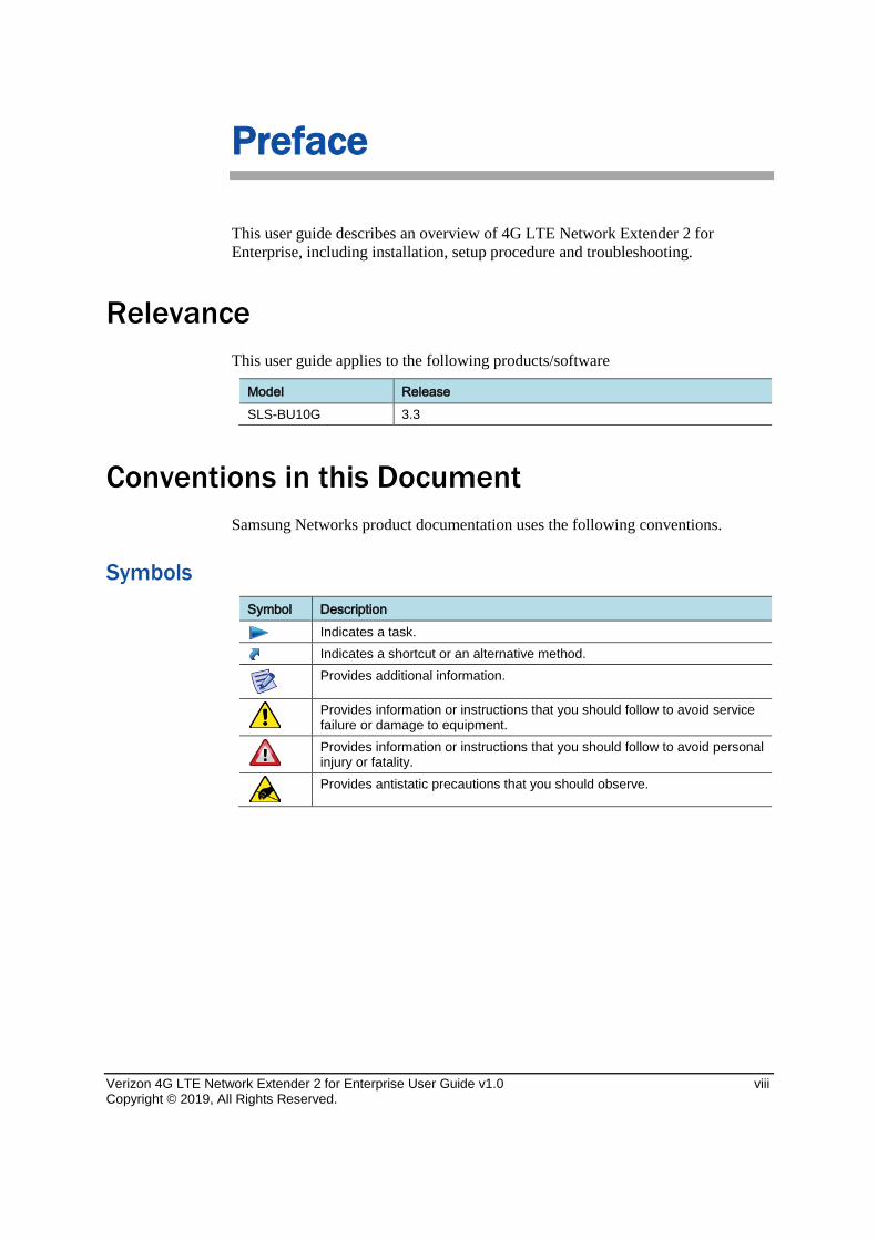
Conventions in this Document Samsung Networks product documentation uses the following conventions.
Symbols Symbol Description
Indicates a task.
Indicates a shortcut or an alternative method.
Provides additional information.
Provides information or instructions that you should follow to avoid service failure or damage to equipment.
Provides information or instructions that you should follow to avoid personal injury or fatality.
Provides antistatic precautions that you should observe.
Chapter 1 Getting Started
Verizon 4G LTE Network Extender 2 for Enterprise User Guide v1.0 ix Copyright © 2019, All Rights Reserved.
Revision History The following table lists all versions of this document.
Version Date Description 1.0 June 2017 First version
Organization of This Document Section Title Description Chapter 1 Getting Started Provides an overview of the Network
Extender. Chapter 2 Device Setup Describes the procedures needed to
set up the Network Extender. Chapter 3 The Network Extender Admin
Website (Local) Describes the Network Extender Admin Website (Local).
Chapter 4 Configuring Your Device Provides detailed information regarding firewall settings.
Chapter 5 Troubleshooting Provides information to troubleshoot STS LED statuses.
Appendix A Acronyms List of terms.
Related Documentation • Verizon 4G LTE Network Extender 2 for Enterprise Quick Start Guide
• Verizon 4G LTE Network Extender 2 for Enterprise Product, Safety and Warranty
• Verizon 4G LTE Network Extender 2 for Enterprise Installation Manual
Chapter 1 Getting Started
Verizon 4G LTE Network Extender 2 for Enterprise User Guide v1.0 x Copyright © 2019, All Rights Reserved.
Personal and Product Safety
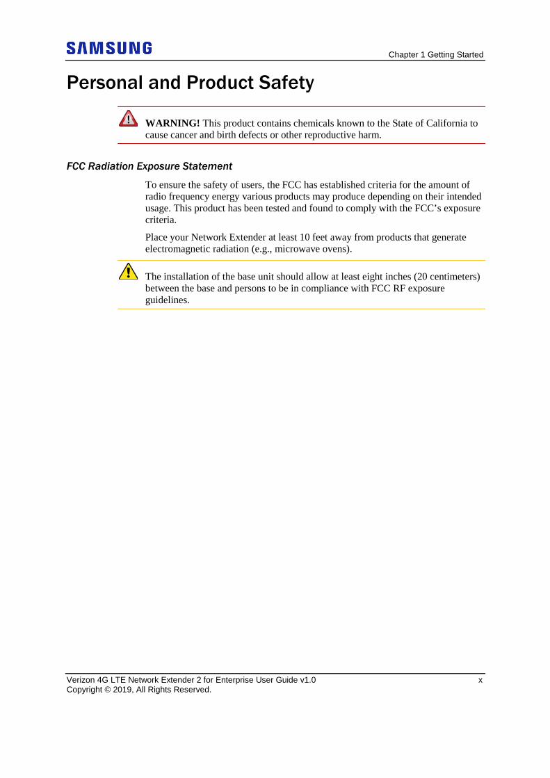
WARNING! This product contains chemicals known to the State of California to cause cancer and birth defects or other reproductive harm.
FCC Radiation Exposure Statement
To ensure the safety of users, the FCC has established criteria for the amount of radio frequency energy various products may produce depending on their intended usage. This product has been tested and found to comply with the FCC’s exposure criteria.
Place your Network Extender at least 10 feet away from products that generate electromagnetic radiation (e.g., microwave ovens).
The installation of the base unit should allow at least eight inches (20 centimeters) between the base and persons to be in compliance with FCC RF exposure guidelines.
Verizon 4G LTE Network Extender 2 for Enterprise User Guide v1. 0 1 Copyright © 2019, All Rights Reserved.
Chapter 1 Getting Started
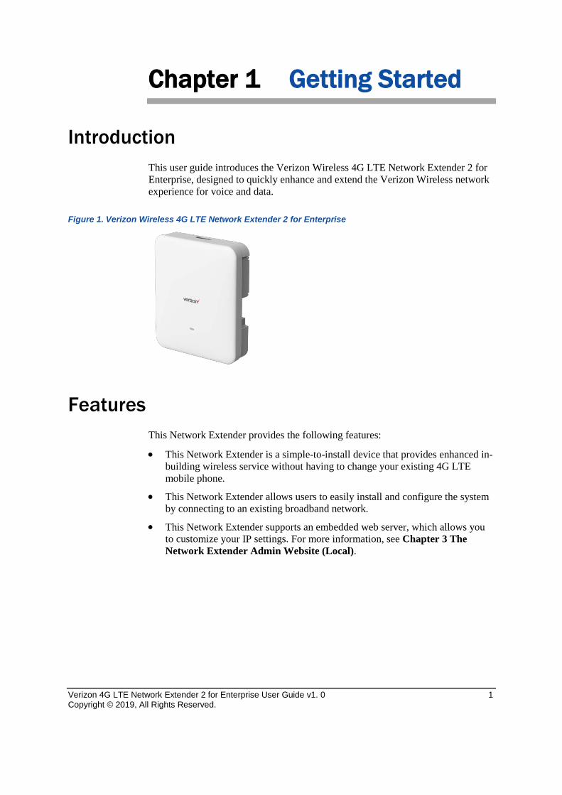
Introduction This user guide introduces the Verizon Wireless 4G LTE Network Extender 2 for Enterprise, designed to quickly enhance and extend the Verizon Wireless network experience for voice and data.
Figure 1. Verizon Wireless 4G LTE Network Extender 2 for Enterprise
Features This Network Extender provides the following features:
• This Network Extender is a simple-to-install device that provides enhanced in-building wireless service without having to change your existing 4G LTE mobile phone.
• This Network Extender allows users to easily install and configure the system by connecting to an existing broadband network.
• This Network Extender supports an embedded web server, which allows you to customize your IP settings. For more information, see Chapter 3 The Network Extender Admin Website (Local).
Chapter 1 Getting Started
Verizon 4G LTE Network Extender 2 for Enterprise User Guide v1.0 2 Copyright © 2019, All Rights Reserved.
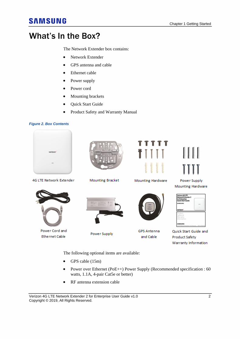
What’s In the Box? The Network Extender box contains:
• Network Extender
• GPS antenna and cable
• Ethernet cable
• Power supply
• Power cord
• Mounting brackets
• Quick Start Guide
• Product Safety and Warranty Manual
Figure 2. Box Contents
The following optional items are available:
• GPS cable (15m)
• Power over Ethernet (PoE++) Power Supply (Recommended specification : 60 watts, 1.1A, 4-pair Cat5e or better)
• RF antenna extension cable
Chapter 1 Getting Started
Verizon 4G LTE Network Extender 2 for Enterprise User Guide v1.0 3 Copyright © 2019, All Rights Reserved.
• 19-inch rack mount brackets
System Requirements • This device only supports Verizon Wireless 4G LTE mobile handsets with
Advanced Calling turned on, as shown in Chapter 2 (Device Setup) in the “Making a Call on Your Network Extender” section.
• Internet Access: This Network Extender must be connected to an available LAN port on a router or modem with always-on Internet connection with a recommended minimum bandwidth. o For 30 users or less, a bandwidth of 20 Mbps downlink and 10Mbps
uplink per unit is required to support an optimal data connection. o For 31 to 64 users, a bandwidth of 50Mbps downlink and 20Mbps uplink
or higher is recommended. For utilizing the full benefit of the LAA capabilities, internet backhaul download speeds of up to 300 Mbps may be needed.
• GPS signal: This Network Extender requires a continuous GPS signal from the provided GPS antenna. For the initial GPS fix, four strong GPS satellite signals must be available.
• Firewall modifications may be required to support the solution. Be sure to contact your IT administrator for the required changes. Please review the Server Addresses and Firewall Rules in chapter 4.
• The Network Extender supports IEEE 802.3ab Gigabit Ethernet Auto-Negotiation. Auto-Negotiation is a requirement of 802.3ab and may cause a speed and/or duplex mismatch if not fully enabled on the Network Extender switch/router port. Samsung recommends that Full auto-negotiation be enabled. If the Network Extender does not come into service as either 100/Full or 1000/Full, the recommendation is to configure statically as either 1000/Full (if capable) or 100/Full.
In the event that firewall changes are needed, please attempt to make these changes before calling into Customer Care. For more clarity on firewall settings, please see Chapter 4 (Configuring Your Device).
Chapter 1 Getting Started
Verizon 4G LTE Network Extender 2 for Enterprise User Guide v1.0 4 Copyright © 2019, All Rights Reserved.
Network Extender Basics This section will guide you through the basic features and functions of your Network Extender.
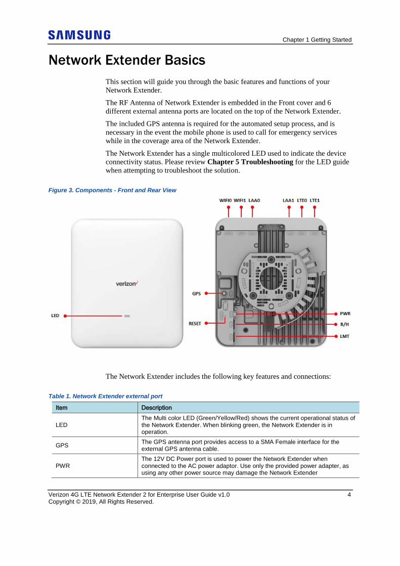
The RF Antenna of Network Extender is embedded in the Front cover and 6 different external antenna ports are located on the top of the Network Extender.
The included GPS antenna is required for the automated setup process, and is necessary in the event the mobile phone is used to call for emergency services while in the coverage area of the Network Extender.
The Network Extender has a single multicolored LED used to indicate the device connectivity status. Please review Chapter 5 Troubleshooting for the LED guide when attempting to troubleshoot the solution.
Figure 3. Components - Front and Rear View
The Network Extender includes the following key features and connections:
Table 1. Network Extender external port
Item Description
LED The Multi color LED (Green/Yellow/Red) shows the current operational status of the Network Extender. When blinking green, the Network Extender is in operation.
GPS The GPS antenna port provides access to a SMA Female interface for the external GPS antenna cable.
PWR The 12V DC Power port is used to power the Network Extender when connected to the AC power adaptor. Use only the provided power adapter, as using any other power source may damage the Network Extender
Chapter 1 Getting Started
Verizon 4G LTE Network Extender 2 for Enterprise User Guide v1.0 5 Copyright © 2019, All Rights Reserved.
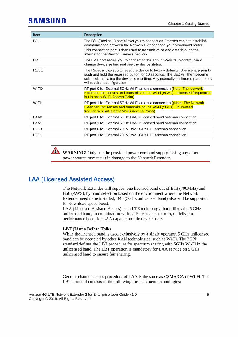
Item Description B/H The B/H (Backhaul) port allows you to connect an Ethernet cable to establish
communication between the Network Extender and your broadband router. This connection port is then used to transmit voice and data through the Internet to the Verizon wireless network.
LMT The LMT port allows you to connect to the Admin Website to control, view, change device setting and see the device status.
RESET The Reset allows you to reset the device to factory defaults. Use a sharp pen to push and hold the recessed button for 10 seconds. The LED will then become solid red, indicating the device is resetting. Any manually configured parameters will require reconfiguration
WIFI0 RF port 0 for External 5GHz Wi-Fi antenna connection (Note: The Network Extender unit senses and transmits on the Wi-Fi (5GHz) unlicensed frequencies but is not a Wi-Fi Access Point)
WIFI1 RF port 1 for External 5GHz Wi-Fi antenna connection ((Note: The Network Extender unit senses and transmits on the Wi-Fi (5GHz) unlicensed frequencies but is not a Wi-Fi Access Point))
LAA0 RF port 0 for External 5GHz LAA unlicensed band antenna connection LAA1 RF port 1 for External 5GHz LAA unlicensed band antenna connection LTE0 RF port 0 for External 700MHz/2.1GHz LTE antenna connection LTE1 RF port 1 for External 700MHz/2.1GHz LTE antenna connection
WARNING! Only use the provided power cord and supply. Using any other power source may result in damage to the Network Extender.
LAA (Licensed Assisted Access) The Network Extender will support one licensed band out of B13 (700MHz) and B66 (AWS), by band selection based on the environment where the Network Extender need to be installed; B46 (5GHz unlicensed band) also will be supported for download speed boost. LAA (Licensed Assisted Access) is an LTE technology that utilizes the 5 GHz unlicensed band, in combination with LTE licensed spectrum, to deliver a performance boost for LAA capable mobile device users. LBT (Listen Before Talk) While the licensed band is used exclusively by a single operator, 5 GHz unlicensed band can be occupied by other RAN technologies, such as Wi-Fi. The 3GPP standard defines the LBT procedure for spectrum sharing with 5GHz Wi-Fi in the unlicensed band. The LBT operation is mandatory for LAA service on 5 GHz unlicensed band to ensure fair sharing.
General channel access procedure of LAA is the same as CSMA/CA of Wi-Fi. The LBT protocol consists of the following three element technologies:
Chapter 1 Getting Started
Verizon 4G LTE Network Extender 2 for Enterprise User Guide v1.0 6 Copyright © 2019, All Rights Reserved.
• Carrier Sensing: The LAA Femto checks if other devices are using the wireless channel.
• Defer Duration: The LAA Femto waits for a certain time according to transmission priority.
• Random Backoff: The LAA Femto waits for random time to prevent collision between devices.
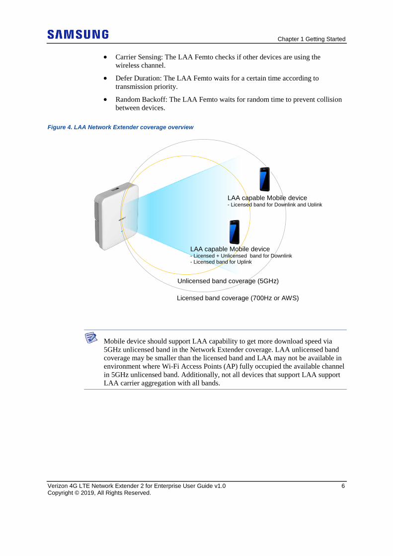
Figure 4. LAA Network Extender coverage overview
Mobile device should support LAA capability to get more download speed via 5GHz unlicensed band in the Network Extender coverage. LAA unlicensed band coverage may be smaller than the licensed band and LAA may not be available in environment where Wi-Fi Access Points (AP) fully occupied the available channel in 5GHz unlicensed band. Additionally, not all devices that support LAA support LAA carrier aggregation with all bands.
Licensed band coverage (700Hz or AWS)
Unlicensed band coverage (5GHz)
LAA capable Mobile device - Licensed + Unlicensed band for Downlink - Licensed band for Uplink
LAA capable Mobile device - Licensed band for Downlink and Uplink
Chapter 1 Getting Started
Verizon 4G LTE Network Extender 2 for Enterprise User Guide v1.0 7 Copyright © 2019, All Rights Reserved.
LAA FCC requirement The 5GHz unlicensed band (UNII-1 and UNII-3) of the Network Extender comply with FCC regulation CFR47 Part 15.407. The FCC defines the Max. EIRP limit of 36dBm for Indoor system.
WARNING! For external antenna use for 5GHz unlicensed band, a professional should install the Network Extender antenna, and the antenna gain must be less than 6dBi to ensure FCC compliance. Please refer to FCC requirement below.
FCC CFR 47 Part 15.407 (1) For the band 5.15 – 5.25GHz (i) For an outdoor access point operating in the band 5.15-5.25 GHz, the maximum conducted output power over the frequency band of operation shall not exceed 1 W provided the maximum antenna gain does not exceed 6dBi. In addition, the maximum power spectral density shall not exceed 17dBm in any 1 megahertz band. If transmitting antennas of directional gain greater than 6dBi are used, both the maximum conducted output power and the maximum power spectral density shall be reduced by the amount in dB that the directional gain of the antenna exceeds 6dBi. The maximum e.i.r.p. at any elevation angle above 30 degrees as measured from the horizon must not exceed 125mW (21dBm). (ii) For an indoor access point operating in the band 5.15-5.25 GHz, the maximum conducted output power over the frequency band of operation shall not exceed 1 W, provided the maximum antenna gain does not exceed 6dBi. In addition, the maximum power spectral density shall not exceed 17dBm in any 1 megahertz band. If transmitting antennas of directional gain greater than 6dBi are used, both the maximum conducted output power and the maximum power spectral density shall be reduced by the amount in dB that the directional gain of the antenna exceeds 6dBi. (2) For the band 5.725-5.85 GHz, the maximum conducted output power over the frequency band of operation shall not exceed 1 W. In addition, the maximum power spectral density shall not exceed 30dBm in any 500-kHz band. If transmitting antennas of directional gain greater than 6dBi are used, both the maximum conducted output power and the maximum power spectral density shall be reduced by the amount in dB that the directional gain of the antenna exceeds 6dBi. However, fixed point-to-point U-NII devices operating in this band may employ transmitting antennas with directional gain greater than 6dBi without any corresponding reduction in transmitter conducted power. Fixed, point-to-point operations exclude the use of point-to-multipoint systems, omnidirectional applications, and multiple collocated transmitters transmitting the same information. The operator of the U-NII device, or if the equipment is professionally installed, the installer is responsible for ensuring that systems employing high gain directional antennas are used exclusively for fixed, point-to-point operations.
Chapter 1 Getting Started
Verizon 4G LTE Network Extender 2 for Enterprise User Guide v1.0 8 Copyright © 2019, All Rights Reserved.
Network Extender Specifications
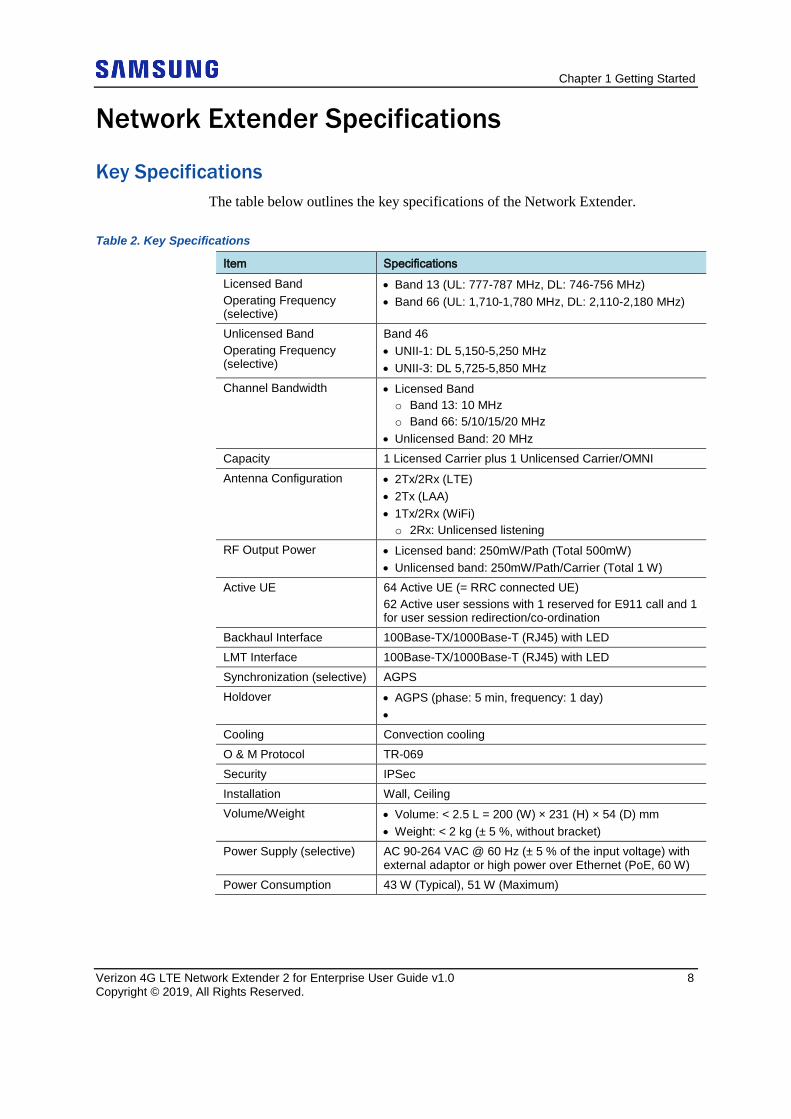
Key Specifications The table below outlines the key specifications of the Network Extender.
Table 2. Key Specifications
Item Specifications Licensed Band Operating Frequency (selective)
• Band 13 (UL: 777-787 MHz, DL: 746-756 MHz) • Band 66 (UL: 1,710-1,780 MHz, DL: 2,110-2,180 MHz)
Unlicensed Band Operating Frequency (selective)
Band 46 • UNII-1: DL 5,150-5,250 MHz • UNII-3: DL 5,725-5,850 MHz
Channel Bandwidth • Licensed Band o Band 13: 10 MHz o Band 66: 5/10/15/20 MHz
• Unlicensed Band: 20 MHz Capacity 1 Licensed Carrier plus 1 Unlicensed Carrier/OMNI Antenna Configuration • 2Tx/2Rx (LTE)
• 2Tx (LAA) • 1Tx/2Rx (WiFi) o 2Rx: Unlicensed listening
RF Output Power • Licensed band: 250mW/Path (Total 500mW) • Unlicensed band: 250mW/Path/Carrier (Total 1 W)
Active UE 64 Active UE (= RRC connected UE) 62 Active user sessions with 1 reserved for E911 call and 1 for user session redirection/co-ordination
Backhaul Interface 100Base-TX/1000Base-T (RJ45) with LED LMT Interface 100Base-TX/1000Base-T (RJ45) with LED Synchronization (selective) AGPS Holdover • AGPS (phase: 5 min, frequency: 1 day)
• Cooling Convection cooling O & M Protocol TR-069 Security IPSec Installation Wall, Ceiling Volume/Weight • Volume: < 2.5 L = 200 (W) × 231 (H) × 54 (D) mm
• Weight: < 2 kg (± 5 %, without bracket) Power Supply (selective) AC 90-264 VAC @ 60 Hz (± 5 % of the input voltage) with
external adaptor or high power over Ethernet (PoE, 60 W) Power Consumption 43 W (Typical), 51 W (Maximum)
Chapter 1 Getting Started
Verizon 4G LTE Network Extender 2 for Enterprise User Guide v1.0 9 Copyright © 2019, All Rights Reserved.
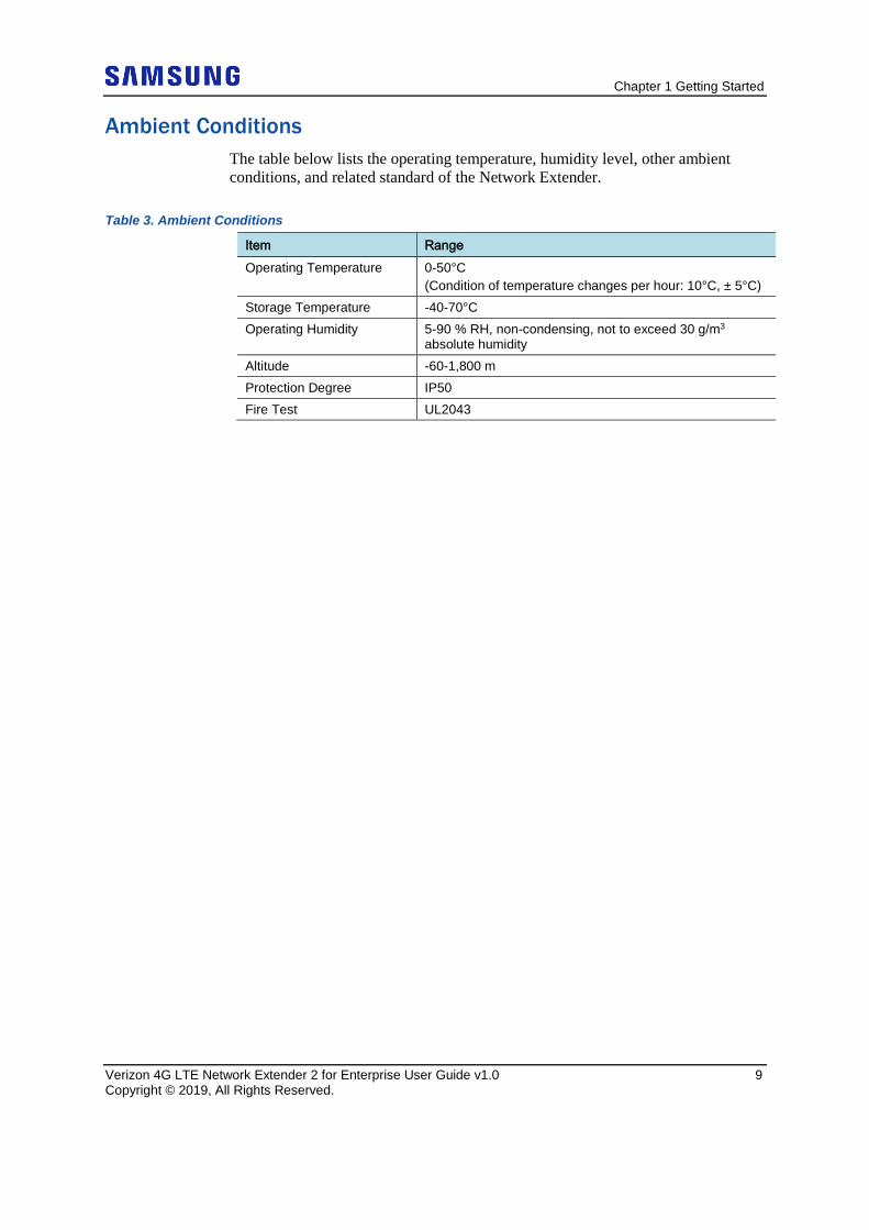
Ambient Conditions The table below lists the operating temperature, humidity level, other ambient conditions, and related standard of the Network Extender.
Table 3. Ambient Conditions
Item Range Operating Temperature 0-50°C
(Condition of temperature changes per hour: 10°C, ± 5°C) Storage Temperature -40-70°C Operating Humidity 5-90 % RH, non-condensing, not to exceed 30 g/m3
absolute humidity Altitude -60-1,800 m Protection Degree IP50 Fire Test UL2043
Verizon 4G LTE Network Extender 2 for Enterprise User Guide v1. 0 10 Copyright © 2019, All Rights Reserved.
Chapter 2 Network Extender Setup
Setup Procedure This section outlines the procedures needed to set up the Network Extender.
1 Confirm your package contains all components (see page 2, figure 2). 2 Review the Manual
Review the Product Safety and Warranty document and Quick Start Guide included in the package before installing the Network Extender.
3 Installation Place the Network Extender in the location where wireless 4G LTE service is desired. Ideally, it would be best to locate the Network Extender in a wall or ceiling that required the desired coverage area. This will typically result in the maximum coverage in one sided directions (unless there are unusual obstructions to consider). Please refer to the Installation section for details.
4 Cabling Please make sure the AC Power is off before installing Network Extender. Connect the provided GPS antenna cable to the GPS port of the Network Extender and plug the DC power cable of adaptor to the PWR port located at the rear of the Network Extender. Insert one end of the AC power cord into the power supply and then plug the other end into an available outlet. Ethernet cable needs to be connected to B/H port of the Network Extender. All cables must be carefully routed via cable tray for a wall mount to avoid any possible damage from the heat sink.
5 Power on Turn on the AC Power supply
Chapter 2 Network Extender Setup
Verizon 4G LTE Network Extender 2 for Enterprise User Guide v1.0 11 Copyright © 2019, All Rights Reserved.
Installation This section describes the procedures for a wall and ceiling mount.
Ensure that the Network Extender power is OFF when installing the system. Installing the system with the power ON may cause system damage or fatal human injury when connecting or disconnecting the cables.
To prevent the risk of electrical shock, do not wear accessories such as watches and rings.
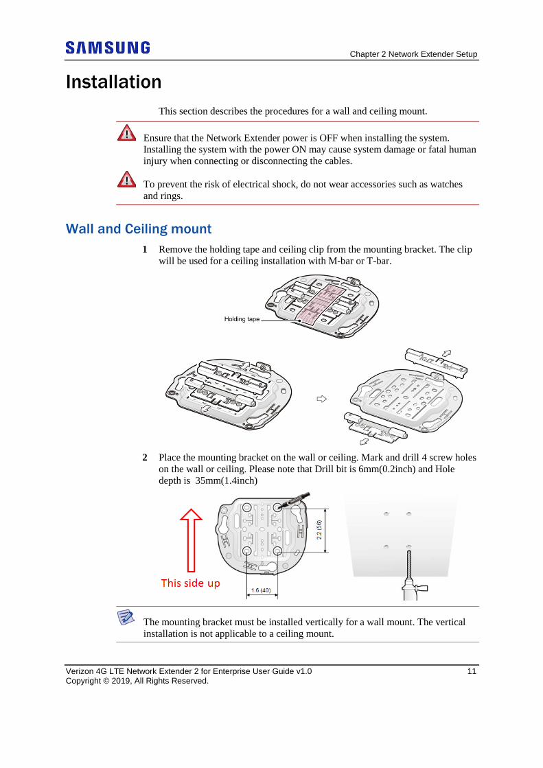
WalI and Ceiling mount 1 Remove the holding tape and ceiling clip from the mounting bracket. The clip
will be used for a ceiling installation with M-bar or T-bar.
2 Place the mounting bracket on the wall or ceiling. Mark and drill 4 screw holes
on the wall or ceiling. Please note that Drill bit is 6mm(0.2inch) and Hole depth is 35mm(1.4inch)
The mounting bracket must be installed vertically for a wall mount. The vertical installation is not applicable to a ceiling mount.
Chapter 2 Network Extender Setup
Verizon 4G LTE Network Extender 2 for Enterprise User Guide v1.0 12 Copyright © 2019, All Rights Reserved.
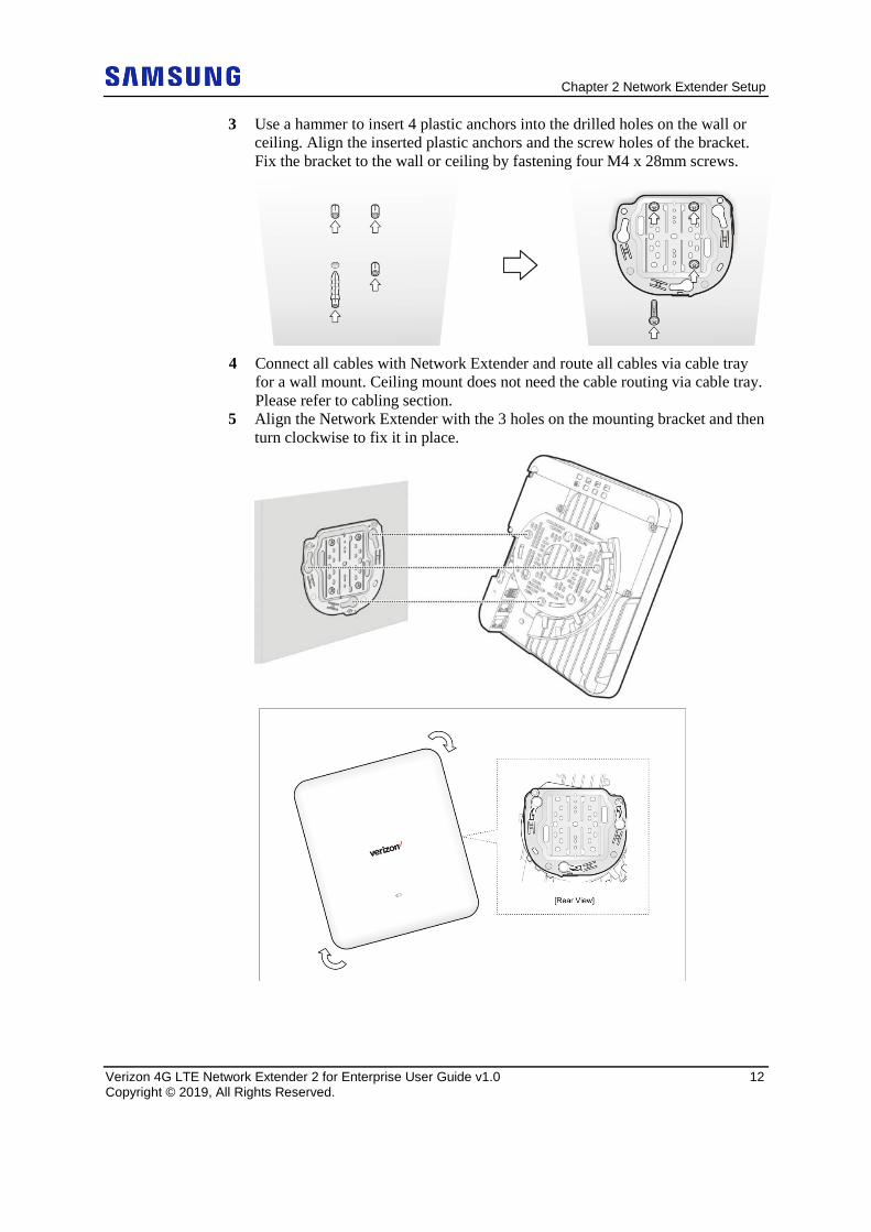
3 Use a hammer to insert 4 plastic anchors into the drilled holes on the wall or ceiling. Align the inserted plastic anchors and the screw holes of the bracket. Fix the bracket to the wall or ceiling by fastening four M4 x 28mm screws.
4 Connect all cables with Network Extender and route all cables via cable tray
for a wall mount. Ceiling mount does not need the cable routing via cable tray. Please refer to cabling section.
5 Align the Network Extender with the 3 holes on the mounting bracket and then turn clockwise to fix it in place.
Chapter 2 Network Extender Setup
Verizon 4G LTE Network Extender 2 for Enterprise User Guide v1.0 13 Copyright © 2019, All Rights Reserved.
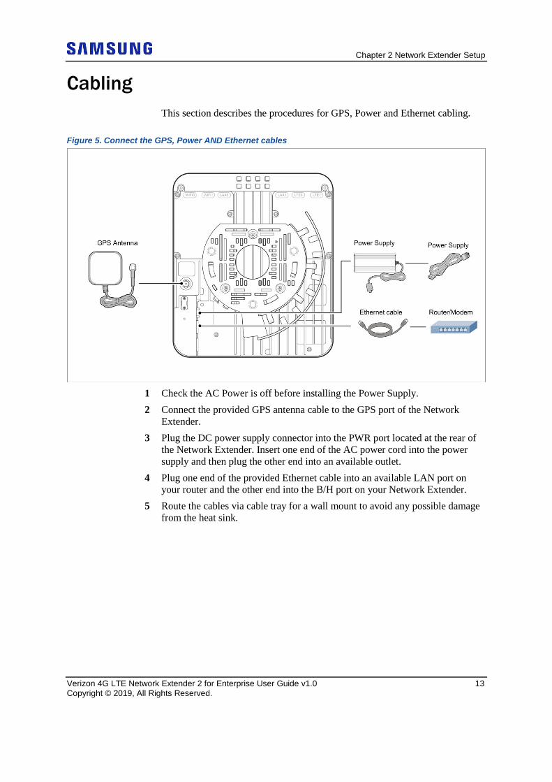
Cabling This section describes the procedures for GPS, Power and Ethernet cabling.
Figure 5. Connect the GPS, Power AND Ethernet cables
1 Check the AC Power is off before installing the Power Supply. 2 Connect the provided GPS antenna cable to the GPS port of the Network
Extender. 3 Plug the DC power supply connector into the PWR port located at the rear of
the Network Extender. Insert one end of the AC power cord into the power supply and then plug the other end into an available outlet.
4 Plug one end of the provided Ethernet cable into an available LAN port on your router and the other end into the B/H port on your Network Extender.
5 Route the cables via cable tray for a wall mount to avoid any possible damage from the heat sink.
Chapter 2 Network Extender Setup
Verizon 4G LTE Network Extender 2 for Enterprise User Guide v1.0 14 Copyright © 2019, All Rights Reserved.
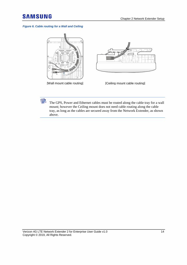
Figure 6. Cable routing for a Wall and Ceiling
The GPS, Power and Ethernet cables must be routed along the cable tray for a wall mount; however the Ceiling mount does not need cable routing along the cable tray, as long as the cables are secured away from the Network Extender, as shown above.
[Wall mount cable routing] [Ceiling mount cable routing]
Chapter 2 Network Extender Setup
Verizon 4G LTE Network Extender 2 for Enterprise User Guide v1.0 15 Copyright © 2019, All Rights Reserved.
Startup Sequence The following steps show the detailed Network Extender states during the startup sequence.
1 Powered-on and hardware initializing o The Network Extender State: The device has been powered on and the
system is performing hardware tests. o LED State: Solid red
The Network Extender is under an autonomous hardware test cycle. It is not possible to load or run any software, including the user Admin Website Page.
2 Hardware test completed and software loaded (“Boot Complete”)
Chapter 2 Network Extender Setup
Verizon 4G LTE Network Extender 2 for Enterprise User Guide v1.0 16 Copyright © 2019, All Rights Reserved.
o The Network Extender State: The device has completed hardware initialization and loaded all software.
o LED State: Solid yellow o Admin Website State: The software is loaded. The Admin Website is
accessible.
The device has completed its autonomous hardware tests and loaded all software. It will start the process of connecting to Verizon’s network and coming into service. See the Admin Website chapter for information on how to log into the Network Extender Admin Webpage.
3 Acquired IPv4/IPv6 address ("Acquired an IP address")
o The Network Extender State: The device is running its software and has started to connect to the Verizon network. The first step is to acquire a local IPv4/IPv6 address.
o LED State : Single blinking yellow (0.5 sec. on, 3.0 sec. off) o Admin Website State: The Admin Website is accessible.
The device has loaded software and has started to acquire a local IPv4/IPv6 address from the local DHCP server.
4 Conducting DNS lookups ("Identifying the Initial Network")
o The Network Extender State: The device has acquired a local IPv4/IPv6 address from local DHCP. The next step is to conduct DNS lookups for the public FQDNs provisioned at the factory.
o LED State: Single blinking yellow (0.5 sec. on, 3.0 sec off) o Admin Website State: The Admin Website is accessible.
The Network Extender needs to resolve the FQDNs for A-GPS, and initial SeGW from the public DNS server.
5 Attempting to reach the Initial SeGW (“Attempting to reach Initial
network”) o The Network Extender State: The device has conducted DNS lookups for
the public FQDNs provisioned at the factory and is trying to contact the initial SeGW.
o LED State : Single blinking yellow (0.5sec. on, 3.0 sec off) o Admin Website State: The Admin Website is accessible.
This status details that the Network Extender has attempted to communicate with the SeGW.
Chapter 2 Network Extender Setup
Verizon 4G LTE Network Extender 2 for Enterprise User Guide v1.0 17 Copyright © 2019, All Rights Reserved.
6 Successfully reached the Initial SeGW (“Successfully reached the Initial
network”) o The Network Extender State: The device has contacted the initial SeGW
successfully. o LED State : Single blinking yellow (o.5 sec. on, 3.0 sec. off) o Admin Website State: The Admin Website is accessible.
Status details that the device can communicate with the SeGW and IPSec tunnel are not established at this point.
7 VPN setup to Initial SeGW completed ("Authentication to Initial Network
completed successfully") o The Network Extender State: The device has set up a VPN tunnel with the
initial SeGW. o LED State: Single blinking yellow (0.5 sec. on, 3.0 sec off) o Admin Website State: The Admin Website is accessible.
This confirms that the device has set up a VPN connection with Verizon’s network.
8 Authentication failure during IPSec tunnel setup to Initial SeGW
("Authentication failure to Initial Network. Unit is not provisioned. Please contact Verizon Wireless Customer Care for further assistance") o The Network Extender State: The device has failed to set up a VPN tunnel
with the initial SeGW with an explicit “Authentication Failure.” o LED State: Double blinking red (0.5 sec. on, 0.5 sec. off, 0.5 sec. on, 3.0
sec. off) o Admin Website State: The Admin Website is accessible.
This details that the device been notified it failed authentication with the Verizon Authentication server.
9 GPS acquisition in progress ("Waiting for GPS position fix")
Chapter 2 Network Extender Setup
Verizon 4G LTE Network Extender 2 for Enterprise User Guide v1.0 18 Copyright © 2019, All Rights Reserved.
o The Network Extender State: The device has set up a VPN tunnel with the initial SeGW and is awaiting a GPS fix before progressing.
o LED State: Triple blinking yellow (0.5 sec. on, 0.5 sec. off, 0.5sec. on, 0.5sec. off, 0.5 sec. on, 3.0 sec. off)
o Admin Website State: The Admin Website is accessible.
Until a GPS fix is provided, the device will not be able to continue and receive configuration information.
10 Connection with the management system ("Connecting to Initial Management Server") o The Network Extender State: The device acquired location information
and is connecting with the FeMS. o LED State: Quadruple blinking yellow (0.5 sec. on, 0.5 sec. off, 0.5 sec.
on, 0.5 sec. off, 0.5 sec on, 0.5 sec. off, 0.5 sec. on, 3.0 sec. off) o Admin Website State: The Admin Website is accessible.
The device will be allocated a serving FeMS and possibly an alternate serving SeGW based on its location. It may re-establish IPSec to the new SeGW at this point if required. If not, it will contact the FeMS and request configuration information.
11 Software download in progress
o The Network Extender State: The device is assigned a FeMS and has been instructed to download new software.
o LED State: Quadruple blinking yellow (0.5 sec. on, 0.5 sec. off, 0.5 sec. on, 0.5 sec. off, 0.5 sec on, 0.5 sec. off, 0.5 sec. on, 3.5 sec. off)
o Admin Website State: The Admin Website is accessible.
The device will download the newest software and reboot. The process will start from the first steps again, but the GPS acquisition will occur much faster.
12 Configuration download in progress
Chapter 2 Network Extender Setup
Verizon 4G LTE Network Extender 2 for Enterprise User Guide v1.0 19 Copyright © 2019, All Rights Reserved.
o The Network Extender State: The device is communicating with the Verizon management system (FeMS) and may have received new software. It will need to complete the “Over the Air Receiver” before receiving additional configuration parameters.
o LED State: Quadruple blinking yellow (0.5 sec. on, 0.5 sec. off, 0.5 sec. on, 0.5 sec. off, 0.5 sec on, 0.5 sec. off, 0.5 sec. on, 3.0 sec. off)
o Admin Website State: The Admin Website is accessible.
During the OTAR process, if no adjacent neighbor Network Extenders or Macro cells are detected, the Verizon Management system (FeMS) will then provide the configuration solely based on the GPS location.
13 Operational status
o The Network Extender State: The device is in normal in-service operation and has completed all steps.
o LED State: Fast blinking green (0.25 sec. on/0.25 sec. off) o Admin Website State: The Admin Website is accessible.
If the LED state is alternate blinking Red-Green instead of fast blinking green, this means an alarm condition has occurred. In this case, please refer to the Troubleshooting chapter for more information on alarm codes.
Chapter 2 Network Extender Setup
Verizon 4G LTE Network Extender 2 for Enterprise User Guide v1.0 20 Copyright © 2019, All Rights Reserved.
Making a Call Once the Network Extender is in service, your phone must be within 50 feet of the Network Extender to connect to the Network Extender and make calls.
To verify your Verizon phones are connected to the Network Extender:
1 Make sure your Verizon Wireless 4G LTE mobile phone has the Advanced Calling feature turned on.
14 Dial #48 from your mobile phone and listen for the following confirmation: “You are under 4G LTE Network Extender coverage …”
15 Some phones may show a home icon when connected to the Network Extender.
The Network Extender’s coverage depends on environmental factors, such as physical structures and the strength of external cell towers.
To turn on Advanced Calling on your 4G LTE Verizon Wireless phone, follow the steps below for your device’s operating system:
• Android™: Go to Settings > Advanced Calling and turn ON service.
On some devices, it may be found in Wireless Calling, HD Voice or VoLTE call.
• Apple® iOS: Go to Settings > Cellular > Cellular Data Options > Enable LTE > Voice & Data. Additionally, on the “My Verizon” Mobile App, enable Advance Calling feature for your phones.
• Windows®: Go to Settings > Cellular+SIM > SIM settings and turn ON Advanced Calling.
Chapter 2 Network Extender Setup
Verizon 4G LTE Network Extender 2 for Enterprise User Guide v1.0 21 Copyright © 2019, All Rights Reserved.
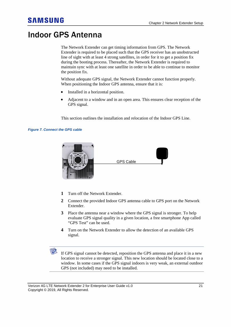
Indoor GPS Antenna The Network Extender can get timing information from GPS. The Network Extender is required to be placed such that the GPS receiver has an unobstructed line of sight with at least 4 strong satellites, in order for it to get a position fix during the booting process. Thereafter, the Network Extender is required to maintain sync with at least one satellite in order to be able to continue to monitor the position fix.
Without adequate GPS signal, the Network Extender cannot function properly. When positioning the Indoor GPS antenna, ensure that it is:
• Installed in a horizontal position.
• Adjacent to a window and in an open area. This ensures clear reception of the GPS signal.
This section outlines the installation and relocation of the Indoor GPS Line.
Figure 7. Connect the GPS cable
1 Turn off the Network Extender.
2 Connect the provided Indoor GPS antenna cable to GPS port on the Network Extender.
3 Place the antenna near a window where the GPS signal is stronger. To help evaluate GPS signal quality in a given location, a free smartphone App called “GPS Test” can be used.
4 Turn on the Network Extender to allow the detection of an available GPS signal.
If GPS signal cannot be detected, reposition the GPS antenna and place it in a new location to receive a stronger signal. This new location should be located close to a window. In some cases if the GPS signal indoors is very weak, an external outdoor GPS (not included) may need to be installed.
GPS Cable
Chapter 2 Network Extender Setup
Verizon 4G LTE Network Extender 2 for Enterprise User Guide v1.0 22 Copyright © 2019, All Rights Reserved.
A GPS signal is required for proper operation and E911 service. If a GPS signal is not acquired after 30 to 60 minutes, please see Chapter 4 Configuring Your Device.
To see the status of the GPS acquisition, use the Admin website (Local) as shown in Chapter 3, The Network Extender Admin Website (Local).
Chapter 2 Network Extender Setup
Verizon 4G LTE Network Extender 2 for Enterprise User Guide v1.0 23 Copyright © 2019, All Rights Reserved.
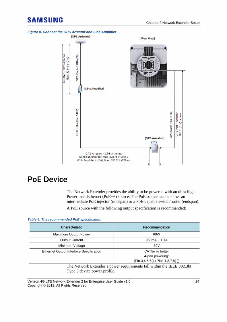
Outdoor GPS Antenna If your Network Extender cannot receive a Global Positioning System (GPS) signal by using the supplied Indoor GPS antenna, it may be necessary to improve the reception by installing and then positioning the outdoor GPS antenna. This section outlines the installation of outdoor GPS antenna.
An outdoor GPS antenna system configuration, which typically requires longer cable runs is shown below.
• If needed, a Line amplifier can be installed within 32.8 ft. (10 m) from the GPS antenna. As an alternative, a high-gain GPS antenna can be installed instead of Line Amplifiers to help overcome cable losses. The Network Extender uses standard GPS cables and accessories, which may be purchased from any GPS equipment reseller. A receive signal strength of -152dBm is sufficient at the GPS port for the Network Extender.
For outdoor GPS antenna installation details, please refer to Appendix A (Outdoor GPS Antenna Installation) of this guide.
Chapter 2 Network Extender Setup
Verizon 4G LTE Network Extender 2 for Enterprise User Guide v1.0 24 Copyright © 2019, All Rights Reserved.
Figure 8. Connect the GPS Arrestor and Line Amplifier
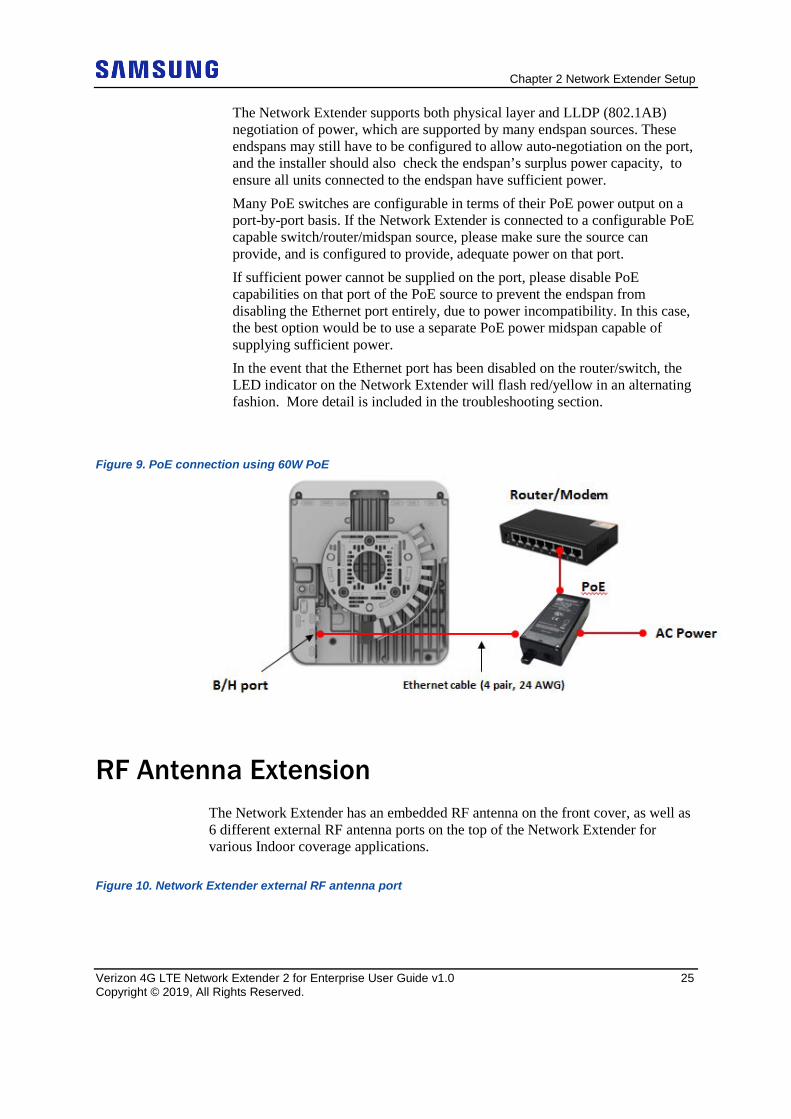
PoE Device The Network Extender provides the ability to be powered with an ultra-high Power over Ethernet (PoE++) source. The PoE source can be either an intermediate PoE injector (midspan) or a PoE-capable switch/router (endspan). A PoE source with the following output specification is recommended:
Table 4. The recommended PoE specification
Characteristic Recommendation
Maximum Output Power 60W Output Current 960mA ~ 1.1A
Minimum Voltage 50V Ethernet Output Interface Specification CAT5e or better
4-pair powering: (Pin 3,4,5,6(+) Pins 1,2,7,8(-))
The Network Extender’s power requirements fall within the IEEE 802.3bt Type 3 device power profile.
Chapter 2 Network Extender Setup
Verizon 4G LTE Network Extender 2 for Enterprise User Guide v1.0 25 Copyright © 2019, All Rights Reserved.
The Network Extender supports both physical layer and LLDP (802.1AB) negotiation of power, which are supported by many endspan sources. These endspans may still have to be configured to allow auto-negotiation on the port, and the installer should also check the endspan’s surplus power capacity, to ensure all units connected to the endspan have sufficient power. Many PoE switches are configurable in terms of their PoE power output on a port-by-port basis. If the Network Extender is connected to a configurable PoE capable switch/router/midspan source, please make sure the source can provide, and is configured to provide, adequate power on that port. If sufficient power cannot be supplied on the port, please disable PoE capabilities on that port of the PoE source to prevent the endspan from disabling the Ethernet port entirely, due to power incompatibility. In this case, the best option would be to use a separate PoE power midspan capable of supplying sufficient power. In the event that the Ethernet port has been disabled on the router/switch, the LED indicator on the Network Extender will flash red/yellow in an alternating fashion. More detail is included in the troubleshooting section.
Figure 9. PoE connection using 60W PoE
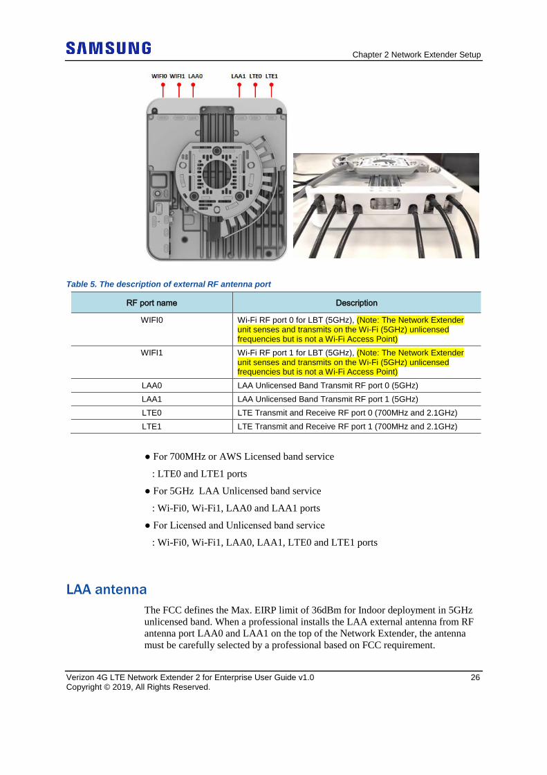
RF Antenna Extension The Network Extender has an embedded RF antenna on the front cover, as well as 6 different external RF antenna ports on the top of the Network Extender for various Indoor coverage applications.
Figure 10. Network Extender external RF antenna port
Chapter 2 Network Extender Setup
Verizon 4G LTE Network Extender 2 for Enterprise User Guide v1.0 26 Copyright © 2019, All Rights Reserved.
Table 5. The description of external RF antenna port
RF port name Description
WIFI0 Wi-Fi RF port 0 for LBT (5GHz), (Note: The Network Extender unit senses and transmits on the Wi-Fi (5GHz) unlicensed frequencies but is not a Wi-Fi Access Point)
WIFI1 Wi-Fi RF port 1 for LBT (5GHz), (Note: The Network Extender unit senses and transmits on the Wi-Fi (5GHz) unlicensed frequencies but is not a Wi-Fi Access Point)
LAA0 LAA Unlicensed Band Transmit RF port 0 (5GHz) LAA1 LAA Unlicensed Band Transmit RF port 1 (5GHz) LTE0 LTE Transmit and Receive RF port 0 (700MHz and 2.1GHz) LTE1 LTE Transmit and Receive RF port 1 (700MHz and 2.1GHz)
● For 700MHz or AWS Licensed band service
: LTE0 and LTE1 ports
● For 5GHz LAA Unlicensed band service
: Wi-Fi0, Wi-Fi1, LAA0 and LAA1 ports
● For Licensed and Unlicensed band service
: Wi-Fi0, Wi-Fi1, LAA0, LAA1, LTE0 and LTE1 ports
LAA antenna The FCC defines the Max. EIRP limit of 36dBm for Indoor deployment in 5GHz unlicensed band. When a professional installs the LAA external antenna from RF antenna port LAA0 and LAA1 on the top of the Network Extender, the antenna must be carefully selected by a professional based on FCC requirement.
Chapter 2 Network Extender Setup
Verizon 4G LTE Network Extender 2 for Enterprise User Guide v1.0 27 Copyright © 2019, All Rights Reserved.
Please refer to Chapter 1 (LAA FCC requirement) in the Getting Started section.
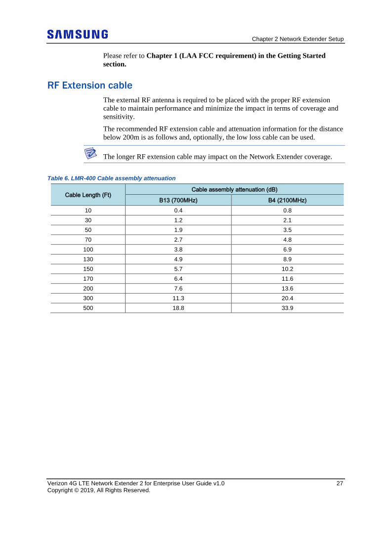
RF Extension cable The external RF antenna is required to be placed with the proper RF extension cable to maintain performance and minimize the impact in terms of coverage and sensitivity.
The recommended RF extension cable and attenuation information for the distance below 200m is as follows and, optionally, the low loss cable can be used.
The longer RF extension cable may impact on the Network Extender coverage.
Table 6. LMR-400 Cable assembly attenuation
Cable Length (Ft) Cable assembly attenuation (dB)
B13 (700MHz) B4 (2100MHz) 10 0.4 0.8 30 1.2 2.1 50 1.9 3.5 70 2.7 4.8
100 3.8 6.9 130 4.9 8.9 150 5.7 10.2 170 6.4 11.6 200 7.6 13.6 300 11.3 20.4 500 18.8 33.9
Chapter 2 Network Extender Setup
Verizon 4G LTE Network Extender 2 for Enterprise User Guide v1.0 28 Copyright © 2019, All Rights Reserved.
Chapter 2 Network Extender Setup
Verizon 4G LTE Network Extender 2 for Enterprise User Guide v1.0 29 Copyright © 2019, All Rights Reserved.
Making a Call Once the Network Extender is in service, your phone must be within 50 feet of the Network Extender to connect to the Network Extender and make calls.
To verify your Verizon phones are connected to the Network Extender:
• Make sure your Verizon Wireless 4G LTE mobile phone has the Advanced Calling feature turned on.
• Dial #48 from your mobile phone and listen for the following confirmation: “You are under 4G LTE Network Extender coverage …”
• Some phones may show a home icon when connected to the Network Extender.
The Network Extender’s coverage depends on environmental factors, such as physical structures and the strength of external cell towers.
To turn on Advanced Calling on your 4G LTE Verizon Wireless phone, follow the steps below for your device’s operating system:
• Android™: Go to Settings > Advanced Calling and turn ON service.
On some devices, it may be found in Wireless Calling, HD Voice or VoLTE call.
• Apple® iOS: Go to Settings > Cellular > Cellular Data Options > Enable LTE > Voice & Data. Additionally, on the “My Verizon” Mobile App, enable Advance Calling feature for your phones.
• Windows®: Go to Settings > Cellular+SIM > SIM settings and turn ON Advanced Calling.
Verizon 4G LTE Network Extender 2 for Enterprise User Guide v1. 0 30 Copyright © 2019, All Rights Reserved.
Chapter 3 The Network Extender Admin Website (Local)
This section contains detailed information regarding the Network Extender Admin Website (Local) where you can see the device status and make changes to settings.
PC Requirements To access the Admin Website, a PC should satisfy the following conditions:
• IE (Internet Explorer): 9, 10, 11
• Chrome: 35.0.1916.153 or higher version
• FireFox: 30.0 or higher version
• Safari: 7.0.2 or higher version
• Internet connection
Admin Website Access There are two ways to access the Network Extender Admin Website. One is by using LMT port on the back side of the Network Extender and the other is to directly connect to Network Extender by using the Network Extender IP address, in case your computer, is connected to the same network as the Network Extender.
LMT port In order to connect to the Network Extender, you will need to change your TCP/IPv4 settings to connect directly to the LMT port from your laptop, using an Ethernet cable.
To access settings and manage the Network Extender, sign in to the web interface by following these steps:
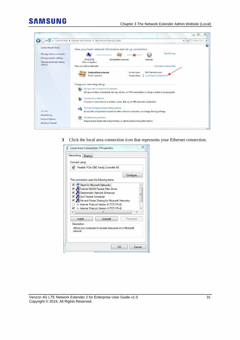
1 In Windows, click Control Panel on the Start menu. 2 Click Network and Sharing Center.
Chapter 3 The Network Extender Admin Website (Local)
Verizon 4G LTE Network Extender 2 for Enterprise User Guide v1.0 31 Copyright © 2019, All Rights Reserved.
3 Click the local area connection icon that represents your Ethernet connection.
Chapter 3 The Network Extender Admin Website (Local)
Verizon 4G LTE Network Extender 2 for Enterprise User Guide v1.0 32 Copyright © 2019, All Rights Reserved.
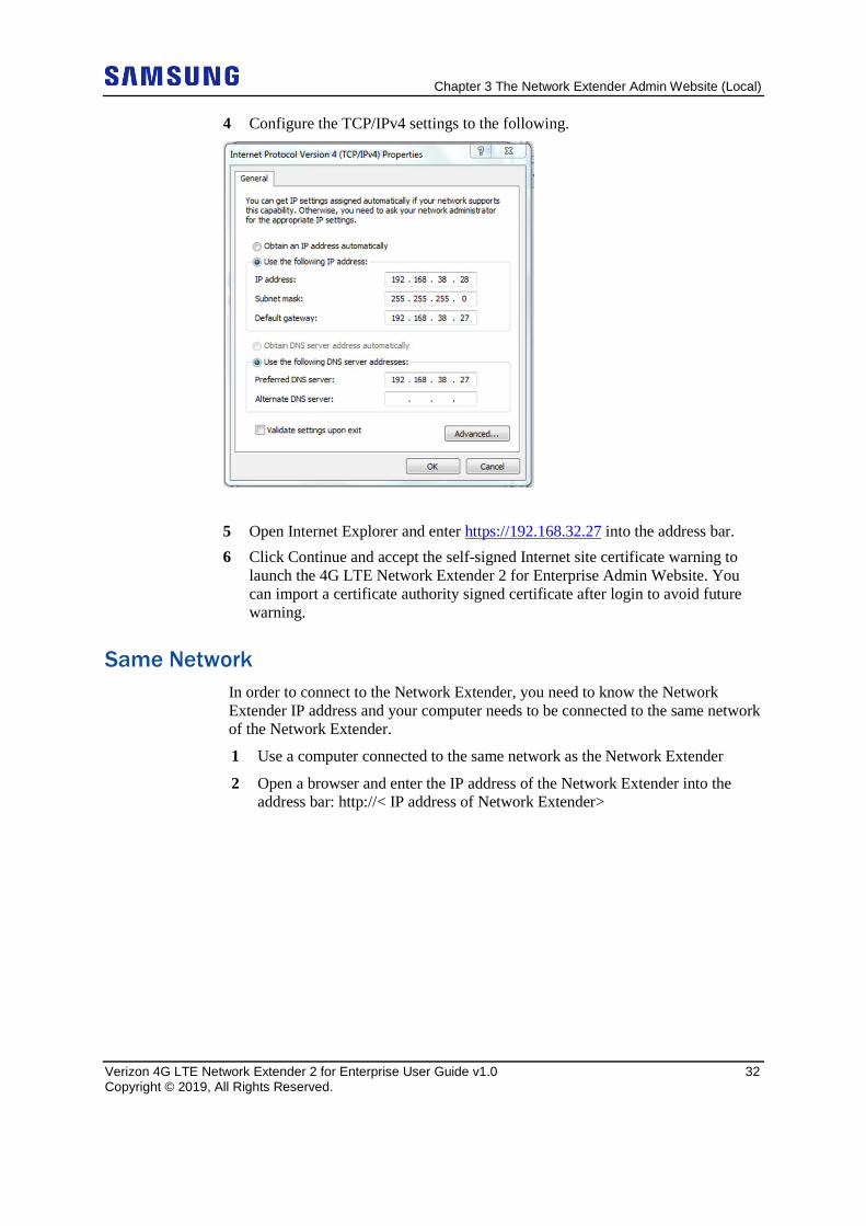
4 Configure the TCP/IPv4 settings to the following.
5 Open Internet Explorer and enter https://192.168.32.27 into the address bar. 6 Click Continue and accept the self-signed Internet site certificate warning to
launch the 4G LTE Network Extender 2 for Enterprise Admin Website. You can import a certificate authority signed certificate after login to avoid future warning.
Same Network In order to connect to the Network Extender, you need to know the Network Extender IP address and your computer needs to be connected to the same network of the Network Extender.
1 Use a computer connected to the same network as the Network Extender
2 Open a browser and enter the IP address of the Network Extender into the address bar: http://< IP address of Network Extender>
Chapter 3 The Network Extender Admin Website (Local)
Verizon 4G LTE Network Extender 2 for Enterprise User Guide v1.0 33 Copyright © 2019, All Rights Reserved.
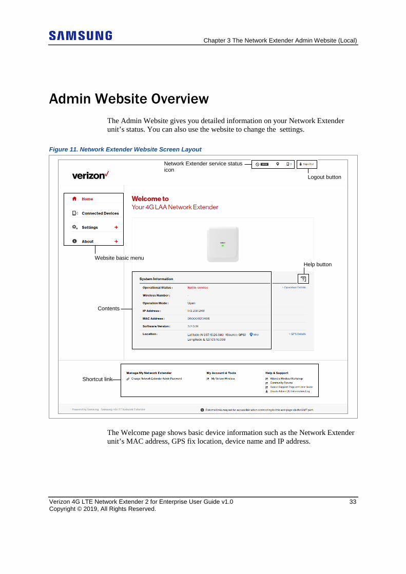
Admin Website Overview The Admin Website gives you detailed information on your Network Extender unit’s status. You can also use the website to change the settings.
Figure 11. Network Extender Website Screen Layout
The Welcome page shows basic device information such as the Network Extender unit’s MAC address, GPS fix location, device name and IP address.
Network Extender service status icon
Logout button
Website basic menu
Contents
Help button
Shortcut link
Chapter 3 The Network Extender Admin Website (Local)
Verizon 4G LTE Network Extender 2 for Enterprise User Guide v1.0 34 Copyright © 2019, All Rights Reserved.
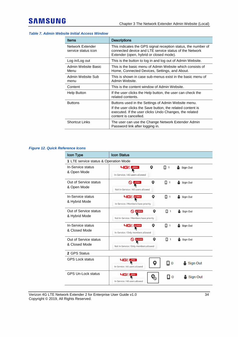
Table 7. Admin Website Initial Access Window
Items Descriptions Network Extender service status icon
This indicates the GPS signal reception status, the number of connected device and LTE service status of the Network Extender (open, hybrid or closed mode).
Log in/Log out This is the button to log in and log out of Admin Website. Admin Website Basic Menu
This is the basic menu of Admin Website which consists of Home, Connected Devices, Settings, and About.
Admin Website Sub menu
This is shown in case sub-menus exist in the basic menu of Admin Website.
Content This is the content window of Admin Website. Help Button If the user clicks the Help button, the user can check the
related contents. Buttons Buttons used in the Settings of Admin Website menu.
If the user clicks the Save button, the related content is executed. If the user clicks Undo Changes, the related content is cancelled.
Shortcut Links The user can use the Change Network Extender Admin Password link after logging in.
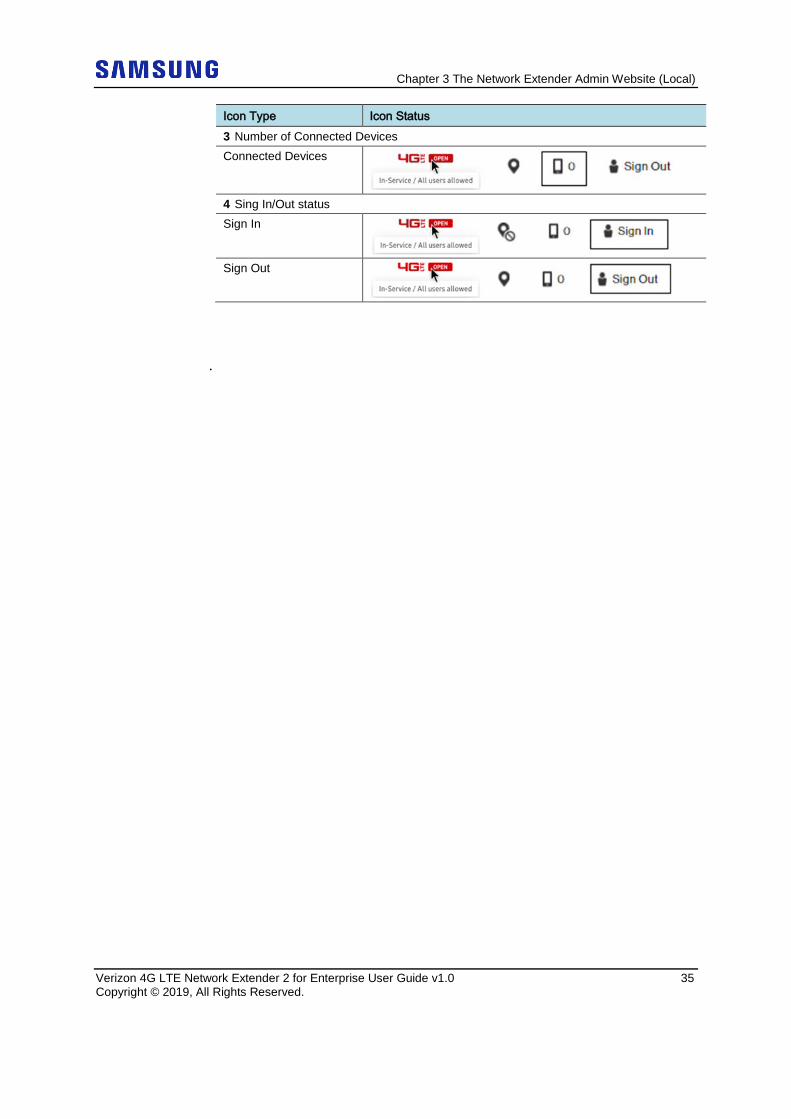
Figure 12. Quick Reference Icons
Icon Type Icon Status 1 LTE service status & Operation Mode In-Service status & Open Mode
Out of Service status & Open Mode
In-Service status & Hybrid Mode
Out of Service status & Hybrid Mode
In-Service status & Closed Mode
Out of Service status & Closed Mode
2 GPS Status GPS Lock status
GPS Un-Lock status
Chapter 3 The Network Extender Admin Website (Local)
Verizon 4G LTE Network Extender 2 for Enterprise User Guide v1.0 35 Copyright © 2019, All Rights Reserved.
Icon Type Icon Status 3 Number of Connected Devices Connected Devices
4 Sing In/Out status Sign In
Sign Out
.
Chapter 3 The Network Extender Admin Website (Local)
Verizon 4G LTE Network Extender 2 for Enterprise User Guide v1.0 36 Copyright © 2019, All Rights Reserved.
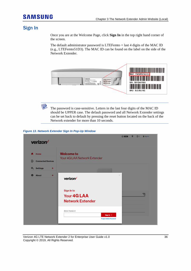
Sign In Once you are at the Welcome Page, click Sign In in the top right hand corner of the screen.
The default administrator password is LTEFemto + last 4 digits of the MAC ID (e.g., LTEFemto51D3). The MAC ID can be found on the label on the side of the Network Extender.
The password is case-sensitive. Letters in the last four digits of the MAC ID should be UPPER case. The default password and all Network Extender settings can be set back to default by pressing the reset button located on the back of the Network extender for more than 10 seconds.
Figure 13. Network Extender Sign In Pop-Up Window
Chapter 3 The Network Extender Admin Website (Local)
Verizon 4G LTE Network Extender 2 for Enterprise User Guide v1.0 37 Copyright © 2019, All Rights Reserved.
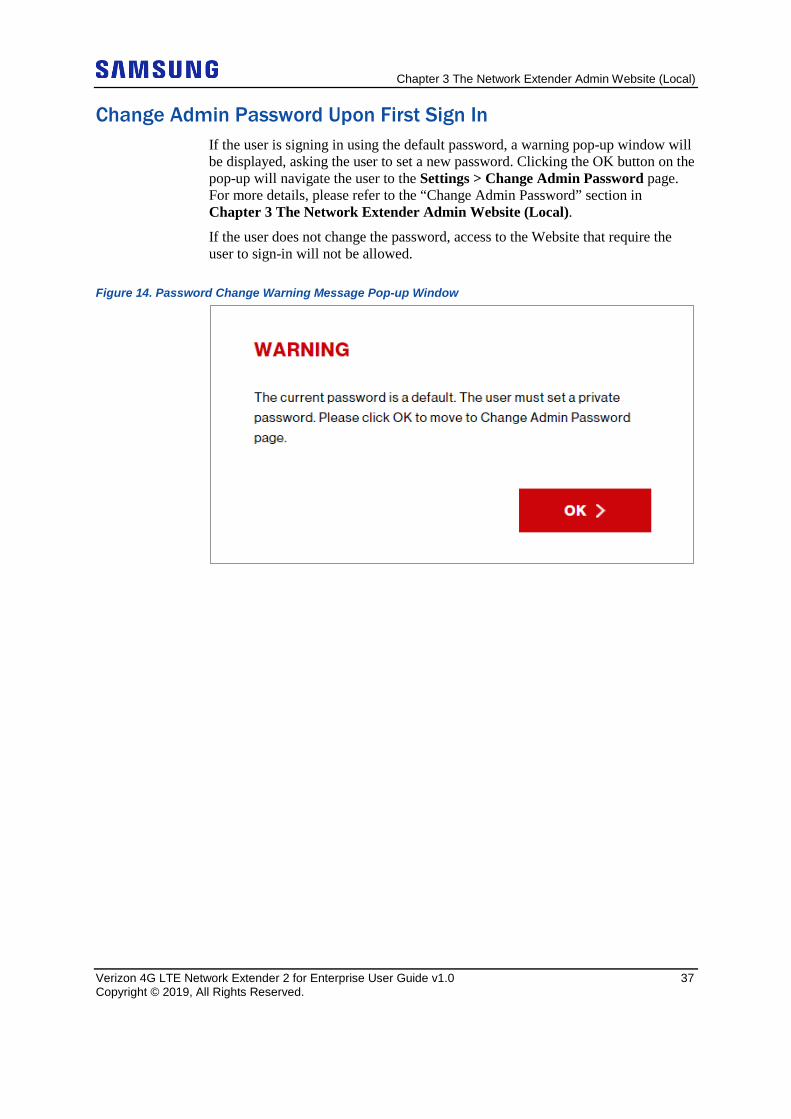
Change Admin Password Upon First Sign In If the user is signing in using the default password, a warning pop-up window will be displayed, asking the user to set a new password. Clicking the OK button on the pop-up will navigate the user to the Settings > Change Admin Password page. For more details, please refer to the “Change Admin Password” section in Chapter 3 The Network Extender Admin Website (Local).
If the user does not change the password, access to the Website that require the user to sign-in will not be allowed.
Figure 14. Password Change Warning Message Pop-up Window
Chapter 3 The Network Extender Admin Website (Local)
Verizon 4G LTE Network Extender 2 for Enterprise User Guide v1.0 38 Copyright © 2019, All Rights Reserved.
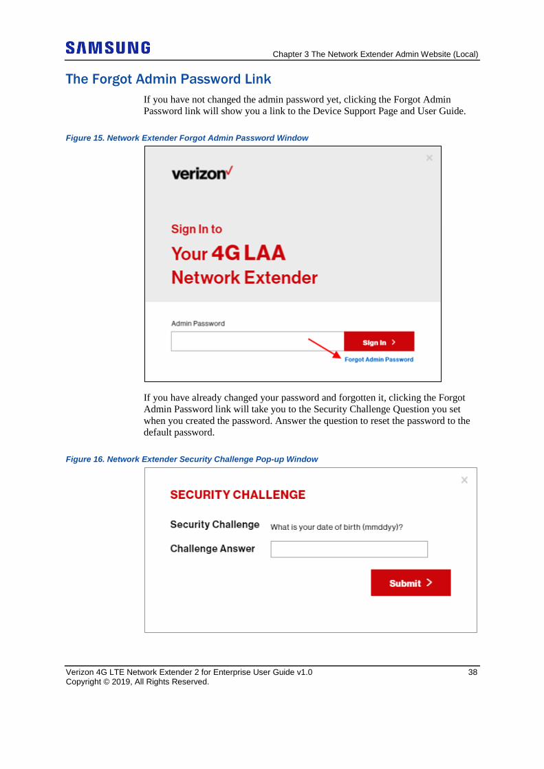
The Forgot Admin Password Link If you have not changed the admin password yet, clicking the Forgot Admin Password link will show you a link to the Device Support Page and User Guide.
Figure 15. Network Extender Forgot Admin Password Window
If you have already changed your password and forgotten it, clicking the Forgot Admin Password link will take you to the Security Challenge Question you set when you created the password. Answer the question to reset the password to the default password.
Figure 16. Network Extender Security Challenge Pop-up Window
Chapter 3 The Network Extender Admin Website (Local)
Verizon 4G LTE Network Extender 2 for Enterprise User Guide v1.0 39 Copyright © 2019, All Rights Reserved.
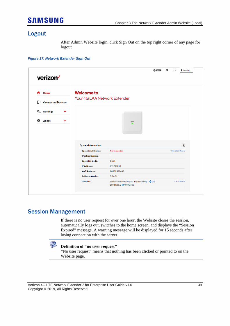
Logout After Admin Website login, click Sign Out on the top right corner of any page for logout
Figure 17. Network Extender Sign Out
Session Management If there is no user request for over one hour, the Website closes the session, automatically logs out, switches to the home screen, and displays the “Session Expired” message. A warning message will be displayed for 15 seconds after losing connection with the server.
Definition of “no user request” “No user request” means that nothing has been clicked or pointed to on the Website page.
Chapter 3 The Network Extender Admin Website (Local)
Verizon 4G LTE Network Extender 2 for Enterprise User Guide v1.0 40 Copyright © 2019, All Rights Reserved.
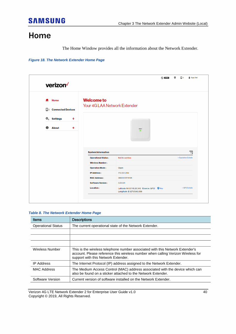
Home The Home Window provides all the information about the Network Extender.
Figure 18. The Network Extender Home Page
Table 8. The Network Extender Home Page
Items Descriptions Operational Status The current operational state of the Network Extender. Wireless Number This is the wireless telephone number associated with this Network Extender's
account. Please reference this wireless number when calling Verizon Wireless for support with this Network Extender.
IP Address The Internet Protocol (IP) address assigned to the Network Extender. MAC Address The Medium Access Control (MAC) address associated with the device which can
also be found on a sticker attached to the Network Extender. Software Version Current version of software installed on the Network Extender.
Chapter 3 The Network Extender Admin Website (Local)
Verizon 4G LTE Network Extender 2 for Enterprise User Guide v1.0 41 Copyright © 2019, All Rights Reserved.
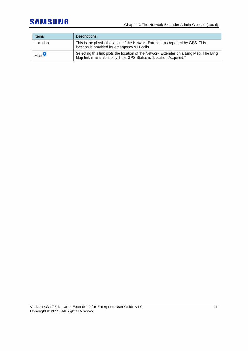
Items Descriptions Location This is the physical location of the Network Extender as reported by GPS. This
location is provided for emergency 911 calls.
Map Selecting this link plots the location of the Network Extender on a Bing Map. The Bing Map link is available only if the GPS Status is “Location Acquired.”
Chapter 3 The Network Extender Admin Website (Local)
Verizon 4G LTE Network Extender 2 for Enterprise User Guide v1.0 42 Copyright © 2019, All Rights Reserved.
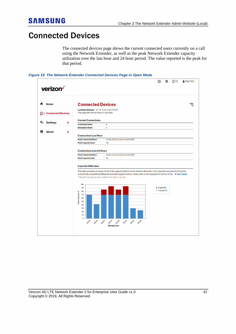
Connected Devices The connected devices page shows the current connected users currently on a call using the Network Extender, as well as the peak Network Extender capacity utilization over the last hour and 24 hour period. The value reported is the peak for that period.
Figure 19. The Network Extender Connected Devices Page in Open Mode
Chapter 3 The Network Extender Admin Website (Local)
Verizon 4G LTE Network Extender 2 for Enterprise User Guide v1.0 43 Copyright © 2019, All Rights Reserved.
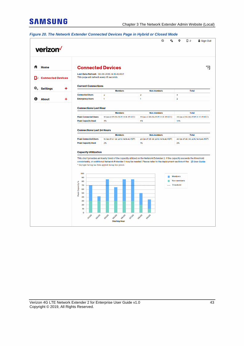
Figure 20. The Network Extender Connected Devices Page in Hybrid or Closed Mode
Chapter 3 The Network Extender Admin Website (Local)
Verizon 4G LTE Network Extender 2 for Enterprise User Guide v1.0 44 Copyright © 2019, All Rights Reserved.
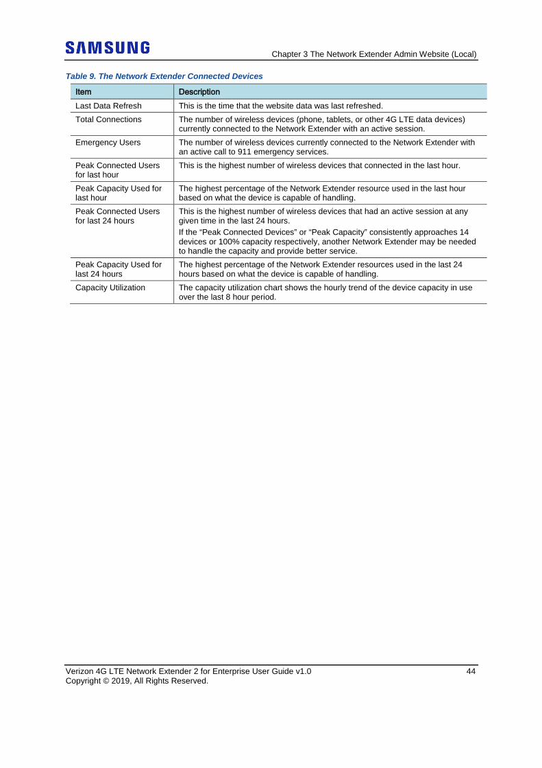
Table 9. The Network Extender Connected Devices
Item Description Last Data Refresh This is the time that the website data was last refreshed. Total Connections The number of wireless devices (phone, tablets, or other 4G LTE data devices)
currently connected to the Network Extender with an active session. Emergency Users The number of wireless devices currently connected to the Network Extender with
an active call to 911 emergency services. Peak Connected Users for last hour
This is the highest number of wireless devices that connected in the last hour.
Peak Capacity Used for last hour
The highest percentage of the Network Extender resource used in the last hour based on what the device is capable of handling.
Peak Connected Users for last 24 hours
This is the highest number of wireless devices that had an active session at any given time in the last 24 hours. If the “Peak Connected Devices” or “Peak Capacity” consistently approaches 14 devices or 100% capacity respectively, another Network Extender may be needed to handle the capacity and provide better service.
Peak Capacity Used for last 24 hours
The highest percentage of the Network Extender resources used in the last 24 hours based on what the device is capable of handling.
Capacity Utilization The capacity utilization chart shows the hourly trend of the device capacity in use over the last 8 hour period.
Chapter 3 The Network Extender Admin Website (Local)
Verizon 4G LTE Network Extender 2 for Enterprise User Guide v1.0 45 Copyright © 2019, All Rights Reserved.
Settings
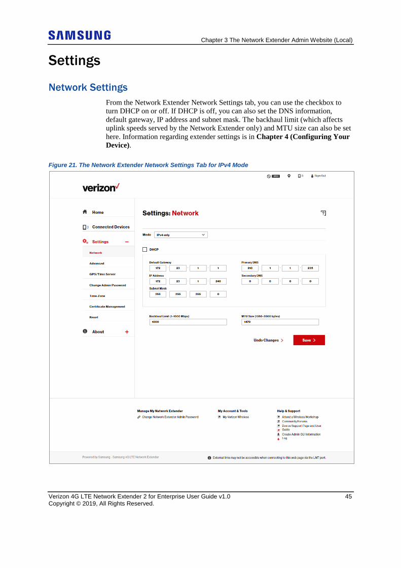
Network Settings From the Network Extender Network Settings tab, you can use the checkbox to turn DHCP on or off. If DHCP is off, you can also set the DNS information, default gateway, IP address and subnet mask. The backhaul limit (which affects uplink speeds served by the Network Extender only) and MTU size can also be set here. Information regarding extender settings is in Chapter 4 (Configuring Your Device).
Figure 21. The Network Extender Network Settings Tab for IPv4 Mode
Chapter 3 The Network Extender Admin Website (Local)
Verizon 4G LTE Network Extender 2 for Enterprise User Guide v1.0 46 Copyright © 2019, All Rights Reserved.
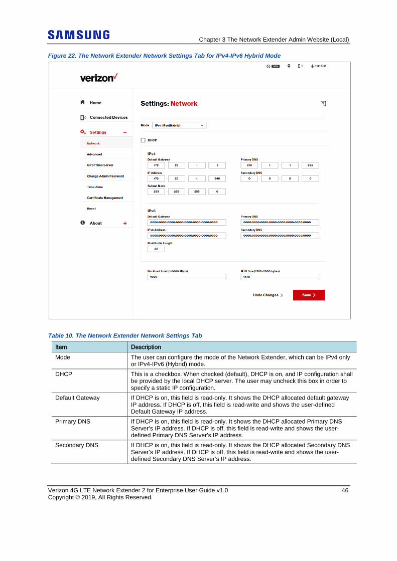
Figure 22. The Network Extender Network Settings Tab for IPv4-IPv6 Hybrid Mode
Table 10. The Network Extender Network Settings Tab
Item Description Mode The user can configure the mode of the Network Extender, which can be IPv4 only
or IPv4-IPv6 (Hybrid) mode. DHCP This is a checkbox. When checked (default), DHCP is on, and IP configuration shall
be provided by the local DHCP server. The user may uncheck this box in order to specify a static IP configuration.
Default Gateway If DHCP is on, this field is read-only. It shows the DHCP allocated default gateway IP address. If DHCP is off, this field is read-write and shows the user-defined Default Gateway IP address.
Primary DNS If DHCP is on, this field is read-only. It shows the DHCP allocated Primary DNS Server’s IP address. If DHCP is off, this field is read-write and shows the user- defined Primary DNS Server’s IP address.
Secondary DNS If DHCP is on, this field is read-only. It shows the DHCP allocated Secondary DNS Server’s IP address. If DHCP is off, this field is read-write and shows the user- defined Secondary DNS Server’s IP address.
Chapter 3 The Network Extender Admin Website (Local)
Verizon 4G LTE Network Extender 2 for Enterprise User Guide v1.0 47 Copyright © 2019, All Rights Reserved.
Item Description IP Address If DHCP is on, this field is read-only. It shows the DHCP allocated IPv4/IPv6
address. If DHCP is off, this field is read-write and shows the user-defined IPv4/IPv6 address.
Subnet Mask If DHCP is on, this field is read-only. It shows the DHCP allocated Subnet Mask. If DHCP is off, this field is read-write and shows the user-defined Subnet Mask.
Backhaul Limit This setting is used to keep the uplink bandwidth consumption rate below the specified limit by limiting uplink traffic. The maximum 1 Gbps value is the default setting, and should not be changed unless there is a strong need to limit the amount of data the Network Extender can send. This uplink Backhaul limit should never be set under 20 Mbps as it will negatively affect voice call quality
MTU Size This is the Maximum Transport Unit (MTU) used to create IP packets. This setting adjusts the maximum packet size for data transmission over the network. The default setting should be used in most cases. If the Maximum Transmission Unit (MTU) size is set too high, users may experience poor voice quality and increased latency in their data service. If set too low, overall bandwidth consumption will be increased and users may experience lower data speeds.
Save Button A Save button is provided to allow the user to commit the changes.
Public NTP server interaction, used for system time initialization If DHCP option 42 is provided in the DHCP response from the local DHCP Server, the Network Extender will try to sync with the local NTP server IP address provided in option 42. If the above is not provided (it’s not mandatory), the Network Extender will try to resolve the following public NTP.org FQDNs and attempt to get NTP sync from the public NTP servers. From the North America NTP Pool ● server 0.north-america.pool.ntp.org ● server 1.north-america.pool.ntp.org NTP uses UDP/TCP port 123
IPv4-IPv6 (Hybrid) mode If the DHCP server only provide IPv6, then Network Extender will not come into service. It will raise an error on the Admin Website to inform the user of this issue.
Chapter 3 The Network Extender Admin Website (Local)
Verizon 4G LTE Network Extender 2 for Enterprise User Guide v1.0 48 Copyright © 2019, All Rights Reserved.
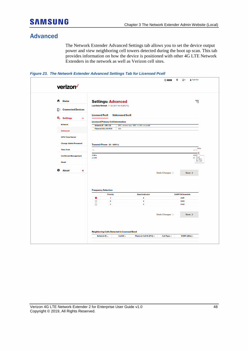
Advanced The Network Extender Advanced Settings tab allows you to set the device output power and view neighboring cell towers detected during the boot up scan. This tab provides information on how the device is positioned with other 4G LTE Network Extenders in the network as well as Verizon cell sites.
Figure 23. The Network Extender Advanced Settings Tab for Licensed Pcell
Chapter 3 The Network Extender Admin Website (Local)
Verizon 4G LTE Network Extender 2 for Enterprise User Guide v1.0 49 Copyright © 2019, All Rights Reserved.
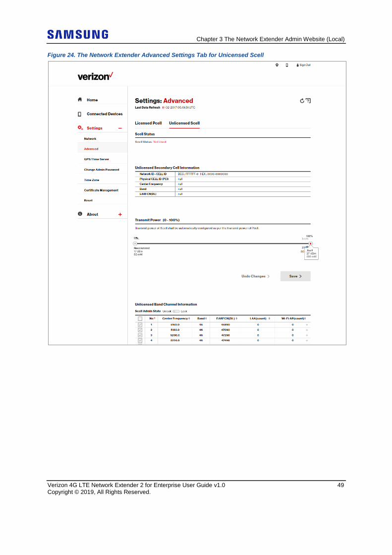
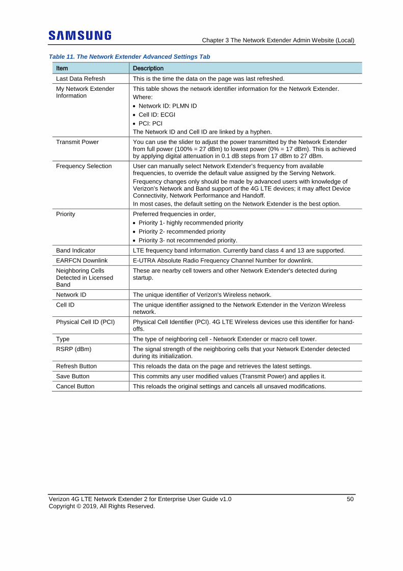
Figure 24. The Network Extender Advanced Settings Tab for Unicensed Scell
Chapter 3 The Network Extender Admin Website (Local)
Verizon 4G LTE Network Extender 2 for Enterprise User Guide v1.0 50 Copyright © 2019, All Rights Reserved.
Table 11. The Network Extender Advanced Settings Tab
Item Description Last Data Refresh This is the time the data on the page was last refreshed. My Network Extender Information
This table shows the network identifier information for the Network Extender. Where: • Network ID: PLMN ID • Cell ID: ECGI • PCI: PCI The Network ID and Cell ID are linked by a hyphen.
Transmit Power You can use the slider to adjust the power transmitted by the Network Extender from full power (100% = 27 dBm) to lowest power (0% = 17 dBm). This is achieved by applying digital attenuation in 0.1 dB steps from 17 dBm to 27 dBm.
Frequency Selection User can manually select Network Extender’s frequency from available frequencies, to override the default value assigned by the Serving Network. Frequency changes only should be made by advanced users with knowledge of Verizon’s Network and Band support of the 4G LTE devices; it may affect Device Connectivity, Network Performance and Handoff. In most cases, the default setting on the Network Extender is the best option.
Priority Preferred frequencies in order, • Priority 1- highly recommended priority • Priority 2- recommended priority • Priority 3- not recommended priority.
Band Indicator LTE frequency band information. Currently band class 4 and 13 are supported. EARFCN Downlink E-UTRA Absolute Radio Frequency Channel Number for downlink. Neighboring Cells Detected in Licensed Band
These are nearby cell towers and other Network Extender's detected during startup.
Network ID The unique identifier of Verizon's Wireless network. Cell ID The unique identifier assigned to the Network Extender in the Verizon Wireless
network. Physical Cell ID (PCI) Physical Cell Identifier (PCI). 4G LTE Wireless devices use this identifier for hand-
offs. Type The type of neighboring cell - Network Extender or macro cell tower. RSRP (dBm) The signal strength of the neighboring cells that your Network Extender detected
during its initialization. Refresh Button This reloads the data on the page and retrieves the latest settings. Save Button This commits any user modified values (Transmit Power) and applies it. Cancel Button This reloads the original settings and cancels all unsaved modifications.
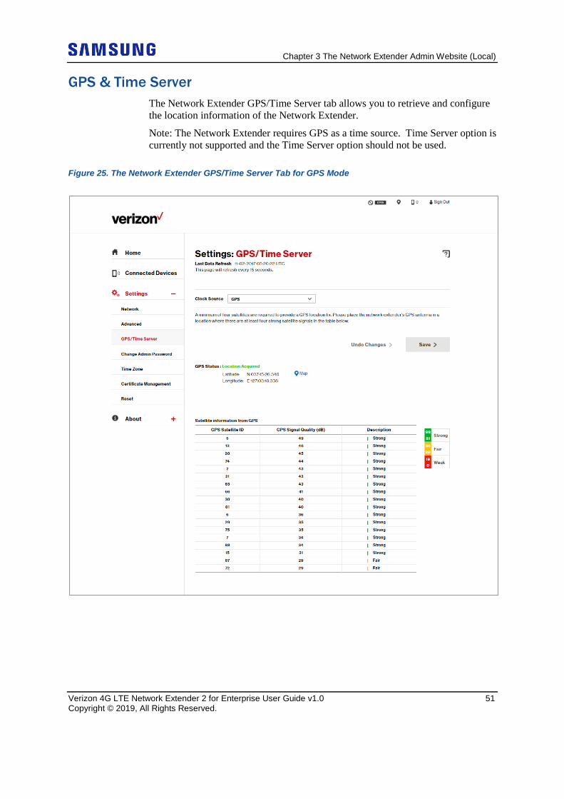
Chapter 3 The Network Extender Admin Website (Local)
Verizon 4G LTE Network Extender 2 for Enterprise User Guide v1.0 51 Copyright © 2019, All Rights Reserved.
GPS & Time Server The Network Extender GPS/Time Server tab allows you to retrieve and configure the location information of the Network Extender.
Note: The Network Extender requires GPS as a time source. Time Server option is currently not supported and the Time Server option should not be used.
Figure 25. The Network Extender GPS/Time Server Tab for GPS Mode
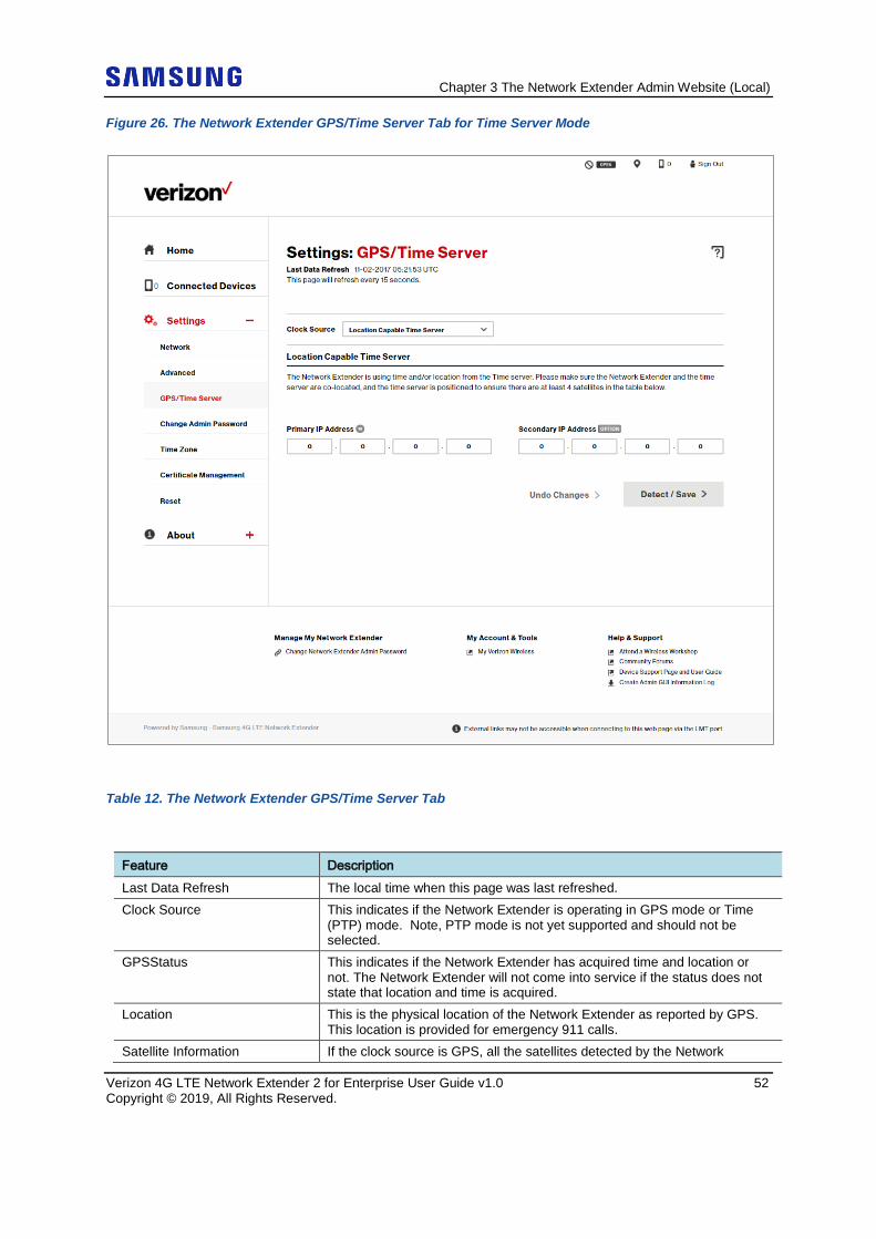
Chapter 3 The Network Extender Admin Website (Local)
Verizon 4G LTE Network Extender 2 for Enterprise User Guide v1.0 52 Copyright © 2019, All Rights Reserved.
Figure 26. The Network Extender GPS/Time Server Tab for Time Server Mode
Table 12. The Network Extender GPS/Time Server Tab
Feature Description Last Data Refresh The local time when this page was last refreshed. Clock Source This indicates if the Network Extender is operating in GPS mode or Time
(PTP) mode. Note, PTP mode is not yet supported and should not be selected.
GPSStatus This indicates if the Network Extender has acquired time and location or not. The Network Extender will not come into service if the status does not state that location and time is acquired.
Location This is the physical location of the Network Extender as reported by GPS. This location is provided for emergency 911 calls.
Satellite Information If the clock source is GPS, all the satellites detected by the Network
Chapter 3 The Network Extender Admin Website (Local)
Verizon 4G LTE Network Extender 2 for Enterprise User Guide v1.0 53 Copyright © 2019, All Rights Reserved.
Feature Description Extender’s GPS, will be displayed.
GPS Satellite ID The list of GPS satellites identifies how many satellites are currently being detected along with each satellite's unique identifier.
GPS Signal Quality (dB) This chart displays the minimum/maximum/average of SNR (dB) for last 24 hours.
Description Describes the quality level of the satellite signal as either: Strong, Fair, Weak or No Signal.
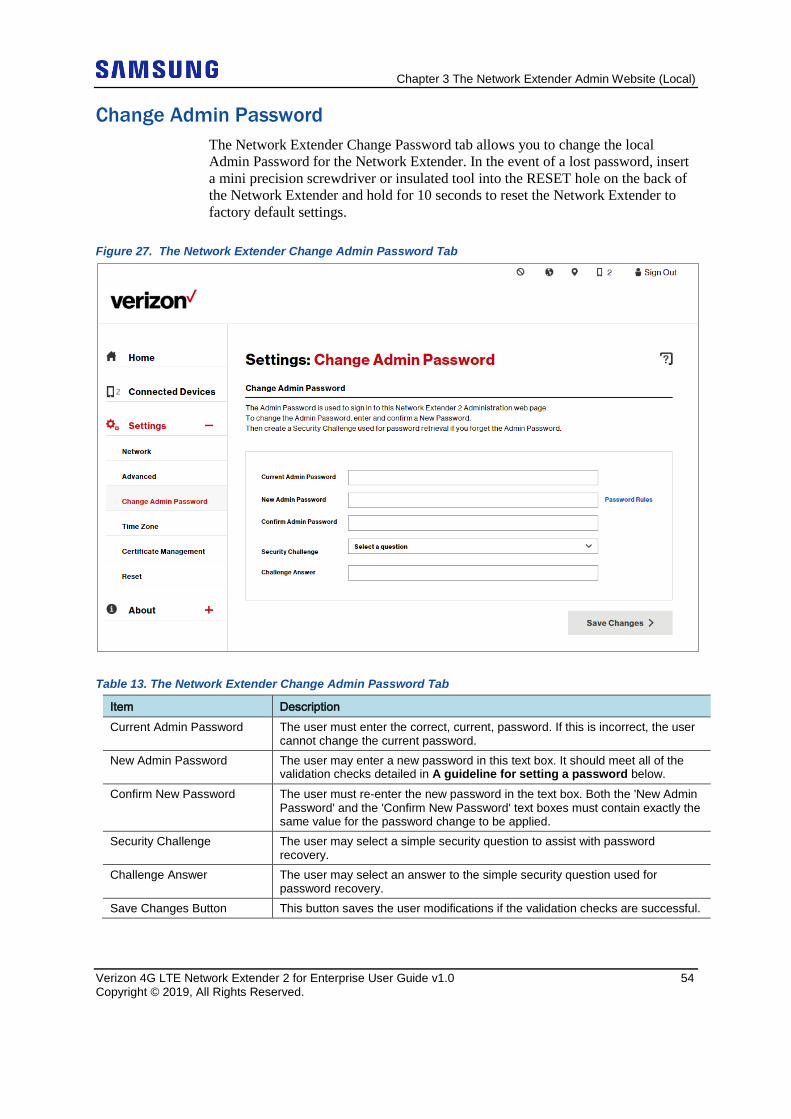
Chapter 3 The Network Extender Admin Website (Local)
Verizon 4G LTE Network Extender 2 for Enterprise User Guide v1.0 54 Copyright © 2019, All Rights Reserved.
Change Admin Password The Network Extender Change Password tab allows you to change the local Admin Password for the Network Extender. In the event of a lost password, insert a mini precision screwdriver or insulated tool into the RESET hole on the back of the Network Extender and hold for 10 seconds to reset the Network Extender to factory default settings.
Figure 27. The Network Extender Change Admin Password Tab
Table 13. The Network Extender Change Admin Password Tab
Item Description Current Admin Password The user must enter the correct, current, password. If this is incorrect, the user
cannot change the current password. New Admin Password The user may enter a new password in this text box. It should meet all of the
validation checks detailed in A guideline for setting a password below. Confirm New Password The user must re-enter the new password in the text box. Both the 'New Admin
Password' and the 'Confirm New Password' text boxes must contain exactly the same value for the password change to be applied.
Security Challenge The user may select a simple security question to assist with password recovery.
Challenge Answer The user may select an answer to the simple security question used for password recovery.
Save Changes Button This button saves the user modifications if the validation checks are successful.
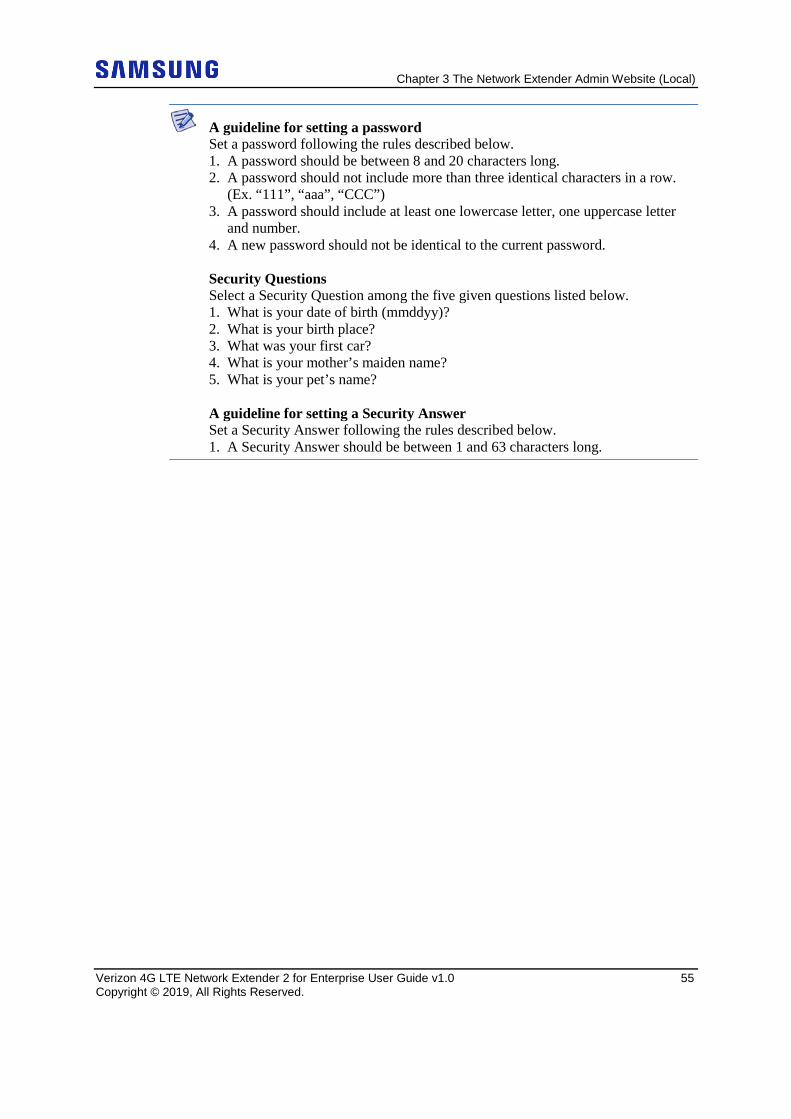
Chapter 3 The Network Extender Admin Website (Local)
Verizon 4G LTE Network Extender 2 for Enterprise User Guide v1.0 55 Copyright © 2019, All Rights Reserved.
A guideline for setting a password Set a password following the rules described below. 1. A password should be between 8 and 20 characters long. 2. A password should not include more than three identical characters in a row. (Ex. “111”, “aaa”, “CCC”) 3. A password should include at least one lowercase letter, one uppercase letter and number. 4. A new password should not be identical to the current password. Security Questions Select a Security Question among the five given questions listed below. 1. What is your date of birth (mmddyy)? 2. What is your birth place? 3. What was your first car? 4. What is your mother’s maiden name? 5. What is your pet’s name? A guideline for setting a Security Answer Set a Security Answer following the rules described below. 1. A Security Answer should be between 1 and 63 characters long.
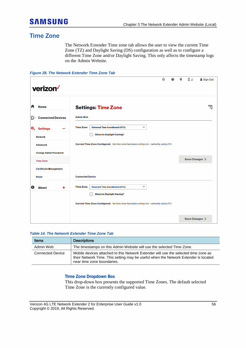
Chapter 3 The Network Extender Admin Website (Local)
Verizon 4G LTE Network Extender 2 for Enterprise User Guide v1.0 56 Copyright © 2019, All Rights Reserved.
Time Zone The Network Extender Time zone tab allows the user to view the current Time Zone (TZ) and Daylight Saving (DS) configuration as well as to configure a different Time Zone and/or Daylight Saving. This only affects the timestamp logs on the Admin Website.
Figure 28. The Network Extender Time Zone Tab
Table 14. The Network Extender Time Zone Tab
Items Descriptions Admin Web The timestamps on this Admin Website will use the selected Time Zone. Connected Device Mobile devices attached to this Network Extender will use the selected time zone as
their Network Time. This setting may be useful when the Network Extender is located near time zone boundaries.
Time Zone Dropdown Box This drop-down box presents the supported Time Zones. The default selected Time Zone is the currently configured value.
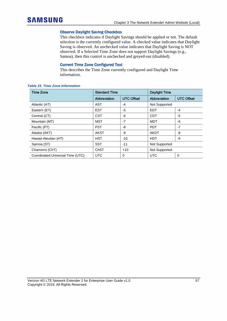
Chapter 3 The Network Extender Admin Website (Local)
Verizon 4G LTE Network Extender 2 for Enterprise User Guide v1.0 57 Copyright © 2019, All Rights Reserved.
Observe Daylight Saving Checkbox This checkbox indicates if Daylight Savings should be applied or not. The default selection is the currently configured value. A checked value indicates that Daylight Saving is observed. An unchecked value indicates that Daylight Saving is NOT observed. If a Selected Time Zone does not support Daylight Savings (e.g., Samoa), then this control is unchecked and greyed-out (disabled).
Current Time Zone Configured Text This describes the Time Zone currently configured and Daylight Time information.
Table 15. Time Zone Information
Time Zone Standard Time Daylight Time
Abbreviation UTC Offset Abbreviation UTC Offset Atlantic (AT) AST -4 Not Supported Eastern (ET) EST -5 EDT -4 Central (CT) CST -6 CDT -5 Mountain (MT) MST -7 MDT -6 Pacific (PT) PST -8 PDT -7 Alaska (AKT) AKST -9 AKDT -8 Hawaii-Aleutian (HT) HST -10 HDT -9 Samoa (ST) SST -11 Not Supported Chamorro (ChT) ChST +10 Not Supported Coordinated Universal Time (UTC) UTC 0 UTC 0
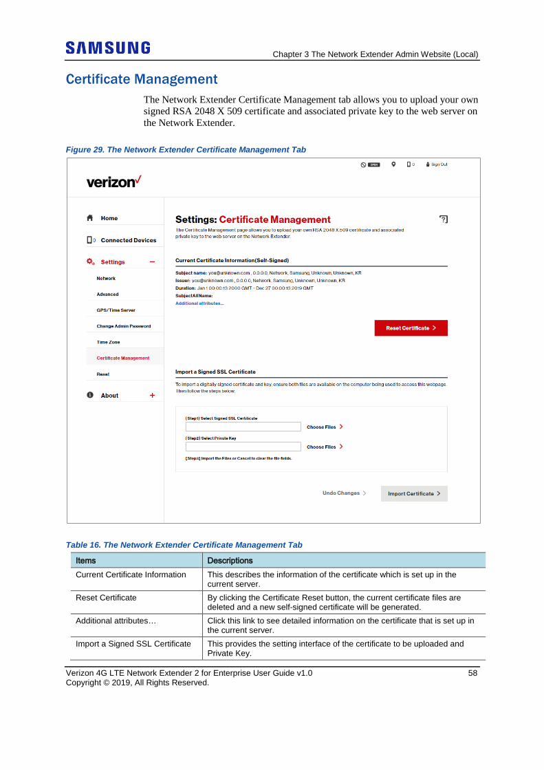
Chapter 3 The Network Extender Admin Website (Local)
Verizon 4G LTE Network Extender 2 for Enterprise User Guide v1.0 58 Copyright © 2019, All Rights Reserved.
Certificate Management The Network Extender Certificate Management tab allows you to upload your own signed RSA 2048 X 509 certificate and associated private key to the web server on the Network Extender.
Figure 29. The Network Extender Certificate Management Tab
Table 16. The Network Extender Certificate Management Tab
Items Descriptions Current Certificate Information This describes the information of the certificate which is set up in the
current server. Reset Certificate By clicking the Certificate Reset button, the current certificate files are
deleted and a new self-signed certificate will be generated. Additional attributes… Click this link to see detailed information on the certificate that is set up in
the current server. Import a Signed SSL Certificate This provides the setting interface of the certificate to be uploaded and
Private Key.
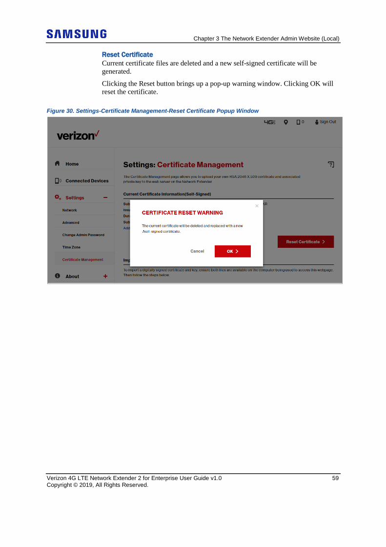
Chapter 3 The Network Extender Admin Website (Local)
Verizon 4G LTE Network Extender 2 for Enterprise User Guide v1.0 59 Copyright © 2019, All Rights Reserved.
Reset Certificate Current certificate files are deleted and a new self-signed certificate will be generated.
Clicking the Reset button brings up a pop-up warning window. Clicking OK will reset the certificate.
Figure 30. Settings-Certificate Management-Reset Certificate Popup Window
Chapter 3 The Network Extender Admin Website (Local)
Verizon 4G LTE Network Extender 2 for Enterprise User Guide v1.0 60 Copyright © 2019, All Rights Reserved.
Import a Signed SSL Certificate • Introduction
The Certificate Management page allows you to upload your own RSA 2048 X.509 Certificate and associated Private Key to the web server on the Network Extender. By installing your own certificate, security warning, prompts such as “Warning Invalid Certificate” in your web browser, will be suppressed when attempting to access the Network Extender’s website.
• Obtaining and Installing Certificates Installing a certificate involves the following steps:
a Generating a Private Key Generate an RSA 2048 private key in PEM format with a “.prv” extension type. The Certificate Authority you choose to use will provide specific instructions on how to generate the private key.
b Generating a CSR (Certificate Signing Request) Generate a CSR for an RSA 2048 certificate in PEM format with the “.PEM” extension type using the private key created in Step A. The Certificate Authority you choose to use will provide specific instructions on how to generate the CSR.
The “common name” field in the CSR must match the FQDN you put in the internal DNS (Domain Name Service) and the Network Extender will need to be configured with a static IP address matching the DNS entry in your server.
c Send the CSR to the Certificate Authority to receive a signed certificate file. The Certificate Authority you choose to use will provide instructions on how to send the CSR for signing and receiving the signed RSA 2048 certificate in PEM format. It is important to let the Certificate Authority know that the full concatenated chain of certificates must be included in your certificate file. When the signed certificate is received from the Certificate Authority, ensure it and the private key files are placed on the computer connected directly to the Network Extender.
d Follow the steps on the Certificate Management page to install the certificate and private key files. Below are instructions on installing the certificate and private key file. There should be two files prepared on your connected computer before uploading.
• File Verification Process After the files are uploaded, the certificates are verified. If verification fails, the Certificate Management page will reappear and the import can be tried again. If verification is successful, you will be prompted to sign back into the Network Extender’s home page using https and the newly installed certificate.
Chapter 3 The Network Extender Admin Website (Local)
Verizon 4G LTE Network Extender 2 for Enterprise User Guide v1.0 61 Copyright © 2019, All Rights Reserved.
● Certificate File This file contains the entire concatenated certificate which includes your RSA 2048 certificate followed by all intermediate signing certificates and ending with the root certificate. This certificate file must be in PEM format and have a “.PEM” extension type. ● Private Key File This file contains the RSA 2048 private key in PEM format and uses a “.prv” extension type.
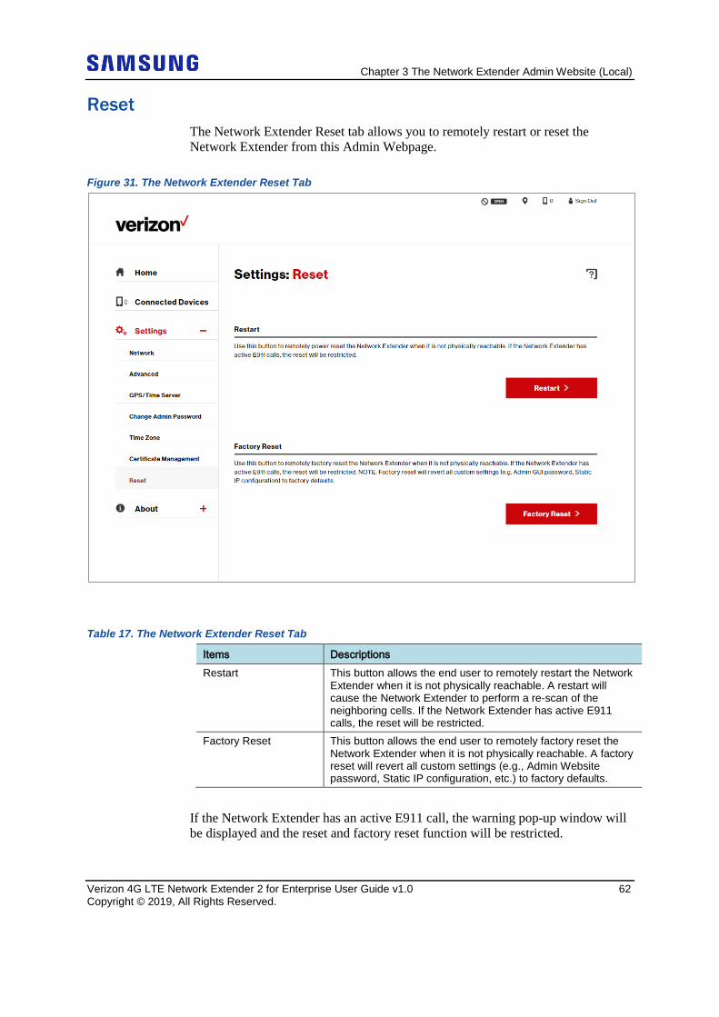
Chapter 3 The Network Extender Admin Website (Local)
Verizon 4G LTE Network Extender 2 for Enterprise User Guide v1.0 62 Copyright © 2019, All Rights Reserved.
Reset The Network Extender Reset tab allows you to remotely restart or reset the Network Extender from this Admin Webpage.
Figure 31. The Network Extender Reset Tab
Table 17. The Network Extender Reset Tab
Items Descriptions Restart This button allows the end user to remotely restart the Network
Extender when it is not physically reachable. A restart will cause the Network Extender to perform a re-scan of the neighboring cells. If the Network Extender has active E911 calls, the reset will be restricted.
Factory Reset This button allows the end user to remotely factory reset the Network Extender when it is not physically reachable. A factory reset will revert all custom settings (e.g., Admin Website password, Static IP configuration, etc.) to factory defaults.
If the Network Extender has an active E911 call, the warning pop-up window will be displayed and the reset and factory reset function will be restricted.
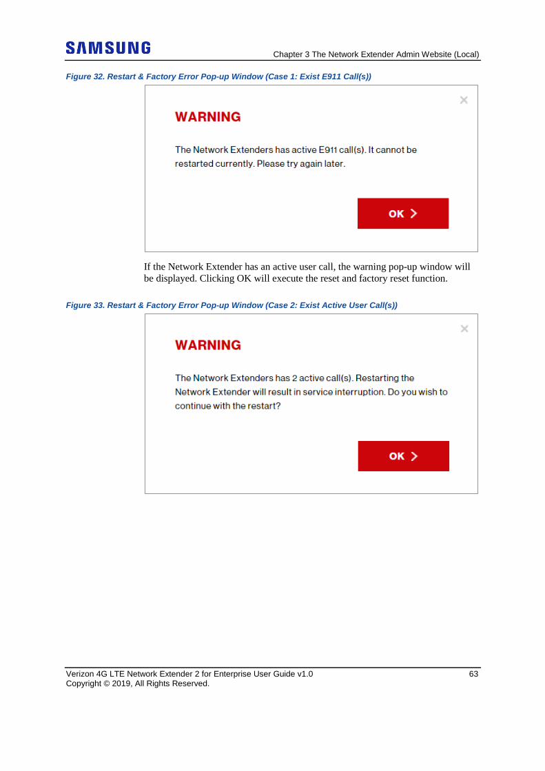
Chapter 3 The Network Extender Admin Website (Local)
Verizon 4G LTE Network Extender 2 for Enterprise User Guide v1.0 63 Copyright © 2019, All Rights Reserved.
Figure 32. Restart & Factory Error Pop-up Window (Case 1: Exist E911 Call(s))
If the Network Extender has an active user call, the warning pop-up window will be displayed. Clicking OK will execute the reset and factory reset function.
Figure 33. Restart & Factory Error Pop-up Window (Case 2: Exist Active User Call(s))
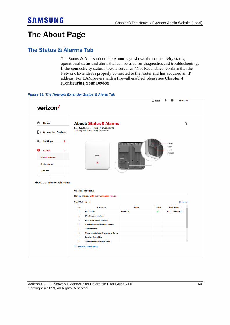
Chapter 3 The Network Extender Admin Website (Local)
Verizon 4G LTE Network Extender 2 for Enterprise User Guide v1.0 64 Copyright © 2019, All Rights Reserved.
The About Page
The Status & Alarms Tab The Status & Alerts tab on the About page shows the connectivity status, operational status and alerts that can be used for diagnostics and troubleshooting. If the connectivity status shows a server as “Not Reachable,” confirm that the Network Extender is properly connected to the router and has acquired an IP address. For LAN/routers with a firewall enabled, please see Chapter 4 (Configuring Your Device).
Figure 34. The Network Extender Status & Alerts Tab
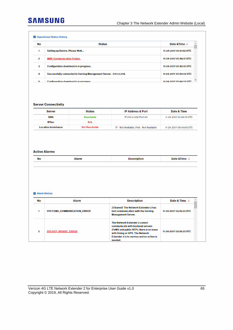
Chapter 3 The Network Extender Admin Website (Local)
Verizon 4G LTE Network Extender 2 for Enterprise User Guide v1.0 65 Copyright © 2019, All Rights Reserved.
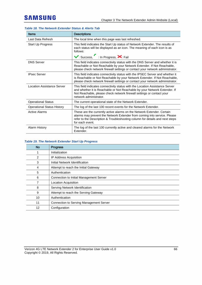
Chapter 3 The Network Extender Admin Website (Local)
Verizon 4G LTE Network Extender 2 for Enterprise User Guide v1.0 66 Copyright © 2019, All Rights Reserved.
Table 18. The Network Extender Status & Alerts Tab
Items Descriptions Last Data Refresh The local time when this page was last refreshed. Start Up Progress This field indicates the Start Up status of Network Extender. The results of
each status will be displayed as an icon. The meaning of each icon is as follows:
: Success, : In Progress, : Fail DNS Server This field indicates connectivity status with the DNS Server and whether it is
Reachable or Not Reachable by your Network Extender. If Not Reachable, please check network firewall settings or contact your network administrator.
IPsec Server This field indicates connectivity status with the IPSEC Server and whether it is Reachable or Not Reachable by your Network Extender. If Not Reachable, please check network firewall settings or contact your network administrator.
Location Assistance Server This field indicates connectivity status with the Location Assistance Server and whether it is Reachable or Not Reachable by your Network Extender. If Not Reachable, please check network firewall settings or contact your network administrator.
Operational Status The current operational state of the Network Extender. Operational Status History The log of the last 100 recent events for the Network Extender. Active Alarms These are the currently active alarms on the Network Extender. Certain
alarms may prevent the Network Extender from coming into service. Please refer to the Description & Troubleshooting column for details and next steps for each event.
Alarm History The log of the last 100 currently active and cleared alarms for the Network Extender.
Table 19. The Network Extender Start Up Progress
No Progress 1 Initialization 2 IP Address Acquisition 3 Initial Network Identification 4 Attempt to reach the Initial Gateway 5 Authentication 6 Connection to Initial Management Server 7 Location Acquisition 8 Serving Network Identification 9 Attempt to reach the Serving Gateway
10 Authentication 11 Connection to Serving Management Server 12 Configuration
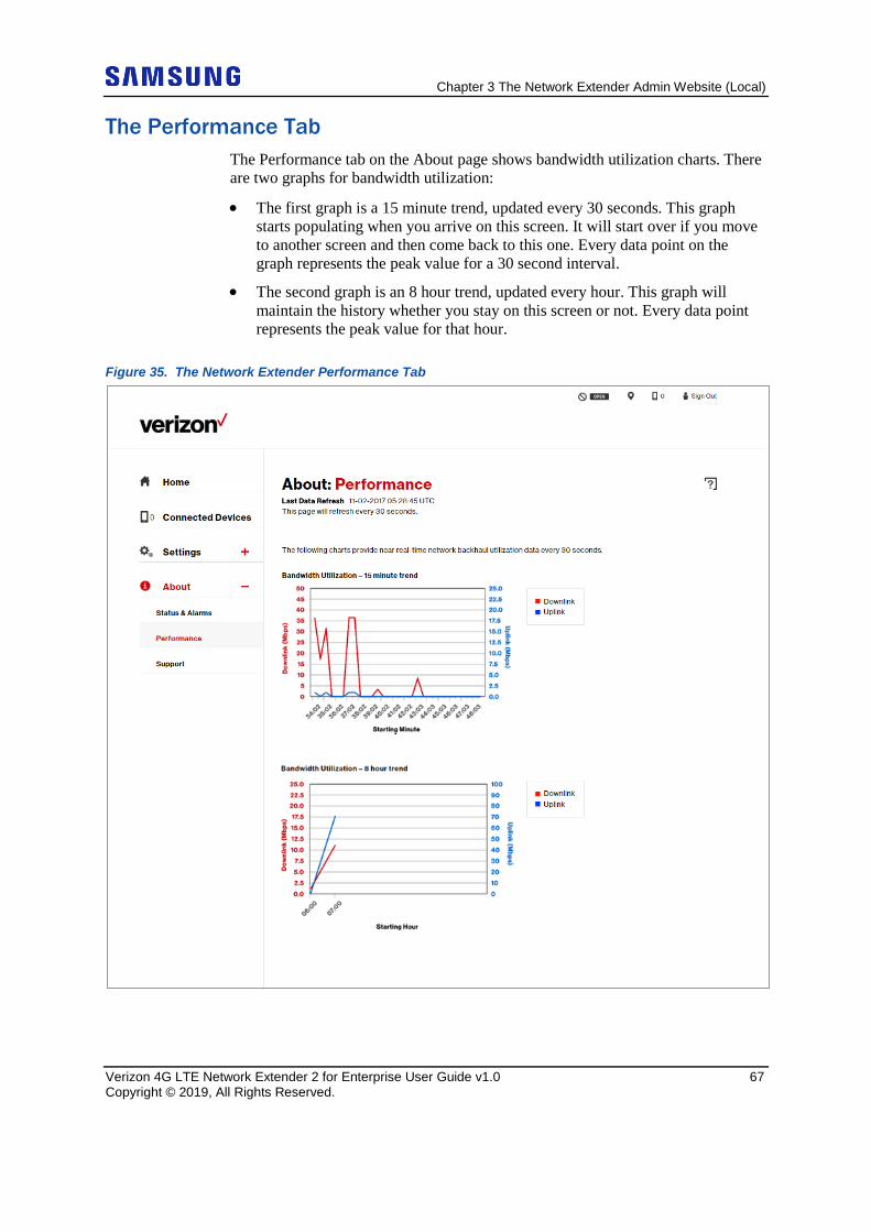
Chapter 3 The Network Extender Admin Website (Local)
Verizon 4G LTE Network Extender 2 for Enterprise User Guide v1.0 67 Copyright © 2019, All Rights Reserved.
The Performance Tab The Performance tab on the About page shows bandwidth utilization charts. There are two graphs for bandwidth utilization:
• The first graph is a 15 minute trend, updated every 30 seconds. This graph starts populating when you arrive on this screen. It will start over if you move to another screen and then come back to this one. Every data point on the graph represents the peak value for a 30 second interval.
• The second graph is an 8 hour trend, updated every hour. This graph will maintain the history whether you stay on this screen or not. Every data point represents the peak value for that hour.
Figure 35. The Network Extender Performance Tab
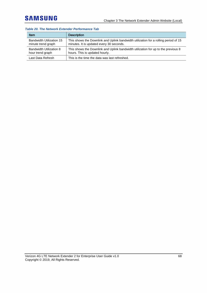
Chapter 3 The Network Extender Admin Website (Local)
Verizon 4G LTE Network Extender 2 for Enterprise User Guide v1.0 68 Copyright © 2019, All Rights Reserved.
Table 20. The Network Extender Performance Tab
Item Description Bandwidth Utilization 15 minute trend graph
This shows the Downlink and Uplink bandwidth utilization for a rolling period of 15 minutes. It is updated every 30 seconds.
Bandwidth Utilization 8 hour trend graph
This shows the Downlink and Uplink bandwidth utilization for up to the previous 8 hours. This is updated hourly.
Last Data Refresh This is the time the data was last refreshed.
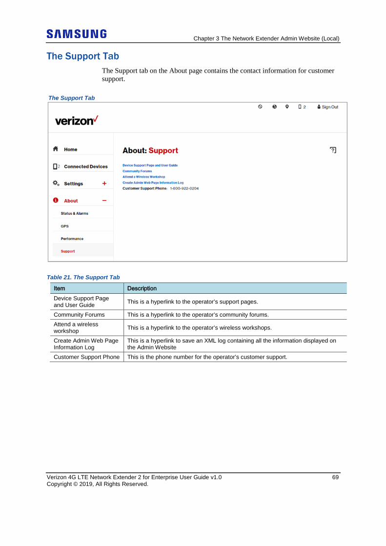
Chapter 3 The Network Extender Admin Website (Local)
Verizon 4G LTE Network Extender 2 for Enterprise User Guide v1.0 69 Copyright © 2019, All Rights Reserved.
The Support Tab The Support tab on the About page contains the contact information for customer support.
The Support Tab
Table 21. The Support Tab
Item Description Device Support Page and User Guide This is a hyperlink to the operator’s support pages.
Community Forums This is a hyperlink to the operator’s community forums. Attend a wireless workshop This is a hyperlink to the operator’s wireless workshops.
Create Admin Web Page Information Log
This is a hyperlink to save an XML log containing all the information displayed on the Admin Website
Customer Support Phone This is the phone number for the operator’s customer support.
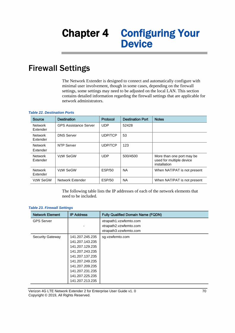
Verizon 4G LTE Network Extender 2 for Enterprise User Guide v1. 0 70 Copyright © 2019, All Rights Reserved.
Chapter 4 Configuring Your Device
Firewall Settings The Network Extender is designed to connect and automatically configure with minimal user involvement, though in some cases, depending on the firewall settings, some settings may need to be adjusted on the local LAN. This section contains detailed information regarding the firewall settings that are applicable for network administrators.
Table 22. Destination Ports
Source Destination Protocol Destination Port Notes Network Extender
GPS Assistance Server UDP 52428
Network Extender
DNS Server UDP/TCP 53
Network Extender
NTP Server UDP/TCP 123
Network Extender
VzW SeGW UDP 500/4500 More than one port may be used for multiple device installation
Network Extender
VzW SeGW ESP/50 NA When NAT/PAT is not present
VzW SeGW Network Extender ESP/50 NA When NAT/PAT is not present
The following table lists the IP addresses of each of the network elements that need to be included.
Table 23. Firewall Settings
Network Element IP Address Fully Qualified Domain Name (FQDN) GPS Server
- xtrapath1.vzwfemto.com xtrapath2.vzwfemto.com xtrapath3.vzwfemto.com
Security Gateway 141.207.245.235 141.207.143.235 141.207.129.235 141.207.243.235 141.207.137.235 141.207.249.235 141.207.209.235 141.207.231.235 141.207.225.235 141.207.213.235
sg.vzwfemto.com
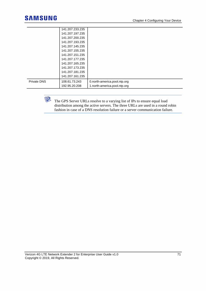
Chapter 4 Configuring Your Device
Verizon 4G LTE Network Extender 2 for Enterprise User Guide v1.0 71 Copyright © 2019, All Rights Reserved.
141.207.233.235 141.207.197.235 141.207.200.235 141.207.193.235 141.207.145.235 141.207.155.235 141.207.151.235 141.207.177.235 141.207.165.235 141.207.173.235 141.207.181.235 141.207.161.235
Private DNS 108.61.73.243 192.95.20.208
0.north-america.pool.ntp.org 1.north-america.pool.ntp.org
The GPS Server URLs resolve to a varying list of IPs to ensure equal load distribution among the active servers. The three URLs are used in a round robin fashion in case of a DNS resolution failure or a server communication failure.
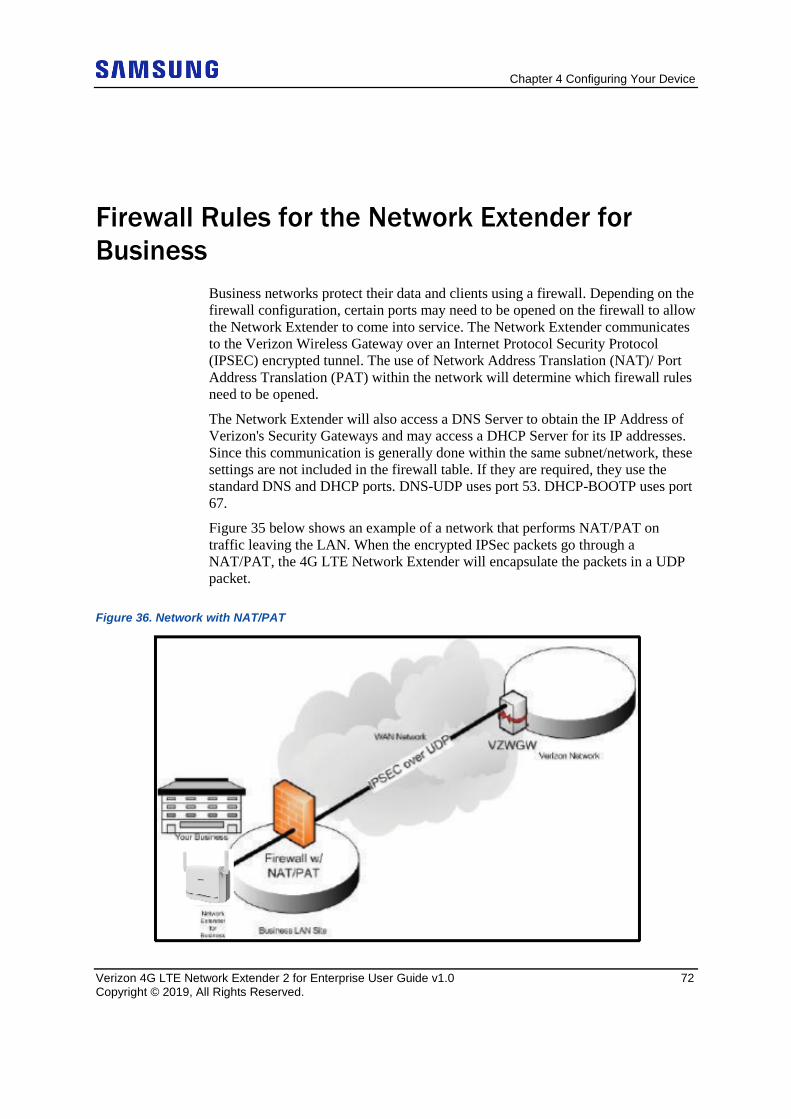
Chapter 4 Configuring Your Device
Verizon 4G LTE Network Extender 2 for Enterprise User Guide v1.0 72 Copyright © 2019, All Rights Reserved.
Firewall Rules for the Network Extender for Business
Business networks protect their data and clients using a firewall. Depending on the firewall configuration, certain ports may need to be opened on the firewall to allow the Network Extender to come into service. The Network Extender communicates to the Verizon Wireless Gateway over an Internet Protocol Security Protocol (IPSEC) encrypted tunnel. The use of Network Address Translation (NAT)/ Port Address Translation (PAT) within the network will determine which firewall rules need to be opened.
The Network Extender will also access a DNS Server to obtain the IP Address of Verizon's Security Gateways and may access a DHCP Server for its IP addresses. Since this communication is generally done within the same subnet/network, these settings are not included in the firewall table. If they are required, they use the standard DNS and DHCP ports. DNS-UDP uses port 53. DHCP-BOOTP uses port 67.
Figure 35 below shows an example of a network that performs NAT/PAT on traffic leaving the LAN. When the encrypted IPSec packets go through a NAT/PAT, the 4G LTE Network Extender will encapsulate the packets in a UDP packet.
Figure 36. Network with NAT/PAT

Chapter 4 Configuring Your Device
Verizon 4G LTE Network Extender 2 for Enterprise User Guide v1.0 73 Copyright © 2019, All Rights Reserved.
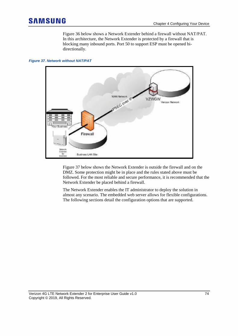
Chapter 4 Configuring Your Device
Verizon 4G LTE Network Extender 2 for Enterprise User Guide v1.0 74 Copyright © 2019, All Rights Reserved.
Figure 36 below shows a Network Extender behind a firewall without NAT/PAT. In this architecture, the Network Extender is protected by a firewall that is blocking many inbound ports. Port 50 to support ESP must be opened bi-directionally.
Figure 37. Network without NAT/PAT
Figure 37 below shows the Network Extender is outside the firewall and on the DMZ. Some protection might be in place and the rules stated above must be followed. For the most reliable and secure performance, it is recommended that the Network Extender be placed behind a firewall.
The Network Extender enables the IT administrator to deploy the solution in almost any scenario. The embedded web server allows for flexible configurations. The following sections detail the configuration options that are supported.
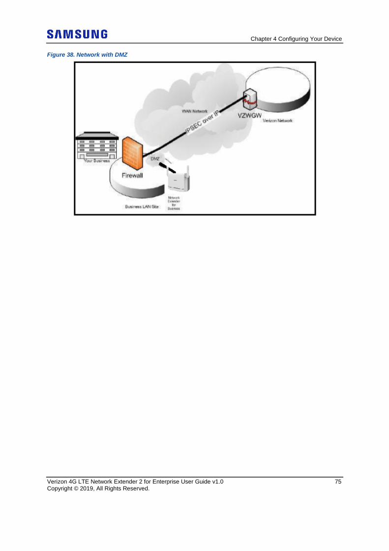
Chapter 4 Configuring Your Device
Verizon 4G LTE Network Extender 2 for Enterprise User Guide v1.0 75 Copyright © 2019, All Rights Reserved.
Figure 38. Network with DMZ
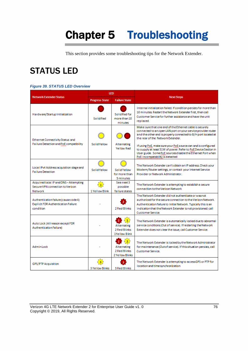
Verizon 4G LTE Network Extender 2 for Enterprise User Guide v1. 0 76 Copyright © 2019, All Rights Reserved.
Chapter 5 Troubleshooting This section provides some troubleshooting tips for the Network Extender.
STATUS LED Figure 39. STATUS LED Overview
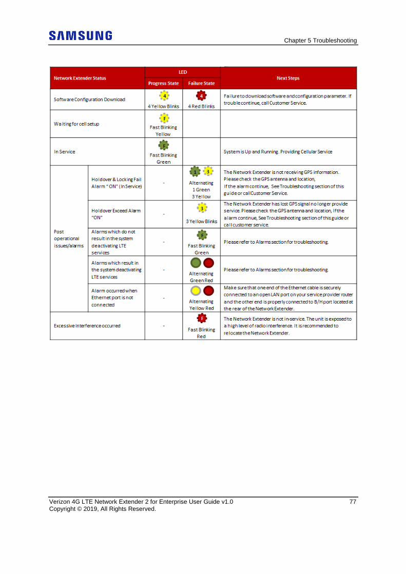
Chapter 5 Troubleshooting
Verizon 4G LTE Network Extender 2 for Enterprise User Guide v1.0 77 Copyright © 2019, All Rights Reserved.
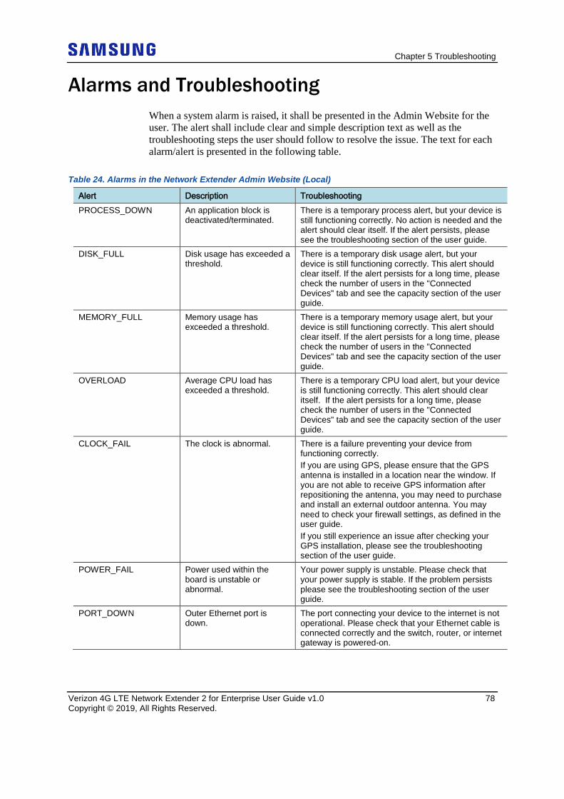
Chapter 5 Troubleshooting
Verizon 4G LTE Network Extender 2 for Enterprise User Guide v1.0 78 Copyright © 2019, All Rights Reserved.
Alarms and Troubleshooting
When a system alarm is raised, it shall be presented in the Admin Website for the user. The alert shall include clear and simple description text as well as the troubleshooting steps the user should follow to resolve the issue. The text for each alarm/alert is presented in the following table.
Table 24. Alarms in the Network Extender Admin Website (Local)
Alert Description Troubleshooting PROCESS_DOWN An application block is
deactivated/terminated. There is a temporary process alert, but your device is still functioning correctly. No action is needed and the alert should clear itself. If the alert persists, please see the troubleshooting section of the user guide.
DISK_FULL Disk usage has exceeded a threshold.
There is a temporary disk usage alert, but your device is still functioning correctly. This alert should clear itself. If the alert persists for a long time, please check the number of users in the "Connected Devices" tab and see the capacity section of the user guide.
MEMORY_FULL Memory usage has exceeded a threshold.
There is a temporary memory usage alert, but your device is still functioning correctly. This alert should clear itself. If the alert persists for a long time, please check the number of users in the "Connected Devices" tab and see the capacity section of the user guide.
OVERLOAD Average CPU load has exceeded a threshold.
There is a temporary CPU load alert, but your device is still functioning correctly. This alert should clear itself. If the alert persists for a long time, please check the number of users in the "Connected Devices" tab and see the capacity section of the user guide.
CLOCK_FAIL The clock is abnormal. There is a failure preventing your device from functioning correctly. If you are using GPS, please ensure that the GPS antenna is installed in a location near the window. If you are not able to receive GPS information after repositioning the antenna, you may need to purchase and install an external outdoor antenna. You may need to check your firewall settings, as defined in the user guide. If you still experience an issue after checking your GPS installation, please see the troubleshooting section of the user guide.
POWER_FAIL Power used within the board is unstable or abnormal.
Your power supply is unstable. Please check that your power supply is stable. If the problem persists please see the troubleshooting section of the user guide.
PORT_DOWN Outer Ethernet port is down.
The port connecting your device to the internet is not operational. Please check that your Ethernet cable is connected correctly and the switch, router, or internet gateway is powered-on.
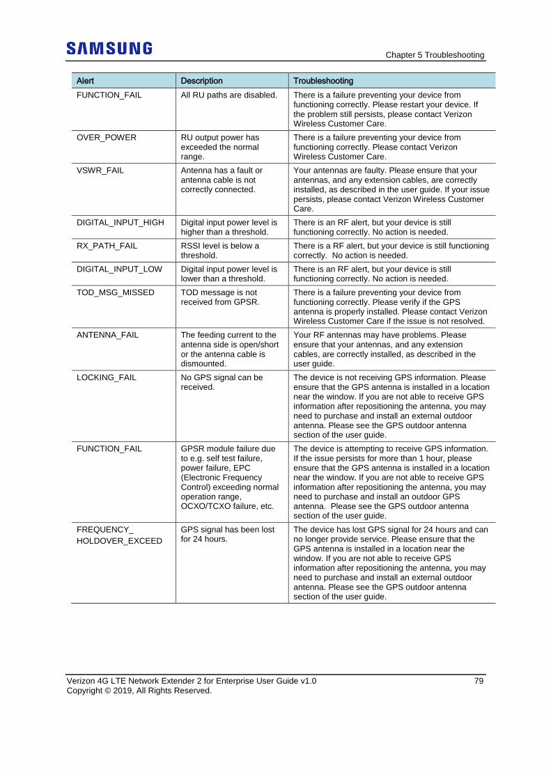
Chapter 5 Troubleshooting
Verizon 4G LTE Network Extender 2 for Enterprise User Guide v1.0 79 Copyright © 2019, All Rights Reserved.
Alert Description Troubleshooting FUNCTION_FAIL All RU paths are disabled. There is a failure preventing your device from
functioning correctly. Please restart your device. If the problem still persists, please contact Verizon Wireless Customer Care.
OVER_POWER RU output power has exceeded the normal range.
There is a failure preventing your device from functioning correctly. Please contact Verizon Wireless Customer Care.
VSWR_FAIL Antenna has a fault or antenna cable is not correctly connected.
Your antennas are faulty. Please ensure that your antennas, and any extension cables, are correctly installed, as described in the user guide. If your issue persists, please contact Verizon Wireless Customer Care.
DIGITAL_INPUT_HIGH Digital input power level is higher than a threshold.
There is an RF alert, but your device is still functioning correctly. No action is needed.
RX_PATH_FAIL RSSI level is below a threshold.
There is a RF alert, but your device is still functioning correctly. No action is needed.
DIGITAL_INPUT_LOW Digital input power level is lower than a threshold.
There is an RF alert, but your device is still functioning correctly. No action is needed.
TOD_MSG_MISSED TOD message is not received from GPSR.
There is a failure preventing your device from functioning correctly. Please verify if the GPS antenna is properly installed. Please contact Verizon Wireless Customer Care if the issue is not resolved.
ANTENNA_FAIL The feeding current to the antenna side is open/short or the antenna cable is dismounted.
Your RF antennas may have problems. Please ensure that your antennas, and any extension cables, are correctly installed, as described in the user guide.
LOCKING_FAIL No GPS signal can be received.
The device is not receiving GPS information. Please ensure that the GPS antenna is installed in a location near the window. If you are not able to receive GPS information after repositioning the antenna, you may need to purchase and install an external outdoor antenna. Please see the GPS outdoor antenna section of the user guide.
FUNCTION_FAIL GPSR module failure due to e.g. self test failure, power failure, EPC (Electronic Frequency Control) exceeding normal operation range, OCXO/TCXO failure, etc.
The device is attempting to receive GPS information. If the issue persists for more than 1 hour, please ensure that the GPS antenna is installed in a location near the window. If you are not able to receive GPS information after repositioning the antenna, you may need to purchase and install an outdoor GPS antenna. Please see the GPS outdoor antenna section of the user guide.
FREQUENCY_ HOLDOVER_EXCEED
GPS signal has been lost for 24 hours.
The device has lost GPS signal for 24 hours and can no longer provide service. Please ensure that the GPS antenna is installed in a location near the window. If you are not able to receive GPS information after repositioning the antenna, you may need to purchase and install an external outdoor antenna. Please see the GPS outdoor antenna section of the user guide.
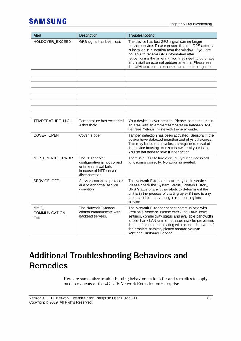
Chapter 5 Troubleshooting
Verizon 4G LTE Network Extender 2 for Enterprise User Guide v1.0 80 Copyright © 2019, All Rights Reserved.
Alert Description Troubleshooting HOLDOVER_EXCEED GPS signal has been lost. The device has lost GPS signal can no longer
provide service. Please ensure that the GPS antenna is installed in a location near the window. If you are not able to receive GPS information after repositioning the antenna, you may need to purchase and install an external outdoor antenna. Please see the GPS outdoor antenna section of the user guide.
TEMPERATURE_HIGH Temperature has exceeded
a threshold. Your device is over-heating. Please locate the unit in an area with an ambient temperature between 0-50 degrees Celsius in-line with the user guide.
COVER_OPEN Cover is open. Tamper detection has been activated. Sensors in the device have detected unauthorized physical access. This may be due to physical damage or removal of the device housing. Verizon is aware of your issue. You do not need to take further action.
NTP_UPDATE_ERROR The NTP server configuration is not correct or time renewal fails because of NTP server disconnection.
There is a TOD failure alert, but your device is still functioning correctly. No action is needed.
SERVICE_OFF Service cannot be provided due to abnormal service condition.
The Network Extender is currently not in service. Please check the System Status, System History, GPS Status or any other alerts to determine if the unit is in the process of starting up or if there is any other condition preventing it from coming into service.
MME_ COMMUNICATION_ FAIL
The Network Extender cannot communicate with backend servers.
The Network Extender cannot communicate with Verizon’s Network. Please check the LAN/Firewall settings, connectivity status and available bandwidth to see if any LAN or internet issue may be preventing the unit from communicating with backend servers. If the problem persists, please contact Verizon Wireless Customer Service.
Additional Troubleshooting Behaviors and Remedies
Here are some other troubleshooting behaviors to look for and remedies to apply on deployments of the 4G LTE Network Extender for Enterprise.
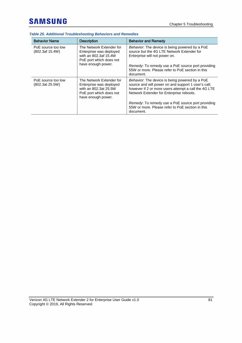
Chapter 5 Troubleshooting
Verizon 4G LTE Network Extender 2 for Enterprise User Guide v1.0 81 Copyright © 2019, All Rights Reserved.
Table 25. Additional Troubleshooting Behaviors and Remedies
Behavior Name Description Behavior and Remedy PoE source too low (802.3af 15.4W)
The Network Extender for Enterprise was deployed with an 802.3af 15.4W PoE port which does not have enough power.
Behavior: The device is being powered by a PoE source but the 4G LTE Network Extender for Enterprise will not power on. Remedy: To remedy use a PoE source port providing 55W or more. Please refer to PoE section in this document.
PoE source too low (802.3at 25.5W)
The Network Extender for Enterprise was deployed with an 802.3at 25.5W PoE port which does not have enough power.
Behavior: The device is being powered by a PoE source and will power on and support 1 user’s call; however if 2 or more users attempt a call the 4G LTE Network Extender for Enterprise reboots. Remedy: To remedy use a PoE source port providing 55W or more. Please refer to PoE section in this document.
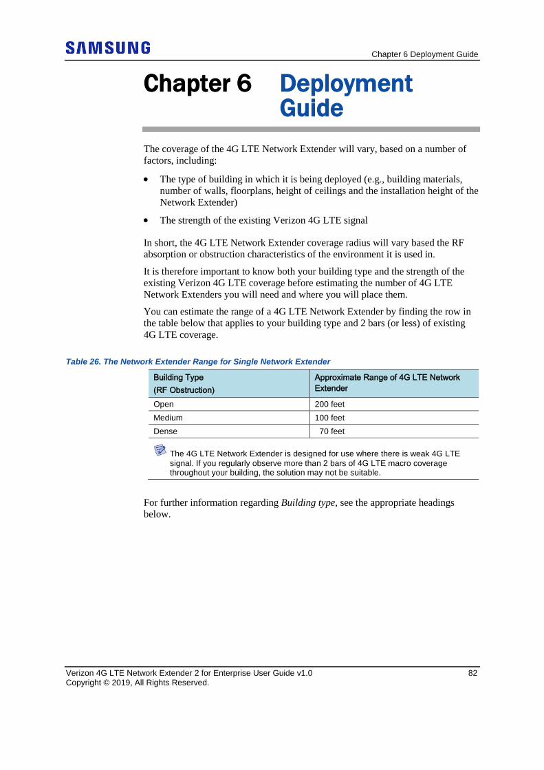
Chapter 6 Deployment Guide
Verizon 4G LTE Network Extender 2 for Enterprise User Guide v1.0 82 Copyright © 2019, All Rights Reserved.
Chapter 6 Deployment Guide
The coverage of the 4G LTE Network Extender will vary, based on a number of factors, including:
• The type of building in which it is being deployed (e.g., building materials, number of walls, floorplans, height of ceilings and the installation height of the Network Extender)
• The strength of the existing Verizon 4G LTE signal
In short, the 4G LTE Network Extender coverage radius will vary based the RF absorption or obstruction characteristics of the environment it is used in.
It is therefore important to know both your building type and the strength of the existing Verizon 4G LTE coverage before estimating the number of 4G LTE Network Extenders you will need and where you will place them.
You can estimate the range of a 4G LTE Network Extender by finding the row in the table below that applies to your building type and 2 bars (or less) of existing 4G LTE coverage.
Table 26. The Network Extender Range for Single Network Extender
Building Type (RF Obstruction)
Approximate Range of 4G LTE Network Extender
Open 200 feet Medium 100 feet Dense 70 feet
The 4G LTE Network Extender is designed for use where there is weak 4G LTE signal. If you regularly observe more than 2 bars of 4G LTE macro coverage throughout your building, the solution may not be suitable.
For further information regarding Building type, see the appropriate headings below.
Chapter 6 Deployment Guide
Verizon 4G LTE Network Extender 2 for Enterprise User Guide v1.0 83 Copyright © 2019, All Rights Reserved.
Building Type
Building type refers to the type of building in which the 4G LTE Network Extenders are being installed. There are three classifications:
• Open: An open, generally commercial building with limited amounts of clutter and no or very few internal walls. Examples are warehouses or supermarkets with high ceilings and low racks.
• Medium: A building with typical levels of clutter such as open or mixed plan offices. Some internal walls, but not regular internal walls. Examples include mixed use office space with low to mid height cubical walls.
• Dense: Regular internal walls and high levels of clutter. Examples include hospitals and schools or buildings with complex floor plans and narrow hallways and passages.
If your building has many internal concrete or metal walls, then a 4G LTE Network Extender may not be suitable for you or you may require professional assistance for installation.
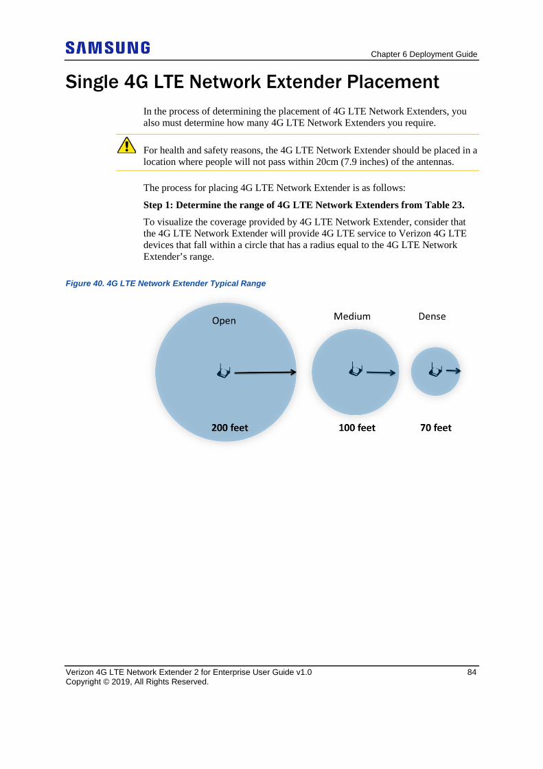
Chapter 6 Deployment Guide
Verizon 4G LTE Network Extender 2 for Enterprise User Guide v1.0 84 Copyright © 2019, All Rights Reserved.
Single 4G LTE Network Extender Placement In the process of determining the placement of 4G LTE Network Extenders, you also must determine how many 4G LTE Network Extenders you require.
For health and safety reasons, the 4G LTE Network Extender should be placed in a location where people will not pass within 20cm (7.9 inches) of the antennas.
The process for placing 4G LTE Network Extender is as follows:
Step 1: Determine the range of 4G LTE Network Extenders from Table 23.
To visualize the coverage provided by 4G LTE Network Extender, consider that the 4G LTE Network Extender will provide 4G LTE service to Verizon 4G LTE devices that fall within a circle that has a radius equal to the 4G LTE Network Extender’s range.
Figure 40. 4G LTE Network Extender Typical Range
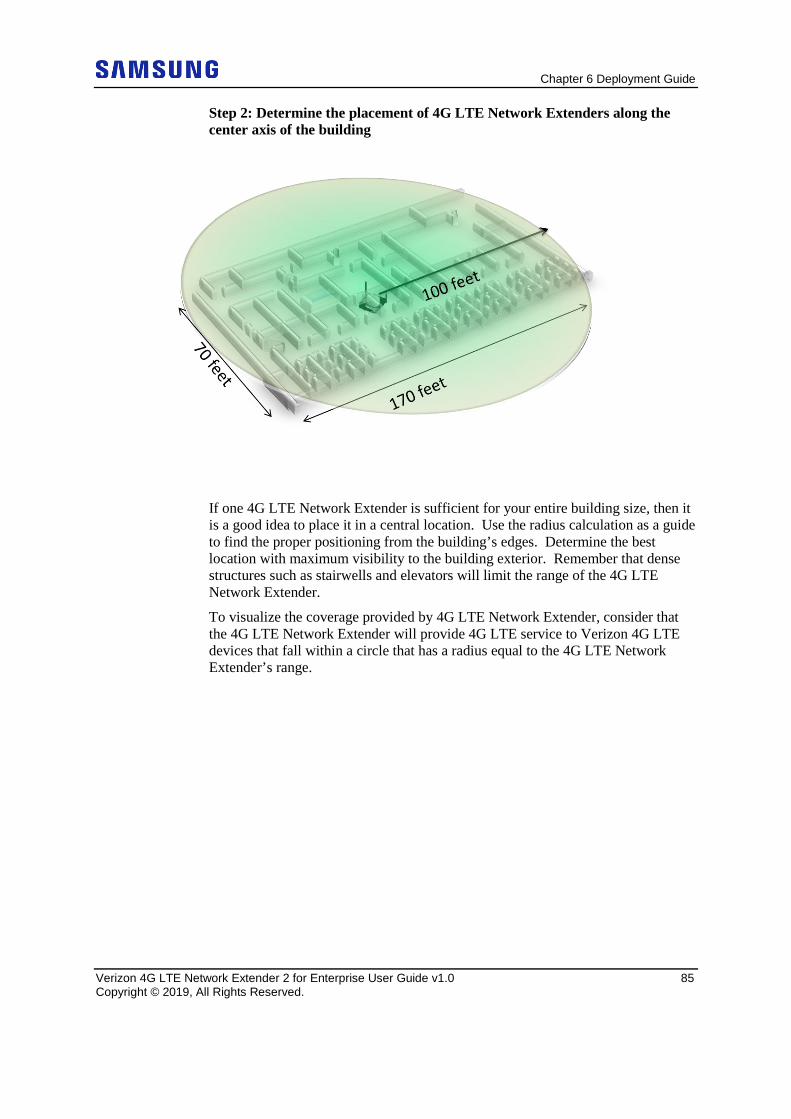
Chapter 6 Deployment Guide
Verizon 4G LTE Network Extender 2 for Enterprise User Guide v1.0 85 Copyright © 2019, All Rights Reserved.
Step 2: Determine the placement of 4G LTE Network Extenders along the center axis of the building
If one 4G LTE Network Extender is sufficient for your entire building size, then it is a good idea to place it in a central location. Use the radius calculation as a guide to find the proper positioning from the building’s edges. Determine the best location with maximum visibility to the building exterior. Remember that dense structures such as stairwells and elevators will limit the range of the 4G LTE Network Extender.
To visualize the coverage provided by 4G LTE Network Extender, consider that the 4G LTE Network Extender will provide 4G LTE service to Verizon 4G LTE devices that fall within a circle that has a radius equal to the 4G LTE Network Extender’s range.
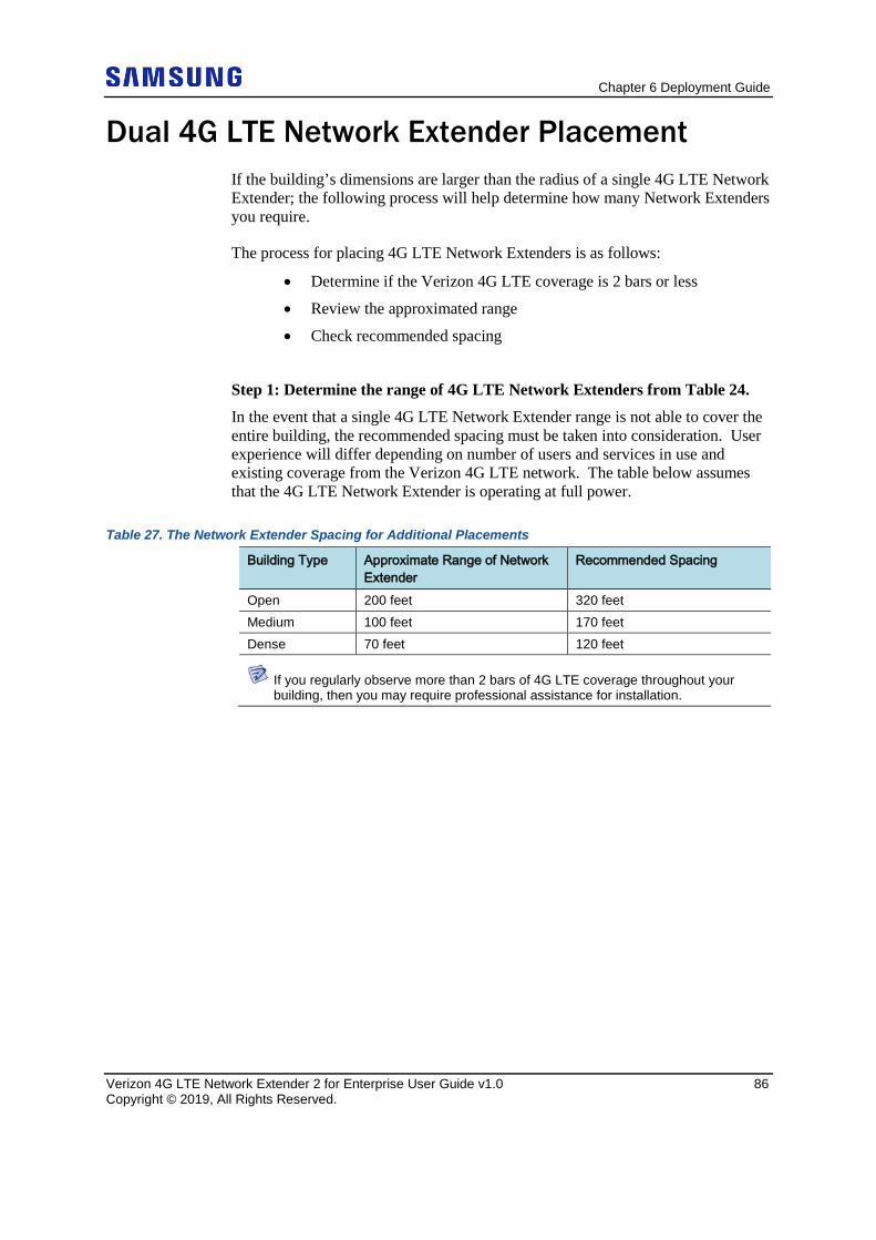
Chapter 6 Deployment Guide
Verizon 4G LTE Network Extender 2 for Enterprise User Guide v1.0 86 Copyright © 2019, All Rights Reserved.
Dual 4G LTE Network Extender Placement If the building’s dimensions are larger than the radius of a single 4G LTE Network Extender; the following process will help determine how many Network Extenders you require.
The process for placing 4G LTE Network Extenders is as follows:
• Determine if the Verizon 4G LTE coverage is 2 bars or less
• Review the approximated range
• Check recommended spacing
Step 1: Determine the range of 4G LTE Network Extenders from Table 24.
In the event that a single 4G LTE Network Extender range is not able to cover the entire building, the recommended spacing must be taken into consideration. User experience will differ depending on number of users and services in use and existing coverage from the Verizon 4G LTE network. The table below assumes that the 4G LTE Network Extender is operating at full power.
Table 27. The Network Extender Spacing for Additional Placements
Building Type Approximate Range of Network Extender
Recommended Spacing
Open 200 feet 320 feet Medium 100 feet 170 feet Dense 70 feet 120 feet
If you regularly observe more than 2 bars of 4G LTE coverage throughout your building, then you may require professional assistance for installation.
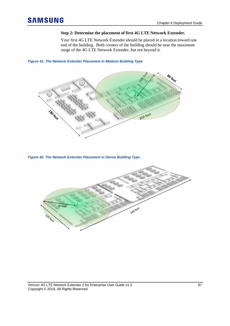
Chapter 6 Deployment Guide
Verizon 4G LTE Network Extender 2 for Enterprise User Guide v1.0 87 Copyright © 2019, All Rights Reserved.
Step 2: Determine the placement of first 4G LTE Network Extender.
Your first 4G LTE Network Extender should be placed in a location toward one end of the building. Both corners of the building should be near the maximum range of the 4G LTE Network Extender, but not beyond it.
Figure 41. The Network Extender Placement in Medium Building Type
Figure 42. The Network Extender Placement in Dense Building Type
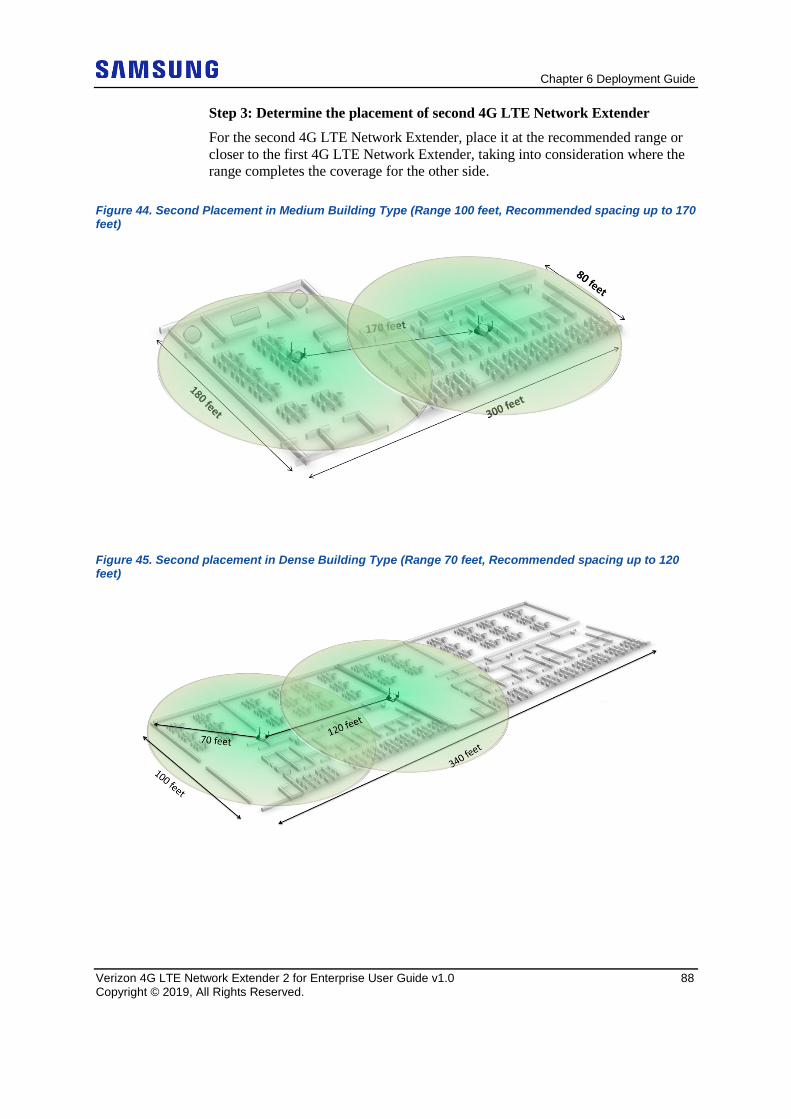
Chapter 6 Deployment Guide
Verizon 4G LTE Network Extender 2 for Enterprise User Guide v1.0 88 Copyright © 2019, All Rights Reserved.
Step 3: Determine the placement of second 4G LTE Network Extender
For the second 4G LTE Network Extender, place it at the recommended range or closer to the first 4G LTE Network Extender, taking into consideration where the range completes the coverage for the other side.
Figure 44. Second Placement in Medium Building Type (Range 100 feet, Recommended spacing up to 170 feet)
Figure 45. Second placement in Dense Building Type (Range 70 feet, Recommended spacing up to 120 feet)
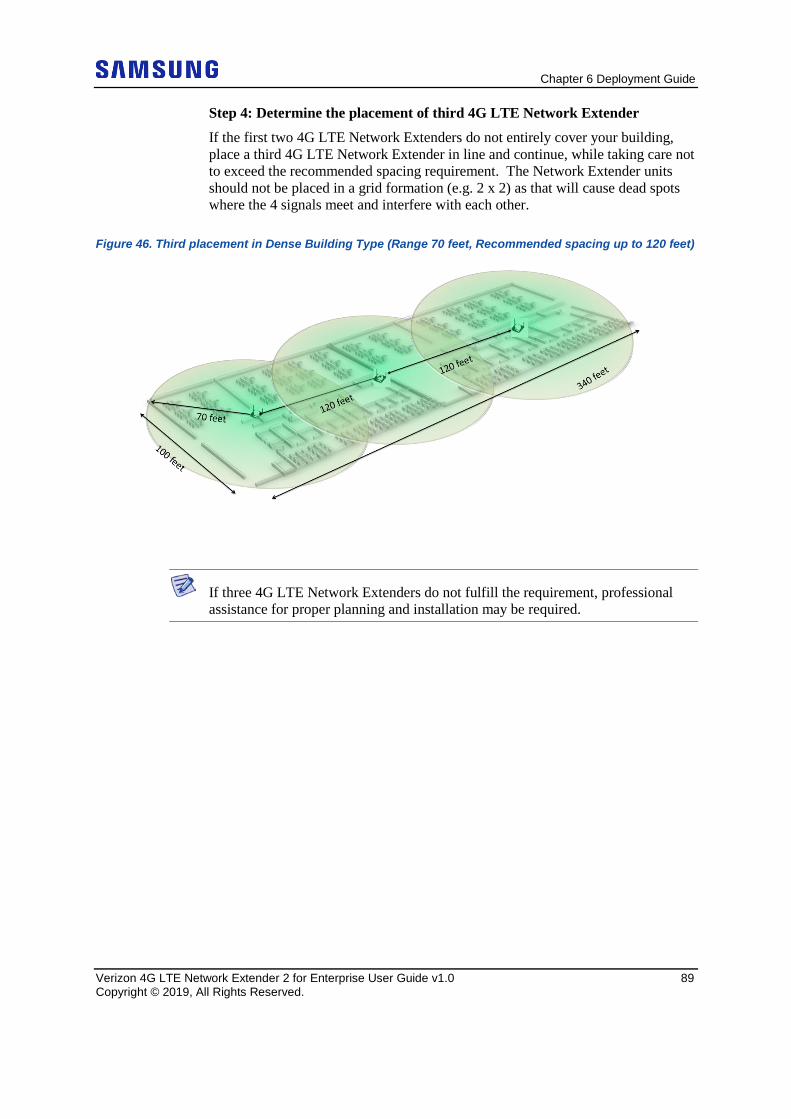
Chapter 6 Deployment Guide
Verizon 4G LTE Network Extender 2 for Enterprise User Guide v1.0 89 Copyright © 2019, All Rights Reserved.
Step 4: Determine the placement of third 4G LTE Network Extender
If the first two 4G LTE Network Extenders do not entirely cover your building, place a third 4G LTE Network Extender in line and continue, while taking care not to exceed the recommended spacing requirement. The Network Extender units should not be placed in a grid formation (e.g. 2 x 2) as that will cause dead spots where the 4 signals meet and interfere with each other.
Figure 46. Third placement in Dense Building Type (Range 70 feet, Recommended spacing up to 120 feet)
If three 4G LTE Network Extenders do not fulfill the requirement, professional assistance for proper planning and installation may be required.
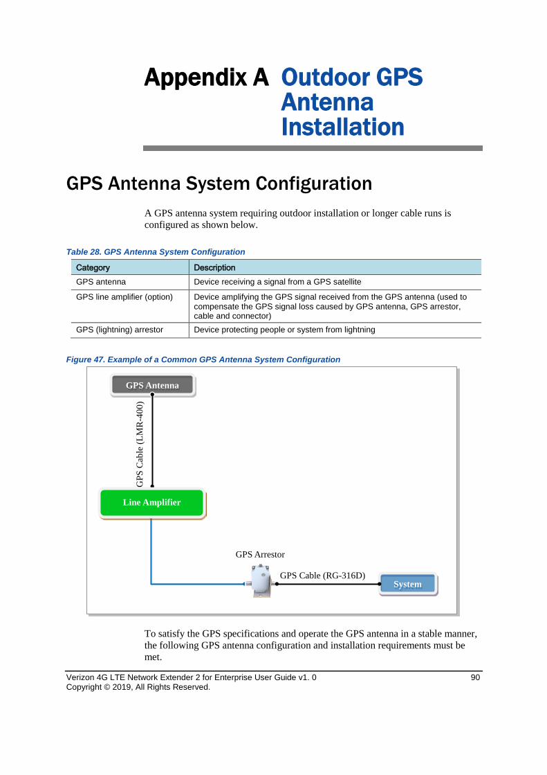
Verizon 4G LTE Network Extender 2 for Enterprise User Guide v1. 0 90 Copyright © 2019, All Rights Reserved.
Appendix A Outdoor GPS Antenna Installation
GPS Antenna System Configuration A GPS antenna system requiring outdoor installation or longer cable runs is configured as shown below.
Table 28. GPS Antenna System Configuration
Category Description GPS antenna Device receiving a signal from a GPS satellite
GPS line amplifier (option) Device amplifying the GPS signal received from the GPS antenna (used to compensate the GPS signal loss caused by GPS antenna, GPS arrestor, cable and connector)
GPS (lightning) arrestor Device protecting people or system from lightning
Figure 47. Example of a Common GPS Antenna System Configuration
To satisfy the GPS specifications and operate the GPS antenna in a stable manner, the following GPS antenna configuration and installation requirements must be met.
System
GPS Antenna
GPS
Cab
le (L
MR
-400
)
GPS Cable (RG-316D)
Line Amplifier
GPS Arrestor
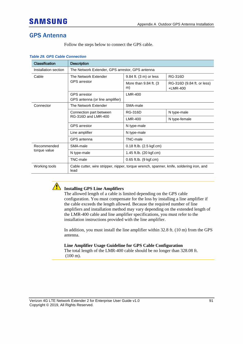
Appendix A Outdoor GPS Antenna Installation
Verizon 4G LTE Network Extender 2 for Enterprise User Guide v1.0 91 Copyright © 2019, All Rights Reserved.
GPS Antenna Follow the steps below to connect the GPS cable.
Table 29. GPS Cable Connection
Classification Description Installation section The Network Extender, GPS arrestor, GPS antenna
Cable The Network Extender GPS arrestor
9.84 ft. (3 m) or less RG-316D
More than 9.84 ft. (3 m)
RG-316D (9.84 ft. or less) +LMR-400
GPS arrestor GPS antenna (or line amplifier)
LMR-400
Connector The Network Extender SMA-male
Connection part between RG-316D and LMR-400
RG-316D N type-male
LMR-400 N type-female
GPS arrestor N type-male
Line amplifier N type-male
GPS antenna TNC-male
Recommended torque value
SMA-male 0.18 ft.lb. (2.5 kgf.cm)
N type-male 1.45 ft.lb. (20 kgf.cm)
TNC-male 0.65 ft.lb. (9 kgf.cm)
Working tools Cable cutter, wire stripper, nipper, torque wrench, spanner, knife, soldering iron, and lead
Installing GPS Line Amplifiers The allowed length of a cable is limited depending on the GPS cable configuration. You must compensate for the loss by installing a line amplifier if the cable exceeds the length allowed. Because the required number of line amplifiers and installation method may vary depending on the extended length of the LMR-400 cable and line amplifier specifications, you must refer to the installation instructions provided with the line amplifier. In addition, you must install the line amplifier within 32.8 ft. (10 m) from the GPS antenna. Line Amplifier Usage Guideline for GPS Cable Configuration The total length of the LMR-400 cable should be no longer than 328.08 ft. (100 m).
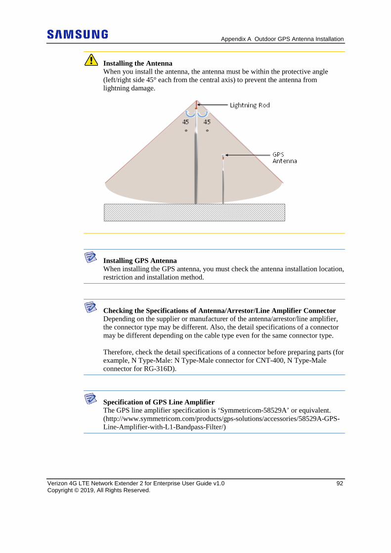
Appendix A Outdoor GPS Antenna Installation
Verizon 4G LTE Network Extender 2 for Enterprise User Guide v1.0 92 Copyright © 2019, All Rights Reserved.
Installing the Antenna When you install the antenna, the antenna must be within the protective angle (left/right side 45° each from the central axis) to prevent the antenna from lightning damage.
Installing GPS Antenna When installing the GPS antenna, you must check the antenna installation location, restriction and installation method.
Checking the Specifications of Antenna/Arrestor/Line Amplifier Connector Depending on the supplier or manufacturer of the antenna/arrestor/line amplifier, the connector type may be different. Also, the detail specifications of a connector may be different depending on the cable type even for the same connector type. Therefore, check the detail specifications of a connector before preparing parts (for example, N Type-Male: N Type-Male connector for CNT-400, N Type-Male connector for RG-316D).
Specification of GPS Line Amplifier The GPS line amplifier specification is ‘Symmetricom-58529A’ or equivalent. (http://www.symmetricom.com/products/gps-solutions/accessories/58529A-GPS-Line-Amplifier-with-L1-Bandpass-Filter/)
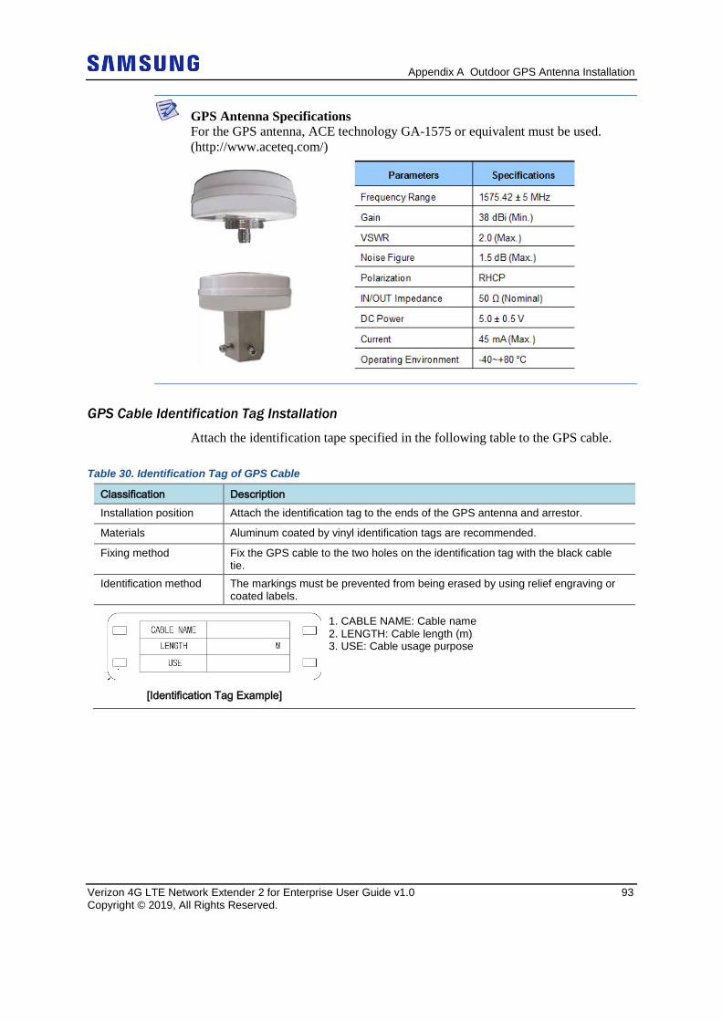
Appendix A Outdoor GPS Antenna Installation
Verizon 4G LTE Network Extender 2 for Enterprise User Guide v1.0 93 Copyright © 2019, All Rights Reserved.
GPS Antenna Specifications For the GPS antenna, ACE technology GA-1575 or equivalent must be used. (http://www.aceteq.com/)
GPS Cable Identification Tag Installation
Attach the identification tape specified in the following table to the GPS cable.
Table 30. Identification Tag of GPS Cable
Classification Description Installation position Attach the identification tag to the ends of the GPS antenna and arrestor.
Materials Aluminum coated by vinyl identification tags are recommended.
Fixing method Fix the GPS cable to the two holes on the identification tag with the black cable tie.
Identification method The markings must be prevented from being erased by using relief engraving or coated labels.
[Identification Tag Example]
1. CABLE NAME: Cable name 2. LENGTH: Cable length (m) 3. USE: Cable usage purpose
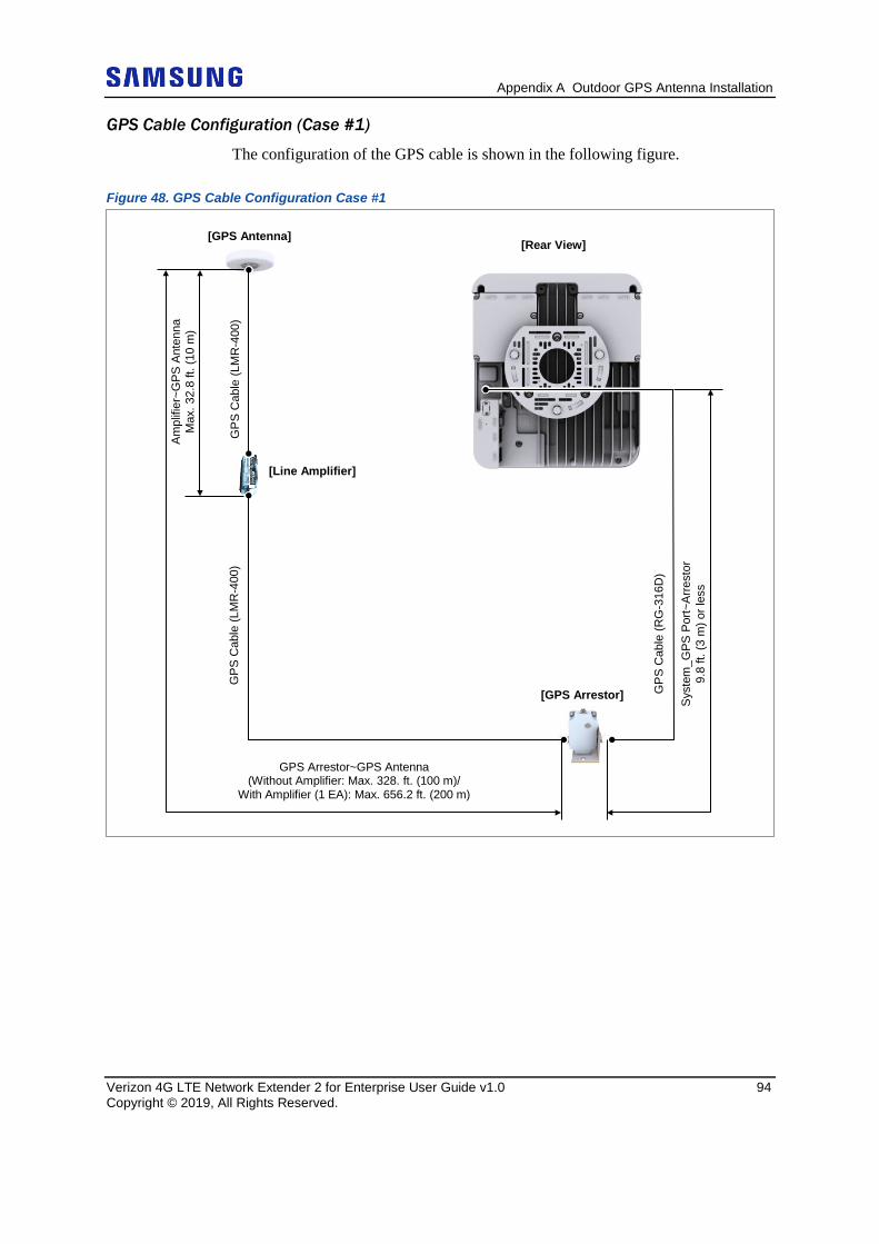
Appendix A Outdoor GPS Antenna Installation
Verizon 4G LTE Network Extender 2 for Enterprise User Guide v1.0 94 Copyright © 2019, All Rights Reserved.
GPS Cable Configuration (Case #1)
The configuration of the GPS cable is shown in the following figure.
Figure 48. GPS Cable Configuration Case #1
[Rear View] G
PS C
able
(LM
R-4
00)
[Line Amplifier]
GPS
Cab
le (L
MR
-400
)
GPS Arrestor~GPS Antenna (Without Amplifier: Max. 328. ft. (100 m)/
With Amplifier (1 EA): Max. 656.2 ft. (200 m)
Ampl
ifier
~GPS
Ant
enna
M
ax. 3
2.8
ft. (1
0 m
)
[GPS Antenna]
[GPS Arrestor] GPS
Cab
le (R
G-3
16D
)
Syst
em_G
PS P
ort~
Arre
stor
9.
8 ft.
(3 m
) or l
ess
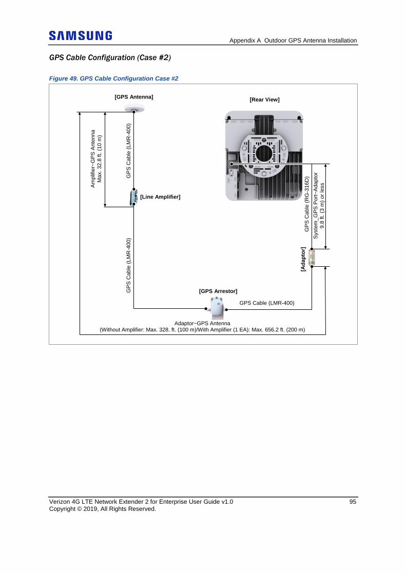
Appendix A Outdoor GPS Antenna Installation
Verizon 4G LTE Network Extender 2 for Enterprise User Guide v1.0 95 Copyright © 2019, All Rights Reserved.
GPS Cable Configuration (Case #2)
Figure 49. GPS Cable Configuration Case #2
Adaptor~GPS Antenna (Without Amplifier: Max. 328. ft. (100 m)/With Amplifier (1 EA): Max. 656.2 ft. (200 m)
Ampl
ifier
~GPS
Ant
enna
M
ax. 3
2.8
ft. (1
0 m
) [GPS Antenna] [Rear View]
GPS
Cab
le (L
MR
-400
)
[Line Amplifier]
GPS
Cab
le (L
MR
-400
)
[GPS Arrestor]
Syst
em_G
PS P
ort~
Adap
tor
9.8
ft. (3
m) o
r les
s
[Ada
ptor
] GPS Cable (LMR-400)
GPS
Cab
le (R
G-3
16D
)
Appendix A Outdoor GPS Antenna Installation
Verizon 4G LTE Network Extender 2 for Enterprise User Guide v1.0 96 Copyright © 2019, All Rights Reserved.
GPS Cable Length The length of the GPS cable is limited for each section as shown below. 1. The Network Extender GPS arrestor: 9.84 ft. (3 m) or less If the distance between the Network Extender and the GPS arrestor is longer than 9.84 ft. (3 m), use the straight adapter for extension. Connect the RG-316D cable up to 9.84 ft. (3 m) to the straight adapter and then extend the connection to the GPS arrestor using the LMR-400 cable. 2. RG-316D~GPS arrestor GPS antenna (LMR-400 cable installation section) - Total length of the LMR-400 cable: 328.08 ft. (100 m) or less - If the total length of the LMR-400 cable is longer than 328.08 ft. (100 m), compensate the loss by installing a line amplifier. Because the required number of line amplifiers and installation method may vary, depending on the extended length of the LMR-400 cable and line amplifier specifications, you must refer to the installation instructions provided with the line amplifier. In addition, you must install the line amplifier within 32.8 ft. (10 m) from the GPS antenna. For example, when using a line amplifier (Symmetricom-58529A) × 1 EA → Total length of the LMR-400 cable: 656.17 ft. (200 m) or less.
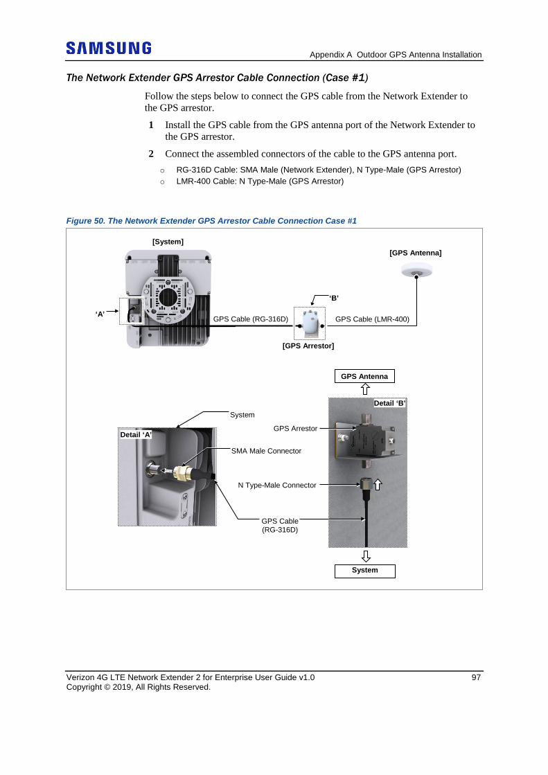
Appendix A Outdoor GPS Antenna Installation
Verizon 4G LTE Network Extender 2 for Enterprise User Guide v1.0 97 Copyright © 2019, All Rights Reserved.
The Network Extender GPS Arrestor Cable Connection (Case #1)
Follow the steps below to connect the GPS cable from the Network Extender to the GPS arrestor.
1 Install the GPS cable from the GPS antenna port of the Network Extender to the GPS arrestor.
2 Connect the assembled connectors of the cable to the GPS antenna port. o RG-316D Cable: SMA Male (Network Extender), N Type-Male (GPS Arrestor) o LMR-400 Cable: N Type-Male (GPS Arrestor)
Figure 50. The Network Extender GPS Arrestor Cable Connection Case #1
‘B’
[GPS Arrestor]
[GPS Antenna] [System]
GPS Cable (RG-316D)
System
SMA Male Connector
GPS Cable (RG-316D)
Detail ‘B’
N Type-Male Connector
GPS Arrestor
System
GPS Antenna
‘A’ GPS Cable (LMR-400)
Detail ‘A’
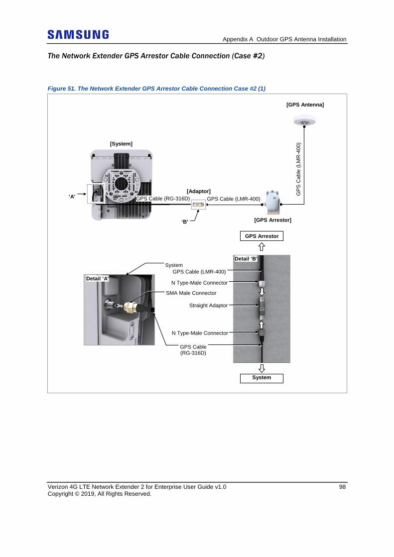
Appendix A Outdoor GPS Antenna Installation
Verizon 4G LTE Network Extender 2 for Enterprise User Guide v1.0 98 Copyright © 2019, All Rights Reserved.
The Network Extender GPS Arrestor Cable Connection (Case #2)
Figure 51. The Network Extender GPS Arrestor Cable Connection Case #2 (1)
Detail ‘B’
Straight Adaptor
[System]
‘A’
[GPS Arrestor]
[GPS Antenna]
GPS Cable (LMR-400)
‘B’
GPS
Cab
le (L
MR
-400
)
[Adaptor] GPS Cable (RG-316D)
System
SMA Male Connector
GPS Cable (RG-316D)
N Type-Male Connector
GPS Cable (LMR-400) System
GPS Arrestor
Detail ‘A’ N Type-Male Connector
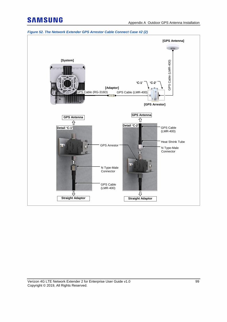
Appendix A Outdoor GPS Antenna Installation
Verizon 4G LTE Network Extender 2 for Enterprise User Guide v1.0 99 Copyright © 2019, All Rights Reserved.
Figure 52. The Network Extender GPS Arrestor Cable Connect Case #2 (2)
[System]
‘C-1’
[GPS Arrestor]
[GPS Antenna]
GPS Cable (LMR-400)
GPS
Cab
le (L
MR
-400
)
‘C-2’ [Adaptor]
GPS Cable (RG-316D)
Detail ‘C-1’
GPS Antenna
Straight Adaptor
Detail ‘C-2’
N Type-Male Connector
GPS Cable (LMR-400)
Heat Shrink Tube
GPS Antenna
Straight Adaptor
GPS Arrestor
N Type-Male Connector
GPS Cable (LMR-400)
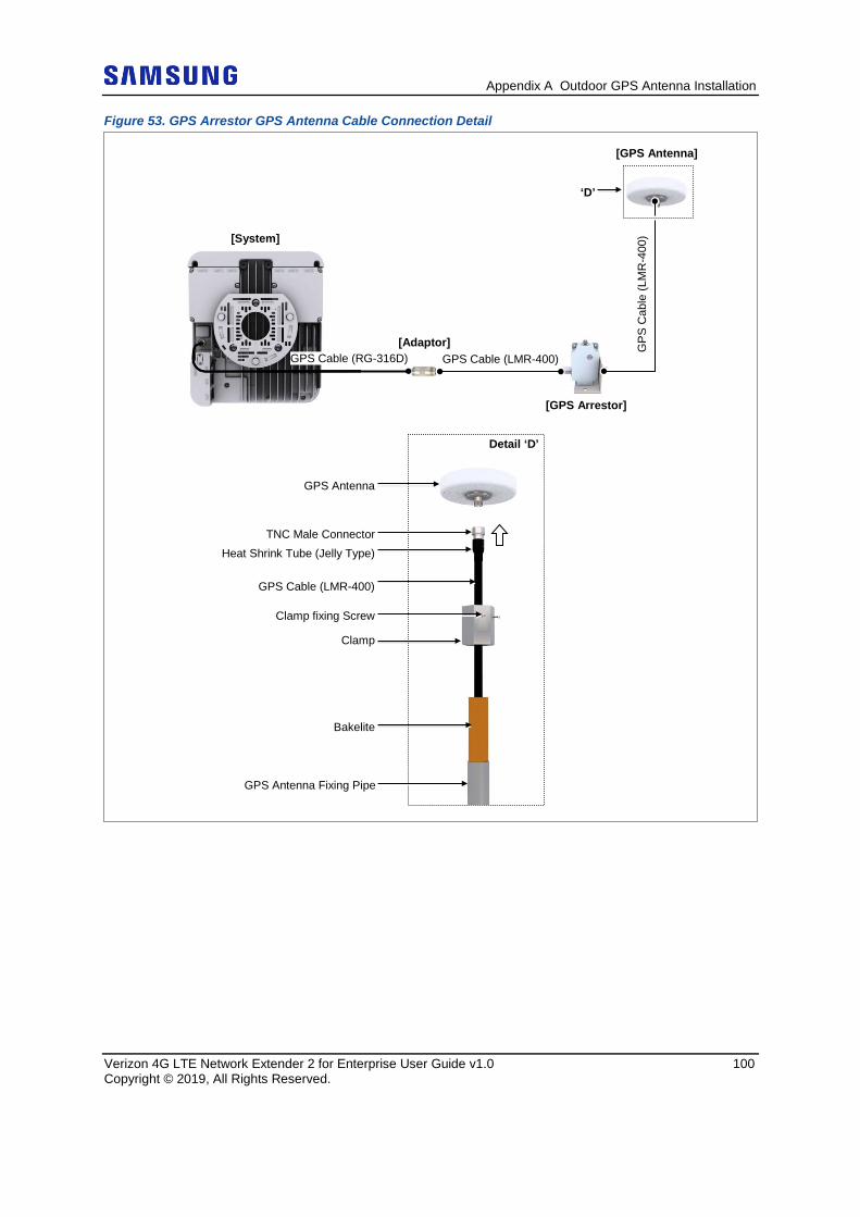
Appendix A Outdoor GPS Antenna Installation
Verizon 4G LTE Network Extender 2 for Enterprise User Guide v1.0 100 Copyright © 2019, All Rights Reserved.
Figure 53. GPS Arrestor GPS Antenna Cable Connection Detail
[System]
[GPS Arrestor]
[GPS Antenna]
GPS Cable (LMR-400)
GPS
Cab
le (L
MR
-400
)
‘D’
[Adaptor] GPS Cable (RG-316D)
GPS Cable (LMR-400)
GPS Antenna
Clamp
Clamp fixing Screw
Bakelite
GPS Antenna Fixing Pipe
TNC Male Connector Heat Shrink Tube (Jelly Type)
Detail ‘D’
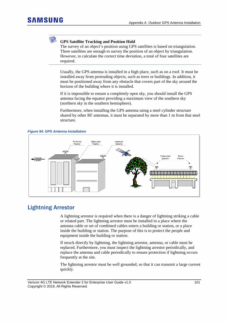
Appendix A Outdoor GPS Antenna Installation
Verizon 4G LTE Network Extender 2 for Enterprise User Guide v1.0 101 Copyright © 2019, All Rights Reserved.
GPS Satellite Tracking and Position Hold The survey of an object’s position using GPS satellites is based on triangulation. Three satellites are enough to survey the position of an object by triangulation. However, to calculate the correct time deviation, a total of four satellites are required.
Usually, the GPS antenna is installed in a high place, such as on a roof. It must be installed away from protruding objects, such as trees or buildings. In addition, it must be positioned away from any obstacle that covers part of the sky around the horizon of the building where it is installed.
If it is impossible to ensure a completely open sky, you should install the GPS antenna facing the equator providing a maximum view of the southern sky (northern sky in the southern hemisphere).
Furthermore, when installing the GPS antenna using a steel cylinder structure shared by other RF antennas, it must be separated by more than 1 m from that steel structure.
Figure 54. GPS Antenna Installation
Lightning Arrestor A lightning arrestor is required when there is a danger of lightning striking a cable or related part. The lightning arrestor must be installed in a place where the antenna cable or set of combined cables enters a building or station, or a place inside the building or station. The purpose of this is to protect the people and equipment inside the building or station.
If struck directly by lightning, the lightning arrestor, antenna, or cable must be replaced. Furthermore, you must inspect the lightning arrestor periodically, and replace the antenna and cable periodically to ensure protection if lightning occurs frequently at the site.
The lightning arrestor must be well grounded, so that it can transmit a large current quickly.
Appendix A Outdoor GPS Antenna Installation
Verizon 4G LTE Network Extender 2 for Enterprise User Guide v1.0 102 Copyright © 2019, All Rights Reserved.
Signal Interference The GPS system is designed so that it has a strong immunity to noise and can endure interference.
The Samsung GPS receiver provides a quality timing clock in most installations.
However, to ensure that the GPS receiver performs locking successfully and guarantees uninterrupted timing performance, an interference-free environment is required for frequencies near the GPS L1 frequency (1575.42 ± 1 MHz).
Interference Types There are two types of interference which affect the GPS L1 frequency:
• Narrowband (inband) interference When a frequency deviation (3.5 kHz), such as an FM wave, inflows in around the GPS L1 frequency (1575.42 MHz), it is called narrow band (inband) interference. Narrowband interference is monitored by the spectrum analyzer. Because it has a time lag, a locking failure or a different type of alarm can occur.
• Wideband interference When around the GPS L1 frequency (1575.42 MHz) and the frequency deviation is more than 7 kHz, this is called wide band interference. Wideband interference includes the interference induced by the harmonics from a communication service with a different frequency bandwidth, increased thermal noise from communication services around the L1 band, inflow of interference due to unauthorized communication, saturation due to oscillation of an accessory device, and so on. You cannot monitor these kinds of interferences with a device such as a spectrum analyzer. If the system has a wideband interference problem, you should consult an expert in this area.
For other bandwidths, except the GPS L1 frequency (1575.42 ± 1 MHz), a GPS Band Pass Filter (BPF) must be included within the GPS antenna to remove the interference from the GPS bandwidth. No outband interference must affect the GPS signals.
Appendix A Outdoor GPS Antenna Installation
Verizon 4G LTE Network Extender 2 for Enterprise User Guide v1.0 103 Copyright © 2019, All Rights Reserved.
Avoiding Interference If more than one antenna for other communications, such as an antenna for a base station or satellite communication, is installed in the surroundings, the GPS antenna must be installed in a location to which no interference signals flow in.
If interference exists within the GPS L1 frequency bandwidths (1575.42 ± 1 MHz), you should use a band pass filter to prevent them from affecting it.
Furthermore, if the GPS antenna is installed by a transmitter which operates with a bandwidth similar to the GPS L1 frequency, the possibility of interference increases (in this case, interference is caused by harmonics). If the GPS antenna has a problem due to interference, you must move it to a different location where interference signals can be avoided or minimized in strength.
Inband Noise Inband noise includes narrowband noise and wideband noise that occur in an inband width. (L1, 1575.42 ± 1 MHz) - Narrowband noise in an inband width: If it is higher than 108 dBm, it can affect the operation of the GPS receiver. - Wideband noise in an inband width: It may not be detected by a measuring instrument and impair the sensitivity of the GPS receiver, and thus affect its operation.
If there is an outband interference problem, you can reduce the effects of interference on the GPS receiver by applying one or more L1 GPS band pass filters.
The filter should be installed at the following locations:
• The input connector of the Samsung GPS receiver
• Behind the antenna or the front end of a line amplifier The filters above are used to reject jamming tones for outband signals. If interferences actually occur in the inband signals, they will result in serious consequences.
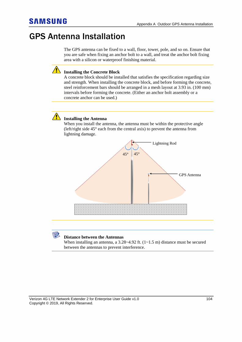
Appendix A Outdoor GPS Antenna Installation
Verizon 4G LTE Network Extender 2 for Enterprise User Guide v1.0 104 Copyright © 2019, All Rights Reserved.
GPS Antenna Installation The GPS antenna can be fixed to a wall, floor, tower, pole, and so on. Ensure that you are safe when fixing an anchor bolt to a wall, and treat the anchor bolt fixing area with a silicon or waterproof finishing material.
Installing the Concrete Block A concrete block should be installed that satisfies the specification regarding size and strength. When installing the concrete block, and before forming the concrete, steel reinforcement bars should be arranged in a mesh layout at 3.93 in. (100 mm) intervals before forming the concrete. (Either an anchor bolt assembly or a concrete anchor can be used.)
Installing the Antenna When you install the antenna, the antenna must be within the protective angle (left/right side 45° each from the central axis) to prevent the antenna from lightning damage.
Distance between the Antennas When installing an antenna, a 3.28~4.92 ft. (1~1.5 m) distance must be secured between the antennas to prevent interference.
Lightning Rod
45° 45°
GPS Antenna
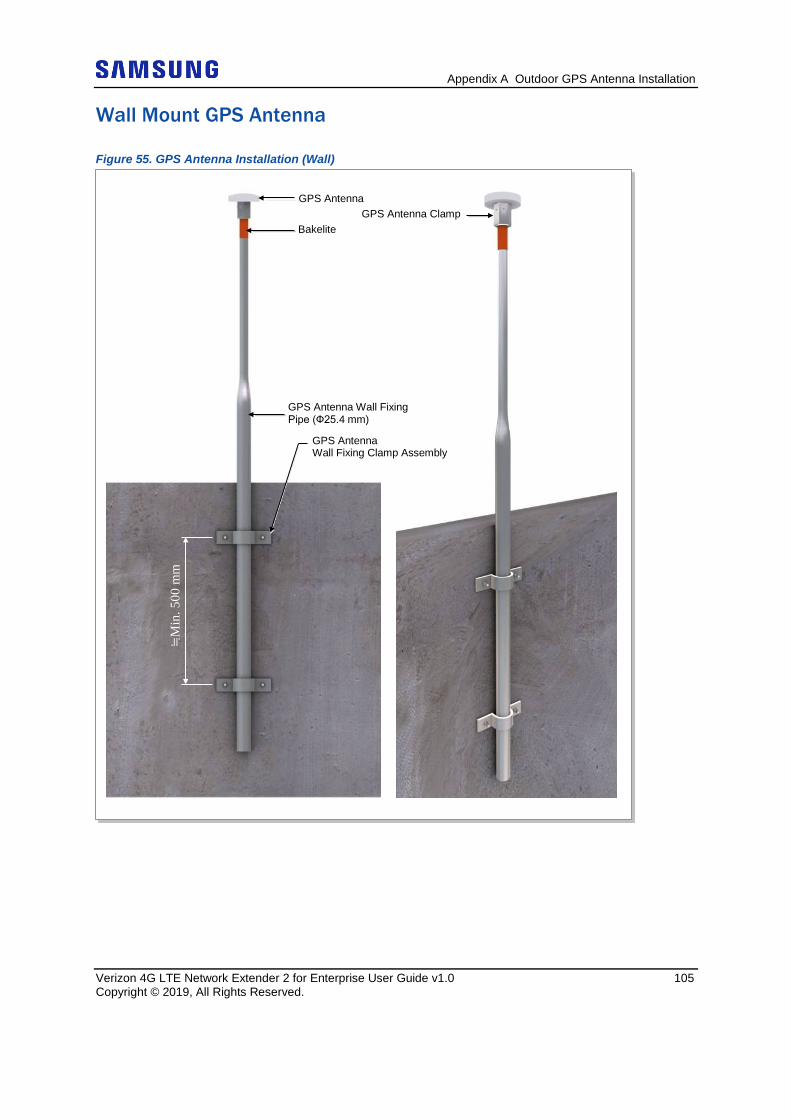
Appendix A Outdoor GPS Antenna Installation
Verizon 4G LTE Network Extender 2 for Enterprise User Guide v1.0 105 Copyright © 2019, All Rights Reserved.
Wall Mount GPS Antenna
Figure 55. GPS Antenna Installation (Wall)
GPS Antenna Wall Fixing Pipe (Ф25.4 mm)
GPS Antenna
Bakelite GPS Antenna Clamp
GPS Antenna Wall Fixing Clamp Assembly
≒M
in. 5
00 m
m
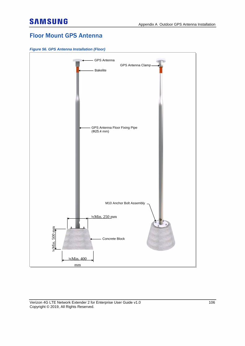
Appendix A Outdoor GPS Antenna Installation
Verizon 4G LTE Network Extender 2 for Enterprise User Guide v1.0 106 Copyright © 2019, All Rights Reserved.
Floor Mount GPS Antenna
Figure 56. GPS Antenna Installation (Floor)
GPS Antenna Floor Fixing Pipe (Ф25.4 mm)
GPS Antenna
Bakelite GPS Antenna Clamp
M10 Anchor Bolt Assembly
≒M
in. 5
00 m
m
Concrete Block
≒Min. 400 mm
≒Min. 250 mm
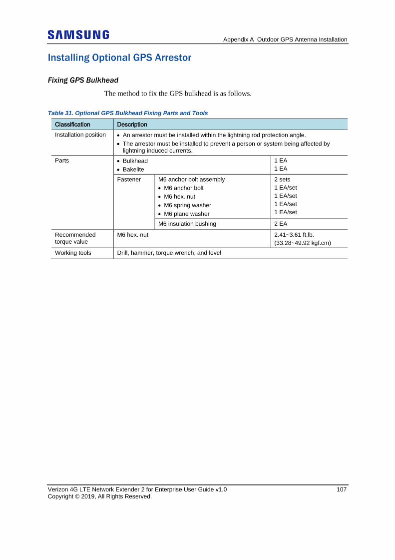
Appendix A Outdoor GPS Antenna Installation
Verizon 4G LTE Network Extender 2 for Enterprise User Guide v1.0 107 Copyright © 2019, All Rights Reserved.
Installing Optional GPS Arrestor
Fixing GPS Bulkhead
The method to fix the GPS bulkhead is as follows.
Table 31. Optional GPS Bulkhead Fixing Parts and Tools
Classification Description Installation position • An arrestor must be installed within the lightning rod protection angle.
• The arrestor must be installed to prevent a person or system being affected by lightning induced currents.
Parts • Bulkhead • Bakelite
1 EA 1 EA
Fastener M6 anchor bolt assembly • M6 anchor bolt • M6 hex. nut • M6 spring washer • M6 plane washer
2 sets 1 EA/set 1 EA/set 1 EA/set 1 EA/set
M6 insulation bushing 2 EA
Recommended torque value
M6 hex. nut 2.41~3.61 ft.lb. (33.28~49.92 kgf.cm)
Working tools Drill, hammer, torque wrench, and level
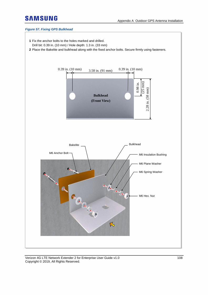
Appendix A Outdoor GPS Antenna Installation
Verizon 4G LTE Network Extender 2 for Enterprise User Guide v1.0 108 Copyright © 2019, All Rights Reserved.
Figure 57. Fixing GPS Bulkhead
1 Fix the anchor bolts to the holes marked and drilled.
Drill bit: 0.39 in. (10 mm) / Hole depth: 1.3 in. (33 mm) 2 Place the Bakelite and bulkhead along with the fixed anchor bolts. Secure firmly using fasteners.
3.58 in. (91 mm) 0.39 in. (10 mm) 0.39 in. (10 mm)
2.28
in. (
58 m
m)
0.98
in.
(25
mm
)
Bulkhead (Front View)
M6 Anchor Bolt
Bakelite Bulkhead
M6 Insulation Bushing
M6 Plane Washer
M6 Spring Washer
M6 Hex. Nut
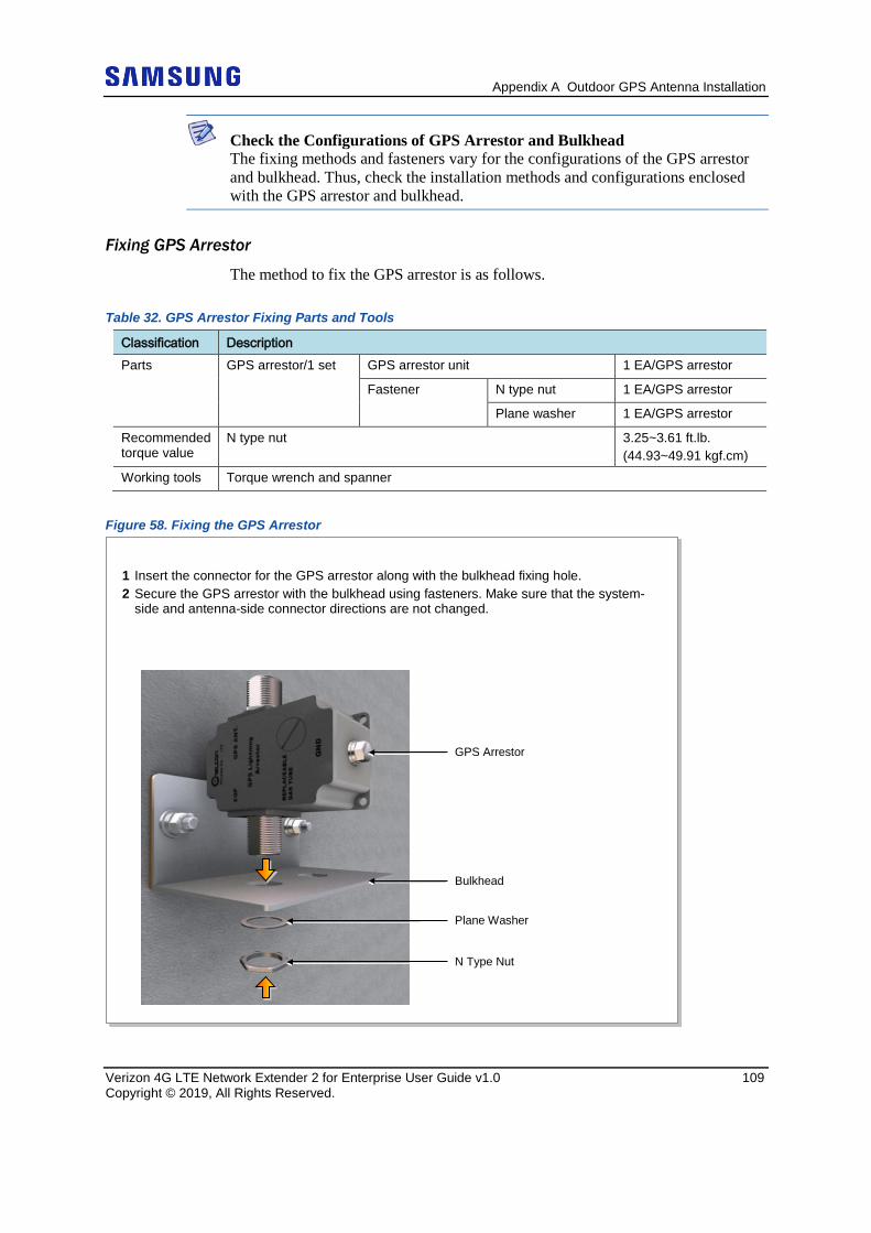
Appendix A Outdoor GPS Antenna Installation
Verizon 4G LTE Network Extender 2 for Enterprise User Guide v1.0 109 Copyright © 2019, All Rights Reserved.
Check the Configurations of GPS Arrestor and Bulkhead The fixing methods and fasteners vary for the configurations of the GPS arrestor and bulkhead. Thus, check the installation methods and configurations enclosed with the GPS arrestor and bulkhead.
Fixing GPS Arrestor
The method to fix the GPS arrestor is as follows.
Table 32. GPS Arrestor Fixing Parts and Tools
Classification Description Parts GPS arrestor/1 set GPS arrestor unit 1 EA/GPS arrestor
Fastener N type nut 1 EA/GPS arrestor
Plane washer 1 EA/GPS arrestor
Recommended torque value
N type nut 3.25~3.61 ft.lb. (44.93~49.91 kgf.cm)
Working tools Torque wrench and spanner
Figure 58. Fixing the GPS Arrestor
GPS Arrestor
Bulkhead
Plane Washer
N Type Nut
1 Insert the connector for the GPS arrestor along with the bulkhead fixing hole. 2 Secure the GPS arrestor with the bulkhead using fasteners. Make sure that the system-
side and antenna-side connector directions are not changed.
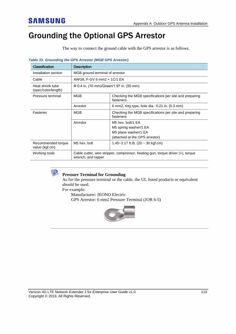
Appendix A Outdoor GPS Antenna Installation
Verizon 4G LTE Network Extender 2 for Enterprise User Guide v1.0 110 Copyright © 2019, All Rights Reserved.
Grounding the Optional GPS Arrestor The way to connect the ground cable with the GPS arrestor is as follows.
Table 33. Grounding the GPS Arrestor (MGB GPS Arrestor)
Classification Description Installation section MGB ground terminal of arrestor
Cable AWG8, F-GV 6 mm2 × 1C/1 EA
Heat shrink tube (spec/color/length)
Ф 0.4 in. (10 mm)/Green/1.97 in. (50 mm)
Pressure terminal MGB Checking the MGB specifications per site and preparing fasteners
Arrestor 6 mm2, ring type, hole dia.: 0.21 in. (5.3 mm)
Fastener MGB Checking the MGB specifications per site and preparing fasteners
Arrestor M5 hex. bolt/1 EA M5 spring washer/1 EA M5 plane washer/1 EA (attached at the GPS arrestor)
Recommended torque value (kgf.cm)
M5 hex. bolt 1.45~2.17 ft.lb. (20 ~ 30 kgf.cm)
Working tools Cable cutter, wire stripper, compressor, heating gun, torque driver (+), torque wrench, and nipper
Pressure Terminal for Grounding As for the pressure terminal or the cable, the UL listed products or equivalent should be used. For example: Manufacturer: JEONO Electric GPS Arrestor: 6 mm2 Pressure Terminal (JOR 6-5)
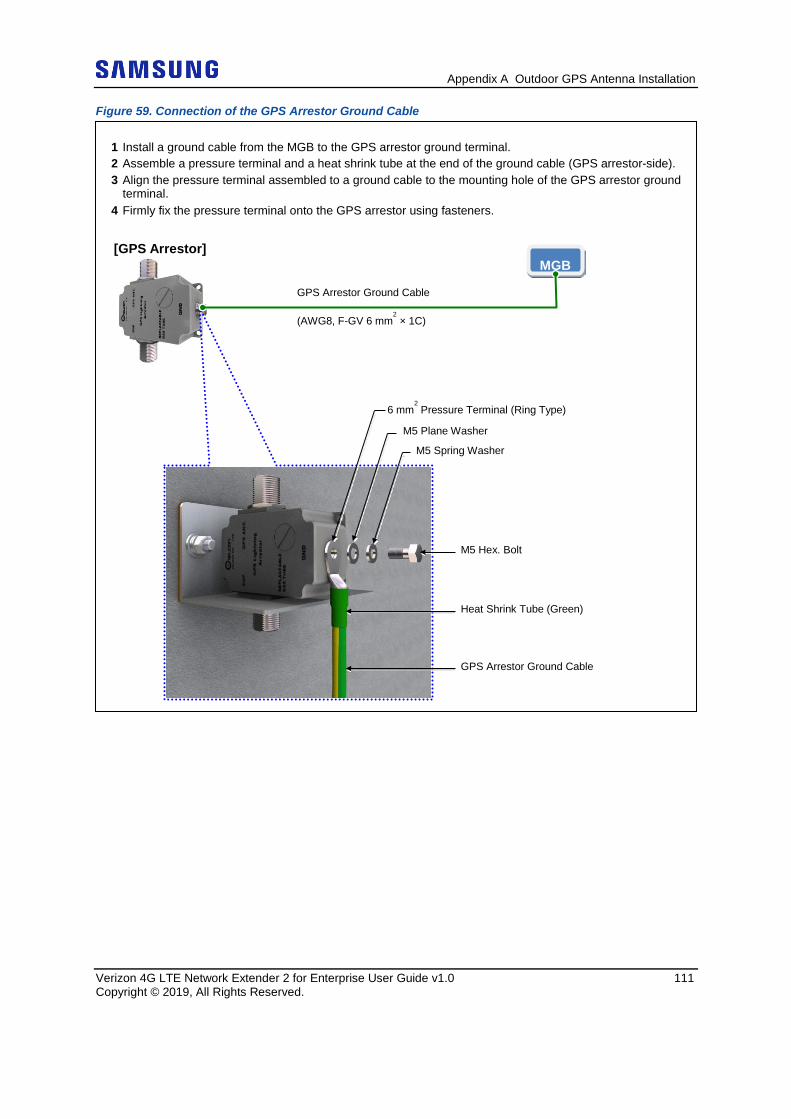
Appendix A Outdoor GPS Antenna Installation
Verizon 4G LTE Network Extender 2 for Enterprise User Guide v1.0 111 Copyright © 2019, All Rights Reserved.
Figure 59. Connection of the GPS Arrestor Ground Cable
1 Install a ground cable from the MGB to the GPS arrestor ground terminal. 2 Assemble a pressure terminal and a heat shrink tube at the end of the ground cable (GPS arrestor-side). 3 Align the pressure terminal assembled to a ground cable to the mounting hole of the GPS arrestor ground
terminal. 4 Firmly fix the pressure terminal onto the GPS arrestor using fasteners.
GPS Arrestor Ground Cable (AWG8, F-GV 6 mm
2 × 1C)
Heat Shrink Tube (Green)
GPS Arrestor Ground Cable
MGB
[GPS Arrestor]
6 mm2 Pressure Terminal (Ring Type)
M5 Plane Washer
M5 Spring Washer
M5 Hex. Bolt
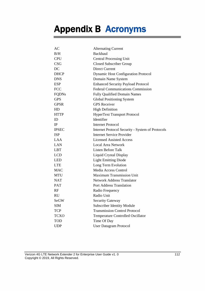
Verizon 4G LTE Network Extender 2 for Enterprise User Guide v1. 0 112 Copyright © 2019, All Rights Reserved.
Appendix B Acronyms
AC Alternating Current B/H Backhaul CPU Central Processing Unit CSG Closed Subscriber Group DC Direct Current DHCP Dynamic Host Configuration Protocol DNS Domain Name System ESP Enhanced Security Payload Protocol FCC Federal Communications Commission FQDNs Fully Qualified Domain Names GPS Global Positioning System GPSR GPS Receiver HD High Definition HTTP HyperText Transport Protocol ID Identifier IP Internet Protocol IPSEC Internet Protocol Security - System of Protocols ISP Internet Service Provider LAA Licensed Assisted Access LAN Local Area Network LBT Listen Before Talk LCD Liquid Crystal Display LED Light Emitting Diode LTE Long Term Evolution MAC Media Access Control MTU Maximum Transmission Unit NAT Network Address Translator PAT Port Address Translation RF Radio Frequency RU Radio Unit SeGW Security Gateway SIM Subscriber Identity Module TCP Transmission Control Protocol TCXO Temperature Controlled Oscillator TOD Time Of Day UDP User Datagram Protocol
Verizon 4G LTE Network Extender 2 for Enterprise User Guide Document Version 1.0 © Samsung Electronics America, Inc. All rights reserved.