Embed Size (px)
Citation preview
Uncontrolled Copy when printed or downloaded. Please refer to the 4D Systems website for the latest Revision of this document
4DPi-32
3.2” Primary Display for the Raspberry Pi
Document Date: 13th August 2014
Document Revision: 1.1 DATA
SH
EET

4DPi-3
2 P
rimary
Dis
pla
y –
Rasp
ber
ry P
i
Contents
1. Description ............................................................................................................................. 3
2. Features ................................................................................................................................. 3
3. Pin Configuration and Summary .............................................................................................. 4
4. Connecting the Display to the Pi .............................................................................................. 6
Hardware Connection ............................................................................................................................ 6 4.1.
Software Download / Installation .......................................................................................................... 6 4.2.
Calibrating the Touch Screen ................................................................................................................. 7 4.3.
Change the Display Orientation ............................................................................................................. 8 4.4.
Change the SPI Freq and Compression .................................................................................................. 8 4.5.
Backlight Control .................................................................................................................................... 8 4.6.
Parameters Listing .................................................................................................................................. 9 4.7.
5. Notes ................................................................................................................................... 10
6. Scribble Box .......................................................................................................................... 10
7. Mechanical Details ............................................................................................................... 11
8. Schematic Diagram ............................................................................................................... 12
9. Specifications and Ratings ..................................................................................................... 13
10. Legal Notice ........................................................................................................................ 14
11. Contact Information............................................................................................................ 14

4D SYSTEMS 4DPi-32 Primary Display – Raspberry Pi Compatible
© 2014 4D SYSTEMS Page 3 of 14 www.4dsystems.com.au
4DPi-3
2 P
rimary
Dis
pla
y –
Rasp
ber
ry P
i
1. Description The 4DPi-32 is a 3.2” Primary Display for the Raspberry Pi*, which plugs directly on top and displays the primary output like what is normally sent to the HDMI or Composite output. It features an integrated Resistive Touch panel, enabling the 4DPi-32 to function with the Raspberry Pi without the need for a mouse. Communication between the 4DPi-32 and the Raspberry Pi is interfaced with a high speed 48Mhz SPI connection, which utilises an on-board processor for direct command interpretation and SPI communication compression, and features a customised DMA enabled kernel. This combination allows this display to output 25FPS when displaying a typical image/video, and can achieve higher depending if the image can be compressed. The 4DPi-32 is designed to work with the Raspbian Operating System running on the Raspberry Pi, as that is the official Raspberry Pi operating system. The 4DPi-32 features a breakout header (P2), which enables all of the Raspberry Pi GPIO pins to be accessed while the 4DPi-32 is connected. These can be access with jumper wires or with an IDC ribbon cable. Note*: Raspberry Pi is a trademark of the Raspberry Pi Foundation, and all references to the words ‘Raspberry Pi‘ or the use of its logo/marks are strictly in reference to the Raspberry Pi product, and how this product is compatible with but is not associated with the Raspberry Pi Foundation in any way.
2. Features • Universal 3.2” Primary Display for the Raspberry
Pi.
• Compatible with Raspberry Pi A, B and B+.
• 320x240 QVGA Resolution, RGB 65K true to life colours, TFT Screen with integrated 4-wire Resistive Touch Panel.
• Display full GUI output / primary output, just like a monitor connected to the Raspberry Pi
• High Speed 48MHz SPI connection to the Raspberry Pi, featuring SPI compression technology.
• Typical frame rate of 25 Frames per second (FPS), higher if image can be compressed further by the kernel. Lower if no compression is possible.
• Powered directly off the Raspberry Pi, no external power supply is required.
• On/Off or PWM controlled backlight, selectable by on board jumper.
• Module dimensions: 57.2 x 92.2 x 21mm (including corner plates). Weighing ~ 50g.
• Display Viewing Area: 48.60 x 64.80mm
• 4x corner plates with 2.6mm holes for mechanical mounting.
• RoHS and CE Compliant.

4D SYSTEMS 4DPi-32 Primary Display – Raspberry Pi Compatible
© 2014 4D SYSTEMS Page 4 of 14 www.4dsystems.com.au
4DPi-3
2 P
rimary
Dis
pla
y –
Rasp
ber
ry P
i
3. Pin Configuration and Summary
Continued overleaf…
I = Input, O = Output, P = Power
P1 Pinout (Raspberry Pi Connector – FEMALE connector)
Pin Symbol I/O Description 1 GND P Ground Pin, connected to the main system Ground of the Raspberry Pi
2 SPI-CS1 O Chip Select Pin for the SPI to the Resistive Touch Controller chip
3 SCK O Clock Pin for the SPI
4 SPI-CS0 O Chip Select Pin for the on-board processor for the SPI communications
5 MISO I MISO Pin for the SPI
6 GPIO25 I/O GPIO on the Raspberry Pi - unused
7 MOSI O MOSI Pin for the SPI
8 GND P Ground Pin, connected to the main system Ground of the Raspberry Pi
9 +3.3V P +3.3V Supply Pin, connected to the main 3.3V supply of the Raspberry Pi
10 GPIO24 I/O GPIO on the Raspberry Pi - unused
11 GPIO22 I/O GPIO on the Raspberry Pi - unused
12 GPIO23 I/O GPIO on the Raspberry Pi - unused
13 KEYIRQ I Interrupt for the push buttons (Reserved for next revision)
14 GND P Ground Pin, connected to the main system Ground of the Raspberry Pi
15 PENIRQ I Interrupt for the touchscreen controller
16 GPIO18 I/O GPIO on the Raspberry PI – Can be used for PWM Backlight, else unused
17 GND P Ground Pin, connected to the main system Ground of the Raspberry Pi
18 GPIO15 I/O GPIO on the Raspberry Pi - unused
19 GPIO4 I/O GPIO on the Raspberry Pi - unused
20 GPIO14 I/O GPIO on the Raspberry Pi - unused
21 GPIO1 I/O GPIO on the Raspberry Pi - unused
22 GND P Ground Pin, connected to the main system Ground of the Raspberry Pi
23 GPIO0 I/O GPIO on the Raspberry Pi - unused
24 +5V P +5V Supply Pin, connected to the main 5V supply of the Raspberry Pi
25 +3.3V P +3.3V Supply Pin, connected to the main 3.3V supply of the Raspberry Pi
26 +5V P +5V Supply Pin, connected to the main 5V supply of the Raspberry Pi

4D SYSTEMS 4DPi-32 Primary Display – Raspberry Pi Compatible
© 2014 4D SYSTEMS Page 5 of 14 www.4dsystems.com.au
4DPi-3
2 P
rimary
Dis
pla
y –
Rasp
ber
ry P
i
I = Input, O = Output, P = Power Note: The on board processor of the 4DPi-32, along with the Touch Screen Controller on the 4DPi, both utilise a Chip Select (CS) each on the Raspberry Pi’s SPI Bus, SPI-CS0 and SPI-CS1. This leaves no CS available for the user, so SPI is essentially unavailable for the User. It may be possible to use a GPIO as a CS pin, however the current SPI driver that comes with Raspbian does not currently support this. Support for this may become available in the future. Note: Header H1 and Switches S1 through S5 are not mounted and not available to be mounted on HW REV 1.1 and 1.2. Due to incompatibility with the Raspberry Pi B+ and the timing of its release, this feature has been put on hold with the 4DPi-32 in HW REV 1.1 and 1.2, and a compatible hardware model will be released at a later date, which will allow external push buttons to be interfaced via the on board processor of the 4DPi-32, and will be compatible with Raspberry Pi A/B/B+ models.
P2 Pinout (Expansion Header – MALE connector)
Pin Symbol I/O Description 1 +5V P +5V Supply Pin, connected to the main 5V supply of the Raspberry Pi
2 +3.3V P +3.3V Supply Pin, connected to the main 3.3V supply of the Raspberry Pi
3 +5V P +5V Supply Pin, connected to the main 5V supply of the Raspberry Pi
4 GPIO0 I/O GPIO on the Raspberry Pi - unused
5 GND P Ground Pin, connected to the main system Ground of the Raspberry Pi
6 GPIO1 I/O GPIO on the Raspberry Pi - unused
7 GPIO14 I/O GPIO on the Raspberry Pi - unused
8 GPIO4 I/O GPIO on the Raspberry Pi - unused
9 GPIO15 I/O GPIO on the Raspberry Pi - unused
10 GND P Ground Pin, connected to the main system Ground of the Raspberry Pi
11 GPIO18 I/O GPIO on the Raspberry PI – Can be used for PWM Backlight, else unused
12 PENIRQ I Interrupt for the touchscreen controller
13 GND P Ground Pin, connected to the main system Ground of the Raspberry Pi
14 KEYIRQ I Interrupt for the push buttons (Reserved for next revision)
15 GPIO23 I/O GPIO on the Raspberry Pi - unused
16 GPIO22 I/O GPIO on the Raspberry Pi - unused
17 GPIO24 I/O GPIO on the Raspberry Pi - unused
18 +3.3V P +3.3V Supply Pin, connected to the main 3.3V supply of the Raspberry Pi
19 GND P Ground Pin, connected to the main system Ground of the Raspberry Pi
20 MOSI O MOSI Pin for the SPI
21 GPIO25 I/O GPIO on the Raspberry Pi - unused
22 MISO I MISO Pin for the SPI
23 SPI-CS0 O Chip Select Pin for the on-board processor for the SPI communications
24 SCK O Clock Pin for the SPI
25 SPI-CS1 O Chip Select Pin for the SPI to the Resistive Touch Controller chip
26 GND P Ground Pin, connected to the main system Ground of the Raspberry Pi

4D SYSTEMS 4DPi-32 Primary Display – Raspberry Pi Compatible
© 2014 4D SYSTEMS Page 6 of 14 www.4dsystems.com.au
4DPi-3
2 P
rimary
Dis
pla
y –
Rasp
ber
ry P
i
4. Connecting the Display to the Pi
Hardware Connection 4.1. The 4DPi-32 is easily connected to a Raspberry Pi, by simply aligning the Female 26 way header with the Raspberry PI’s Male 26 way header, and connecting them together – ensuring the aligning is correct and all pins are seated fully and correctly.
NOTE: The 4DPi-32 is supported only by the 26 way header, and therefore pressing on the touch screen may result in the 4DPi-32 moving towards the Raspberry Pi, and therefore the circuitry touching the Raspberry Pi. This could result in damage to either product if a short circuit were to occur. It is therefore highly encouraged to mount the display and attach the Pi to the mounted display. If development is desired on the bench prior to the mounting of the display, please ensure some sort of support is provided between the 4DPi-32 and the Raspberry Pi so they do not touch inadvertently. Included in the box is a small double sided sticky rubber pad. This is optional, however can be placed on the top of the Ethernet connector of the Raspberry Pi, to provide some support to the display.
Software Download / Installation 4.2. 4D Systems has prepared a custom DMA enabled kernel for use with the Raspbian Operating System, which is available for download as a single Debian Package. This can be installed over your existing Raspbian installation, or it can be applied over a fresh image. If you are starting from scratch, start from Step 1, else skip to step 3 if you already have a Raspbian
Image and which to apply this kernel to that. Please note, it is impossible for us to know what you have done to your Raspbian image, if you are not installing from scratch – so if you encounter issues, please try and use a fresh image to determine if possible modifications are conflicting with our kernel release. 1) Download the latest Raspbian Image from the
Raspberry Pi website: http://downloads.raspberrypi.org/raspbian_latest
2) Load the Raspberry Pi image onto a SD card, using the instructions provided on the Raspberry Pi website for Linux, Mac or PC: http://www.raspberrypi.org/documentation/installation/installing-images/README.md
3) Insert the SD card into the Raspberry PI. Do not connect the 4DPi-32 yet. You will need an external monitor / keyboard / network connection, else simply a network connection to the Pi and the rest can be done over an SSH connection. Start up the Pi with at minimum an Ethernet connection connected.
4) Either log into the Raspberry Pi from your keyboard/monitor using the standard ‘pi’ and ‘raspberry’ credentials, else SSH into your raspberry PI and log in via your SSH session.
5) Once logged into your Raspberry Pi, you will
need to download and install the kernel which supports the 4DPi-32. To do this, enter the following commands in terminal/shell/SSH to download the kernel from the 4D Systems Server: wget http://www.4dsystems.com.au
/downloads/4DPi/kernel4dpi_1.1-
1_all.deb
sudo dpkg -i kernel4dpi_1.1-1_all.deb
Warnings about runlevels of the script can be ignored.
6) Shutdown the Raspberry Pi safely, and
remove the power.

4D SYSTEMS 4DPi-32 Primary Display – Raspberry Pi Compatible
© 2014 4D SYSTEMS Page 7 of 14 www.4dsystems.com.au
4DPi-3
2 P
rimary
Dis
pla
y –
Rasp
ber
ry P
i
7) Connect the 4DPi-32 to the Raspberry Pi, and
reapply power. The terminal should begin to show on the 4DPi-32, and will be ready to use once the Raspberry Pi has booted.
Calibrating the Touch Screen 4.3. Each 4DPi-32 which is shipped from the 4D Systems factory is slightly different, in the sense that each of the touch screens has a slightly different calibration. In order to get the best from your 4DPi-32, you will need to calibrate the display so it is as accurate as possible. To do this process, you will need an internet connection to your raspberry Pi, so packages can be installed as required. There are 2 sorts of calibrations which can be performed, depending on the requirements of the User. The first process is for calibrating the touch sensor for everything other than the LXDE GUI itself. This is required for most applications. The second is for calibrating the touch controller for the LXDE GUI, ie when you run startx. To calibrate the 4DPi-32, there are a few steps required.
1) Install the "event test" and "touchscreen library" packages to calibrate and debug the touchscreen, using the following command: sudo apt-get install evtest
tslib libts-bin
2) Calibrate the screen manually using the tslib
package, using the following command. You should only need to do this once. sudo TSLIB_FBDEVICE=/dev/fb1
TSLIB_TSDEVICE=/dev/input/event0
ts_calibrate
3) Follow the directions displayed on the screen.
It is recommended to use a stylus to achieve the most accurate calibration. Do not use anything metal or sharp which could damage the touch screen. You should see 5 touch targets, touch them on by one. If you see less than 5 targets, then for some reason you have triggered multiple signals for a single touch, and you should repeat the process from step 6 again.
4) To test if your calibration was satisfactory, you
can run the following command to draw on the screen to show the accuracy of the touch.
sudo TSLIB_FBDEVICE=/dev/fb1
TSLIB_TSDEVICE=/dev/input/event0
ts_test
To calibrate the touch screen for the LDXE GUI, the xinput_calibrator is required and the following steps should be carried out. Make sure LDXE is not running before you start, quite LDXE if it is and return to the terminal prompt. 1) Delete the old calibration file, in preparation
for the new one. Do this BEFORE running startx and the calibrator. sudo rm /etc/X11/xorg.conf.d/99-
calibration.conf
2) This step is to be performed via a SSH session
to your Raspberry PI. If you wish to do this directly with a keyboard on the Raspberry Pi instead, skip to the next step. Enter the following two commands: FRAMEBUFFER=/dev/fb1 startx &
DISPLAY=:0.0 xinput_calibrator
3) This step is instead of step 2, if you are using a
keyboard connected to your Pi. Start the LXDE GUI using the following command: FRAMEBUFFER=/dev/fb1 startx
4) Execute the xinput_calibrator command from the terminal after the LXDE GUI has started.
5) Follow the directions on the screen. Once complete you should get an output which contains information such as this: Section "InputClass"
Identifier "calibration"
MatchProduct "ads7846"
Option "Calibration" "119
3736 3850 174"
# Option "SwapAxes" "1"
EndSection
6) If the /etc/X11/xorg.conf.d directory does not
exist, it needs to be created manually. mkdir /etc/X11/xorg.conf.d
7) Run the following command
sudo nano /etc/X11/xorg.conf.d/99-
calibration.conf
Copy the information shown in step 4 into this file, save it and exit nano.

4D SYSTEMS 4DPi-32 Primary Display – Raspberry Pi Compatible
© 2014 4D SYSTEMS Page 8 of 14 www.4dsystems.com.au
4DPi-3
2 P
rimary
Dis
pla
y –
Rasp
ber
ry P
i
8) Restart your Raspberry Pi. You should now
have a perfectly calibrated 4DPi-32.
Change the Display Orientation 4.4. To change the display orientation, simply edit the /boot/cmdline.txt file Find the parameter: 4dpi.rotate = 0
And change this to have the value of 0, 90, 180 or 270. Save the file and restart your Raspberry Pi. The touch screen with automatically remap the alignment thanks to the custom kernel.
Change the SPI Freq and Compression 4.5. The 4DPi-32 can be adjusted to work with a range of SPI Frequencies and levels of compression, depending on the requirements of the end product/project. Increasing the frequency can result in a higher Frame Rate (FPS), however will use more power and processor time. Increasing the level of the compression can also result in a higher FPS, but may cause the display to corrupt. By default, a SPI Frequency of 48Mhz is used, with a Compression level of 7. The following parameters are the defaults in the /boot/cmdline.txt file, and can be edited to adjust the Frequency and Compression level. 4dpi.sclk=48000000
4dpi.compress=7
Setting compress to be 1 will enable the kernel to control the level of compression based on the frequency selected. This however is not guaranteed to have a good end result, and may require manually setting the compression level if corruption on the display is experienced. If corruption or display anomalies occur at any given compression level, try to lower it by 1 value and check if this has improved.
Note, changing the frequency and compression require a restart of the Raspberry Pi. Please refer to Section 4.7 for more information
Backlight Control 4.6. The backlight is controllable in two possible ways. One is using simple on/off control, which is controllable by sending a SPI command to the on-board processor, which then turns the backlight on and off. The other is using a PWM output from the Raspberry PI and controlling the backlight brightness. The control of the backlight is selected using the Jumper J1, but selecting either ON/OFF or PWM control. By default, the Kernel has enabled PWM control, which is controlled off the GPIO18 pin from the Raspberry Pi. This can be enabled or disabled by adding a line in the /boot/cmdline.txt file: Adding this will disable the PWM and free GPIO18: 4dpi.pwm=0
Adding this will enable the PWM: 4dpi.pwm=1
To control the backlight using ON/OFF control, ensure the cmdline.txt file has been edited appropriately (and restart the Pi), place the jumper in the ON/OFF position and executing the following commands will control the backlight: To turn the backlight off: sudo echo 0 >
/sys/class/backlight/4dpi/brightness
To turn the backlight on: sudo echo 1 >
/sys/class/backlight/4dpi/brightness
To control the backlight using PWM control, ensure the cmdline.txt file has been edited appropriately (and restart the Pi), and place the jumper in the PWM position. Executing the following commands will set the backlight brightness: To turn the backlight off: sudo echo 0 >
/sys/class/backlight/4dpi/brightness
To turn the backlight on (scale of 1 to 255): sudo echo 255 >
/sys/class/backlight/4dpi/brightness

4D SYSTEMS 4DPi-32 Primary Display – Raspberry Pi Compatible
© 2014 4D SYSTEMS Page 9 of 14 www.4dsystems.com.au
4DPi-3
2 P
rimary
Dis
pla
y –
Rasp
ber
ry P
i
The same brightness parameter controls the backlight for both on/off control and PWM control. If the cmdline.txt file has PWM enabled and the value of the brightness variable is set to be 1 or higher, the PWM on the Raspberry Pi activates, 1 being very dim and 255 being full brightness. If the cmdline.txt file has PWM disabled and the value of the brightness variable is set to 1 or higher, the backlight will simply be on full brightness. Setting the brightness parameter to 0 in either case will disable the backlight. If GPIO18 is desired to be used for other purposes (such as analog Audio), be sure to set the cmdline.txt file to disable the PWM, and it will not be used by the brightness parameter and backlight.
Parameters Listing 4.7. The following is a list of all the custom parameters used by the 4DPi-32. rotate: Screen rotation 0/90/180/270 (int) compress: SPI compression 0/1/2/3/4/5/6/7 (int) pwm: PWM backlight control on GPIO18 1/0 (int) product_code: Force product code (int) sclk: SPI clock frequency (long) Valid product codes are: 0xab - 4DPi-35 (3.5” 4D Systems Pi Display) 0xac - 4DPi-32 (3.2” 4D Systems Pi Display) Valid SPI Frequency values (4dpi.sclk): Values can be almost anything. This has been tested up to 64Mhz. Common values would include 64000000 (64MHz), 48000000 (Default), 32000000, 24000000 etc. Valid Compression values (4dpi.compress): 0 (compression off) 1 (compression on, auto set based on sclk value) 2 (lowest), 3, 4, 5, 6, 7 (highest compression) These parameters can be set or read from the /boot/cmdline.txt file, and they can be read from the /sys/modules/4dpi/parameters directory. For example: cat /sys/modules/4dpi/parameters/pwm
Will display the current value of the pwm parameter used for the backlight.
4D SYSTEMS 4DPi-32 Primary Display – Raspberry Pi Compatible
© 2014 4D SYSTEMS Page 10 of 14 www.4dsystems.com.au
4DPi-3
2 P
rimary
Dis
pla
y –
Rasp
ber
ry P
i
5. Notes ________________________________________________________________________________________________________________________________________________________________________________________________________________________________________________________________________________________________________________________________________________________________________ ________________________________________________________________________________________________________________________________________________________________________________________________________________________________________________________________________________________________________________________________________________________________________ ________________________________________________________________________________________________________________________________________________________________________________________________________________________________________________________________________________________________________________________________________________________________________ ________________________________________________________________________________________________________________________________________________________________________________________________________________________________________________________________________________________________________________________________________________________________________ ________________________________________________________________________________________________________________________________________________________________________________________________________________________________________________________________________________________________________________________________________________________________________ ________________________________________________________________________________________________________________________________________________________________________________________________________________________________________________________________________________________________________________________________________________________________________
6. Scribble Box

4D SYSTEMS 4DPi-32 Primary Display – Raspberry Pi Compatible
© 2014 4D SYSTEMS Page 11 of 14 www.4dsystems.com.au
4DPi-3
2 P
rimary
Dis
pla
y –
Rasp
ber
ry P
i
7. Mechanical Details
4D SYSTEMS 4DPi-32 Primary Display – Raspberry Pi Compatible
© 2014 4D SYSTEMS Page 12 of 14 www.4dsystems.com.au
4DPi-3
2 P
rimary
Dis
pla
y –
Rasp
ber
ry P
i
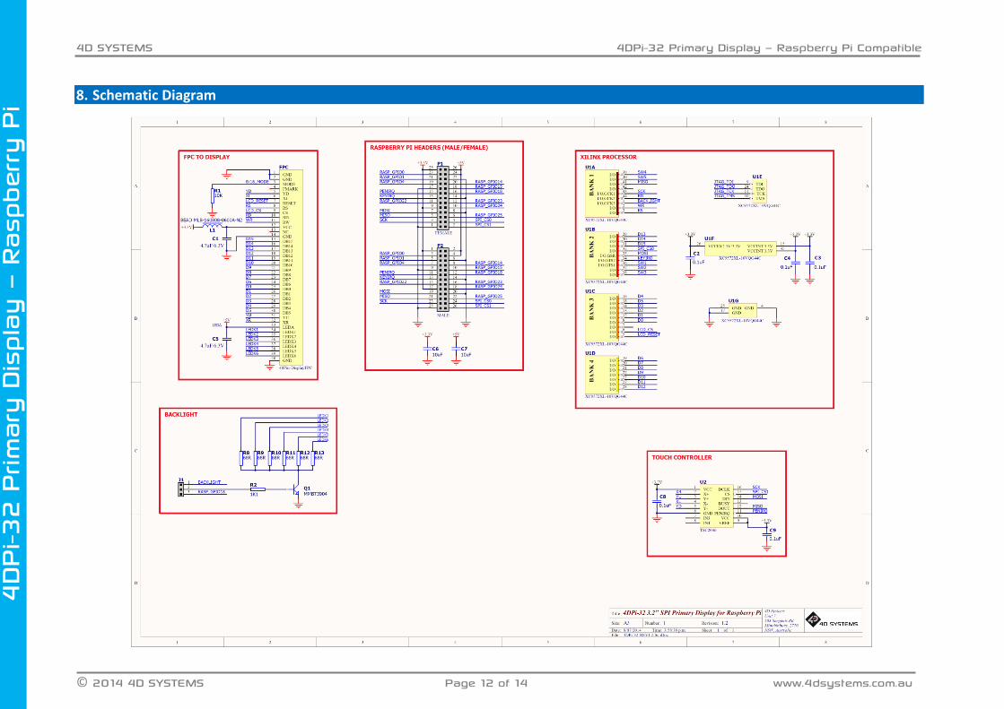
8. Schematic Diagram

4D SYSTEMS 4DPi-32 Primary Display – Raspberry Pi Compatible
© 2014 4D SYSTEMS Page 13 of 14 www.4dsystems.com.au
4DPi-3
2 P
rimary
Dis
pla
y –
Rasp
ber
ry P
i
9. Specifications and Ratings
ABSOLUTE MAXIMUM RATINGS
Operating ambient temperature ................................................................................................... -15°C to +65°C
Storage temperature .......................................................................................................................... -30°C +70°C
NOTE: Stresses above those listed here may cause permanent damage to the device. This is a stress rating only and functional operation of the device at those or any other conditions above those indicated in the recommended operation listings of this specification is not implied. Exposure to maximum rating conditions for extended periods may affect device reliability.
RECOMMENDED OPERATING CONDITIONS
Parameter Conditions Min Typ Max Units
Supply Voltage (+3.3V) Stable external supply required 3.0 3.3 4.0 V
Supply Voltage (+5V) Stable external supply required 4.5 5.0 5.5 V
Operating Temperature -10 -- +60 °C
GLOBAL CHARACTERISTICS BASED ON OPERATING CONDITIONS
Parameter Conditions Min Typ Max Units
Supply Current (ICC) 3.3V Supply -- 100 -- mA
Backlight Current (ICC) 5V Supply -- 150 -- mA
Display Endurance Hours of operation, measured to when display is 50% original brightness
-- 20000 -- H
PERFORMANCE
Parameter Conditions Min Typ Max Units
Frame Rate (FPS)
Video Playback, Full Screen, 320x240. A higher FPS can be achieved if display outputting lots of blocks of the same colour. See Section 4.5
-- 25 -- FPS
ORDERING INFORMATION
Order Code: 4DPi-32
Packaging: Module sealed in an antistatic foam padded 4D Systems box

4D SYSTEMS 4DPi-32 Primary Display – Raspberry Pi Compatible
© 2014 4D SYSTEMS Page 14 of 14 www.4dsystems.com.au
4DPi-3
2 P
rimary
Dis
pla
y –
Rasp
ber
ry P
i
10. Legal Notice Proprietary Information The information contained in this document is the property of 4D Systems Pty. Ltd. and may be the subject of patents pending or granted, and must not be copied or disclosed without prior written permission. 4D Systems endeavours to ensure that the information in this document is correct and fairly stated but does not accept liability for any error or omission. The development of 4D Systems products and services is continuous and published information may not be up to date. It is important to check the current position with 4D Systems. 4D Systems reserves the right to modify, update or makes changes to Specifications or written material without prior notice at any time. All trademarks belong to their respective owners and are recognised and acknowledged. Disclaimer of Warranties & Limitation of Liability 4D Systems makes no warranty, either expressed or implied with respect to any product, and specifically disclaims all other warranties, including, without limitation, warranties for merchantability, non-infringement and fitness for any particular purpose. Information contained in this publication regarding device applications and the like is provided only for your convenience and may be superseded by updates. It is your responsibility to ensure that your application meets with your specifications. Images and graphics used throughout this document are for illustrative purposes only. All images and graphics used are possible to be displayed on the 4D Systems range of products, however the quality may vary. In no event shall 4D Systems be liable to the buyer or to any third party for any indirect, incidental, special, consequential, punitive or exemplary damages (including without limitation lost profits, lost savings, or loss of business opportunity) arising out of or relating to any product or service provided or to be provided by 4D Systems, or the use or inability to use the same, even if 4D Systems has been advised of the possibility of such damages. 4D Systems products are not fault tolerant nor designed, manufactured or intended for use or resale as on line control equipment in hazardous environments requiring fail – safe performance, such as in the operation of nuclear facilities, aircraft navigation or communication systems, air traffic control, direct life support machines or weapons systems in which the failure of the product could lead directly to death, personal injury or severe physical or environmental damage (‘High Risk Activities’). 4D Systems and its suppliers specifically disclaim any expressed or implied warranty of fitness for High Risk Activities. Use of 4D Systems’ products and devices in 'High Risk Activities' and in any other application is entirely at the buyer’s risk, and the buyer agrees to defend, indemnify and hold harmless 4D Systems from any and all damages, claims, suits, or expenses resulting from such use. No licenses are conveyed, implicitly or otherwise, under any 4D Systems intellectual property rights.
11. Contact Information
For Technical Support: [email protected]
For Sales Support: [email protected]
Website: www.4dsystems.com.au
Copyright 4D Systems Pty. Ltd. 2000-2014.