Embed Size (px)
Citation preview

Corresponding Author: Yong Chen 1/24
4D Printing: Design and Fabrication of Smooth Curved Surface Using
Controlled Self-Folding
Dongping Deng, Tsz-Ho Kwok, Yong Chen*
Daniel J. Epstein Department of Industrial and Systems Engineering University of Southern California
Los Angeles, CA, 90089 *Author of correspondence, Phone: (213) 740-7829, Fax: (213) 740-1120, Email: [email protected]
ABSTRACT
Traditional origami structures fold along pre-defined hinges, and the neighboring facets of the hinges are
folded to transform planar surfaces into three-dimensional (3D) shapes. In this study, we present a new
self-folding design and fabrication approach that has no folding hinges and can build 3D structures with
smooth curved surfaces. This four-dimensional (4D) printing method uses a thermal-response control
mechanism, where a thermo shrink film is used as the active material and a photocurable material is used
as the constraint material on the film. When the structure is heated, the two sides of the film will shrink
differently due to the distribution of the constraint material on the film. Consequently, the structure will
deform over time to a 3D surface that has no folding hinges. By properly designing the coated constraint
patterns, the film can be self-folded into different shapes. The relationship between the constraint patterns
and their correspondingly self-folded surfaces has been studied in the paper. Our 4D printing method
presents a simple approach to quickly fabricate a 3D shell structure with smooth curved surfaces by
fabricating a structure with accordingly designed material distribution.
KEYWORDS: Self-folding; 4D printing; curved surface; smooth folding.
1 Introduction
Self-folding structures have received increased attention in recent years, especially with the
demonstration of the four-dimensional (4D) printing concept [1-5]. 4D printing refers to using three-
dimensional (3D) printing technology to fabricate structures with heterogeneous materials; upon
triggering by external stimuli, the structures can evolve over time (the fourth dimension) to form desired
3D shapes. Self-folding structures have great potential in applications such as micro biomedical devices
[6-8], drug delivery systems [9-11], micro reconfigurable robotic systems [12-15], and folded circuit

Corresponding Author: Yong Chen 2/24
designs [16-18]. To achieve automatic folding behaviors, different folding mechanisms have been
developed, including shape memory polymers (SMPs) [19-21], bilayer structures [22-24], and active
hinge-based structures [25-26]. These mechanisms use different materials and designs. Hence the
complexity in fabricating them varies significantly; some of them may take a lot of time and effort in
preparing and assembling the materials, e.g. the structures with embedded shape memory wires.
Pre-strained polystyrene film has been investigated in self-folding applications due to the easiness
of material preparation and low cost. One of the earliest work used black ink and infrared light to achieve
self-folding by localizing the absorption of heat on the hinges [27-29]. The film has also been used as an
active material in a sandwiched structure by coating or gluing another type of material on it. By carefully
designing the parameters on the hinges, well-controlled self-folding could be achieved [30-32]. These
self-folding structures are based on origami design, where the shape is composed of flat facets, and the
structure folding happens at the hinge portions. However, a lot of product designs, as well as the objects
in nature, have shapes with smooth curved surfaces. There is a great need for fabricating curved surfaces,
especially for wearable devices whose shapes are required to conform to the surface of a human body.
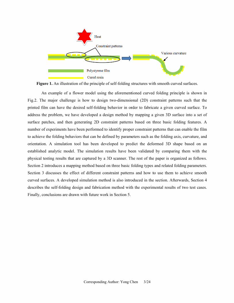
This paper presents a method to self-fold thin shell structures with smooth curved surfaces using
constrained thermal deformation. Since no hinges are used, we name such a self-folding method as
"curved folding". The principle of the method is illustrated in Fig. 1. A bilayer structure design is used in
the thermal-response control mechanism, where a photocurable resin material (thickness ~0.1mm) is
coated on the pre-strained polystyrene film (thickness ~0.3mm) using the mask-image-projection-based
stereolithgraphy (MIP-SL) process, where a mask image is projected onto a thin layer of liquid resin to
selectively solidify it. With no constraints, the polystyrene film shrinks almost uniformly in the XY plane
under homogeneous heating environment. However, when the resin material is coated on one side of the
film, it provides extra physical constraint to the film. Consequently, when the bilayer structure is heated,
the resin material has a small shrinking ratio, while the polystyrene film has a large shrinking ratio.
Different shrinking ratios in the two sides of the film generate a curved deformation; consequently, the
film would be curved up towards the side that has no constraint material. A bi-directional folding can also
be achieved by selectively coating the constraint material on both sides of the film. And, most importantly,
different constraint patterns will lead to varying folding behaviors, and accordingly, resulting in different
3D shapes.
Figu
A
Fig.2. Th
printed fil
address th
surface p
number o
to achieve
orientatio
establishe
physical t
Section 2
Section 3
curved su
describes
Finally, co
ure 1. An illus
An example o
he major chal
lm can have
he problem, w
atches, and t
f experiments
e the folding b
n. A simulat
ed analytic m
testing results
introduces a
discusses th
urfaces. A dev
the self-foldi
onclusions ar
Co
stration of the
of a flower m
llenge is how
the desired s
we have deve
then generati
s have been p
behaviors tha
tion tool has
model. The si
s that are cap
mapping met
he effect of d
veloped simu
ing design an
re drawn with
orresponding A
e principle of
model using th
w to design
self-folding b
eloped a desi
ing 2D const
performed to i
at can be defin
s been devel
imulation res
ptured by a 3D
thod based on
different cons
ulation method
nd fabrication
h future work
Author: Yong C
f self-folding s
he aforement
two-dimensio
behavior in or
gn method b
traint pattern
identify prope
ned by param
loped to pre
sults have be
D scanner. Th
n three basic f
straint pattern
d is also intro
n method with
in Section 5.
Chen 3/24
structures wit
tioned curved
onal (2D) co
rder to fabric
by mapping a
s based on t
er constraint p
meters such as
dict the defo
een validated
he rest of the
folding types
ns and how t
oduced in the
h the experim
th smooth cur
d folding prin
onstraint patte
cate a given c
a given 3D su
three basic fo
patterns that c
the folding a
ormed 3D sh
d by compari
e paper is org
and related f
to use them t
e section. Aft
mental results
rved surfaces
nciple is show
erns such tha
curved surfac
urface into a
folding featur
can enable th
axis, curvature
hape based o
ing them wit
ganized as fol
folding param
to achieve sm
terwards, Sect
s of two test
.
wn in
at the
ce. To
set of
res. A
e film
e, and
on an
th the
llows.
meters.
mooth
tion 4
cases.
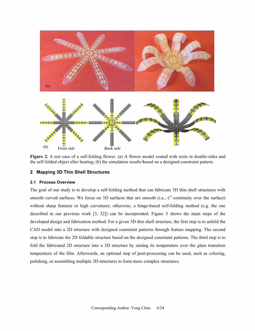
Figure 2.the self-fo
2 Mapp
2.1 Proc
The goal
smooth cu
without s
described
developed
CAD mod
step is to
fold the f
temperatu
polishing,
. A test case olded object a
ping 3D Thin
cess Overvie
of our study
urved surface
harp features
in our prev
d design and f
del into a 2D
fabricate the
fabricated 2D
ure of the film
, or assemblin
Co
of a self-foldafter heating;
n Shell Stru
ew
is to develop
es. We focus
s or high cur
vious work [3
fabrication m
D structure wi
2D foldable s
D structure int
m. Afterward
ng multiple 3D
orresponding A
ding flower. ((b) the simula
uctures
p a self-foldin
on 3D surfac
rvatures; othe
3, 32]) can b
method. For a g
ith designed c
structure base
to a 3D struc
ds, an optiona
D structures t
Author: Yong C
a) A flower mation results b
ng method tha
ces that are s
erwise, a hin
be incorporat
given 3D thin
constraint pat
ed on the desi
cture by raisi
al step of pos
to form more
Chen 4/24
model coatedbased on a de
at can fabrica
smooth (i.e.,
nge-based sel
ted. Figure 3
n shell structu
atterns through
igned constra
ing its tempe
st-processing
complex stru
d with resin inesigned constr
ate 3D thin sh
C1-continuity
f-folding me
3 shows the
ure, the first s
h feature map
aint patterns. T
erature over t
can be used
uctures.
n double-sideraint pattern.
hell structures
y over the su
thod (e.g. th
main steps o
tep is to unfo
pping. The se
The third step
the glass tran
, such as col
es and
s with
urface)
he one
of the
old the
econd
p is to
nsition
oring,

2.2 Fold
A given
parameter
a folding
types incl
method is
parameter
folding ax
flat surfac
In
height of
folding un
of the fol
dual axis
ding Types an
3D curved su
rization and s
unit in our st
luding: (1) fl
s developed f
rs to define th
xis (i.e. the ax
ce patch curve
n our study, fo
the flat surfa
nit is defined
ded surface p
folding, two
Co
F
nd Paramete
urface can b
shape matchin
tudy. When t
lat, i.e., no fo
for a given c
he behavior o
xis along whi
es up). They a
Figure 4.
folding curvat
ace patch curv
as zero. For
patch along t
curvatures (φ
orresponding A
Figure 3. Ma
ers
e divided int
ng [33, 34] (r
the surface pa
olding, (2) on
curved surfac
of a folding un
ich the surfac
are shown in
Folding unit
ture (denoted
ves up) over
the type of o
the direction
φ1 and φ2) can
Author: Yong C
ain steps of th
to a set of s
refer to Fig. 4
atch is small,
ne-axis, and
e based on t
nit are foldin
ce patch folds
Fig.4(c)-4(e)
and the four f
as φ) is defin
the width w
one-axis foldi
that is perpen
n be defined a
Chen 5/24
he process
surface patch
4a); each of th
, it can be cla
(3) dual-axis
this classifica
ng orientation
s), and foldin
, respectively
folding param
ned as the rati
of the foldin
ing, the curva
ndicular to th
along the two
es based on
he surface pat
assified into t
(refer to Fig
ation. In addi
(flat, upward
ng curvature (
y.
meters.
io between th
ng unit. The c
ature is the de
he folding ax
folding direc
the idea of
tches is referr
three basic fo
g. 4b). A ma
ition, three fo
ds, or downw
(i.e. how muc
he depth d (i.e
curvature for
epth-to-width
xis. For the ty
ctions respect
shape
red as
olding
apping
olding
wards),
ch the
e., the
a flat
h ratio
ype of
tively.

Corresponding Author: Yong Chen 6/24
In this study, we assume the dual-axis folding along the two folding axes is symmetrical. Hence the
folding curvature of the surface patch is simplified as the average of φ1 and φ2.
Accordingly, a set of codes can be defined to label each surface patch based on the
aforementioned folding properties. Table 1 shows the codes that are used in the paper to label a surface
patch. A square represents the folding unit, and a solid line in the square represents the folding axis. The
curvature φ is recorded inside the square, and an arrow is used to indicate whether the folding unit folds
upwards or downwards. A horizontal double-sided arrow indicates the flat ones.
Table 1. Illustration of folding codes for labeling folding units.
Flat One axis Dual axis Folding type and
axis Folding curvature 0 φ φ
Folding orientation
or or
Examples
φ
φ
The steps of mapping a 3D structure and generating codes based on the aforementioned
classification are shown in Fig. 5. To map a 3D curved surface, the first step is to divide the given surface
into a mesh grid based on the idea of mesh parameterization. The patch size can be set by users. Generally,
the smaller the size is, the more accurate the mapping would be; however, the required fabrication
resolution of the designed constraint pattern will also be higher. The mesh grid defines a set of small
surface patches that will be deformed into the 3D curved surface. Based on the defined codes, each
surface patch is labeled by its folding type, folding orientation, folding axis, and folding curvature. Fig. 5c
and Fig. 5d show the labels of the mesh grids using the codes in Table 1. The constructed surface patches
and the accordingly defined folding codes on the patches are the key elements of our self-folding structure
design method. We will discuss how to design 2D constraint patterns for each surface patch in Sections 3.

3 Foldi
After a se
patterns fo
folding co
when hea
thermal-re
film serv
constrains
structural
will lead t
of a poly
simulation
3.1 Shri
A polysty
cooling d
energy (in
temperatu
shrink to
shrink un
Figure 5.
ng Control
et of coded s
for them are d
ode of a surfa
ated, will be
esponsive con
es as the ac
s the shrinkag
deformation
to the deform
ystyrene film
n method. Fin
nkage Study
yrene film is
down rapidly
n the form of
ure is raised a
the most stab
iformly on th
Co
An illustratio
Using Cons
surface patch
discussed in th
ace patch to a
self-folded as
ntrol mechani
ctive material
ge of the poly
. As shown in
mation of the 2
m is first pre
nally, the mai
y of Polystyre
produced by
to maintain
f residual stre
above its gla
ble configurat
he film plane
orresponding A
on of mappin
straint Patte
hes have been
his section. T
a constraint p
s designed.
ism using a b
l, and cured
ystyrene film
n our previou
2D structure i
esented, follo
n factors that
ene Film
y stretching a
its stretched
ess) due to th
ss transition
tion. If the pr
under heat. H
Author: Yong C
g a curved su
erns
n generated, t
The main chal
pattern such t
As mentione
ilayer structu
resin is use
. Both the ac
us work [3], h
n certain way
owed by a d
t contribute to
a thick film u
d shape. Con
he use of stre
temperature,
re-stressed po
However, the
Chen 7/24
urface into a s
the design an
llenge to be c
that the accor
ed in Section
ure design. Th
ed as the pa
ctive and pas
heating will
ys. In this sec
discussion on
o the self-fold
under heat int
nsequently, th
etching to ach
the film wil
olystyrene film
e stored poten
set of folding
nd fabrication
considered is h
rdingly fabric
1, our metho
hat is, a pre-st
assive materi
ssive material
cause the film
tion, our stud
n a correspon
ding behaviors
to a certain t
he film stores
hieve its fina
l release the
m is uniforml
ntial energy o
units.
n of the cons
how to conve
cated 2D stru
od is based o
trained polyst
al that selec
ls contribute
m to shrink, w
dy on the shrin
ndingly deve
s are discusse
thickness and
s a large pot
al shape. Whe
stored energ
ly stretched, i
of polystyrene
straint
ert the
ucture,
on the
tyrene
ctively
to the
which
nkage
eloped
ed.
d then
tential
en the
gy and
it will
e film

Corresponding Author: Yong Chen 8/24
may not be uniform due to non-uniform processing conditions. Hence the two sides of the film may
shrink differently.
Figure 6. Shrinking behavior of the polystyrene film.
The polystyrene film used in our study is the inkjet shrink film (clear) purchased from Grafix
(Maple Hts, OH). Tests were first performed to calibrate its shrinkage ratio by measuring the length of
both sides of the film when it is heated to different temperatures. Fig. 6 shows the measured lengths of
both sides of the polystyrene film, which has an original length of 20mm. When the temperature is raised
up above 98oC, the film starts to shrink, and one side of the film (denoted as Side A, red curve) shrinks
slightly more than the other side (denoted as Side B, blue curve). The difference leads to slight bending
of the film at the temperature of 106oC (refer to Fig. 6b). When the temperature keeps increasing, the
shrinkage of Side B catches up with that of Side A; hence the difference becomes smaller. Eventually, the
potential energy is totally released when the temperature reaches around 120oC, and both sides shrink
similarly to get a flat film in a smaller size (~9mm). For the temperature setting between 98oC and 120oC,
each temperature has the corresponding shrinking ratio. The reason is that the polymer chains of the
material is not uniform; hence the phase transition is gradually introduced with the increased temperature
until the film is totally changed at 120oC. If the temperature keeps on increasing to over 120oC, the film

Corresponding Author: Yong Chen 9/24
would become soft or even be melted. Six samples were tested and the same phenomenon is found for all
the tested samples with small variation (<0.2mm or 1% of the original testing length). Hence we used the
graph in Fig. 6(a) as the shrinkage estimation of the polystyrene film in our design.
As mentioned before, 2D patterns are designed to constrain one side of the film to achieve the
bending of the film towards another side. It is desired to have a small shrinkage difference between the
two sides of the film (i.e. Side A and B) such that its effect could be minimized in the pattern design. In
addition, if the shrinkage of the film is too large, the shear stress induced between the film and the coated
material would be large as well. Consequently, the constraint material may be peeled off from the film. In
our study, the shrinkage ratio in all the tests is kept smaller than 25% by using a lower temperature. Based
on the curve shown in Fig. 6(a), the raised temperature in our study is set at 108oC, at which the related
shrinking difference on the two sides of the film is relatively small.
3.2 Deformation Principle and a Simulation Method
Constraint patterns are designed to cause the polystyrene film to shrink differently on both sides. The
shape of the coated constraint material will determine how the fabricated 2D structure will self-fold when
heated. The moment of inertia is one of the main parameters to evaluate how a 2D surface patch will bend.
As shown in Fig. 7, for a surface patch with thickness h , width b and length a , the moment of inertia
I around the X and Y axes is 3
12xbhI = and
3
12yahI = , respectively.
Figure 7. Folding axis analysis.
As the thickness of the constraint layer ( h ) is fixed, the 2D structure tends to bend around the
axis that has a smaller I value. For example, if b << a , the surface patch will bend around the X axis.
In other words, assuming the film portions that are coated with constraint material are protected from
heating and constrained by the coated material, the two sides of the film will shrink differently. Hence the
distribution of the coated material will lead to the bending of the film around the axis that is orthogonal to
the distribution of the constraint material.
A simulation method based on the analyzed deformation principle is developed to predict the
deformed 3D shape for a 2D structure with designed constraint patterns. Similar to the finite element
method (FEM), we subdivide a design domain into a set of small elements, e.g., small cells as shown in

Fig.8(c). W
linearly. I
new lengt
view.
G
Fig.6(a), t
patterns. F
shape with
empty and
can be com
are puttin
approach
set of vert
correspon
squares fi
the eleme
simulation
When the ele
In the simulat
th R L⋅ that i
Figure
Given the shri
the target sha
For example,
h no deforma
d another sid
mputed indiv
ng together, c
a target shap
tices onto the
nding constrai
it of the const
nts (V1,…, Vn
n:
Cor
ements are suf
tion, we assum
is linearly com
8. Deformation
inkage ratio
ape of each e
, when both s
ation througho
de is constrain
vidually for ea
onflicts will
pe with the sm
e target shape
int set. This m
traint shape o
Vn) and Vi ⊆V
rresponding Au
fficiently sma
me the side of
mputed from
n principle use
R, which can
element can b
sides of the e
out the self-fo
ned, it is defo
ach element; h
arise that nee
mallest conflic
e by minimizi
minimum is co
onto the set of
be the vertice
uthor: Yong C
all, the contra
f a shrinking
the original l
ed in simulation
n be obtained
be computed b
element are c
olding proces
ormed like th
however, whe
ed to be resol
ct. Therefore,
ing the sum o
omputed thro
f vertices. Le
es of the i-th e
Chen 10/24
action and de
film without
length L as il
n and the deve
d through the
based on the
constrained, t
ss. However, w
he one shown
en the target s
lved by conn
, the simulati
of the squared
ough shape m
et V be a vect
element. A ne
eformation ca
coated mater
llustrated in F
eloped simulati
e calibration
configuratio
this element
when one sid
n in Fig. 8(a).
shapes of the
necting the el
on is develop
d distances of
matching, i.e. b
tor that stacks
ew function is
an be approxim
rial will shrin
Fig. 8(a) with
ion.
tests as show
on of the cons
will stay the
de of the elem
The target s
neighbor elem
ements togeth
ped by projec
f the vertices
by finding the
s all the vertic
s developed f
mated
nk to a
h a 2D
wn in
straint
same
ment is
shapes
ments
her to
cting a
to the
e least
ces of
for the

Corresponding Author: Yong Chen 11/24
(1)
where with being a matrix with all element equal to 1, and Vi’ is the projected
vertices computed by the target shape. Equation (1) can be rewritten to a linear equation system that can
be solved by a least square solution:
(2)
where A is a 8m×n matrix combines all the mean-centered vertices and p integrates all projections, and
the solution of Equation (2) will be the vertex positions of the simulation mesh such as the ones shown in
Fig.8(c). In other word, it is trying to maintain the rigidity of the transformation between the target and
the current shape of the elements as shown in Fig. 8(b). The computation scheme used in our simulation
method is adopted from the ones that have been used in other engineering applications (e.g. [35, 36]).
Based on the developed simulation tool, an input 2D structure in Fig.8(c) will lead to a 3D shape with the
minimum E as shown in Fig. 8(d). Hence, we can predict the behavior of a designed constraint pattern.
We will discuss the constraint pattern design that can be used to achieve the four folding parameters of a
folding unit in the following two sections.
3.3 Folding Type and Axis Control Using Constraint Patterns
Since the folding type and the axis direction are highly related, we will discuss them together. As shown
in Fig.7, a simple 2D bar ( b << a ) can be used as the constraint pattern if a folding axis is defined. The
direction of the constraint bar (i.e. the direction of the longest edge) should be perpendicular to the
folding axis. Similarly, a 2D cross shape can be used as the constraint pattern for a dual-axis folding.
Fig.9 shows the designed constraint patterns with related experimental results for both one-axis and dual-
axis folding. Five constraint patterns were tested, and the feasibility of using them to achieve the three
basic folding types has been demonstrated. In the designs as shown in Fig.9, the grey portion is the
polystyrene film, and the yellow portion is the designed constraint patterns, which are printed using the
MIP-SL process [32]. The black lines on the film were drawn in order to position the film during the
fabrication process.
As shown in the test results, the folded shapes of both one-axis and dual-axis cases are close to
the desired shapes. Simulation results were also computed for the tests. The steps of the comparison
analysis are shown in Fig. 10. The folded samples are scanned using a SLS-2 3D Scanner (David Vision
Systems GmbH, Germany) with a resolution of 0.06mm. The scan data is then compared with the
simulated data. Since a simulated model is based on a 3D object with certain thickness while the related
3D scanned data is a mesh surface, only the exterior surface of the simulated model is used in the

Corresponding Author: Yong Chen 12/24
comparison analysis. Hausdorff distance is used to evaluate the difference of the two meshes in different
data points. The publicly available software system - Metro [37] is used to compute the Hausdorff
distance between the two meshes. For the test samples with the size of 10mm×10mm, the maximum error
is around 0.8mm. It can be noticed that the majority of the comparison color map is in blue color, while
the boundaries of the patches have large error, which may be due to the different heating conditions along
the boundary.
Figure 9. An illustration of the constraint patterns.

Corresponding Author: Yong Chen 13/24
Figure 10. The comparison analysis of a folded model versus a related simulation model.
Some additional experiments were performed to study the folding performance of the one-axis
folding type. In the tests, the single constraint bar is subdivided into two and three parallel bars by
keeping the total areas of the constraint patterns the same. Fig.11 shows the designed patterns and the
folded results. The blue dashed line in the figure indicates the folding axis. After the folding, we
evaluated the performance of folding by evaluating the straightness of the curve along the folding axis,
which is defined as the axial curve. Theoretically, if the sample is perfectly folded along the axis, the
axial curve is a straight line. However, due to the constraint material, the coated portion will curve up and
form a "bump". When the constraint pattern is divided into smaller parts, smaller "bumps" will form and
the overall smoothness of the structure will be improved. The results show that the more constraint bars
used in a 2D structure, the better overall smoothness the structure can obtain. However, the constraint
pattern cannot be unlimitedly divided into smaller ones since the fabrication process has a limited feature
resolution. In our study, we used three bars as the 2D constraint pattern for the one-axis folding type.
Figure 11. Folding performance of one axis folding using different distributions of materials.

Corresponding Author: Yong Chen 14/24
3.4 Folding Curvature and Orientation Control Using Constraint Patterns
Another important parameter to control the folding of a surface patch is the folding curvature. The factors
that may affect the curvature of a surface patch include the shape of the constraint pattern, the property of
constraint material, the thickness of the constraint layer, and the temperature used in self-folding. In our
study we fix all the factors except the shape of the constraint pattern in order to study the relation between
the folding curvature and the pattern shape. The effects of other factors will be explored in our future
work.
In a folding unit, a constraint pattern for a surface patch can have a wide variety of designs,
including its shape, position, and scale. We limited the pattern designs in our study and chose two
patterns for the one-axis and dual-axis folding, respectively. As shown in Fig.12, a parallel bar pattern is
used for the one-axis folding, and a cross shape pattern is used for the dual-axis folding. Fig.12 also
shows the pattern size and position that are considered in our study. The edge length of a unit surface
patch is denoted as L . The control parameter in these designs is the width of the constraint bar, that is, 1l
in Fig. 12(a) and 2l in Fig. 12(b). We experimentally studied how to set the design parameters to achieve
the desired folding curvatures.
Figure 12. Two constraint pattern examples for two base types.
A set of designed tests were performed to calibrate the relationship between 1l , 2l and their
corresponding curvatures. The fabricated samples and the folded results are shown in Fig.13 and Fig.14.
Similar to Fig. 10, the comparison analysis of the experimented and simulated results were performed. In
addition, the values of the depth and width ( , )d w as discussed in Section 2.2 were measured using a
caliper. Table 2 shows the measurement results. In the tests, the size of each surface patch is
10mm×10mm. Fig.15 shows the plotted curve based on the data in Table 2. The experimental results
illustrate that the constraint patterns for both one-axis and dual-axis folding types can be used to control
the folding curvatures of the polystyrene film. Increasing the parameter 1l and 2l will increase the

Corresponding Author: Yong Chen 15/24
curvatures of the corresponding surface patch. In addition, for a polystyrene film without any constraint
material (i.e. the cases when 1l and 2l equals zero), the curvature is very small compared to the ones with
constraint layers. Hence it can be regarded as the flat folding type.
Figure 13. Curvature control with the parallel bar pattern.
(i) (ii) (iii) (iv) (v) (vi)

Corresponding Author: Yong Chen 16/24
Figure 14. Curvature control with the cross shape pattern.
The relationship between the folding curvature and the parameters of the constraint pattern can be
used in designing the required constraint patterns for a given 3D shell structure. For example, for a folded
3D structure with a specific curvature value, we can determine the parameters 1l (or 2l ) by the curves in
Fig.15. When there is no exact point for a given value, the parameter is approximated by the linear
interpolation between two neighboring data points.
From the measured data, the curvature varies from 0.044 to 0.313. Using our method, it would be
difficult to fabricate sharp features that have large curvatures unless the folding units of the related
features are further subdivided into smaller surface patches. However, using small surface patches will
require a fabrication process that has an even higher resolution. The MIP-SL process used in our study
enables the constraint pattern to have feature size as small as 0.5mm.
Finally, the last folding parameter of a folding unit is the folding orientation. The constraint
material can be coated on either side of the film. When the constraint pattern is coated on one side of the
film, the film will bend towards the other side when heated. Hence, the folding orientation can be easily
controlled by coating the resin on the appropriate side of the film.
(i) (ii) (iii) (iv) (v) (vi)

Corresponding Author: Yong Chen 17/24
Table 2. Results of the folding curvature and bar width from Fig.13 and Fig.14.
One Axis Sample i ii iii iv v vi
1l (bar width)(mm) 0 0.5 1 1.5 2 2.5
depth d (mm) 0.60 1.99 2.07 2.13 2.35 2.60
width w (mm) 9.63 8.81 8.68 8.69 8.84 8.30
curvatureφ 0.062 0.226 0.238 0.245 0.266 0.313
Two Axis Sample i ii iii iv v vi
2l (bar width)(mm)
0 1 2 3 4 5
depth d (mm) 0.61 1.44 1.53 1.76 2.21 2.46
width w (mm) 13.82 13.23 13.31 13.09 13.03 12.84
curvatureφ 0.044 0.109 0.115 0.134 0.170 0.192
Figure 15. Curvature control curves.
4 Constraint Pattern Design and Fabrication
As discussed in Section 3, a 2D film with varying constraint pattern designs can have different folding
performances, which are defined by the four folding parameters on small surface patches. Our 4D printing
approach approximates a smooth surface by a set of surface patches with their curvatures. Accordingly,
the design process to generate the constraint patterns based on the coded surface patches is shown in

Corresponding Author: Yong Chen 18/24
Fig.16. The first step is to calculate the curvatures of each surface patch. A number of points are sampled
along the boundary and the center of each surface patch to measure its width and depth in different
directions. The direction that has the minimum curvature variation along the sampling direction is
selected as the folding axis. If the curvature variation in the orthogonal direction is large (i.e., >0.044 in
the test), the additional direction will be selected as the second folding axis, and the dual-axis pattern will
be used for the surface patch. To achieve the measured curvature of each surface patch, the curves shown
in Fig.15 are used to determine the parameters 1l and 2l . Accordingly, the constraint patterns can be
designed based on the two patterns developed for the one-axis and dual-axis folding types (refer to
Fig.12). Finally, a mask image is generated for coating the constraint material on the polystyrene film,
which will be cut into flat 2D shape.
Figure 16. The constraint pattern design process.

Corresponding Author: Yong Chen 19/24
Fig.17 shows the fabrication system that was used in our study to print the photocurable resin on
the polystyrene film. The fabrication process is based on the MIP-SL process [38-40]. During the
fabrication process, a mask image is projected onto the printing chamber. The polystyrene film is
positioned on the bottom of the chamber, and a layer of liquid resin is spread on top of the polystyrene
film. After that, a transparent cover coated with PDMS film is used to form a thin layer, and the layer
thickness is controlled by spacers. When the resin is exposed to the projected image, the photocurable
resin gets solidified to form the constraint pattern on the polystyrene film. The resin used in our study is
SI500 resin from EnvisionTEC Inc. (Dearborn, MI). The photocuring process will lead to a small
temperature increase [41]; however, it will be far lower than the glass transition temperature of the
polystyrene film.
Figure 17. A fabrication system based on the MIP-SL process.
Fig.18 shows the fabricated film with the designed pattern using the MIP-SL process. After
positioning the fabricated film inside an oven that is pre-heated to 108oC, the structure is self-folded into
the 3D shape as shown in Fig. 18. The self-folded curved surface was captured using the SLS-2 3D
scanner and compared with the designed CAD model. The color map of the Hausdorff Distance shows
that the shapes of the designed and folded models are close to each other. In addition, the folded 3D
structure has the desired curve surface that is smooth. The self-folded curved surface has no folding
hinges, or stair-stepping effect that is typical in the layer-based AM processes. The fabricated 3D
structure can be used as a tool to transfer the shape of the curved surface into other materials such as
silicone rubber. In addition, the folding process takes less than 10 seconds, which is much shorter than the
fabrication time that is required for building the 3D structure using a 3D printer such as a MIP-SL or
fused deposition modeling (FDM) machine.
An additional test case based on “USC” letters is shown in Fig.19. The one-axis folding pattern
design is used in the test. Compared with the layer-based 3D printing of these 3D structures, our method

Corresponding Author: Yong Chen 20/24
does not require the use of additional support structures. The fabrication time is also largely reduced.
Based on the experimental results, the feasibility of using the developed design and fabrication method to
build 3D thin-shell structures with smooth curved surfaces has been demonstrated.
Figure 18. A test case of a bowl.
Figure 19. A test case of “USC” letters.

Corresponding Author: Yong Chen 21/24
5 Conclusion and Discussion
In the paper a new 4D printing approach to fabricate 3D thin shell structures with smooth curved surfaces
has been presented. To control the self-folding process based on a thermal-responsive control mechanism,
a curved surface is divided into a set of small surface patches as individual folding units. Each folding
unit is classified into three basic folding types: the flat patches, the one-axis folding patches, and the dual-
axis folding patches. Three additional parameters are then presented, including folding axis, curvature,
and orientation. The effects of these four parameters and the accordingly developed control methods have
been presented. In addition, a simulation tool has been developed to predict the deformation of a given
constraint pattern. The comparison between the simulated and fabricated shapes shows good agreement.
Several test cases have been presented to demonstrate the effectiveness of the developed 4D printing
method.
There are several limitations in the presented design and fabrication method. Firstly, the degree of
bending is determined by the shrinkage of the polystyrene film. Due to the limit of the shrinkage ratio, our
method cannot be used to fabricate shapes with high curvature. Secondly, the thickness of the constraint
layer needs to be well controlled. A proper thickness of the constraint layer based on the selected
polystyrene film is between 0.1-0.2mm. A concept of digital material by using pixelized constraint
materials on the polystyrene film [38, 39] may enable the method to achieve a larger folding curvature
range and a wider layer thickness. That is, by using different composition of rigid and soft materials, the
printed constraint patterns may have certain flexibility to enable the polystyrene film to have a larger
folding curvature range. Finally, the approach that is used to map the 3D shape into 2D surface is based
on an approximation of the divided surface patches.
Our future work includes: (1) studying more general constraint 2D patterns and their related
control parameters; (2) investigating the use of digital material as the constraint material for self-folding
structures; (3) integrating the developed design method with other 4D printing approaches to fabricate
more complex structures; and (4) investigating applications that may benefit from the developed process.
REFERENCES
[1] Tibbits S, 2014, “4D Printing: Multi-Material Shape Change”, Architectural Design. 84(1):116-21. doi:10.1002/ad.1710
[2] Ge Q, Dunn CK, Qi HJ, Dunn ML, 2014, “Active origami by 4D printing”, Smart Materials and Structures. 23(9):1-15. doi:10.1088/0964-1726/23/9/094007
[3] Kwok TH, Wang CCL, Deng D, Zhang Y, Chen Y, 2015, “4D Printing for Freeform Surfaces: Design Optimization of Origami Structures”, Journal of Mechanical Design. doi:10.1115/1.4031023

Corresponding Author: Yong Chen 22/24
[4] Bakarich SE, Gorkin R, Panhuis Mih, Spinks GM, 2015, “4D Printing with Mechanically Robust, Thermally Actuating Hydrogels”, Macromolecular Rapid Communications; 36(12) :1211-1217. doi:10.1002/marc.201500079
[5] Mao Y, Yu K, Isakov MS, Wu J, Dunn ML, and Qi HJ, 2015, “Sequential Self-Folding Structures by 3D Printed Digital Shape Memory Polymers”, Sci. Rep. 5, 13616; doi: 10.1038/srep13616.
[6] Randall CL, Kalinin YV, Jamal M, Shah A, Gracias DH, 2011, “Self-folding immunoprotective cell encapsulation devices”, Nanomedicine: Nanotechnology, Biology, and Medicine; 7(6): 686-689. doi:10.1016/j.nano.2011.08.020
[7] Malachowski K, Jamal M, Jin Q, Polat B, Morris CJ, Gracias DH, 2014, “Self-Folding Single Cell Grippers”, Nano Letters. 14(7):4164-4170. doi:10.1021/nl500136a
[8] Breger JC, Yoon C, Xiao R, Kwag HR, Wang MO, Fisher JP, et al, 2015, “Self-folding thermo-magnetically responsive soft microgrippers”, ACS applied materials & interfaces. 7(5):3398-3405. doi:10.1021/am508621s
[9] Guan J, He H, Lee LJ, Hansford DJ, 2007, “Fabrication of particulate reservoir-containing, capsulelike, and self-folding polymer microstructures for drug delivery”, Small. 3(3):412-418. doi:10.1002/smll.200600240
[10] Fernandes R, Gracias DH, 2012, “Self-folding polymeric containers for encapsulation and delivery of drugs”, Advanced Drug Delivery Reviews. 64(14):1579-1589. doi:10.1016/j.addr.2012.02.012
[11] He H., Guan J., Lee JL, 2006, “An oral delivery device based on self-folding hydrogels”, Journal of Controlled Release, 110(2), 339-346. doi:10.1016/j.jconrel.2005.10.017
[12] An B, Benbernou N, Demaine ED, Rus D, 2011, “Planning to fold multiple objects from a single self-folding sheet”, Robotica. 29(1):87-102. doi:10.1017/S0263574710000731
[13] Felton S, Tolley M, Demaine E, Rus D, Wood R, 2014, “Applied origami. A method for building self-folding machines”, Science (New York, N.Y.). 345(6197):644.
[14] Sun, X., Felton, S. M., Niiyama, R., Wood, R. J., Kim, S, 2015, “Self-folding and self-actuating robots: A pneumatic approach”, Paper presented at the 2015 IEEE International Conference on Robotics and Automation (ICRA), 3160-3165. doi:10.1109/ICRA.2015.7139634.
[15] Miyashita S, Guitron S, Ludersdorfer M, Sung CR, Rus D, 2015, “An untethered miniature origami robot that self-folds, walks, swims, and degrades”, Paper presented at the 2015 IEEE International Conference on Robotics and Automation (ICRA),1490-1496. doi:10.1109/ICRA.2015.7139386.
[16] Miyashita S, Meeker L, Tolley MT, Wood RJ, Rus D, 2014, “Self-folding miniature elastic electric devices”, Smart Materials and Structures. 23(9):1-9. doi:10.1088/0964-1726/23/9/094005
[17] Miyashita S, Meeker L, Gouldi M, Kawahara Y, Rus D, 2014, “Self-folding printable elastic electric devices: Resistor, capacitor, and inductor”, Paper presented at the 2014 IEEE International Conference on Robotics and Automation (ICRA), 1446-1453. doi:10.1109/ICRA.2014.6907042.
[18] Hayes GJ, Liu Y, Genzer J, Lazzi G, Dickey MD, 2014, “Self-Folding Origami Microstrip Antennas”, IEEE Transactions on Antennas and Propagation. 62(10):5416-5419. doi:10.1109/TAP.2014.2346188

Corresponding Author: Yong Chen 23/24
[19] Peraza-Hernandez E, Hartl D, Galvan E, Malak R, 2013, “Design and Optimization of a Shape Memory Alloy-Based Self-Folding Sheet”, Journal of Mechanical Design. 135(11). doi:10.1115/1.4025382
[20] Peraza-Hernandez EA, Hartl DJ, Malak Jr RJ, 2013, “Design and numerical analysis of an SMA mesh-based self-folding sheet”, Smart Materials and Structures. 22(9):094008,1-17. doi:10.1088/0964-1726/22/9/094008
[21] Felton SM, Becker KP, Aukes DM, Wood RJ, 2015, “Self-folding with shape memory composites at the millimeter scale”, Journal of Micromechanics and Microengineering. 25(8). doi:10.1088/0960-1317/25/8/085004
[22] Ding Z, Wei P., Ziaie B, 2010, “Self-folding smart 3D microstructures using a hydrogel-parylene bilayer”, the 18th Biennial University/Government/Industry Micro/Nano Symposium ,doi:10.1109/UGIM.2010.5508914.
[23] Guan J, He H, Hansford DJ, Lee LJ, 2005, “Self-folding of three-dimensional hydrogel microstructures”, Journal of Physical Chemistry B 109 (49): 23134-7. doi:10.1021/jp054341g
[24] De Leon A, Barnes AC, Thomas P, O'Donnell J, Zorman CA, Advincula RC, 2014, “Transfer printing of self-folding polymer-metal bilayer particles”, ACS Applied Materials & Interfaces 6 (24): 22695-700. doi:10.1021/am5068172
[25] Pickett GT, 2007, “Self-folding origami membranes”, EPL (Europhysics Letters). 78(4):48003. doi:10.1209/0295-5075/78/48003
[26] Guo W, Li M, Zhou J, 2013, “Modeling programmable deformation of self-folding all-polymer structures with temperature-sensitive hydrogels”, Smart Materials and Structures. 22(11):115028,1-6. doi:10.1088/0964-1726/22/11/115028
[27] Liu Y, Boyles JK, Genzer J, Dickey MD, 2012, “Self-folding of polymer sheets using local light absorption”. Soft Matter, 8(6), 1764-1769. doi:10.1039/c1sm06564e
[28] Liu Y, Miskewicz M, Ecsuti MJ, Genzer J, Dickey MD, 2014, “Three-dimensional folding of pre-strained polymer sheets via absorption of laser light”, J. Appl. Phys., 115, 204911. doi:10.1063/1.4880160
[29] Lee Y, Lee H, Hwang T, Lee J, Cho M, 2015, “Sequential Folding using Light-activated Polystyrene Sheet”, Sci. Rep. 5, 16544; doi: 10.1038/srep16544.
[30] Felton SM, Tolley MT, Shin B, Onal CD, Demaine ED, Rus D, Wood RJ, 2013, “Self-folding with shape memory composites”, Soft Matter. 9(32):7688-94. doi:10.1039/c3sm51003d
[31] Tolley MT, Felton SM, Miyashita S, Aukes D, Rus D, Wood RJ, 2014, “Self-folding origami: shape memory composites activated by uniform heating”, Smart Materials and Structures. 23(9):1-9. doi:10.1088/0964-1726/23/9/094006
[32] Deng D, Chen Y, 2015, “Origami-Based Self-Folding Structure Design and Fabrication Using Projection Based Stereolithography”, Journal of Mechanical Design (Transactions of the ASME). 137(2). doi:10.1115/1.4029066

Corresponding Author: Yong Chen 24/24
[33] Yonekura, K., & Watanabe, O. 2014, “A shape parameterization method using principal component analysis in applications to parametric shape optimization”. Journal of Mechanical Design, 136(12), 121401. doi:10.1115/1.4028273
[34] Murray, A., J. Schmiedeler, and B. Korte, 2008, “Kinematic synthesis of planar, shape-changing rigid-body mechanisms”. ASME Journal of Mechanical Design, DOI: 10.1115/1.2829892
[35] Bouaziz S, Deuss M, Schwartzburg Y, Weise T, Pauly M. 2012. “Shape-up: shaping discrete geometry with projections”. Computer Graphics Forum. 31(5): 1657-1667. doi: 10.1111/j.1467-8659.2012.03171
[36] Xie W, Zhang Y, Wang C, Chung R. 2014. “Surface-from-gradients: an approach based on discrete geometry processing,” IEEE Conference on Computer Vision and Pattern Recognition, Columbus, OH, 2014, pp. 2203-2210. doi: 10.1109/CVPR.2014.282
[37] Cignoni P, Rocchini C, Scopigno R. 1998. “Metro: Measuring error on simplified surfaces”. Computer Graphics Forum, 17: 167–174. doi:10.1111/1467-8659.00236
[38] Huang P, Deng D, Chen Y, 2013, “Modeling and fabrication of heterogeneous three-dimensional objects based on additive manufacturing”, 24th International SFF Symposium - An Additive Manufacturing Conference, SFF 2013. 2013:215-230
[39] Zhou C, Chen Y, Yang Z, Khoshnevis B, 2013, “Digital material fabrication using mask-image-projection-based stereolithography”, Rapid Prototyping Journal. 19(3):153-65. doi:10.1108/13552541311312148
[40] Song X, Chen Y, Lee TW, Wu S, Cheng L, 2015, “Ceramic fabrication using Mask-Image-Projection-based Stereolithography integrated with tape-casting”, Journal of Manufacturing Processes. 20:456-64. doi:10.1016/j.jmapro.2015.06.022
[41] Xu K, Chen, Y. 2016, “Photocuring temperature study for curl distortion control in projection based Stereolithography”. Journal of Manufacturing Science and Engineering. 139(2): 021002. doi: 10.1115/1.4034305.