Embed Size (px)
Citation preview
4CH/8CH
Network DVR
User Manual
V2.0.5
1
INDEX
1 STARTING ................................................................................................................................................................ 6
1.1 PRODUCT SPECIFICATION ................................................................................................................................... 6 1.2 WHAT ARE INSIDE THIS DVR PACKAGE? ............................................................................................................... 7 1.3 STARTING THIS DVR ........................................................................................................................................... 8
1.3.1 Before Turning On The DVR........................................................................................................................ 8 1.3.2 DVR local Setup .......................................................................................................................................... 8 1.3.3 DVR Network Setup and Web Browser ....................................................................................................... 8 1.3.4 DVR information after Setup and others ...................................................................................................... 8 1.3.5 CD content inside the package .................................................................................................................... 8
1.4 MENU TREE ..................................................................................................................................................... 10
2 HARDWARE INTRODUCE .................................................................................................................................... 11
2.1 FRONT PANEL ................................................................................................................................................... 11 2.2 REMOTE CONTROLLER ..................................................................................................................................... 13 2.3 REAL PANEL ..................................................................................................................................................... 14 2.4 BASIC INPUT AND VGA/TV OUTPUT SWITCH ...................................................................................................... 15 2.5 HDD INSTALL ................................................................................................................................................... 16 2.6 PTZ CONTROL (RS-485) .................................................................................................................................. 17
3 LOGIN AND POP-UP MENU ................................................................................................................................. 18
3.1 LOGIN DVR ..................................................................................................................................................... 18 3.2 POP-UP MENU .................................................................................................................................................. 18
3.2.1 『Multi-Screen』Display ........................................................................................................................... 19 3.2.2 『Next Screen』Function .......................................................................................................................... 19 3.2.3 『PTZ』Control Function .......................................................................................................................... 20 3.2.4 『Information』Function ............................................................................................................................ 21 3.2.5 『Playback』Function ............................................................................................................................... 24 3.2.6 『Backup』Function .................................................................................................................................. 26 3.2.7 『Logout/Shutdown』Function .................................................................................................................. 26
4 DVR SYSTEM CONFIGURE .................................................................................................................................. 27
4.1 SYSTEM TAB .................................................................................................................................................. 27 4.1.1 『Common Setting』 ................................................................................................................................. 27 4.1.2 『Advance Setting』 ................................................................................................................................. 28 4.1.3 『Maintenance』 ....................................................................................................................................... 30
4.2 CHANNEL TAB ................................................................................................................................................ 31 4.2.1 『Display』Setting ..................................................................................................................................... 31 4.2.2 『Video Setting』 ...................................................................................................................................... 31 4.2.3 『PTZ』Setting .......................................................................................................................................... 34
4.3 LIVE TAB ......................................................................................................................................................... 35 4.3.1 『Video Setting』 ...................................................................................................................................... 35 4.3.2 『Audio Setting』 ...................................................................................................................................... 36
4.4 RECORD TAB ................................................................................................................................................. 37 4.4.1 『Record Schedule』Setting ..................................................................................................................... 37 4.4.2 『Record Quality』Setting ........................................................................................................................ 38
4.5 ALARM TAB .................................................................................................................................................... 40 4.5.1 『Alarm In』Setting ................................................................................................................................... 40
4.6 NETWORK TAB .............................................................................................................................................. 41 4.6.1 『IP Setting』 ............................................................................................................................................ 41 4.6.2 『Port Setting』 ......................................................................................................................................... 42 4.6.3 『Advance Setting』 ................................................................................................................................. 43
5 DVR NETWORK SURVEILLANCE WITH WEB BROWSER ................................................................................ 45
5.1 ENABLE DOWNLOAD UN-SIGNED ACTIVE CONTROL IF NECESSARY ...................................................................... 45 5.2 TURN OFF UAC FOR WINDOWS 7 AND VISTA ...................................................................................................... 45
2
5.3 MICROSOFT INTERNET EXPLORER (IE) .............................................................................................................. 46 5.4 OPERATION – FULL SCREEN/MULTI WINDOW ..................................................................................................... 47 5.5 DVR REMOTE CONFIGURE ............................................................................................................................... 47
5.5.1 『Device parameter』TAB ........................................................................................................................ 48 5.5.2 『Channel setting』TAB ............................................................................................................................ 49 5.5.3 『Record Setting』TAB ............................................................................................................................. 49 5.5.4 『Alarm setting』TAB ................................................................................................................................ 50 5.5.5 『Network management』TAB ................................................................................................................. 51
5.6 IE REMOTE PLAYBACK ...................................................................................................................................... 52 5.6.1 Playback Window ...................................................................................................................................... 52 5.6.2 Playback Operation ................................................................................................................................... 52
5.7 PTZ CONTROL ................................................................................................................................................. 53 5.8 DEVICE INFO. ................................................................................................................................................... 54
5.8.1 『System info.』TAB ................................................................................................................................. 54 5.8.2 『Channel Status』TAB ............................................................................................................................ 54 5.8.3 『Alarm status』TAB ................................................................................................................................. 55 5.8.4 『Network info.』TAB ................................................................................................................................ 55 5.8.5 『Log inquiry』TAB ................................................................................................................................... 56
5.9 BACKUP ........................................................................................................................................................... 56
6 TROUBLESHOOTING ........................................................................................................................................... 58
7 APPENDIX ............................................................................................................................................................. 60
7.1 APPENDIX A-HDD CAPACITY/RECORDING TIME ESTIMATE.................................................................................. 60 7.2 APPENDIX B– COMPATIBLE HDD LIST ............................................................................................................... 60 7.3 APPENDIX C– COMPATIBLE USB PORTABLE DVD BURNER LIST .......................................................................... 61
3
CAUTION TO REDUCE THE RISK OF ELECTRIC SHOCK, DO NOT REMOVE COVER.
NO USER SERVICEABLE PARTS INSIDE.
PLEASE REFER SERVICING TO QUALIFIED SERVICE PERSONNEL.
WARNING TO PREVENT FIRE OR ELECTRIC SHOCK HAZARD, DO NOT EXPOSE THIS
APPLIANCE TO RAIN OR MOISTURE.
NOTE: This equipment has been tested and found to comply with the limits for a
Class “A” digital device, pursuant to Part 15 of the FCC Rules. These limits are
designed to provide reasonable protection against harmful interference when the
equipment is operated in a commercial environment. This equipment generates,
uses and can radiate radio frequency energy and, if not installed and used in
accordance with the instruction manual, may cause harmful interference to radio
communications. Operation of this equipment in a residential area is likely to
cause harmful interference in which case the users will be required to correct the
interference at their own expense.
FCC Caution: To assure continued compliance, use only shielded interface cables
when connecting to computer or peripheral devices. Any changes or
modifications not expressly approved by the party responsible for compliance
could void the user’s authority to operate this equipment.
This Class A digital apparatus meets all the requirements of the Canadian
Interference Causing Equipment Regulations.
4
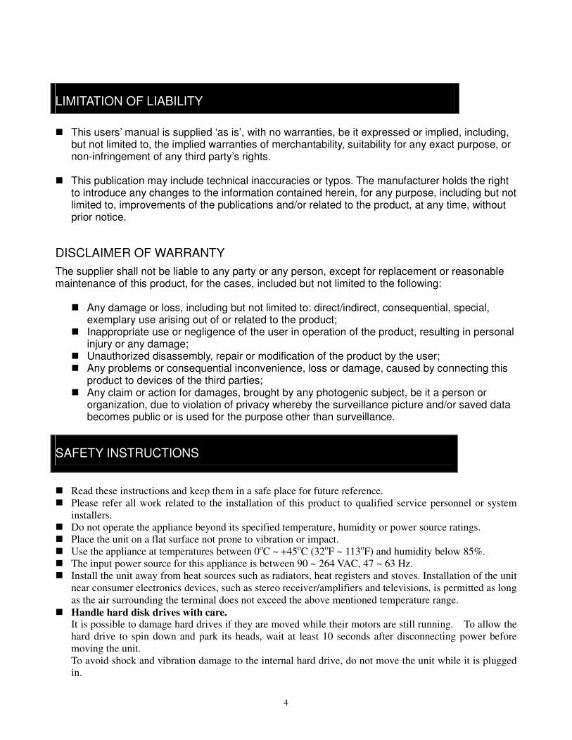
LIMITATION OF LIABILITY
This users’ manual is supplied ‘as is’, with no warranties, be it expressed or implied, including,
but not limited to, the implied warranties of merchantability, suitability for any exact purpose, or non-infringement of any third party’s rights.
This publication may include technical inaccuracies or typos. The manufacturer holds the right
to introduce any changes to the information contained herein, for any purpose, including but not limited to, improvements of the publications and/or related to the product, at any time, without prior notice.
DISCLAIMER OF WARRANTY
The supplier shall not be liable to any party or any person, except for replacement or reasonable maintenance of this product, for the cases, included but not limited to the following:
Any damage or loss, including but not limited to: direct/indirect, consequential, special,
exemplary use arising out of or related to the product; Inappropriate use or negligence of the user in operation of the product, resulting in personal
injury or any damage; Unauthorized disassembly, repair or modification of the product by the user; Any problems or consequential inconvenience, loss or damage, caused by connecting this
product to devices of the third parties; Any claim or action for damages, brought by any photogenic subject, be it a person or
organization, due to violation of privacy whereby the surveillance picture and/or saved data becomes public or is used for the purpose other than surveillance.
SAFETY INSTRUCTIONS
Read these instructions and keep them in a safe place for future reference.
Please refer all work related to the installation of this product to qualified service personnel or system
installers.
Do not operate the appliance beyond its specified temperature, humidity or power source ratings.
Place the unit on a flat surface not prone to vibration or impact.
Use the appliance at temperatures between 0oC ~ +45
oC (32
oF ~ 113
oF) and humidity below 85%.
The input power source for this appliance is between 90 ~ 264 VAC, 47 ~ 63 Hz.
Install the unit away from heat sources such as radiators, heat registers and stoves. Installation of the unit
near consumer electronics devices, such as stereo receiver/amplifiers and televisions, is permitted as long
as the air surrounding the terminal does not exceed the above mentioned temperature range.
Handle hard disk drives with care. It is possible to damage hard drives if they are moved while their motors are still running. To allow the
hard drive to spin down and park its heads, wait at least 10 seconds after disconnecting power before
moving the unit.
To avoid shock and vibration damage to the internal hard drive, do not move the unit while it is plugged
in.
5
Protect hard disk drives from static electricity.
Do not stack hard disk drives or keep them upright.
Do not use an electric or magnetic screwdriver to fix hard disk drives.
Do not place the unit in an enclosed area where the cooling vents are blocked or impede the flow of air
through the ventilation openings.
Protect the power cord from being stepped on or pinched particularly at plugs and the points where they
exit from the apparatus.
Do not drop metallic parts through slots. This could permanently damage the appliance. Turn the
power off immediately and contact qualified service personnel for service.
Handle the appliance with care. Do not drop or shake, as this may damage the device.
Do not expose the appliance to water or moisture, nor try to operate it in wet areas. Do not install the unit
in an area where condensation occurs. Do not operate with wet hands. Take immediate action if the
appliance becomes wet. Turn the power off and refer servicing to qualified service personnel. Moisture
may damage the appliance and also cause electric shock.
Do not use strong or abrasive detergents when cleaning the appliance body. When the dirt is hard to
remove, use a mild detergent and wipe gently.
Do not overload outlets and extension cords as this may result in a risk of fire or electric shock.
Please make a note of your settings and save them. This will help when you are required to change the
system configuration, or when an unexpected failure or trouble occurs.
Distributing, copying, disassembling, reverse compiling, reverse engineering, and also exporting in
violation of export laws of the software provided with this product, is expressly prohibited.
CARING FOR THE ENVIRONMENT BY RECYCLING
When you see this symbol on a product, do not dispose of the product with residential or
commercial waste.
Recycling your Electrical Equipment Please do not dispose of this product with your residential or commercial waste. Some
countries or regions, such as the European Union, have set up systems to collect and recycle
electrical and electronic waste items. Contact your local authorities for information about
practices established for your region
COPYRIGHT STATEMENT All rights reserved. No part of this publication may be reproduced in any form or by any means, transcribed,
translated into any language or computer language, transformed in any other way, stored in a retrieval
system, or transmitted in any form or by any means, electronic, mechanical, recording, photocopying or
otherwise, without the prior written permission of the owner.
6
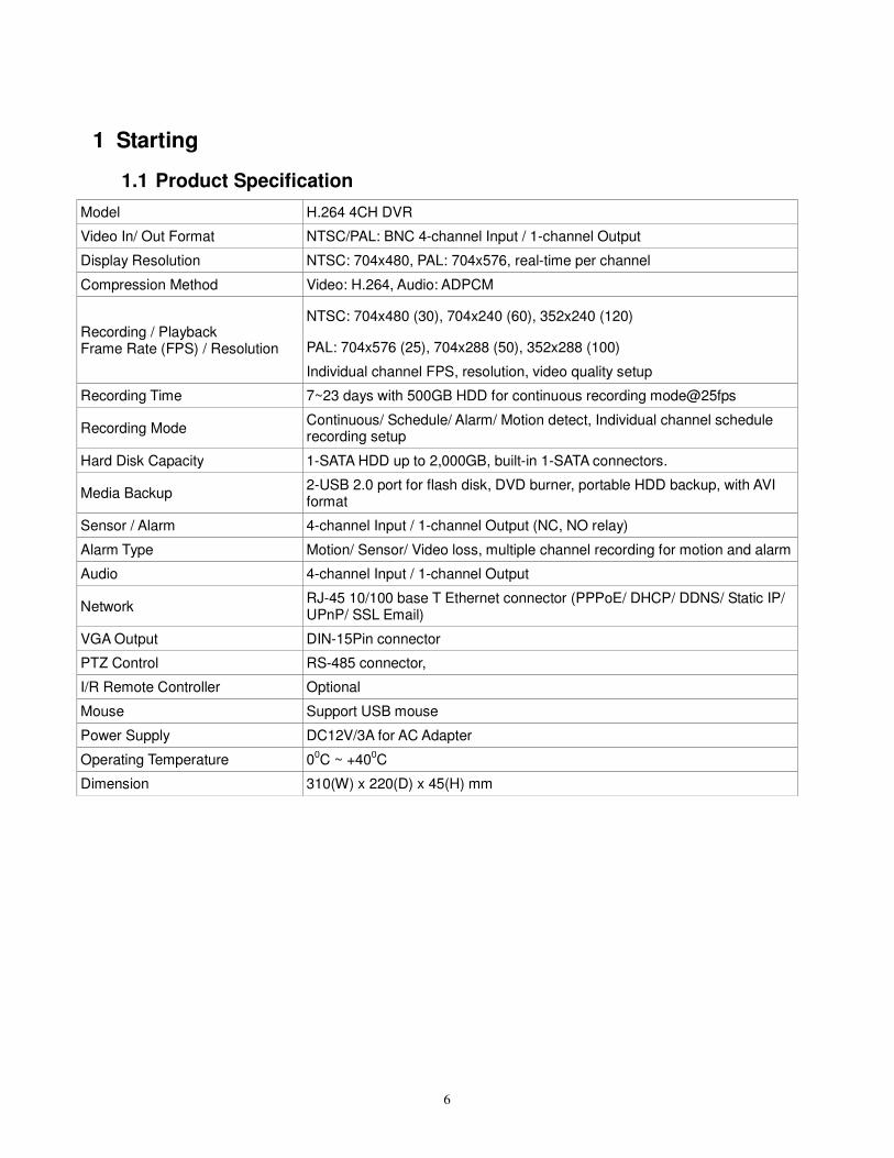
1 Starting
1.1 Product Specification
Model H.264 4CH DVR
Video In/ Out Format NTSC/PAL: BNC 4-channel Input / 1-channel Output
Display Resolution NTSC: 704x480, PAL: 704x576, real-time per channel
Compression Method Video: H.264, Audio: ADPCM
Recording / Playback Frame Rate (FPS) / Resolution
NTSC: 704x480 (30), 704x240 (60), 352x240 (120)
PAL: 704x576 (25), 704x288 (50), 352x288 (100)
Individual channel FPS, resolution, video quality setup
Recording Time 7~23 days with 500GB HDD for continuous recording mode@25fps
Recording Mode Continuous/ Schedule/ Alarm/ Motion detect, Individual channel schedule recording setup
Hard Disk Capacity 1-SATA HDD up to 2,000GB, built-in 1-SATA connectors.
Media Backup 2-USB 2.0 port for flash disk, DVD burner, portable HDD backup, with AVI format
Sensor / Alarm 4-channel Input / 1-channel Output (NC, NO relay)
Alarm Type Motion/ Sensor/ Video loss, multiple channel recording for motion and alarm
Audio 4-channel Input / 1-channel Output
Network RJ-45 10/100 base T Ethernet connector (PPPoE/ DHCP/ DDNS/ Static IP/ UPnP/ SSL Email)
VGA Output DIN-15Pin connector
PTZ Control RS-485 connector,
I/R Remote Controller Optional
Mouse Support USB mouse
Power Supply DC12V/3A for AC Adapter
Operating Temperature 00C ~ +40
0C
Dimension 310(W) x 220(D) x 45(H) mm
7
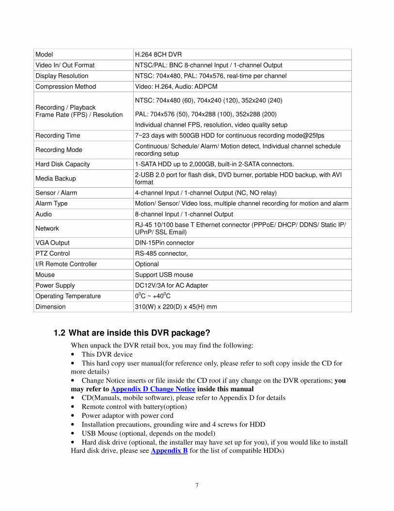
Model H.264 8CH DVR
Video In/ Out Format NTSC/PAL: BNC 8-channel Input / 1-channel Output
Display Resolution NTSC: 704x480, PAL: 704x576, real-time per channel
Compression Method Video: H.264, Audio: ADPCM
Recording / Playback Frame Rate (FPS) / Resolution
NTSC: 704x480 (60), 704x240 (120), 352x240 (240)
PAL: 704x576 (50), 704x288 (100), 352x288 (200)
Individual channel FPS, resolution, video quality setup
Recording Time 7~23 days with 500GB HDD for continuous recording mode@25fps
Recording Mode Continuous/ Schedule/ Alarm/ Motion detect, Individual channel schedule recording setup
Hard Disk Capacity 1-SATA HDD up to 2,000GB, built-in 2-SATA connectors.
Media Backup 2-USB 2.0 port for flash disk, DVD burner, portable HDD backup, with AVI format
Sensor / Alarm 4-channel Input / 1-channel Output (NC, NO relay)
Alarm Type Motion/ Sensor/ Video loss, multiple channel recording for motion and alarm
Audio 8-channel Input / 1-channel Output
Network RJ-45 10/100 base T Ethernet connector (PPPoE/ DHCP/ DDNS/ Static IP/ UPnP/ SSL Email)
VGA Output DIN-15Pin connector
PTZ Control RS-485 connector,
I/R Remote Controller Optional
Mouse Support USB mouse
Power Supply DC12V/3A for AC Adapter
Operating Temperature 00C ~ +400C
Dimension 310(W) x 220(D) x 45(H) mm
1.2 What are inside this DVR package?
When unpack the DVR retail box, you may find the following:
• This DVR device
• This hard copy user manual(for reference only, please refer to soft copy inside the CD for
more details)
• Change Notice inserts or file inside the CD root if any change on the DVR operations; you
may refer to Appendix D Change Notice inside this manual
• CD(Manuals, mobile software), please refer to Appendix D for details
• Remote control with battery(option)
• Power adaptor with power cord
• Installation precautions, grounding wire and 4 screws for HDD
• USB Mouse (optional, depends on the model)
• Hard disk drive (optional, the installer may have set up for you), if you would like to install
Hard disk drive, please see Appendix B for the list of compatible HDDs)
8
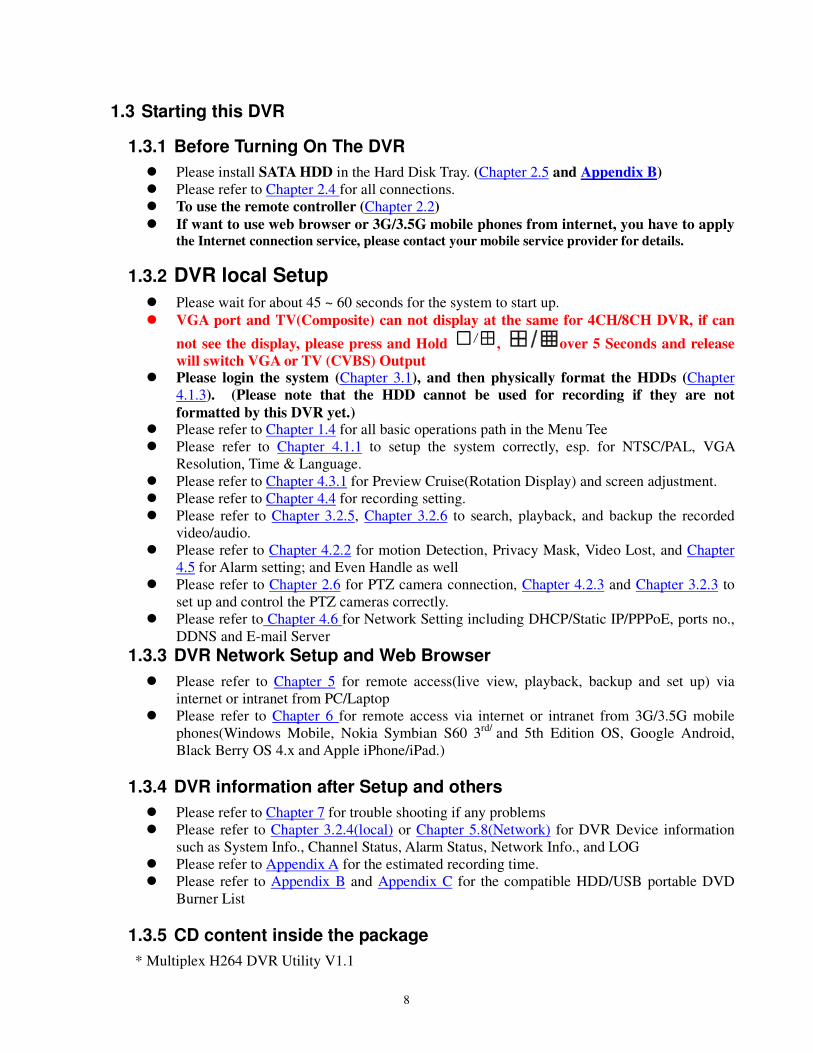
1.3 Starting this DVR
1.3.1 Before Turning On The DVR
Please install SATA HDD in the Hard Disk Tray. (Chapter 2.5 and Appendix B)
Please refer to Chapter 2.4 for all connections.
To use the remote controller (Chapter 2.2)
If want to use web browser or 3G/3.5G mobile phones from internet, you have to apply the Internet connection service, please contact your mobile service provider for details.
1.3.2 DVR local Setup
Please wait for about 45 ~ 60 seconds for the system to start up.
VGA port and TV(Composite) can not display at the same for 4CH/8CH DVR, if can
not see the display, please press and Hold , over 5 Seconds and release
will switch VGA or TV (CVBS) Output Please login the system (Chapter 3.1), and then physically format the HDDs (Chapter
4.1.3). (Please note that the HDD cannot be used for recording if they are not
formatted by this DVR yet.) Please refer to Chapter 1.4 for all basic operations path in the Menu Tee
Please refer to Chapter 4.1.1 to setup the system correctly, esp. for NTSC/PAL, VGA
Resolution, Time & Language.
Please refer to Chapter 4.3.1 for Preview Cruise(Rotation Display) and screen adjustment.
Please refer to Chapter 4.4 for recording setting.
Please refer to Chapter 3.2.5, Chapter 3.2.6 to search, playback, and backup the recorded
video/audio.
Please refer to Chapter 4.2.2 for motion Detection, Privacy Mask, Video Lost, and Chapter
4.5 for Alarm setting; and Even Handle as well
Please refer to Chapter 2.6 for PTZ camera connection, Chapter 4.2.3 and Chapter 3.2.3 to
set up and control the PTZ cameras correctly.
Please refer to Chapter 4.6 for Network Setting including DHCP/Static IP/PPPoE, ports no.,
DDNS and E-mail Server
1.3.3 DVR Network Setup and Web Browser
Please refer to Chapter 5 for remote access(live view, playback, backup and set up) via
internet or intranet from PC/Laptop
Please refer to Chapter 6 for remote access via internet or intranet from 3G/3.5G mobile
phones(Windows Mobile, Nokia Symbian S60 3rd/
and 5th Edition OS, Google Android,
Black Berry OS 4.x and Apple iPhone/iPad.)
1.3.4 DVR information after Setup and others
Please refer to Chapter 7 for trouble shooting if any problems
Please refer to Chapter 3.2.4(local) or Chapter 5.8(Network) for DVR Device information
such as System Info., Channel Status, Alarm Status, Network Info., and LOG
Please refer to Appendix A for the estimated recording time.
Please refer to Appendix B and Appendix C for the compatible HDD/USB portable DVD
Burner List
1.3.5 CD content inside the package
* Multiplex H264 DVR Utility V1.1
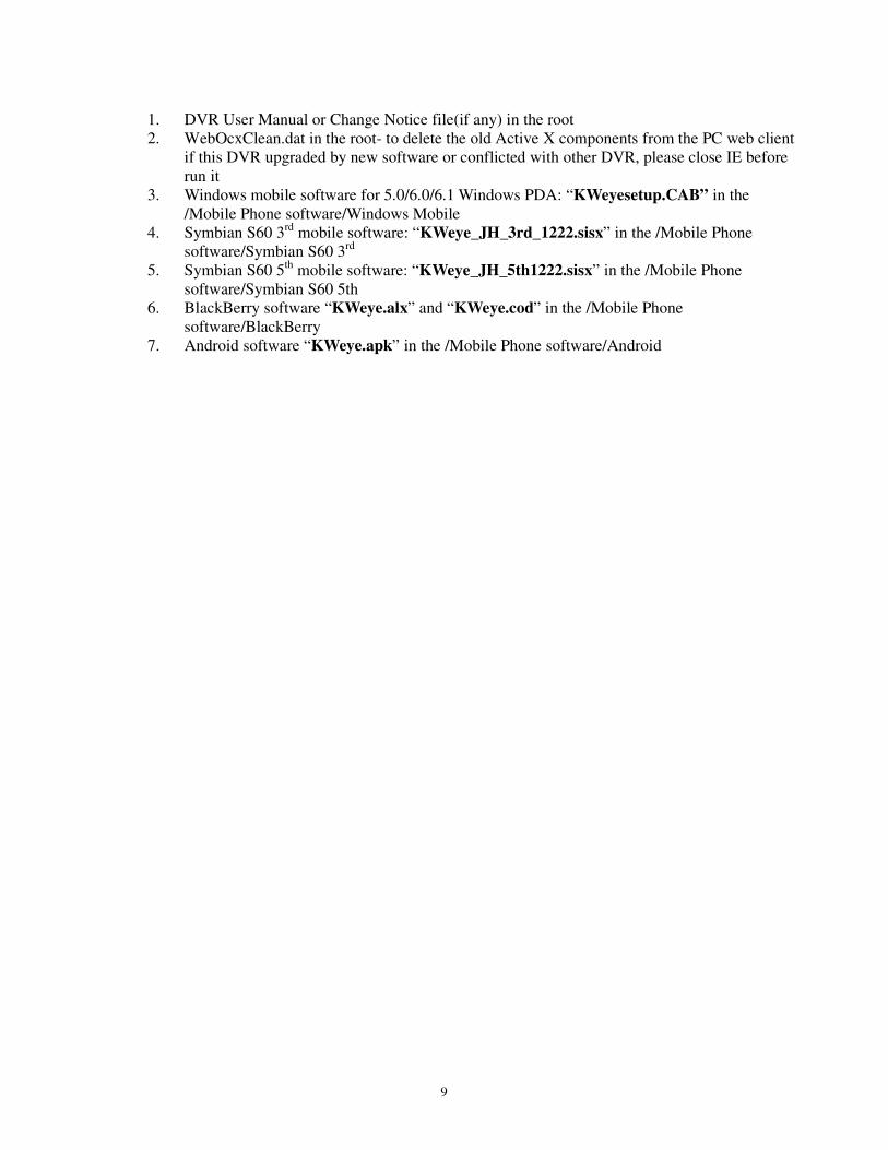
9
1. DVR User Manual or Change Notice file(if any) in the root
2. WebOcxClean.dat in the root- to delete the old Active X components from the PC web client
if this DVR upgraded by new software or conflicted with other DVR, please close IE before
run it
3. Windows mobile software for 5.0/6.0/6.1 Windows PDA: “KWeyesetup.CAB” in the
/Mobile Phone software/Windows Mobile
4. Symbian S60 3rd
mobile software: “KWeye_JH_3rd_1222.sisx” in the /Mobile Phone
software/Symbian S60 3rd
5. Symbian S60 5th
mobile software: “KWeye_JH_5th1222.sisx” in the /Mobile Phone
software/Symbian S60 5th
6. BlackBerry software “KWeye.alx” and “KWeye.cod” in the /Mobile Phone
software/BlackBerry
7. Android software “KWeye.apk” in the /Mobile Phone software/Android
10
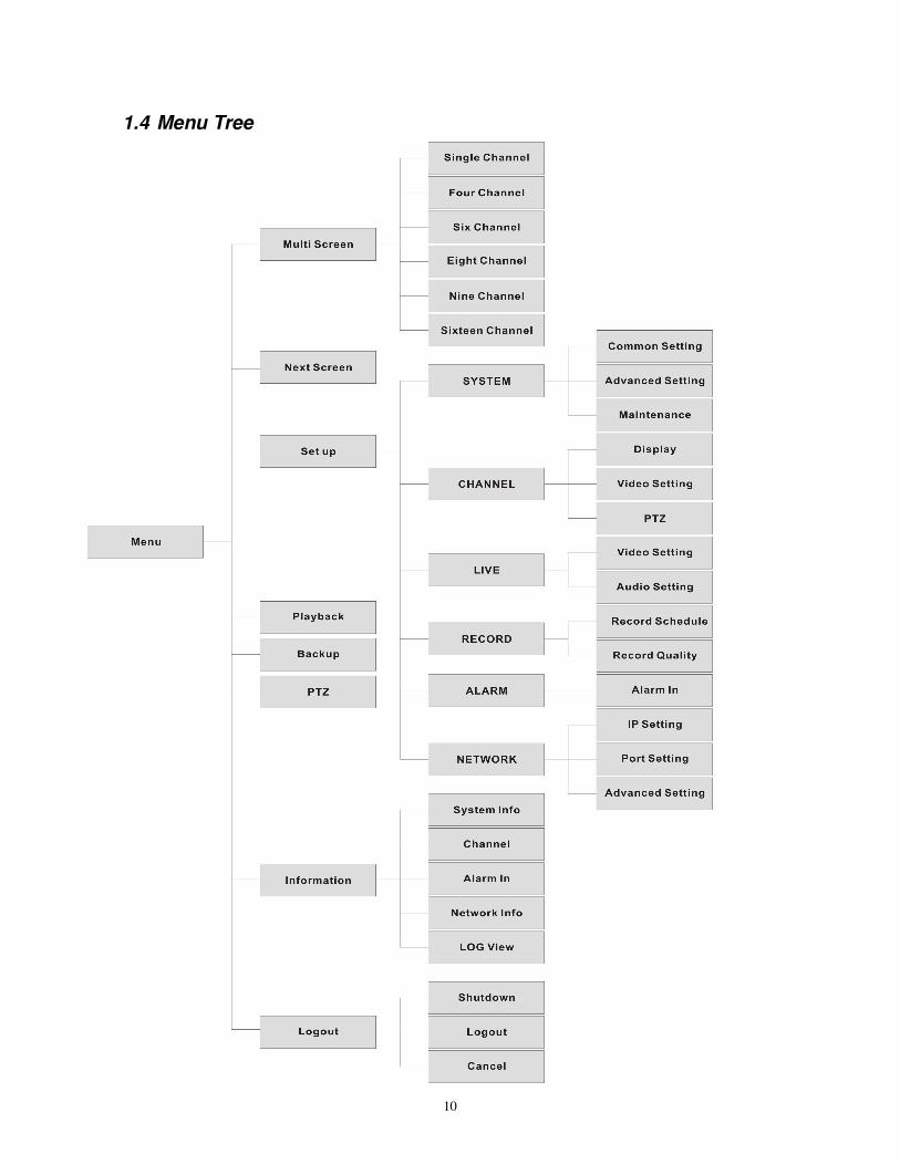
1.4 Menu Tree
11
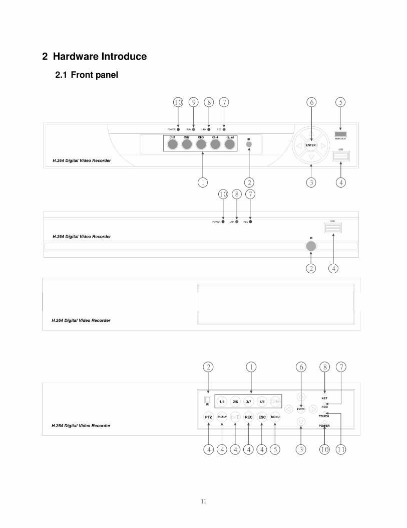
2 Hardware Introduce
2.1 Front panel
12
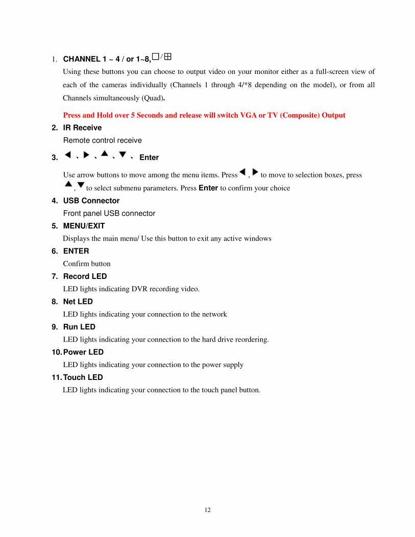
1. CHANNEL 1 ~ 4 / or 1~8,
Using these buttons you can choose to output video on your monitor either as a full-screen view of
each of the cameras individually (Channels 1 through 4/*8 depending on the model), or from all
Channels simultaneously (Quad).
Press and Hold over 5 Seconds and release will switch VGA or TV (Composite) Output
2. IR Receive
Remote control receive
3. 、、、、 、、、、 、、、、 、、、、 Enter
Use arrow buttons to move among the menu items. Press , to move to selection boxes, press
, to select submenu parameters. Press Enter to confirm your choice
4. USB Connector
Front panel USB connector
5. MENU/EXIT
Displays the main menu/ Use this button to exit any active windows
6. ENTER
Confirm button
7. Record LED
LED lights indicating DVR recording video.
8. Net LED
LED lights indicating your connection to the network
9. Run LED
LED lights indicating your connection to the hard drive reordering.
10. Power LED
LED lights indicating your connection to the power supply
11. Touch LED
LED lights indicating your connection to the touch panel button.
13
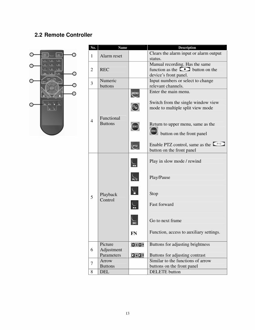
2.2 Remote Controller
No. Name Description
1 Alarm reset Clears the alarm input or alarm output
status.
2 REC
Manual recording. Has the same
function as the button on the
device’s front panel.
3 Numeric
buttons
Input numbers or select to change
relevant channels.
4 Functional
Buttons
Enter the main menu.
Switch from the single window view
mode to multiple split view mode
Return to upper menu, same as the
button on the front panel
Enable PTZ control, same as the
button on the front panel
5 Playback
Control
FN
Play in slow mode / rewind
Play/Pause
Stop
Fast forward
Go to next frame
Function, access to auxiliary settings.
6
Picture
Adjustment
Parameters
Buttons for adjusting brightness
Buttons for adjusting contrast
7 Arrow
Buttons
Similar to the functions of arrow
buttons on the front panel
8 DEL DELETE button
14
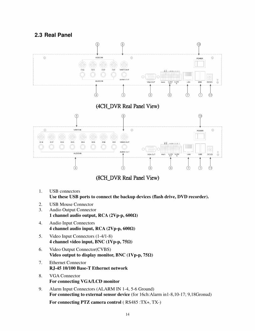
2.3 Real Panel
(4CH_DVR Real Panel View)(4CH_DVR Real Panel View)(4CH_DVR Real Panel View)(4CH_DVR Real Panel View)
((((8CH8CH8CH8CH_DVR Real Panel View)_DVR Real Panel View)_DVR Real Panel View)_DVR Real Panel View)
1. USB connectors
Use these USB ports to connect the backup devices (flash drive, DVD recorder).
2. USB Mouse Connector
3. Audio Output Connector
1 channel audio output, RCA (2Vp-p, 600Ω)
4. Audio Input Connectors
4 channel audio input, RCA (2Vp-p, 600Ω)
5. Video Input Connectors (1-4/1-8)
4 channel video input, BNC (1Vp-p, 75Ω)
6. Video Output Connector(CVBS)
Video output to display monitor, BNC (1Vp-p, 75Ω)
7. Ethernet Connector
RJ-45 10/100 Base-T Ethernet network
8. VGA Connector
For connecting VGA/LCD monitor
9. Alarm Input Connectors (ALARM IN 1-4, 5-6 Ground)
For connecting to external sensor device (for 16ch:Alarm in1-8,10-17; 9,18Gronud)
For connecting PTZ camera control ( RS485 :TX+, TX-)
15
10. Power Switch
11. Power Input Socket (12V DC)
TV(Composite) and VGA output can not be at the same time for 4CH, please press, “Quad” for
more than 5 seconds and release to switch
2.4 Basic Input and VGA/TV Output Switch
Cameras Connect each of the cameras’ outputs to the video input socket in the rear panel of the DVR using appropriate cables. The video input interface is a standard BNC connector, 1Vp-p, 75 Ω. Please keep the video signal cable away from strong electromagnetic and electric interference.
Audio Connection The audio input interface is a standard RCA socket, 2Vp-p, 600 Ω. Please keep the audio signal cable away from strong electromagnetic and electric interference. Remark: for audio input, please consider “ACTIVE MICROPHONE” to increase input voice level for better audio record quality.
Monitor Connect the main output connector to a monitor or a TV screen. Use the BNC-to-RCA connector to work with the Audio/Video RCA cable.
Power Please use the 12V DC adapter supplied for connecting your DVR device with the power source.
Alarm Input/output Connect Alarm In 1-4 to N.O. (Normally Open) or N.C. (Normally Closed) alarm connectors and one Ground connection. Connect Alarm Out to the corresponding connections and Ground accordingly.
Ethernet
For remote access to the video images from your cameras via LAN or the Internet, please connect the standard RJ-45 twisted-pair Ethernet cable to the Ethernet connector.
USB
For connecting the mouse, USB flash drive, USB portable HDD, USB portable DVD Recorder (for the list of compatible HDDs see Appendix 3, for the list of compatible DVD Recorders see Appendix 4).
16
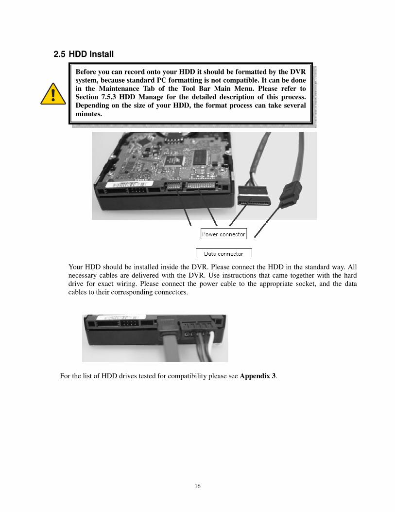
2.5 HDD Install
Your HDD should be installed inside the DVR. Please connect the HDD in the standard way. All
necessary cables are delivered with the DVR. Use instructions that came together with the hard
drive for exact wiring. Please connect the power cable to the appropriate socket, and the data
cables to their corresponding connectors.
For the list of HDD drives tested for compatibility please see Appendix 3.
Before you can record onto your HDD it should be formatted by the DVR
system, because standard PC formatting is not compatible. It can be done
in the Maintenance Tab of the Tool Bar Main Menu. Please refer to
Section 7.5.3 HDD Manage for the detailed description of this process.
Depending on the size of your HDD, the format process can take several
minutes.
17
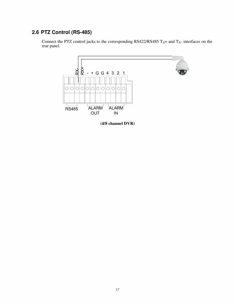
2.6 PTZ Control (RS-485)
Connect the PTZ control jacks to the corresponding RS422/RS485 TX+ and TX- interfaces on the rear panel.
(4/8 channel DVR)
18
3 Login and Pop-up Menu
3.1 Login DVR
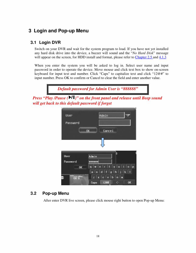
Switch on your DVR and wait for the system program to load. If you have not yet installed
any hard disk drive into the device, a buzzer will sound and the “No Hard Disk” message
will appear on the screen, for HDD install and format, please refer to Chapter 2.5 and 4.1.3
When you enter the system you will be asked to log in. Select user name and input
password in order to operate the device. Move mouse and click text box to show on-screen
keyboard for input text and number. Click “Caps” to capitalize text and click “12@#” to
input number. Press OK to confirm or Cancel to clear the field and enter another value.
Default password for Admin User is “888888”
Press “Play /Pause ( )” on the front panel and release until Beep sound
will get back to this default password if forget
3.2 Pop-up Menu
After enter DVR live screen, please click mouse right button to open Pop-up Menu:
19
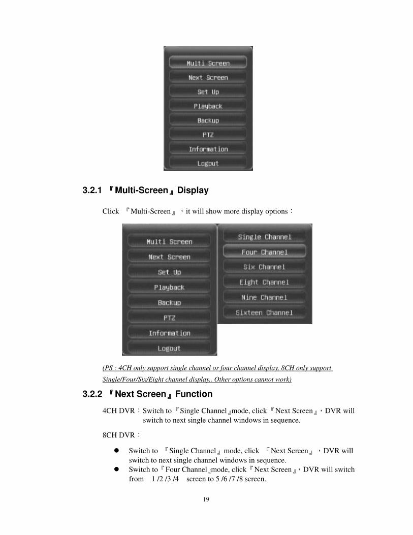
3.2.1 『『『『Multi-Screen』』』』Display
Click 『Multi-Screen』,it will show more display options:
(PS : 4CH only support single channel or four channel display, 8CH only support
Single/Four/Six/Eight channel display.. Other options cannot work)
3.2.2 『『『『Next Screen』』』』Function
4CH DVR:Switch to 『Single Channel』mode, click 『Next Screen』,DVR will
switch to next single channel windows in sequence.
8CH DVR:
Switch to 『Single Channel』mode, click 『Next Screen』,DVR will
switch to next single channel windows in sequence.
Switch to 『Four Channel』mode, click 『Next Screen』,DVR will switch
from 1 /2 /3 /4 screen to 5 /6 /7 /8 screen.
20
Switch to 『Six Channel』mode, click 『Next Screen』,DVR will switch
from 1 /2 /3 /4 /5 /6 screen to 3/ 4/ 5 /6 /7 /8 screen.
16CH DVR:
Switch to 『Single Channel』mode, click 『Next Screen』,DVR will
switch to next single channel windows in sequence.
Switch to 『Four Channel』mode, click 『Next Screen』,DVR will switch
from 1 /2 /3 /4 screen to 5 /6 /7 /8 screen.
Switch to 『Six Channel』mode, click 『Next Screen』,DVR will switch
from 1 /2 /3 /4 /5 /6 screen to 3/ 4/ 5 /6 /7 /8 screen.
Switch to 『Eight Channel』mode, click 『Next Screen』,DVR will
switch from 1 /2 /3 /4 /5 /6 /7 /8 screen to 9/ 10/ 11/ 12/ 13/ 14/ 15/ 16
Switch to 『Nine Channel』mode, click 『Next Screen』,DVR will
switch from 1 /2 /3 /4 /5 /6 /7 /8 /9 screen to 8/ 9/ 10/ 11/ 12/ 13/ 14/ 15/
16
Switch to 『Sixteen Channel』mode, click 『Next Screen』,DVR will
switch from 1 /2 /3 /4 /5 /6 /7 /8 /9 /10/ 11/ 12/ 13/ 14/ 15/ 16 screen
3.2.3 『『『『PTZ』』』』Control Function
There are two modes for 『PTZ』camera control:
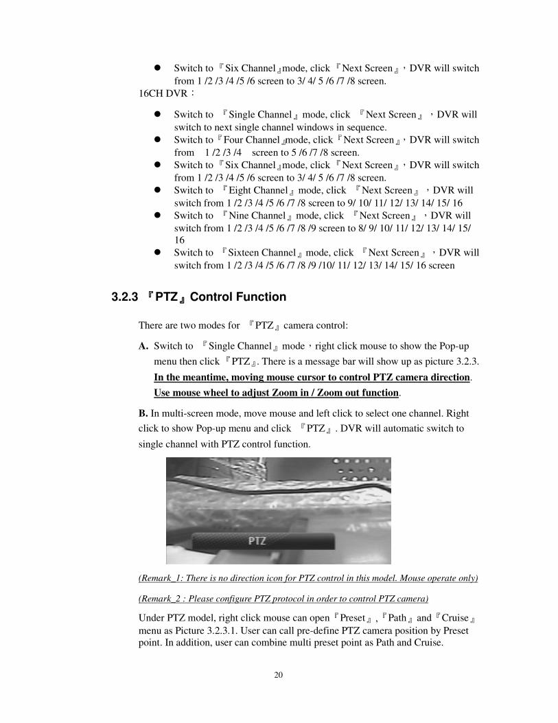
A. Switch to 『Single Channel』mode,right click mouse to show the Pop-up
menu then click 『PTZ』. There is a message bar will show up as picture 3.2.3.
In the meantime, moving mouse cursor to control PTZ camera direction.
Use mouse wheel to adjust Zoom in / Zoom out function.
B. In multi-screen mode, move mouse and left click to select one channel. Right
click to show Pop-up menu and click 『PTZ』. DVR will automatic switch to
single channel with PTZ control function.
(Remark_1: There is no direction icon for PTZ control in this model. Mouse operate only)
(Remark_2 : Please configure PTZ protocol in order to control PTZ camera)
Under PTZ model, right click mouse can open『Preset』,『Path』and『Cruise』
menu as Picture 3.2.3.1. User can call pre-define PTZ camera position by Preset
point. In addition, user can combine multi preset point as Path and Cruise.
21
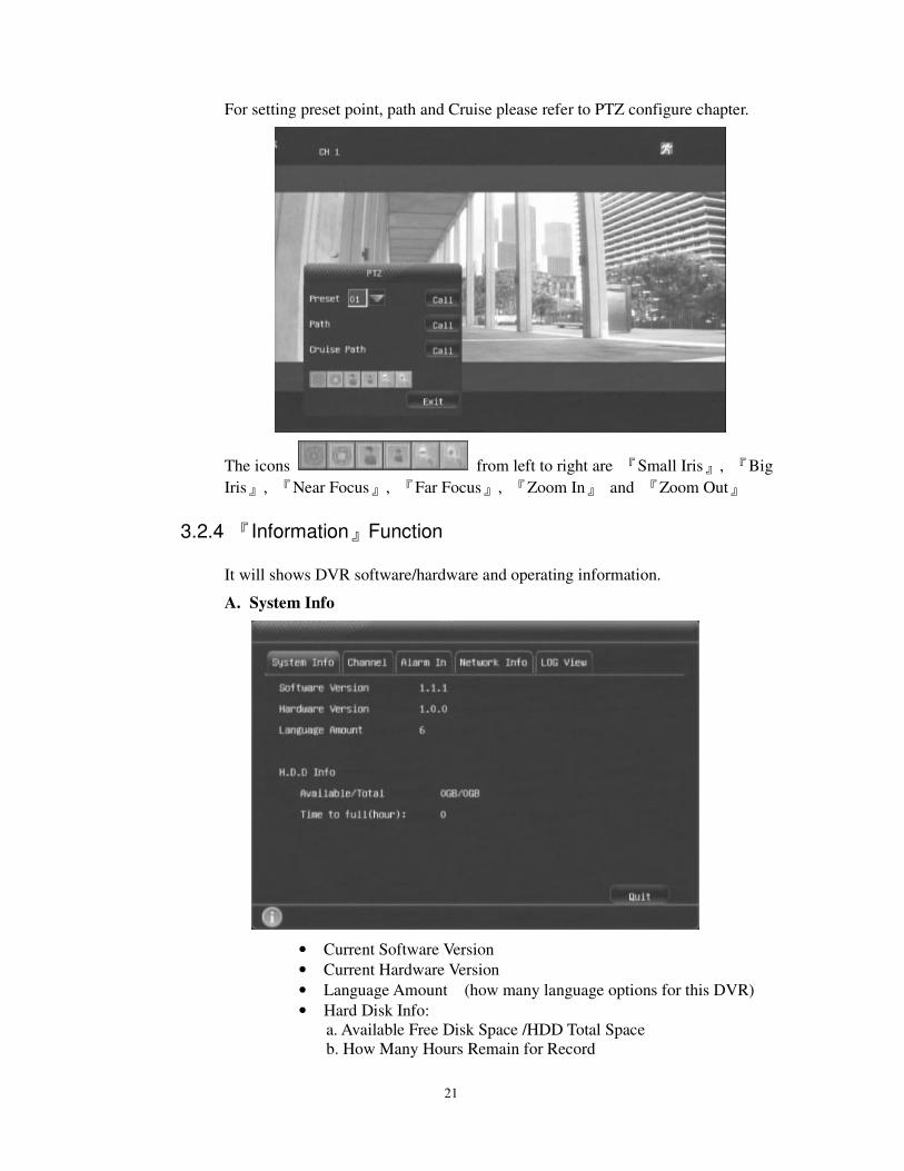
For setting preset point, path and Cruise please refer to PTZ configure chapter.
The icons from left to right are 『Small Iris』, 『Big
Iris』, 『Near Focus』, 『Far Focus』, 『Zoom In』 and 『Zoom Out』
3.2.4 『Information』Function
It will shows DVR software/hardware and operating information.
A. System Info
• Current Software Version
• Current Hardware Version
• Language Amount (how many language options for this DVR)
• Hard Disk Info:
a. Available Free Disk Space /HDD Total Space
b. How Many Hours Remain for Record
22
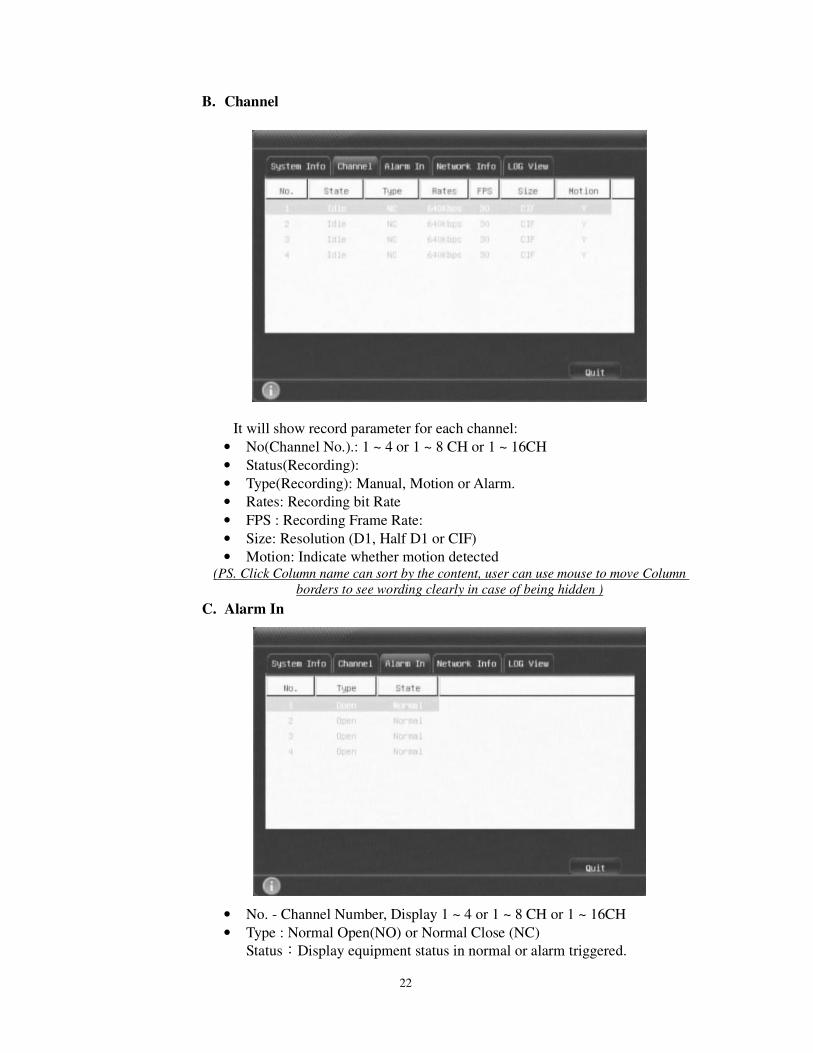
B. Channel
It will show record parameter for each channel:
• No(Channel No.).: 1 ~ 4 or 1 ~ 8 CH or 1 ~ 16CH
• Status(Recording):
• Type(Recording): Manual, Motion or Alarm.
• Rates: Recording bit Rate
• FPS : Recording Frame Rate:
• Size: Resolution (D1, Half D1 or CIF)
• Motion: Indicate whether motion detected (PS. Click Column name can sort by the content, user can use mouse to move Column
borders to see wording clearly in case of being hidden )
C. Alarm In
• No. - Channel Number, Display 1 ~ 4 or 1 ~ 8 CH or 1 ~ 16CH
• Type : Normal Open(NO) or Normal Close (NC)
Status:Display equipment status in normal or alarm triggered.
23
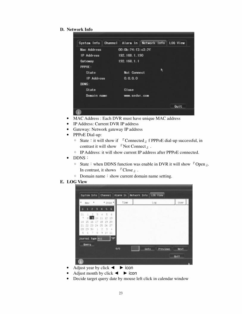
D. Network Info
• MAC Address : Each DVR must have unique MAC address
• IP Address: Current DVR IP address
• Gateway: Network gateway IP address
• PPPoE Dial-up:
State:it will show if 『Connected』f PPPoE dial-up successful, in
contrast it will show 『Not Connect』.
IP Address: it will show current IP address after PPPoE connected.
• DDNS:
State:when DDNS function was enable in DVR it will show 『Open』.
In contrast, it shows 『Close』.
Domain name:show current domain name setting.
E. LOG View
• Adjust year by click icon
• Adjust month by click icon
• Decide target query date by mouse left click in calendar window
24
• Choose 『Journal Type』from following options『All, Operation, Abnormal
and Event』
• Click 『Query』, DVR start search data and list in right window
Click column header can sort journal list
After Query, it will show the page list, you can click 『Previous』/『Next』
or input page no., and click『Goto』to find the page
(User can use mouse to move Column borders to see wording clearly in case of being hidden )
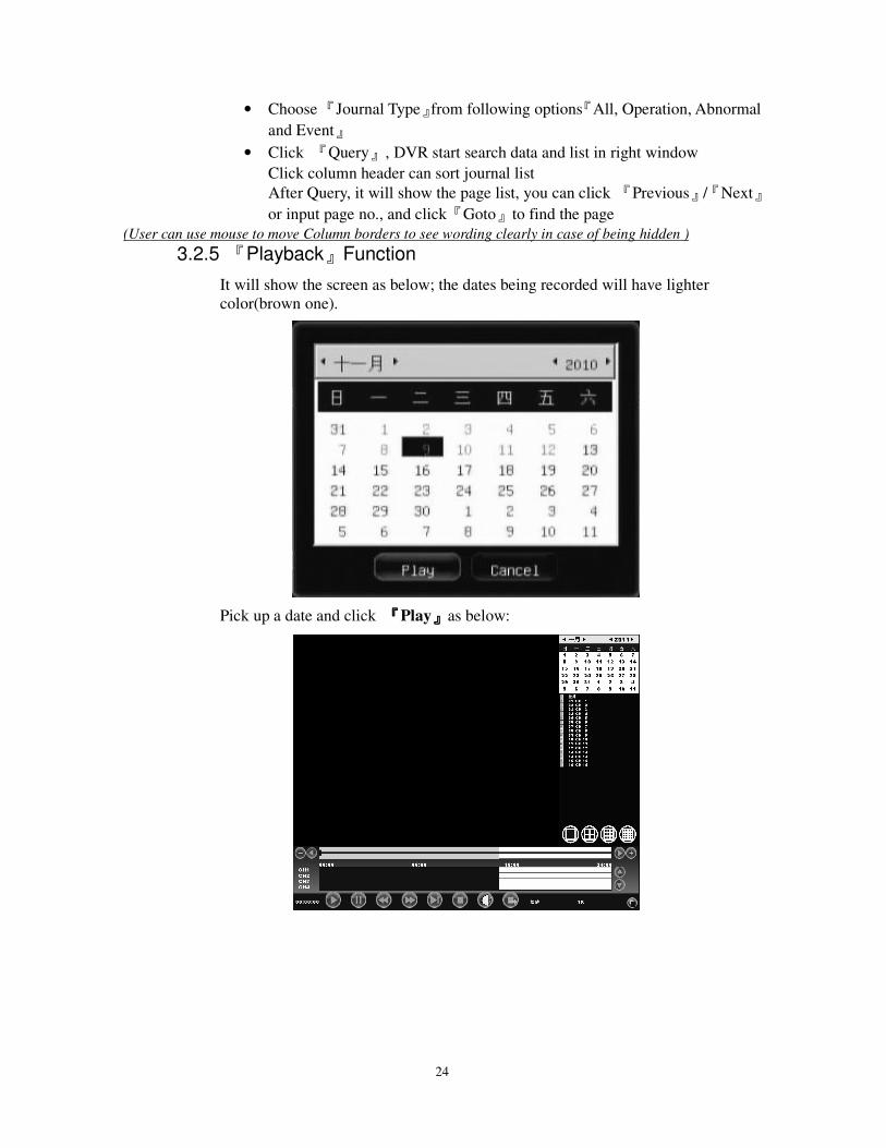
3.2.5 『Playback』Function
It will show the screen as below; the dates being recorded will have lighter
color(brown one).
Pick up a date and click 『『『『Play』』』』as below:
25
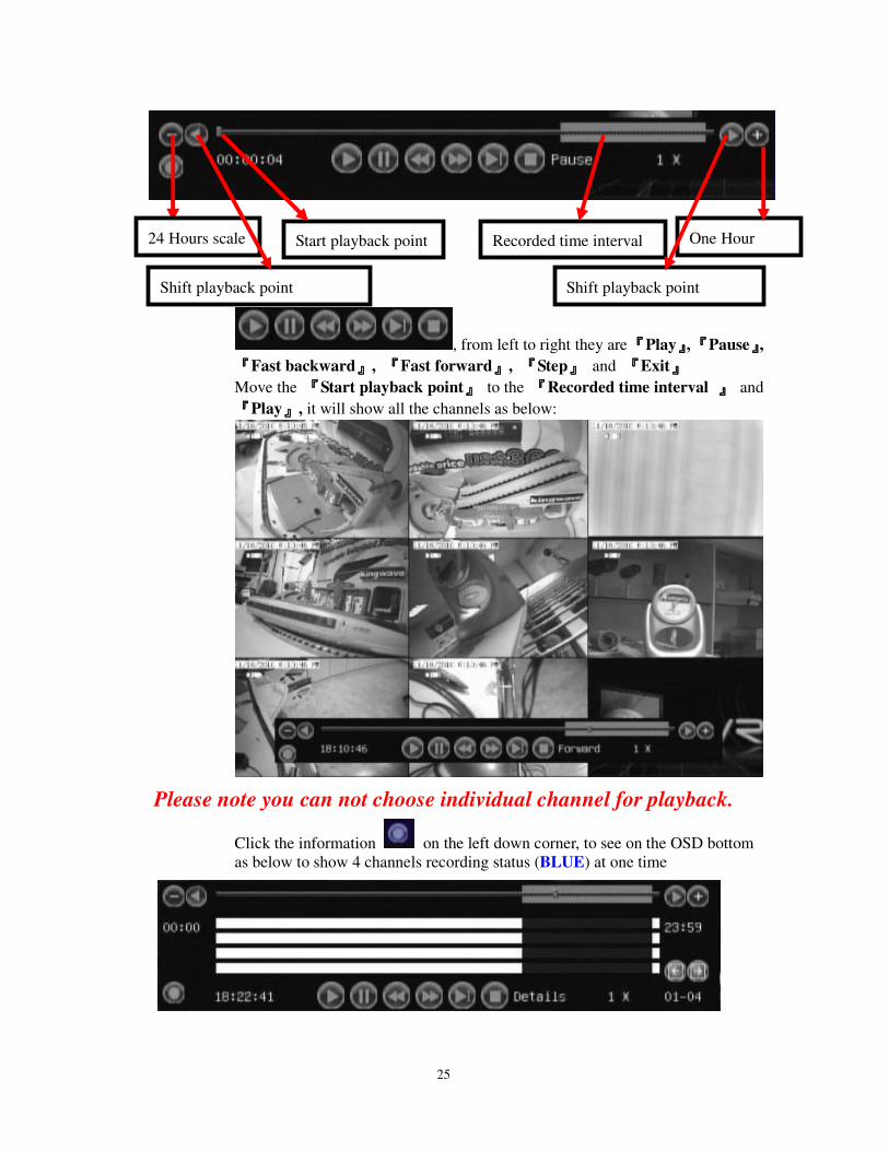
, from left to right they are 『『『『Play』』』』, 『『『『Pause』』』』,
『『『『Fast backward』』』』, 『『『『Fast forward』』』』, 『『『『Step』』』』 and 『『『『Exit』』』』
Move the 『『『『Start playback point』』』』 to the 『『『『Recorded time interval 』』』』 and
『『『『Play』』』』, it will show all the channels as below:
Please note you can not choose individual channel for playback.
Click the information on the left down corner, to see on the OSD bottom
as below to show 4 channels recording status (BLUE) at one time
24 Hours scale Start playback point Recorded time interval One Hour
Shift playback point Shift playback point
26
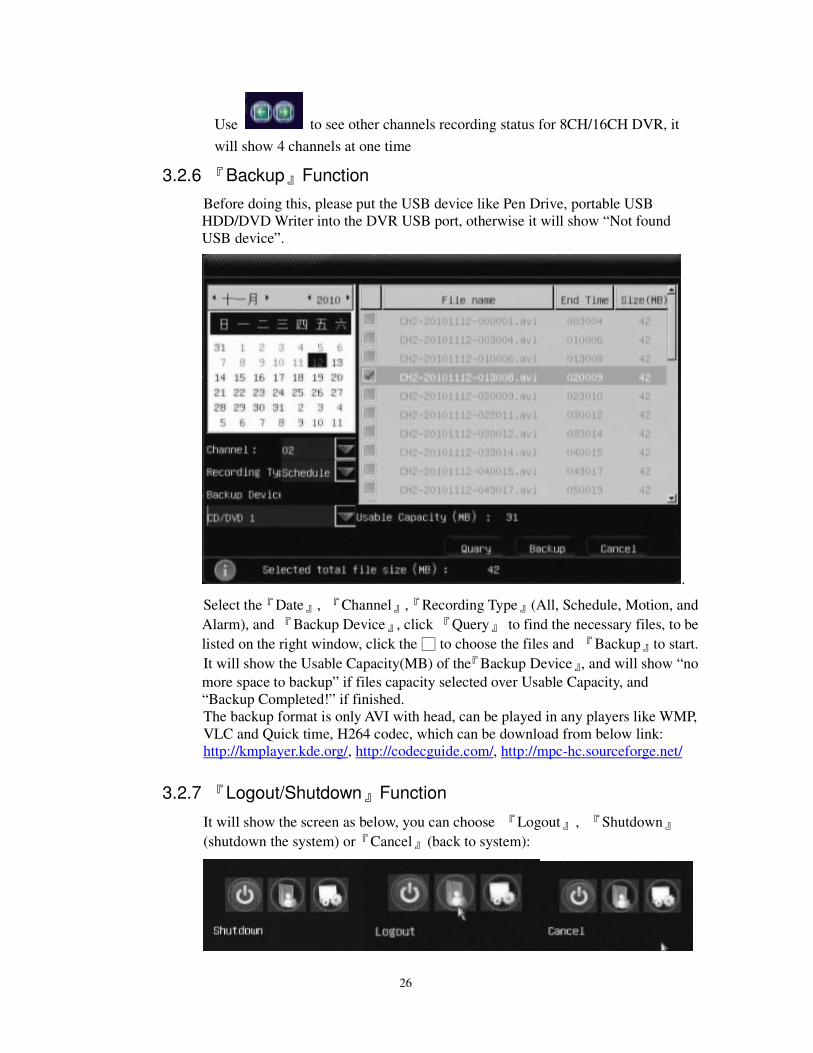
Use to see other channels recording status for 8CH/16CH DVR, it
will show 4 channels at one time
3.2.6 『Backup』Function
Before doing this, please put the USB device like Pen Drive, portable USB
HDD/DVD Writer into the DVR USB port, otherwise it will show “Not found
USB device”.
.
Select the『Date』, 『Channel』,『Recording Type』(All, Schedule, Motion, and
Alarm), and 『Backup Device』, click 『Query』 to find the necessary files, to be
listed on the right window, click the to choose the files and 『Backup』to start.
It will show the Usable Capacity(MB) of the『Backup Device』, and will show “no
more space to backup” if files capacity selected over Usable Capacity, and
“Backup Completed!” if finished.
The backup format is only AVI with head, can be played in any players like WMP,
VLC and Quick time, H264 codec, which can be download from below link:
http://kmplayer.kde.org/, http://codecguide.com/, http://mpc-hc.sourceforge.net/
3.2.7 『Logout/Shutdown』Function
It will show the screen as below, you can choose 『Logout』, 『Shutdown』
(shutdown the system) or『Cancel』(back to system):
27
4 DVR System Configure
4.1 SYSTEM Tab
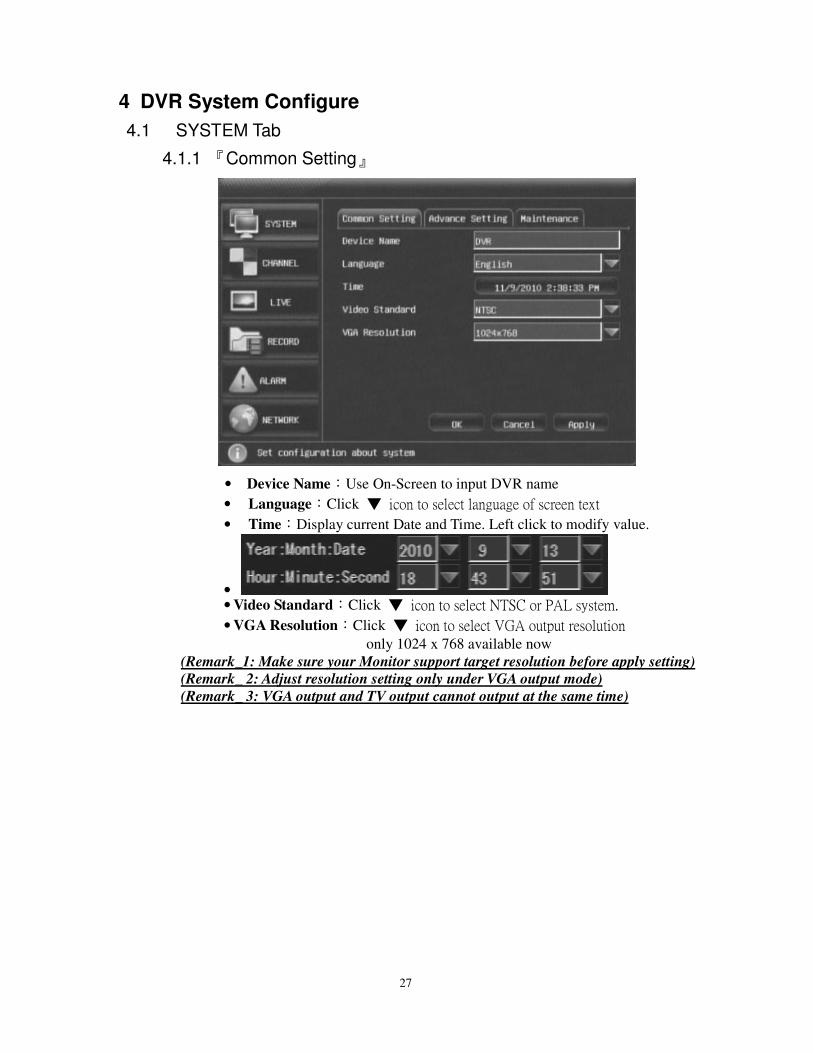
4.1.1 『Common Setting』
• Device Name:Use On-Screen to input DVR name
• Language:Click icon to select language of screen text
• Time:Display current Date and Time. Left click to modify value.
• • Video Standard:Click icon to select NTSC or PAL system.
• VGA Resolution:Click icon to select VGA output resolution only 1024 x 768 available now
(Remark_1: Make sure your Monitor support target resolution before apply setting)
(Remark_ 2: Adjust resolution setting only under VGA output mode)
(Remark_ 3: VGA output and TV output cannot output at the same time)

28
4.1.2 『Advance Setting』
• Time Format:Click icon to select different format
• DST settings:Click 『Set Up』to open sub setup window as below
Set up the DST(Saving Time) Start Time and Stop time so that
system time will be adjusted automatically when matched.
• User Management:Click 『Set Up』to open sub setup window
it also shows user operation authority
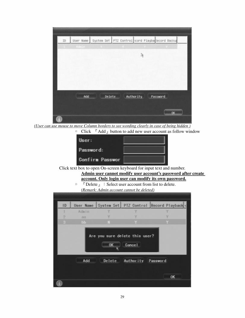
29
(User can use mouse to move Column borders to see wording clearly in case of being hidden )
Click 『Add』button to add new user account as follow window
Click text box to open On-screen keyboard for input text and number.
Admin user cannot modify user account’s password after create
account. Only login user can modify its own password.
『Delete』:Select user account from list to delete.
(Remark: Admin account cannot be deleted)
30
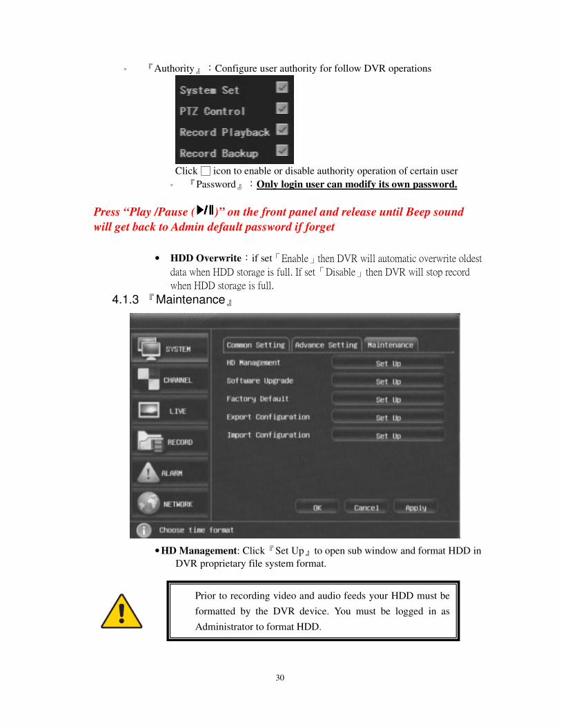
『Authority』:Configure user authority for follow DVR operations
Click icon to enable or disable authority operation of certain user
『Password』:Only login user can modify its own password.
Press “Play /Pause ( )” on the front panel and release until Beep sound
will get back to Admin default password if forget
• HDD Overwrite:if set「Enable」then DVR will automatic overwrite oldest
data when HDD storage is full. If set「Disable」then DVR will stop record
when HDD storage is full.
4.1.3 『Maintenance』
• HD Management: Click『Set Up』to open sub window and format HDD in
DVR proprietary file system format.
Prior to recording video and audio feeds your HDD must be
formatted by the DVR device. You must be logged in as
Administrator to format HDD.
31
• Software Upgrade: Click『Set Up』can open sub windows to upgrade DVR
firmware by USB flash disk.
• Factory Default : get back to factory default setting
• Export Configuration : output this DVR setting to external USB device like
pen drive for other DVR set up use
• Import Configuration : input other DVR setting from external USB device
like pen drive, to save time for set up
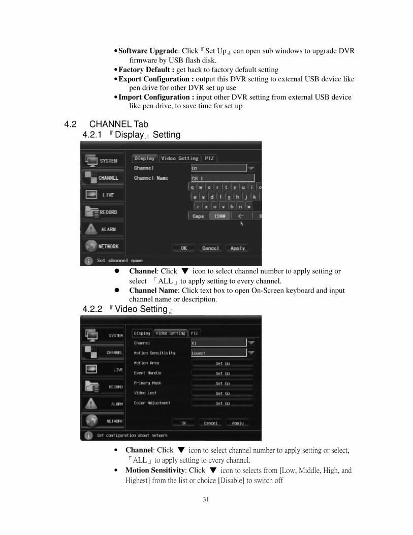
4.2 CHANNEL Tab 4.2.1 『Display』Setting
Channel: Click icon to select channel number to apply setting or
select 「ALL」to apply setting to every channel.
Channel Name: Click text box to open On-Screen keyboard and input
channel name or description.
4.2.2 『Video Setting』
• Channel: Click icon to select channel number to apply setting or select,
「ALL」to apply setting to every channel.
• Motion Sensitivity: Click icon to selects from [Low, Middle, High, and
Highest] from the list or choice [Disable] to switch off
32
motion detection function.
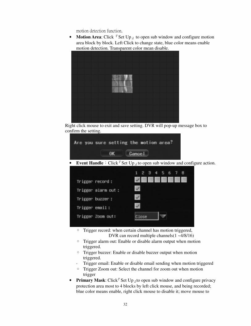
• Motion Area: Click『Set Up』to open sub window and configure motion
area block by block. Left Click to change state, blue color means enable
motion detection. Transparent color mean disable.
Right click mouse to exit and save setting. DVR will pop-up message box to
confirm the setting.
• Event Handle:Click『Set Up』to open sub window and configure action.
Trigger record: when certain channel has motion triggered,
DVR can record multiple channels(1 ~4/8/16)
Trigger alarm out: Enable or disable alarm output when motion
triggered.
Trigger buzzer: Enable or disable buzzer output when motion
triggered.
Trigger email: Enable or disable email sending when motion triggered
Trigger Zoom out: Select the channel for zoom out when motion
trigger
• Primary Mask: Click『Set Up』to open sub window and configure privacy
protection area most to 4 blocks by left click mouse, and being recorded;
blue color means enable, right click mouse to disable it; move mouse to
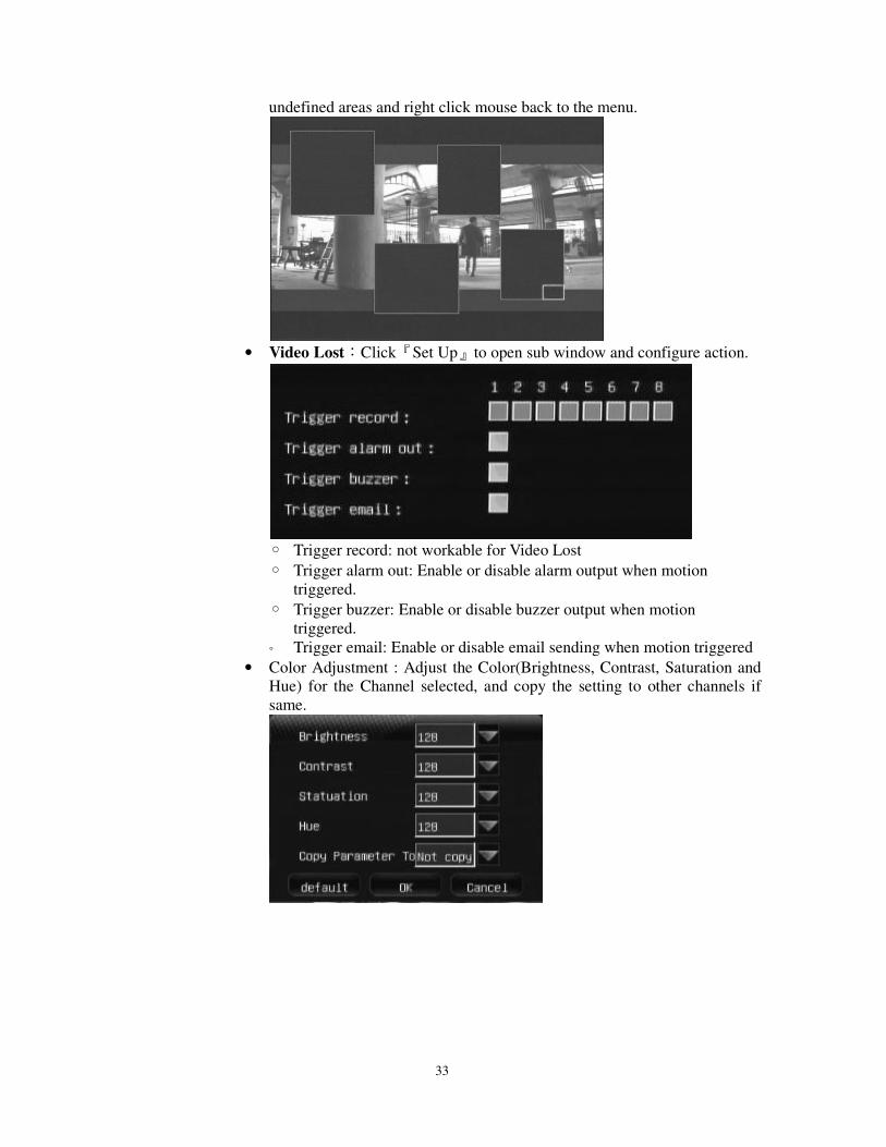
33
undefined areas and right click mouse back to the menu.
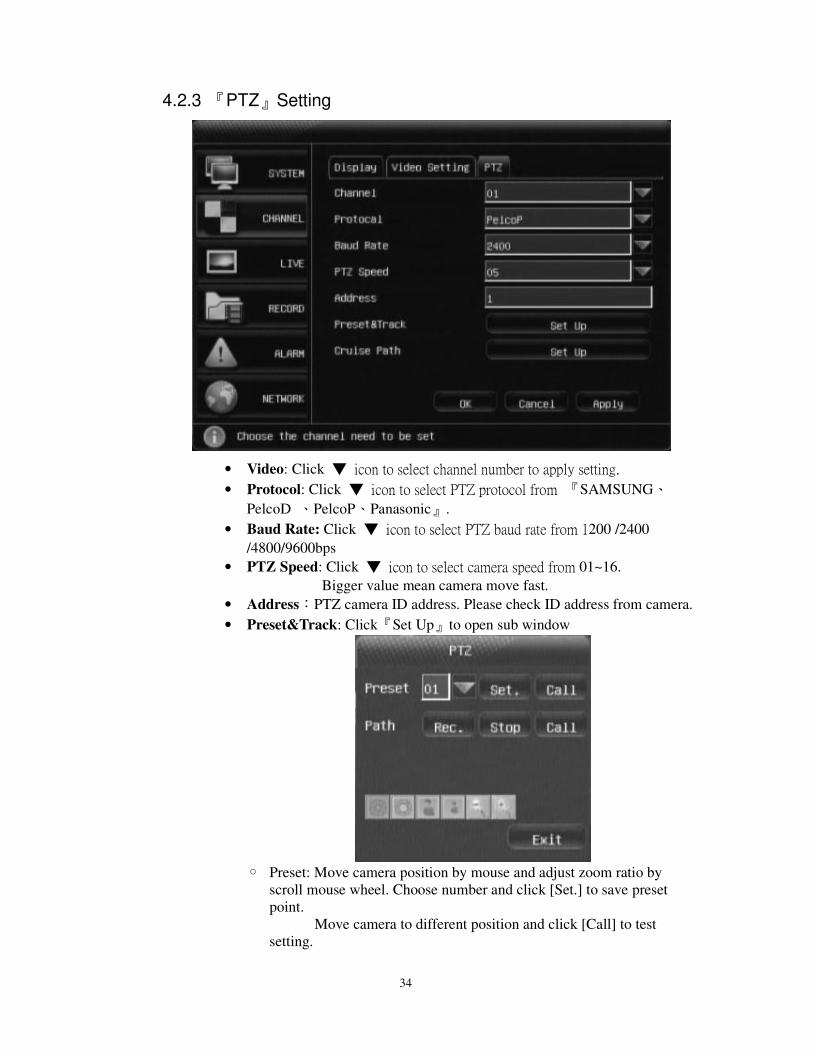
• Video Lost:Click『Set Up』to open sub window and configure action.
Trigger record: not workable for Video Lost
Trigger alarm out: Enable or disable alarm output when motion
triggered.
Trigger buzzer: Enable or disable buzzer output when motion
triggered.
Trigger email: Enable or disable email sending when motion triggered
• Color Adjustment : Adjust the Color(Brightness, Contrast, Saturation and
Hue) for the Channel selected, and copy the setting to other channels if
same.
34
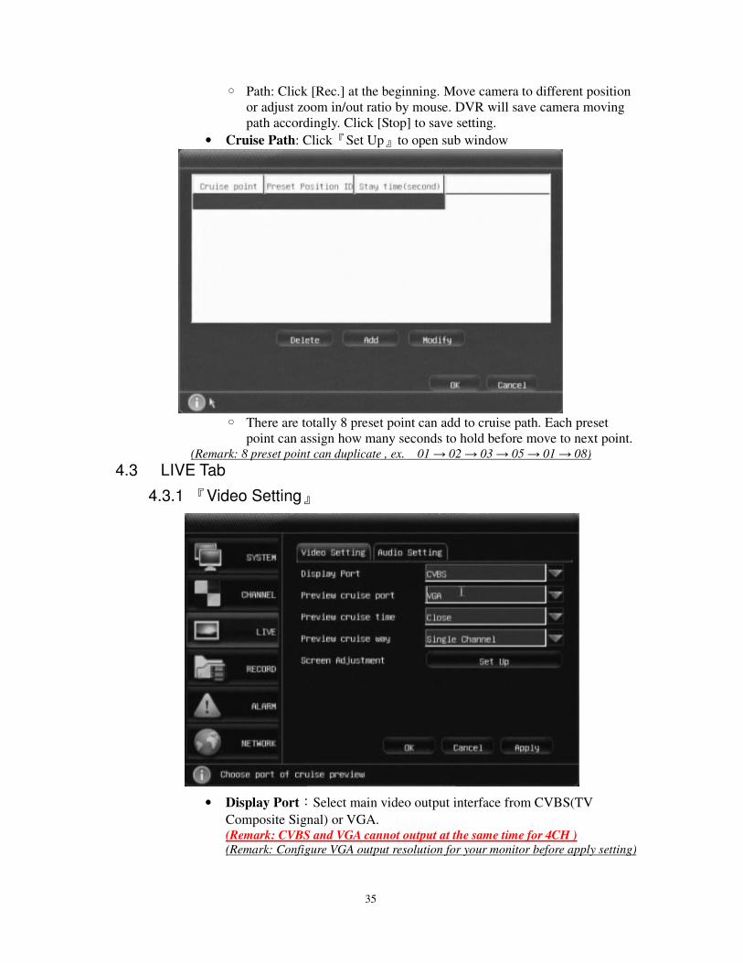
4.2.3 『PTZ』Setting
• Video: Click icon to select channel number to apply setting.
• Protocol: Click icon to select PTZ protocol from 『SAMSUNG、
PelcoD 、PelcoP、Panasonic』.
• Baud Rate: Click icon to select PTZ baud rate from 1200 /2400
/4800/9600bps
• PTZ Speed: Click icon to select camera speed from 01~16.
Bigger value mean camera move fast.
• Address:PTZ camera ID address. Please check ID address from camera.
• Preset&Track: Click『Set Up』to open sub window
Preset: Move camera position by mouse and adjust zoom ratio by
scroll mouse wheel. Choose number and click [Set.] to save preset
point.
Move camera to different position and click [Call] to test
setting.
35
Path: Click [Rec.] at the beginning. Move camera to different position
or adjust zoom in/out ratio by mouse. DVR will save camera moving
path accordingly. Click [Stop] to save setting.
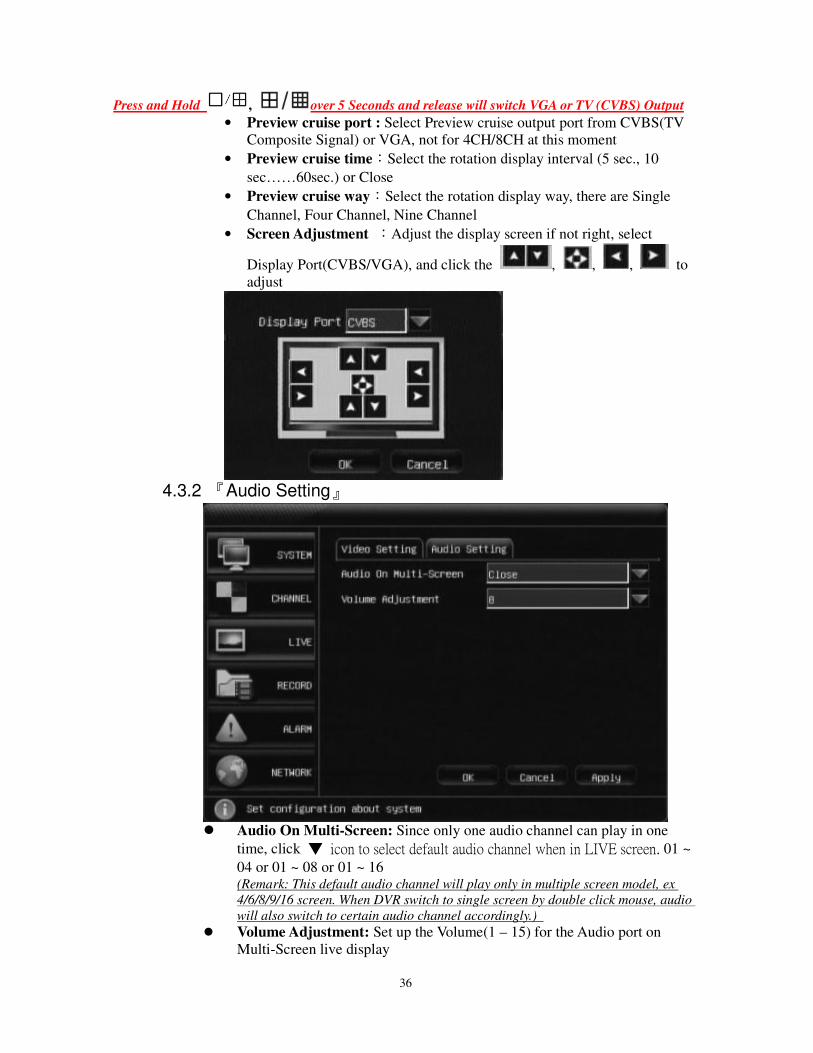
• Cruise Path: Click『Set Up』to open sub window
There are totally 8 preset point can add to cruise path. Each preset
point can assign how many seconds to hold before move to next point. (Remark: 8 preset point can duplicate , ex. 01 → 02 → 03 → 05 → 01 → 08)
4.3 LIVE Tab
4.3.1 『Video Setting』
• Display Port:Select main video output interface from CVBS(TV
Composite Signal) or VGA. (Remark: CVBS and VGA cannot output at the same time for 4CH )
(Remark: Configure VGA output resolution for your monitor before apply setting)
36
Press and Hold , over 5 Seconds and release will switch VGA or TV (CVBS) Output
• Preview cruise port : Select Preview cruise output port from CVBS(TV
Composite Signal) or VGA, not for 4CH/8CH at this moment
• Preview cruise time:Select the rotation display interval (5 sec., 10
sec……60sec.) or Close
• Preview cruise way:Select the rotation display way, there are Single
Channel, Four Channel, Nine Channel
• Screen Adjustment :Adjust the display screen if not right, select
Display Port(CVBS/VGA), and click the , , , to
adjust
4.3.2 『Audio Setting』
Audio On Multi-Screen: Since only one audio channel can play in one
time, click icon to select default audio channel when in LIVE screen. 01 ~
04 or 01 ~ 08 or 01 ~ 16 (Remark: This default audio channel will play only in multiple screen model, ex
4/6/8/9/16 screen. When DVR switch to single screen by double click mouse, audio
will also switch to certain audio channel accordingly.)
Volume Adjustment: Set up the Volume(1 – 15) for the Audio port on
Multi-Screen live display
37
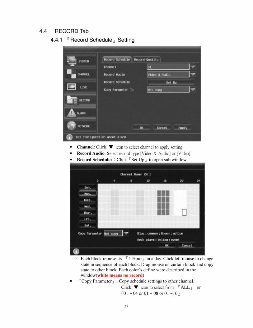
4.4 RECORD Tab
4.4.1 『Record Schedule』Setting
• Channel: Click icon to select channel to apply setting.
• Record Audio: Select record type [Video & Audio] or [Video].
• Record Schedule::Click『Set Up』to open sub window
Each block represents 『1 Hour』in a day. Click left mouse to change
state in sequence of each block. Drag mouse on curtain block and copy
state to other block. Each color’s define were described in the
window(white means no record)
• 『Copy Parameter』: Copy schedule settings to other channel.
Click icon to select from 『ALL』 or
『01 ~ 04 or 01 ~ 08 or 01 ~16』
38
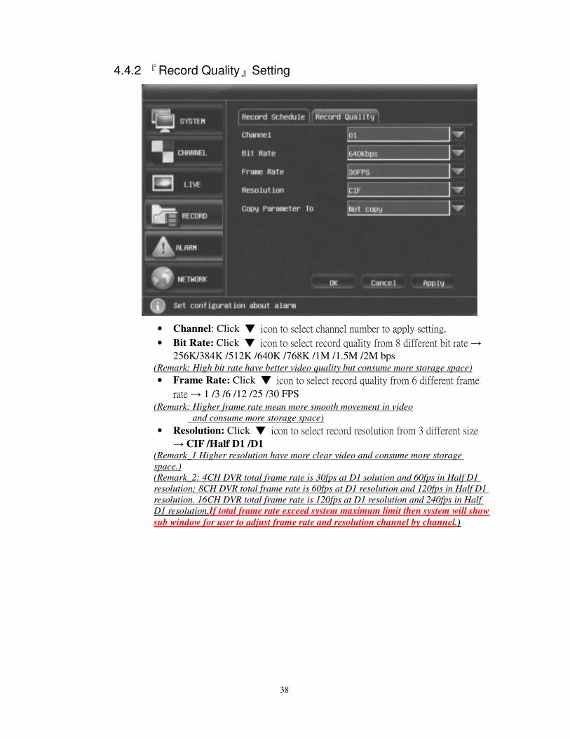
4.4.2 『Record Quality』Setting
• Channel: Click icon to select channel number to apply setting.
• Bit Rate: Click icon to select record quality from 8 different bit rate →
256K/384K /512K /640K /768K /1M /1.5M /2M bps (Remark: High bit rate have better video quality but consume more storage space)
• Frame Rate: Click icon to select record quality from 6 different frame
rate → 1 /3 /6 /12 /25 /30 FPS
(Remark: Higher frame rate mean more smooth movement in video
and consume more storage space)
• Resolution: Click icon to select record resolution from 3 different size
→ CIF /Half D1 /D1 (Remark_1 Higher resolution have more clear video and consume more storage
space.)
(Remark_2: 4CH DVR total frame rate is 30fps at D1 solution and 60fps in Half D1
resolution; 8CH DVR total frame rate is 60fps at D1 resolution and 120fps in Half D1
resolution. 16CH DVR total frame rate is 120fps at D1 resolution and 240fps in Half
D1 resolution.If total frame rate exceed system maximum limit then system will show
sub window for user to adjust frame rate and resolution channel by channel.)
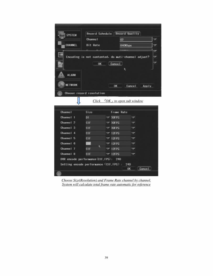
39
Click 『OK』to open sub window
Choose Size(Resolution) and Frame Rate channel by channel.
System will calculate total frame rate automatic for reference
40
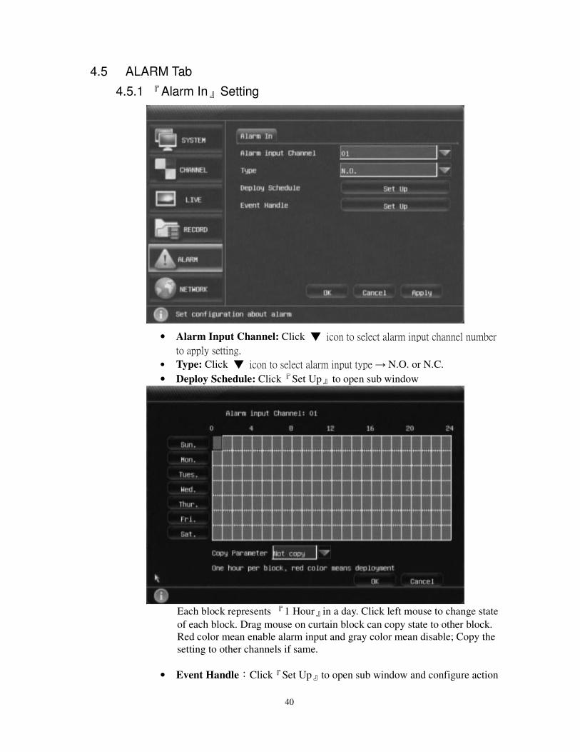
4.5 ALARM Tab
4.5.1 『Alarm In』Setting
• Alarm Input Channel: Click icon to select alarm input channel number
to apply setting.
• Type: Click icon to select alarm input type → N.O. or N.C.
• Deploy Schedule: Click『Set Up』to open sub window
Each block represents 『1 Hour』in a day. Click left mouse to change state
of each block. Drag mouse on curtain block can copy state to other block.
Red color mean enable alarm input and gray color mean disable; Copy the
setting to other channels if same.
• Event Handle:Click『Set Up』to open sub window and configure action
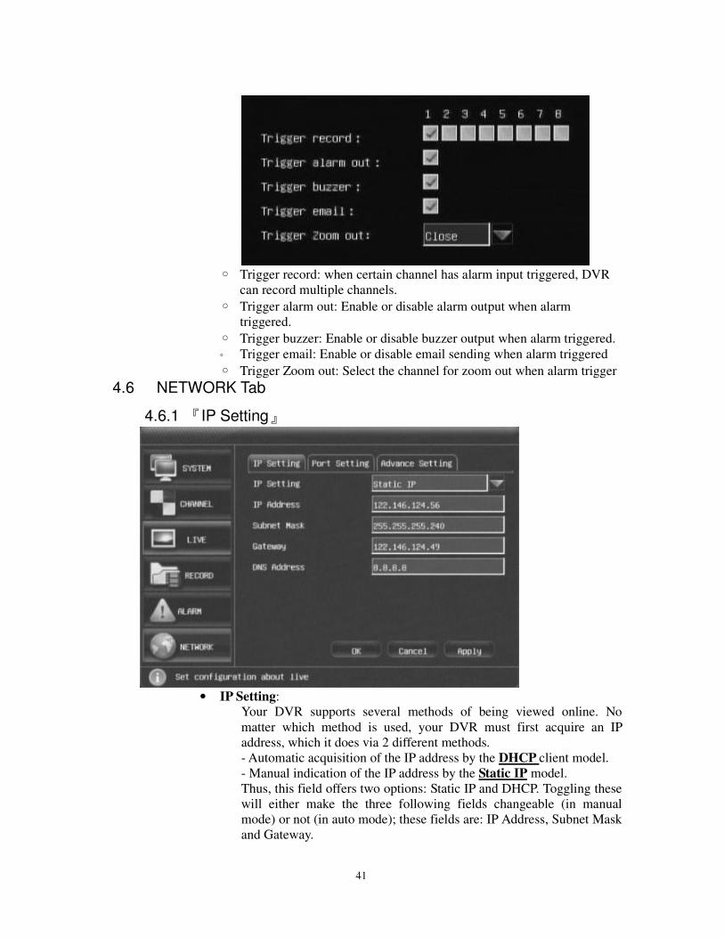
41
Trigger record: when certain channel has alarm input triggered, DVR
can record multiple channels.
Trigger alarm out: Enable or disable alarm output when alarm
triggered.
Trigger buzzer: Enable or disable buzzer output when alarm triggered.
Trigger email: Enable or disable email sending when alarm triggered
Trigger Zoom out: Select the channel for zoom out when alarm trigger
4.6 NETWORK Tab
4.6.1 『IP Setting』
• IP Setting:
Your DVR supports several methods of being viewed online. No
matter which method is used, your DVR must first acquire an IP
address, which it does via 2 different methods.
- Automatic acquisition of the IP address by the DHCP client model.
- Manual indication of the IP address by the Static IP model.
Thus, this field offers two options: Static IP and DHCP. Toggling these
will either make the three following fields changeable (in manual
mode) or not (in auto mode); these fields are: IP Address, Subnet Mask
and Gateway.
42
For exact data on your network and explanation of network settings,
please contact your network administrator or Internet service provider.
• IP Address/Subnet Mask/Gateway/DNS Address:Display current one.
If choose Static IP mode, click text box to input them by On-screen
keyboard.
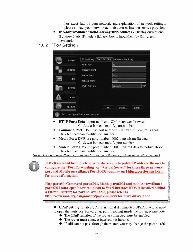
4.6.2 『Port Setting』
• HTTP Port: Default port number is 80 for any web browser.
Click text box can modify port number.
• Command Port: DVR use port number: 6001 transmit control signal.
Click text box can modify port number.
• Media Port: DVR use port number: 6002 transmit media data.
Click text box can modify port number.
• Mobile Port: DVR use port number: 6003 transmit data to mobile phone.
Click text box can modify port number. (Remark: mobile surveillance software need to configure the same port number as above setting)
UPnP Setting: Enable UPnP function if it connected UPnP router, no need
to open the ports(port forwarding, port mapping) inside the router, please note:
The UPnP function of the router connected must be enabled
The router must connect internet, not intranet
If still can not pass through the router, you may change the port no.(80,
If DVR installed behind a Router to share a single public IP address. Be sure to
configure the “Port Forwarding” or “Virtual Server” for those three network
port and Mobile surveillance Port:6003; you may surf http://portforward.com
for more information.
Http port:80, Command port:6001, Media port:6002 and mobile surveillance
port:6003 must open/allow to upload to WAN interface if DVR installed behind
a Firewall server; for port no. available, please refer to
http://www.iana.org/assignments/port-numbers for more information
43
6001, 6002, 6003) and try again .
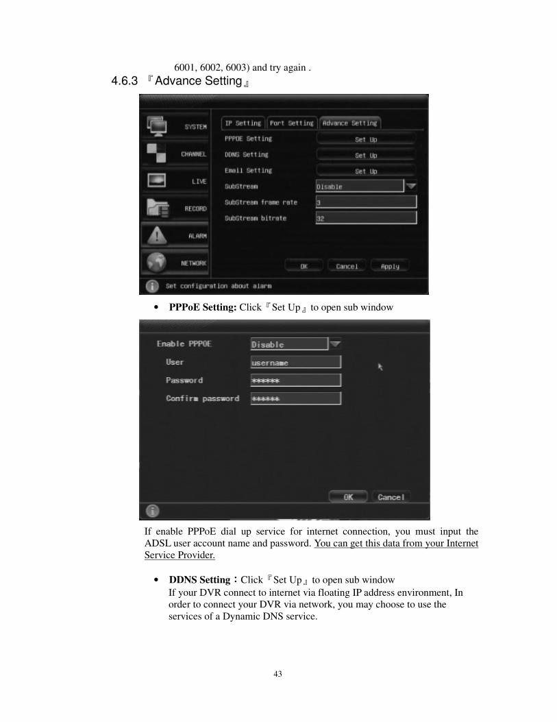
4.6.3 『Advance Setting』
• PPPoE Setting: Click『Set Up』to open sub window
If enable PPPoE dial up service for internet connection, you must input the
ADSL user account name and password. You can get this data from your Internet
Service Provider.
• DDNS Setting::::Click『Set Up』to open sub window
If your DVR connect to internet via floating IP address environment, In
order to connect your DVR via network, you may choose to use the
services of a Dynamic DNS service.
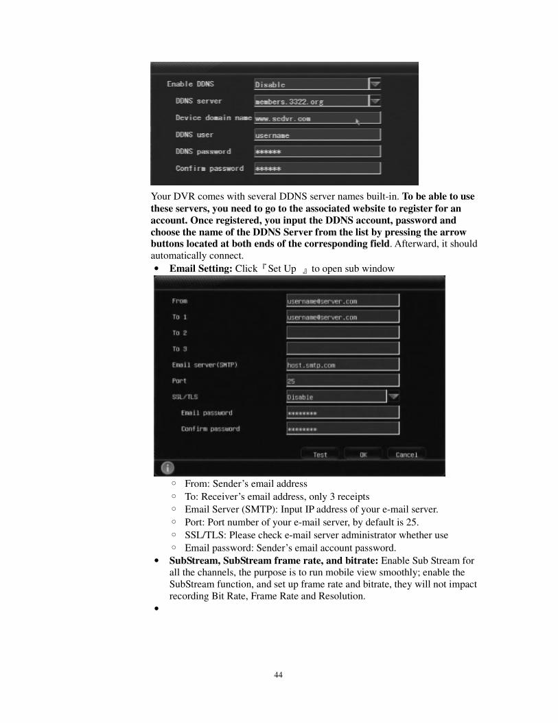
44
Your DVR comes with several DDNS server names built-in. To be able to use
these servers, you need to go to the associated website to register for an
account. Once registered, you input the DDNS account, password and
choose the name of the DDNS Server from the list by pressing the arrow buttons located at both ends of the corresponding field. Afterward, it should
automatically connect.
• Email Setting: Click『Set Up 』to open sub window
From: Sender’s email address
To: Receiver’s email address, only 3 receipts
Email Server (SMTP): Input IP address of your e-mail server.
Port: Port number of your e-mail server, by default is 25.
SSL/TLS: Please check e-mail server administrator whether use
Email password: Sender’s email account password.
• SubStream, SubStream frame rate, and bitrate: Enable Sub Stream for
all the channels, the purpose is to run mobile view smoothly; enable the
SubStream function, and set up frame rate and bitrate, they will not impact
recording Bit Rate, Frame Rate and Resolution.
•
45
5 DVR Network Surveillance with Web Browser
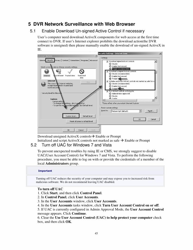
5.1 Enable Download Un-signed Active Control if necessary
User’s computer need download ActiveX components for web access at the first time
connect to DVR. If user’s Internet explorer prohibits the download action(the DVR
software is unsigned) then please manually enable the download of un-signed ActiveX in
IE.
Download unsigned ActiveX controls Enable or Prompt
Initialized and script ActiveX controls not marked as safe Enable or Prompt
5.2 Turn off UAC for Windows 7 and Vista
To prevent unexpected troubles by ruing IE or CMS, we strongly suggest to disable
UAC(User Account Control) for Windows 7 and Vista. To perform the following
procedure, you must be able to log on with or provide the credentials of a member of the
local Administrators group.
Important
Turning off UAC reduces the security of your computer and may expose you to increased risk from
malicious software. We do not recommend leaving UAC disabled.
To turn off UAC 1. Click Start, and then click Control Panel.
2. In Control Panel, click User Accounts.
3. In the User Accounts window, click User Accounts.
4. In the User Accounts tasks window, click Turn User Account Control on or off.
5. If UAC is currently configured in Admin Approval Mode, the User Account Control
message appears. Click Continue.
6. Clear the Use User Account Control (UAC) to help protect your computer check
box, and then click OK.
46
7. Click Restart Now to apply the change right away, or click Restart Later and close
the User Accounts tasks window
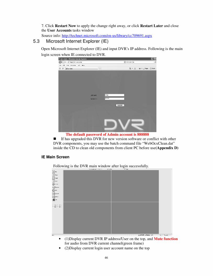
Source info: http://technet.microsoft.com/en-us/library/cc709691.aspx 5.3 Microsoft Internet Explorer (IE)
Open Microsoft Internet Explorer (IE) and input DVR’s IP address. Following is the main
login screen when IE connected to DVR.
The default password of Admin account is 888888
If has upgraded this DVR for new version software or conflict with other
DVR components, you may use the batch command file “WebOcxClean.dat”
inside the CD to clean old components from client PC before use(Appendix D)
IE Main Screen
Following is the DVR main window after login successfully.
• (1)Display current DVR IP address/User on the top, and Mute function
for audio from DVR current channel(green frame)
• (2)Display current login user account name on the top
47
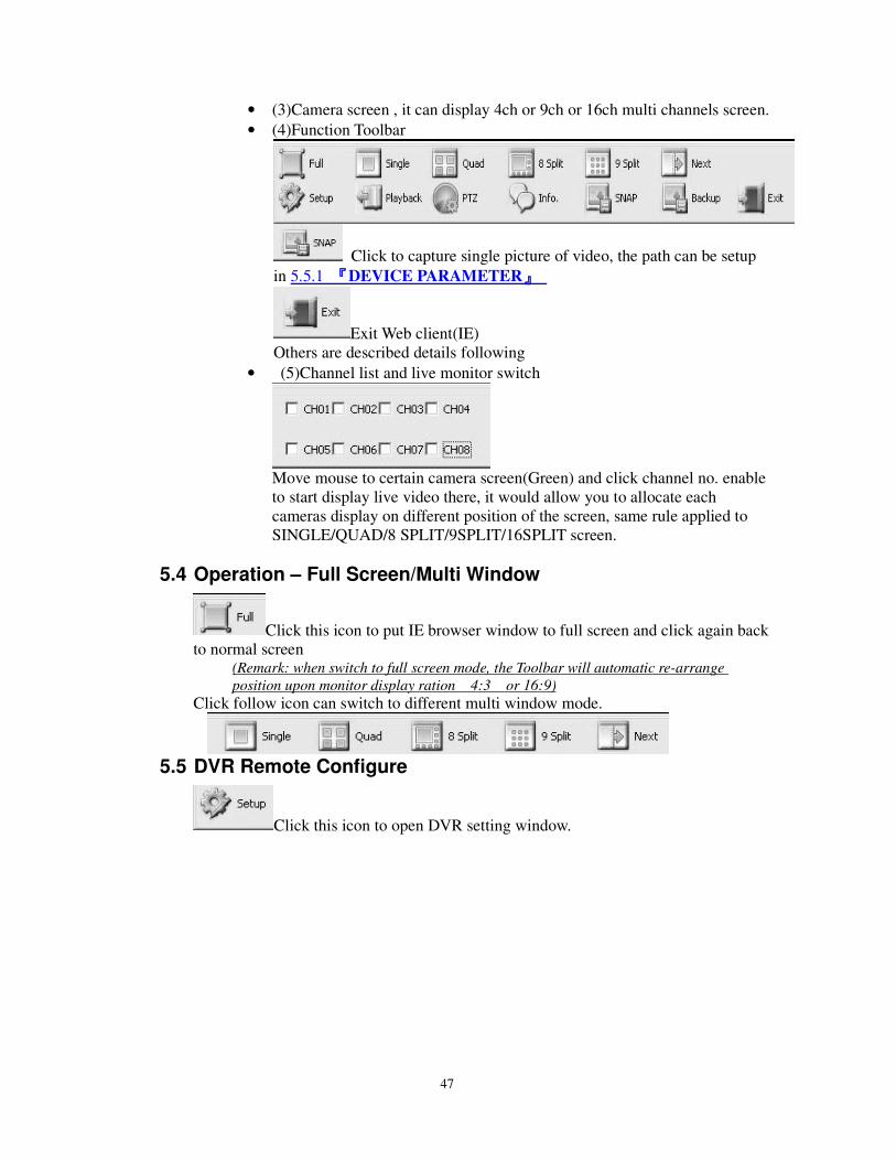
• (3)Camera screen , it can display 4ch or 9ch or 16ch multi channels screen.
• (4)Function Toolbar
Click to capture single picture of video, the path can be setup
in 5.5.1 『『『『DEVICE PARAMETER』』』』
Exit Web client(IE)
Others are described details following
• (5)Channel list and live monitor switch
Move mouse to certain camera screen(Green) and click channel no. enable
to start display live video there, it would allow you to allocate each
cameras display on different position of the screen, same rule applied to
SINGLE/QUAD/8 SPLIT/9SPLIT/16SPLIT screen.
5.4 Operation – Full Screen/Multi Window
Click this icon to put IE browser window to full screen and click again back
to normal screen (Remark: when switch to full screen mode, the Toolbar will automatic re-arrange
position upon monitor display ration 4:3 or 16:9)
Click follow icon can switch to different multi window mode.
5.5 DVR Remote Configure
Click this icon to open DVR setting window.
48
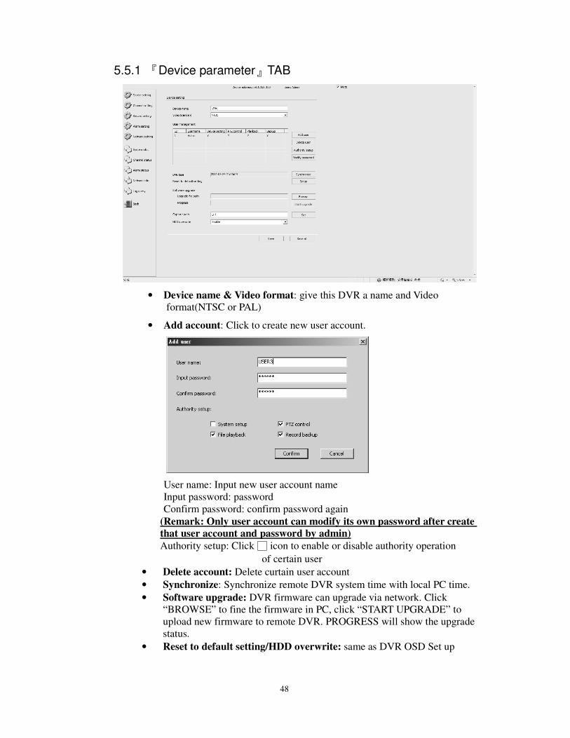
5.5.1 『Device parameter』TAB
• Device name & Video format: give this DVR a name and Video
format(NTSC or PAL)
• Add account: Click to create new user account.
User name: Input new user account name
Input password: password
Confirm password: confirm password again
(Remark: Only user account can modify its own password after create
that user account and password by admin)
Authority setup: Click icon to enable or disable authority operation
of certain user
• Delete account: Delete curtain user account
• Synchronize: Synchronize remote DVR system time with local PC time.
• Software upgrade: DVR firmware can upgrade via network. Click
“BROWSE” to fine the firmware in PC, click “START UPGRADE” to
upload new firmware to remote DVR. PROGRESS will show the upgrade
status.
• Reset to default setting/HDD overwrite: same as DVR OSD Set up
49
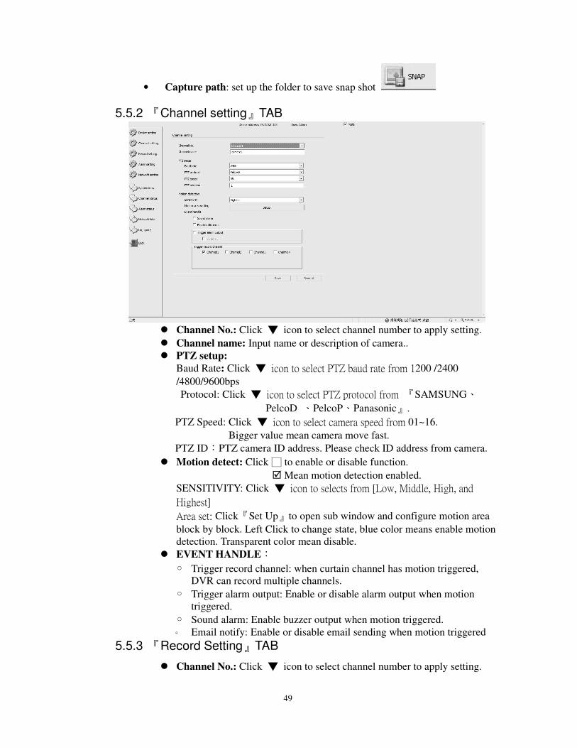
• Capture path: set up the folder to save snap shot
5.5.2 『Channel setting』TAB
Channel No.: Click icon to select channel number to apply setting.
Channel name: Input name or description of camera..
PTZ setup:
Baud Rate: Click icon to select PTZ baud rate from 1200 /2400
/4800/9600bps
Protocol: Click icon to select PTZ protocol from 『SAMSUNG、
PelcoD 、PelcoP、Panasonic』.
PTZ Speed: Click icon to select camera speed from 01~16.
Bigger value mean camera move fast.
PTZ ID:PTZ camera ID address. Please check ID address from camera.
Motion detect: Click to enable or disable function.
Mean motion detection enabled.
SENSITIVITY: Click icon to selects from [Low, Middle, High, and
Highest]
Area set: Click『Set Up』to open sub window and configure motion area
block by block. Left Click to change state, blue color means enable motion
detection. Transparent color mean disable.
EVENT HANDLE:
Trigger record channel: when curtain channel has motion triggered,
DVR can record multiple channels.
Trigger alarm output: Enable or disable alarm output when motion
triggered.
Sound alarm: Enable buzzer output when motion triggered.
Email notify: Enable or disable email sending when motion triggered
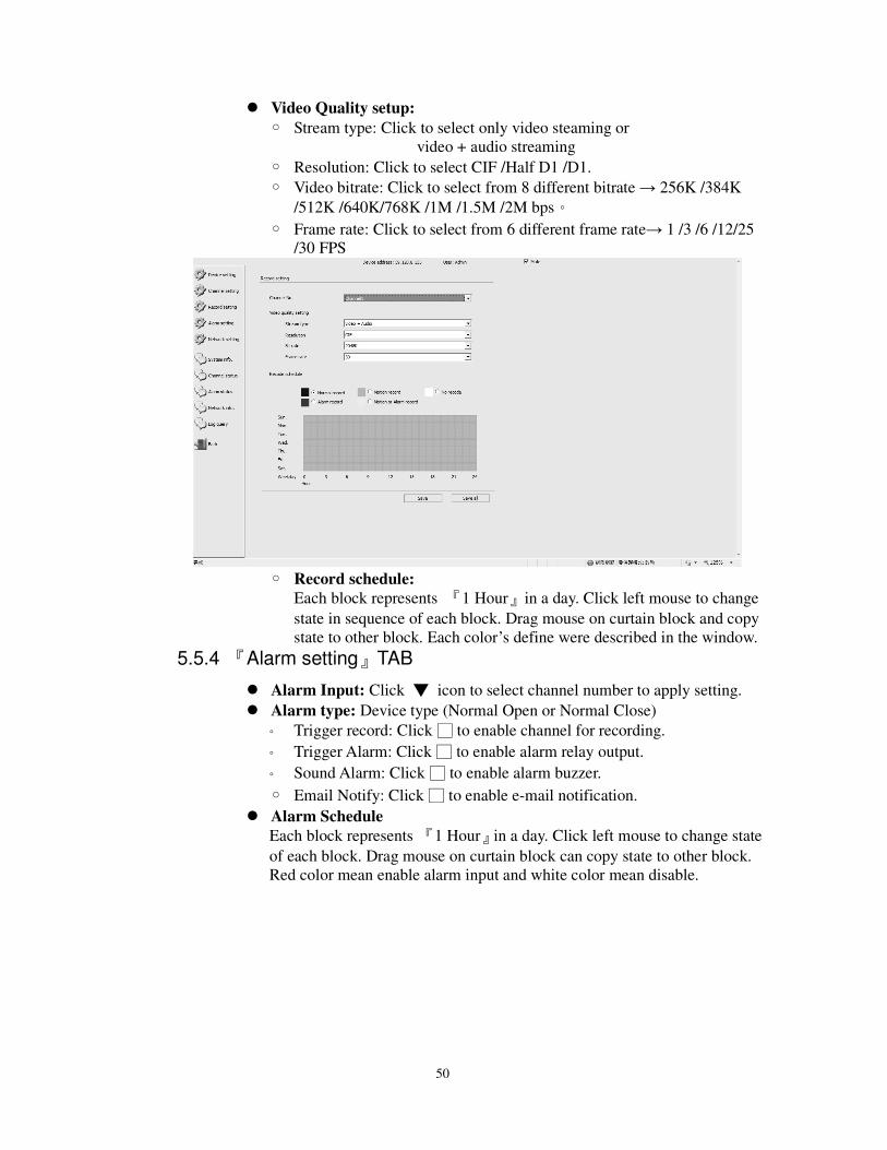
5.5.3 『Record Setting』TAB
Channel No.: Click icon to select channel number to apply setting.
50
Video Quality setup:
Stream type: Click to select only video steaming or
video + audio streaming
Resolution: Click to select CIF /Half D1 /D1.
Video bitrate: Click to select from 8 different bitrate → 256K /384K
/512K /640K/768K /1M /1.5M /2M bps。
Frame rate: Click to select from 6 different frame rate→ 1 /3 /6 /12/25
/30 FPS
Record schedule:
Each block represents 『1 Hour』in a day. Click left mouse to change
state in sequence of each block. Drag mouse on curtain block and copy
state to other block. Each color’s define were described in the window.
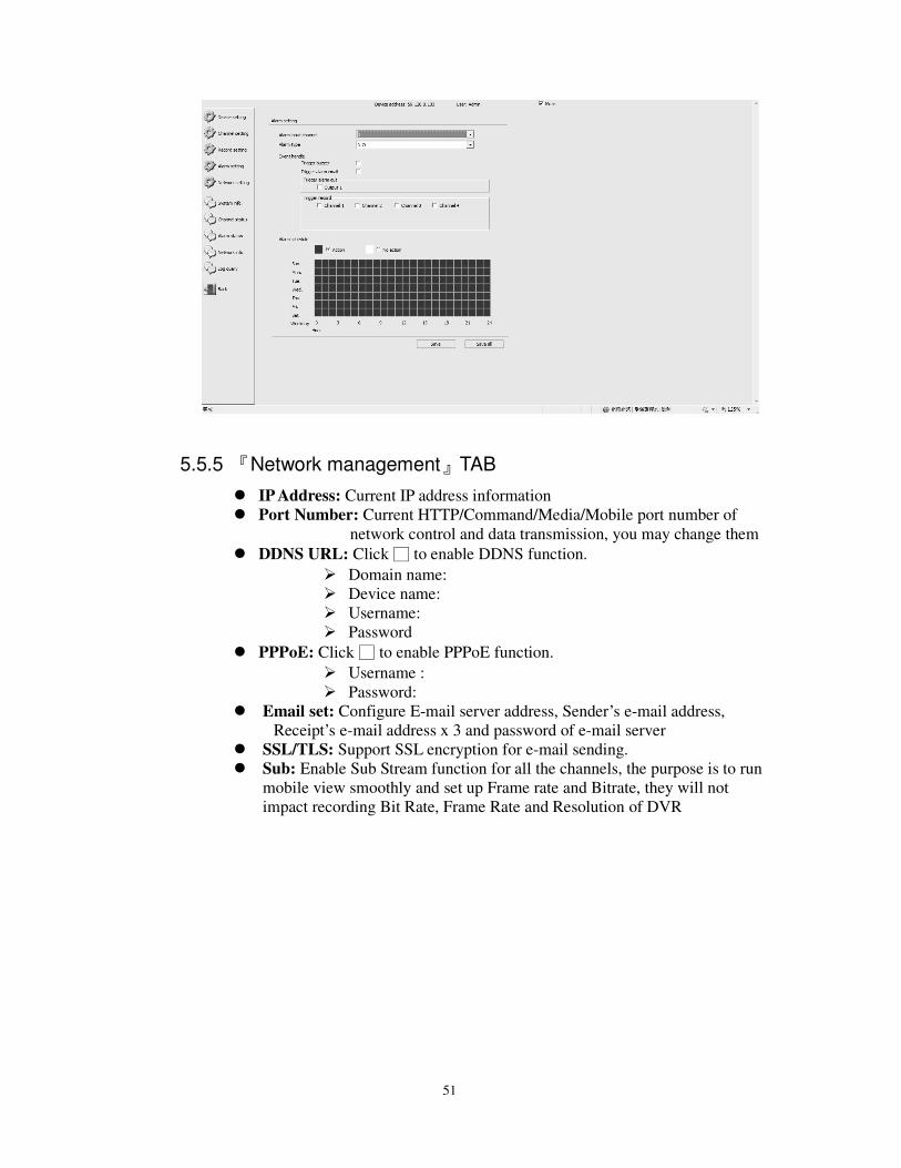
5.5.4 『Alarm setting』TAB
Alarm Input: Click icon to select channel number to apply setting.
Alarm type: Device type (Normal Open or Normal Close)
Trigger record: Click to enable channel for recording.
Trigger Alarm: Click to enable alarm relay output.
Sound Alarm: Click to enable alarm buzzer.
Email Notify: Click to enable e-mail notification.
Alarm Schedule
Each block represents 『1 Hour』in a day. Click left mouse to change state
of each block. Drag mouse on curtain block can copy state to other block.
Red color mean enable alarm input and white color mean disable.
51
5.5.5 『Network management』TAB
IP Address: Current IP address information
Port Number: Current HTTP/Command/Media/Mobile port number of
network control and data transmission, you may change them
DDNS URL: Click to enable DDNS function.
Domain name:
Device name:
Username:
Password
PPPoE: Click to enable PPPoE function.
Username :
Password:
Email set: Configure E-mail server address, Sender’s e-mail address,
Receipt’s e-mail address x 3 and password of e-mail server
SSL/TLS: Support SSL encryption for e-mail sending.
Sub: Enable Sub Stream function for all the channels, the purpose is to run
mobile view smoothly and set up Frame rate and Bitrate, they will not
impact recording Bit Rate, Frame Rate and Resolution of DVR
52
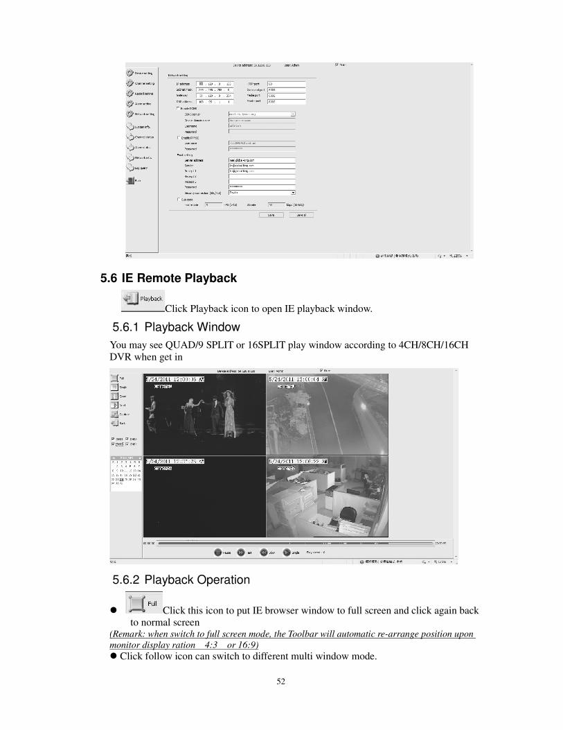
5.6 IE Remote Playback
Click Playback icon to open IE playback window.
5.6.1 Playback Window
You may see QUAD/9 SPLIT or 16SPLIT play window according to 4CH/8CH/16CH
DVR when get in
5.6.2 Playback Operation
Click this icon to put IE browser window to full screen and click again back
to normal screen (Remark: when switch to full screen mode, the Toolbar will automatic re-arrange position upon
monitor display ration 4:3 or 16:9)
Click follow icon can switch to different multi window mode.
53
Click to stop playback and switch live preview model.
Click to capture single picture of playback video, the path can be setup in
5.5.1 『『『『DEVICE PARAMETER』』』』 (Capture path)
Playback by Date and Channel: Choose Date and Channels as beow
Click to time bar to start playback, the grey area on the time bar indicate recording
intervals for playback
While in playback, you can operate Pause/Play, Fast/Slow(x4, x2, x1, 1/2, x1/4, x1/8,
x1/16) and Single(frame) functions
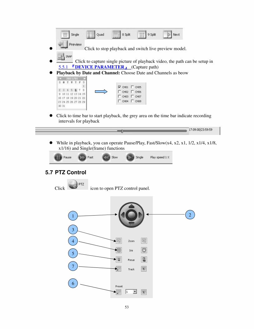
5.7 PTZ Control
Click icon to open PTZ control panel.
5
2
4
1
3
6
7
54
• 1 → Control PTZ camera moving direction.
• 2 → Configure PTZ camera moving speed. ( Increase green box to speed up)
• 3 → Control PTZ camera Zoom In and Zoom Out
• 4 → Adjust PTZ camera Iris
• 5 → Adjust PTZ camera Focus (Video Clarity)
• 6 → Configure 1~128 number of Preset point. Click save and to call.
• 7 → Click open Track setting window. Click to call.
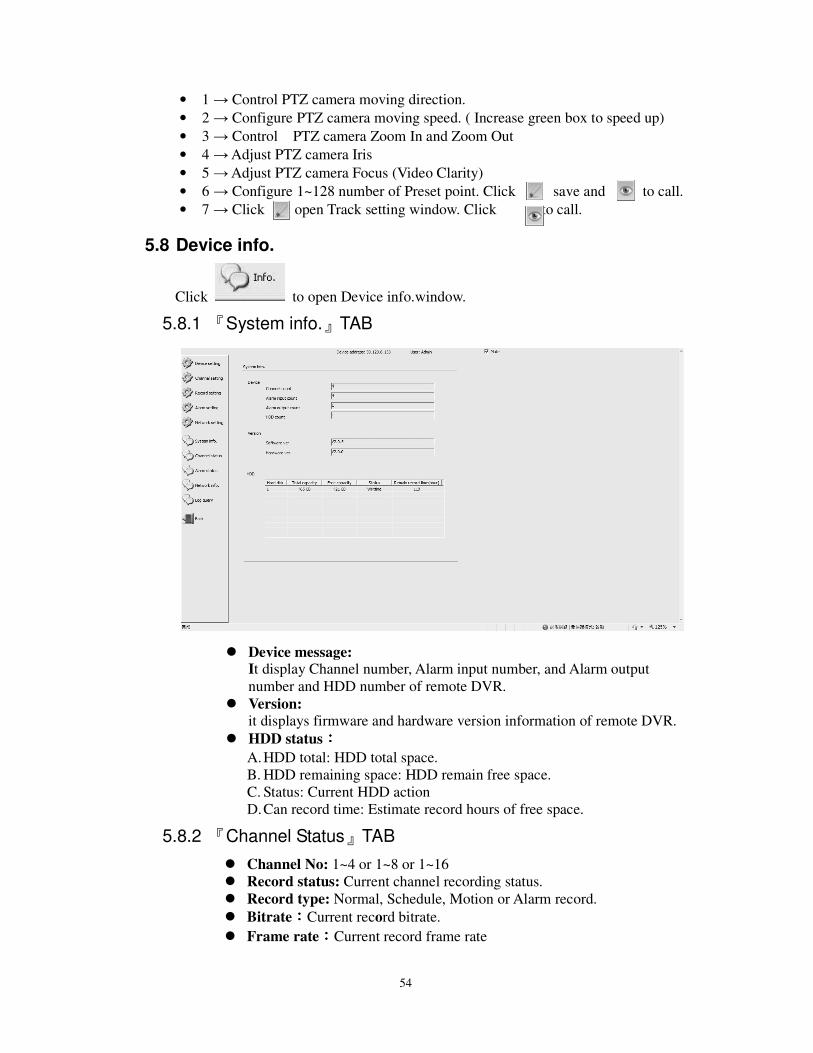
5.8 Device info.
Click to open Device info.window.
5.8.1 『System info.』TAB
Device message: It display Channel number, Alarm input number, and Alarm output
number and HDD number of remote DVR.
Version:
it displays firmware and hardware version information of remote DVR.
HDD status::::
A. HDD total: HDD total space.
B. HDD remaining space: HDD remain free space.
C. Status: Current HDD action
D. Can record time: Estimate record hours of free space.
5.8.2 『Channel Status』TAB
Channel No: 1~4 or 1~8 or 1~16
Record status: Current channel recording status.
Record type: Normal, Schedule, Motion or Alarm record.
Bitrate::::Current record bitrate.
Frame rate::::Current record frame rate
55
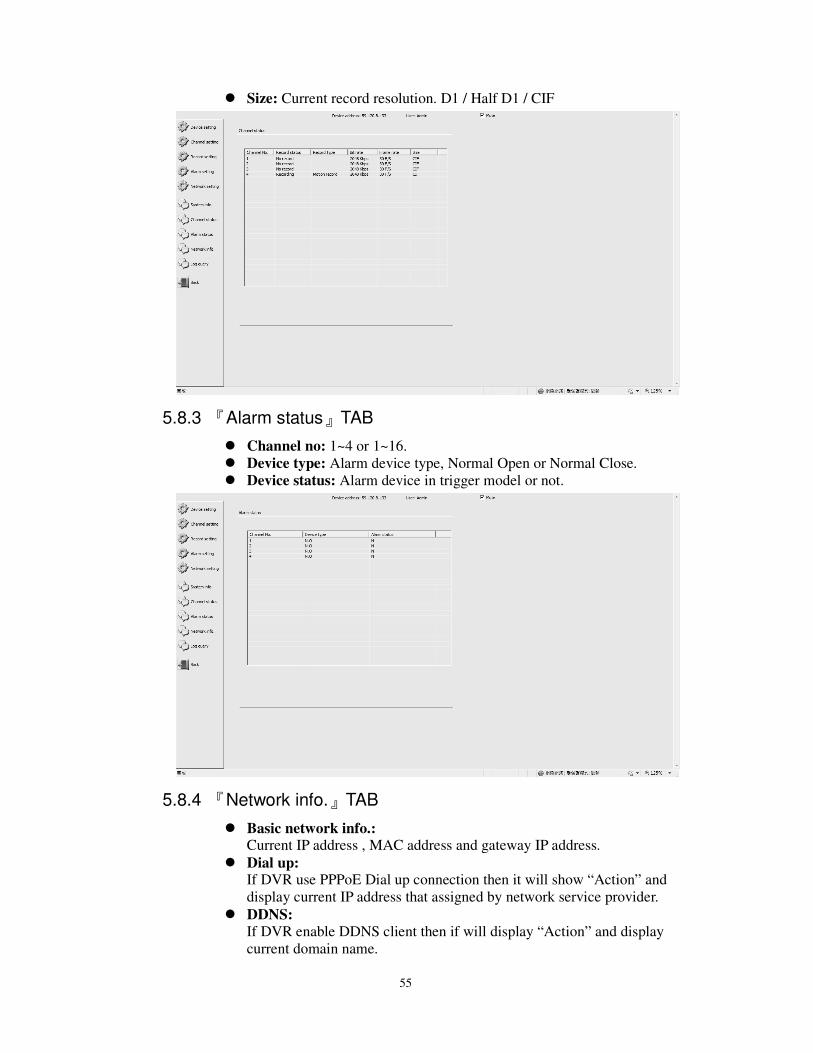
Size: Current record resolution. D1 / Half D1 / CIF
5.8.3 『Alarm status』TAB
Channel no: 1~4 or 1~16.
Device type: Alarm device type, Normal Open or Normal Close.
Device status: Alarm device in trigger model or not.
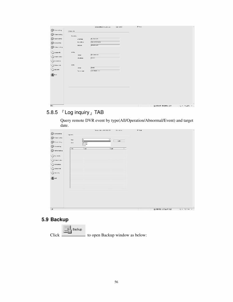
5.8.4 『Network info.』TAB
Basic network info.: Current IP address , MAC address and gateway IP address.
Dial up: If DVR use PPPoE Dial up connection then it will show “Action” and
display current IP address that assigned by network service provider.
DDNS:
If DVR enable DDNS client then if will display “Action” and display
current domain name.
56
5.8.5 『Log inquiry』TAB
Query remote DVR event by type(All/Operation/Abnormal/Event) and target
date.
5.9 Backup
Click to open Backup window as below:
57
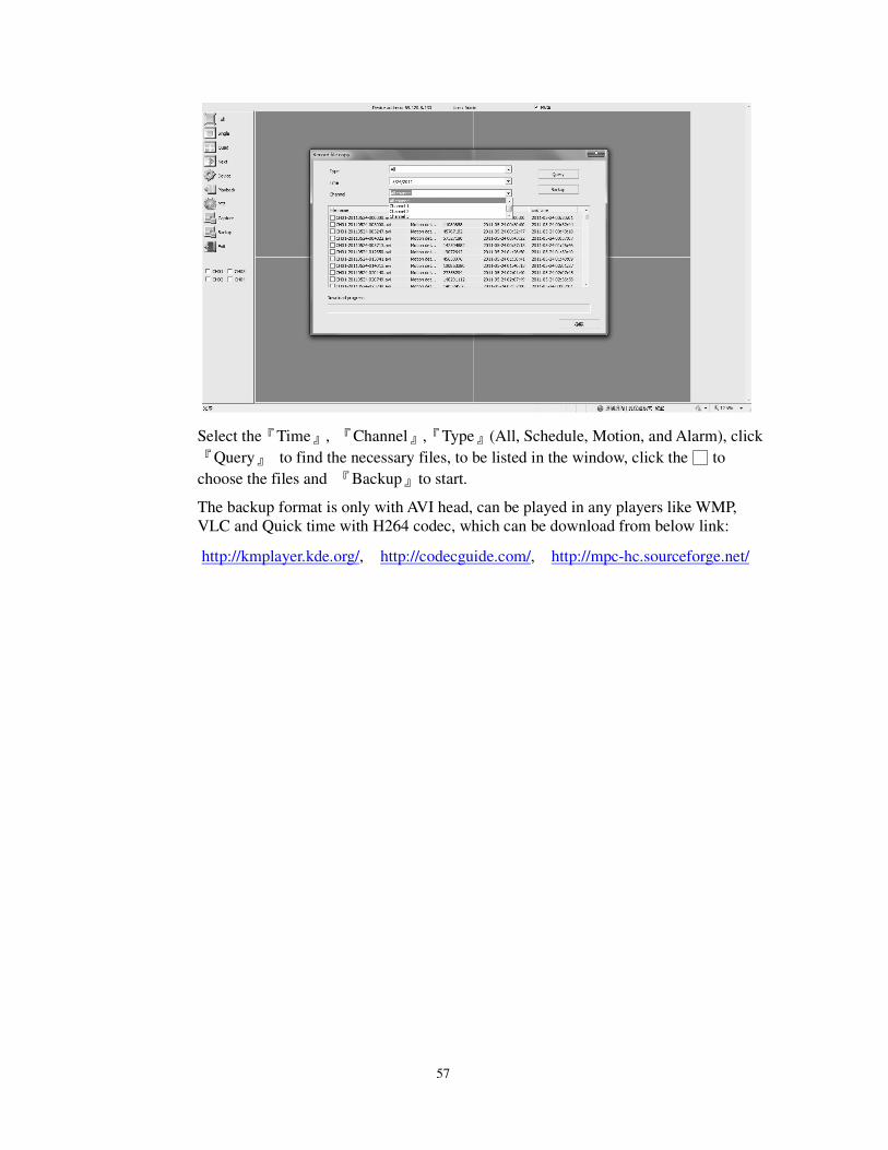
Select the『Time』, 『Channel』,『Type』(All, Schedule, Motion, and Alarm), click
『Query』 to find the necessary files, to be listed in the window, click the to
choose the files and 『Backup』to start.
The backup format is only with AVI head, can be played in any players like WMP,
VLC and Quick time with H264 codec, which can be download from below link:
http://kmplayer.kde.org/, http://codecguide.com/, http://mpc-hc.sourceforge.net/
58
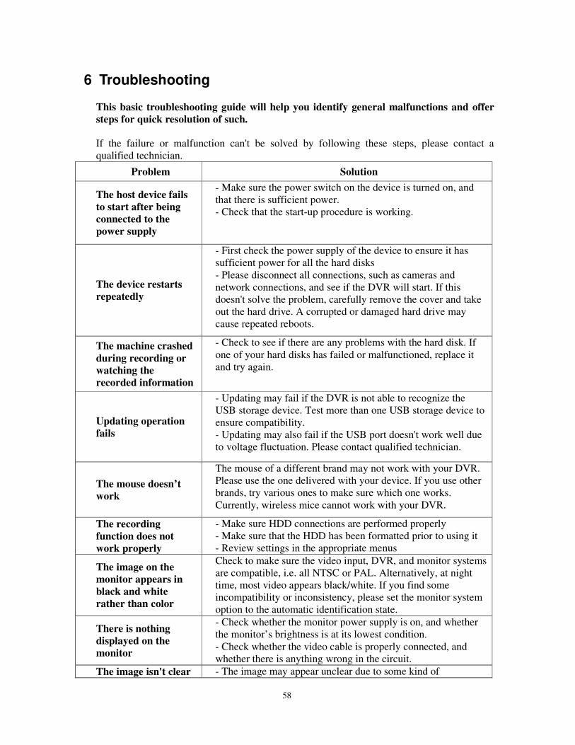
6 Troubleshooting
This basic troubleshooting guide will help you identify general malfunctions and offer
steps for quick resolution of such.
If the failure or malfunction can't be solved by following these steps, please contact a
qualified technician.
Problem Solution
The host device fails
to start after being
connected to the
power supply
- Make sure the power switch on the device is turned on, and
that there is sufficient power.
- Check that the start-up procedure is working.
The device restarts
repeatedly
- First check the power supply of the device to ensure it has
sufficient power for all the hard disks
- Please disconnect all connections, such as cameras and
network connections, and see if the DVR will start. If this
doesn't solve the problem, carefully remove the cover and take
out the hard drive. A corrupted or damaged hard drive may
cause repeated reboots.
The machine crashed
during recording or
watching the
recorded information
- Check to see if there are any problems with the hard disk. If
one of your hard disks has failed or malfunctioned, replace it
and try again.
Updating operation
fails
- Updating may fail if the DVR is not able to recognize the
USB storage device. Test more than one USB storage device to
ensure compatibility.
- Updating may also fail if the USB port doesn't work well due
to voltage fluctuation. Please contact qualified technician.
The mouse doesn’t
work
The mouse of a different brand may not work with your DVR.
Please use the one delivered with your device. If you use other
brands, try various ones to make sure which one works.
Currently, wireless mice cannot work with your DVR.
The recording
function does not
work properly
- Make sure HDD connections are performed properly
- Make sure that the HDD has been formatted prior to using it
- Review settings in the appropriate menus
The image on the
monitor appears in
black and white
rather than color
Check to make sure the video input, DVR, and monitor systems
are compatible, i.e. all NTSC or PAL. Alternatively, at night
time, most video appears black/white. If you find some
incompatibility or inconsistency, please set the monitor system
option to the automatic identification state.
There is nothing
displayed on the
monitor
- Check whether the monitor power supply is on, and whether
the monitor’s brightness is at its lowest condition.
- Check whether the video cable is properly connected, and
whether there is anything wrong in the circuit.
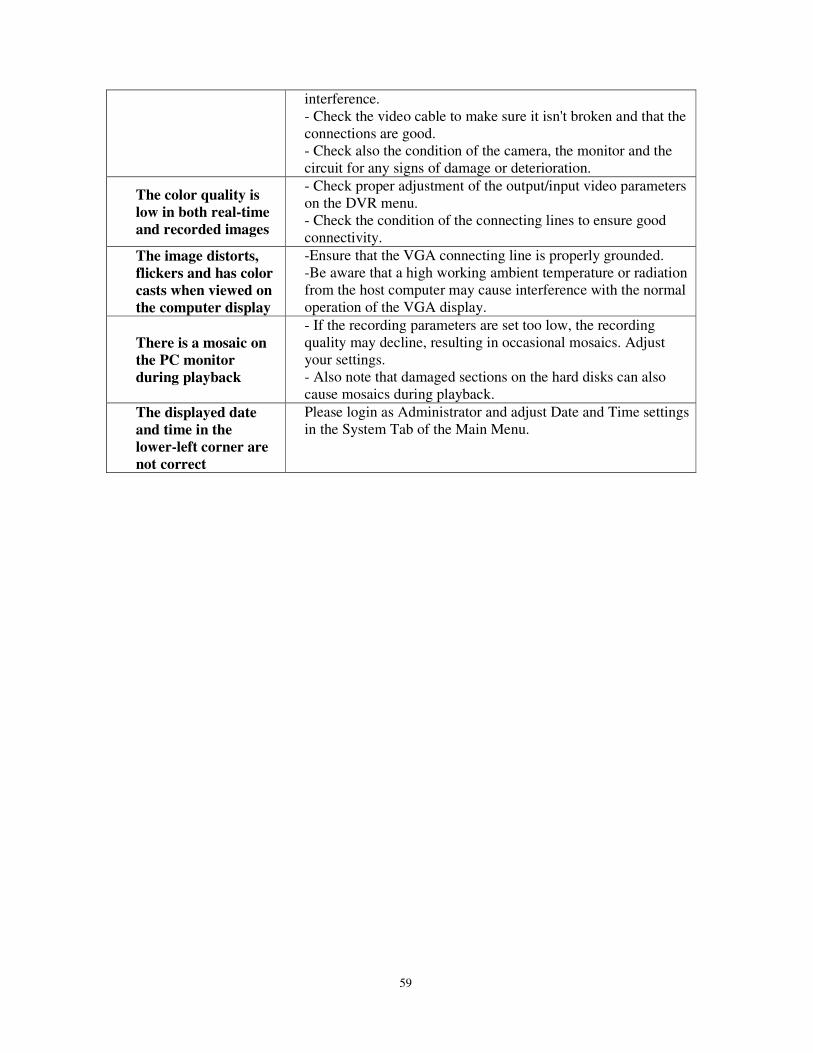
The image isn't clear - The image may appear unclear due to some kind of
59
interference.
- Check the video cable to make sure it isn't broken and that the
connections are good.
- Check also the condition of the camera, the monitor and the
circuit for any signs of damage or deterioration.
The color quality is
low in both real-time
and recorded images
- Check proper adjustment of the output/input video parameters
on the DVR menu.
- Check the condition of the connecting lines to ensure good
connectivity.
The image distorts,
flickers and has color
casts when viewed on
the computer display
-Ensure that the VGA connecting line is properly grounded.
-Be aware that a high working ambient temperature or radiation
from the host computer may cause interference with the normal
operation of the VGA display.
There is a mosaic on
the PC monitor
during playback
- If the recording parameters are set too low, the recording
quality may decline, resulting in occasional mosaics. Adjust
your settings.
- Also note that damaged sections on the hard disks can also
cause mosaics during playback.
The displayed date
and time in the
lower-left corner are
not correct
Please login as Administrator and adjust Date and Time settings
in the System Tab of the Main Menu.
60
7 Appendix
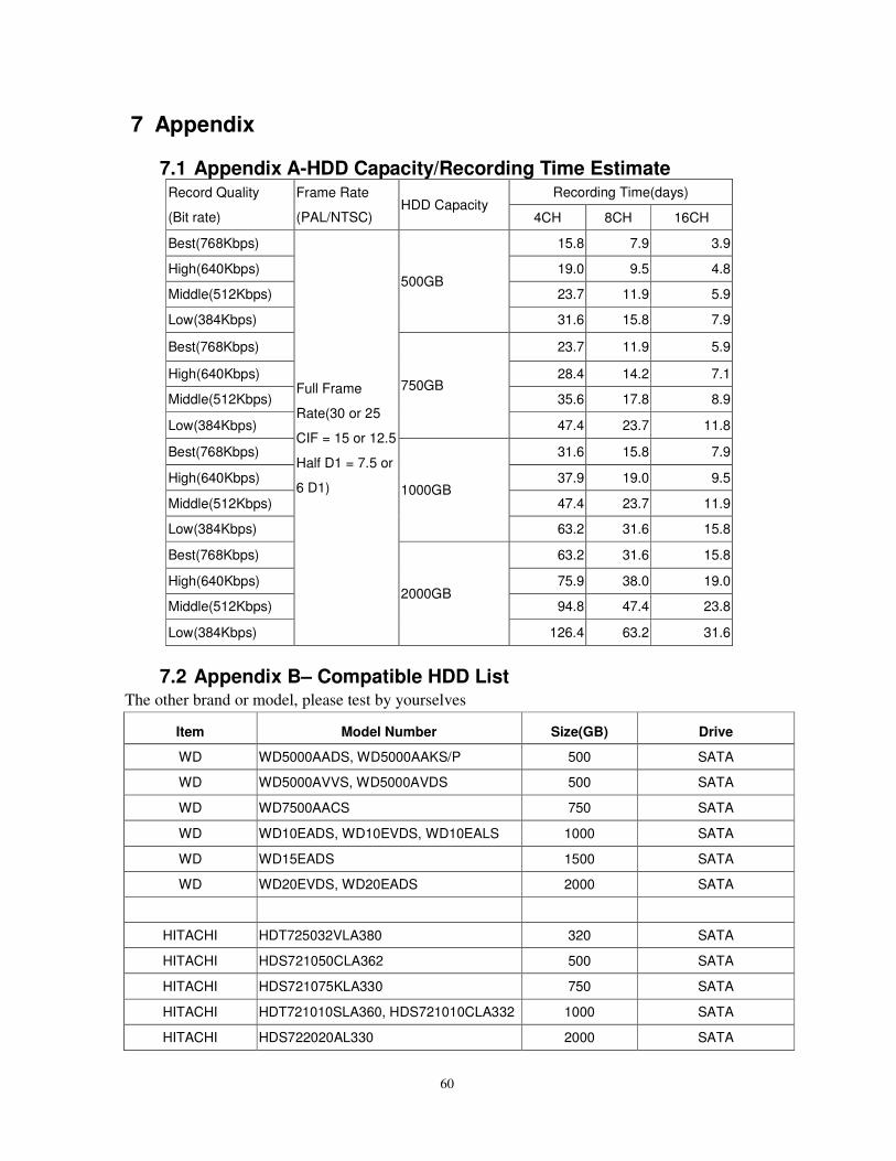
7.1 Appendix A-HDD Capacity/Recording Time Estimate Record Quality
(Bit rate)
Frame Rate
(PAL/NTSC) HDD Capacity
Recording Time(days)
4CH 8CH 16CH
Best(768Kbps)
Full Frame
Rate(30 or 25
CIF = 15 or 12.5
Half D1 = 7.5 or
6 D1)
500GB
15.8 7.9 3.9
High(640Kbps) 19.0 9.5 4.8
Middle(512Kbps) 23.7 11.9 5.9
Low(384Kbps) 31.6 15.8 7.9
Best(768Kbps)
750GB
23.7 11.9 5.9
High(640Kbps) 28.4 14.2 7.1
Middle(512Kbps) 35.6 17.8 8.9
Low(384Kbps) 47.4 23.7 11.8
Best(768Kbps)
1000GB
31.6 15.8 7.9
High(640Kbps) 37.9 19.0 9.5
Middle(512Kbps) 47.4 23.7 11.9
Low(384Kbps) 63.2 31.6 15.8
Best(768Kbps)
2000GB
63.2 31.6 15.8
High(640Kbps) 75.9 38.0 19.0
Middle(512Kbps) 94.8 47.4 23.8
Low(384Kbps) 126.4 63.2 31.6
7.2 Appendix B– Compatible HDD List The other brand or model, please test by yourselves
Item Model Number Size(GB) Drive
WD WD5000AADS, WD5000AAKS/P 500 SATA
WD WD5000AVVS, WD5000AVDS 500 SATA
WD WD7500AACS 750 SATA
WD WD10EADS, WD10EVDS, WD10EALS 1000 SATA
WD WD15EADS 1500 SATA
WD WD20EVDS, WD20EADS 2000 SATA
HITACHI HDT725032VLA380 320 SATA
HITACHI HDS721050CLA362 500 SATA
HITACHI HDS721075KLA330 750 SATA
HITACHI HDT721010SLA360, HDS721010CLA332 1000 SATA
HITACHI HDS722020AL330 2000 SATA
61
Seagate ST3250310SV 250 SATA
Seagate
ST3500320SV, ST3500320AS,
ST3500418AS 500 SATA
Seagate ST31000528AS, ST31000520AS 1000 SATA
Seagate ST31500341AS 1500 SATA
Seagate ST32000542AS, ST32000641AS 2000 SATA
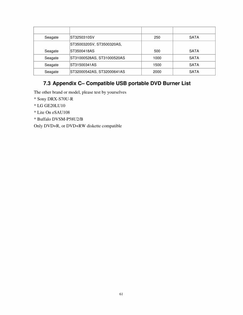
7.3 Appendix C– Compatible USB portable DVD Burner List
The other brand or model, please test by yourselves * Sony DRX-S70U-R
* LG GE20LU10
* Lite On eSAU108
* Buffalo DVSM-P58U2/B
Only DVD+R, or DVD+RW diskette compatible


![Security System Supplier in Malaysia | Saxco - INTERCOM · 2018. 1. 4. · INTERCOM [ KIC-301/304/308 (1CH/4CH/8CH) / 300S (SUB) ]-Delightful signal sound.-LED Indicator for call](https://img.pdfslide.us/doc/110x75/60ca0a109384a906294de9af/security-system-supplier-in-malaysia-saxco-intercom-2018-1-4-intercom-.jpg)