Embed Size (px)
DESCRIPTION
Datasheet
Citation preview
Page 1 of 2
IACS® 4CH 3A Mini Switching Board
(CMOS / TTL / Logic Level Switch Board, Four Channel) Information / Instructions / Datasheet
Last Updated: August 2012
Versions & Variations
70 x 50 x < 164Automotive /
Factory Automation
General (NO /
COM / NC)
Rarely Available4CH-3A-48V48V DC (+/- 12%)
70 x 50 x < 164Multipurpose /
Automotive / Robot
General (NO /
COM / NC)
Usually Available4CH-3A-24V24V DC (+/- 15%)
70 x 50 x < 164Automotive /
Factory Automation
General (NO /
COM / NC)
Rarely Available4CH-3A-36V36V DC (+/- 15%)
70 x 50 x < 164May be powered by
a 9V battery
General (NO /
COM / NC)
Short Lead Time4CH-3A-9V9V DC (+/- 20%)
70 x 50 x < 164Multipurpose /
Automotive / Robot
General (NO /
COM / NC)
Usually Available4CH-3A-12V12V DC (+/- 20%)
Multipurpose /
Security / Control
Good if you need to
run off batteries
Common Usage
70 x 50 x < 164General (NO /
COM / NC)
Usually Available4CH-3A-5V5V DC (+/- 20%)
4
Channels
General (NO /
COM / NC)
Intended Use
70 x 50 x < 16Short Lead Time4CH-3A-3V3V DC (+/- 20%)
Dimensions (mm)AvailabilityPart NumberSupply Voltage
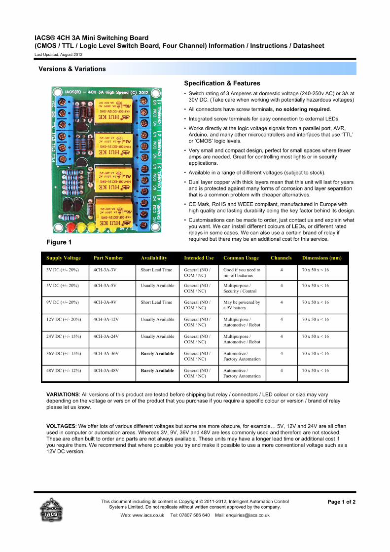
Specification & Features
• Switch rating of 3 Amperes at domestic voltage (240-250v AC) or 3A at
30V DC. (Take care when working with potentially hazardous voltages)
• All connectors have screw terminals, no soldering required.
• Integrated screw terminals for easy connection to external LEDs.
• Works directly at the logic voltage signals from a parallel port, AVR,
Arduino, and many other microcontrollers and interfaces that use ‘TTL’
or ‘CMOS’ logic levels.
• Very small and compact design, perfect for small spaces where fewer
amps are needed. Great for controlling most lights or in security
applications.
• Available in a range of different voltages (subject to stock).
• Dual layer copper with thick layers mean that this unit will last for years
and is protected against many forms of corrosion and layer separation
that is a common problem with cheaper alternatives.
• CE Mark, RoHS and WEEE compliant, manufactured in Europe with
high quality and lasting durability being the key factor behind its design.
• Customisations can be made to order, just contact us and explain what
you want. We can install different colours of LEDs, or different rated
relays in some cases. We can also use a certain brand of relay if
required but there may be an additional cost for this service.
VARIATIONS: All versions of this product are tested before shipping but relay / connectors / LED colour or size may vary
depending on the voltage or version of the product that you purchase if you require a specific colour or version / brand of relay
please let us know.
VOLTAGES: We offer lots of various different voltages but some are more obscure, for example… 5V, 12V and 24V are all often
used in computer or automation areas. Whereas 3V, 9V, 36V and 48V are less commonly used and therefore are not stocked.
These are often built to order and parts are not always available. These units may have a longer lead time or additional cost if
you require them. We recommend that where possible you try and make it possible to use a more conventional voltage such as a
12V DC version.
This document including its content is Copyright © 2011-2012, Intelligent Automation Control
Systems Limited. Do not replicate without written consent approved by the company.
Web: www.iacs.co.uk Tel: 07807 566 640 Mail: [email protected]
Figure 1Figure 1
Page 2 of 2This document including its content is Copyright © 2011-2012, Intelligent Automation Control
Systems Limited. Do not replicate without written consent approved by the company.
Web: www.iacs.co.uk Tel: 07807 566 640 Mail: [email protected]
IACS® 4CH 3A Mini Switching Board
(CMOS / TTL / Logic Level Switch Board, Four Channel) Information / Instructions / Datasheet
Last Updated: August 2012
Connection Guide / Instructions
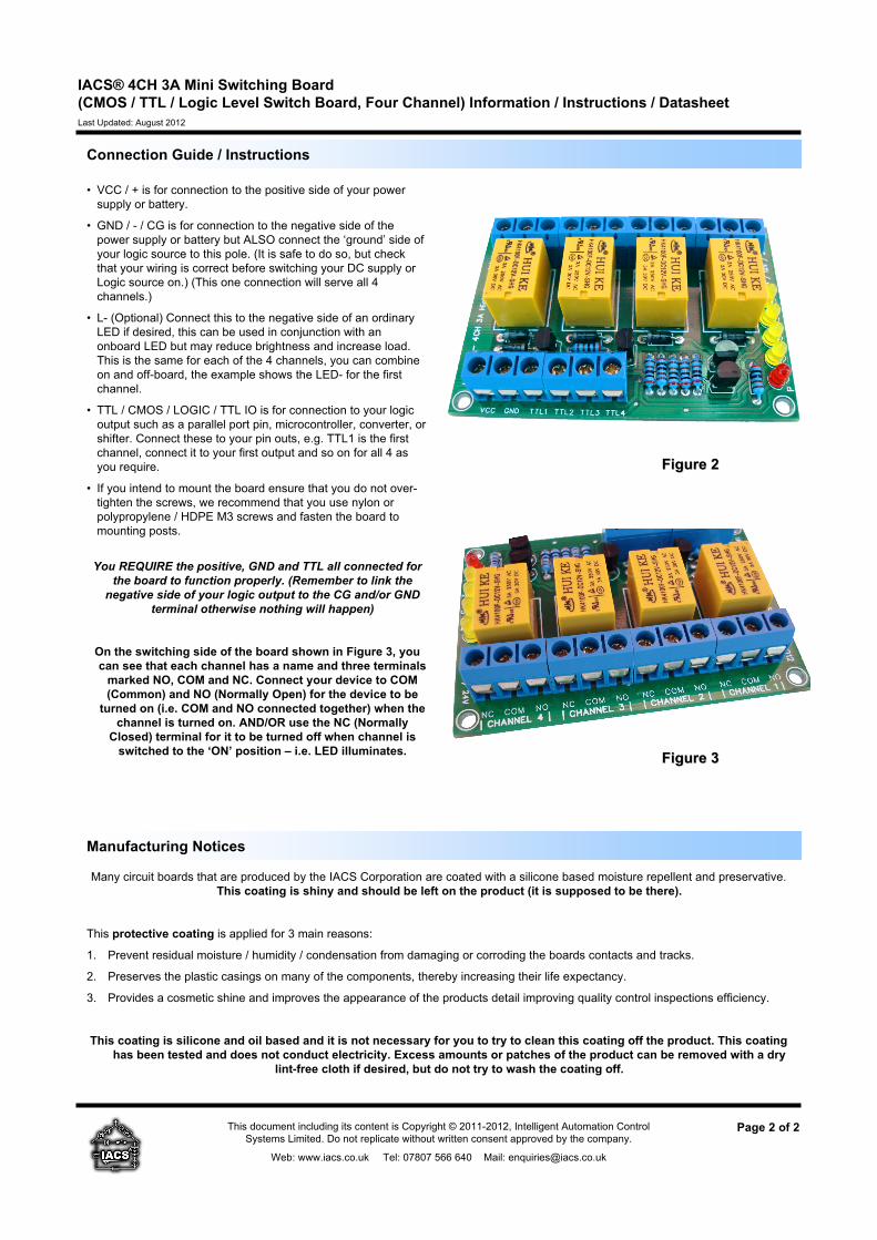
Figure 2Figure 2
Manufacturing Notices
Many circuit boards that are produced by the IACS Corporation are coated with a silicone based moisture repellent and preservative.
This coating is shiny and should be left on the product (it is supposed to be there).
This protective coating is applied for 3 main reasons:
1. Prevent residual moisture / humidity / condensation from damaging or corroding the boards contacts and tracks.
2. Preserves the plastic casings on many of the components, thereby increasing their life expectancy.
3. Provides a cosmetic shine and improves the appearance of the products detail improving quality control inspections efficiency.
This coating is silicone and oil based and it is not necessary for you to try to clean this coating off the product. This coating
has been tested and does not conduct electricity. Excess amounts or patches of the product can be removed with a dry
lint-free cloth if desired, but do not try to wash the coating off.
• VCC / + is for connection to the positive side of your power
supply or battery.
• GND / - / CG is for connection to the negative side of the
power supply or battery but ALSO connect the ‘ground’ side of
your logic source to this pole. (It is safe to do so, but check
that your wiring is correct before switching your DC supply or
Logic source on.) (This one connection will serve all 4
channels.)
• L- (Optional) Connect this to the negative side of an ordinary
LED if desired, this can be used in conjunction with an
onboard LED but may reduce brightness and increase load.
This is the same for each of the 4 channels, you can combine
on and off-board, the example shows the LED- for the first
channel.
• TTL / CMOS / LOGIC / TTL IO is for connection to your logic
output such as a parallel port pin, microcontroller, converter, or
shifter. Connect these to your pin outs, e.g. TTL1 is the first
channel, connect it to your first output and so on for all 4 as
you require.
• If you intend to mount the board ensure that you do not over-
tighten the screws, we recommend that you use nylon or
polypropylene / HDPE M3 screws and fasten the board to
mounting posts.
You REQUIRE the positive, GND and TTL all connected for
the board to function properly. (Remember to link the
negative side of your logic output to the CG and/or GND
terminal otherwise nothing will happen)
On the switching side of the board shown in Figure 3, you
can see that each channel has a name and three terminals
marked NO, COM and NC. Connect your device to COM
(Common) and NO (Normally Open) for the device to be
turned on (i.e. COM and NO connected together) when the
channel is turned on. AND/OR use the NC (Normally
Closed) terminal for it to be turned off when channel is
switched to the ‘ON’ position – i.e. LED illuminates.Figure 3Figure 3