Embed Size (px)
Citation preview

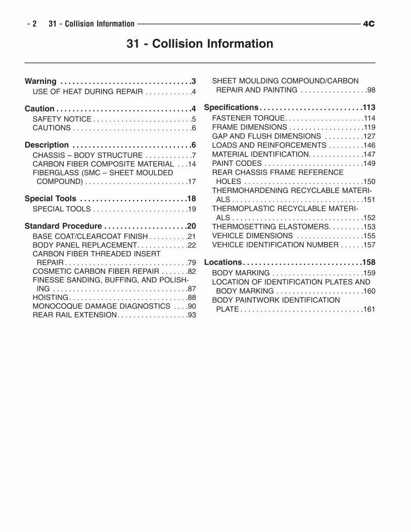
31 - COLLISION INFORMATION . . . . . . . . . . . .2
4C - 1
31 - Collision Information
Warning . . . . . . . . . . . . . . . . . . . . . . . . . . . . . . . . .3
USE OF HEAT DURING REPAIR . . . . . . . . . . . .4
Caution . . . . . . . . . . . . . . . . . . . . . . . . . . . . . . . . . .4
SAFETY NOTICE . . . . . . . . . . . . . . . . . . . . . . . . .5CAUTIONS . . . . . . . . . . . . . . . . . . . . . . . . . . . . . .6
Description . . . . . . . . . . . . . . . . . . . . . . . . . . . . . .6
CHASSIS – BODY STRUCTURE . . . . . . . . . . . .7CARBON FIBER COMPOSITE MATERIAL . . .14FIBERGLASS (SMC – SHEET MOULDEDCOMPOUND) . . . . . . . . . . . . . . . . . . . . . . . . . .17
Special Tools . . . . . . . . . . . . . . . . . . . . . . . . . . .18
SPECIAL TOOLS . . . . . . . . . . . . . . . . . . . . . . . .19
Standard Procedure . . . . . . . . . . . . . . . . . . . . .20
BASE COAT/CLEARCOAT FINISH . . . . . . . . . .21BODY PANEL REPLACEMENT. . . . . . . . . . . . .22CARBON FIBER THREADED INSERTREPAIR . . . . . . . . . . . . . . . . . . . . . . . . . . . . . . .79
COSMETIC CARBON FIBER REPAIR . . . . . . .82FINESSE SANDING, BUFFING, AND POLISH-ING . . . . . . . . . . . . . . . . . . . . . . . . . . . . . . . . . .87
HOISTING. . . . . . . . . . . . . . . . . . . . . . . . . . . . . .88MONOCOQUE DAMAGE DIAGNOSTICS . . . .90REAR RAIL EXTENSION. . . . . . . . . . . . . . . . . .93
SHEET MOULDING COMPOUND/CARBON
REPAIR AND PAINTING . . . . . . . . . . . . . . . . .98
Specifications. . . . . . . . . . . . . . . . . . . . . . . . . .113
FASTENER TORQUE. . . . . . . . . . . . . . . . . . . .114
FRAME DIMENSIONS . . . . . . . . . . . . . . . . . . .119
GAP AND FLUSH DIMENSIONS . . . . . . . . . .127
LOADS AND REINFORCEMENTS . . . . . . . . .146
MATERIAL IDENTIFICATION. . . . . . . . . . . . . .147
PAINT CODES . . . . . . . . . . . . . . . . . . . . . . . . .149
REAR CHASSIS FRAME REFERENCE
HOLES . . . . . . . . . . . . . . . . . . . . . . . . . . . . . .150
THERMOHARDENING RECYCLABLE MATERI-
ALS . . . . . . . . . . . . . . . . . . . . . . . . . . . . . . . . .151
THERMOPLASTIC RECYCLABLE MATERI-
ALS . . . . . . . . . . . . . . . . . . . . . . . . . . . . . . . . .152
THERMOSETTING ELASTOMERS. . . . . . . . .153
VEHICLE DIMENSIONS . . . . . . . . . . . . . . . . .155
VEHICLE IDENTIFICATION NUMBER . . . . . .157
Locations. . . . . . . . . . . . . . . . . . . . . . . . . . . . . .158
BODY MARKING . . . . . . . . . . . . . . . . . . . . . . .159
LOCATION OF IDENTIFICATION PLATES AND
BODY MARKING . . . . . . . . . . . . . . . . . . . . . .160
BODY PAINTWORK IDENTIFICATION
PLATE . . . . . . . . . . . . . . . . . . . . . . . . . . . . . . .161
- 2 31 - Collision Information 4C

Warning
4C 31 - Collision Information 31 - 3
USE OF HEAT DURING REPAIR
WARNING: Chrysler Group LLC engineering’s position on the use of heat during collision repair is as
follows:
• Any body panel or frame component damaged which is to be repaired and reused, must be
repaired using the “cold straightening” method. No heat may be used during the straightening
process.
• During rough straightening prior to panel replacement, damaged panels or frame components may
be heated to assist in body/frame realignment. The application of heat must be constrained to the
parts which will be replaced and not allowed to affect any other components.
This “no heat” recommendation is due to the extensive use of high strength and advanced high strength
steels in Chrysler Group LLC products. High-strength materials can be substantially and negatively affected
from heat input which will not be obviously known to the repairer or consumer.
Ignoring these recommendations may lead to serious compromises in the ability to protect occupants in a
future collision event, reduce the engineered qualities and attributes, or decrease the durability and
reliability of the vehicle.
This statement supersedes any previously released information by the Chrysler Group LLC.
Failure to follow these instructions may result in serious or fatal injury.
Caution
31 - 4 31 - Collision Information 4C
SAFETY NOTICE
CAUTION: All service and rebuilding instructions contained herein are applicable to, and for the
convenience of, the automotive trade only. All test and repair procedures on components or
assemblies in non-automotive applications should be repaired in accordance with instructions
supplied by the manufacturer of the total product.
Proper service and repair is important to the safe, reliable operation of all motor vehicles. The
service produces recommended and described in this publication were developed for
professional service personnel, and are effective methods for performing vehicle repair.
Following these procedures will help ensure efficient economical vehicle performance and
service reliability. Some service procedures require the use of special tools designed for
specific procedures. These special tools should be used as recommended throughout this
publication.
Special attention should be exercised when working with spring-or tension-loaded fasteners
and devices such as E-Clips, Circlips, Snap rings, etc., since careless removal may cause
personal injury. Always wear safety goggles when working on vehicles or vehicle components.
It is important to note that this publication contains various Cautions and Warnings. These
should be read carefully in order to minimize risk of personal injury or the possibility that
improper service methods may damage the vehicle or render it unsafe. It is important to note
that these Cautions and Warnings cover only the situations and procedures Chrysler Group
LLC has encountered and recommended. Chrysler Group LLC cannot possibly know, evaluate,
and advise the service trade of all conceivable ways in which service may be performed, or
of the possible hazards of each. Consequently, Chrysler Group LLC has not undertaken
any such broad service review. Accordingly, anyone uses a service procedure or tool that is not
recommended in this publication must be certain that neither personal safety, nor vehicle
safety, will be jeopardized by the service methods they select.
4C 31 - Collision Information 31 - 5
CAUTIONS
CAUTION: Work carefully on the trim details and use the recommended tools correctly to prevent damage.
CAUTION: Before working on the electrical system (connectors, electrical components, wiring, etc.) turn
the ignition key to STOP and disconnect the battery.
CAUTION: The battery terminals must only be disconnected with the ignition key at STOP or extracted,
never with the key at MAR (Accessory/On/Run) or with engine started. The battery terminals
must only be disconnected at least 1 minute after turning the ignition key to STOP and having
closed the driver side door to prevent the hydraulic system pressurization stage, which starts
when the door is opened, from being interrupted before its completion.
CAUTION: When reconnecting the cables, also make sure the driver’s door is closed.
CAUTION: All mounting screws for components (structural and nonstructural) mounted to the carbon
chassis, outside the car, are made of stainless steel. The use of mounting elements in other
materials may induce “galvanic” corrosion. Therefore, when installing, take particular care to
reuse (or replace if applicable) mounting elements with the characteristics described above.
Description
31 - 6 31 - Collision Information 4C
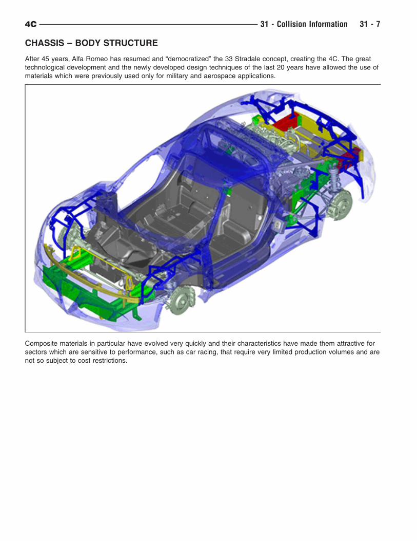
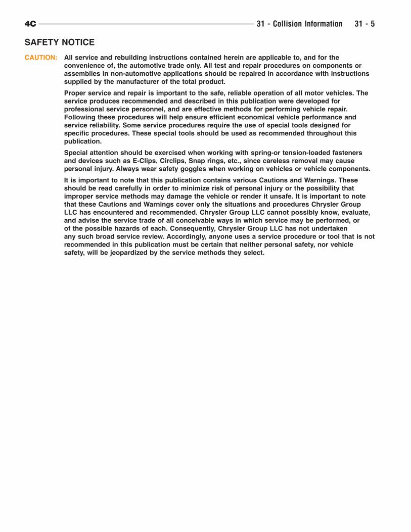
CHASSIS – BODY STRUCTURE
After 45 years, Alfa Romeo has resumed and “democratized” the 33 Stradale concept, creating the 4C. The great
technological development and the newly developed design techniques of the last 20 years have allowed the use of
materials which were previously used only for military and aerospace applications.
Composite materials in particular have evolved very quickly and their characteristics have made them attractive for
sectors which are sensitive to performance, such as car racing, that require very limited production volumes and are
not so subject to cost restrictions.
4C 31 - Collision Information 31 - 7
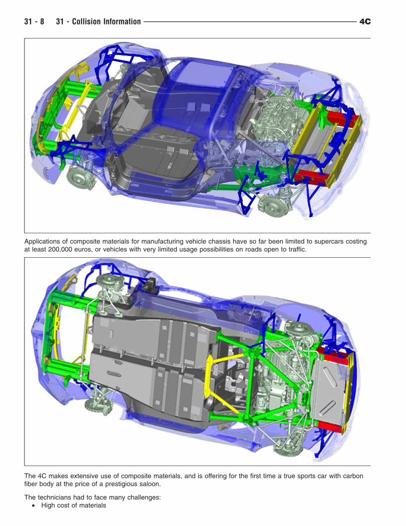
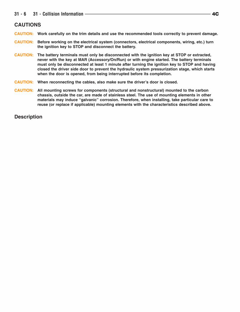
Applications of composite materials for manufacturing vehicle chassis have so far been limited to supercars costing
at least 200,000 euros, or vehicles with very limited usage possibilities on roads open to traffic.
The 4C makes extensive use of composite materials, and is offering for the first time a true sports car with carbon
fiber body at the price of a prestigious saloon.
The technicians had to face many challenges:
• High cost of materials
31 - 8 31 - Collision Information 4C
• Difficulty mass production application
• High design complexity
All this contributes to obtaining two main advantages: a high level of integration between components (a single
complex carbon part instead of many welded or bolted steel parts) and a considerable reduction of weight.
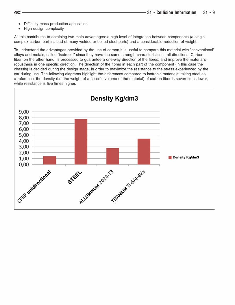
To understand the advantages provided by the use of carbon it is useful to compare this material with "conventional"
alloys and metals, called "isotropic" since they have the same strength characteristics in all directions. Carbon
fiber, on the other hand, is processed to guarantee a one-way direction of the fibres, and improve the material’s
robustness in one specific direction. The direction of the fibres in each part of the component (in this case the
chassis) is decided during the design stage, in order to maximize the resistance to the stress experienced by the
car during use. The following diagrams highlight the differences compared to isotropic materials: taking steel as
a reference, the density (i.e. the weight of a specific volume of the material) of carbon fiber is seven times lower,
while resistance is five times higher.
4C 31 - Collision Information 31 - 9
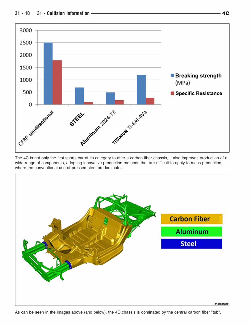
The 4C is not only the first sports car of its category to offer a carbon fiber chassis, it also improves production of a
wide range of components, adopting innovative production methods that are difficult to apply to mass production,
where the conventional use of pressed steel predominates.
As can be seen in the images above (and below), the 4C chassis is dominated by the central carbon fiber "tub",
31 - 10 31 - Collision Information 4C
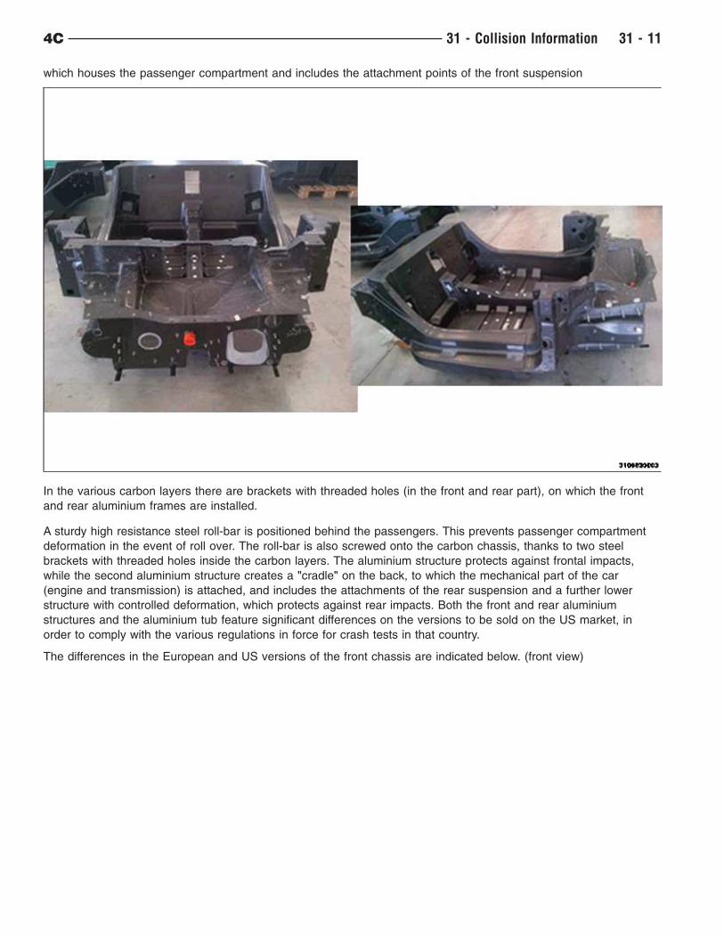
which houses the passenger compartment and includes the attachment points of the front suspension
In the various carbon layers there are brackets with threaded holes (in the front and rear part), on which the front
and rear aluminium frames are installed.
A sturdy high resistance steel roll-bar is positioned behind the passengers. This prevents passenger compartment
deformation in the event of roll over. The roll-bar is also screwed onto the carbon chassis, thanks to two steel
brackets with threaded holes inside the carbon layers. The aluminium structure protects against frontal impacts,
while the second aluminium structure creates a "cradle" on the back, to which the mechanical part of the car
(engine and transmission) is attached, and includes the attachments of the rear suspension and a further lower
structure with controlled deformation, which protects against rear impacts. Both the front and rear aluminium
structures and the aluminium tub feature significant differences on the versions to be sold on the US market, in
order to comply with the various regulations in force for crash tests in that country.
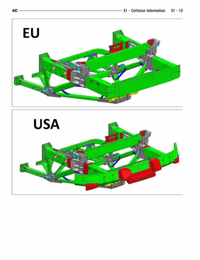
The differences in the European and US versions of the front chassis are indicated below. (front view)
4C 31 - Collision Information 31 - 11
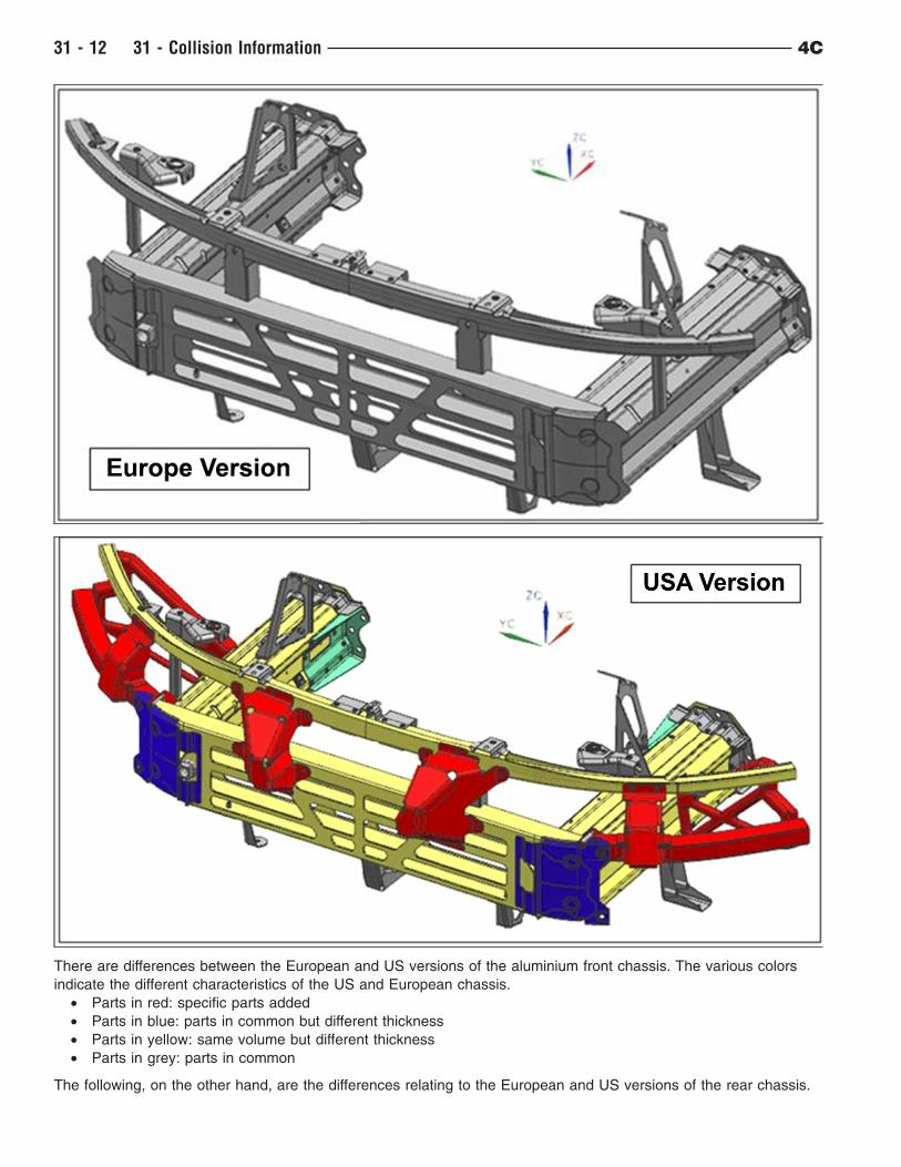
There are differences between the European and US versions of the aluminium front chassis. The various colors
indicate the different characteristics of the US and European chassis.
• Parts in red: specific parts added
• Parts in blue: parts in common but different thickness
• Parts in yellow: same volume but different thickness
• Parts in grey: parts in common
The following, on the other hand, are the differences relating to the European and US versions of the rear chassis.
31 - 12 31 - Collision Information 4C
4C 31 - Collision Information 31 - 13
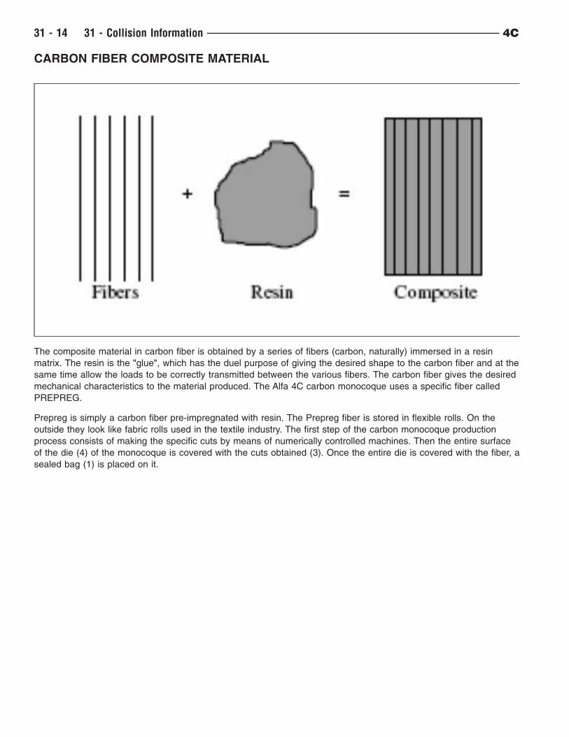
CARBON FIBER COMPOSITE MATERIAL
The composite material in carbon fiber is obtained by a series of fibers (carbon, naturally) immersed in a resin
matrix. The resin is the "glue", which has the duel purpose of giving the desired shape to the carbon fiber and at the
same time allow the loads to be correctly transmitted between the various fibers. The carbon fiber gives the desired
mechanical characteristics to the material produced. The Alfa 4C carbon monocoque uses a specific fiber called
PREPREG.
Prepreg is simply a carbon fiber pre-impregnated with resin. The Prepreg fiber is stored in flexible rolls. On the
outside they look like fabric rolls used in the textile industry. The first step of the carbon monocoque production
process consists of making the specific cuts by means of numerically controlled machines. Then the entire surface
of the die (4) of the monocoque is covered with the cuts obtained (3). Once the entire die is covered with the fiber, a
sealed bag (1) is placed on it.
31 - 14 31 - Collision Information 4C
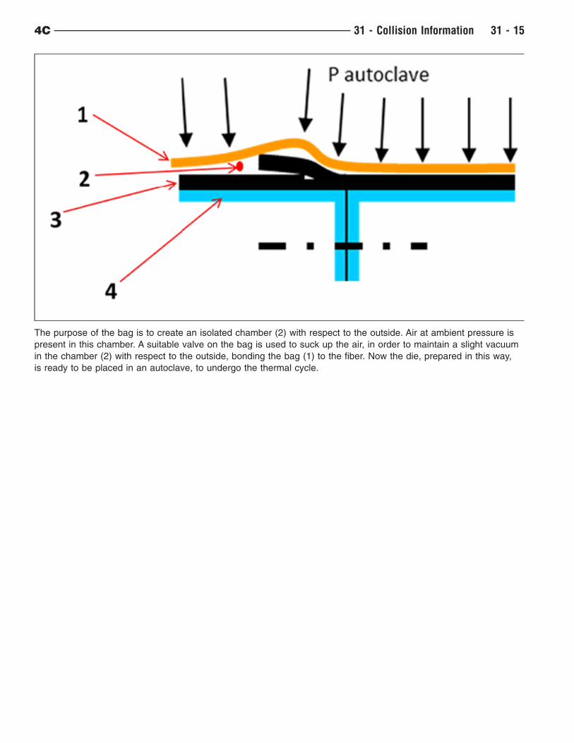
The purpose of the bag is to create an isolated chamber (2) with respect to the outside. Air at ambient pressure is
present in this chamber. A suitable valve on the bag is used to suck up the air, in order to maintain a slight vacuum
in the chamber (2) with respect to the outside, bonding the bag (1) to the fiber. Now the die, prepared in this way,
is ready to be placed in an autoclave, to undergo the thermal cycle.
4C 31 - Collision Information 31 - 15
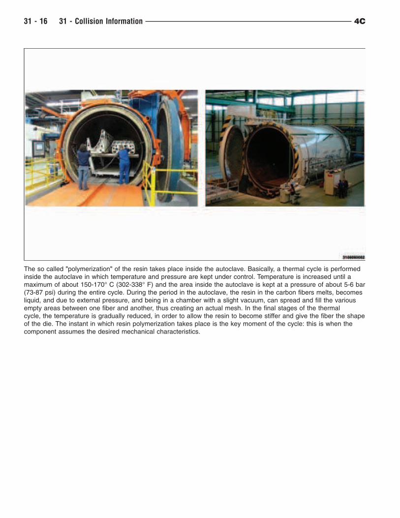
The so called "polymerization" of the resin takes place inside the autoclave. Basically, a thermal cycle is performed
inside the autoclave in which temperature and pressure are kept under control. Temperature is increased until a
maximum of about 150-170° C (302-338° F) and the area inside the autoclave is kept at a pressure of about 5-6 bar
(73-87 psi) during the entire cycle. During the period in the autoclave, the resin in the carbon fibers melts, becomes
liquid, and due to external pressure, and being in a chamber with a slight vacuum, can spread and fill the various
empty areas between one fiber and another, thus creating an actual mesh. In the final stages of the thermal
cycle, the temperature is gradually reduced, in order to allow the resin to become stiffer and give the fiber the shape
of the die. The instant in which resin polymerization takes place is the key moment of the cycle: this is when the
component assumes the desired mechanical characteristics.
31 - 16 31 - Collision Information 4C
FIBERGLASS (SMC – SHEET MOULDED COMPOUND)
SMC (sheet moulding compound), commonly defined fiberglass, is a thermosetting material made of fiberglass
sheets, minerals, pigments and unsaturated polyester resins, recently widespread thanks to its excellent chemical-
physical and mechanical characteristics. The production technology consists of hot-shaping in coupled (male-
female) steel dies. SMC is pressed at a temperature of about 150° C (302° F) and a pressure of 50-120 kg/cm2
(711-1706 psi). Hot-polymerization allows a perfectly homogeneous product to be obtained at the end of the
treatment.
A particular property of SMC is the possibility of changing its components as necessary, in order to obtain specific
characteristics according to the application requirements. In particular, by changing orientation and the type of
fiberglass it is possible to obtain significant differences in the chemical-physical characteristics of the finished
product, and therefore to improve the performance required according to the various applications.
The main advantages obtained by using this material are:
• significant weight/performance ratio with respect to other materials
• high thermal and mechanical resistance
• high dielectric rigidity
• low specific weight
• optimal dimensional stability
• excellent resistance to corrosion of chemicals and atmospheric agents
In addition, the finished product has the following characteristics:
• homogeneous and smooth surface
• pleasant design
• low weight and easy transport
• easy assembly and processing
• low installing cost
• high safety for personnel during handling of parts
• unlimited life and absolute lack of maintenance.
4C 31 - Collision Information 31 - 17
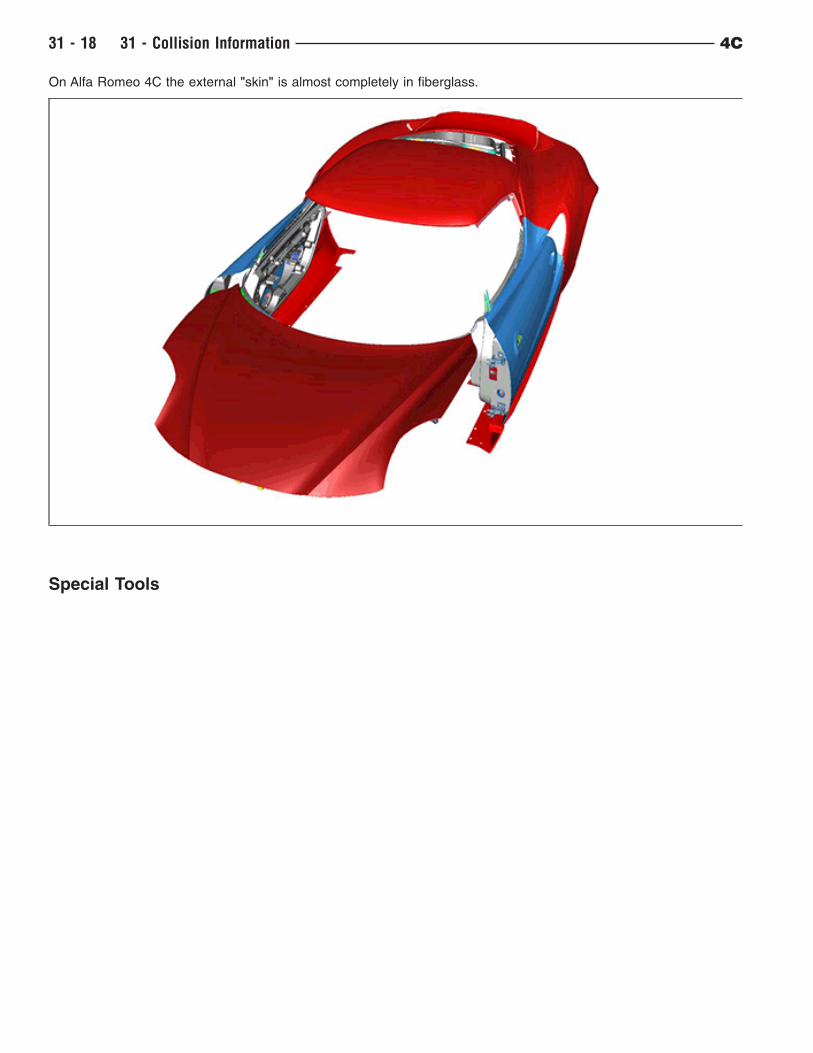
On Alfa Romeo 4C the external "skin" is almost completely in fiberglass.
Special Tools
31 - 18 31 - Collision Information 4C

SPECIAL TOOLS
Tool Name Function
2014100000 Right lifting trolley Vehicle positioning on a lift
2014101000 Left lifting trolley Vehicle positioning on a lift
4C 31 - Collision Information 31 - 19

Standard Procedure
31 - 20 31 - Collision Information 4C

BASE COAT/CLEARCOAT FINISH
The original equipment paint finish is a multi step process that involves cleaning, applying electro de-position
(E-coat), anti-chip primer, basecoat, and clearcoat steps.
CAUTION: Do not use abrasive chemicals, abrasive compounds or harsh alkaline based cleaning solvents
on the painted surfaces of a vehicle. Failure to follow this caution can result in damage to
vehicle finish.
On most vehicles a two-part paint application (basecoat/clearcoat) is used. Color paint that is applied to primer is
called basecoat. A clear coat paint is then applied to protect the basecoat from ultraviolet light and to provide a
durable high-gloss finish.
4C 31 - Collision Information 31 - 21
BODY PANEL REPLACEMENT
BODY PANEL REFERENCE
Body Shell/Carbon Fiber Monocoque Refer to Carbon Fiber Monocoque
Bulkhead Partition Panel Refer to Bulkhead Partition Panel
Door Refer to Door
Front Fender Refer to Front Fender
Fender Mounting Bracket Refer to Fender Mounting Bracket
Hood Refer to Hood
Liftgate Refer to Liftgate
Sill Trim Panel Refer to Sill Trim Panel
Quarter Panel (Left) Refer to Left Quarter Panel
Quarter Panel (Right) Refer to Right Quarter Panel
Quarter Panel Front Mounting Bracket Refer to Quarter Panel Front Bracket
Quarter Panel Rear Mounting Bracket Refer to Quarter Panel Rear Bracket
Roof Panel Refer to Roof
Windshield Frame Refer to Windshield Frame
Body Tub/Carbon Fiber Monocoque1. Raise and support the vehicle (Refer to 31 - Collision Information/Standard Procedure/Hoisting).
2. Drain the transmission fluid in accordance with the service information (Refer to 21 - Transmission and
Transfer Case/Automatic - C635 DDCT/FLUID/Standard Procedure).
3. Drain the brake and/or clutch fluid in accordance with the service information (Refer to 05 - Brakes, Base/
Standard Procedure/Brake and/or Cluth Fluid Check Level and Top Up As Necessary).
4. Remove the passenger side footrest in accordance with the service information (Refer to 23 - Body/Interior/
FOOTREST/Removal and Installation).
5. Remove the engine cooling radiator in accordance with the service information (Refer to 07 - Cooling/Engine/
RADIATOR, Engine Cooling/Removal and Installation).
6. Remove the left front headlamp cluster unit in accordance with the service information (Refer to 08 - Electrical/
Lamps/Lighting - Exterior/CLUSTER, Front Light, Left or Right/Removal and Installation).
7. Remove the right front headlamp cluster unit in accordance with the service information (Refer to 08 -
Electrical/Lamps/Lighting - Exterior/CLUSTER, Front Light, Left or Right/Removal and Installation).
8. Remove the fuel tank in accordance with the service information (Refer to 14 - Fuel System/Fuel Delivery,
Gas/TANK, Fuel/Removal and Installation).
9. Remove the power unit with dual clutch transmission in accordance with the service information (Refer to 09 -
Engine/Power Unit With Dual Clutch Transmission/Removal and Installation).
10. Remove the rear fascia in accordance with the service information (Refer to 13 - Frame and Bumpers/
Bumpers/FASCIA, Rear/Removal and Installation).
11. Remove the center belly pan in accordance with the service information (Refer to 13 - Frame and Bumpers/
Under Body Protection/BELLY PAN, Center/Removal and Installation).
12. Remove the rear floor console in accordance with the service information (Refer to 23 - Body/Interior/
CONSOLE, Rear Floor/Removal and Installation).
13. Remove the headliner in accordance with the service information (Refer to 23 - Body/Interior/HEADLINER/
Removal and Installation).
14. Remove the liftgate (Refer to 31 - Collision Information/Standard Procedures/Body Panel Replacement/
Liftgate).
15. Remove the liftgate trim (in accordance with the service information Body/Decklid/Hatch/Liftgate/Tailgate/
PANEL, Trim, Liftgate/Removal and Installation).
16. Remove the a-pillar rain gutter molding in accordance with the service information (Refer to 23 - Body/Exterior/
MOLDING, Rain Gutter A-pillar/Removal and Installation).
17. Remove the roof rain gutter molding in accordance with the service information (Refer to 23 - Body/Exterior/
MOLDING, Rain Gutter Roof/Removal and Installation).
31 - 22 31 - Collision Information 4C
18. Remove the left and right doors (Refer to 31 - Collision Information/Standard Procedures/Body Panel
Replacement/ Door).
19. Remove the right and left seats in accordance with the service information (Refer to 23 - Body/Seats/SEAT/
Removal and Installation).
20. Remove the right and left front fenders (Refer to 31 - Collision Information/Standard Procedures/Body Panel
Replacement/ Front Fender).
21. Remove the right quarter panel (Refer to 31 - Collision Information/Standard Procedures/Body Panel
Replacement/ Right Quarter Panel).
22. Remove the lower door opening seal in accordance with the service information (Refer to 23 - Body/
Weatherstrip/Seals/SEAL, Door Opening, Lower/Removal and Installation).
23. Remove the liftgate latch cable in accordance with the service information (Refer to 23 - Body/Decklid/Hatch/
Liftgate/Tailgate/CABLE, Liftgate Latch/Removal and Installation).
24. Remove the left quarter panel (Refer to 31 - Collision Information/Standard Procedures/Body Panel
Replacement/ Left Quarter Panel).
25. Remove the instrument panel carrier in accordance with the service information (Refer to 23 - Body/Instrument
Panel/CARRIER, Instrument Panel/Removal and Installation).
26. Remove the windshield in accordance with the service information (Refer to 23 - Body/Stationary Glass/
WINDSHIELD/Removal and Installation).
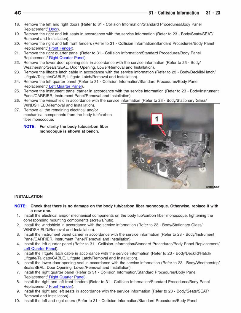
27. Remove all the remaining electrical and/or
mechanical components from the body tub/carbon
fiber monocoque.
NOTE: For clarity the body tub/carbon fiber
monocoque is shown at bench.
INSTALLATION
NOTE: Check that there is no damage on the body tub/carbon fiber monocoque. Otherwise, replace it with
a new one.
1. Install the electrical and/or mechanical components on the body tub/carbon fiber monocoque, tightening the
corresponding mounting components (screws/nuts).
2. Install the windshield in accordance with the service information (Refer to 23 - Body/Stationary Glass/
WINDSHIELD/Removal and Installation).
3. Install the instrument panel carrier in accordance with the service information (Refer to 23 - Body/Instrument
Panel/CARRIER, Instrument Panel/Removal and Installation).
4. Install the left quarter panel (Refer to 31 - Collision Information/Standard Procedures/Body Panel Replacement/
Left Quarter Panel).
5. Install the liftgate latch cable in accordance with the service information (Refer to 23 - Body/Decklid/Hatch/
Liftgate/Tailgate/CABLE, Liftgate Latch/Removal and Installation).
6. Install the lower door opening seal in accordance with the service information (Refer to 23 - Body/Weatherstrip/
Seals/SEAL, Door Opening, Lower/Removal and Installation).
7. Install the right quarter panel (Refer to 31 - Collision Information/Standard Procedures/Body Panel
Replacement/ Right Quarter Panel).
8. Install the right and left front fenders (Refer to 31 - Collision Information/Standard Procedures/Body Panel
Replacement/ Front Fender).
9. Install the right and left seats in accordance with the service information (Refer to 23 - Body/Seats/SEAT/
Removal and Installation).
10. Install the left and right doors (Refer to 31 - Collision Information/Standard Procedures/Body Panel
4C 31 - Collision Information 31 - 23

Replacement/ Body Panel Replacement/Door).
11. Install the roof rain gutter molding in accordance with the service information (Refer to 23 - Body/Exterior/
MOLDING, Rain Gutter Roof/Removal and Installation).
12. Install the a-pillar rain gutter molding in accordance with the service information (Refer to 23 - Body/Exterior/
MOLDING, Rain Gutter A-pillar/Removal and Installation).
13. Install the liftgate trim in accordance with the service information Body/Decklid/Hatch/Liftgate/Tailgate/PANEL,
Trim, Liftgate/Removal and Installation).
14. Install the liftgate (Refer to 31 - Collision Information/Standard Procedures/Body Panel Replacement/ Liftgate).
15. Install the headliner in accordance with the service information (Refer to 23 - Body/Interior/HEADLINER/
Removal and Installation).
16. Install the rear floor console in accordance with the service information (Refer to 23 - Body/Interior/CONSOLE,
Rear Floor/Removal and Installation).
17. Install the center belly pan (Refer to 13 - Frame and Bumpers/Under Body Protection/BELLY PAN, Center/
Removal and Installation).
18. Install the rear fascia in accordance with the service information (Refer to 13 - Frame and Bumpers/Bumpers/
FASCIA, Rear/Removal and Installation).
19. Install the power unit with dual clutch transmission in accordance with the service information (Refer to 09 -
Engine/Power Unit With Dual Clutch Transmission/Removal and Installation).
20. Install the fuel tank in accordance with the service information (Refer to 14 - Fuel System/Fuel Delivery, Gas/
TANK, Fuel/Removal and Installation) .
21. Install the right front headlamp cluster unit in accordance with the service information (Refer to 08 - Electrical/
Lamps/Lighting - Exterior/CLUSTER, Front Light, Left or Right/Removal and Installation).
22. Install the left front headlamp cluster unit in accordance with the service information (Refer to 08 - Electrical/
Lamps/Lighting - Exterior/CLUSTER, Front Light, Left or Right/Removal and Installation).
23. Install the engine cooling radiator in accordance with the service information (Refer to 07 - Cooling/Engine/
RADIATOR, Engine Cooling/Removal and Installation).
24. Install the passenger side footrest in accordance with the service information (Refer to 23 - Body/Interior/
FOOTREST/Removal and Installation).
25. Fill the transmission fluid in accordance with the service information (Refer to 21 - Transmission and Transfer
Case/Automatic - C635 DDCT/FLUID/Standard Procedure).
26. Fill the brake and/or clutch fluid in accordance with the service information (Refer to 05 - Brakes, Base/
Standard Procedure/Brake and/or Clutch Fluid Check Level and Top Up As Necessary).
27. Bleed the brake system in accordance with the service information (Refer to 05 - Brakes, Base/Standard
Procedure/Brake and/or Clutch Fluid Check Level and Top Up As Necessary).
28. Remove the support and lower the vehicle.
29. Check the front wheels geometry and adjust if necessary in accordance with the service information (Refer to
02 - Front Suspension/Wheel Alignment/Standard Procedure).
30. Check the rear wheels geometry and adjust if necessary in accordance with the service information (Refer to
02 - Front Suspension/Wheel Alignment/Standard Procedure).
31. Check the front headlamps cluster light beam position and adjust if necessary in accordance with the service
information (Refer to 08 - Electrical/Lamps/Lighting - Exterior/Standard Procedure).
31 - 24 31 - Collision Information 4C
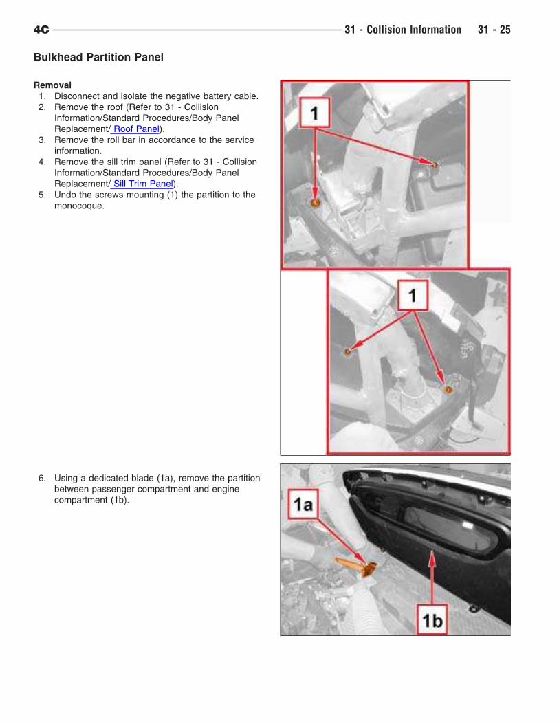
Bulkhead Partition Panel
Removal
1. Disconnect and isolate the negative battery cable.
2. Remove the roof (Refer to 31 - Collision
Information/Standard Procedures/Body Panel
Replacement/ Roof Panel).
3. Remove the roll bar in accordance to the service
information.
4. Remove the sill trim panel (Refer to 31 - Collision
Information/Standard Procedures/Body Panel
Replacement/ Sill Trim Panel).
5. Undo the screws mounting (1) the partition to the
monocoque.
6. Using a dedicated blade (1a), remove the partition
between passenger compartment and engine
compartment (1b).
4C 31 - Collision Information 31 - 25
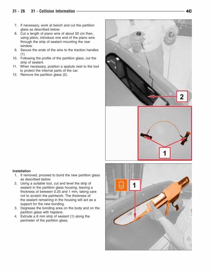
7. If necessary, work at bench and cut the partition
glass as described below:
8. Cut a length of piano wire of about 50 cm then,
using pliers, introduce one end of the piano wire
through the strip of sealant mounting the rear
window.
9. Secure the ends of the wire to the traction handles
(1).
10. Following the profile of the partition glass, cut the
strip of sealant.
11. When necessary, position a spatula next to the tool
to protect the internal parts of the car.
12. Remove the partition glass (2).
Installation
1. If removed, proceed to bond the new partition glass
as described below:
2. Using a suitable tool, cut and level the strip of
sealant in the partition glass housing, leaving a
thickness of between 0.25 and 1 mm, taking care
not to scratch the paintwork. The thickness of
the sealant remaining in the housing will act as a
support for the new bonding.
3. Degrease the bonding area on the body and on the
partition glass with heptane.
4. Extrude a 6 mm strip of sealant (1) along the
perimeter of the partition glass.
31 - 26 31 - Collision Information 4C
Component Type Name Classification Quantity Validity
– Sealant SIMSON ISR70–08P
– – –
5. Gently position the partition glass.
6. Wait for approximately 45 minutes before proceeding to install the partition in its housing.
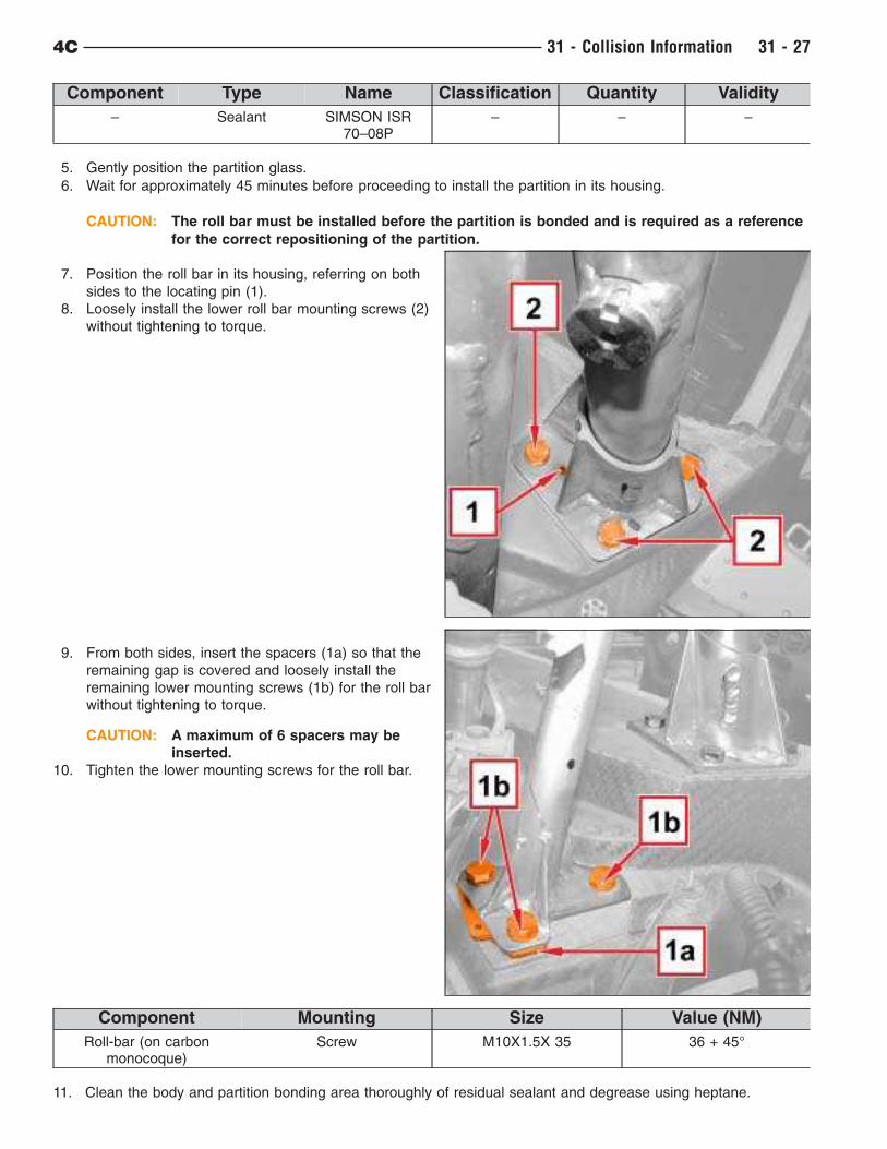
CAUTION: The roll bar must be installed before the partition is bonded and is required as a reference
for the correct repositioning of the partition.
7. Position the roll bar in its housing, referring on both
sides to the locating pin (1).
8. Loosely install the lower roll bar mounting screws (2)
without tightening to torque.
9. From both sides, insert the spacers (1a) so that the
remaining gap is covered and loosely install the
remaining lower mounting screws (1b) for the roll bar
without tightening to torque.
CAUTION: A maximum of 6 spacers may be
inserted.
10. Tighten the lower mounting screws for the roll bar.
Component Mounting Size Value (NM)
Roll-bar (on carbonmonocoque)
Screw M10X1.5X 35 36 + 45°
11. Clean the body and partition bonding area thoroughly of residual sealant and degrease using heptane.
4C 31 - Collision Information 31 - 27
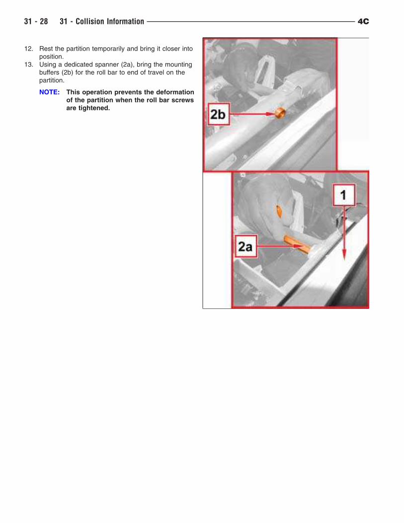
12. Rest the partition temporarily and bring it closer into
position.
13. Using a dedicated spanner (2a), bring the mounting
buffers (2b) for the roll bar to end of travel on the
partition.
NOTE: This operation prevents the deformation
of the partition when the roll bar screws
are tightened.
31 - 28 31 - Collision Information 4C
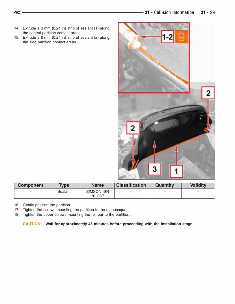
14. Extrude a 6 mm (0.24 in) strip of sealant (1) along
the central partition contact area.
15. Extrude a 6 mm (0.24 in) strip of sealant (2) along
the side partition contact areas.
Component Type Name Classification Quantity Validity
– Sealant SIMSON ISR70–08P
– – –
16. Gently position the partition.
17. Tighten the screws mounting the partition to the monocoque.
18. Tighten the upper screws mounting the roll bar to the partition.
CAUTION: Wait for approximately 45 minutes before proceeding with the installation stage.
4C 31 - Collision Information 31 - 29
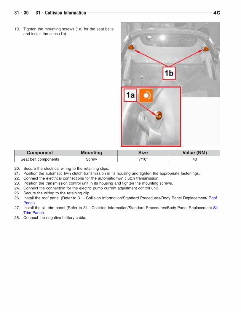
19. Tighten the mounting screws (1a) for the seat belts
and install the caps (1b).
Component Mounting Size Value (NM)
Seat belt components Screw 7/16” 40
20. Secure the electrical wiring to the retaining clips.
21. Position the automatic twin clutch transmission in its housing and tighten the appropriate fastenings.
22. Connect the electrical connections for the automatic twin clutch transmission.
23. Position the transmission control unit in its housing and tighten the mounting screws.
24. Connect the connection for the electric pump current adjustment control unit.
25. Secure the wiring to the retaining clip.
26. Install the roof panel (Refer to 31 - Collision Information/Standard Procedures/Body Panel Replacement/ Roof
Panel).
27. Install the sill trim panel (Refer to 31 - Collision Information/Standard Procedures/Body Panel Replacement Sill
Trim Panel).
28. Connect the negative battery cable.
31 - 30 31 - Collision Information 4C
Door
REMOVAL
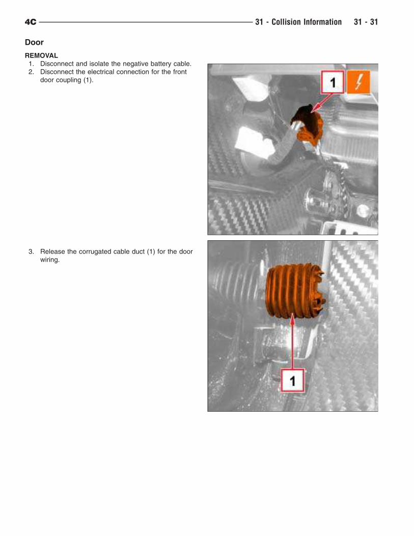
1. Disconnect and isolate the negative battery cable.
2. Disconnect the electrical connection for the front
door coupling (1).
3. Release the corrugated cable duct (1) for the door
wiring.
4C 31 - Collision Information 31 - 31
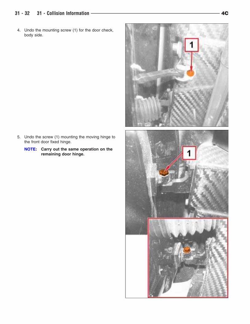
4. Undo the mounting screw (1) for the door check,
body side.
5. Undo the screw (1) mounting the moving hinge to
the front door fixed hinge.
NOTE: Carry out the same operation on the
remaining door hinge.
31 - 32 31 - Collision Information 4C
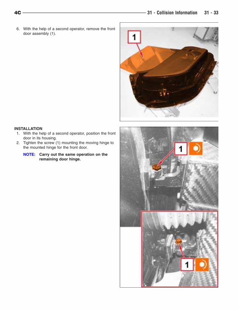
6. With the help of a second operator, remove the front
door assembly (1).
INSTALLATION
1. With the help of a second operator, position the front
door in its housing.
2. Tighten the screw (1) mounting the moving hinge to
the mounted hinge for the front door.
NOTE: Carry out the same operation on the
remaining door hinge.
4C 31 - Collision Information 31 - 33
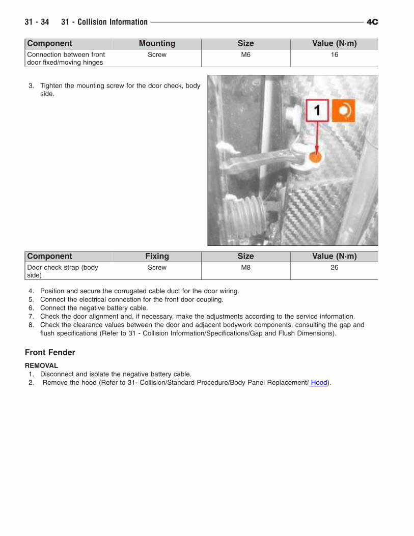
Component Mounting Size Value (N·m)
Connection between frontdoor fixed/moving hinges
Screw M6 16
3. Tighten the mounting screw for the door check, body
side.
Component Fixing Size Value (N·m)
Door check strap (bodyside)
Screw M8 26
4. Position and secure the corrugated cable duct for the door wiring.
5. Connect the electrical connection for the front door coupling.
6. Connect the negative battery cable.
7. Check the door alignment and, if necessary, make the adjustments according to the service information.
8. Check the clearance values between the door and adjacent bodywork components, consulting the gap and
flush specifications (Refer to 31 - Collision Information/Specifications/Gap and Flush Dimensions).
Front Fender
REMOVAL
1. Disconnect and isolate the negative battery cable.
2. Remove the hood (Refer to 31- Collision/Standard Procedure/Body Panel Replacement/ Hood).
31 - 34 31 - Collision Information 4C
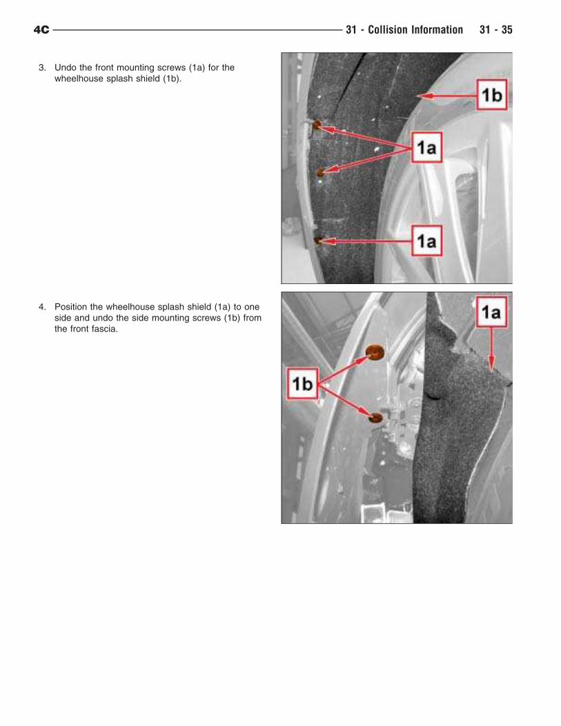
3. Undo the front mounting screws (1a) for the
wheelhouse splash shield (1b).
4. Position the wheelhouse splash shield (1a) to one
side and undo the side mounting screws (1b) from
the front fascia.
4C 31 - Collision Information 31 - 35
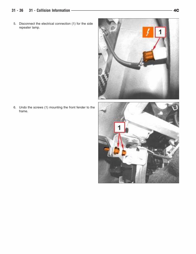
5. Disconnect the electrical connection (1) for the side
repeater lamp.
6. Undo the screws (1) mounting the front fender to the
frame.
31 - 36 31 - Collision Information 4C
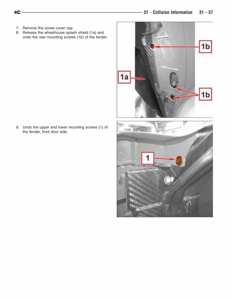
7. Remove the screw cover cap.
8. Release the wheelhouse splash shield (1a) and
undo the rear mounting screws (1b) of the fender.
9. Undo the upper and lower mounting screws (1) of
the fender, front door side.
4C 31 - Collision Information 31 - 37
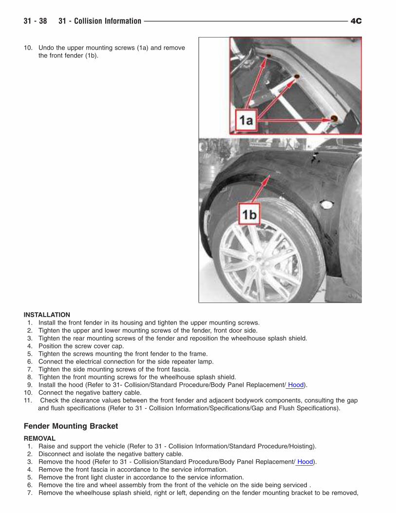
10. Undo the upper mounting screws (1a) and remove
the front fender (1b).
INSTALLATION
1. Install the front fender in its housing and tighten the upper mounting screws.
2. Tighten the upper and lower mounting screws of the fender, front door side.
3. Tighten the rear mounting screws of the fender and reposition the wheelhouse splash shield.
4. Position the screw cover cap.
5. Tighten the screws mounting the front fender to the frame.
6. Connect the electrical connection for the side repeater lamp.
7. Tighten the side mounting screws of the front fascia.
8. Tighten the front mounting screws for the wheelhouse splash shield.
9. Install the hood (Refer to 31- Collision/Standard Procedure/Body Panel Replacement/ Hood).
10. Connect the negative battery cable.
11. Check the clearance values between the front fender and adjacent bodywork components, consulting the gap
and flush specifications (Refer to 31 - Collision Information/Specifications/Gap and Flush Specifications).
Fender Mounting Bracket
REMOVAL
1. Raise and support the vehicle (Refer to 31 - Collision Information/Standard Procedure/Hoisting).
2. Disconnect and isolate the negative battery cable.
3. Remove the hood (Refer to 31 - Collision/Standard Procedure/Body Panel Replacement/ Hood).
4. Remove the front fascia in accordance to the service information.
5. Remove the front light cluster in accordance to the service information.
6. Remove the tire and wheel assembly from the front of the vehicle on the side being serviced .
7. Remove the wheelhouse splash shield, right or left, depending on the fender mounting bracket to be removed,
31 - 38 31 - Collision Information 4C
in accordance to the service information.
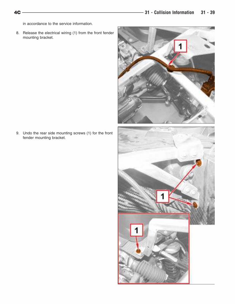
8. Release the electrical wiring (1) from the front fender
mounting bracket.
9. Undo the rear side mounting screws (1) for the front
fender mounting bracket.
4C 31 - Collision Information 31 - 39
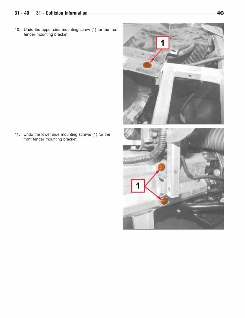
10. Undo the upper side mounting screw (1) for the front
fender mounting bracket.
11. Undo the lower side mounting screws (1) for the
front fender mounting bracket.
31 - 40 31 - Collision Information 4C
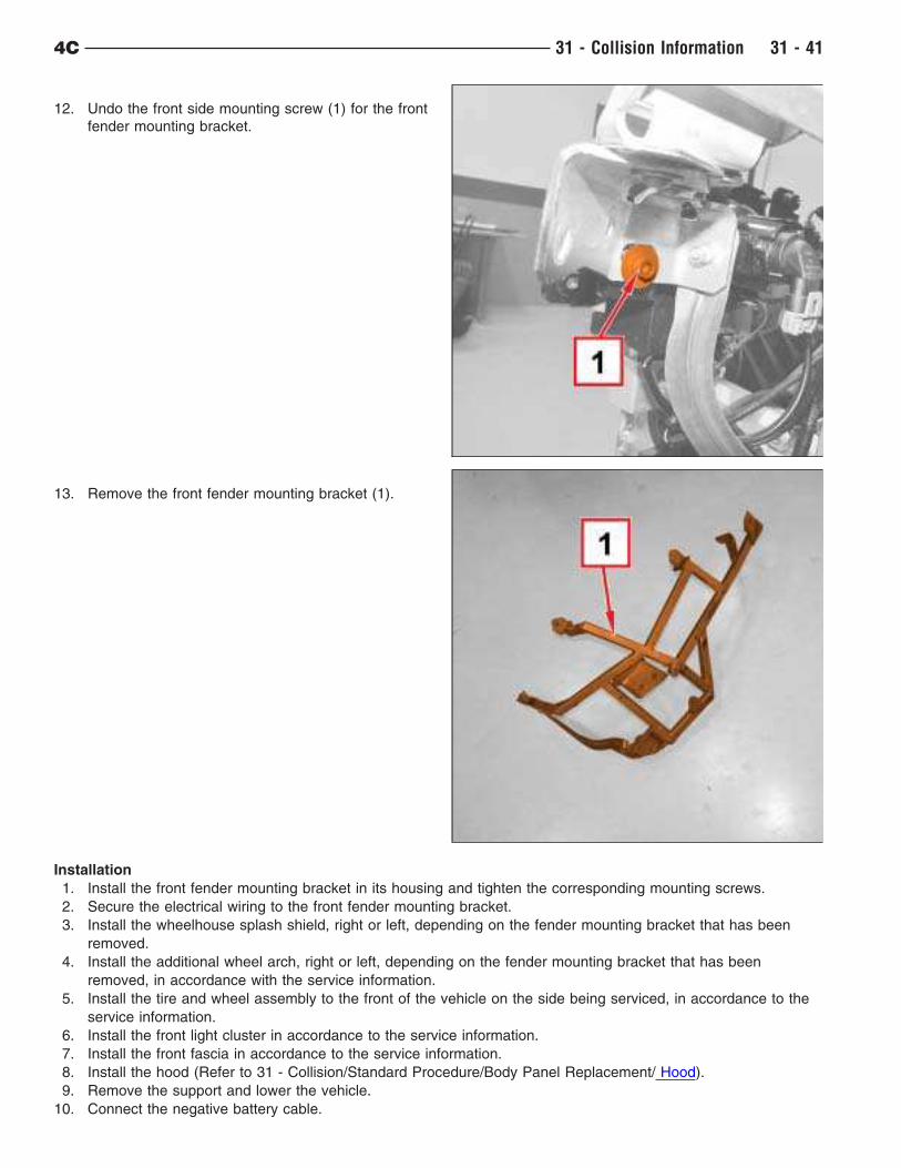
12. Undo the front side mounting screw (1) for the front
fender mounting bracket.
13. Remove the front fender mounting bracket (1).
Installation
1. Install the front fender mounting bracket in its housing and tighten the corresponding mounting screws.
2. Secure the electrical wiring to the front fender mounting bracket.
3. Install the wheelhouse splash shield, right or left, depending on the fender mounting bracket that has been
removed.
4. Install the additional wheel arch, right or left, depending on the fender mounting bracket that has been
removed, in accordance with the service information.
5. Install the tire and wheel assembly to the front of the vehicle on the side being serviced, in accordance to the
service information.
6. Install the front light cluster in accordance to the service information.
7. Install the front fascia in accordance to the service information.
8. Install the hood (Refer to 31 - Collision/Standard Procedure/Body Panel Replacement/ Hood).
9. Remove the support and lower the vehicle.
10. Connect the negative battery cable.
4C 31 - Collision Information 31 - 41
Hood
REMOVAL
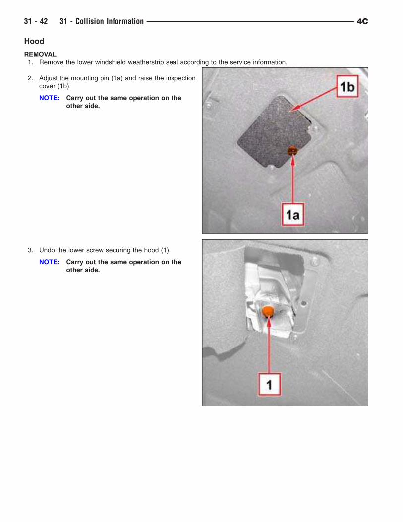
1. Remove the lower windshield weatherstrip seal according to the service information.
2. Adjust the mounting pin (1a) and raise the inspection
cover (1b).
NOTE: Carry out the same operation on the
other side.
3. Undo the lower screw securing the hood (1).
NOTE: Carry out the same operation on the
other side.
31 - 42 31 - Collision Information 4C
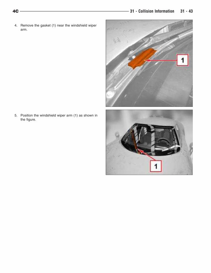
4. Remove the gasket (1) near the windshield wiper
arm.
5. Position the windshield wiper arm (1) as shown in
the figure.
4C 31 - Collision Information 31 - 43
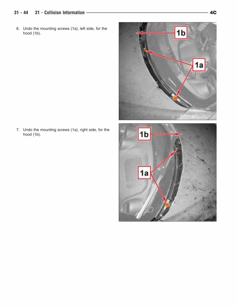
6. Undo the mounting screws (1a), left side, for the
hood (1b).
7. Undo the mounting screws (1a), right side, for the
hood (1b).
31 - 44 31 - Collision Information 4C
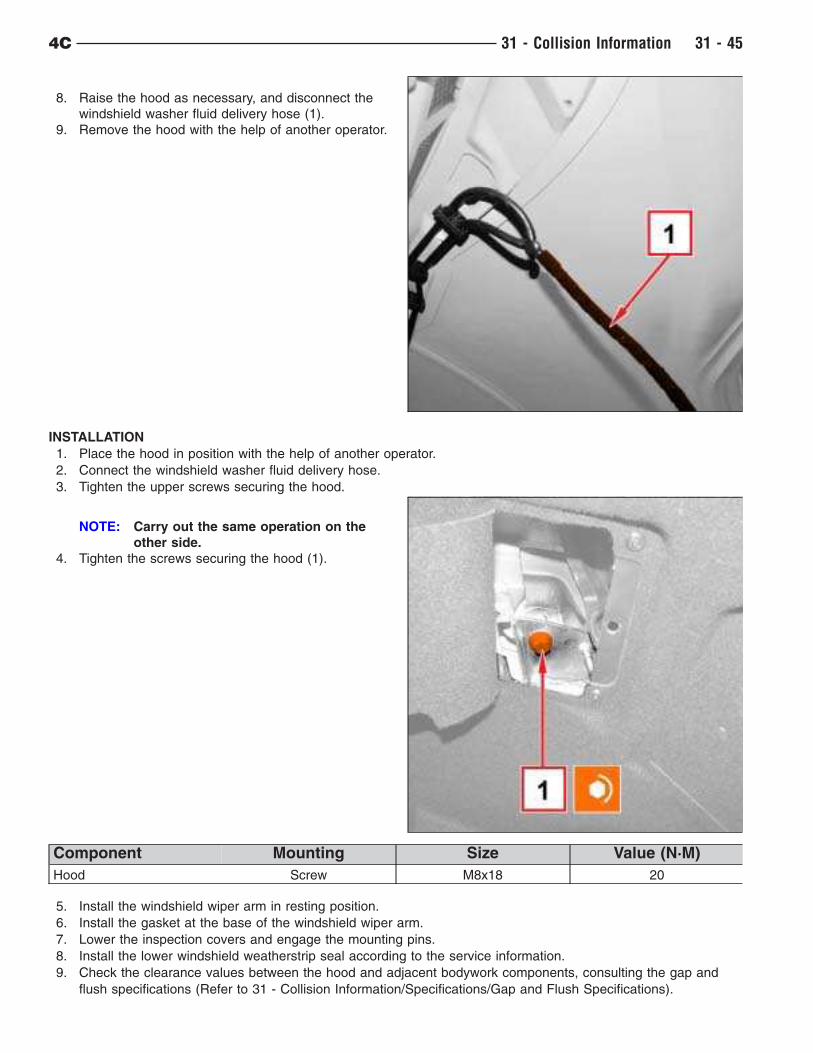
8. Raise the hood as necessary, and disconnect the
windshield washer fluid delivery hose (1).
9. Remove the hood with the help of another operator.
INSTALLATION
1. Place the hood in position with the help of another operator.
2. Connect the windshield washer fluid delivery hose.
3. Tighten the upper screws securing the hood.
NOTE: Carry out the same operation on the
other side.
4. Tighten the screws securing the hood (1).
Component Mounting Size Value (N·M)
Hood Screw M8x18 20
5. Install the windshield wiper arm in resting position.
6. Install the gasket at the base of the windshield wiper arm.
7. Lower the inspection covers and engage the mounting pins.
8. Install the lower windshield weatherstrip seal according to the service information.
9. Check the clearance values between the hood and adjacent bodywork components, consulting the gap and
flush specifications (Refer to 31 - Collision Information/Specifications/Gap and Flush Specifications).
4C 31 - Collision Information 31 - 45
Liftgate
REMOVAL
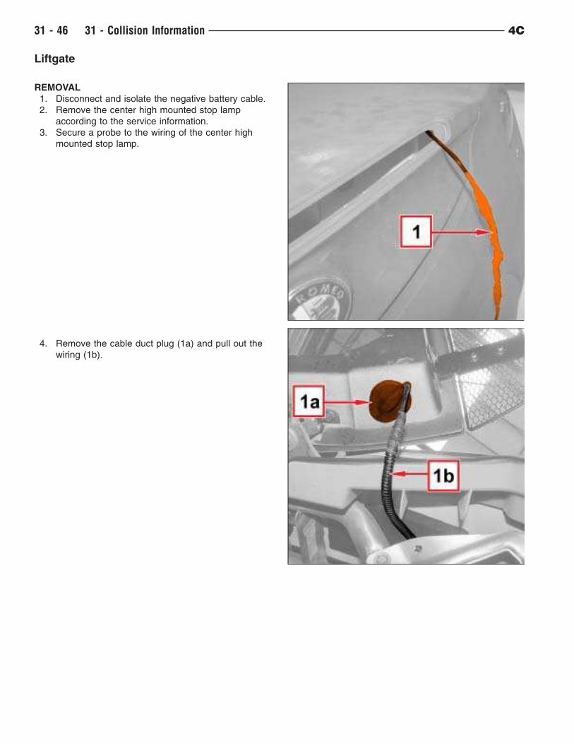
1. Disconnect and isolate the negative battery cable.
2. Remove the center high mounted stop lamp
according to the service information.
3. Secure a probe to the wiring of the center high
mounted stop lamp.
4. Remove the cable duct plug (1a) and pull out the
wiring (1b).
31 - 46 31 - Collision Information 4C
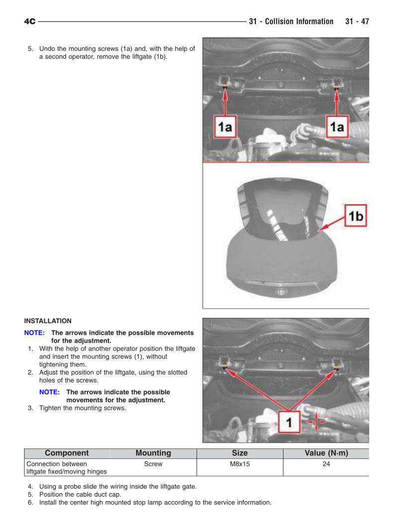
5. Undo the mounting screws (1a) and, with the help of
a second operator, remove the liftgate (1b).
INSTALLATION
NOTE: The arrows indicate the possible movements
for the adjustment.
1. With the help of another operator position the liftgate
and insert the mounting screws (1), without
tightening them.
2. Adjust the position of the liftgate, using the slotted
holes of the screws.
NOTE: The arrows indicate the possible
movements for the adjustment.
3. Tighten the mounting screws.
Component Mounting Size Value (N·m)
Connection betweenliftgate fixed/moving hinges
Screw M8x15 24
4. Using a probe slide the wiring inside the liftgate gate.
5. Position the cable duct cap.
6. Install the center high mounted stop lamp according to the service information.
4C 31 - Collision Information 31 - 47
7. Connect the negative battery cable.
8. Check the clearance values between the liftgate and adjacent bodywork components, consulting the gap and
flush specifications (Refer to 31 - Collision Information/Specifications/Gap and Flush Specifications).
Sill Trim Panel
REMOVAL
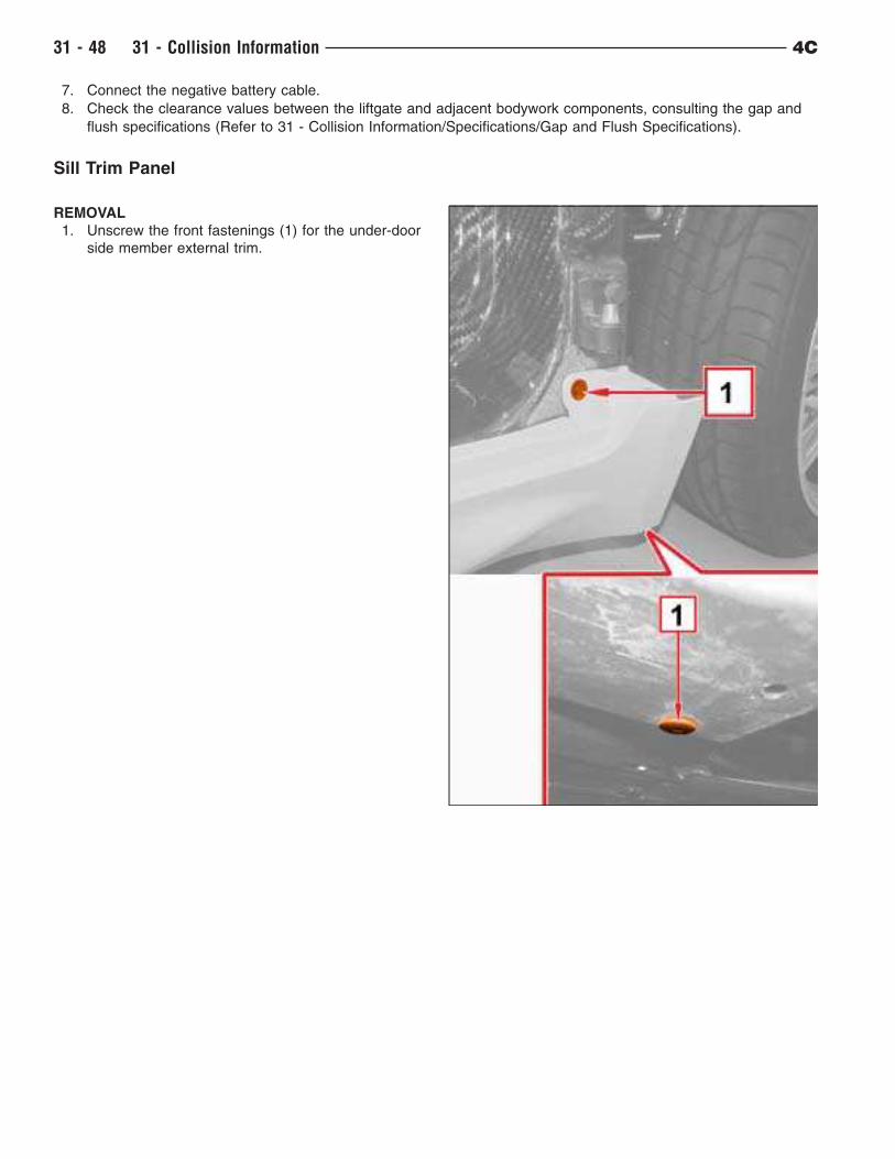
1. Unscrew the front fastenings (1) for the under-door
side member external trim.
31 - 48 31 - Collision Information 4C
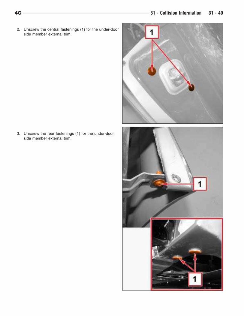
2. Unscrew the central fastenings (1) for the under-door
side member external trim.
3. Unscrew the rear fastenings (1) for the under-door
side member external trim.
4C 31 - Collision Information 31 - 49
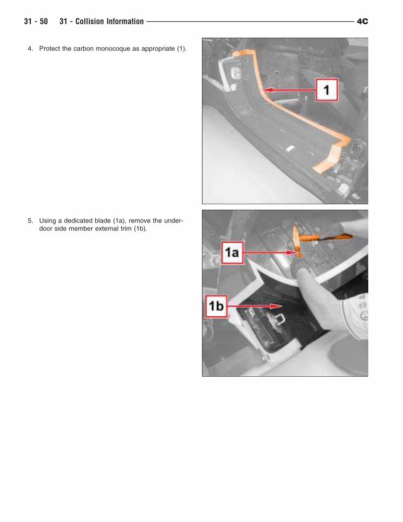
4. Protect the carbon monocoque as appropriate (1).
5. Using a dedicated blade (1a), remove the under-
door side member external trim (1b).
31 - 50 31 - Collision Information 4C
Installation
1. Clean the body and under-door side member
external trim bonding areas thoroughly of residual
sealant and degrease using heptane.
2. Extrude a 6 mm strip of structural adhesive (1) along
the perimeter which comes into contact with the
under-door side member external trim as shown in
the figure.
NOTE: Use approved structural repair adhesive
– Lord Fusor 112 or 3M 08116
Component Type Name Classification Quantity Validity
– StructuralAdhesive
Lord Fusor 112or 3M 08116
– – –
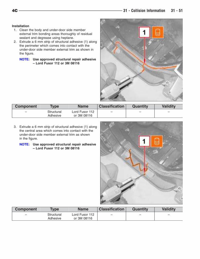
3. Extrude a 6 mm strip of structural adhesive (1) along
the central area which comes into contact with the
under-door side member external trim as shown
in the figure.
NOTE: Use approved structural repair adhesive
– Lord Fusor 112 or 3M 08116
Component Type Name Classification Quantity Validity
– StructuralAdhesive
Lord Fusor 112or 3M 08116
– – –
4C 31 - Collision Information 31 - 51
4. Gently position the side member external trim.
5. Position some adhesive tape (1) to facilitate the
bonding of the side member external trim to the
monocoque.
6. Tighten the rear fastenings for the under-door side
member external trim.
7. Tighten the central fastenings for the under-door side
member external trim.
8. Tighten the front fastenings for the under-door side
member external trim.
CAUTION: Follow adhesive manufacturer
guidelines and wait the appropriate
time before proceeding with any
other operations.
Left Quarter Panel
REMOVAL
1. Raise and support the vehicle (Refer to 31 - Collision Information/Specifications/Hoisting).
2. Remove the tire and wheel assembly from the left rear of the vehicle in accordance to the service information.
3. Remove the left rear wheelhouse splash shield in accordance to the service information.
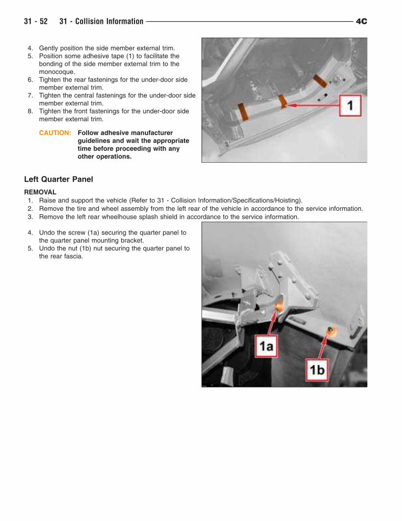
4. Undo the screw (1a) securing the quarter panel to
the quarter panel mounting bracket.
5. Undo the nut (1b) nut securing the quarter panel to
the rear fascia.
31 - 52 31 - Collision Information 4C
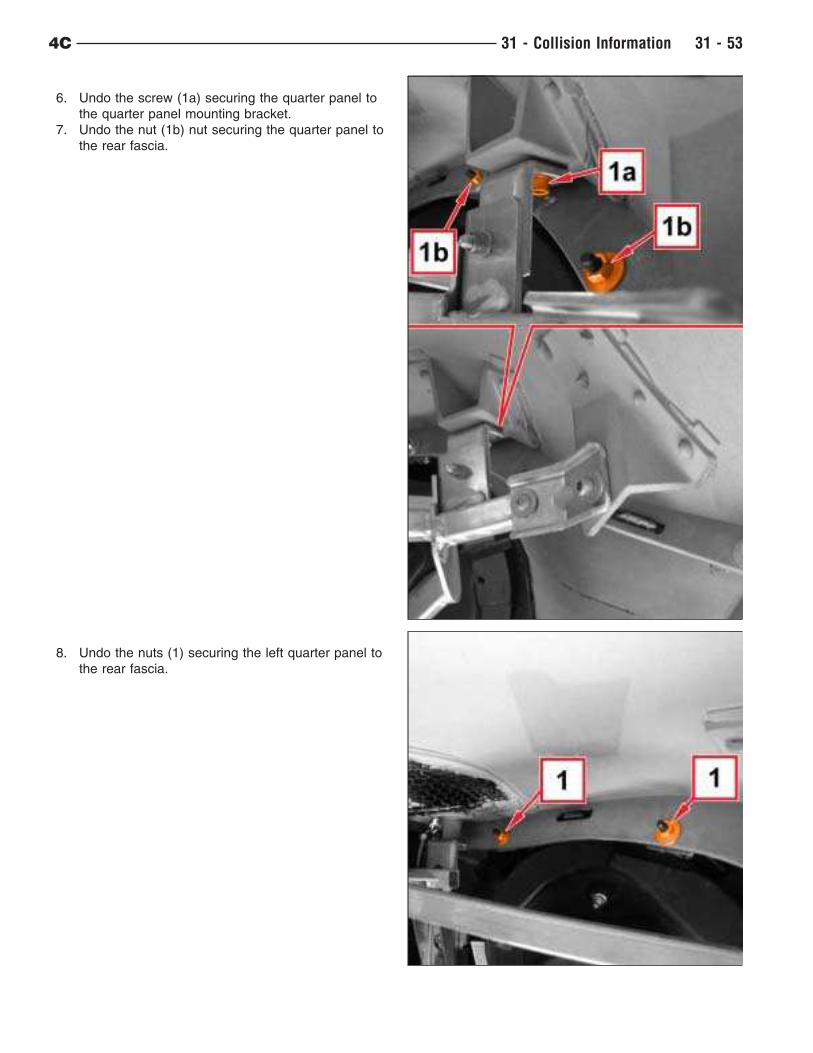
6. Undo the screw (1a) securing the quarter panel to
the quarter panel mounting bracket.
7. Undo the nut (1b) nut securing the quarter panel to
the rear fascia.
8. Undo the nuts (1) securing the left quarter panel to
the rear fascia.
4C 31 - Collision Information 31 - 53
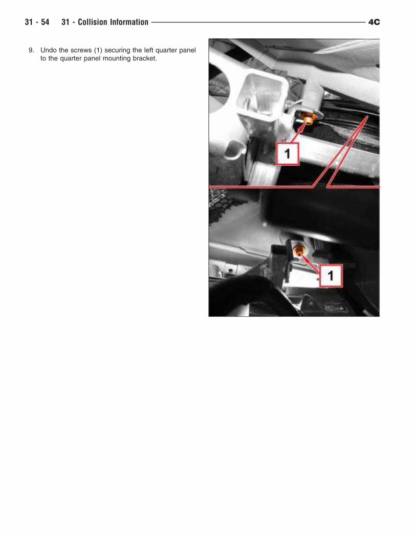
9. Undo the screws (1) securing the left quarter panel
to the quarter panel mounting bracket.
31 - 54 31 - Collision Information 4C
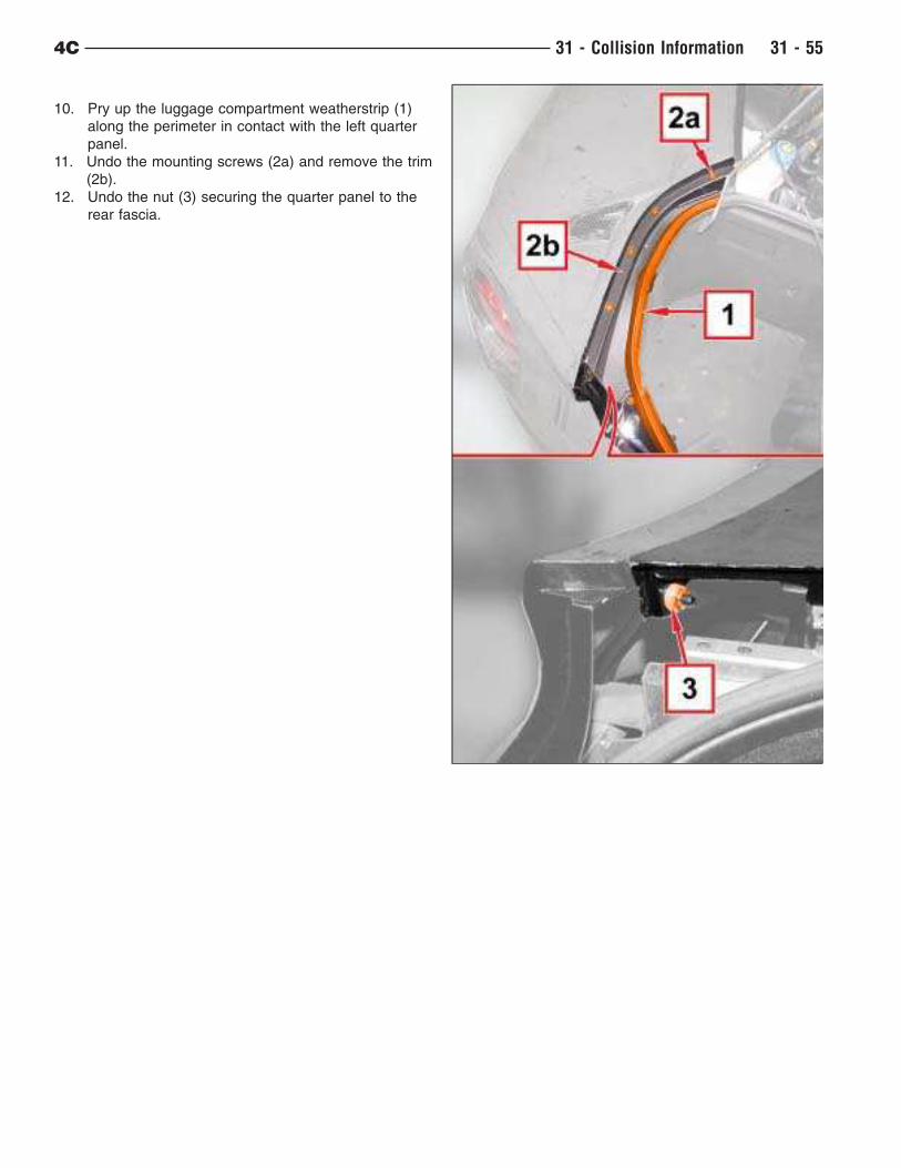
10. Pry up the luggage compartment weatherstrip (1)
along the perimeter in contact with the left quarter
panel.
11. Undo the mounting screws (2a) and remove the trim
(2b).
12. Undo the nut (3) securing the quarter panel to the
rear fascia.
4C 31 - Collision Information 31 - 55
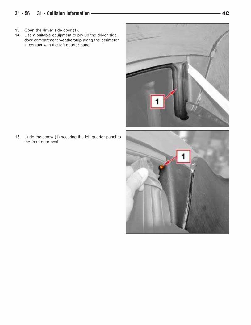
13. Open the driver side door (1).
14. Use a suitable equipment to pry up the driver side
door compartment weatherstrip along the perimeter
in contact with the left quarter panel.
15. Undo the screw (1) securing the left quarter panel to
the front door post.
31 - 56 31 - Collision Information 4C
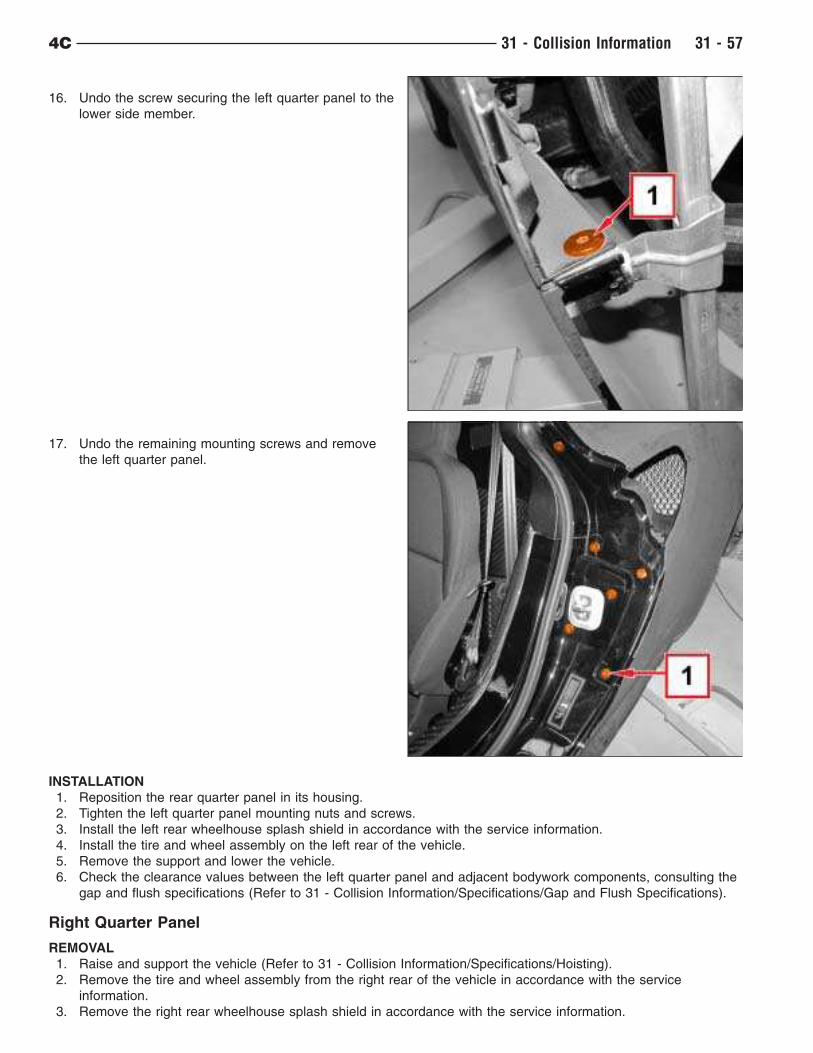
16. Undo the screw securing the left quarter panel to the
lower side member.
17. Undo the remaining mounting screws and remove
the left quarter panel.
INSTALLATION
1. Reposition the rear quarter panel in its housing.
2. Tighten the left quarter panel mounting nuts and screws.
3. Install the left rear wheelhouse splash shield in accordance with the service information.
4. Install the tire and wheel assembly on the left rear of the vehicle.
5. Remove the support and lower the vehicle.
6. Check the clearance values between the left quarter panel and adjacent bodywork components, consulting the
gap and flush specifications (Refer to 31 - Collision Information/Specifications/Gap and Flush Specifications).
Right Quarter Panel
REMOVAL
1. Raise and support the vehicle (Refer to 31 - Collision Information/Specifications/Hoisting).
2. Remove the tire and wheel assembly from the right rear of the vehicle in accordance with the service
information.
3. Remove the right rear wheelhouse splash shield in accordance with the service information.
4C 31 - Collision Information 31 - 57
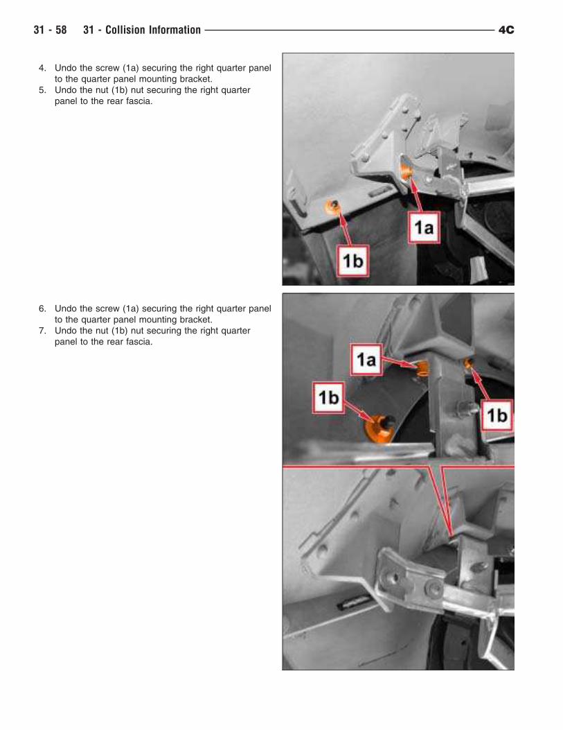
4. Undo the screw (1a) securing the right quarter panel
to the quarter panel mounting bracket.
5. Undo the nut (1b) nut securing the right quarter
panel to the rear fascia.
6. Undo the screw (1a) securing the right quarter panel
to the quarter panel mounting bracket.
7. Undo the nut (1b) nut securing the right quarter
panel to the rear fascia.
31 - 58 31 - Collision Information 4C
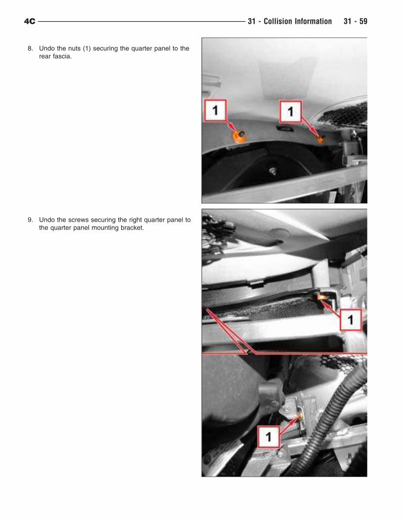
8. Undo the nuts (1) securing the quarter panel to the
rear fascia.
9. Undo the screws securing the right quarter panel to
the quarter panel mounting bracket.
4C 31 - Collision Information 31 - 59
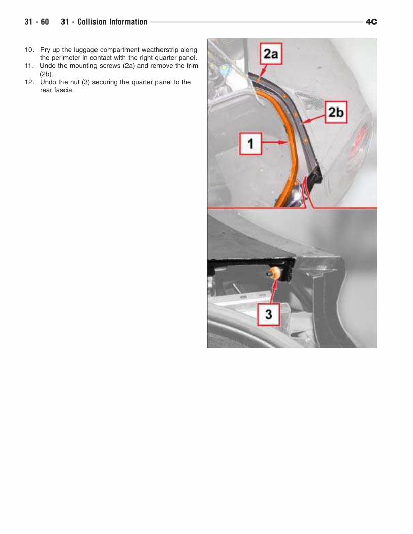
10. Pry up the luggage compartment weatherstrip along
the perimeter in contact with the right quarter panel.
11. Undo the mounting screws (2a) and remove the trim
(2b).
12. Undo the nut (3) securing the quarter panel to the
rear fascia.
31 - 60 31 - Collision Information 4C
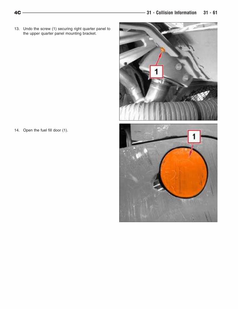
13. Undo the screw (1) securing right quarter panel to
the upper quarter panel mounting bracket.
14. Open the fuel fill door (1).
4C 31 - Collision Information 31 - 61
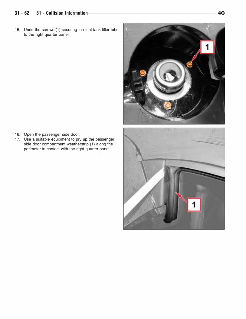
15. Undo the screws (1) securing the fuel tank filler tube
to the right quarter panel.
16. Open the passenger side door.
17. Use a suitable equipment to pry up the passenger
side door compartment weatherstrip (1) along the
perimeter in contact with the right quarter panel.
31 - 62 31 - Collision Information 4C
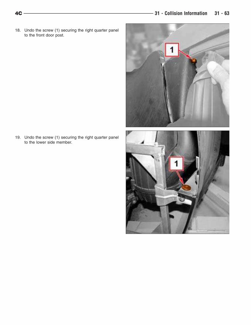
18. Undo the screw (1) securing the right quarter panel
to the front door post.
19. Undo the screw (1) securing the right quarter panel
to the lower side member.
4C 31 - Collision Information 31 - 63
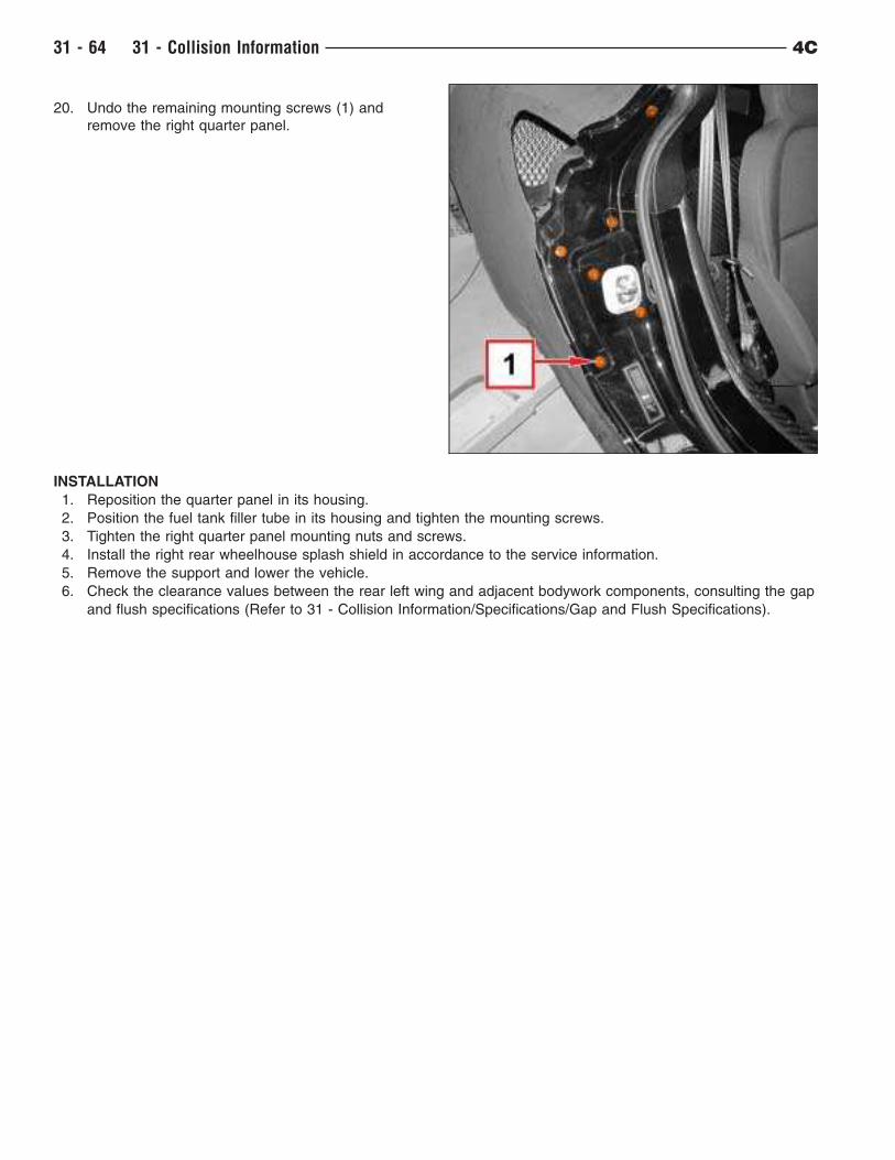
20. Undo the remaining mounting screws (1) and
remove the right quarter panel.
INSTALLATION
1. Reposition the quarter panel in its housing.
2. Position the fuel tank filler tube in its housing and tighten the mounting screws.
3. Tighten the right quarter panel mounting nuts and screws.
4. Install the right rear wheelhouse splash shield in accordance to the service information.
5. Remove the support and lower the vehicle.
6. Check the clearance values between the rear left wing and adjacent bodywork components, consulting the gap
and flush specifications (Refer to 31 - Collision Information/Specifications/Gap and Flush Specifications).
31 - 64 31 - Collision Information 4C
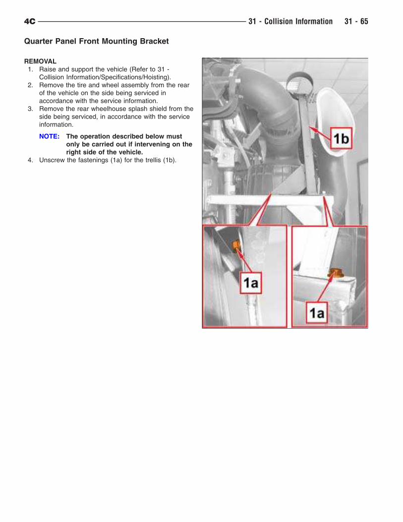
Quarter Panel Front Mounting Bracket
REMOVAL
1. Raise and support the vehicle (Refer to 31 -
Collision Information/Specifications/Hoisting).
2. Remove the tire and wheel assembly from the rear
of the vehicle on the side being serviced in
accordance with the service information.
3. Remove the rear wheelhouse splash shield from the
side being serviced, in accordance with the service
information.
NOTE: The operation described below must
only be carried out if intervening on the
right side of the vehicle.
4. Unscrew the fastenings (1a) for the trellis (1b).
4C 31 - Collision Information 31 - 65
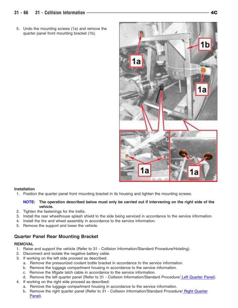
5. Undo the mounting screws (1a) and remove the
quarter panel front mounting bracket (1b).
Installation
1. Position the quarter panel front mounting bracket in its housing and tighten the mounting screws.
NOTE: The operation described below must only be carried out if intervening on the right side of the
vehicle.
2. Tighten the fastenings for the trellis.
3. Install the rear wheelhouse splash shield to the side being serviced in accordance to the service information.
4. Install the tire and wheel assembly in accordance to the service information.
5. Remove the support and lower the vehicle.
Quarter Panel Rear Mounting Bracket
REMOVAL
1. Raise and support the vehicle (Refer to 31 - Collision Information/Standard Procedure/Hoisting).
2. Disconnect and isolate the negative battery cable.
3. If working on the left side proceed as described:
a. Remove the pressurized coolant bottle bracket in accordance to the service information.
b. Remove the luggage compartment housing in accordance to the service information.
c. Remove the liftgate latch cable in accordance to the service information.
d. Remove the left quarter panel (Refer to 31 - Collision Information/Standard Procedure/ Left Quarter Panel).
4. If working on the right side proceed as described:
a. Remove the luggage compartment housing in accordance to the service information.
b. Remove the right quarter panel (Refer to 31 - Collision Information/Standard Procedure/ Right Quarter
Panel).
31 - 66 31 - Collision Information 4C
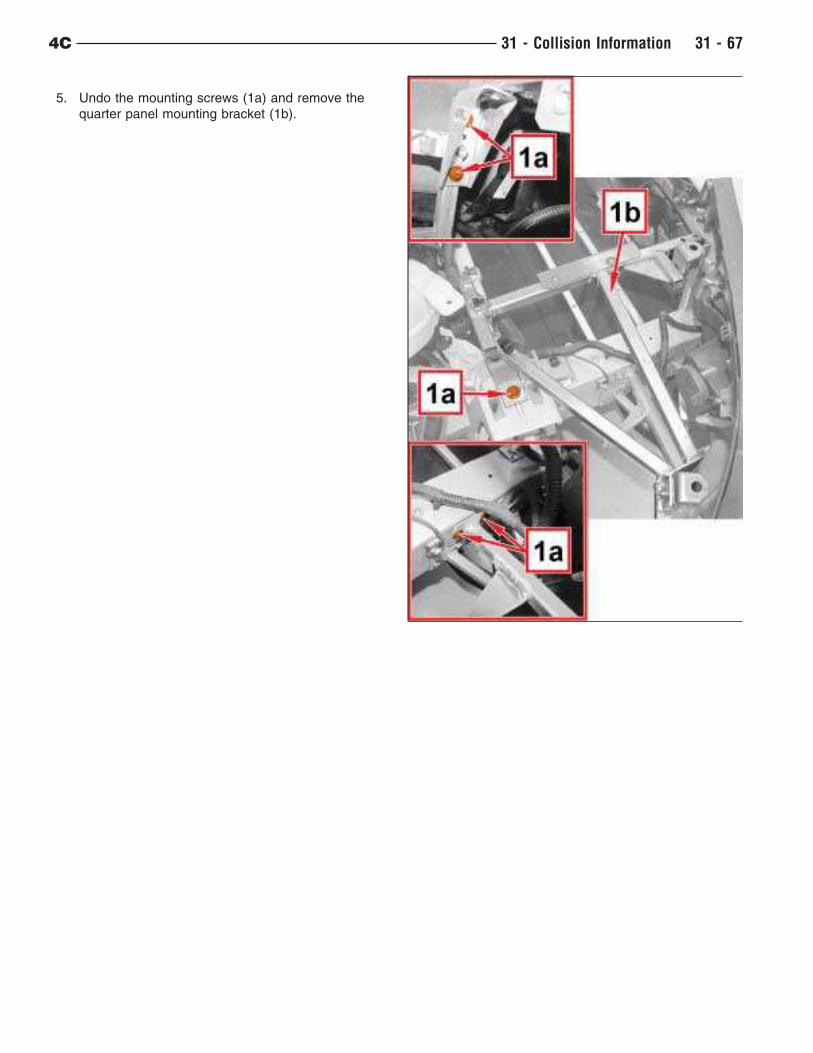
5. Undo the mounting screws (1a) and remove the
quarter panel mounting bracket (1b).
4C 31 - Collision Information 31 - 67
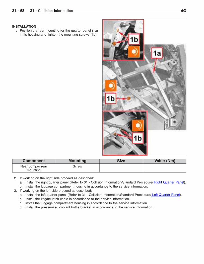
INSTALLATION
1. Position the rear mounting for the quarter panel (1a)
in its housing and tighten the mounting screws (1b).
Component Mounting Size Value (Nm)
Rear bumper rearmounting
Screw
2. If working on the right side proceed as described:
a. Install the right quarter panel (Refer to 31 - Collision Information/Standard Procedure/ Right Quarter Panel).
b. Install the luggage compartment housing in accordance to the service information.
3. If working on the left side proceed as described:
a. Install the left quarter panel (Refer to 31 - Collision Information/Standard Procedure/ Left Quarter Panel).
b. Install the liftgate latch cable in accordance to the service information.
c. Install the luggage compartment housing in accordance to the service information.
d. Install the pressurized coolant bottle bracket in accordance to the service information.
31 - 68 31 - Collision Information 4C
Roof Panel
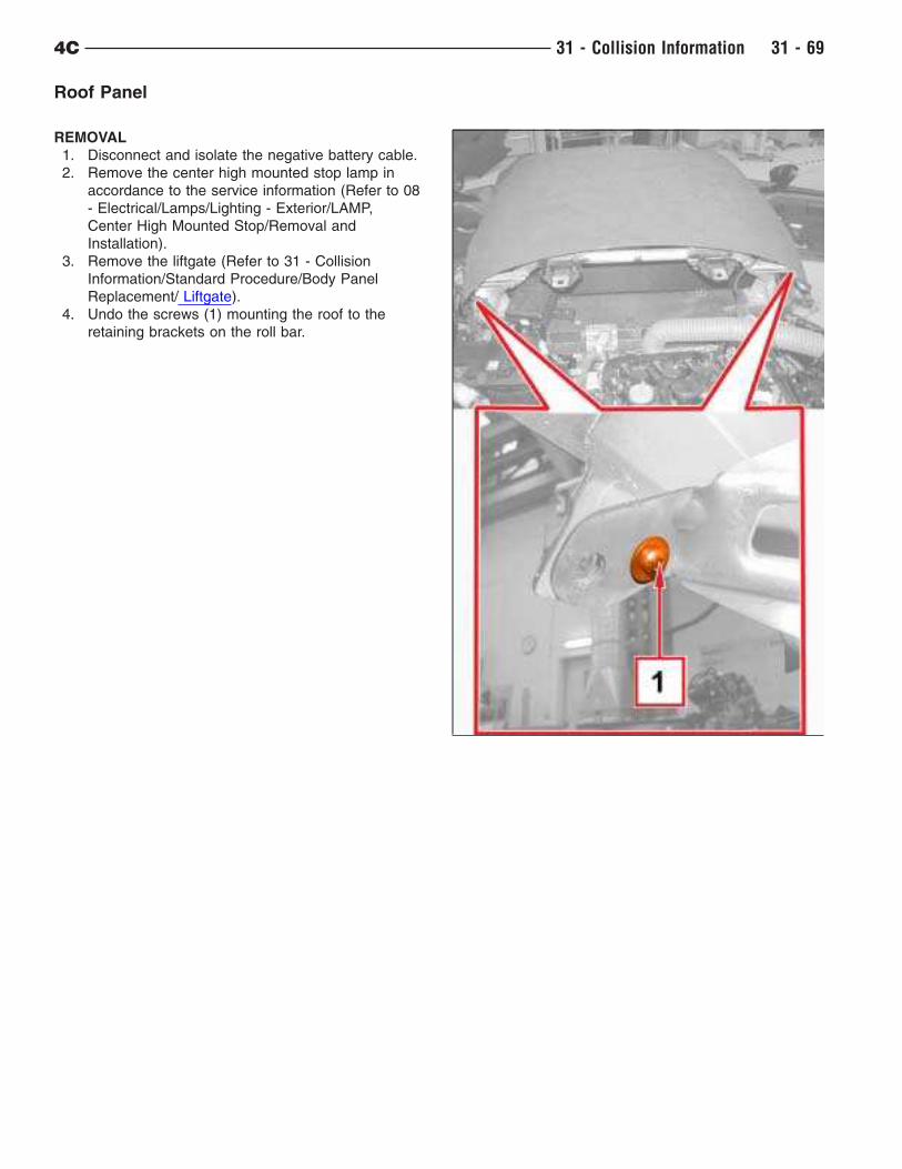
REMOVAL
1. Disconnect and isolate the negative battery cable.
2. Remove the center high mounted stop lamp in
accordance to the service information (Refer to 08
- Electrical/Lamps/Lighting - Exterior/LAMP,
Center High Mounted Stop/Removal and
Installation).
3. Remove the liftgate (Refer to 31 - Collision
Information/Standard Procedure/Body Panel
Replacement/ Liftgate).
4. Undo the screws (1) mounting the roof to the
retaining brackets on the roll bar.
4C 31 - Collision Information 31 - 69
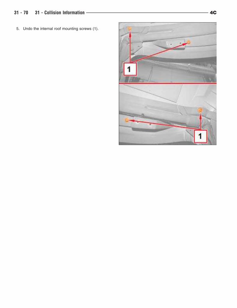
5. Undo the internal roof mounting screws (1).
31 - 70 31 - Collision Information 4C
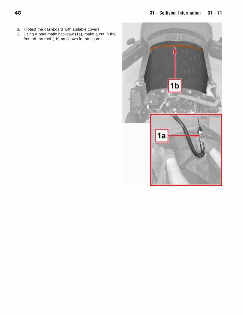
6. Protect the dashboard with suitable covers.
7. Using a pneumatic hacksaw (1a), make a cut in the
front of the roof (1b) as shown in the figure.
4C 31 - Collision Information 31 - 71
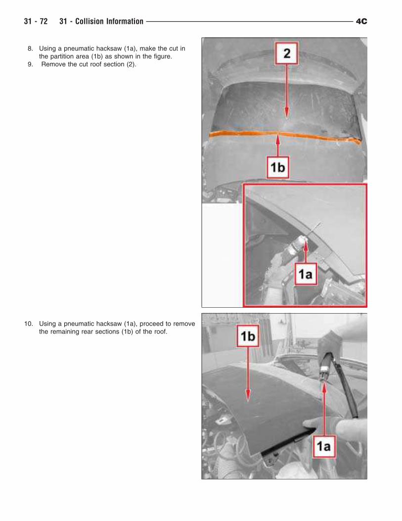
8. Using a pneumatic hacksaw (1a), make the cut in
the partition area (1b) as shown in the figure.
9. Remove the cut roof section (2).
10. Using a pneumatic hacksaw (1a), proceed to remove
the remaining rear sections (1b) of the roof.
31 - 72 31 - Collision Information 4C
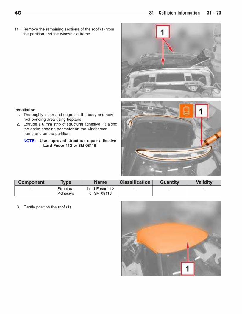
11. Remove the remaining sections of the roof (1) from
the partition and the windshield frame.
Installation
1. Thoroughly clean and degrease the body and new
roof bonding area using heptane.
2. Extrude a 6 mm strip of structural adhesive (1) along
the entire bonding perimeter on the windscreen
frame and on the partition.
NOTE: Use approved structural repair adhesive
– Lord Fusor 112 or 3M 08116
Component Type Name Classification Quantity Validity
– StructuralAdhesive
Lord Fusor 112or 3M 08116
– – –
3. Gently position the roof (1).
4C 31 - Collision Information 31 - 73
Windshield Frame
REMOVAL
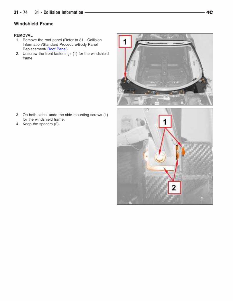
1. Remove the roof panel (Refer to 31 - Collision
Information/Standard Procedure/Body Panel
Replacement/ Roof Panel).
2. Unscrew the front fastenings (1) for the windshield
frame.
3. On both sides, undo the side mounting screws (1)
for the windshield frame.
4. Keep the spacers (2).
31 - 74 31 - Collision Information 4C
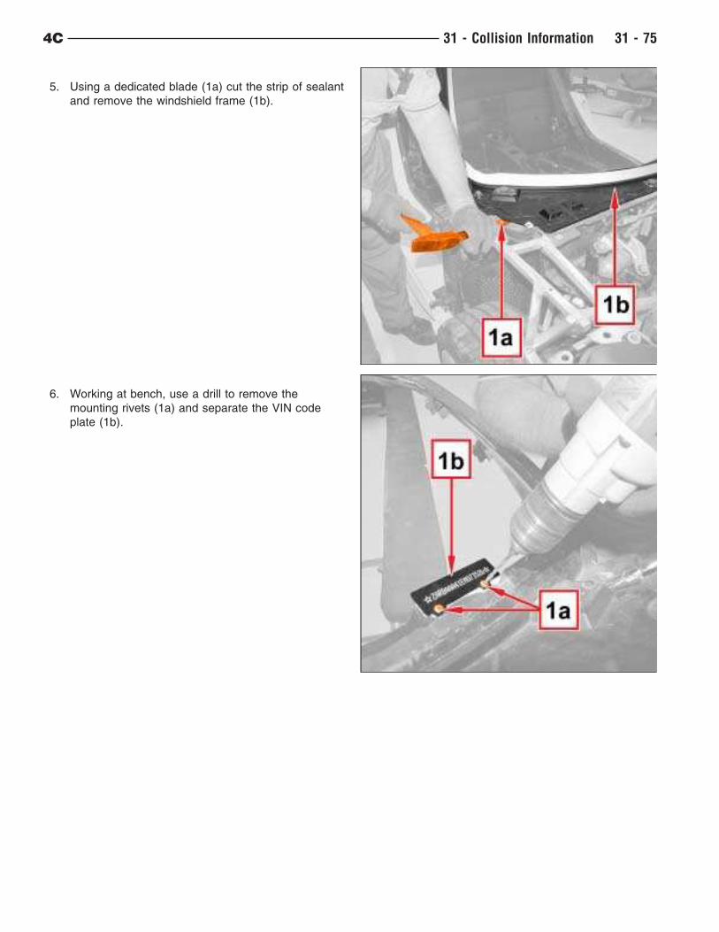
5. Using a dedicated blade (1a) cut the strip of sealant
and remove the windshield frame (1b).
6. Working at bench, use a drill to remove the
mounting rivets (1a) and separate the VIN code
plate (1b).
4C 31 - Collision Information 31 - 75
Installation
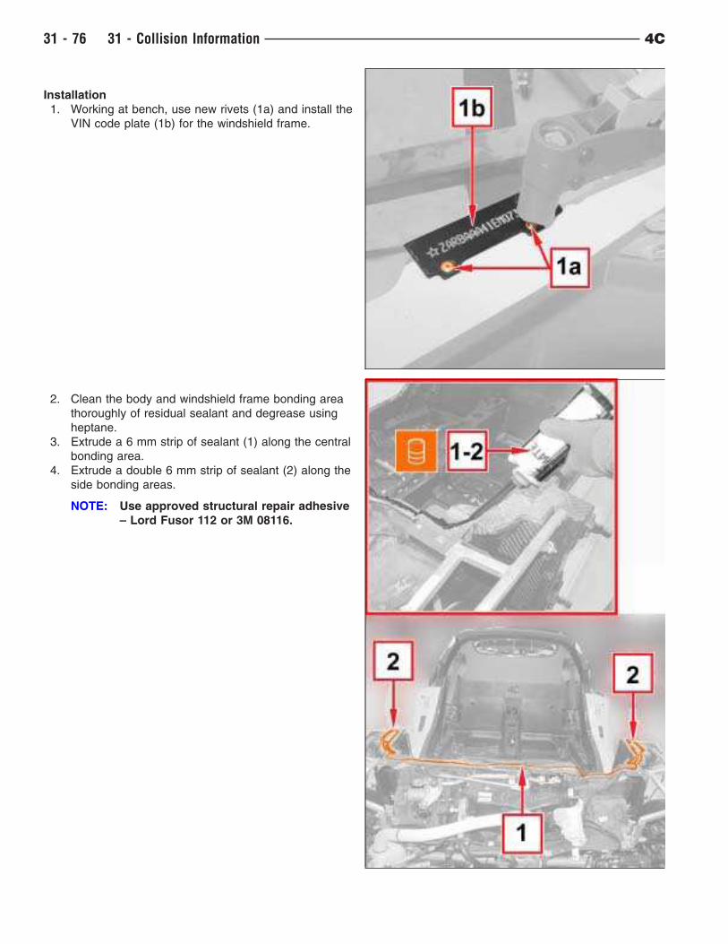
1. Working at bench, use new rivets (1a) and install the
VIN code plate (1b) for the windshield frame.
2. Clean the body and windshield frame bonding area
thoroughly of residual sealant and degrease using
heptane.
3. Extrude a 6 mm strip of sealant (1) along the central
bonding area.
4. Extrude a double 6 mm strip of sealant (2) along the
side bonding areas.
NOTE: Use approved structural repair adhesive
– Lord Fusor 112 or 3M 08116.
31 - 76 31 - Collision Information 4C
Component Type Name Classification Quantity Validity
– StructuralAdhesive
Lord Fusor 112or 3M 08116
– – –
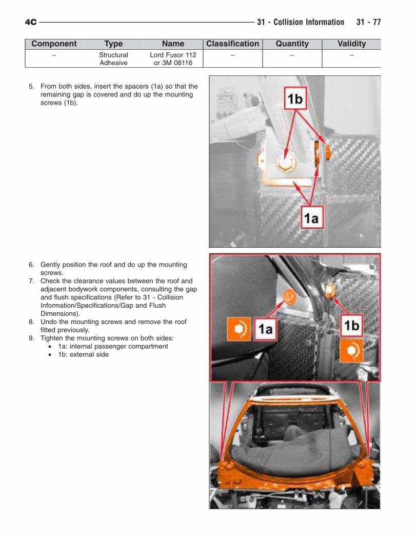
5. From both sides, insert the spacers (1a) so that the
remaining gap is covered and do up the mounting
screws (1b).
6. Gently position the roof and do up the mounting
screws.
7. Check the clearance values between the roof and
adjacent bodywork components, consulting the gap
and flush specifications (Refer to 31 - Collision
Information/Specifications/Gap and Flush
Dimensions).
8. Undo the mounting screws and remove the roof
fitted previously.
9. Tighten the mounting screws on both sides:
• 1a: internal passenger compartment
• 1b: external side
4C 31 - Collision Information 31 - 77
Component Mounting Size Value (NM)
Windshield frame Screw M10 X 1.25 X 35 51
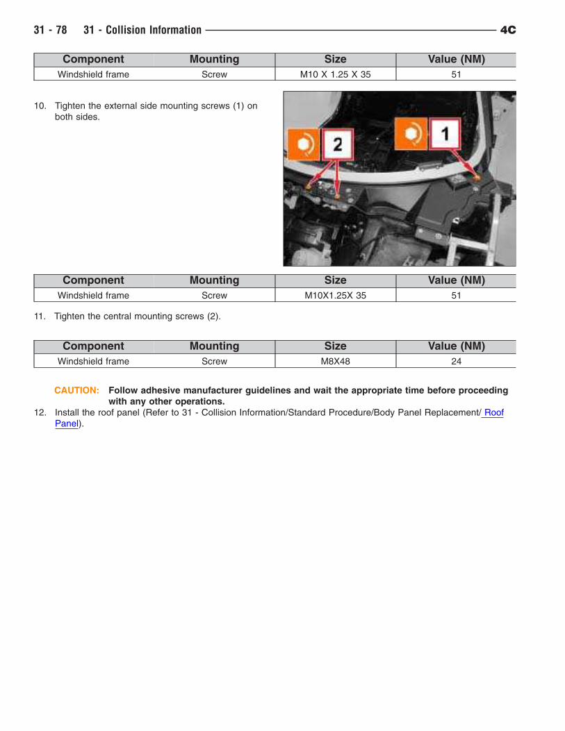
10. Tighten the external side mounting screws (1) on
both sides.
Component Mounting Size Value (NM)
Windshield frame Screw M10X1.25X 35 51
11. Tighten the central mounting screws (2).
Component Mounting Size Value (NM)
Windshield frame Screw M8X48 24
CAUTION: Follow adhesive manufacturer guidelines and wait the appropriate time before proceeding
with any other operations.
12. Install the roof panel (Refer to 31 - Collision Information/Standard Procedure/Body Panel Replacement/ Roof
Panel).
31 - 78 31 - Collision Information 4C
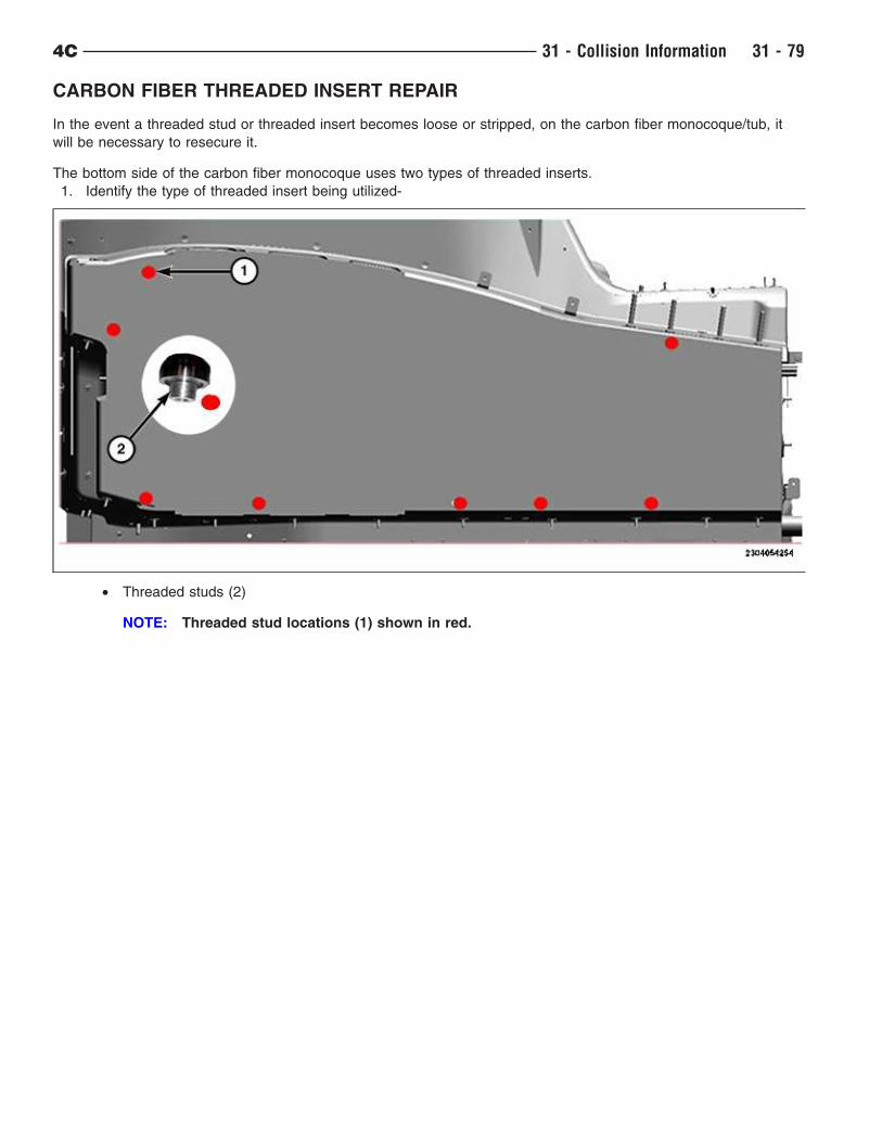
CARBON FIBER THREADED INSERT REPAIR
In the event a threaded stud or threaded insert becomes loose or stripped, on the carbon fiber monocoque/tub, it
will be necessary to resecure it.
The bottom side of the carbon fiber monocoque uses two types of threaded inserts.
1. Identify the type of threaded insert being utilized-
• Threaded studs (2)
NOTE: Threaded stud locations (1) shown in red.
4C 31 - Collision Information 31 - 79
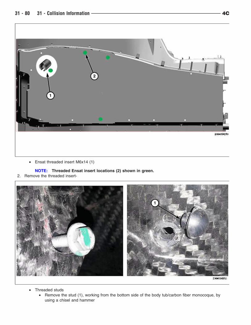
• Ensat threaded insert M6x14 (1)
NOTE: Threaded Ensat insert locations (2) shown in green.
2. Remove the threaded insert-
• Threaded studs
• Remove the stud (1), working from the bottom side of the body tub/carbon fiber monocoque, by
using a chisel and hammer
31 - 80 31 - Collision Information 4C
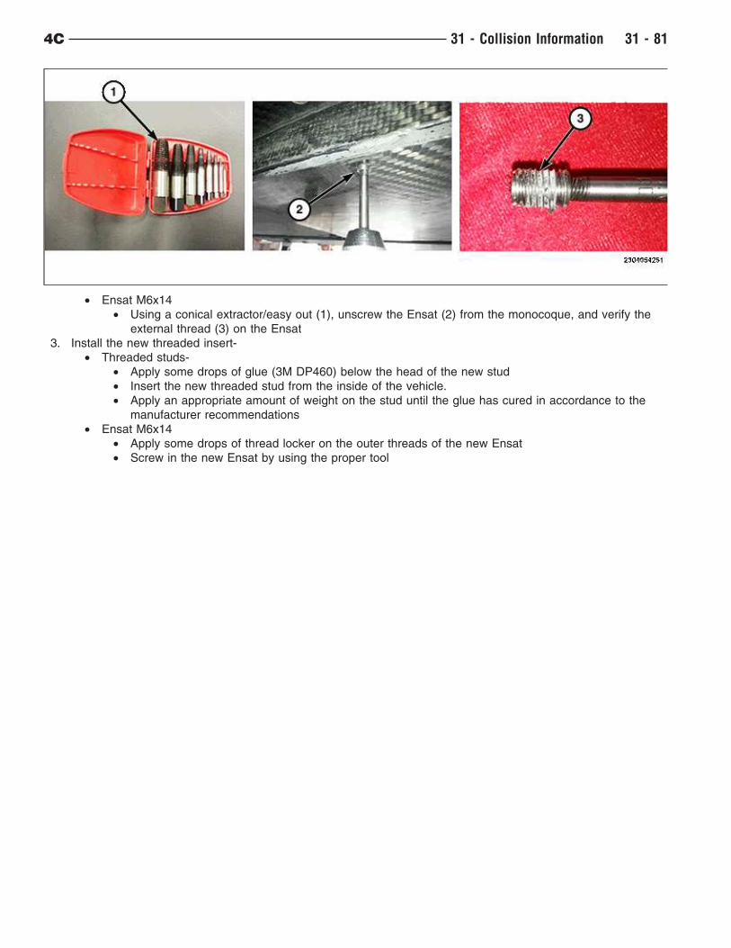
• Ensat M6x14
• Using a conical extractor/easy out (1), unscrew the Ensat (2) from the monocoque, and verify the
external thread (3) on the Ensat
3. Install the new threaded insert-
• Threaded studs-
• Apply some drops of glue (3M DP460) below the head of the new stud
• Insert the new threaded stud from the inside of the vehicle.
• Apply an appropriate amount of weight on the stud until the glue has cured in accordance to the
manufacturer recommendations
• Ensat M6x14
• Apply some drops of thread locker on the outer threads of the new Ensat
• Screw in the new Ensat by using the proper tool
4C 31 - Collision Information 31 - 81
COSMETIC CARBON FIBER REPAIR
Symptom/Condition
• Isolated light to moderate surface conditions (scratches, scuffs, staining, hard water spots, etc.) on carbon
fiber.
NOTE: Thoroughly wash the suspect area before inspection or repair.
Diagnosis
• If the customer describes the symptom, inspect the carbon fiber to determine the extent of the defect. If the
conditions below are found, proceed to the referenced procedure.
Surface Defect Procedure
Significant Scratches Carbon Fiber Cosmetic Correction Procedure
Light Scratches and Scuffs Carbon Fiber Cosmetic Finishing Procedure
Staining and Hard Water spots Carbon Fiber Cosmetic Clay Bar Procedure
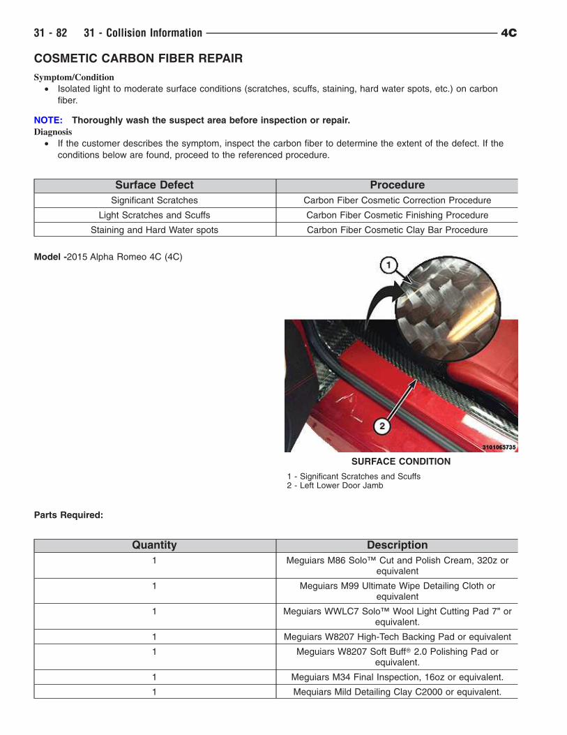
Model -2015 Alpha Romeo 4C (4C)
Parts Required:
Quantity Description
1 Meguiars M86 Solo™ Cut and Polish Cream, 320z orequivalent
1 Meguiars M99 Ultimate Wipe Detailing Cloth orequivalent
1 Meguiars WWLC7 Solo™ Wool Light Cutting Pad 7" orequivalent.
1 Meguiars W8207 High-Tech Backing Pad or equivalent
1 Meguiars W8207 Soft BuffT 2.0 Polishing Pad orequivalent.
1 Meguiars M34 Final Inspection, 16oz or equivalent.
1 Mequiars Mild Detailing Clay C2000 or equivalent.
SURFACE CONDITION
1 - Significant Scratches and Scuffs2 - Left Lower Door Jamb
31 - 82 31 - Collision Information 4C
Quantity Description
1 Meguiars S1525 Mirror GlazeT Unigrit Finishing Paper1500 Grit or equivalent.
1 Meguiars S2015 Unigrit Finishing Paper 2000 Grit orequivalent.
1 Meguiars S2525 Unigrit Finishing Paper 2500 Grit orequivalent.
1 Meguiars W68 Rotary Backing Plate For Soft Buff 2.0Foam Pads or equivalent.
Equipment Required:
Description
Rotary Buffer
Safety Glasses
Extension Cord
NOTE: Measure and document clear resin film thickness before, during and after repair. Only .5 mil of
clear resin removal is permissible for condition repair.
NOTE: Work in a 305mm (12in) x 305mm (12in) at a time. Always work on a cool paint surface, free of
environmental contaminates.
NOTE: Always begin using the least aggressive method based on the condition.
RECOMMENDED CARBON FIBER COSMETIC CLAY BAR PROCEDURE:1. Before removing any defects, wash the effected area with soap and water.
2. Work in a 305 mm (12in) x 305mm (12in) area at a time and apply Meguiars Final Inspection or a detail spray
equivalent to the effected area.
3. Using Mequiars Mild Detailing Clay C2000 or equivalent, work in a unidirectional pattern while the detail spray
applied in Step #2 is still wet.
NOTE: Do not move the clay bar in a circular direction on the panel surface, it will create scratches.
4. If the defect cannot be removed using a clay bar, proceed to the carbon fiber cosmetic finishing procedure.
4C 31 - Collision Information 31 - 83
RECOMMENDED CARBON FIBER COSMETIC CORRECTION PROCEDURE:
NOTE: Always wear appropriate eye, skin and ear protection.
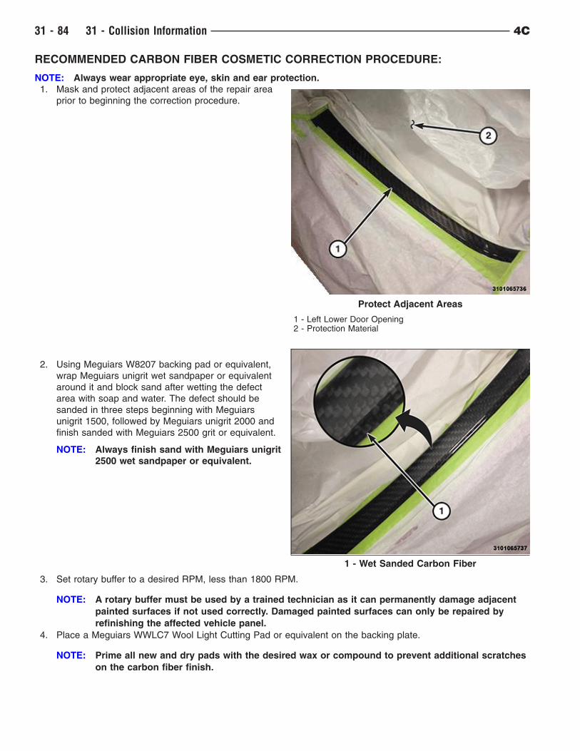
1. Mask and protect adjacent areas of the repair area
prior to beginning the correction procedure.
2. Using Meguiars W8207 backing pad or equivalent,
wrap Meguiars unigrit wet sandpaper or equivalent
around it and block sand after wetting the defect
area with soap and water. The defect should be
sanded in three steps beginning with Meguiars
unigrit 1500, followed by Meguiars unigrit 2000 and
finish sanded with Meguiars 2500 grit or equivalent.
NOTE: Always finish sand with Meguiars unigrit
2500 wet sandpaper or equivalent.
3. Set rotary buffer to a desired RPM, less than 1800 RPM.
NOTE: A rotary buffer must be used by a trained technician as it can permanently damage adjacent
painted surfaces if not used correctly. Damaged painted surfaces can only be repaired by
refinishing the affected vehicle panel.
4. Place a Meguiars WWLC7 Wool Light Cutting Pad or equivalent on the backing plate.
NOTE: Prime all new and dry pads with the desired wax or compound to prevent additional scratches
on the carbon fiber finish.
Protect Adjacent Areas
1 - Left Lower Door Opening2 - Protection Material
1 - Wet Sanded Carbon Fiber
31 - 84 31 - Collision Information 4C
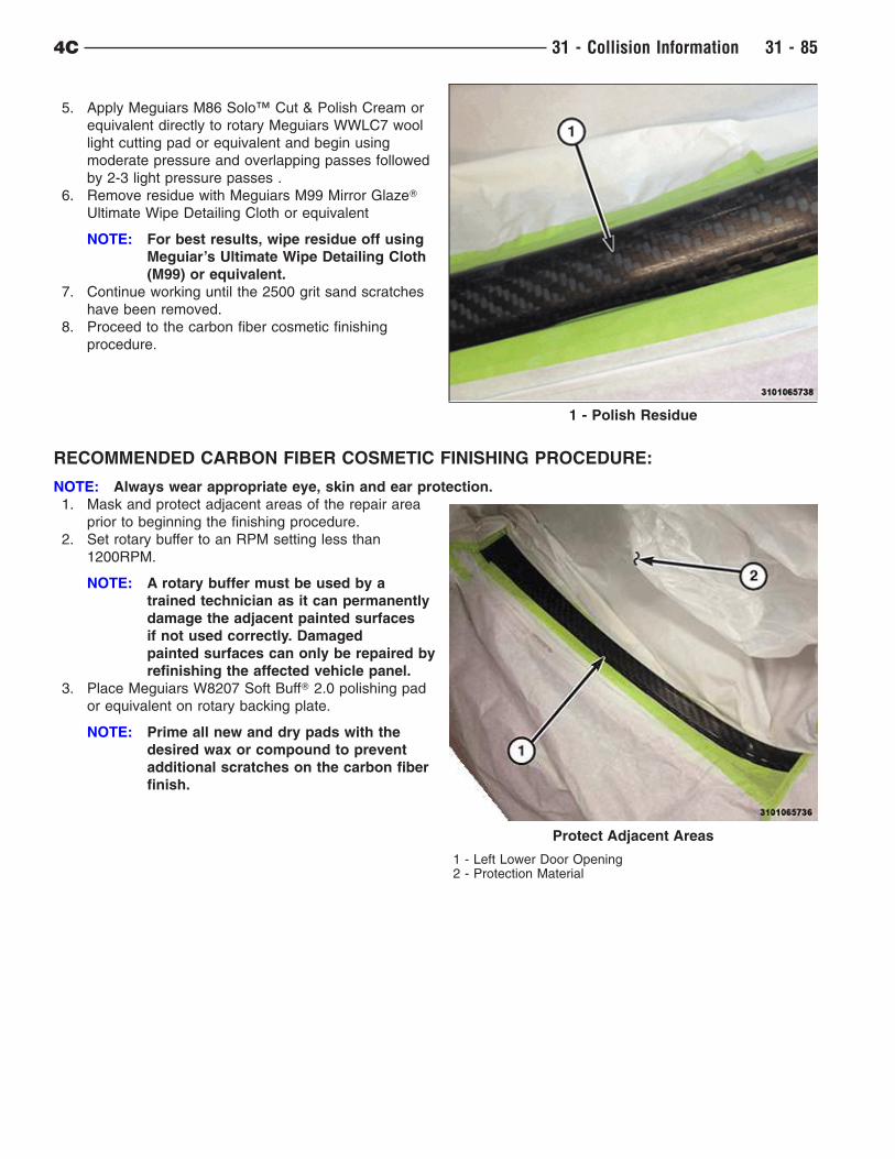
5. Apply Meguiars M86 Solo™ Cut & Polish Cream or
equivalent directly to rotary Meguiars WWLC7 wool
light cutting pad or equivalent and begin using
moderate pressure and overlapping passes followed
by 2-3 light pressure passes .
6. Remove residue with Meguiars M99 Mirror GlazeT
Ultimate Wipe Detailing Cloth or equivalent
NOTE: For best results, wipe residue off using
Meguiar’s Ultimate Wipe Detailing Cloth
(M99) or equivalent.
7. Continue working until the 2500 grit sand scratches
have been removed.
8. Proceed to the carbon fiber cosmetic finishing
procedure.
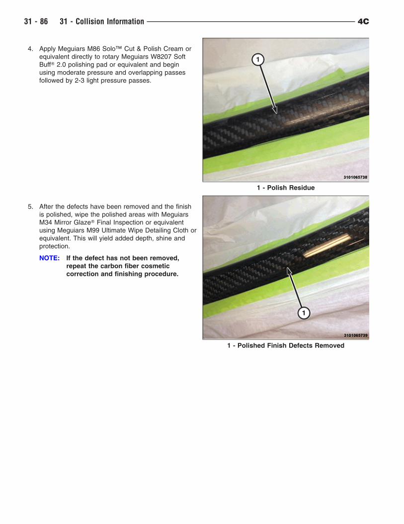
RECOMMENDED CARBON FIBER COSMETIC FINISHING PROCEDURE:
NOTE: Always wear appropriate eye, skin and ear protection.
1. Mask and protect adjacent areas of the repair area
prior to beginning the finishing procedure.
2. Set rotary buffer to an RPM setting less than
1200RPM.
NOTE: A rotary buffer must be used by a
trained technician as it can permanently
damage the adjacent painted surfaces
if not used correctly. Damaged
painted surfaces can only be repaired by
refinishing the affected vehicle panel.
3. Place Meguiars W8207 Soft BuffT 2.0 polishing pad
or equivalent on rotary backing plate.
NOTE: Prime all new and dry pads with the
desired wax or compound to prevent
additional scratches on the carbon fiber
finish.
1 - Polish Residue
Protect Adjacent Areas
1 - Left Lower Door Opening2 - Protection Material
4C 31 - Collision Information 31 - 85
4. Apply Meguiars M86 Solo™ Cut & Polish Cream or
equivalent directly to rotary Meguiars W8207 Soft
BuffT 2.0 polishing pad or equivalent and begin
using moderate pressure and overlapping passes
followed by 2-3 light pressure passes.
5. After the defects have been removed and the finish
is polished, wipe the polished areas with Meguiars
M34 Mirror GlazeT Final Inspection or equivalent
using Meguiars M99 Ultimate Wipe Detailing Cloth or
equivalent. This will yield added depth, shine and
protection.
NOTE: If the defect has not been removed,
repeat the carbon fiber cosmetic
correction and finishing procedure.
1 - Polish Residue
1 - Polished Finish Defects Removed
31 - 86 31 - Collision Information 4C

FINESSE SANDING, BUFFING, AND POLISHING
CAUTION: Do not remove more than 0.5 mils of clearcoat finish when sanding, hand buffing or polishing.
Basecoat paint must retain clearcoat for durability.
CAUTION: If the finish has been finesse sanded in the past, it cannot be repeated. Failure to follow this
caution can result in damage to vehicle finish.
NOTE: Finesse sanding should only be performed by a trained automotive paint technician.
Minor acid etching, orange peel, or smudging in a clearcoat or single-stage finish can be reduced with light finesse
sanding, hand buffing and polishing. Use a Paint Thickness Gauge #PR-ETG-2X or equivalent to determine
clearcoat or single-stage paint thickness before and after the repair.
4C 31 - Collision Information 31 - 87
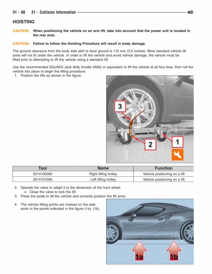
HOISTING
CAUTION: When positioning the vehicle on an arm lift, take into account that the power unit is located in
the rear area.
CAUTION: Failure to follow the Hoisting Procedure will result in body damage.
The ground clearance from the body side skirt to level ground is 110 mm (3.5 inches). Most standard vehicle lift
arms will not fit under the vehicle. In order to lift the vehicle and avoid vehicle damage, the vehicle must be
lifted prior to attempting to lift the vehicle using a standard lift.
Use the recommended GOJAKS Jack dolly (model 4500) or equivalent to lift the vehicle at all four tires, then roll the
vehicle into place to begin the lifting procedure.
1. Position the lifts as shown in the figure.
Tool Name Function
2014100000 Right lifting trolley Vehicle positioning on a lift
2014101000 Left lifting trolley Vehicle positioning on a lift
2. Operate the valve to adapt it to the dimension of the front wheel.
• Close the valve to lock the lift.
3. Press the pedal to lift the vehicle and correctly position the lift arms.
4. The vehicle lifting points are marked on the side
skirts in the points indicated in the figure (1a), (1b).
31 - 88 31 - Collision Information 4C
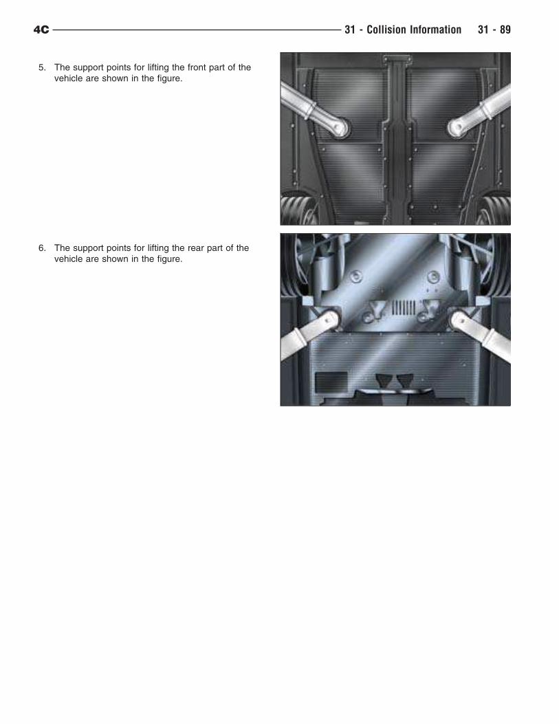
5. The support points for lifting the front part of the
vehicle are shown in the figure.
6. The support points for lifting the rear part of the
vehicle are shown in the figure.
4C 31 - Collision Information 31 - 89
MONOCOQUE DAMAGE DIAGNOSTICS
CARBON FIBER MONOCOQUE REPAIRS:
Due to the technologically advanced design of the carbon fiber monocoque, it is recommended that all repairs be
performed by a qualified technician that specializes in performing carbon fiber structural repairs.
NOTE: Abaris Training is a company that has qualified carbon fiber repair technicians available to perform
on-site monocoque repairs. Abaris can be reached at (775) 827–6568 if this service is required.
They will ask many questions and request photographs to assess the damage and repair cost for
Flying Doctor services.
Background info on Carbon Fiber (Monocoque Construction)
The monocoque for the Alpha 4C is a composite construction which really means a combination of “plastic” and
reinforcing fibers. In this case the reinforcing fibers come in the form of a woven cloth made from carbon fiber. The
cloth is impregnated with a heat curing adhesive before manufacturing, called pre-preg. The carbon fiber cloth is cut
into pieces which are then laid into molds in a very specific order and fashion ensuring that the orientation of the
cloth weave is precise. This is referred to as the “lay up” process. When the “lay up” is complete, the various
components are subjected to vacuum (negative pressure) and heated in a device called an autoclave which cures
the adhesives and draws out any air from within the plies. The end result is an extremely strong structure which
is light in weight.
Compared with traditional unibody construction, and the metals utilized, damage analysis is quite different. Instead
of dents, kinks, or buckles, the damage will be either a compromise of the layered construction, or in an extreme
case complete tearing of the structure. Determining whether damage exists, and to what extent, requires several
different types of equipment including ultrasound imaging (ultrasonic testing) and infra-red cameras (Thermographic
imagery) – tools which are not commonly found in the collision repair environment. For composite based structures
there are two levels of damage analysis –
• The first is for determining if any repairs may be necessary.
• Then secondarily in the repair process is to make a repair plan for the structure.
In the basic level of damage analysis knowing the key areas which would be most likely damaged in a collision
event and having a couple of very basic “tools” is adequate.
Crash testing data
There are four primary impact damage modes expected to the monocoque:
• Frontal impact
• Rear impact
• Side impact
• Underbody impact (such as from an off-road excursion)
In the real world it is usually not always so cut and dry and damage may be caused by a combination of these four
primary impact damage modes. Crash modeling software has been utilized to predict the most likely locations of
possible monocoque damage in both front and rear impact events. These locations are referred to as “hot-
spots” and the most likely locations where the structure may be damaged but a thorough visual inspection is always
necessary.
The front and rear crash modeling of the Alfa 4C was performed at 48 km/h (30 mph) and is based upon impact
with a flat rigid barrier. Real world impacts typically involve other vehicles which are “softer” than the barrier and the
impacts are also generally not perfectly “square”. While the modeled impacts may be different from a real world
occurrence, they provide robust information which should be used during damage analysis. One key point
about these modeled events is that they are severe enough to completely crush the front and rear subframes – the
crushing of the subframes absorbs energy and protects the occupants and monocoque.
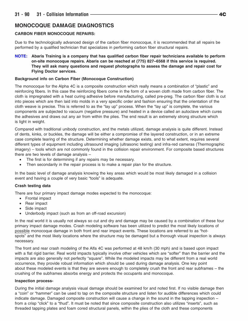
Inspection process-
During the initial damage analysis visual damage should be examined for and noted first. If no visible damage then
a “coin” or “hammer” can be used to tap on the composite structure and listen for audible differences which could
indicate damage. Damaged composite construction will cause a change in the sound in the tapping inspection –
from a crisp “click” to a “thud”. It must be noted that since composite construction also utilizes “inserts”, such as
threaded tapping plates and foam cored structural panels, within the plies of the cloth and these components
31 - 90 31 - Collision Information 4C
will also cause an audible difference but not the “thud” of damaged composite layers.
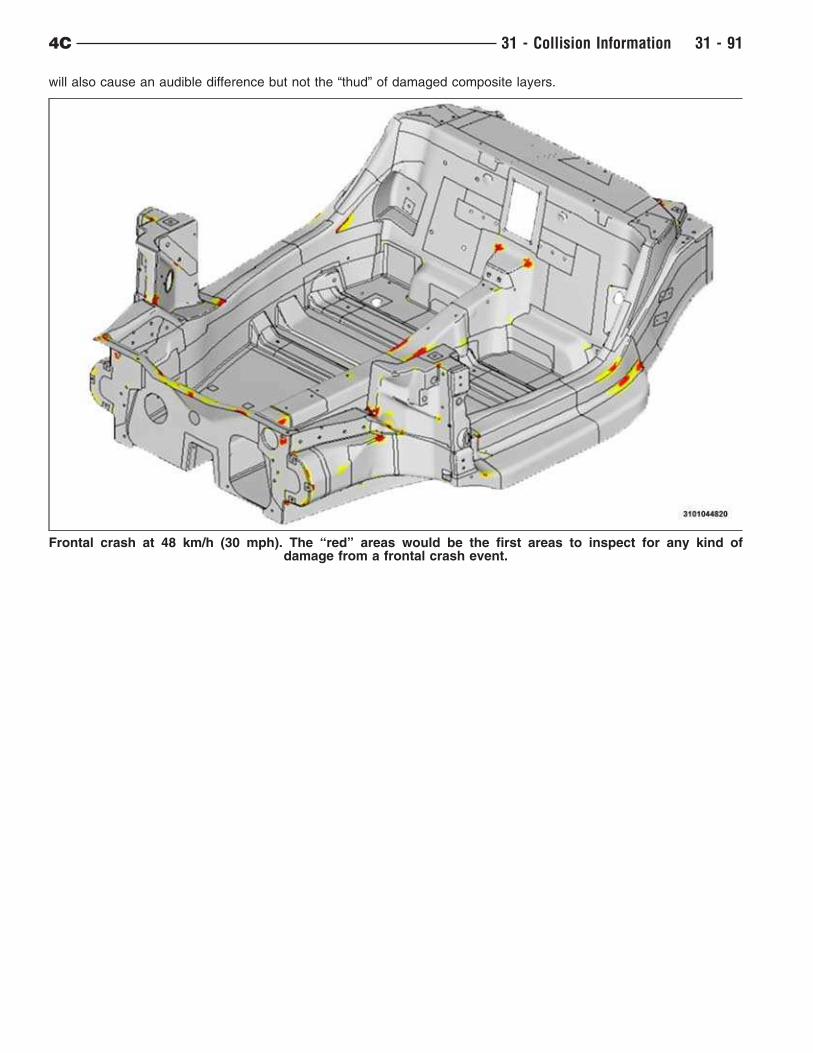
Frontal crash at 48 km/h (30 mph). The “red” areas would be the first areas to inspect for any kind ofdamage from a frontal crash event.
4C 31 - Collision Information 31 - 91
Side impact events will typically involve three key areas:
• Door hinge pillar
• Sill (rocker panel)
• B-pillar
Underbody impact from something like an off-road event, require a complete visual inspection with emphasis on the
front suspension mounting locations and the monocoque floor. While the suspension is designed to crush before
translating impact loads into the suspension mounting area, component stack-up during crush could circumvent this
and transfer load. The underbody floor is thinner and may be damaged by sharp or pointed objects such as from
rocks and other road debris.
Post inspection/Flying doctors/Advanced testing equipment-
Once the inspection of the monocoque is complete the damage analysis process should continue with an estimation
of overall vehicle damage. If monocoque damage exists then Abaris Training should be contacted. They will ask
many questions and request photographs of the damage for estimation of the likely repair cost by a Flying Doctor.
With the estimation of monocoque repair costs the damage estimate can be completed. It should be noted due
to the very high strength of the carbon-fiber monocoque finding “no damage” is not unexpected in vehicles that
appear normally repairable based on the estimator’s experience and judgment. If there are any questions or
concerns then Abaris Training should be contacted to discuss.
The more exotic tools used in damage analysis such as ultrasound and thermal imaging cameras, which come
primarily from the aerospace industry, allow “visualization” of the compromised structure but are not required in the
initial damage analysis phase. These tools are however very helpful for the Flying Doctor to confirm both the total
repair necessary and to illustrate that a repair has been completed.
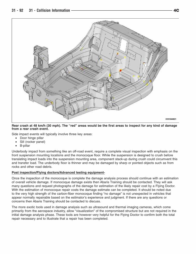
Rear crash at 48 km/h (30 mph). The “red” areas would be the first areas to inspect for any kind of damagefrom a rear crash event.
31 - 92 31 - Collision Information 4C
REAR RAIL EXTENSION
NOTE: After fitting the NEW side member, carry out the assembly measurements and possible correction
interventions) within 60 minutes after applying the adhesive product (Refer to 31 - Collision
Information/Specifications/Frame Dimensions).
NOTE: The operations below must be carried out on the vehicle, after removing all electrical and/or
mechanical parts that may interfere with the removal and refitting operations from the area
surrounding the component.
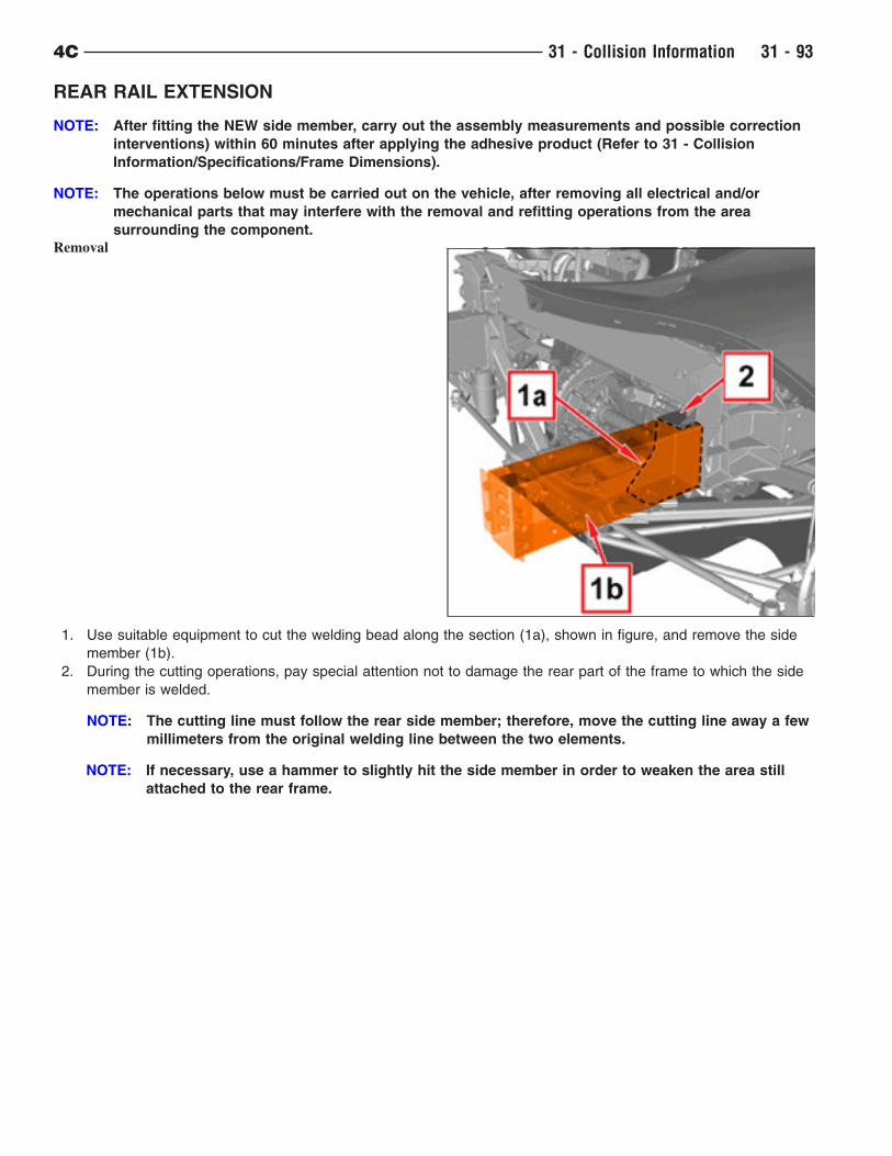
Removal
1. Use suitable equipment to cut the welding bead along the section (1a), shown in figure, and remove the side
member (1b).
2. During the cutting operations, pay special attention not to damage the rear part of the frame to which the side
member is welded.
NOTE: The cutting line must follow the rear side member; therefore, move the cutting line away a few
millimeters from the original welding line between the two elements.
NOTE: If necessary, use a hammer to slightly hit the side member in order to weaken the area still
attached to the rear frame.
4C 31 - Collision Information 31 - 93
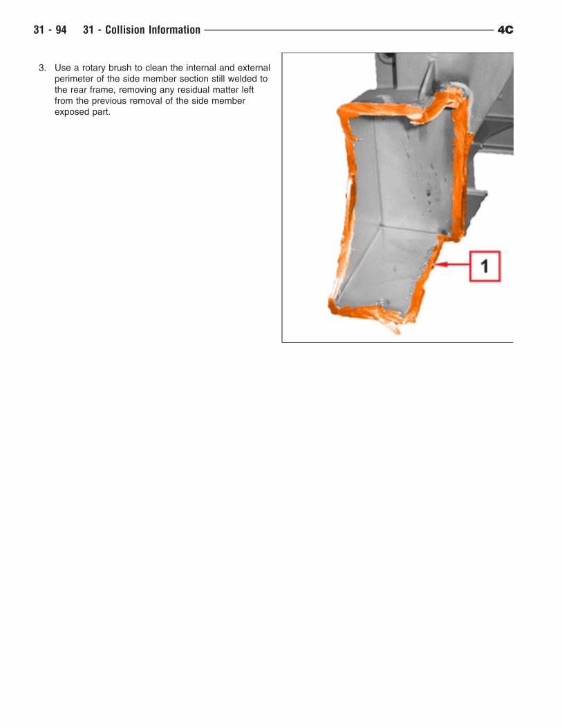
3. Use a rotary brush to clean the internal and external
perimeter of the side member section still welded to
the rear frame, removing any residual matter left
from the previous removal of the side member
exposed part.
31 - 94 31 - Collision Information 4C
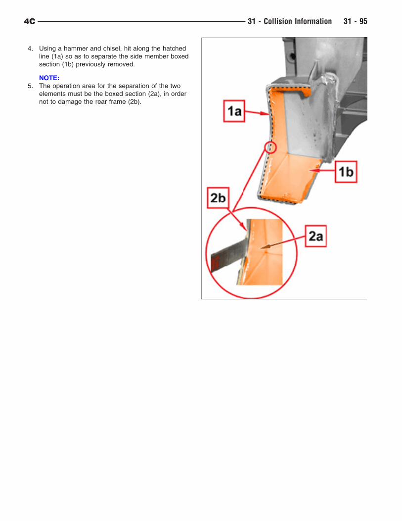
4. Using a hammer and chisel, hit along the hatched
line (1a) so as to separate the side member boxed
section (1b) previously removed.
NOTE:
5. The operation area for the separation of the two
elements must be the boxed section (2a), in order
not to damage the rear frame (2b).
4C 31 - Collision Information 31 - 95
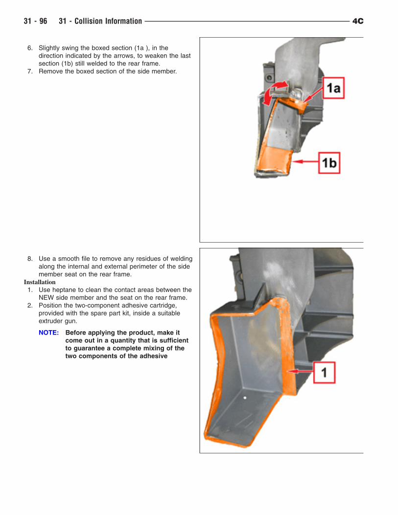
6. Slightly swing the boxed section (1a ), in the
direction indicated by the arrows, to weaken the last
section (1b) still welded to the rear frame.
7. Remove the boxed section of the side member.
8. Use a smooth file to remove any residues of welding
along the internal and external perimeter of the side
member seat on the rear frame.
Installation
1. Use heptane to clean the contact areas between the
NEW side member and the seat on the rear frame.
2. Position the two-component adhesive cartridge,
provided with the spare part kit, inside a suitable
extruder gun.
NOTE: Before applying the product, make it
come out in a quantity that is sufficient
to guarantee a complete mixing of the
two components of the adhesive
31 - 96 31 - Collision Information 4C
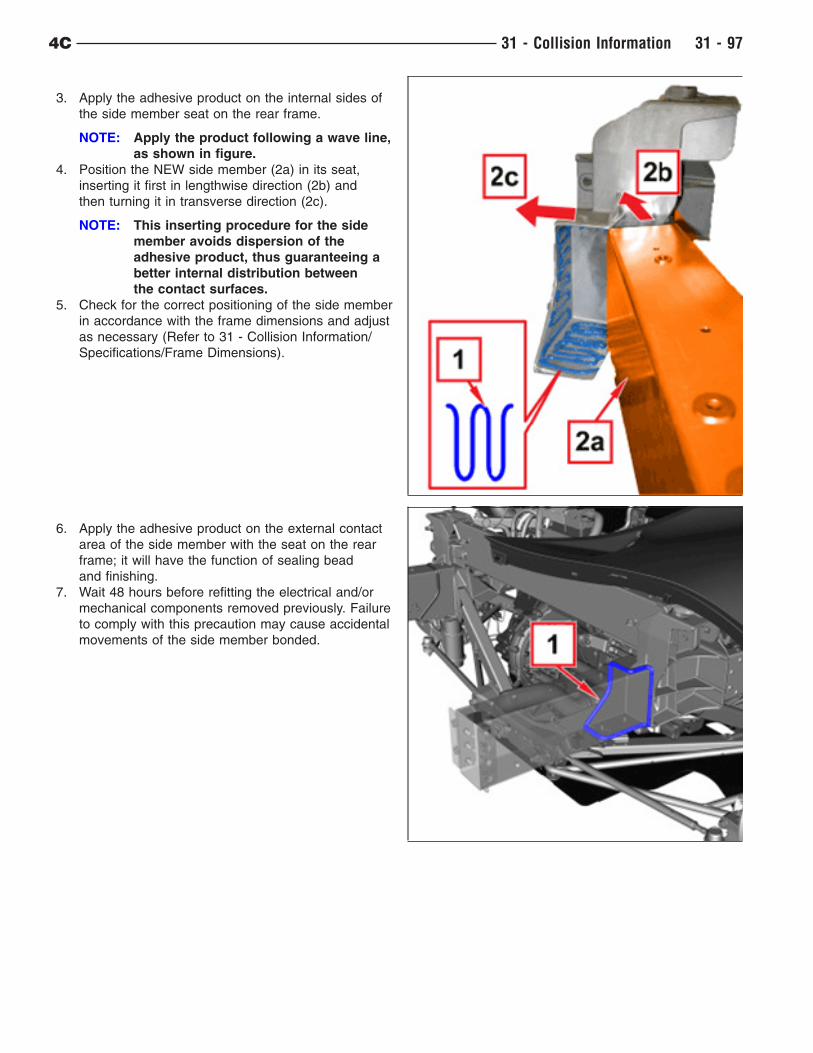
3. Apply the adhesive product on the internal sides of
the side member seat on the rear frame.
NOTE: Apply the product following a wave line,
as shown in figure.
4. Position the NEW side member (2a) in its seat,
inserting it first in lengthwise direction (2b) and
then turning it in transverse direction (2c).
NOTE: This inserting procedure for the side
member avoids dispersion of the
adhesive product, thus guaranteeing a
better internal distribution between
the contact surfaces.
5. Check for the correct positioning of the side member
in accordance with the frame dimensions and adjust
as necessary (Refer to 31 - Collision Information/
Specifications/Frame Dimensions).
6. Apply the adhesive product on the external contact
area of the side member with the seat on the rear
frame; it will have the function of sealing bead
and finishing.
7. Wait 48 hours before refitting the electrical and/or
mechanical components removed previously. Failure
to comply with this precaution may cause accidental
movements of the side member bonded.
4C 31 - Collision Information 31 - 97
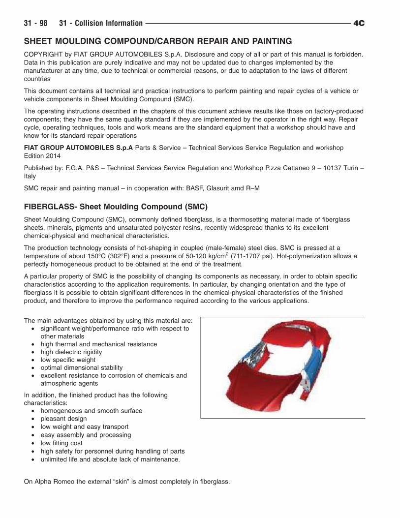
SHEET MOULDING COMPOUND/CARBON REPAIR AND PAINTING
COPYRIGHT by FIAT GROUP AUTOMOBILES S.p.A. Disclosure and copy of all or part of this manual is forbidden.
Data in this publication are purely indicative and may not be updated due to changes implemented by the
manufacturer at any time, due to technical or commercial reasons, or due to adaptation to the laws of different
countries
This document contains all technical and practical instructions to perform painting and repair cycles of a vehicle or
vehicle components in Sheet Moulding Compound (SMC).
The operating instructions described in the chapters of this document achieve results like those on factory-produced
components; they have the same quality standard if they are implemented by the operator in the right way. Repair
cycle, operating techniques, tools and work means are the standard equipment that a workshop should have and
know for its standard repair operations
FIAT GROUP AUTOMOBILES S.p.A Parts & Service – Technical Services Service Regulation and workshop
Edition 2014
Published by: F.G.A. P&S – Technical Services Service Regulation and Workshop P.zza Cattaneo 9 – 10137 Turin –
Italy
SMC repair and painting manual – in cooperation with: BASF, Glasurit amd R–M
FIBERGLASS- Sheet Moulding Compound (SMC)
Sheet Moulding Compound (SMC), commonly defined fiberglass, is a thermosetting material made of fiberglass
sheets, minerals, pigments and unsaturated polyester resins, recently widespread thanks to its excellent
chemical-physical and mechanical characteristics.
The production technology consists of hot-shaping in coupled (male-female) steel dies. SMC is pressed at a
temperature of about 150°C (302°F) and a pressure of 50-120 kg/cm2 (711-1707 psi). Hot-polymerization allows a
perfectly homogeneous product to be obtained at the end of the treatment.
A particular property of SMC is the possibility of changing its components as necessary, in order to obtain specific
characteristics according to the application requirements. In particular, by changing orientation and the type of
fiberglass it is possible to obtain significant differences in the chemical-physical characteristics of the finished
product, and therefore to improve the performance required according to the various applications.
The main advantages obtained by using this material are:
• significant weight/performance ratio with respect to
other materials
• high thermal and mechanical resistance
• high dielectric rigidity
• low specific weight
• optimal dimensional stability
• excellent resistance to corrosion of chemicals and
atmospheric agents
In addition, the finished product has the following
characteristics:
• homogeneous and smooth surface
• pleasant design
• low weight and easy transport
• easy assembly and processing
• low fitting cost
• high safety for personnel during handling of parts
• unlimited life and absolute lack of maintenance.
On Alpha Romeo the external “skin” is almost completely in fiberglass.
31 - 98 31 - Collision Information 4C
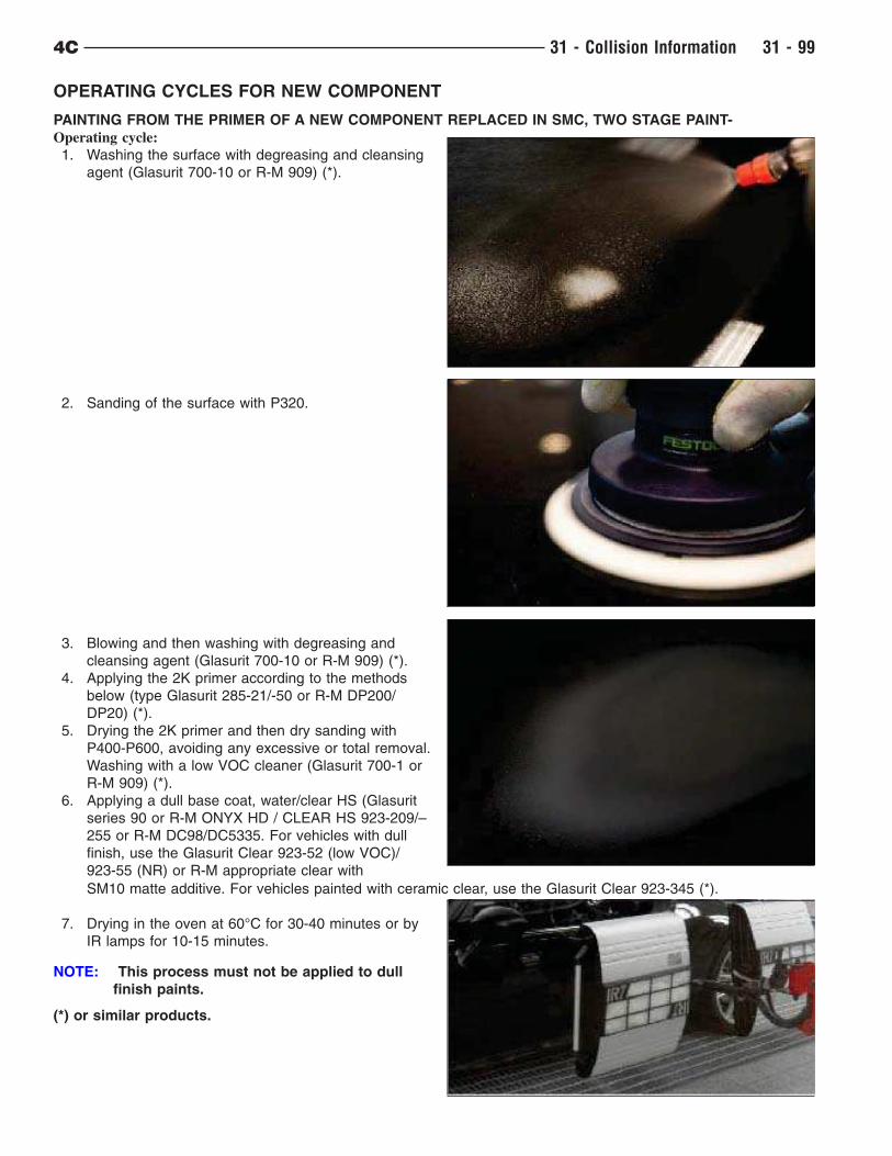
OPERATING CYCLES FOR NEW COMPONENT
PAINTING FROM THE PRIMER OF A NEW COMPONENT REPLACED IN SMC, TWO STAGE PAINT-
Operating cycle:
1. Washing the surface with degreasing and cleansing
agent (Glasurit 700-10 or R-M 909) (*).
2. Sanding of the surface with P320.
3. Blowing and then washing with degreasing and
cleansing agent (Glasurit 700-10 or R-M 909) (*).
4. Applying the 2K primer according to the methods
below (type Glasurit 285-21/-50 or R-M DP200/
DP20) (*).
5. Drying the 2K primer and then dry sanding with
P400-P600, avoiding any excessive or total removal.
Washing with a low VOC cleaner (Glasurit 700-1 or
R-M 909) (*).
6. Applying a dull base coat, water/clear HS (Glasurit
series 90 or R-M ONYX HD / CLEAR HS 923-209/–
255 or R-M DC98/DC5335. For vehicles with dull
finish, use the Glasurit Clear 923-52 (low VOC)/
923-55 (NR) or R-M appropriate clear with
SM10 matte additive. For vehicles painted with ceramic clear, use the Glasurit Clear 923-345 (*).
7. Drying in the oven at 60°C for 30-40 minutes or by
IR lamps for 10-15 minutes.
NOTE: This process must not be applied to dull
finish paints.
(*) or similar products.
4C 31 - Collision Information 31 - 99
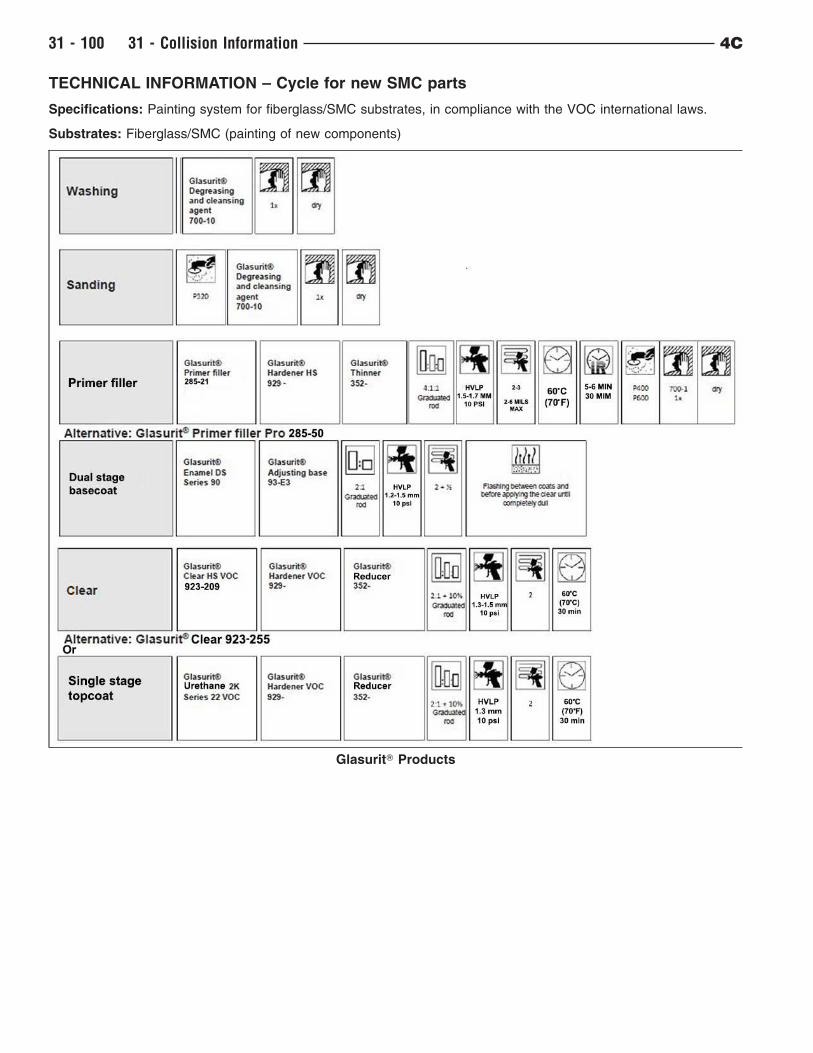
TECHNICAL INFORMATION – Cycle for new SMC parts
Specifications: Painting system for fiberglass/SMC substrates, in compliance with the VOC international laws.
Substrates: Fiberglass/SMC (painting of new components)
GlasuritT Products
31 - 100 31 - Collision Information 4C
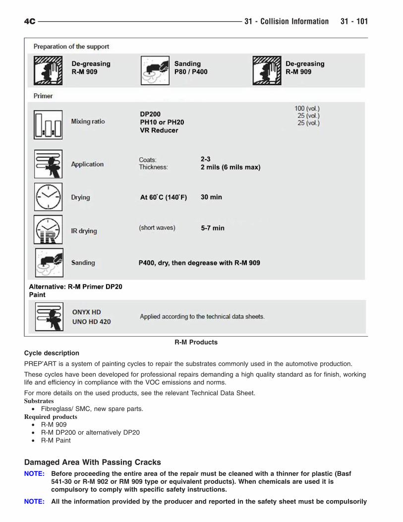
Cycle description
PREP’ART is a system of painting cycles to repair the substrates commonly used in the automotive production.
These cycles have been developed for professional repairs demanding a high quality standard as for finish, working
life and efficiency in compliance with the VOC emissions and norms.
For more details on the used products, see the relevant Technical Data Sheet.
Substrates
• Fibreglass/ SMC, new spare parts.
Required products
• R-M 909
• R-M DP200 or alternatively DP20
• R-M Paint
Damaged Area With Passing Cracks
NOTE: Before proceeding the entire area of the repair must be cleaned with a thinner for plastic (Basf
541-30 or R-M 902 or RM 909 type or equivalent products). When chemicals are used it is
compulsory to comply with specific safety instructions.
NOTE: All the information provided by the producer and reported in the safety sheet must be compulsorily
R-M Products
4C 31 - Collision Information 31 - 101
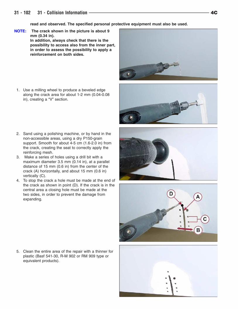
read and observed. The specified personal protective equipment must also be used.
NOTE: The crack shown in the picture is about 9
mm (0.34 in).
In addition, always check that there is the
possibility to access also from the inner part,
in order to assess the possibility to apply a
reinforcement on both sides.
1. Use a milling wheel to produce a beveled edge
along the crack area for about 1-2 mm (0.04-0.08
in), creating a “V” section.
2. Sand using a polishing machine, or by hand in the
non-accessible areas, using a dry P150-grain
support. Smooth for about 4-5 cm (1.6-2.0 in) from
the crack, creating the seat to correctly apply the
reinforcing mesh.
3. Make a series of holes using a drill bit with a
maximum diameter 3.5 mm (0.14 in), at a parallel
distance of 15 mm (0.6 in) from the center of the
crack (A) horizontally, and about 15 mm (0.6 in)
vertically (C).
4. To stop the crack a hole must be made at the end of
the crack as shown in point (D). If the crack is in the
central area a closing hole must be made at the
two sides, in order to prevent the damage from
expanding.
5. Clean the entire area of the repair with a thinner for
plastic (Basf 541-30, R-M 902 or RM 909 type or
equivalent products).
31 - 102 31 - Collision Information 4C
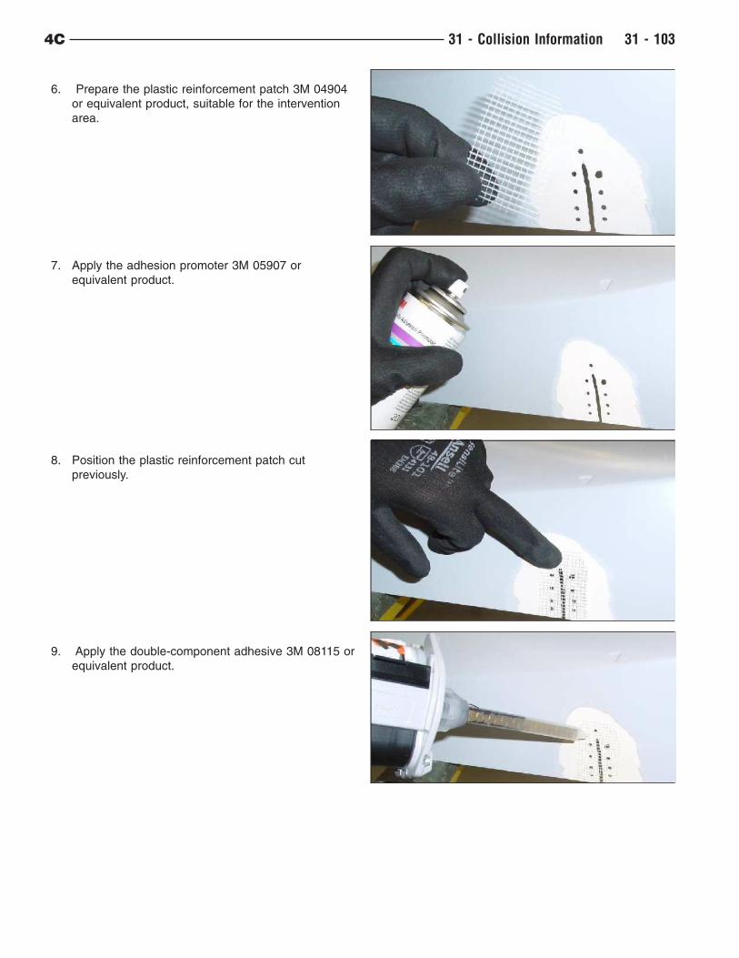
6. Prepare the plastic reinforcement patch 3M 04904
or equivalent product, suitable for the intervention
area.
7. Apply the adhesion promoter 3M 05907 or
equivalent product.
8. Position the plastic reinforcement patch cut
previously.
9. Apply the double-component adhesive 3M 08115 or
equivalent product.
4C 31 - Collision Information 31 - 103
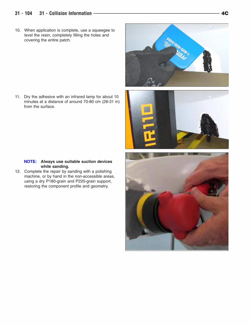
10. When application is complete, use a squeegee to
level the resin, completely filling the holes and
covering the entire patch.
11. Dry the adhesive with an infrared lamp for about 10
minutes at a distance of around 70-80 cm (28-31 in)
from the surface.
NOTE: Always use suitable suction devices
while sanding.
12. Complete the repair by sanding with a polishing
machine, or by hand in the non-accessible areas,
using a dry P180-grain and P220-grain support,
restoring the component profile and geometry.
31 - 104 31 - Collision Information 4C
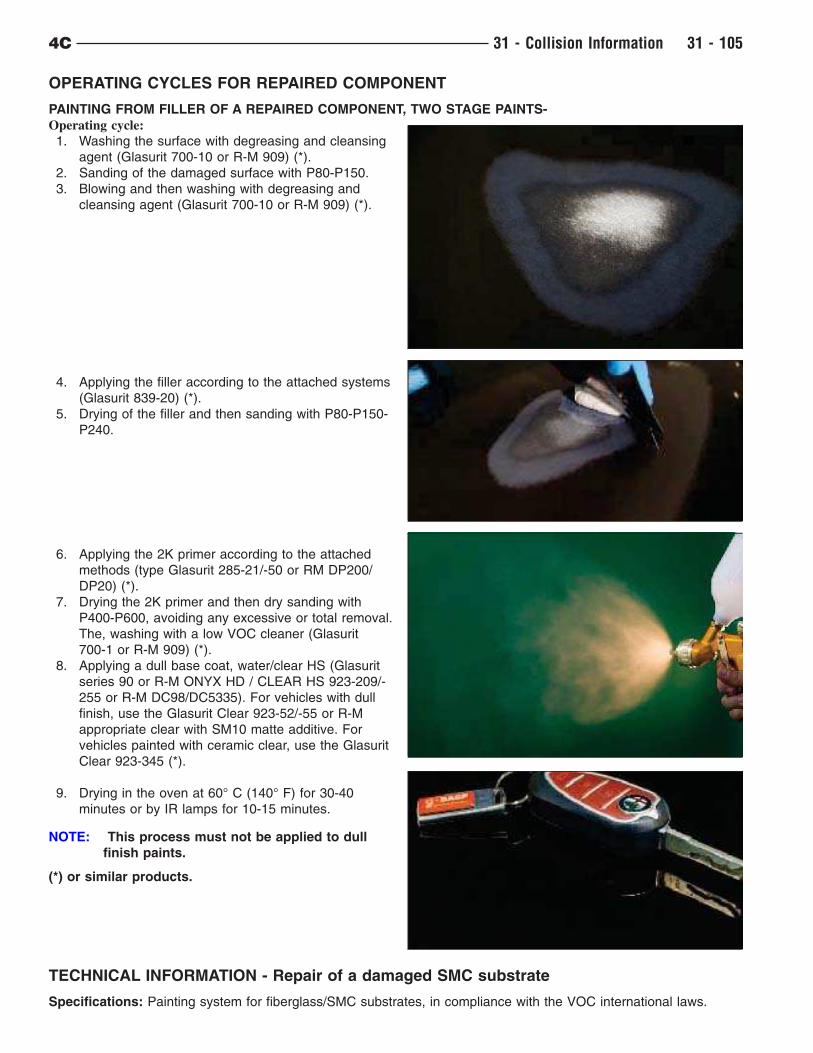
OPERATING CYCLES FOR REPAIRED COMPONENT
PAINTING FROM FILLER OF A REPAIRED COMPONENT, TWO STAGE PAINTS-
Operating cycle:
1. Washing the surface with degreasing and cleansing
agent (Glasurit 700-10 or R-M 909) (*).
2. Sanding of the damaged surface with P80-P150.
3. Blowing and then washing with degreasing and
cleansing agent (Glasurit 700-10 or R-M 909) (*).
4. Applying the filler according to the attached systems
(Glasurit 839-20) (*).
5. Drying of the filler and then sanding with P80-P150-
P240.
6. Applying the 2K primer according to the attached
methods (type Glasurit 285-21/-50 or RM DP200/
DP20) (*).
7. Drying the 2K primer and then dry sanding with
P400-P600, avoiding any excessive or total removal.
The, washing with a low VOC cleaner (Glasurit
700-1 or R-M 909) (*).
8. Applying a dull base coat, water/clear HS (Glasurit
series 90 or R-M ONYX HD / CLEAR HS 923-209/-
255 or R-M DC98/DC5335). For vehicles with dull
finish, use the Glasurit Clear 923-52/-55 or R-M
appropriate clear with SM10 matte additive. For
vehicles painted with ceramic clear, use the Glasurit
Clear 923-345 (*).
9. Drying in the oven at 60° C (140° F) for 30-40
minutes or by IR lamps for 10-15 minutes.
NOTE: This process must not be applied to dull
finish paints.
(*) or similar products.
TECHNICAL INFORMATION - Repair of a damaged SMC substrate
Specifications: Painting system for fiberglass/SMC substrates, in compliance with the VOC international laws.
4C 31 - Collision Information 31 - 105
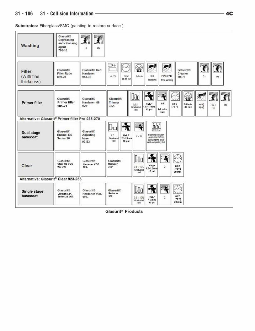
Substrates: Fiberglass/SMC (painting to restore surface )
GlasuritT Products
31 - 106 31 - Collision Information 4C
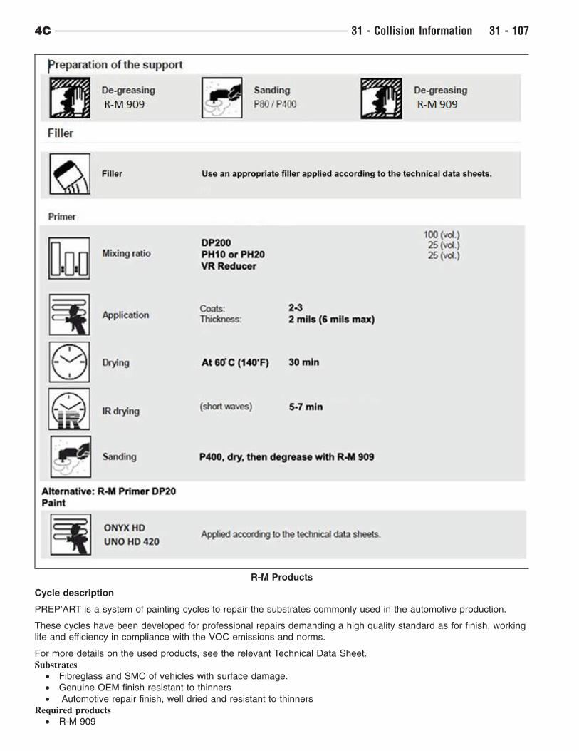
Cycle description
PREP’ART is a system of painting cycles to repair the substrates commonly used in the automotive production.
These cycles have been developed for professional repairs demanding a high quality standard as for finish, working
life and efficiency in compliance with the VOC emissions and norms.
For more details on the used products, see the relevant Technical Data Sheet.
Substrates
• Fibreglass and SMC of vehicles with surface damage.
• Genuine OEM finish resistant to thinners
• Automotive repair finish, well dried and resistant to thinners
Required products
• R-M 909
R-M Products
4C 31 - Collision Information 31 - 107
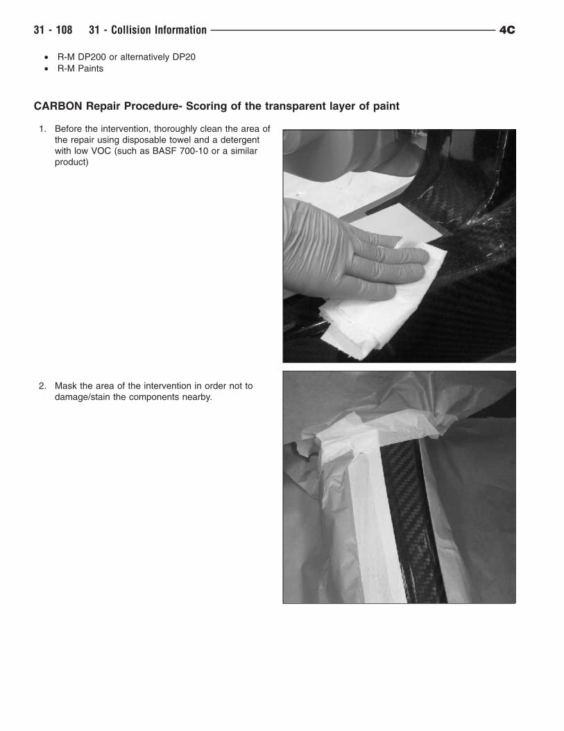
• R-M DP200 or alternatively DP20
• R-M Paints
CARBON Repair Procedure- Scoring of the transparent layer of paint
1. Before the intervention, thoroughly clean the area of
the repair using disposable towel and a detergent
with low VOC (such as BASF 700-10 or a similar
product)
2. Mask the area of the intervention in order not to
damage/stain the components nearby.
31 - 108 31 - Collision Information 4C
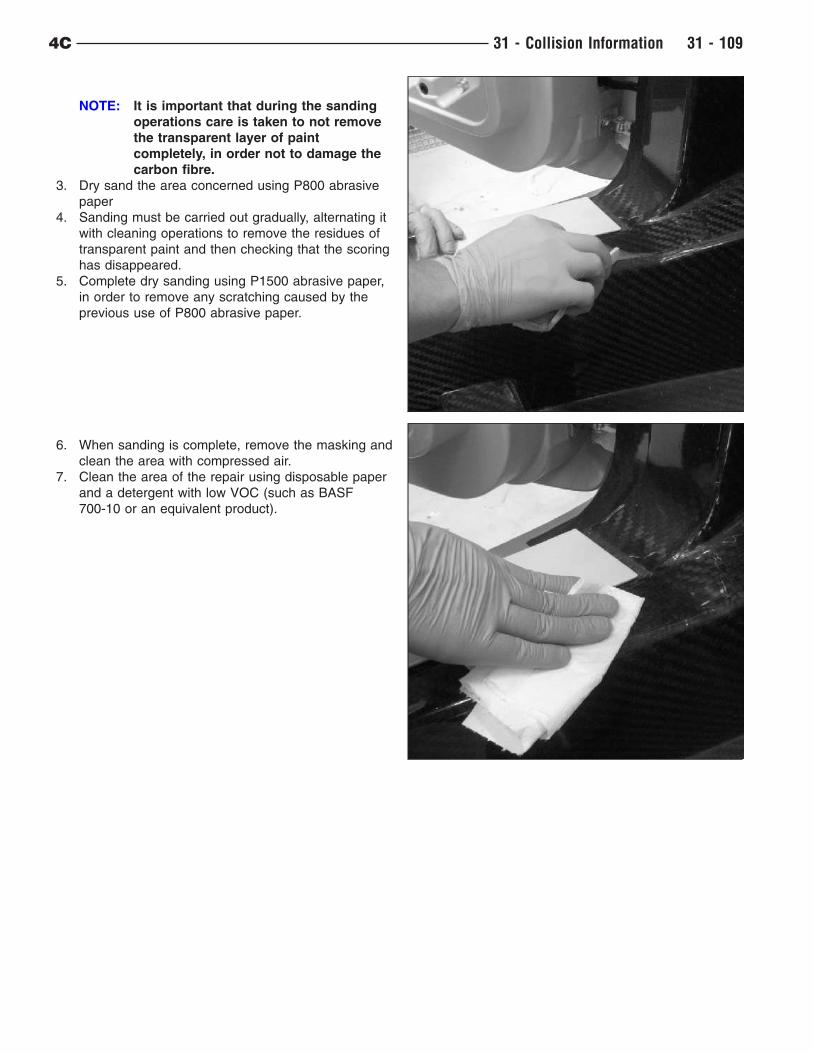
NOTE: It is important that during the sanding
operations care is taken to not remove
the transparent layer of paint
completely, in order not to damage the
carbon fibre.
3. Dry sand the area concerned using P800 abrasive
paper
4. Sanding must be carried out gradually, alternating it
with cleaning operations to remove the residues of
transparent paint and then checking that the scoring
has disappeared.
5. Complete dry sanding using P1500 abrasive paper,
in order to remove any scratching caused by the
previous use of P800 abrasive paper.
6. When sanding is complete, remove the masking and
clean the area with compressed air.
7. Clean the area of the repair using disposable paper
and a detergent with low VOC (such as BASF
700-10 or an equivalent product).
4C 31 - Collision Information 31 - 109
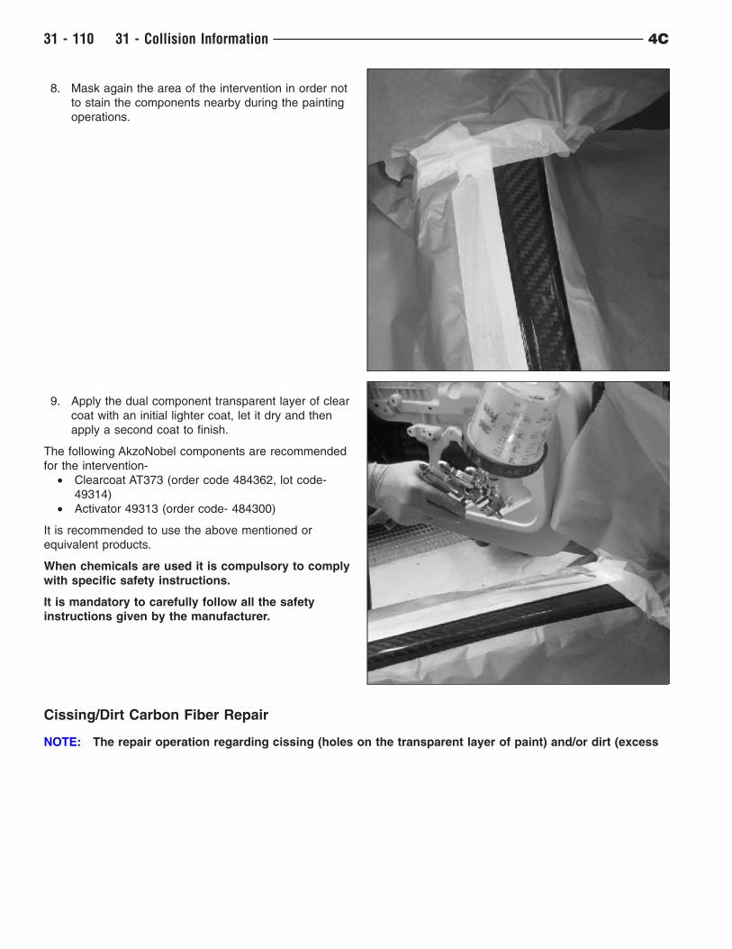
8. Mask again the area of the intervention in order not
to stain the components nearby during the painting
operations.
9. Apply the dual component transparent layer of clear
coat with an initial lighter coat, let it dry and then
apply a second coat to finish.
The following AkzoNobel components are recommended
for the intervention-
• Clearcoat AT373 (order code 484362, lot code-
49314)
• Activator 49313 (order code- 484300)
It is recommended to use the above mentioned or
equivalent products.
When chemicals are used it is compulsory to comply
with specific safety instructions.
It is mandatory to carefully follow all the safety
instructions given by the manufacturer.
Cissing/Dirt Carbon Fiber Repair
NOTE: The repair operation regarding cissing (holes on the transparent layer of paint) and/or dirt (excess
31 - 110 31 - Collision Information 4C
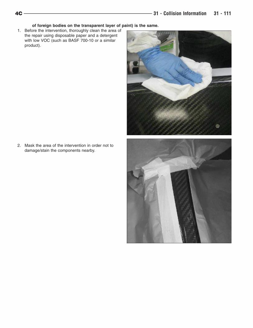
of foreign bodies on the transparent layer of paint) is the same.
1. Before the intervention, thoroughly clean the area of
the repair using disposable paper and a detergent
with low VOC (such as BASF 700-10 or a similar
product).
2. Mask the area of the intervention in order not to
damage/stain the components nearby.
4C 31 - Collision Information 31 - 111
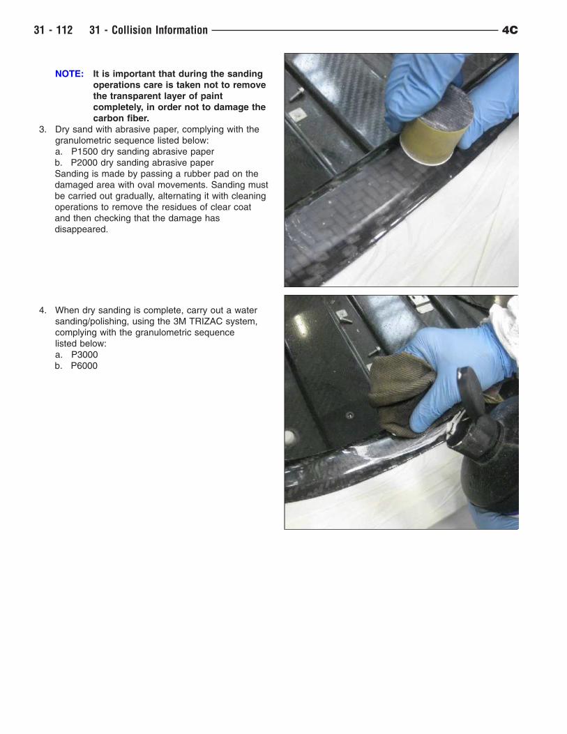
NOTE: It is important that during the sanding
operations care is taken not to remove
the transparent layer of paint
completely, in order not to damage the
carbon fiber.
3. Dry sand with abrasive paper, complying with the
granulometric sequence listed below:
a. P1500 dry sanding abrasive paper
b. P2000 dry sanding abrasive paper
Sanding is made by passing a rubber pad on the
damaged area with oval movements. Sanding must
be carried out gradually, alternating it with cleaning
operations to remove the residues of clear coat
and then checking that the damage has
disappeared.
4. When dry sanding is complete, carry out a water
sanding/polishing, using the 3M TRIZAC system,
complying with the granulometric sequence
listed below:
a. P3000
b. P6000
31 - 112 31 - Collision Information 4C
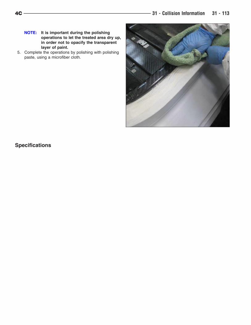
NOTE: It is important during the polishing
operations to let the treated area dry up,
in order not to opacify the transparent
layer of paint.
5. Complete the operations by polishing with polishing
paste, using a microfiber cloth.
Specifications
4C 31 - Collision Information 31 - 113
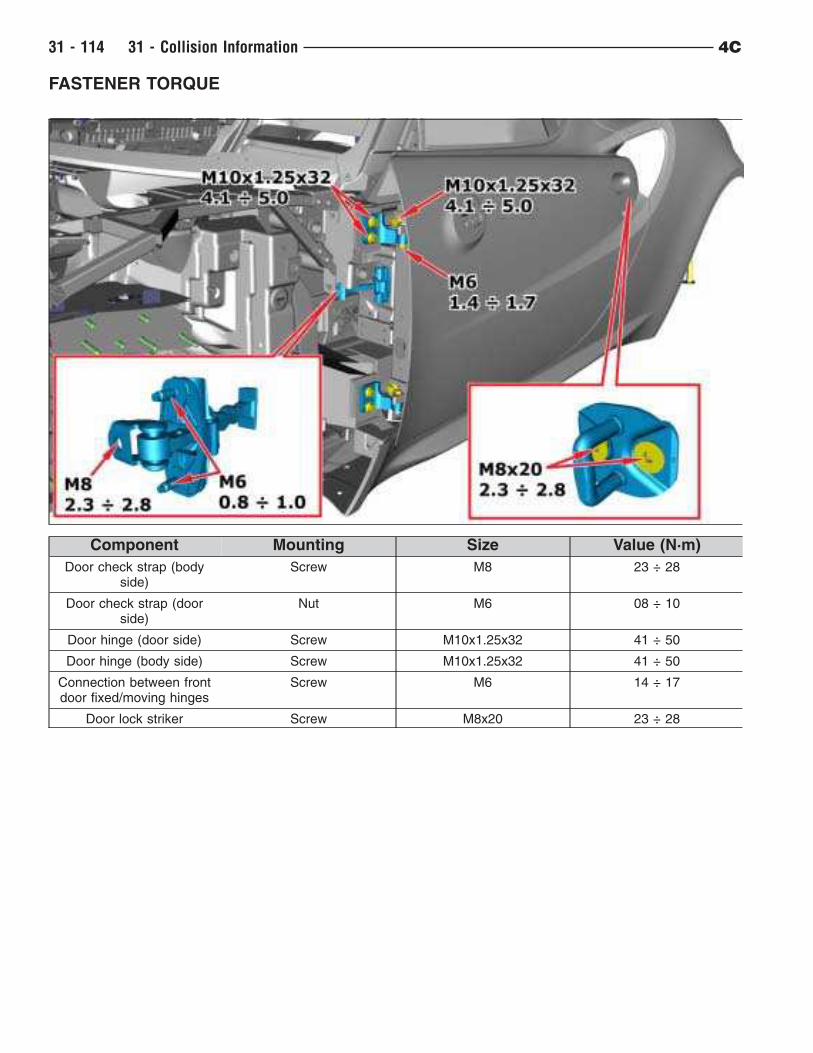
FASTENER TORQUE
Component Mounting Size Value (N·m)
Door check strap (bodyside)
Screw M8 23 ÷ 28
Door check strap (doorside)
Nut M6 08 ÷ 10
Door hinge (door side) Screw M10x1.25x32 41 ÷ 50
Door hinge (body side) Screw M10x1.25x32 41 ÷ 50
Connection between frontdoor fixed/moving hinges
Screw M6 14 ÷ 17
Door lock striker Screw M8x20 23 ÷ 28
31 - 114 31 - Collision Information 4C
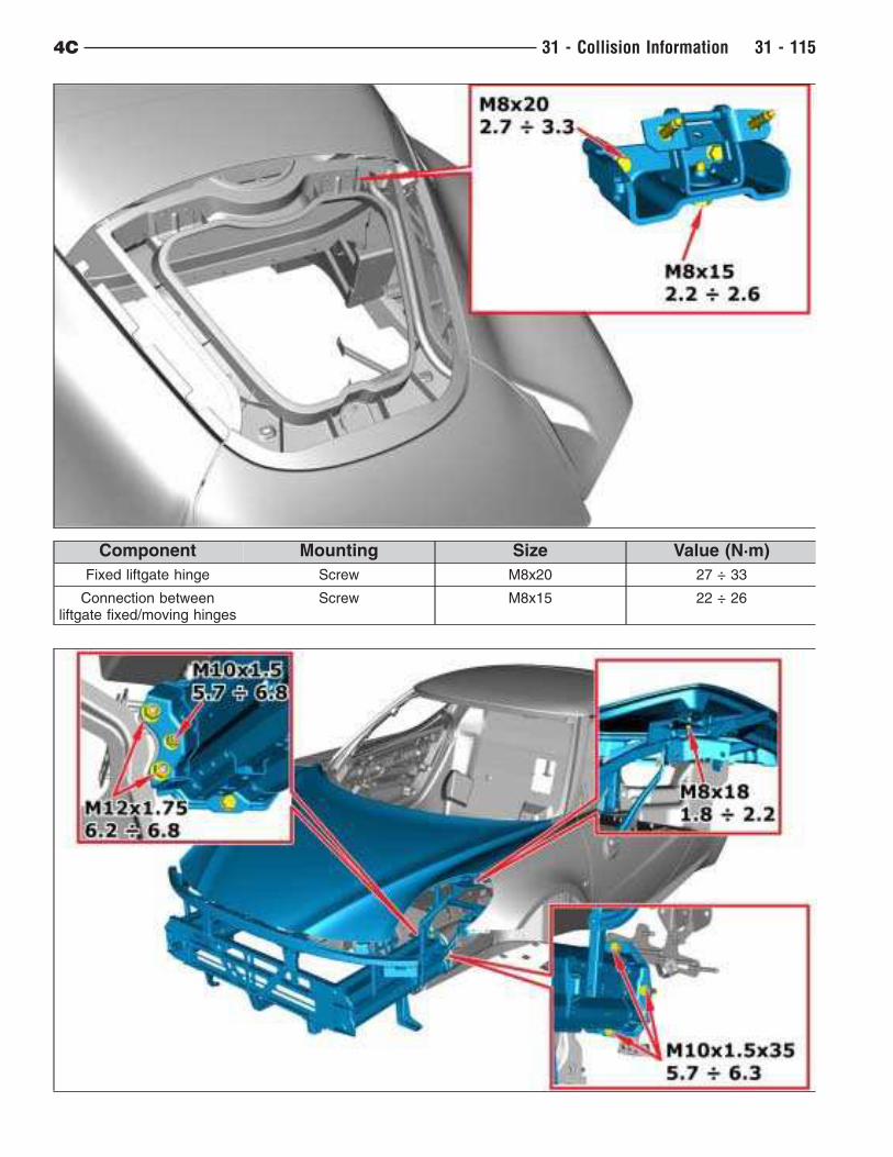
Component Mounting Size Value (N·m)
Fixed liftgate hinge Screw M8x20 27 ÷ 33
Connection betweenliftgate fixed/moving hinges
Screw M8x15 22 ÷ 26
4C 31 - Collision Information 31 - 115
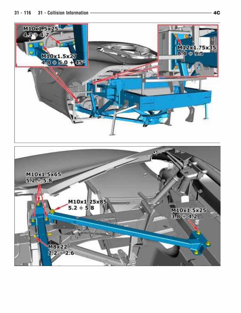
31 - 116 31 - Collision Information 4C
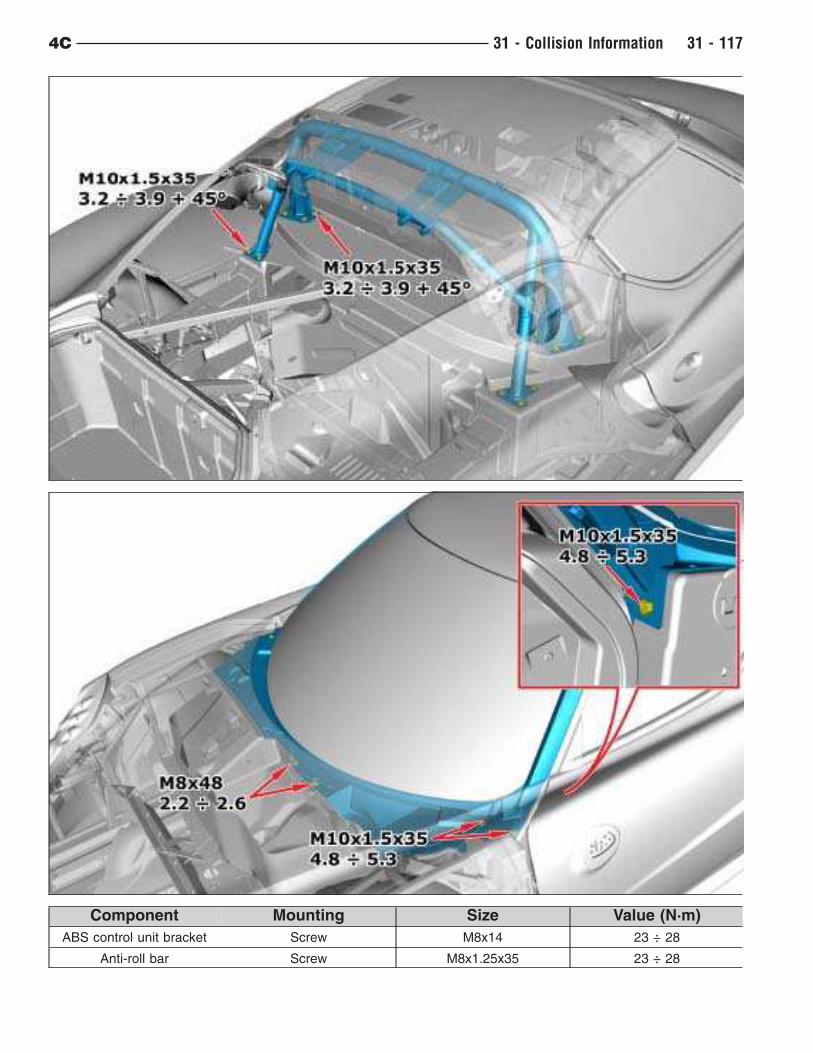
Component Mounting Size Value (N·m)
ABS control unit bracket Screw M8x14 23 ÷ 28
Anti-roll bar Screw M8x1.25x35 23 ÷ 28
4C 31 - Collision Information 31 - 117
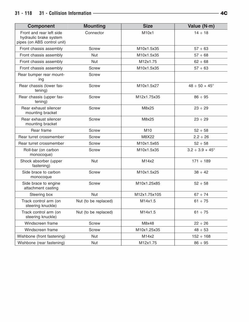
Component Mounting Size Value (N·m)
Front and rear left sidehydraulic brake system
pipes (on ABS control unit)
Connector M10x1 14 ÷ 18
Front chassis assembly Screw M10x1.5x35 57 ÷ 63
Front chassis assembly Nut M10x1.5x35 57 ÷ 68
Front chassis assembly Nut M12x1.75 62 ÷ 68
Front chassis assembly Screw M10x1.5x35 57 ÷ 63
Rear bumper rear mount-ing
Screw
Rear chassis (lower fas-tening)
Screw M10x1.5x27 48 ÷ 50 + 45°
Rear chassis (upper fas-tening)
Screw M12x1.75x35 86 ÷ 95
Rear exhaust silencermounting bracket
Screw M8x25 23 ÷ 29
Rear exhaust silencermounting bracket
Screw M8x25 23 ÷ 29
Rear frame Screw M10 52 ÷ 58
Rear turret crossmember Screw M8X22 2.2 ÷ 26
Rear turret crossmember Screw M10x1.5x65 52 ÷ 58
Roll-bar (on carbonmonocoque)
Screw M10x1.5x35 3.2 ÷ 3.9 + 45°
Shock absorber (upperfastening)
Nut M14x2 171 ÷ 189
Side brace to carbonmonocoque
Screw M10x1.5x25 38 ÷ 42
Side brace to engineattachment casting
Screw M10x1.25x85 52 ÷ 58
Steering box Nut M12x1.75x105 67 ÷ 74
Track control arm (onsteering knuckle)
Nut (to be replaced) M14x1.5 61 ÷ 75
Track control arm (onsteering knuckle)
Nut (to be replaced) M14x1.5 61 ÷ 75
Windscreen frame Screw M8x48 22 ÷ 26
Windscreen frame Screw M10x1.25x35 48 ÷ 53
Wishbone (front fastening) Nut M14x2 152 ÷ 168
Wishbone (rear fastening) Nut M12x1.75 86 ÷ 95
31 - 118 31 - Collision Information 4C
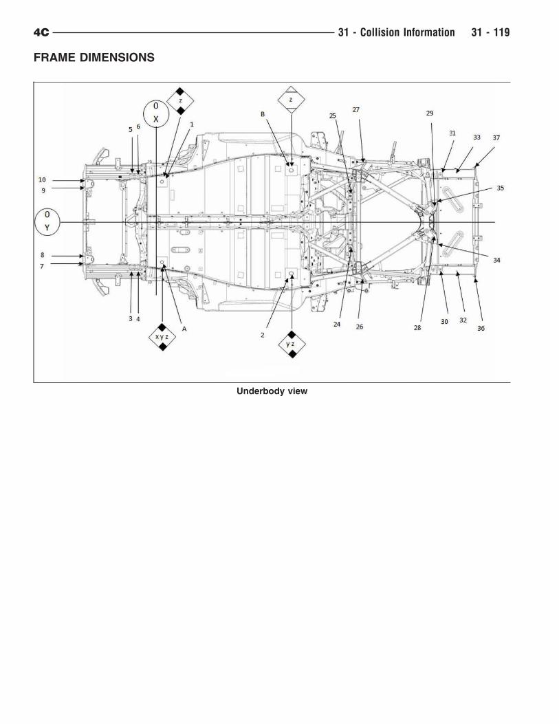
FRAME DIMENSIONS
Underbody view
4C 31 - Collision Information 31 - 119

Side view
Front view
31 - 120 31 - Collision Information 4C
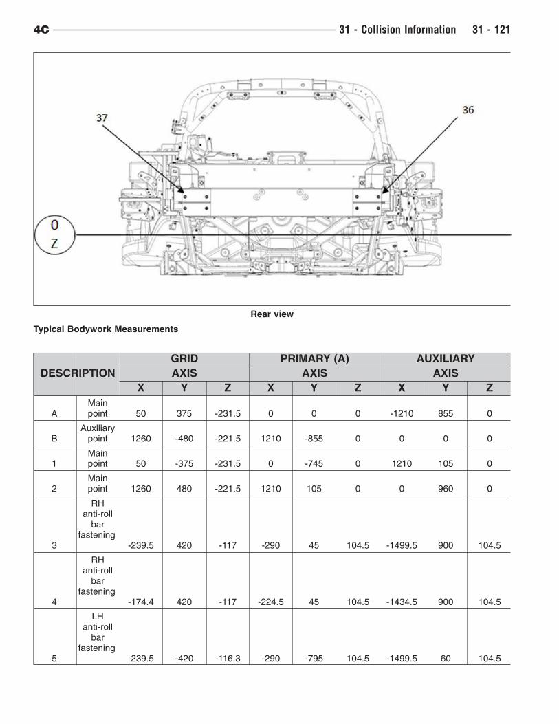
Typical Bodywork Measurements
DESCRIPTION
GRID PRIMARY (A) AUXILIARY
AXIS AXIS AXIS
X Y Z X Y Z X Y Z
AMainpoint 50 375 -231.5 0 0 0 -1210 855 0
BAuxiliary
point 1260 -480 -221.5 1210 -855 0 0 0 0
1Mainpoint 50 -375 -231.5 0 -745 0 1210 105 0
2Mainpoint 1260 480 -221.5 1210 105 0 0 960 0
3
RHanti-roll
barfastening
-239.5 420 -117 -290 45 104.5 -1499.5 900 104.5
4
RHanti-roll
barfastening
-174.4 420 -117 -224.5 45 104.5 -1434.5 900 104.5
5
LHanti-roll
barfastening
-239.5 -420 -116.3 -290 -795 104.5 -1499.5 60 104.5
Rear view
4C 31 - Collision Information 31 - 121
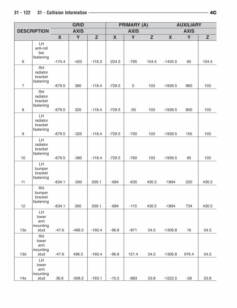
DESCRIPTION
GRID PRIMARY (A) AUXILIARY
AXIS AXIS AXIS
X Y Z X Y Z X Y Z
6
LHanti-roll
barfastening
-174.4 -420 -116.3 -224.5 -795 104.5 -1434.5 60 104.5
7
RHradiatorbracket
fastening-679.5 380 -118.4 -729.5 5 103 -1939.5 860 103
8
RHradiatorbracket
fastening-679.5 320 -118.4 -729.5 -55 103 -1939.5 800 103
9
LHradiatorbracket
fastening-679.5 -325 -118.4 -729.5 -700 103 -1939.5 155 103
10
LHradiatorbracket
fastening-679.5 -385 -118.4 -729.5 -760 103 -1939.5 95 103
11
LHbumperbracket
fastening-634.1 -260 209.1 -684 -635 430.5 -1894 220 430.5
12
RHbumperbracket
fastening-634.1 260 209.1 -684 -115 430.5 -1894 734 430.5
13s
LHlowerarm
mountingstud -47.6 -496.5 -160.4 -96.8 -871 54.5 -1306.8 16 54.5
13d
RHlowerarm
mountingstud -47.6 496.5 -160.4 -96.8 121.4 54.5 -1306.8 976.4 54.5
14s
LHlowerarm
mountingstud 36.6 -508.2 -163.1 -15.5 -883 53.8 -1222.5 -28 53.8
31 - 122 31 - Collision Information 4C
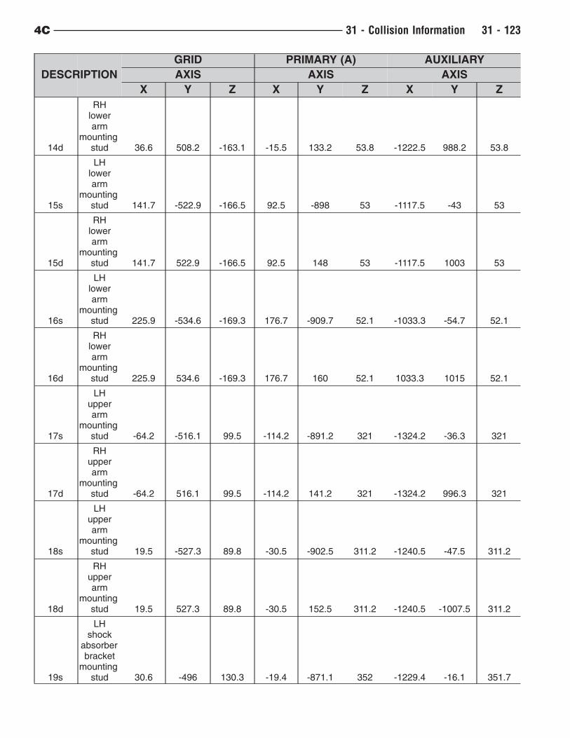
DESCRIPTION
GRID PRIMARY (A) AUXILIARY
AXIS AXIS AXIS
X Y Z X Y Z X Y Z
14d
RHlowerarm
mountingstud 36.6 508.2 -163.1 -15.5 133.2 53.8 -1222.5 988.2 53.8
15s
LHlowerarm
mountingstud 141.7 -522.9 -166.5 92.5 -898 53 -1117.5 -43 53
15d
RHlowerarm
mountingstud 141.7 522.9 -166.5 92.5 148 53 -1117.5 1003 53
16s
LHlowerarm
mountingstud 225.9 -534.6 -169.3 176.7 -909.7 52.1 -1033.3 -54.7 52.1
16d
RHlowerarm
mountingstud 225.9 534.6 -169.3 176.7 160 52.1 1033.3 1015 52.1
17s
LHupperarm
mountingstud -64.2 -516.1 99.5 -114.2 -891.2 321 -1324.2 -36.3 321
17d
RHupperarm
mountingstud -64.2 516.1 99.5 -114.2 141.2 321 -1324.2 996.3 321
18s
LHupperarm
mountingstud 19.5 -527.3 89.8 -30.5 -902.5 311.2 -1240.5 -47.5 311.2
18d
RHupperarm
mountingstud 19.5 527.3 89.8 -30.5 152.5 311.2 -1240.5 -1007.5 311.2
19s
LHshock
absorberbracket
mountingstud 30.6 -496 130.3 -19.4 -871.1 352 -1229.4 -16.1 351.7
4C 31 - Collision Information 31 - 123
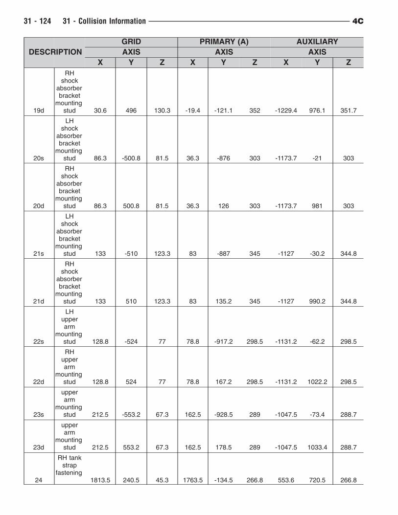
DESCRIPTION
GRID PRIMARY (A) AUXILIARY
AXIS AXIS AXIS
X Y Z X Y Z X Y Z
19d
RHshock
absorberbracket
mountingstud 30.6 496 130.3 -19.4 -121.1 352 -1229.4 976.1 351.7
20s
LHshock
absorberbracket
mountingstud 86.3 -500.8 81.5 36.3 -876 303 -1173.7 -21 303
20d
RHshock
absorberbracket
mountingstud 86.3 500.8 81.5 36.3 126 303 -1173.7 981 303
21s
LHshock
absorberbracket
mountingstud 133 -510 123.3 83 -887 345 -1127 -30.2 344.8
21d
RHshock
absorberbracket
mountingstud 133 510 123.3 83 135.2 345 -1127 990.2 344.8
22s
LHupperarm
mountingstud 128.8 -524 77 78.8 -917.2 298.5 -1131.2 -62.2 298.5
22d
RHupperarm
mountingstud 128.8 524 77 78.8 167.2 298.5 -1131.2 1022.2 298.5
23s
upperarm
mountingstud 212.5 -553.2 67.3 162.5 -928.5 289 -1047.5 -73.4 288.7
23d
upperarm
mountingstud 212.5 553.2 67.3 162.5 178.5 289 -1047.5 1033.4 288.7
24
RH tankstrap
fastening1813.5 240.5 45.3 1763.5 -134.5 266.8 553.6 720.5 266.8
31 - 124 31 - Collision Information 4C
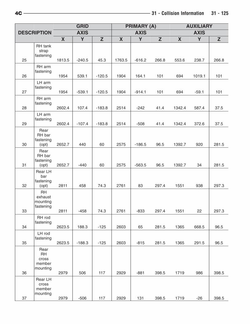
DESCRIPTION
GRID PRIMARY (A) AUXILIARY
AXIS AXIS AXIS
X Y Z X Y Z X Y Z
25
RH tankstrap
fastening1813.5 -240.5 45.3 1763.5 -616.2 266.8 553.6 238.7 266.8
26
RH armfastening
1954 539.1 -120.5 1904 164.1 101 694 1019.1 101
27
LH armfastening
1954 -539.1 -120.5 1904 -914.1 101 694 -59.1 101
28
RH armfastening
2602.4 107.4 -183.8 2514 -242 41.4 1342.4 587.4 37.5
29
LH armfastening
2602.4 -107.4 -183.8 2514 -508 41.4 1342.4 372.6 37.5
30
RearRH bar
fastening(opt) 2652.7 440 60 2575 -186.5 96.5 1392.7 920 281.5
31
RearRH bar
fastening(opt) 2652.7 -440 60 2575 -563.5 96.5 1392.7 34 281.5
32
Rear LHbar
fastening(opt) 2811 458 74.3 2761 83 297.4 1551 938 297.3
33
RHexhaust
mountingfastening
2811 -458 74.3 2761 -833 297.4 1551 22 297.3
34
RH rodfastening
2623.5 188.3 -125 2603 65 281.5 1365 668.5 96.5
35
LH rodfastening
2623.5 -188.3 -125 2603 -815 281.5 1365 291.5 96.5
36
RearRH
crossmember
mounting2979 506 117 2929 -881 398.5 1719 986 398.5
37
Rear LHcross
membermounting
2979 -506 117 2929 131 398.5 1719 -26 398.5
4C 31 - Collision Information 31 - 125
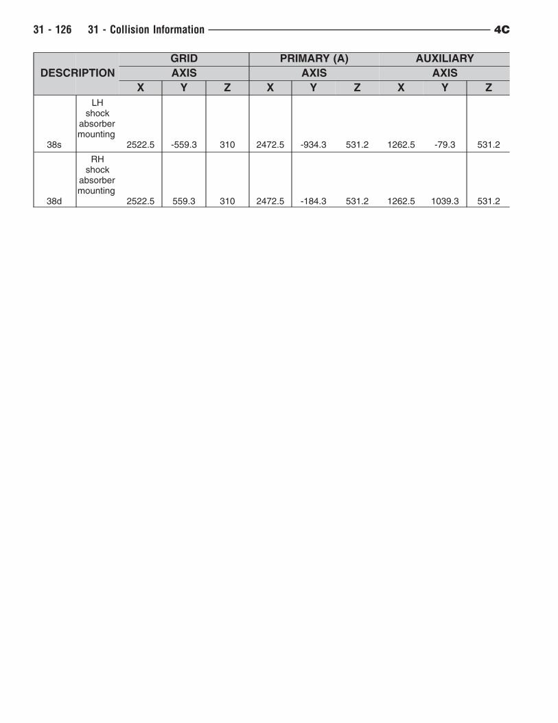
DESCRIPTION
GRID PRIMARY (A) AUXILIARY
AXIS AXIS AXIS
X Y Z X Y Z X Y Z
38s
LHshock
absorbermounting
2522.5 -559.3 310 2472.5 -934.3 531.2 1262.5 -79.3 531.2
38d
RHshock
absorbermounting
2522.5 559.3 310 2472.5 -184.3 531.2 1262.5 1039.3 531.2
31 - 126 31 - Collision Information 4C
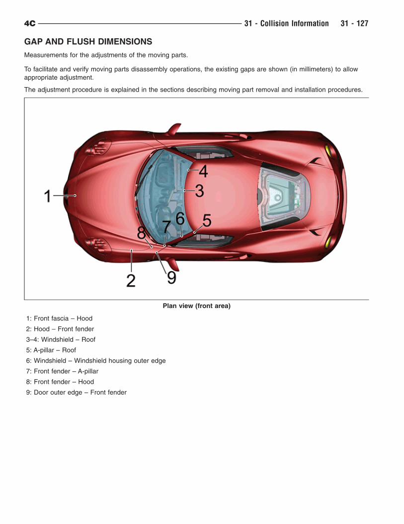
GAP AND FLUSH DIMENSIONS
Measurements for the adjustments of the moving parts.
To facilitate and verify moving parts disassembly operations, the existing gaps are shown (in millimeters) to allow
appropriate adjustment.
The adjustment procedure is explained in the sections describing moving part removal and installation procedures.
1: Front fascia – Hood
2: Hood – Front fender
3–4: Windshield – Roof
5: A-pillar – Roof
6: Windshield – Windshield housing outer edge
7: Front fender – A-pillar
8: Front fender – Hood
9: Door outer edge – Front fender
Plan view (front area)
4C 31 - Collision Information 31 - 127
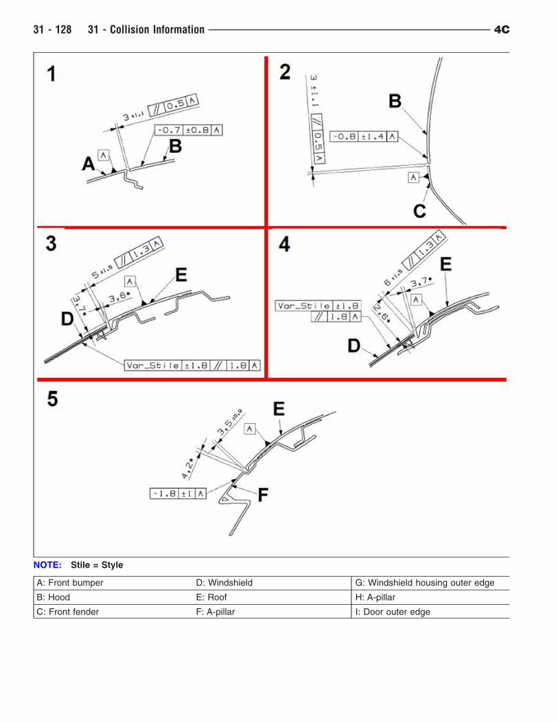
A: Front bumper D: Windshield G: Windshield housing outer edge
B: Hood E: Roof H: A-pillar
C: Front fender F: A-pillar I: Door outer edge
NOTE: Stile = Style
31 - 128 31 - Collision Information 4C
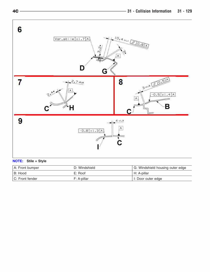
A: Front bumper D: Windshield G: Windshield housing outer edge
B: Hood E: Roof H: A-pillar
C: Front fender F: A-pillar I: Door outer edge
NOTE: Stile = Style
4C 31 - Collision Information 31 - 129
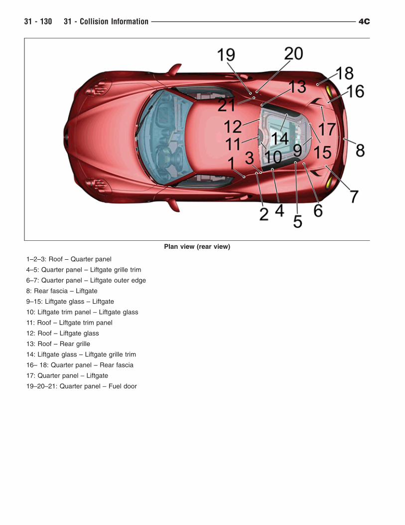
1–2–3: Roof – Quarter panel
4–5: Quarter panel – Liftgate grille trim
6–7: Quarter panel – Liftgate outer edge
8: Rear fascia – Liftgate
9–15: Liftgate glass – Liftgate
10: Liftgate trim panel – Liftgate glass
11: Roof – Liftgate trim panel
12: Roof – Liftgate glass
13: Roof – Rear grille
14: Liftgate glass – Liftgate grille trim
16– 18: Quarter panel – Rear fascia
17: Quarter panel – Liftgate
19–20–21: Quarter panel – Fuel door
Plan view (rear view)
31 - 130 31 - Collision Information 4C
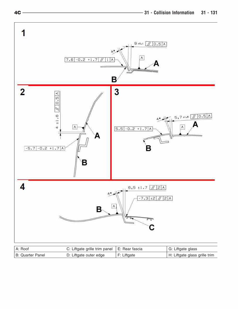
A: Roof C: Liftgate grille trim panel E: Rear fascia G: Liftgate glass
B: Quarter Panel D: Liftgate outer edge F: Liftgate H: Liftgate glass grille trim
4C 31 - Collision Information 31 - 131
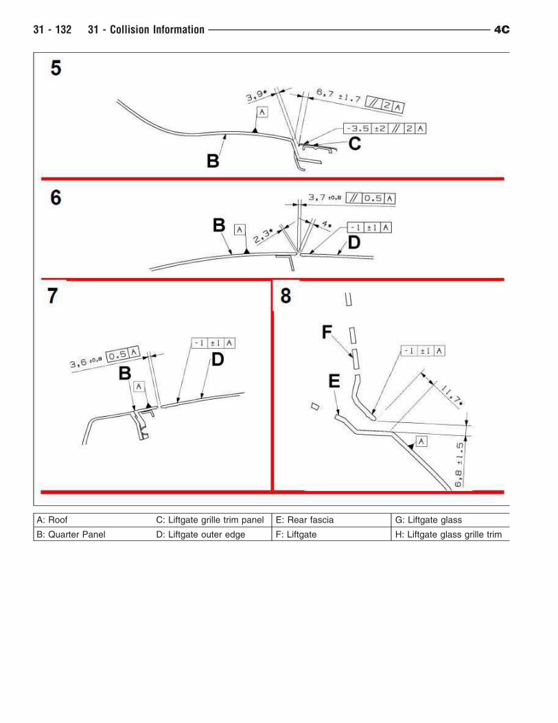
A: Roof C: Liftgate grille trim panel E: Rear fascia G: Liftgate glass
B: Quarter Panel D: Liftgate outer edge F: Liftgate H: Liftgate glass grille trim
31 - 132 31 - Collision Information 4C
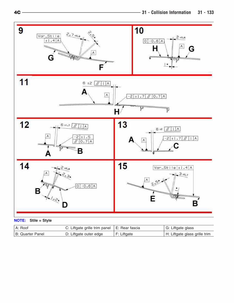
A: Roof C: Liftgate grille trim panel E: Rear fascia G: Liftgate glass
B: Quarter Panel D: Liftgate outer edge F: Liftgate H: Liftgate glass grille trim
NOTE: Stile = Style
4C 31 - Collision Information 31 - 133
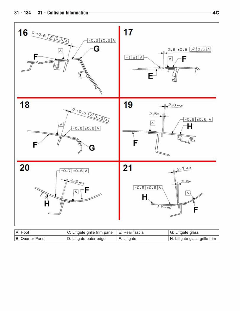
A: Roof C: Liftgate grille trim panel E: Rear fascia G: Liftgate glass
B: Quarter Panel D: Liftgate outer edge F: Liftgate H: Liftgate glass grille trim
31 - 134 31 - Collision Information 4C
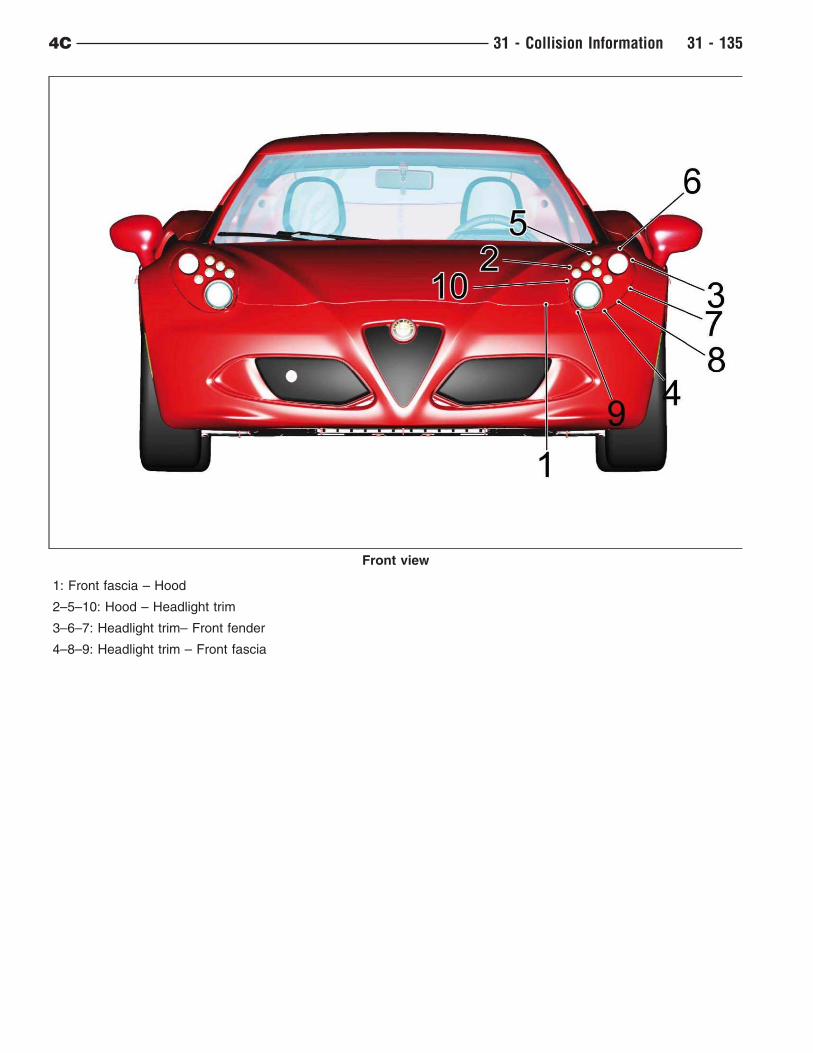
1: Front fascia – Hood
2–5–10: Hood – Headlight trim
3–6–7: Headlight trim– Front fender
4–8–9: Headlight trim – Front fascia
Front view
4C 31 - Collision Information 31 - 135
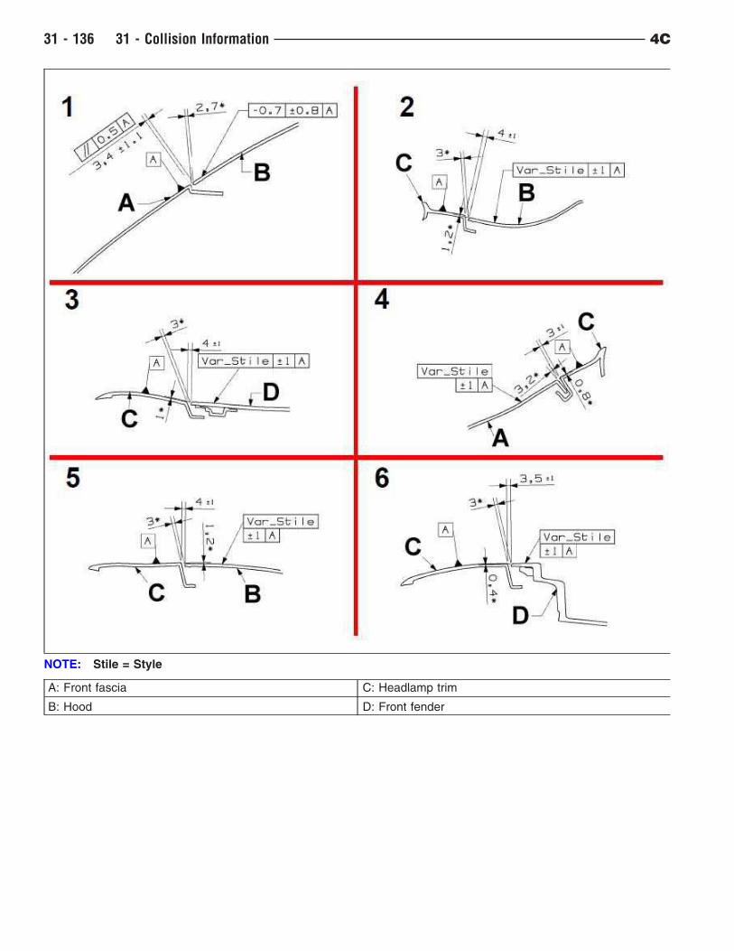
A: Front fascia C: Headlamp trim
B: Hood D: Front fender
NOTE: Stile = Style
31 - 136 31 - Collision Information 4C
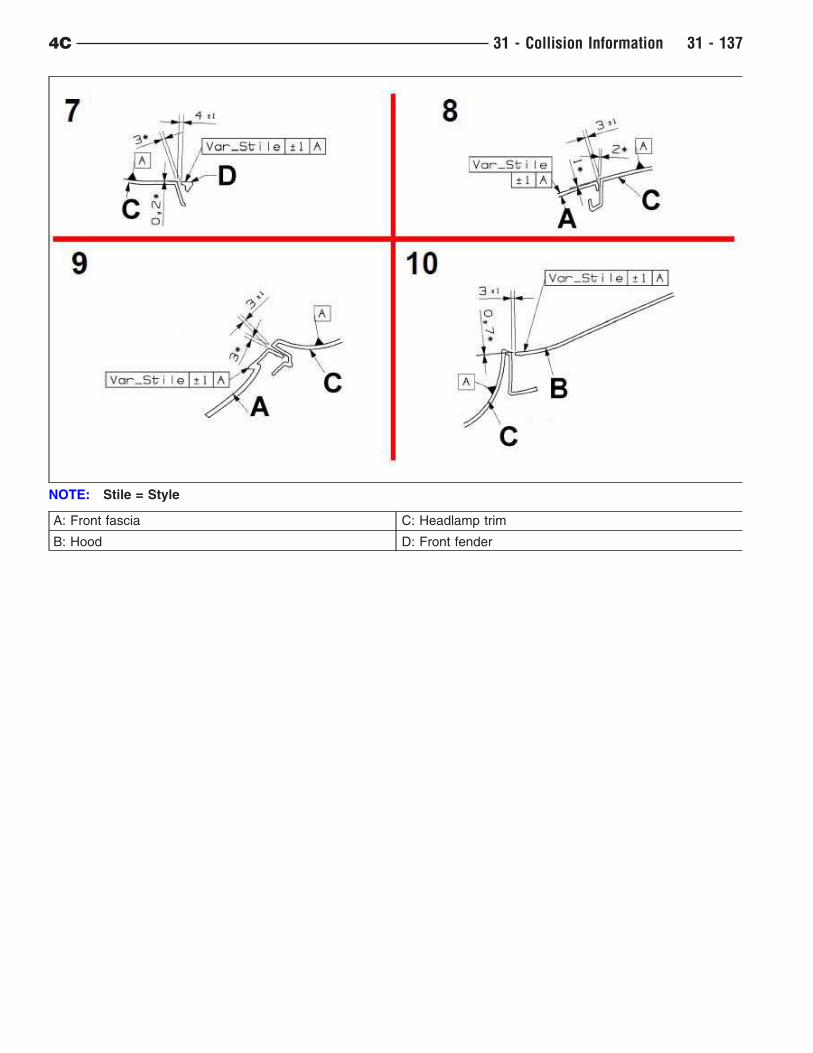
A: Front fascia C: Headlamp trim
B: Hood D: Front fender
NOTE: Stile = Style
4C 31 - Collision Information 31 - 137
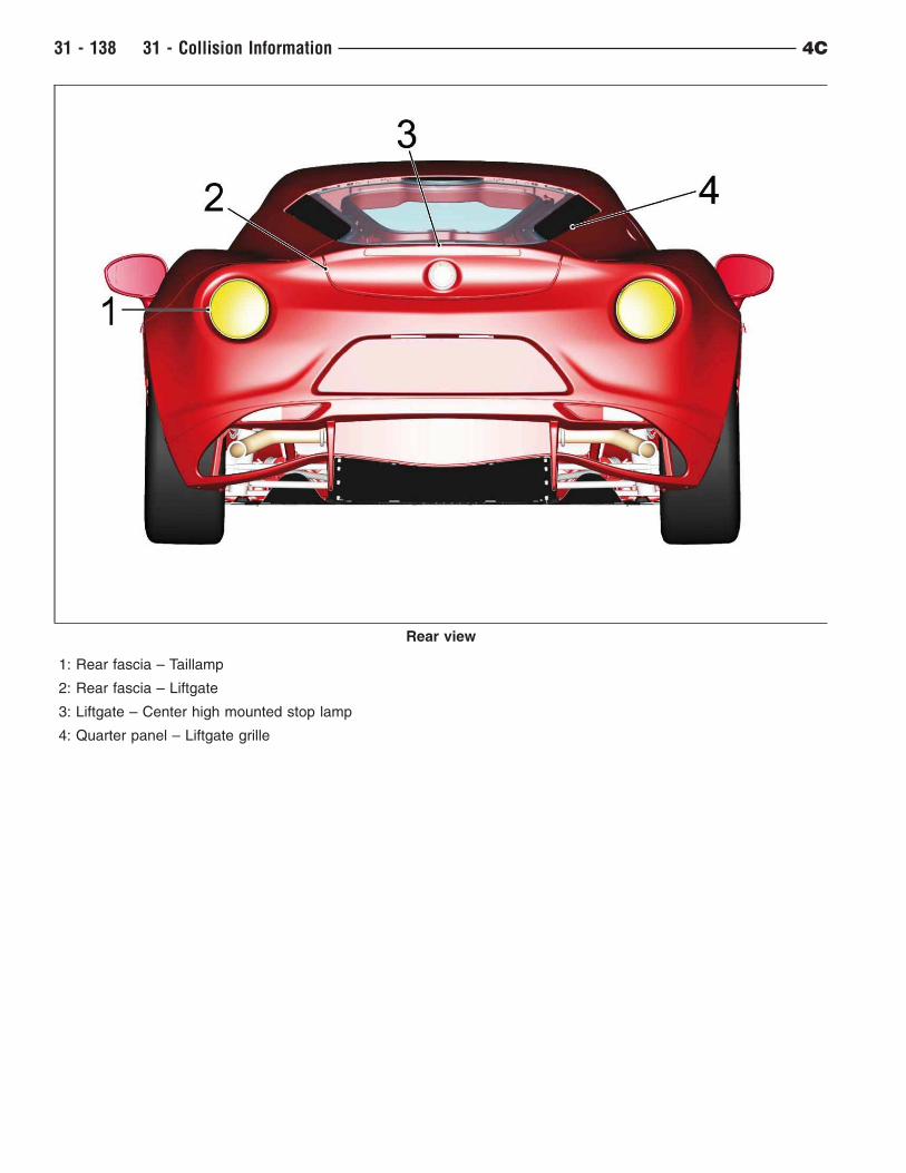
1: Rear fascia – Taillamp
2: Rear fascia – Liftgate
3: Liftgate – Center high mounted stop lamp
4: Quarter panel – Liftgate grille
Rear view
31 - 138 31 - Collision Information 4C
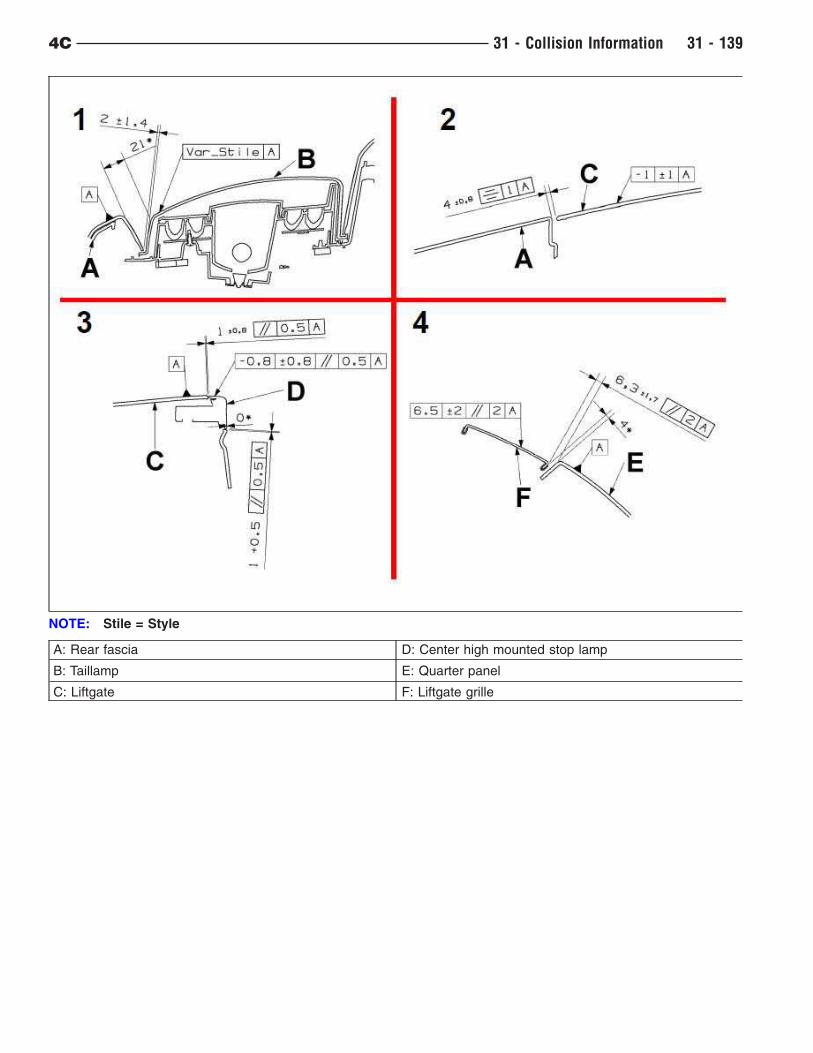
A: Rear fascia D: Center high mounted stop lamp
B: Taillamp E: Quarter panel
C: Liftgate F: Liftgate grille
NOTE: Stile = Style
4C 31 - Collision Information 31 - 139
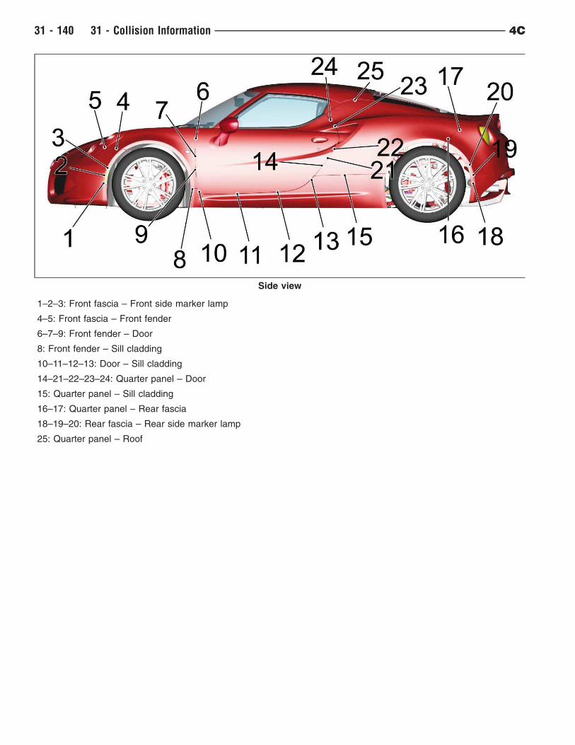
1–2–3: Front fascia – Front side marker lamp
4–5: Front fascia – Front fender
6–7–9: Front fender – Door
8: Front fender – Sill cladding
10–11–12–13: Door – Sill cladding
14–21–22–23–24: Quarter panel – Door
15: Quarter panel – Sill cladding
16–17: Quarter panel – Rear fascia
18–19–20: Rear fascia – Rear side marker lamp
25: Quarter panel – Roof
Side view
31 - 140 31 - Collision Information 4C
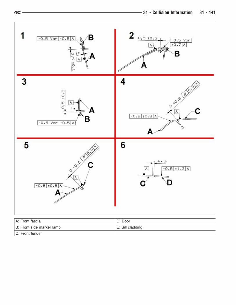
A: Front fascia D: Door
B: Front side marker lamp E: Sill cladding
C: Front fender
4C 31 - Collision Information 31 - 141
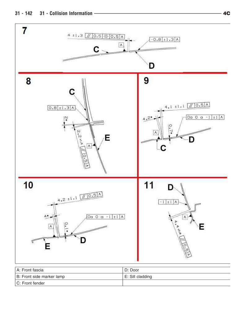
A: Front fascia D: Door
B: Front side marker lamp E: Sill cladding
C: Front fender
31 - 142 31 - Collision Information 4C
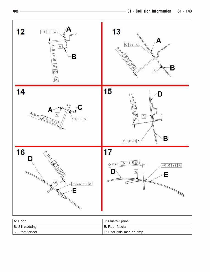
A: Door D: Quarter panel
B: Sill cladding E: Rear fascia
C: Front fender F: Rear side marker lamp
4C 31 - Collision Information 31 - 143
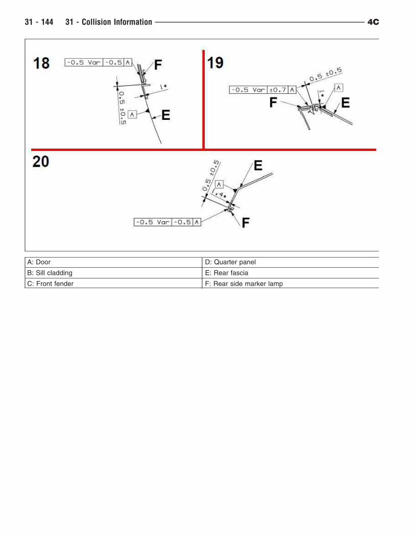
A: Door D: Quarter panel
B: Sill cladding E: Rear fascia
C: Front fender F: Rear side marker lamp
31 - 144 31 - Collision Information 4C
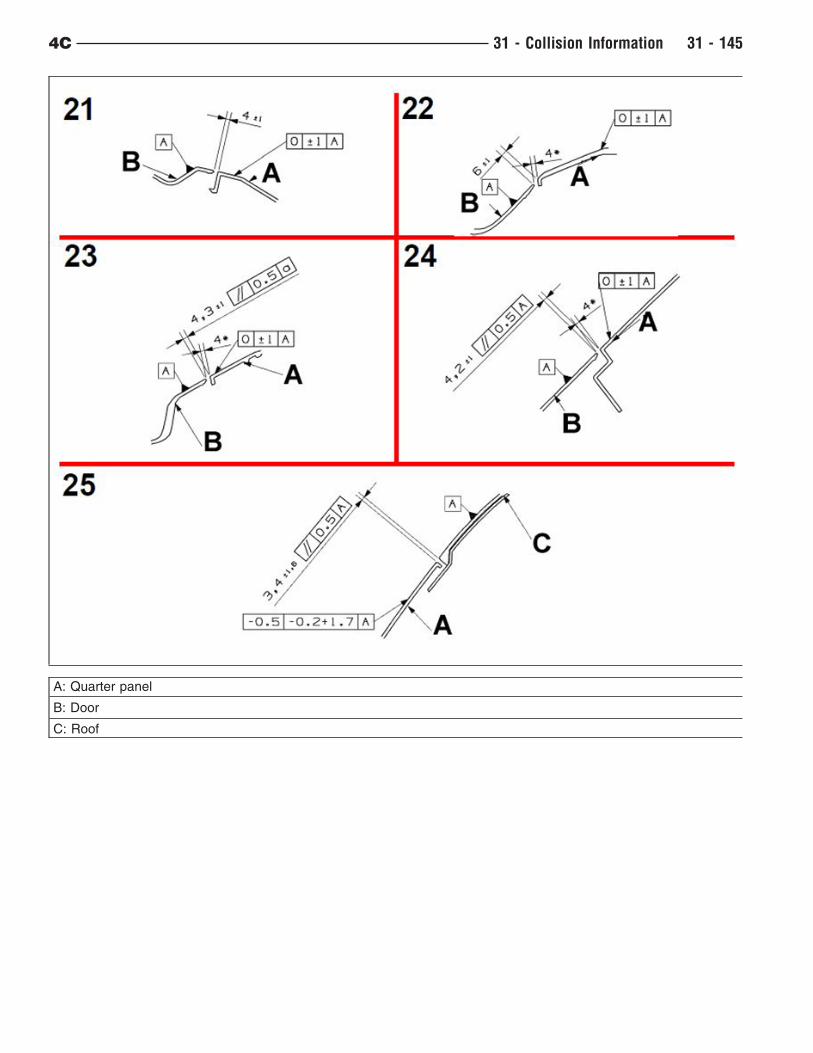
A: Quarter panel
B: Door
C: Roof
4C 31 - Collision Information 31 - 145
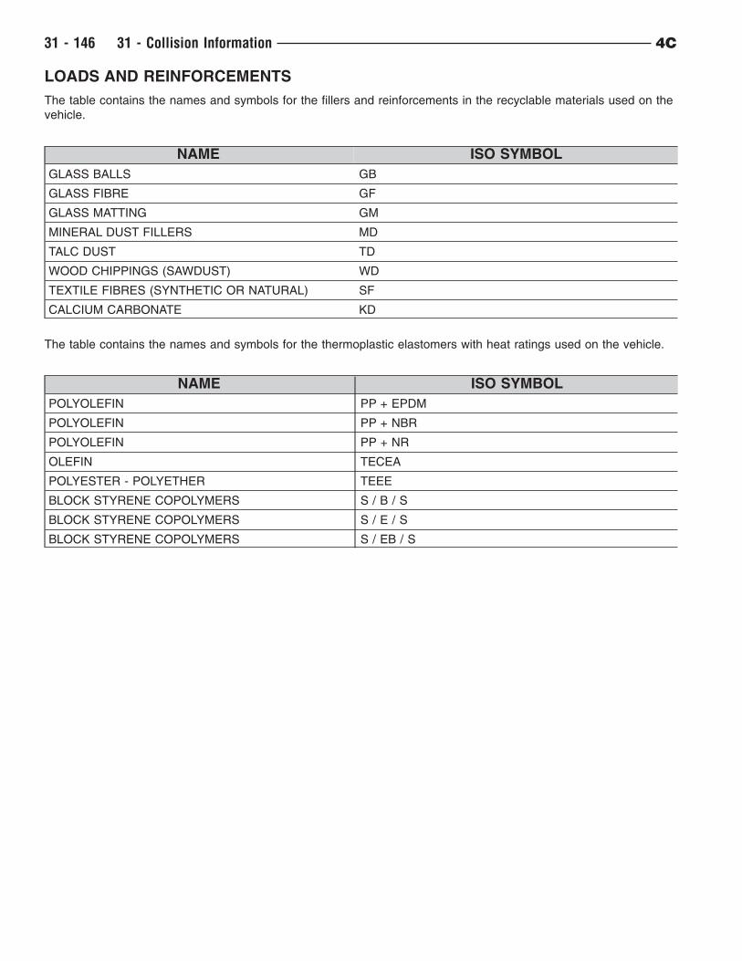
LOADS AND REINFORCEMENTS
The table contains the names and symbols for the fillers and reinforcements in the recyclable materials used on the
vehicle.
NAME ISO SYMBOL
GLASS BALLS GB
GLASS FIBRE GF
GLASS MATTING GM
MINERAL DUST FILLERS MD
TALC DUST TD
WOOD CHIPPINGS (SAWDUST) WD
TEXTILE FIBRES (SYNTHETIC OR NATURAL) SF
CALCIUM CARBONATE KD
The table contains the names and symbols for the thermoplastic elastomers with heat ratings used on the vehicle.
NAME ISO SYMBOL
POLYOLEFIN PP + EPDM
POLYOLEFIN PP + NBR
POLYOLEFIN PP + NR
OLEFIN TECEA
POLYESTER - POLYETHER TEEE
BLOCK STYRENE COPOLYMERS S / B / S
BLOCK STYRENE COPOLYMERS S / E / S
BLOCK STYRENE COPOLYMERS S / EB / S
31 - 146 31 - Collision Information 4C
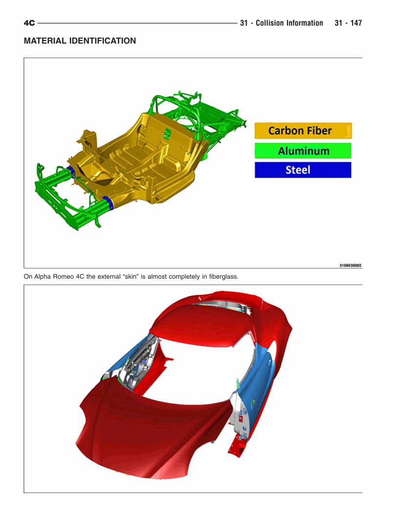
MATERIAL IDENTIFICATION
On Alpha Romeo 4C the external “skin” is almost completely in fiberglass.
4C 31 - Collision Information 31 - 147

31 - 148 31 - Collision Information 4C
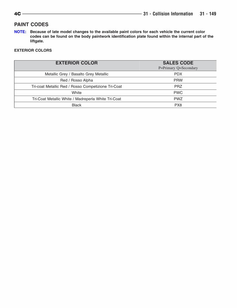
PAINT CODES
NOTE: Because of late model changes to the available paint colors for each vehicle the current color
codes can be found on the body paintwork identification plate found within the internal part of the
liftgate.
EXTERIOR COLORS
EXTERIOR COLOR SALES CODEP=Primary Q=Secondary
Metallic Grey / Basalto Grey Metallic PDX
Red / Rosso Alpha PRW
Tri-coat Metallic Red / Rosso Competizione Tri-Coat PRZ
White PWC
Tri-Coat Metallic White / Madreperla White Tri-Coat PWZ
Black PX8
4C 31 - Collision Information 31 - 149
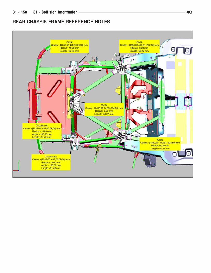
REAR CHASSIS FRAME REFERENCE HOLES
31 - 150 31 - Collision Information 4C
THERMOHARDENING RECYCLABLE MATERIALS
The table contains the names and symbols of the main thermohardening materials used on the vehicle.
NAME ISO SYMBOL
PHENOLS PF
POLYURETHANES PUR
THERMOSETTING UNSATURATEDPOLYESTERS
–
- For compression moulding (SMC) UP
- For injection moulding (BMC) UP
4C 31 - Collision Information 31 - 151
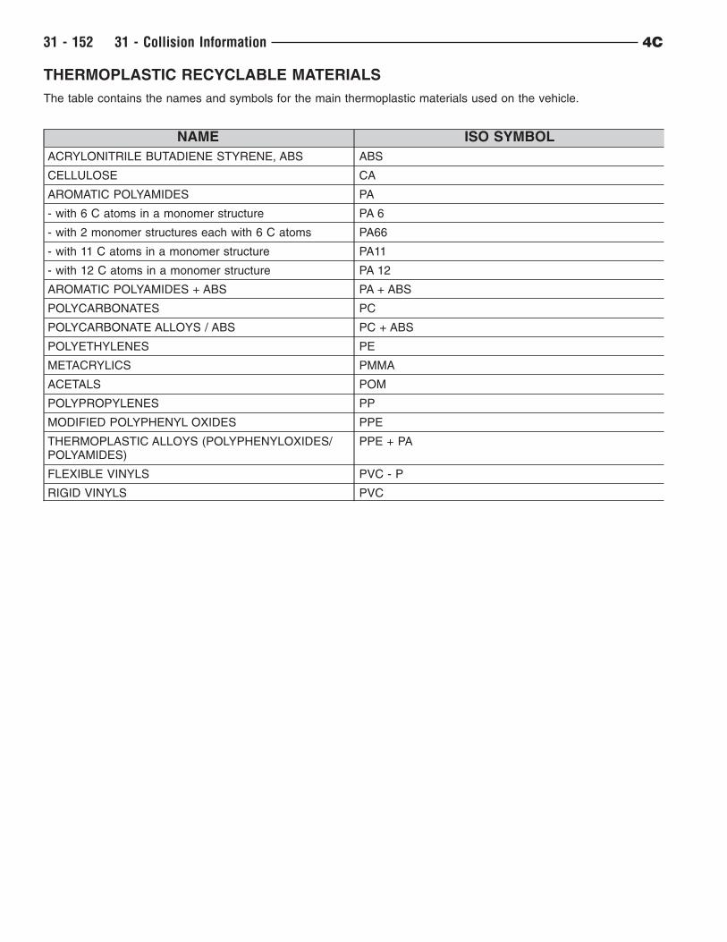
THERMOPLASTIC RECYCLABLE MATERIALS
The table contains the names and symbols for the main thermoplastic materials used on the vehicle.
NAME ISO SYMBOL
ACRYLONITRILE BUTADIENE STYRENE, ABS ABS
CELLULOSE CA
AROMATIC POLYAMIDES PA
- with 6 C atoms in a monomer structure PA 6
- with 2 monomer structures each with 6 C atoms PA66
- with 11 C atoms in a monomer structure PA11
- with 12 C atoms in a monomer structure PA 12
AROMATIC POLYAMIDES + ABS PA + ABS
POLYCARBONATES PC
POLYCARBONATE ALLOYS / ABS PC + ABS
POLYETHYLENES PE
METACRYLICS PMMA
ACETALS POM
POLYPROPYLENES PP
MODIFIED POLYPHENYL OXIDES PPE
THERMOPLASTIC ALLOYS (POLYPHENYLOXIDES/POLYAMIDES)
PPE + PA
FLEXIBLE VINYLS PVC - P
RIGID VINYLS PVC
31 - 152 31 - Collision Information 4C
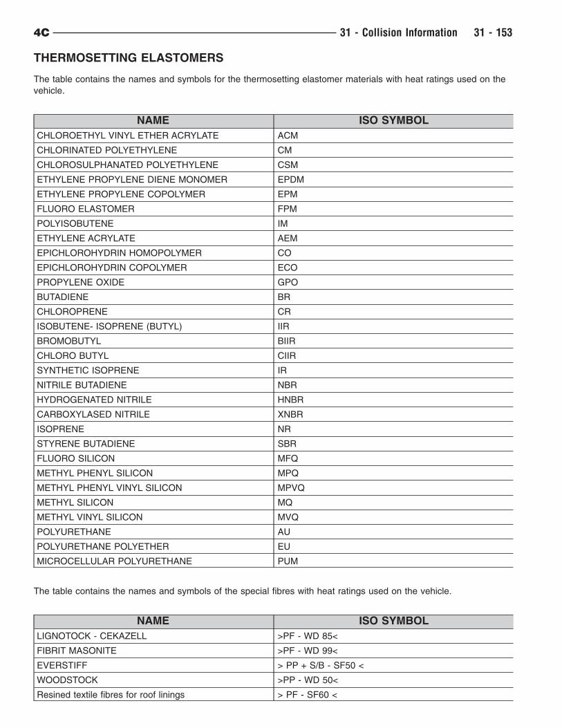
THERMOSETTING ELASTOMERS
The table contains the names and symbols for the thermosetting elastomer materials with heat ratings used on the
vehicle.
NAME ISO SYMBOL
CHLOROETHYL VINYL ETHER ACRYLATE ACM
CHLORINATED POLYETHYLENE CM
CHLOROSULPHANATED POLYETHYLENE CSM
ETHYLENE PROPYLENE DIENE MONOMER EPDM
ETHYLENE PROPYLENE COPOLYMER EPM
FLUORO ELASTOMER FPM
POLYISOBUTENE IM
ETHYLENE ACRYLATE AEM
EPICHLOROHYDRIN HOMOPOLYMER CO
EPICHLOROHYDRIN COPOLYMER ECO
PROPYLENE OXIDE GPO
BUTADIENE BR
CHLOROPRENE CR
ISOBUTENE- ISOPRENE (BUTYL) IIR
BROMOBUTYL BIIR
CHLORO BUTYL CIIR
SYNTHETIC ISOPRENE IR
NITRILE BUTADIENE NBR
HYDROGENATED NITRILE HNBR
CARBOXYLASED NITRILE XNBR
ISOPRENE NR
STYRENE BUTADIENE SBR
FLUORO SILICON MFQ
METHYL PHENYL SILICON MPQ
METHYL PHENYL VINYL SILICON MPVQ
METHYL SILICON MQ
METHYL VINYL SILICON MVQ
POLYURETHANE AU
POLYURETHANE POLYETHER EU
MICROCELLULAR POLYURETHANE PUM
The table contains the names and symbols of the special fibres with heat ratings used on the vehicle.
NAME ISO SYMBOL
LIGNOTOCK - CEKAZELL >PF - WD 85<
FIBRIT MASONITE >PF - WD 99<
EVERSTIFF > PP + S/B - SF50 <
WOODSTOCK >PP - WD 50<
Resined textile fibres for roof linings > PF - SF60 <
4C 31 - Collision Information 31 - 153

NAME ISO SYMBOL
Resined textile fibres for sound insulation > PF - SF70 <
Glass fibre matting + resined textile fibres for roof lining > GM, PF - SF60 <
GLASUTEC >GM, PUR, GM
GLASUTHERM > GM, PUR, GM <
GLASS - FOAM > PUR - GF30 <
31 - 154 31 - Collision Information 4C
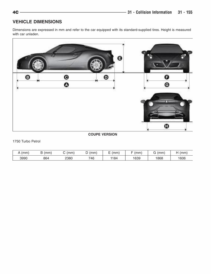
VEHICLE DIMENSIONS
Dimensions are expressed in mm and refer to the car equipped with its standard-supplied tires. Height is measured
with car unladen.
1750 Turbo Petrol
A (mm) B (mm) C (mm) D (mm) E (mm) F (mm) G (mm) H (mm)
3990 864 2380 746 1184 1639 1868 1606
COUPE VERSION
4C 31 - Collision Information 31 - 155
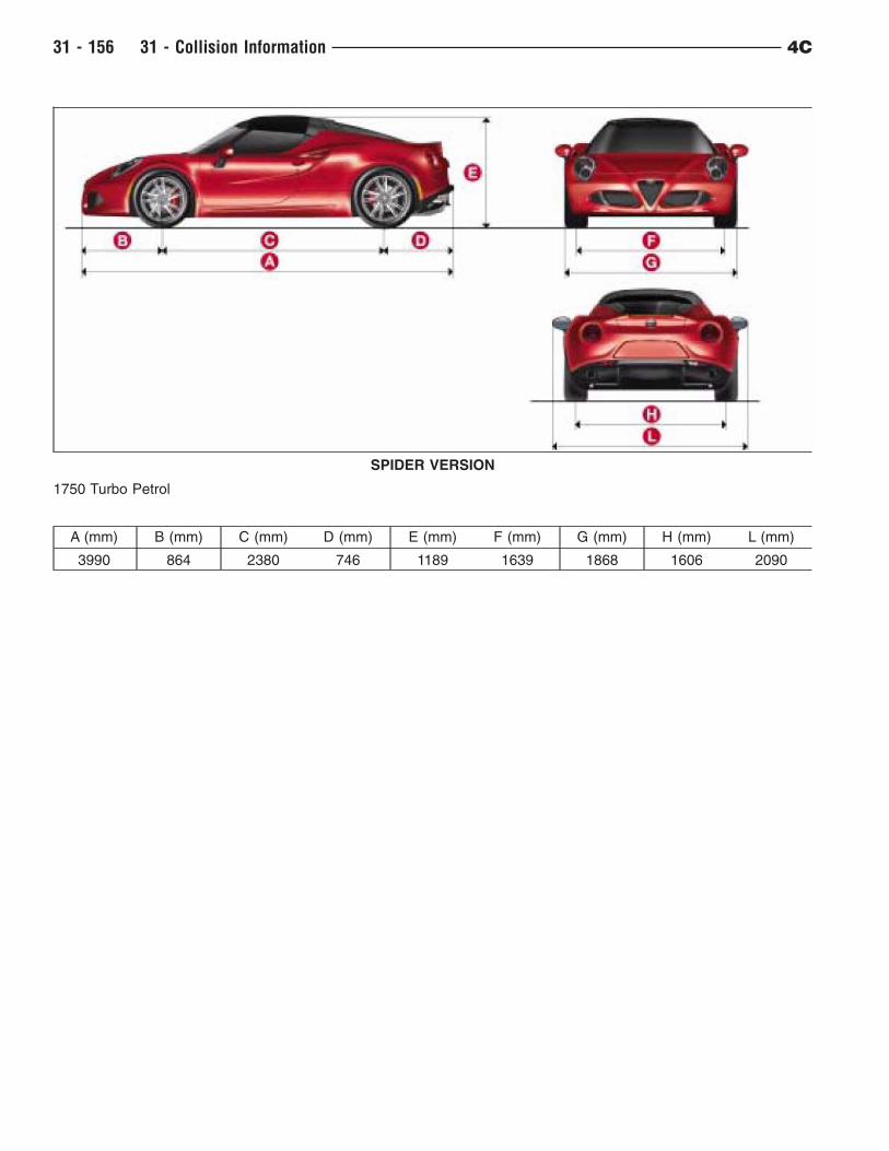
1750 Turbo Petrol
A (mm) B (mm) C (mm) D (mm) E (mm) F (mm) G (mm) H (mm) L (mm)
3990 864 2380 746 1189 1639 1868 1606 2090
SPIDER VERSION
31 - 156 31 - Collision Information 4C
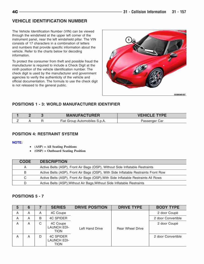
VEHICLE IDENTIFICATION NUMBER
The Vehicle Identification Number (VIN) can be viewed
through the windshield at the upper left corner of the
instrument panel, near the left windshield pillar. The VIN
consists of 17 characters in a combination of letters
and numbers that provide specific information about the
vehicle. Refer to the charts below for decoding
information.
To protect the consumer from theft and possible fraud the
manufacturer is required to include a Check Digit at the
ninth position of the vehicle identification number. The
check digit is used by the manufacturer and government
agencies to verify the authenticity of the vehicle and
official documentation. The formula to use the check digit
is not released to the general public.
POSITIONS 1 - 3: WORLD MANUFACTURER IDENTIFIER
1 2 3 MANUFACTURER VEHICLE TYPE
Z A R Fiat Group Automobiles S.p.A. Passenger Car
POSITION 4: RESTRAINT SYSTEM
NOTE:
• (ASP) = All Seating Positions
• (OSP) = Outboard Seating Position
CODE DESCRIPTION
A Active Belts (ASP), Front Air Bags (OSP), Without Side Inflatable Restraints
B Active Belts (ASP), Front Air Bags (OSP), With Side Inflatable Restraints Front Row
C Active Belts (ASP), Front Air Bags (OSP),With Side Inflatable Restraints All Rows
D Active Belts (ASP),Without Air Bags,Without Side Inflatable Restraints
POSITIONS 5 - 7
5 6 7 SERIES DRIVE POSITION DRIVE TYPE BODY TYPE
A A A 4C Coupe
Left Hand Drive Rear Wheel Drive
2 door Coupè
A A B 4C SPIDER 2 door Convertible
A A C 4C CoupeLAUNCH EDI-
TION
2 door Coupè
A A D 4C SPIDERLAUNCH EDI-
TION
2 door Convertible
4C 31 - Collision Information 31 - 157
POSITION 8: ENGINE
CODE DISPLACEMENT CYLINDERS FUEL TURBO SALESCODES
4 1750 4 Gasoline Yes EBC
POSITION 9: CHECK DIGIT
0 through 9 or X
POSITION 10: MODEL YEAR
F = 2015
POSITION 11: ASSEMBLY PLANT
CODE PLANT
M MASERATI PLANT MODENA (ITALY)
POSITION 12 - 17: PLANT SEQUENCE NUMBER
A six digit number assigned by assembly plant.
Locations
31 - 158 31 - Collision Information 4C

BODY MARKING
The marking is printed on the passenger compartment floor panel, near the passenger side seat.
– Vehicle type
– Vehicle manufacture serial number (chassis number)
4C 31 - Collision Information 31 - 159
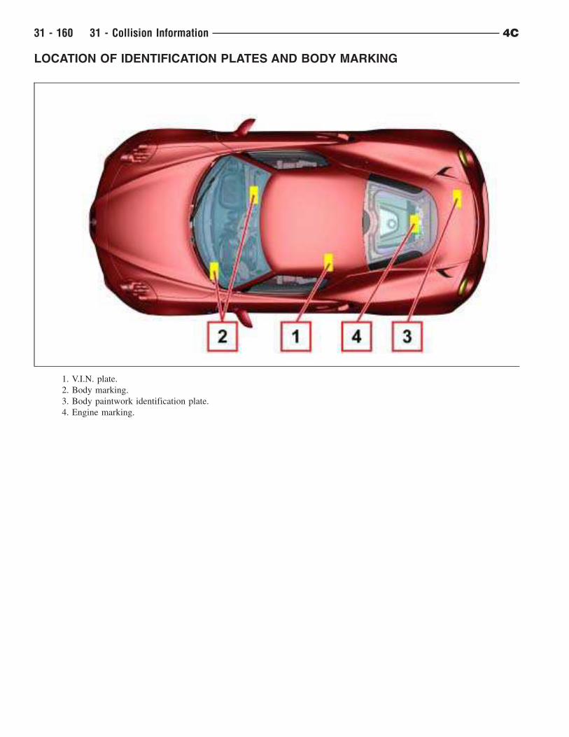
LOCATION OF IDENTIFICATION PLATES AND BODY MARKING
1. V.I.N. plate.
2. Body marking.
3. Body paintwork identification plate.
4. Engine marking.
31 - 160 31 - Collision Information 4C
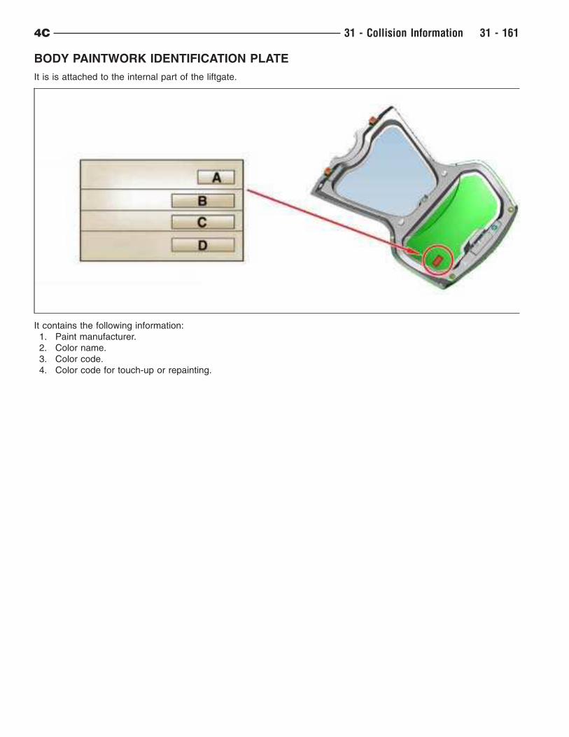
BODY PAINTWORK IDENTIFICATION PLATE
It is is attached to the internal part of the liftgate.
It contains the following information:
1. Paint manufacturer.
2. Color name.
3. Color code.
4. Color code for touch-up or repainting.
4C 31 - Collision Information 31 - 161

INDEX
INDEX - 1


![P µ î t ^ µ o Ç ] o t } l · 3q 4c 4c 4c4 4c 4c4 4c 4c 4c44c q3 4c 4c4 4c 4c 4c 4!(!(!(!(!(!(!(!(!(!(!!(!!!!!(!(!(!(!(!(!!(!(!(wps26 wps19 wps10 wps24 wps23 wps25 wps01 wps20](https://img.pdfslide.us/doc/110x75/5f69b696a9d73730bd76a7d7/p-t-o-o-t-l-3q-4c-4c-4c4-4c-4c4-4c-4c-4c44c-q3-4c-4c4-4c-4c-4c.jpg)