Embed Size (px)
Citation preview
MTD LLC, P.O. BOX 361131 CLEVELAND, OHIO 44136-0019
Printed In USA
Safe Operation Practices • Set-Up • Operation • Maintenance • Service • Troubleshooting • Warranty
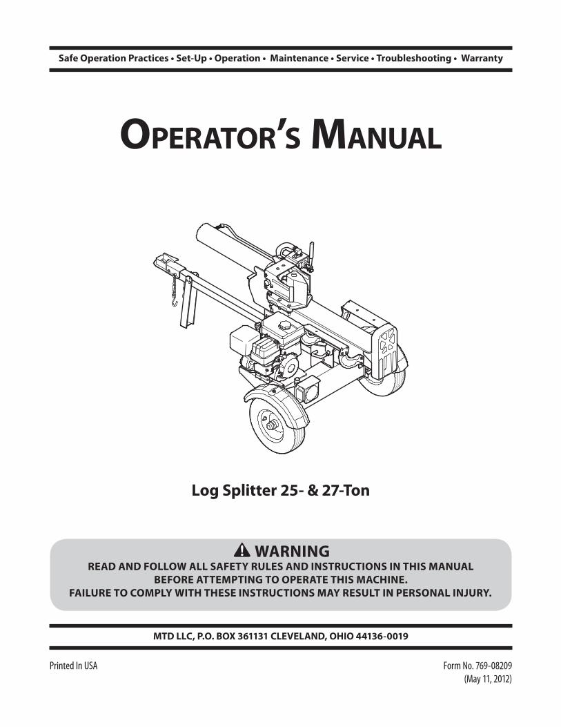
WARNINGREAD AND FOLLOW ALL SAFETY RULES AND INSTRUCTIONS IN THIS MANUAL
BEFORE ATTEMPTING TO OPERATE THIS MACHINE. FAILURE TO COMPLY WITH THESE INSTRUCTIONS MAY RESULT IN PERSONAL INJURY.
OperatOr’s Manual
Log Splitter 25- & 27-Ton
Form No. 769-08209 (May 11, 2012)
To The Owner 1
2
Safe Operation Practices ........................................ 3Assembly & Set-Up .................................................. 7Controls & Features ................................................11Operation ................................................................12Maintenance & Adjustment .................................15
Service .....................................................................17Troubleshooting .....................................................18Replacement Parts ................................................ 20Warranty ................................................................ 24
Table of Contents
Customer SupportPlease do NOT return the machine to the retailer or dealer without first contacting the Customer Support Department.
If you have difficulty assembling this product or have any questions regarding the controls, operation, or maintenance of this machine, you can seek help from the experts. Choose from the options below:
◊ Visit us on the web at www.mtdproducts..com
See How-to Maintenance and Parts Installation Videos at www.mtdparts.com/KnowledgeCenter
◊ Call a Customer Support Representative at (800) 800-7310 or (330) 220-4683
◊ Write to MTD LLC • P.O. Box 361131 • Cleveland, OH • 44136-0019
Thank you for purchasing an MTD Log Splitter. It was carefully engineered to provide excellent performance when properly operated and maintained.
Please read this entire manual prior to operating the equipment. It instructs you how to safely and easily set up, operate and maintain your machine. Please be sure that you, and any other persons who will operate the machine, carefully follow the recommended safety practices at all times. Failure to do so could result in personal injury or property damage.
All information in this manual is relative to the most recent product information available at the time of printing. Review this manual frequently to familiarize yourself with the machine, its features and operation. Please be aware that this Operator’s Manual may cover a range of product specifications for various models. Characteristics and features discussed and/or illustrated in this manual may not be applicable to all models. We reserve the right to change product specifications, designs and equipment without notice and without incurring obligation.
If applicable, the power testing information used to establish the power rating of the engine equipped on this machine can be found at www.opei.org or the engine manufacturer’s web site.
If you have any problems or questions concerning the machine, phone your local authorized MTD service dealer or contact us directly. MTD’s Customer Support telephone numbers, website address and mailing address can be found on this page. We want to ensure your complete satisfaction at all times.
Throughout this manual, all references to right and left side of the machine are observed from the operating position
Thank You
Record Product InformationBefore setting up and operating your new equipment, please locate the model plate on the equipment and record the information in the provided area to the right. You can locate the model plate by looking at the side flange of the engine mounting plate. This information will be necessary, should you seek technical support via our web site, Customer Support Department, or with a local authorized service dealer.
Model NuMber
Serial NuMber
Important Safe Operation Practices 2
3
Training1. Read, understand, and follow all instructions on the
machine and in the manual(s) before attempting to assemble and operate. Keep this manual in a safe place for future and regular reference and for ordering replacement parts.
2. Be familiar with all controls and their proper operation. Know how to stop the machine and disengage them quickly.
3. Never allow children under 16 years of age to operate this machine. Children 16 and over should read and understand the instructions and safe operation practices in this manual and on the machine and be trained and supervised by an adult.
4. Never allow adults to operate this machine without proper instruction.
5. Many accidents occur when more than one person operates the machine. If a helper is assisting in stacking logs, never activate the control until the helper is a minimum of 10 feet from the machine.
6. Keep bystanders, pets, and children at least 10 feet from the machine while it is in operation.
7. Never allow anyone to ride on this machine.
8. Never transport cargo on this machine.
9. Hydraulic log splitters develop high fluid pressures during operation. Fluid escaping through a pin hole opening can penetrate your skin and cause blood poisoning, gangrene, or death. Give attention to the following instructions at all times:
a. Do not check for leaks with your hand.
b. Do not operate machine with frayed, kinked, cracked, or damaged hoses, fittings, or tubing.
c. Stop the engine and relieve hydraulic system pressure by cycling the valve control lever from forward to reverse several times while engine is not running; returning to neutral before repairing or adjusting fittings, hoses, tubing, or other system components.
d. Do not adjust the pressure settings of the pump or valve.
10. Leaks can be detected by passing cardboard or wood, while wearing protective gloves and safety glasses, over the suspected area. Look for discoloration of cardboard or wood.
11. If injured by escaping fluid, see a doctor immediately. Serious infection or reaction can develop if proper medical treatment is not administered immediately.
12. Keep the operator zone and adjacent area clear for safe, secure footing.
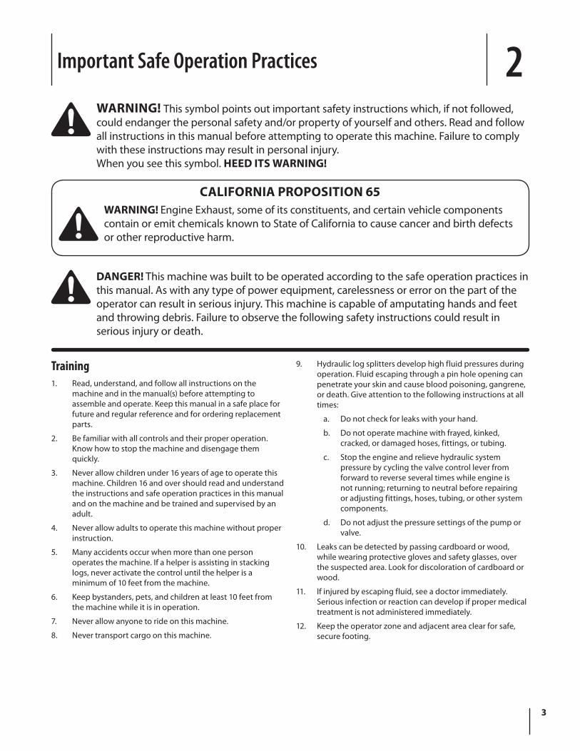
WARNING! This symbol points out important safety instructions which, if not followed, could endanger the personal safety and/or property of yourself and others. Read and follow all instructions in this manual before attempting to operate this machine. Failure to comply with these instructions may result in personal injury. When you see this symbol. HEED ITS WARNING!
DANGER! This machine was built to be operated according to the safe operation practices in this manual. As with any type of power equipment, carelessness or error on the part of the operator can result in serious injury. This machine is capable of amputating hands and feet and throwing debris. Failure to observe the following safety instructions could result in serious injury or death.
CALIFORNIA PROPOSITION 65WARNING! Engine Exhaust, some of its constituents, and certain vehicle components contain or emit chemicals known to State of California to cause cancer and birth defects or other reproductive harm.
4 Section 2 — important Safe operation practiceS
13. If your machine is equipped with an internal combustion engine and is intended for use near any unimproved forest, brush, or grass covered land, the engine exhaust should be equipped with a spark arrestor. Make sure you comply with applicable local, state, and federal codes. Take appropriate firefighting equipment with you.
14. This machine should be used for splitting wood only, do not use it for any other purpose.
15. Follow the instructions in the manual(s) provided with any attachment(s) for this machine.
Preparation 1. Always wear safety shoes or heavy boots.
2. Always wear safety glasses or safety goggles when operating this machine.
3. Never wear jewelry or loose clothing that might become entangled in moving or rotating parts of the machine.
4. Make sure machine is on a flat, dry, solid ground before operating.
5. Always block wheels to prevent unintended movement, and lock beam in either the horizontal or vertical position.
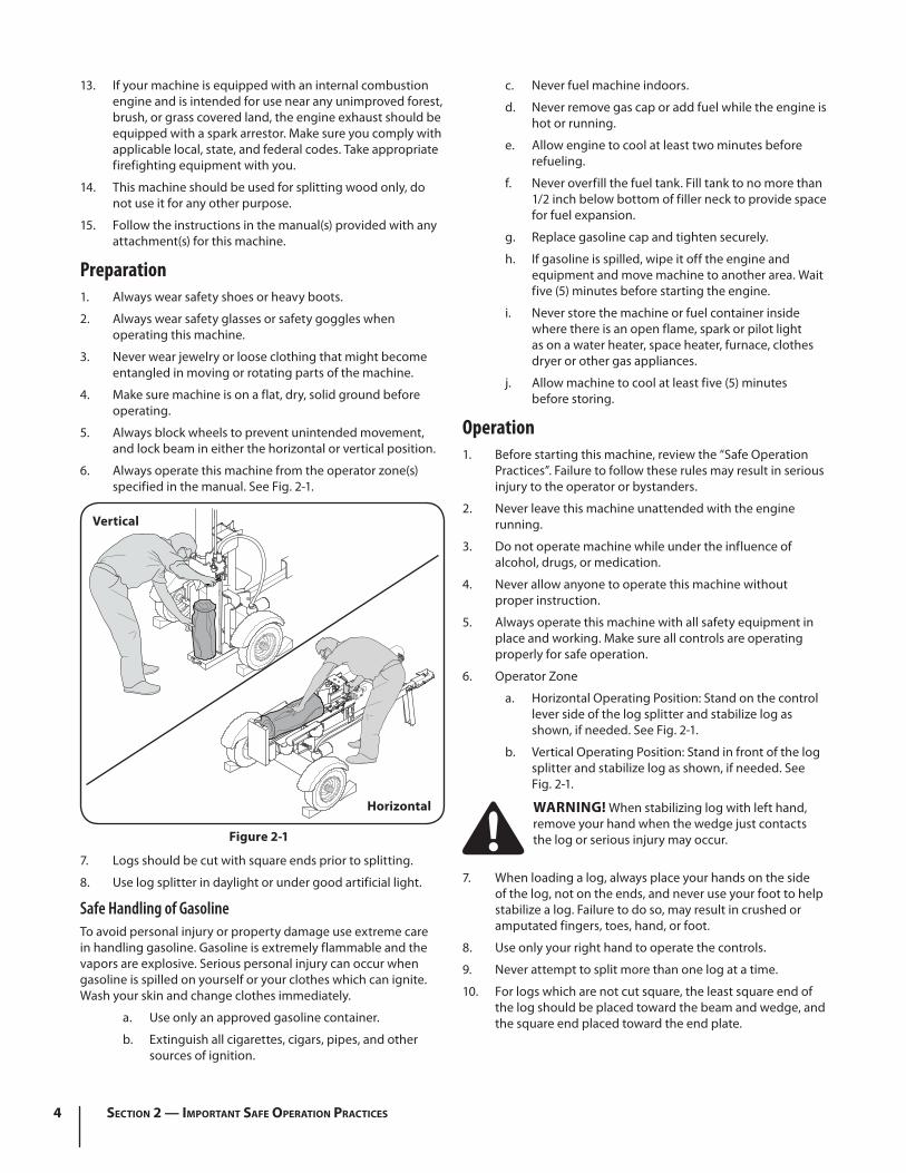
6. Always operate this machine from the operator zone(s) specified in the manual. See Fig. 2-1.
7. Logs should be cut with square ends prior to splitting.
8. Use log splitter in daylight or under good artificial light.
Safe Handling of Gasoline To avoid personal injury or property damage use extreme care in handling gasoline. Gasoline is extremely flammable and the vapors are explosive. Serious personal injury can occur when gasoline is spilled on yourself or your clothes which can ignite. Wash your skin and change clothes immediately.
a. Use only an approved gasoline container.
b. Extinguish all cigarettes, cigars, pipes, and other sources of ignition.
c. Never fuel machine indoors.
d. Never remove gas cap or add fuel while the engine is hot or running.
e. Allow engine to cool at least two minutes before refueling.
f. Never overfill the fuel tank. Fill tank to no more than 1/2 inch below bottom of filler neck to provide space for fuel expansion.
g. Replace gasoline cap and tighten securely.
h. If gasoline is spilled, wipe it off the engine and equipment and move machine to another area. Wait five (5) minutes before starting the engine.
i. Never store the machine or fuel container inside where there is an open flame, spark or pilot light as on a water heater, space heater, furnace, clothes dryer or other gas appliances.
j. Allow machine to cool at least five (5) minutes before storing.
Operation1. Before starting this machine, review the “Safe Operation
Practices”. Failure to follow these rules may result in serious injury to the operator or bystanders.
2. Never leave this machine unattended with the engine running.
3. Do not operate machine while under the influence of alcohol, drugs, or medication.
4. Never allow anyone to operate this machine without proper instruction.
5. Always operate this machine with all safety equipment in place and working. Make sure all controls are operating properly for safe operation.
6. Operator Zone
a. Horizontal Operating Position: Stand on the control lever side of the log splitter and stabilize log as shown, if needed. See Fig. 2-1.
b. Vertical Operating Position: Stand in front of the log splitter and stabilize log as shown, if needed. See Fig. 2-1.
WARNING! When stabilizing log with left hand, remove your hand when the wedge just contacts the log or serious injury may occur.
7. When loading a log, always place your hands on the side of the log, not on the ends, and never use your foot to help stabilize a log. Failure to do so, may result in crushed or amputated fingers, toes, hand, or foot.
8. Use only your right hand to operate the controls.
9. Never attempt to split more than one log at a time.
10. For logs which are not cut square, the least square end of the log should be placed toward the beam and wedge, and the square end placed toward the end plate.
Horizontal
Vertical
Figure 2-1
5Section 2 — important Safe operation practiceS
11. When splitting in the vertical position, stabilize the log before moving the control handle. Split as follows:
a. Place log on the end plate and turn until it leans against the beam and is stable.
b. When splitting extra large or uneven logs, the log must be stabilized with wooden shims or split wood placed between the log and end plate or ground.
12. Always keep fingers away from any cracks that open in the log while splitting. They can quickly close and pinch or amputate your fingers.
13. Keep your work area clean. Immediately remove split wood around the machine so you do not stumble over it.
14. Do not change the engine governor settings or overspeed the engine. The governor controls the maximum safe operating speed of the engine.
15. Never move this machine while the engine is running.
16. This machine should not be towed on any street, highway or public road without checking the existing federal, state, or local vehicle requirements. Any licensing or modifications such as taillights, etc., needed to comply, is the sole responsibility of the purchaser. If a “Statement of Origin” is required in your state, see your local dealer.
17. Do not tow machine over 45 mph.
18. See Transporting the Log Splitter section in this manual for proper towing instructions once all federal, local, or state requirements are met.
Maintenance and Storage1. Stop the engine, disconnect the spark plug and ground
it against the engine before cleaning, or inspecting the machine.
2. Stop the engine and relieve hydraulic system pressure by cycling the valve control lever from forward to reverse several times while engine is not running; returning to neutral before repairing or adjusting fittings, hoses, tubing, or other system components.
3. To prevent fires, clean debris and chaff from the engine and muffler areas. If the engine is equipped with a spark arrestor muffler, clean and inspect it regularly according to manufacturers instructions. Replace if damaged.
4. Periodically check that all nuts and bolts, hose clamps, and hydraulic fittings are tight to be sure equipment is in safe working condition.
5. Check all safety guards and shields to be sure they are in the proper position. Never operate with safety guards, shields, or other protective features removed.
6. The pressure relief valve is preset at the factory. Do not adjust the valve.
7. Never attempt to move this machine over hilly or uneven terrain without a tow vehicle or adequate help.
8. For your safety, replace all damaged or worn parts immediately with original equipment manufacturer’s (O.E.M.) parts only. Use of parts which do not meet the original equipment specifications may lead to improper performance and compromise safety!
9. Do not alter this machine in any manner, alterations such as attaching a rope or extension to the control handle, or adding to the width or height of the wedge may result in personal injury.
10. According to the Consumer Products Safety Commission (CPSC) and the U.S. Environmental Protection Agency (EPA), this product has an Average Useful Life of seven (7) years, or 130 hours of operation. At the end of the Average Useful Life have the machine inspected annually by an authorized service dealer to ensure that all mechanical and safety systems are working properly and not worn excessively. Failure to do so can result in accidents, injuries or death.
Spark ArrestorWARNING! This machine is equipped with an internal combustion engine and should not be used on or near any unimproved forest-covered, brush covered or grass-covered land unless the engine’s exhaust system is equipped with a spark arrestor meeting applicable local or state laws (if any).
If a spark arrestor is used, it should be maintained in effective working order by the operator. In the State of California the above is required by law (Section 4442 of the California Public Resources Code). Other states may have similar laws. Federal laws apply on federal lands. A spark arrestor for the muffler is available through your nearest engine authorized service dealer or contact the service department, P.O. Box 361131 Cleveland, Ohio 44136-0019.

6 Section 2 — important Safe operation practiceS
Safety SymbolsThis page depicts and describes safety symbols that may appear on this product. Read, understand, and follow all instructions on the machine before attempting to assemble and operate.
Symbol Description
READ THE OPERATOR’S MANUAL(S) Read, understand, and follow all instructions in the manual(s) before attempting to assemble and operate
WARNING— CRUSHING HAZARD Keep hands away from wedge, end plate, partially split wood and moving parts.
BYSTANDERS Keep bystanders, helpers and children at least 10 feet away.
SINGLE OPERATOR Only one person should operate the machine at a time. The adult who loads and stabilizes the log must be the person who operates control handle.
WARNING— PRESSURIZED FLUID Never check for hose leaks with your hands. High pressure fluid can escape through a pin hole leak and cause serious injury by puncturing the skin and causing blood poisoning.
EYE PROTECTION Always wear safety glasses or safety goggles when operating this machine.
WARNING— MOVING WEDGE Keep hands away from wedge and moving parts.
WARNING—GASOLINE IS FLAMMABLE Allow the engine to cool at least two minutes before refueling.
WARNING— CARBON MONOXIDENever run an engine indoors or in a poorly ventilated area. Engine exhaust contains carbon monoxide, an odorless and deadly gas.
WARNING— HOT SURFACE Engine parts, especially the muffler, become extremely hot during operation. Allow engine and muffler to cool before touching.
WARNING! Your Responsibility—Restrict the use of this power machine to persons who read, understand and follow the warnings and instructions in this manual and on the machine.
SAVE THESE INSTRUCTIONS!
Assembly & Set-Up 3
7
Contents of Carton• One Log Splitter • One Tongue Assembly • One Operator’s Manual
• One Engine Operator’s Manual • One Light Kit (If equipped)
WARNING! Use extreme caution unpacking this machine. Some components are very heavy and will require additional people or mechanical handling equipment.
NOTE: All references in this manual to the left or right side and front or back of the log splitter are from the operating position only. Exceptions, if any, will be specified.
Unpacking & Assembling the Log SplitterTOOLS NEEDED: Safety glasses, leather gloves, wire cutters, pry bar and/or claw hammer.
1. Use a pry bar or claw hammer to loosen and remove the top of the crate.
2. Use a pry bar or claw hammer to remove the sides of the crate, beginning with the short sides (or left and right side of the log splitter). Set the sides of the crate aside to avoid injury.
3. On the front side of the crate the tongue assembly is attached on the inside of the crate with a cable tie. Cut the cable tie to remove the tongue.
4. Remove the large plastic cover and discard.
WARNING! Do NOT remove any wood or cut any straps securing the log splitter or its components to the log splitter or the crate at this time. Only remove straps and/or wood when instructed to do so.
5. Inspect the bottom of the crate for any protruding staples or wood splinters and remove.
6. Remove any loose parts included with the log splitter (i.e. operator’s manual, tail light kit, etc.).
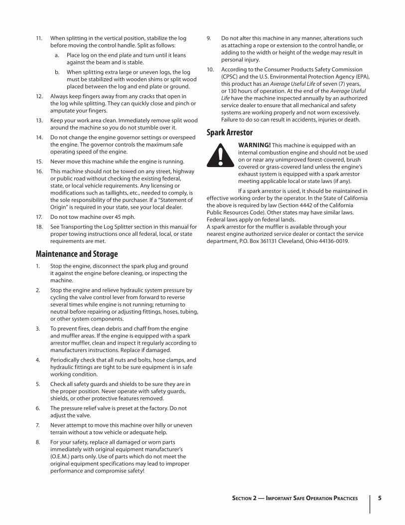
7. Remove the spring clip and clevis pin from the jack stand on the tongue and then pivot the jack stand towards the ground into the operating position. See Fig. 3-1.
Spring Clip
Clevis Pin
Jack Stand
Figure 1-1
8. Secure the jack stand in position with the clevis pin and spring clip. See Fig. 3-1.
9. With the log splitter still secured to the bottom of the crate, remove two hex bolts and hex nuts from the tank bracket and remove the piece of wood inside the tank brackets. See Fig. 3-2.
Hex Nuts
Hex Bolts
Tongue
Tank Brackets
Figure 1-2
8 Section 2— ASSembly & Set-Up
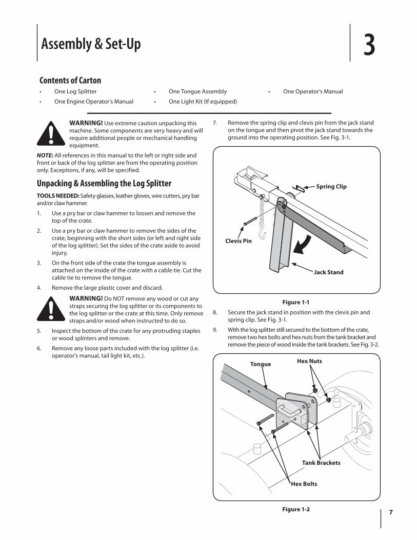
14. Disconnect the dislodger from the beam weld bracket by removing the six hex screws. See Fig. 3-4.
Hex Screws
Hex Screws
Dislodger
Figure 1-4
15. Disconnect the log tray from the beam on the side of the control valve by removing the two hex washer screws that secure it to the beam and the two hex washer screws in the beam. See Fig. 3-5.
Hex WasherScrew
Log Tray
Beam
Figure 1-5
10. Align the holes in the tongue with the holes in the tank bracket and secure with the hardware just removed. See Fig. 3-2.
NOTE: The high pressure hose, which runs from the gear pump to the bottom of the control valve, must be above the tongue assembly.
11. The log splitter is shipped with the beam in a vertical position. Remove any bolts or straps securing the end plate to the bottom of the crate.
12. Pull out the vertical beam lock, rotate it back, and pivot the beam to the horizontal position until it locks being sure to avoid any possible pinch points. See Fig. 3-3.
Vertical Beam Lock
Figure 1-3
WARNING! Take extra care when raising and lowering the beam as it is fairly heavy. Having a second person assist with raising or lowering the beam is recommended. Be sure to keep hands away from any possible pinch points.
13. Remove the wood between the wedge and the end plate by cutting the cable tie that secures it. Cut the strap near the hose on the front of the cylinder that secures it to the beam weld bracket. Be careful not to damage the hose.
9Section 2 — ASSembly & Set-Up
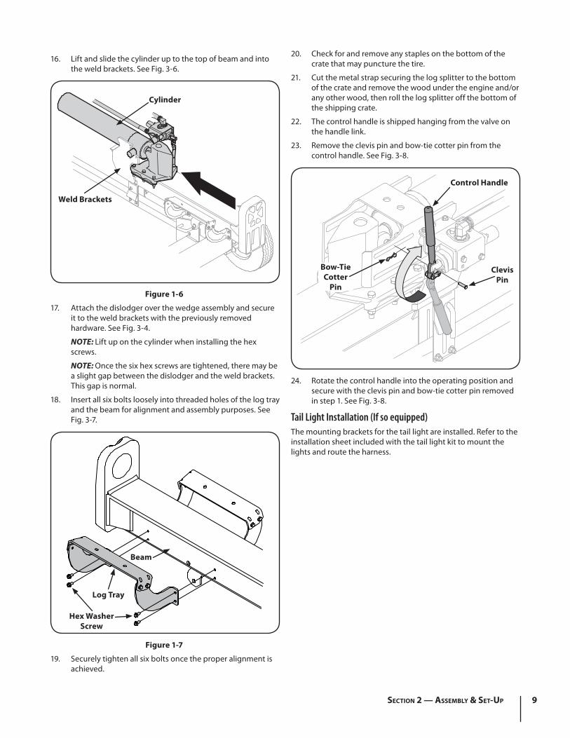
16. Lift and slide the cylinder up to the top of beam and into the weld brackets. See Fig. 3-6.
Cylinder
Weld Brackets
Figure 1-6
17. Attach the dislodger over the wedge assembly and secure it to the weld brackets with the previously removed hardware. See Fig. 3-4.
NOTE: Lift up on the cylinder when installing the hex screws.
NOTE: Once the six hex screws are tightened, there may be a slight gap between the dislodger and the weld brackets. This gap is normal.
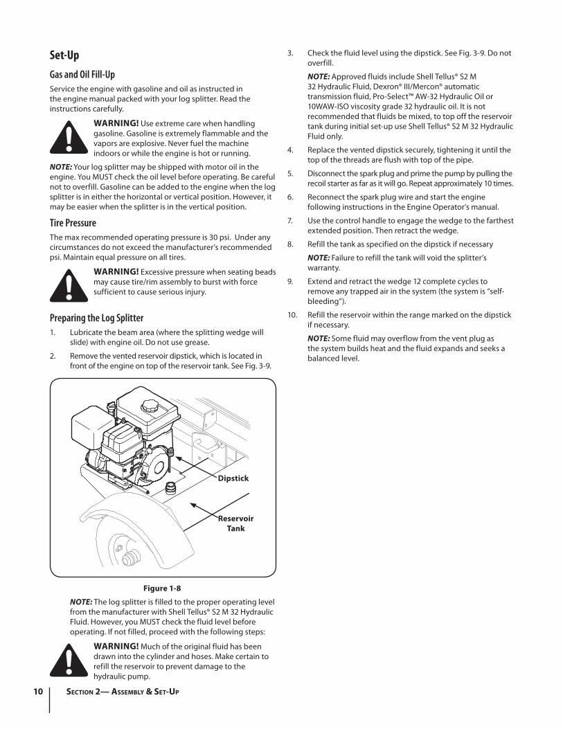
18. Insert all six bolts loosely into threaded holes of the log tray and the beam for alignment and assembly purposes. See Fig. 3-7.
Hex WasherScrew
Log Tray
Beam
Figure 1-7
19. Securely tighten all six bolts once the proper alignment is achieved.
20. Check for and remove any staples on the bottom of the crate that may puncture the tire.
21. Cut the metal strap securing the log splitter to the bottom of the crate and remove the wood under the engine and/or any other wood, then roll the log splitter off the bottom of the shipping crate.
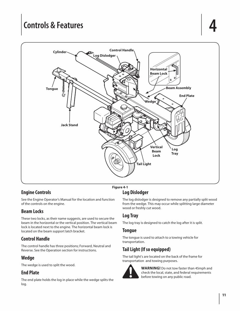
22. The control handle is shipped hanging from the valve on the handle link.
23. Remove the clevis pin and bow-tie cotter pin from the control handle. See Fig. 3-8.
Bow-TieCotter
Pin
Control Handle
ClevisPin
24. Rotate the control handle into the operating position and secure with the clevis pin and bow-tie cotter pin removed in step 1. See Fig. 3-8.
Tail Light Installation (If so equipped)The mounting brackets for the tail light are installed. Refer to the installation sheet included with the tail light kit to mount the lights and route the harness.
10 Section 2— ASSembly & Set-Up
3. Check the fluid level using the dipstick. See Fig. 3-9. Do not overfill.
NOTE: Approved fluids include Shell Tellus® S2 M 32 Hydraulic Fluid, Dexron® III/Mercon® automatic transmission fluid, Pro-Select™ AW-32 Hydraulic Oil or 10WAW-ISO viscosity grade 32 hydraulic oil. It is not recommended that fluids be mixed, to top off the reservoir tank during initial set-up use Shell Tellus® S2 M 32 Hydraulic Fluid only.
4. Replace the vented dipstick securely, tightening it until the top of the threads are flush with top of the pipe.
5. Disconnect the spark plug and prime the pump by pulling the recoil starter as far as it will go. Repeat approximately 10 times.
6. Reconnect the spark plug wire and start the engine following instructions in the Engine Operator’s manual.
7. Use the control handle to engage the wedge to the farthest extended position. Then retract the wedge.
8. Refill the tank as specified on the dipstick if necessary
NOTE: Failure to refill the tank will void the splitter’s warranty.
9. Extend and retract the wedge 12 complete cycles to remove any trapped air in the system (the system is “self-bleeding”).
10. Refill the reservoir within the range marked on the dipstick if necessary.
NOTE: Some fluid may overflow from the vent plug as the system builds heat and the fluid expands and seeks a balanced level.
Set-UpGas and Oil Fill-UpService the engine with gasoline and oil as instructed in the engine manual packed with your log splitter. Read the instructions carefully.
WARNING! Use extreme care when handling gasoline. Gasoline is extremely flammable and the vapors are explosive. Never fuel the machine indoors or while the engine is hot or running.
NOTE: Your log splitter may be shipped with motor oil in the engine. You MUST check the oil level before operating. Be careful not to overfill. Gasoline can be added to the engine when the log splitter is in either the horizontal or vertical position. However, it may be easier when the splitter is in the vertical position.
Tire PressureThe max recommended operating pressure is 30 psi. Under any circumstances do not exceed the manufacturer’s recommended psi. Maintain equal pressure on all tires.
WARNING! Excessive pressure when seating beads may cause tire/rim assembly to burst with force sufficient to cause serious injury.
Preparing the Log Splitter1. Lubricate the beam area (where the splitting wedge will
slide) with engine oil. Do not use grease.
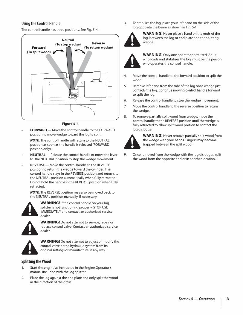
2. Remove the vented reservoir dipstick, which is located in front of the engine on top of the reservoir tank. See Fig. 3-9.
Dipstick
ReservoirTank
Figure 1-8
NOTE: The log splitter is filled to the proper operating level from the manufacturer with Shell Tellus® S2 M 32 Hydraulic Fluid. However, you MUST check the fluid level before operating. If not filled, proceed with the following steps:
WARNING! Much of the original fluid has been drawn into the cylinder and hoses. Make certain to refill the reservoir to prevent damage to the hydraulic pump.
Controls & Features 4
11
CylinderLog Dislodger
Control Handle
Wedge
Beam Assembly
LogTray
VerticalBeamLock
Jack Stand
Tongue
HorizontalBeam Lock
End Plate
Tail Light
Figure 4-1
Engine ControlsSee the Engine Operator’s Manual for the location and function of the controls on the engine.
Beam LocksThese two locks, as their name suggests, are used to secure the beam in the horizontal or the vertical position. The vertical beam lock is located next to the engine. The horizontal beam lock is located on the beam support latch bracket.
Control HandleThe control handle has three positions; Forward, Neutral and Reverse. See the Operation section for instructions.
WedgeThe wedge is used to split the wood.
End PlateThe end plate holds the log in place while the wedge splits the log.
Log DislodgerThe log dislodger is designed to remove any partially split wood from the wedge. This may occur while splitting large diameter wood or freshly cut wood.
Log TrayThe log tray is designed to catch the log after it is split.
TongueThe tongue is used to attach to a towing vehicle for transportation.
Tail Light (If so equipped)The tail light’s are located on the back of the frame for transportation and towing purposes.
WARNING! Do not tow faster than 45mph and check the local, state, and federal requirements before towing on any public road.

Operation 5
12
Starting & Stopping the EngineRefer to the Engine Operator’s manual packed with your log splitter for instructions on starting and stopping the engine.
Using the Log SplitterOperating Positions1. Place the log splitter on flat, dry, solid ground.
2. Block the front and back of both wheels. See Fig. 5-1.
3. Place the beam in either the horizontal or vertical position and lock into place.
WARNING! Take extra care when raising and lowering the beam as it is fairly heavy. Having a second person assist with raising or lowering the beam is recommended. Be sure to keep hands away from any possible pinch points.
4. To place the beam in the Vertical Position proceed as follows:
WARNING! Always use the log splitter in the vertical position when splitting heavy logs.
a. Pull the horizontal beam lock out to release the beam and pivot the beam to the vertical position.
b. To lock the beam in the vertical position, pull out on the vertical beam lock and rotate it to secure the beam. See Fig. 5-2.
5. To place the beam in the Horizontal Position proceed as follows:
a. Pull the vertical beam lock out and rotate it down. Pivot the beam to the horizontal position.
b. The horizontal beam lock is self-locking. The spring loaded lock will snap into place when the beam is lowered into position. See Fig. 5-3.
Vertical Beam Lock
1
2
Figure 5-2
Horizontal
Vertical
Figure 5-1
1
2
Horizontal Beam Lock
Figure 5-3
13Section 5 — operation
Using the Control HandleThe control handle has three positions. See Fig. 5-4.
• FORWARD — Move the control handle to the FORWARD position to move wedge toward the log to split.
NOTE: The control handle will return to the NEUTRAL position as soon as the handle is released (FORWARD position only).
• NEUTRAL — Release the control handle or move the lever to the NEUTRAL position to stop the wedge movement.
• REVERSE — Move the control handle to the REVERSE position to return the wedge toward the cylinder. The control handle stays in the REVERSE position and returns to the NEUTRAL position automatically when fully retracted. Do not hold the handle in the REVERSE position when fully retracted.
NOTE: The REVERSE position may also be moved back to the NEUTRAL position manually, if necessary.
WARNING! If the control handle on your log splitter is not functioning properly, STOP USE IMMEDIATELY and contact an authorized service dealer.
WARNING! Do not attempt to service, repair or replace control valve. Contact an authorized service dealer.
WARNING! Do not attempt to adjust or modify the control valve or the hydraulic system from its original settings or manufacture in any way.
Splitting the Wood1. Start the engine as instructed in the Engine Operator’s
manual included with the log splitter.
2. Place the log against the end plate and only split the wood in the direction of the grain.
3. To stabilize the log, place your left hand on the side of the log opposite the beam as shown in Fig. 5-1.
WARNING! Never place a hand on the ends of the log, between the log or end plate and the splitting wedge.
WARNING! Only one operator permitted. Adult who loads and stabilizes the log, must be the person who operates the control handle.
4. Move the control handle to the forward position to split the wood.
5. Remove left hand from the side of the log once wedge just contacts the log. Continue moving control handle forward to split the log.
6. Release the control handle to stop the wedge movement.
7. Move the control handle to the reverse position to return the wedge.
8. To remove partially split wood from wedge, move the control handle to the REVERSE position until the wedge is fully retracted to allow split wood portion to contact the log dislodger.
WARNING! Never remove partially split wood from the wedge with your hands. Fingers may become trapped between the split wood.
9. Once removed from the wedge with the log dislodger, split the wood from the opposite end or in another location.
Neutral(To stop wedge)
Forward(To split wood)
Reverse(To return wedge)
Figure 5-4
14 Section 5— operation
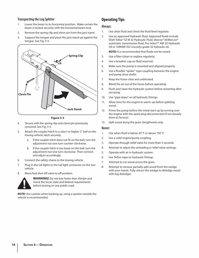
Transporting the Log Splitter1. Lower the beam to its horizontal position. Make certain the
beam is locked securely with the horizontal beam lock.
2. Remove the spring clip and clevis pin from the jack stand.
3. Support the tongue and pivot the jack stand up against the tongue. See Fig. 5-5.
4. Secure with the spring clip and clevis pin previously removed. See Fig. 5-5.
5. Attach the coupler hitch to a class I or higher 2” ball on the towing vehicle; latch securely.
a. If the coupler hitch does not fit on the ball, turn the adjustment nut one turn counter-clockwise.
b. If the coupler hitch is too loose on the ball, turn the adjustment nut one turn clockwise. Then recheck and adjust accordingly.
6. Connect the safety chains to the towing vehicle.
7. Plug in the tail lights to the tail light connector on the tow vehicle.
8. Move fuel shut-off valve to off position.
WARNING! Do not tow faster than 45mph and check the local, state and federal requirements before towing on any public road.
NOTE: Use caution when backing up, using a spotter outside the vehicle is recommended.
Operating TipsAlways:1. Use clean fluid and check the fluid level regularly.
2. Use an approved hydraulic fluid. Approved fluids include Shell Tellus® S2 M 32 Hydraulic Fluid, Dexron® III/Mercon® automatic transmission fluid, Pro-Select™ AW-32 Hydraulic Oil or 10WAW-ISO viscosity grade 32 hydraulic oil.
NOTE: It is recommended that fluids not be mixed.
3. Use a filter (clean or replace regularly).
4. Use a breather cap on fluid reservoir.
5. Make sure the pump is mounted and aligned properly.
6. Use a flexible “spider” type coupling between the engine and pump drive shafts.
7. Keep the hoses clear and unblocked.
8. Bleed the air out of the hoses before operating.
9. Flush and clean the hydraulic system before restarting after servicing.
10. Use “pipe dope” on all hydraulic fittings.
11. Allow time for the engine to warm-up before splitting wood.
12. Prime the pump before the initial start-up by turning over the engine with the spark plug disconnected (if not already done at factory).
13. Split wood along the grain (lengthwise) only.
Never:1. Use when fluid is below 20° F or above 150° F.
2. Use a solid engine/pump coupling.
3. Operate through relief valve for more than 5 seconds.
4. Attempt to adjust the unloading or relief valve settings.
5. Operate with air in hydraulic system.
6. Use Teflon tape on hydraulic fittings.
7. Attempt to cut wood across the grain.
8. Attempt to remove partially split wood from the wedge with your hands. Fully retract the wedge to dislodge wood with log dislodger.
Spring Clip
Clevis Pin
Jack Stand
Figure 5-5
Maintenance & Adjustments 6
15
WARNING! Do not make any adjustments without stopping the engine, disconnecting the spark plug wire, grounding it against the engine and relieving the hydro system pressure. Always wear safety glasses during operation or while performing any adjustments or repairs.
EngineRefer to the Engine Operator’s Manual packed with your log splitter for all engine maintenance.
Tire PressureThe max recommended operating pressure is 30 psi. Do not, under any circumstances, exceed the manufacturer’s recommended psi. Maintain equal pressure on all tires.
WARNING! Excessive pressure when seating beads may cause the tire/rim assembly to burst with force sufficient to cause serious injury. Refer to the sidewall of the tire for recommended pressure.
Hydraulic FluidCheck the hydraulic fluid level in the log splitter reservoir tank before each use. Maintain the fluid level within the range specified on the dipstick at all times.
Change the hydraulic fluid in the reservoir every 100 hours of operation. The filter should also be changed with each hydraulic fluid change. Follow the steps below:
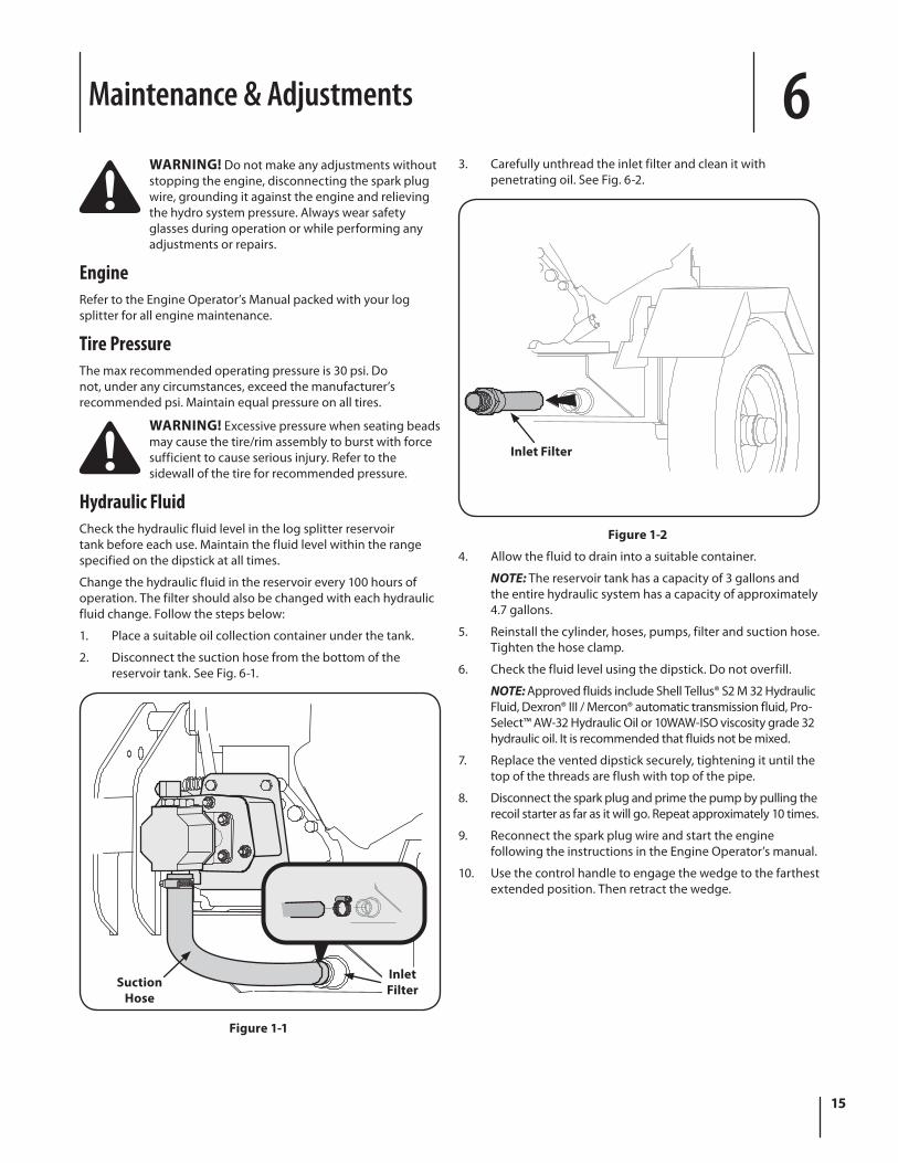
1. Place a suitable oil collection container under the tank.
2. Disconnect the suction hose from the bottom of the reservoir tank. See Fig. 6-1.
SuctionHose
InletFilter
Figure 1-1
3. Carefully unthread the inlet filter and clean it with penetrating oil. See Fig. 6-2.
Inlet Filter
Figure 1-2
4. Allow the fluid to drain into a suitable container.
NOTE: The reservoir tank has a capacity of 3 gallons and the entire hydraulic system has a capacity of approximately 4.7 gallons.
5. Reinstall the cylinder, hoses, pumps, filter and suction hose. Tighten the hose clamp.
6. Check the fluid level using the dipstick. Do not overfill.
NOTE: Approved fluids include Shell Tellus® S2 M 32 Hydraulic Fluid, Dexron® III / Mercon® automatic transmission fluid, Pro-Select™ AW-32 Hydraulic Oil or 10WAW-ISO viscosity grade 32 hydraulic oil. It is recommended that fluids not be mixed.
7. Replace the vented dipstick securely, tightening it until the top of the threads are flush with top of the pipe.
8. Disconnect the spark plug and prime the pump by pulling the recoil starter as far as it will go. Repeat approximately 10 times.
9. Reconnect the spark plug wire and start the engine following the instructions in the Engine Operator’s manual.
10. Use the control handle to engage the wedge to the farthest extended position. Then retract the wedge.
16 Section 6— Maintenance & adjuStMentS
BeamLubricate both sides of the beam (where it comes into contact with the splitting wedge), before each use, with engine oil.
Off-Season StorageIf the log splitter will not be used for more than 30 days, prepare it for storage as follows:
WARNING! Never store the machine with fuel in the fuel tank inside of building where fumes may reach an open flame or spark, or where ignition sources are present such as hot water and space heaters, furnaces, clothes dryers, stoves, electric motors, etc.
1. Refer to the Engine Operator’s manual packed with your log splitter for information on the off-season storage of the engine.
2. Clean the log splitter thoroughly.
NOTE: The use of pressure washers or a garden hose to clean the splitter is not recommended. They may cause damage to the bearings or the engine. The use of water will result in a shortened life and reduce serviceability.
3. Wipe the machine with an oiled rag to prevent rust, especially on the wedge and the beam.
4. Store the log splitter in a clean, dry area. Do not store it next to corrosive materials, such as fertilizer.
NOTE: If storing in an unventilated or metal storage shed, be certain to rustproof the equipment by coating it with a light oil or silicone.
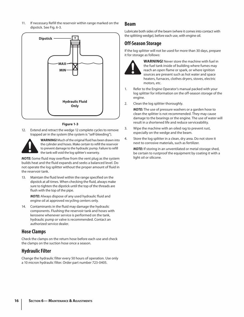
11. If necessary Refill the reservoir within range marked on the dipstick. See Fig. 6-3.
Dipstick
MAX
MIN
Hydraulic FluidOnly
Figure 1-3
12. Extend and retract the wedge 12 complete cycles to remove trapped air in the system (the system is “self-bleeding”).
WARNING! Much of the original fluid has been drawn into the cylinder and hoses. Make certain to refill the reservoir to prevent damage to the hydraulic pump. Failure to refill the tank will void the log splitter’s warranty.
NOTE: Some fluid may overflow from the vent plug as the system builds heat and the fluid expands and seeks a balanced level. Do not operate the log splitter without the proper amount of fluid in the reservoir tank.
13. Maintain the fluid level within the range specified on the dipstick at all times. When checking the fluid, always make sure to tighten the dipstick until the top of the threads are flush with the top of the pipe.
NOTE: Always dispose of any used hydraulic fluid and engine oil at approved recycling centers only.
14. Contaminants in the fluid may damage the hydraulic components. Flushing the reservoir tank and hoses with kerosene whenever service is performed on the tank, hydraulic pump or valve is recommended. Contact an authorized service dealer.
Hose ClampsCheck the clamps on the return hose before each use and check the clamps on the suction hose once a season.
Hydraulic FilterChange the hydraulic filter every 50 hours of operation. Use only a 10 micron hydraulic filter. Order part number 723-0405.
Service 7
17
Flexible Pump CouplerThe flexible pump coupler is a nylon “spider” insert, located between the pump and the engine shaft. Over time, the coupler will harden and deteriorate. Replace the coupler if you detect vibration or noise coming from the area between the engine and the pump. If the coupler fails completely, you will experience a loss of power.
NOTE: Never hit the engine shaft in any manner, as a blow will cause permanent damage to the engine.
1. Disconnect the spark plug wire and ground it against the engine.
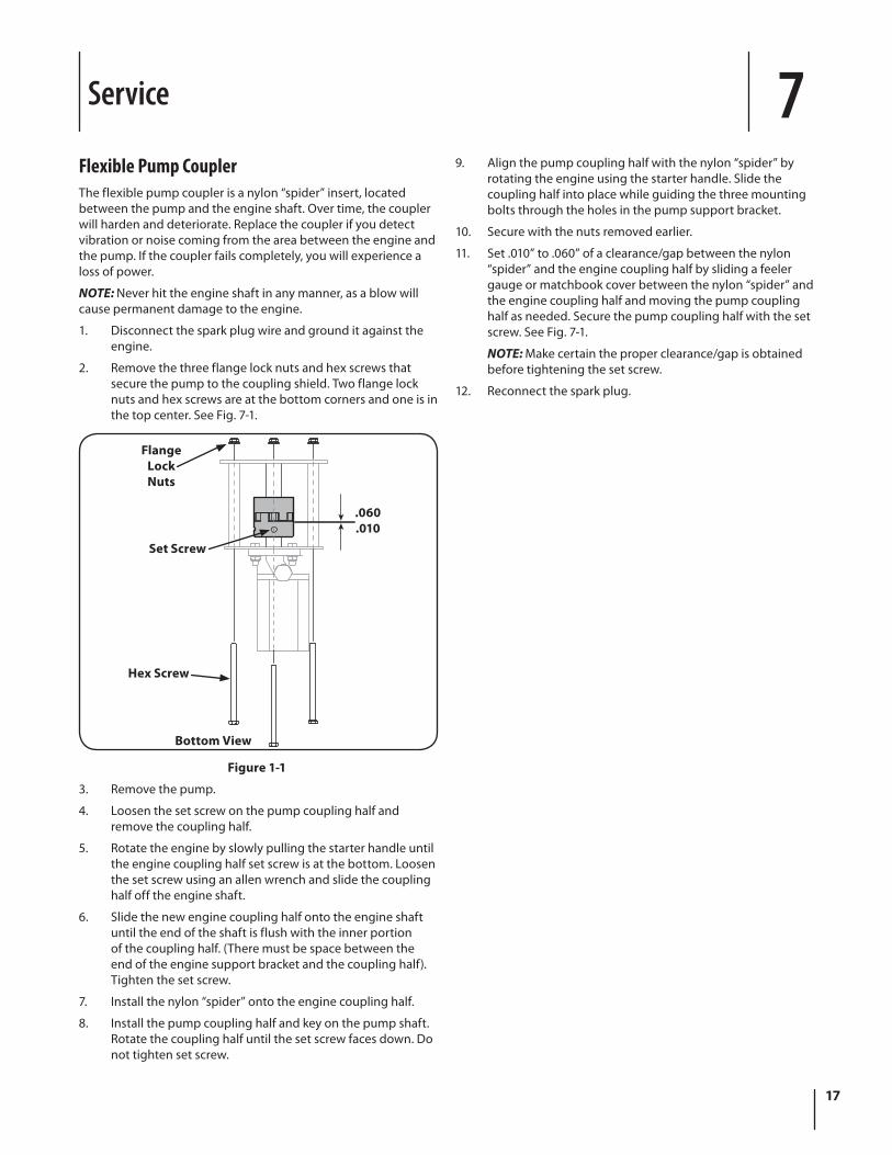
2. Remove the three flange lock nuts and hex screws that secure the pump to the coupling shield. Two flange lock nuts and hex screws are at the bottom corners and one is in the top center. See Fig. 7-1.
.060
.010
FlangeLockNuts
Hex Screw
Set Screw
Bottom View
Figure 1-1
3. Remove the pump.
4. Loosen the set screw on the pump coupling half and remove the coupling half.
5. Rotate the engine by slowly pulling the starter handle until the engine coupling half set screw is at the bottom. Loosen the set screw using an allen wrench and slide the coupling half off the engine shaft.
6. Slide the new engine coupling half onto the engine shaft until the end of the shaft is flush with the inner portion of the coupling half. (There must be space between the end of the engine support bracket and the coupling half). Tighten the set screw.
7. Install the nylon “spider” onto the engine coupling half.
8. Install the pump coupling half and key on the pump shaft. Rotate the coupling half until the set screw faces down. Do not tighten set screw.
9. Align the pump coupling half with the nylon “spider” by rotating the engine using the starter handle. Slide the coupling half into place while guiding the three mounting bolts through the holes in the pump support bracket.
10. Secure with the nuts removed earlier.
11. Set .010” to .060” of a clearance/gap between the nylon “spider” and the engine coupling half by sliding a feeler gauge or matchbook cover between the nylon “spider” and the engine coupling half and moving the pump coupling half as needed. Secure the pump coupling half with the set screw. See Fig. 7-1.
NOTE: Make certain the proper clearance/gap is obtained before tightening the set screw.
12. Reconnect the spark plug.

Troubleshooting 8
18
Problem Cause Remedy
Cylinder rod will not move 1. Broken drive shaft.
2. Shipping plugs left in hydraulic hoses.
3. Set screws in coupling not adjusted properly.
4. Loose shaft coupling.
5. Gear sections damaged.
6. Damaged relief valve.
7. Hydraulic lines blocked.
8. Incorrect oil level.
9. Damaged control valve.
10. Blocked control valve.
1. See authorized service dealer.
2. Disconnect hydraulic hoses, remove shipping plugs, reconnect hoses.
3. See authorized service dealer.
4. Correct engine/pump alignment as necessary.
5. See authorized service dealer.
6. See authorized service dealer.
7. Flush and clean hydraulic system.
8. Check oil level.
9. See authorized service dealer.
10. Flush and clean hydraulic system
Slow cylinder shaft speed while extending and retracting
1. Gear sections damaged.
2. Excessive pump inlet vacuum.
3. Slow engine speed.
4. Damaged relief valve.
5. Incorrect oil level.
6. Contaminated oil.
7. Control valve leaking internally.
8. Internally damaged cylinder.
1. See authorized service dealer.
2. Make certain pump inlet hoses are clear and unblocked. use short, large diameter inlet hoses.
3. See authorized service dealer.
4. See authorized service dealer.
5. Check oil level.
6. Drain oil, clean reservoir and refill.
7. See authorized service dealer.
8. See authorized service dealer
Leaking Cylinder 1. Worn seals.
2. Scored cylinder.
1. See authorized service dealer.
2. See authorized service dealer.
19Section 8 — troubleShooting
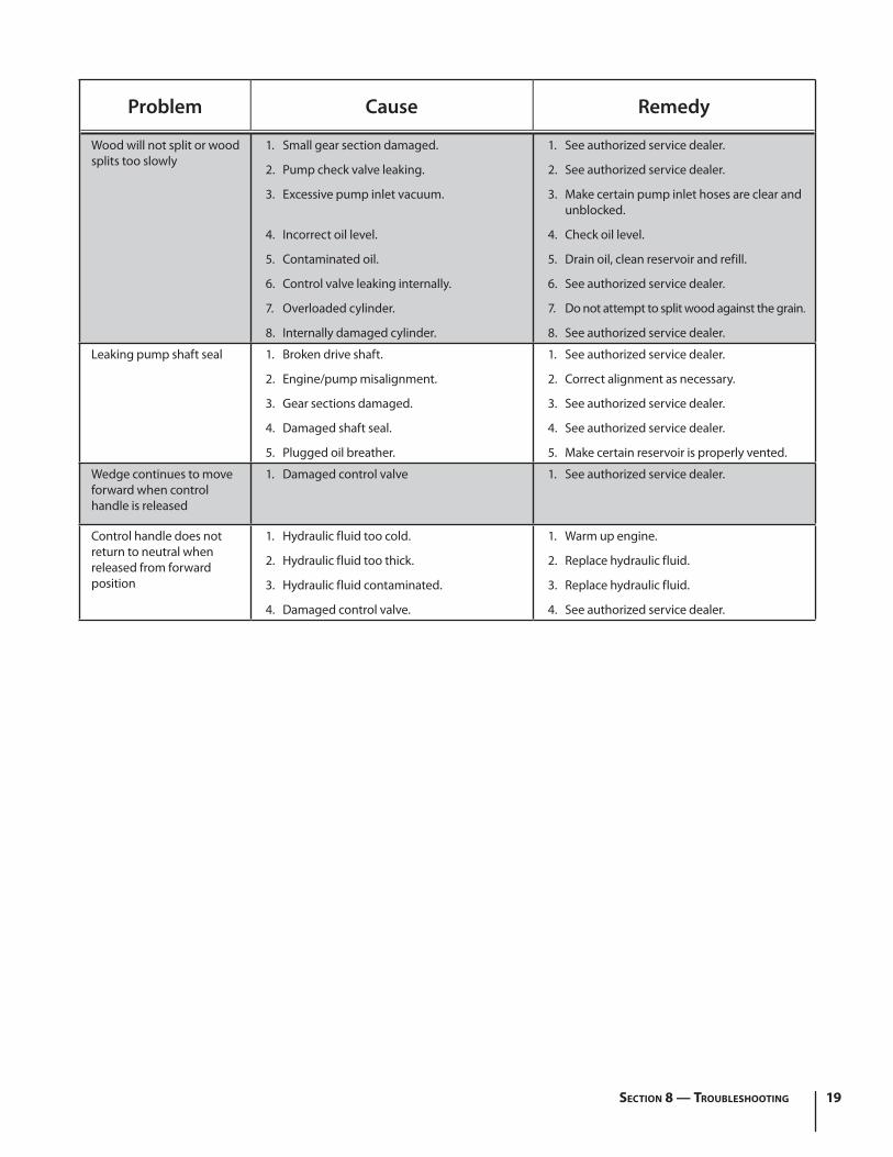
Problem Cause Remedy
Wood will not split or wood splits too slowly
1. Small gear section damaged.
2. Pump check valve leaking.
3. Excessive pump inlet vacuum.
4. Incorrect oil level.
5. Contaminated oil.
6. Control valve leaking internally.
7. Overloaded cylinder.
8. Internally damaged cylinder.
1. See authorized service dealer.
2. See authorized service dealer.
3. Make certain pump inlet hoses are clear and unblocked.
4. Check oil level.
5. Drain oil, clean reservoir and refill.
6. See authorized service dealer.
7. Do not attempt to split wood against the grain.
8. See authorized service dealer.
Leaking pump shaft seal 1. Broken drive shaft.
2. Engine/pump misalignment.
3. Gear sections damaged.
4. Damaged shaft seal.
5. Plugged oil breather.
1. See authorized service dealer.
2. Correct alignment as necessary.
3. See authorized service dealer.
4. See authorized service dealer.
5. Make certain reservoir is properly vented.
Wedge continues to move forward when control handle is released
1. Damaged control valve 1. See authorized service dealer.
Control handle does not return to neutral when released from forward position
1. Hydraulic fluid too cold.
2. Hydraulic fluid too thick.
3. Hydraulic fluid contaminated.
4. Damaged control valve.
1. Warm up engine.
2. Replace hydraulic fluid.
3. Replace hydraulic fluid.
4. See authorized service dealer.
Replacement Parts 9
20
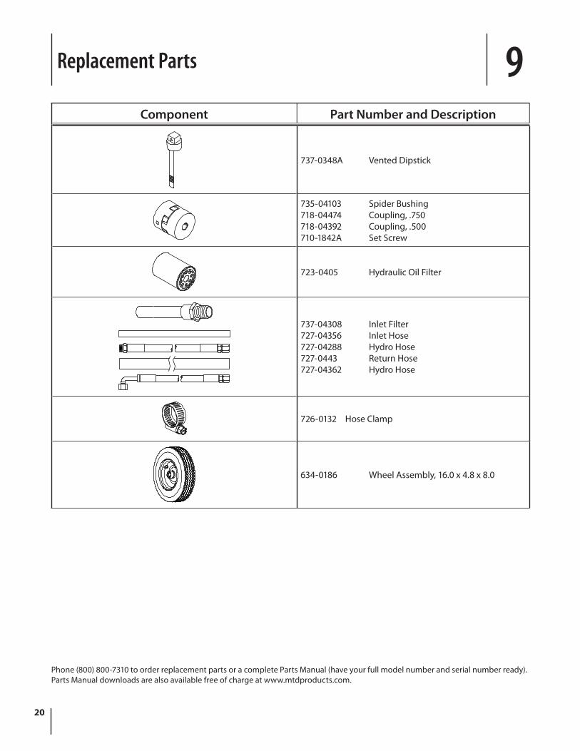
Component Part Number and Description
737-0348A Vented Dipstick
735-04103 Spider Bushing718-04474 Coupling, .750718-04392 Coupling, .500710-1842A Set Screw
723-0405 Hydraulic Oil Filter
737-04308 Inlet Filter727-04356 Inlet Hose727-04288 Hydro Hose727-0443 Return Hose727-04362 Hydro Hose
726-0132 Hose Clamp
634-0186 Wheel Assembly, 16.0 x 4.8 x 8.0
Phone (800) 800-7310 to order replacement parts or a complete Parts Manual (have your full model number and serial number ready). Parts Manual downloads are also available free of charge at www.mtdproducts.com.

Notes 9
21

22 Section 9— noteS

23Section 9 — noteS

MANUFACTURER’S LIMITED WARRANTY FOR
GDOC-100016 REV. C
The limited warranty set forth below is given by MTD LLC with respect to new merchandise purchased and used in the United States and/or its territories and possessions, and by MTD Products Limited with respect to new merchandise purchased and used in Canada and/or its territories and possessions (either entity respectively, “MTD”).
This warranty is in addition to any applicable emissions warranty provided with your product.
“MTD” warrants this product (excluding its Normal Wear Parts and Attachments as described below) against defects in material and workmanship for a period of two (2) years commencing on the date of original purchase and will, at its option, repair or replace, free of charge, any part found to be defective in materials or workmanship. This limited warranty shall only apply if this product has been operated and maintained in accordance with the Operator’s Manual furnished with the product, and has not been subject to misuse, abuse, commercial use, neglect, accident, improper maintenance, alteration, vandalism, theft, fire, water, or damage because of other peril or natural disaster. Damage resulting from the installation or use of any part, accessory or attachment not approved by MTD for use with the product(s) covered by this manual will void your warranty as to any resulting damage.
Normal Wear Parts are warranted to be free from defects in material and workmanship for a period of thirty (30) days from the date of purchase. Normal wear parts include, but are not limited to items such as: batteries, belts, blades, blade adapters, tines, grass bags, wheels, rider deck wheels, seats, snow thrower skid shoes, friction wheels, shave plates, auger spiral rubber, engine oil, air filters, spark plugs and tires.
Attachments — MTD warrants attachments for this product against defects in material and workmanship for a period of one (1) year, commencing on the date of the attachment’s original purchase or lease. Attachments include, but are not limited to items such as: grass collectors and mulch kits.
HOW TO OBTAIN PARTS AND SERVICE: Warranty service is available, WITH PROOF OF PURCHASE, through your local authorized service dealer. To locate the dealer in your area:
In the U.S.A.
Check your Yellow Pages, or contact MTD LLC at P.O. Box 361131, Cleveland, Ohio 44136-0019, or call 1-800-800-7310, 1-330-220-4683 or log on to our Web site at www.mtdproducts.com.
In Canada
Contact MTD Products Limited, Kitchener, ON N2G 4J1, or call 1-800-668-1238 or log on to our Web site at www.mtdcanada.com.
This limited warranty does not provide coverage in the following cases:
a. Log splitter pumps, valves, and cylinders have a separate one- year warranty.
b. Routine maintenance items such as lubricants, filters, blade sharpening, tune-ups, brake adjustments, clutch adjustments, deck adjustments, and normal deterioration of the exterior finish due to use or exposure.
c. Service completed by someone other than an authorized service dealer.
d. MTD does not extend any warranty for products sold or exported outside of the United States and/or Canada, and their respective possessions and territories, except those sold through MTD’s authorized channels of export distribution.
e. Replacement parts that are not genuine MTD parts.
f. Transportation charges and service calls.
g. MTD does not warrant this product for commercial use.
No implied warranty, including any implied warranty of merchantability or fitness for a particular purpose, applies after the applicable period of express written warranty above as to the parts as identified. No other express warranty, whether written or oral, except as mentioned above, given by any person or entity, including a dealer or retailer, with respect to any product, shall bind MTD. During the period of the warranty, the exclusive remedy is repair or replacement of the product as set forth above.
The provisions as set forth in this warranty provide the sole and exclusive remedy arising from the sale. MTD shall not be liable for incidental or consequential loss or damage including, without limitation, expenses incurred for substitute or replacement lawn care services or for rental expenses to temporarily replace a warranted product.
Some states do not allow the exclusion or limitation of incidental or consequential damages, or limitations on how long an implied warranty lasts, so the above exclusions or limitations may not apply to you.
In no event shall recovery of any kind be greater than the amount of the purchase price of the product sold. Alteration of safety features of the product shall void this warranty. You assume the risk and liability for loss, damage, or injury to you and your property and/or to others and their property arising out of the misuse or inability to use the product.
This limited warranty shall not extend to anyone other than the original purchaser or to the person for whom it was purchased as a gift.
HOW STATE LAW RELATES TO THIS WARRANTY: This limited warranty gives you specific legal rights, and you may also have other rights which vary from state to state.
IMPORTANT: Owner must present Original Proof of Purchase to obtain warranty coverage.
MTD LLC, P.O. BOX 361131 CLEVELAND, OHIO 44136-0019; Phone: 1-800-800-7310, 1-330-220-4683 MTD Canada Limited - KITCHENER, ON N2G 4J1; Phone 1-800-668-1238