Embed Size (px)
Citation preview

4929 DSLAM Installation and User’s Guide
November 2005
Document Part Number: 4929-A2-ZN20-30

Zhone Technologies@Zhone Way7001 Oakport StreetOakland, CA [email protected]
COPYRIGHT 2005 Zhone Technologies, Inc. All rights reserved.
This publication is protected by copyright law. No part of this publication may be copied or distributed, transmitted, transcribed, stored in a retrieval system, or translated into any human or computer language in any form or by any means, electronic, mechanical, magnetic, manual or otherwise, or disclosed to third parties without the express written permission from Zhone Technologies, Inc.
Acculink, ADSL/R, Bitstorm, Comsphere, DSL the Easy Way, ETC, Etherloop, FrameSaver, GranDSLAM, GrandVIEW, Hotwire, the Hotwire logo, iMarc, Jetstream, MVL, NextEDGE, Net to Net Technologies, OpenLane, Paradyne, the Paradyne logo, Performance Wizard, ReachDSL, StormPort, TruePut are registered trademarks of Zhone Technologies, Inc.
BAN, Connect to Success, GigMux, Hotwire Connected, JetFusion, JetVision, MALC, MicroBurst, PacketSurfer, Quick Channel, Raptor, Reverse Gateway, SLMS, Spectrum Manager, StormTracker, Z-Edge, Zhone, ZMS, and the Zhone logo are trademarks of Zhone Technologies, Inc.
All other products or services mentioned herein are the trademarks, service marks, registered trademarks, or registered service marks of their respective owners.
Zhone Technologies makes no representation or warranties with respect to the contents hereof and specifically disclaims any implied warranties of merchantability, noninfringement, or fitness for a particular purpose. Further, Zhone Technologies reserves the right to revise this publication and to make changes from time to time in the contents hereof without obligation of Zhone Technologies to notify any person of such revision or changes.
4929 DSLAM Installation and User’s Guide 3
End User License Agreement (Zhone and Affiliates)
License. Zhone Technologies, Inc. and/or an affiliate ("Zhone") hereby grants you ("User")—either an individual or a single business entity—the non-exclusive right to install, access, run, or interact with ("Use") one copy of the enclosed software (which may have been, or may be, provided on media, as part of a hardware platform, through download, or otherwise) and associated documentation ("Software") on the first computer system on which User installs the Software ("System") solely for internal business purposes (including, without limitation, providing products and services to User's customers) and subject to the restrictions below). Zhone may, in its sole discretion, make available future updates or upgrades to the Software each of which is also Software subject hereto. Title to and all patent rights, copyrights and other intellectual property rights in the Software are retained by Zhone and its direct and indirect suppliers and licensors ("Licensors").
Restrictions. The Software may not be (a) Used on or from any system other than the System; (b) Used with more than any maximum number of subscribers stated in the documentation accompanying the Software; (c) Used so as to circumvent any technological measure included therein or provided by Zhone from time to time to control access to or limit use of the Software; (d) sublicensed, rented, leased or lent to third parties; (e) imported or exported into any jurisdiction except in compliance with all applicable laws of the United States and such jurisdiction; (f) transferred to a third party unless (A) User transfers the original and all surviving copies to a third party who has agreed in writing to be bound hereby and (B) such third party pays to Zhone such reasonable additional fee as Zhone may impose from time to time with respect to such transfer; or (g) made available to third parties as part of any time-sharing or service bureau arrangement. User shall not have the right to use the Software or any portion thereof for a use other than that contemplated by its documentation. User will not copy all or any part of the Software or attempt, or encourage or permit any third party, to modify, adapt, make derivative works from, reverse engineer, reverse compile, disassemble or decompile the Software or any portion thereof except and only to the extent that such activity is expressly permitted by law notwithstanding this limitation. Violation of any of the foregoing shall be deemed a material breach hereof. User may make a reasonable number of copies solely for archival or disaster recovery and subject to the restrictions imposed by copyright law, but may not modify or otherwise copy the Software. User agrees to reproduce product identification, copyright and other proprietary notices of Zhone and Licensors on all copies. User's rights are only as expressly stated herein. Zhone may immediately terminate your rights if you violate the provisions hereof.
Limited Warranty. Zhone warrants that the media containing the Software is free from defects in material and workmanship for ninety (90) days following your purchase of the Software. You may provide written notice of such defect (addressed to Zhone Technologies, Inc., Attention: Customer Service, 7001 Oakport Street @ Zhone Way, Oakland, CA 94621) no later than ten (10) days following expiration of such period and, as your sole and exclusive remedy, Zhone will provide replacement media. NEITHER ZHONE NOR ITS LICENSORS MAKE ANY OTHER WARRANTY, EXPRESS, IMPLIED OR STATUTORY. ZHONE AND ITS LICENSORS DISCLAIM ALL WARRANTIES OF FITNESS FOR PARTICULAR PURPOSE, MERCHANTABILITY AND NON-INFRINGEMENT. Some states or other jurisdictions do not allow the exclusion of implied warranties on limitations on how long an implied warranty lasts, so the above limitations may not apply to you. This warranty gives you specific legal rights, and you may also have other rights which vary from one state or jurisdiction to another.
Limit of Liability. In case of any claim hereunder or related to the Software, neither Zhone nor its Licensors shall be liable for direct damages exceeding the price paid by User for the Software or for special, incidental, consequential or indirect damages, even if advised in advance of the potential thereof.
Do not install this Software unless you agree to these provisions.Return the Software promptly for a refund if you do not agree.
4 4929 DSLAM Installation and User’s Guide
U.S. Government Users. The Software is a "commercial item" as defined at 48 C.F.R. 2.101, consisting of "commercial computer software" and "commercial computer software documentation" as such terms are used in 48 C.F.R. 12.212. Under 48 C.F.R. 12.212 and 48 C.F.R. 227.7202-1 to 227.7202-4, U.S. Government Users acquire the Software only with the rights set forth therein.
Third Party Licensors. This Zhone End User License Agreement may be accompanied by differing or additional provisions applicable to portions of the Software provided by one or more Licensors ("Licensor Provisions"). User acknowledges and agrees that its Use of such portions of the Software is subject to the Licensor Provisions.
Important Safety Instructions1. Read and follow all warning notices and instructions marked on the product or included in
the manual.
2. This product is to be connected to a nominal –48 to –60 VDC supply source that is electrically isolated from the AC source using minimum 18 AWG (0.75mm² ) leads . Two inputs are provided for redundancy. The positive terminal of the DC source is to be reliably connected to earth. Connect a minimum 18 AWG (0.75mm² ) green/yellow earthing (grounding) wire to the protective earthing (grounding) screw, identified by the protective earth symbol on the back of the chassis.
3. This product may only be used in a Restricted Access Location in accordance with the requirements of the National Electric Code, ANSI/NFPA 70, and the Canadian Electrical Code, or in accordance with the standards and regulatory requirements of the country in which it is installed. A Restricted Access Location is a secure area (dedicated equipment rooms, equipment closets, or the like) for equipment where access can only be gained by service personnel or by users who have been instructed about the reasons for the restrictions applied to the location and about any precautions that must be taken. In addition, access into this designated secured area is possible only through the use of a tool or lock and key, or other means of security, and is controlled by the authority responsible for the location.
4. A readily accessible disconnect device as part of the building installation shall be incorporated in fixed wiring. The DC disconnect device must be rated at a minimum 60 VDC, minimum 2A. The disconnect device shall be readily accessible to the operator. The disconnect device must be included with an adequately rated fuse or circuit breaker in the ungrounded conductor. Use a minimum 18 AWG (0.75 mm²) fixed power source wires with strain retention.
5. Do not allow anything to rest on the power cord and do not locate the product where persons will walk on the power cord.
6. Slots and openings in the cabinet are provided for ventilation. To ensure reliable operation of the product and to protect it from overheating, these slots and openings must not be blocked or covered.
7. Do not attempt to service this product yourself, as it will void the warranty. Opening or removing covers may expose you to dangerous high voltage points or other risks. Refer all servicing to qualified service personnel.
8. A rare phenomenon can create a voltage potential between the earth grounds of two or more buildings. If products installed in separate buildings are interconnected, the voltage potential may cause a hazardous condition. Consult a qualified electrical consultant to determine whether or not this phenomenon exists and, if necessary, implement corrective action prior to interconnecting the products.
9. CLASS 1 LASER PRODUCT: This product has provisions for the customer to install a Class 1 laser transceiver, which provides optical coupling to the telecommunication network. Once a Class 1 laser product is installed, the equipment is to be considered to be a Class 1 Laser Product (Appareil à Laser de Classe 1). The customer is responsible for selecting and installing the laser transceiver and for insuring that the Class 1 AEL (Allowable Emission Limit) per EN/IEC 60825 is not exceeded after the laser
!
4929 DSLAM Installation and User’s Guide 5
transponders have been installed. Do not install laser products whose class rating is greater than 1. Refer to all important safety instructions that accompanied the transceiver prior to installation. Only laser Class 1 devices certified for use in the country of installation by the cognizant agency are to be utilized in this product. Also, laser warnings are to be provided in accordance with IEC 60825-1 and its Amendments 1 and 2, as well as 21 CFR 1010 and 1040.10(g).
10. General purpose cables are described for use with this product. Special cables, which may be required by the regulatory inspection authority for the installation site, are the responsibility of the customer. To reduce the risk of fire, use a UL Listed or CSA Certified, minimum No. 26 AWG (0.128 mm2) telecommunication cable, or comparable cables certified for use in the country of installation.
11. The equipment is intended for installation in a maximum 149° F (65° C) ambient temperature, in an environment that is free of dust and dirt.
12. Do not physically stack more than eight (8) units high. Physical stability has not been evaluated for stacking higher than eight units, and any configuration greater than eight may result in an unstable (tip-over) condition. Ensure that the four (4) rubber feet supplied with the product have been installed on the bottom of each unit prior to stacking any 4929 units on top of one another.
13. In addition, if the equipment is to be used with telecommunications circuits, take the following precautions:— Never install telephone wiring during a lightning storm.— Never install telephone jacks in wet locations unless the jack is specifically designed
for wet locations.— Never touch uninsulated telephone wires or terminals unless the telephone line has
been disconnected at the network interface.— Use caution when installing or modifying telephone lines.— Avoid using a telephone (other than a cordless type) during an electrical storm. There
may be a remote risk of electric shock from lightning.— Do not use the telephone to report a gas leak in the vicinity of the leak.
14. When installed in the final configuration, the product must comply with the applicable Safety Standards and regulatory requirements of the country in which it is installed. If necessary, consult with the appropriate regulatory agencies and inspection authorities to ensure compliance.
EMI Notices
UNITED STATES – EMI NOTICE:
This equipment has been tested and found to comply with the limits for a Class A digital device, pursuant to Part 15 of the FCC rules. These limits are designed to provide reasonable protection against harmful interference when the equipment is operated in a commercial environment. This equipment generates, uses, and can radiate radio frequency energy and, if not installed and used in accordance with the instruction manual, may cause harmful interference to radio communications. Operation of this equipment in a residential area is likely to cause harmful interference in which case the user will be required to correct the interference at his own expense.
The authority to operate this equipment is conditioned by the requirements that no modifications will be made to the equipment unless the changes or modifications are expressly approved by the manufacturer.
If the equipment includes a ferrite choke or chokes, they must be installed per the installation instructions.
!
6 4929 DSLAM Installation and User’s Guide
CANADA – EMI NOTICE:
This Class A digital apparatus meets all requirements of the Canadian interference-causing equipment regulations.
Cet appareil numérique de la classe A respecte toutes les exigences du réglement sur le matérial brouilleur du Canada.
Notices to Users of the Canadian Telephone NetworkNOTICE: This equipment meets the applicable Industry Canada Terminal Equipment Technical Specifications. This is confirmed by the registration number. The abbreviation IC before the registration number signifies that registration was performed based on a Declaration of Conformity indicating that Industry Canada technical specifications were met. It does not imply that Industry Canada approved the equipment.
NOTICE: The Ringer Equivalence Number (REN) for this terminal equipment is labeled on the equipment and includes the effect of the POTS splitter. The REN assigned to each terminal equipment provides an indication of the maximum number of terminals allowed to be connected to a telephone interface. The termination on an interface may consist of any combination of devices subject only to the requirement that the sum of the Ringer Equivalence Numbers of all the devices does not exceed five.
CE MarkingWhen the product is marked with the CE mark on the equipment label, a supporting Declaration of Conformity may be downloaded from www.zhone.com.
JapanClass A ITE
This is a Class A product based on the standard of the Voluntary Control Council for interference by Information Technology Equipment (VCCI). If this equipment is used in a domestic environment, radio disturbance may arise. When such trouble occurs, the user may be required to take corrective actions.
!
4929-A2-ZN20-30 November 2005 7
CONTENTS
Document Purpose and Intended Audience ............................................................11Document Summary...................................................................................................11Related Product Documents ......................................................................................12
Chapter 1 Introduction ............................................................................................................15
Overview......................................................................................................................15Features ........................................................................................................................15
Chapter 2 Installation ...............................................................................................................17
Preparation ...................................................................................................................17Cables Required ..........................................................................................................18Unpacking the Hardware ...........................................................................................19Package Contents........................................................................................................19Mounting Configurations...........................................................................................19Installing the Brackets for Rack Mounting .............................................................20Installing the DSLAM Into a Rack...........................................................................21Installing the DSLAM on a Wall..............................................................................22Installing the DSLAM on a Shelf or Desktop.........................................................24
Chapter 3 Cabling ......................................................................................................................25
Cabling Overview.......................................................................................................25Installing the Micro Interface Module .....................................................................26Connecting the ADSL2+ and POTS Connectors ...................................................27Connecting the SFP Connector or the 10/100/1000 Connector ...........................28Connecting DSLAMs to Each Other........................................................................29Connecting the COM Port .........................................................................................30
Connecting a Terminal or PC to the COM Port......................................................30Connecting a Modem to the COM Port ..................................................................31
Connecting to Power ..................................................................................................31
Chapter 4 LEDs ...........................................................................................................................33
LED Locations ............................................................................................................33LED Meanings ............................................................................................................33
8 4929 DSLAM Installation and User’s Guide 4929-A2-ZN20-30
Chapter 5 Configuration Using the NMS .........................................................................35
Overview......................................................................................................................35Web Interface System Requirements.......................................................................35Configuring Your Windows PC to Communicate with NMS..............................36Management Configuration.......................................................................................38Advanced Configuration............................................................................................39HTTP Password ..........................................................................................................40SNMP Configuration..................................................................................................41SNMP Community Administration..........................................................................42Global Set.....................................................................................................................43
Global Circuit Configuration ..................................................................................43Global DSCP Rules.................................................................................................45Global IP Rules .......................................................................................................47Global MAC Rules .................................................................................................49Global VLAN Rules ...............................................................................................51Global Advanced Configuration .............................................................................54
Circuit Summary.........................................................................................................55Circuit Configuration .................................................................................................56
DSCP Rules ............................................................................................................58IP Rules...................................................................................................................60MAC Rules .............................................................................................................62VLAN Rules ...........................................................................................................64Backbone VLAN ID ...............................................................................................66Port Statistics ..........................................................................................................68Copy Port ................................................................................................................69SNR Advanced Configuration ................................................................................70
MAC and IGMP Summary........................................................................................71DSLAM Interconnect Configuration .......................................................................73
Chapter 6 Command Line Interface ...................................................................................75
Overview......................................................................................................................75CLI System Requirements.........................................................................................75Connecting a PC Directly ..........................................................................................75Launching the Terminal Emulation Program .........................................................76Logging Into the CLI..................................................................................................76CLI Commands ...........................................................................................................76Using the CLI to Establish Inband Management ...................................................80
Chapter 7 SNMP Interface ......................................................................................................81
Overview......................................................................................................................81Downloading MIBs ....................................................................................................81SNMP Community Strings........................................................................................82
Appendix A Connectors and Pin Assignments ................................................................83
Overview......................................................................................................................83
4929-A2-ZN20-30 4929 DSLAM Installation and User’s Guide 9
DSL Ports and POTS Splitter Connectors...............................................................83SFP Connector.............................................................................................................8510/100/1000BaseT Connector...................................................................................86DB9 to RJ45 Adapter Pinouts ...................................................................................87
Appendix B Equipment List ......................................................................................................89
Appendix C Technical Specifications ...................................................................................91
Index ......................................................................................................................................................93

10 4929 DSLAM Installation and User’s Guide 4929-A2-ZN20-30
4929-A2-ZN20-30 4929 DSLAM Installation and User’s Guide 11
ABOUT THIS GUIDE
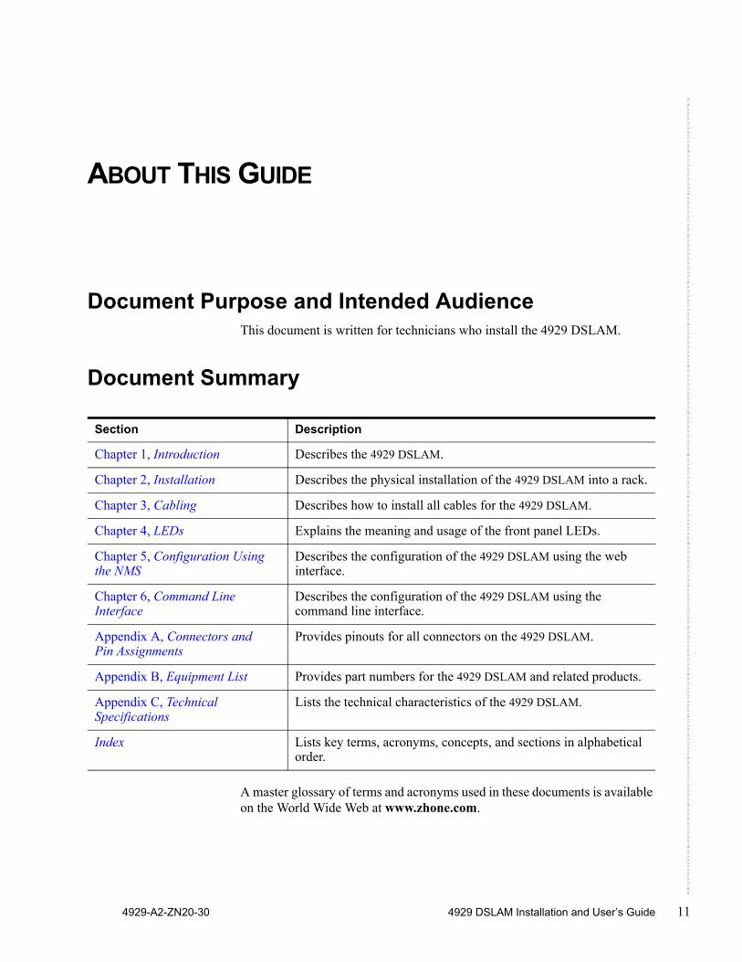
Document Purpose and Intended AudienceThis document is written for technicians who install the 4929 DSLAM.
Document Summary
A master glossary of terms and acronyms used in these documents is available on the World Wide Web at www.zhone.com.
Section Description
Chapter 1, Introduction Describes the 4929 DSLAM.
Chapter 2, Installation Describes the physical installation of the 4929 DSLAM into a rack.
Chapter 3, Cabling Describes how to install all cables for the 4929 DSLAM.
Chapter 4, LEDs Explains the meaning and usage of the front panel LEDs.
Chapter 5, Configuration Using the NMS
Describes the configuration of the 4929 DSLAM using the web interface.
Chapter 6, Command Line Interface
Describes the configuration of the 4929 DSLAM using the command line interface.
Appendix A, Connectors and Pin Assignments
Provides pinouts for all connectors on the 4929 DSLAM.
Appendix B, Equipment List Provides part numbers for the 4929 DSLAM and related products.
Appendix C, Technical Specifications
Lists the technical characteristics of the 4929 DSLAM.
Index Lists key terms, acronyms, concepts, and sections in alphabetical order.
12 4929 DSLAM Installation and User’s Guide 4929-A2-ZN20-30
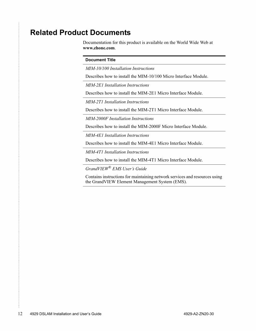
Related Product DocumentsDocumentation for this product is available on the World Wide Web at www.zhone.com.
Document Title
MIM-10/100 Installation Instructions
Describes how to install the MIM-10/100 Micro Interface Module.
MIM-2E1 Installation Instructions
Describes how to install the MIM-2E1 Micro Interface Module.
MIM-2T1 Installation Instructions
Describes how to install the MIM-2T1 Micro Interface Module.
MIM-2000F Installation Instructions
Describes how to install the MIM-2000F Micro Interface Module.
MIM-4E1 Installation Instructions
Describes how to install the MIM-4E1 Micro Interface Module.
MIM-4T1 Installation Instructions
Describes how to install the MIM-4T1 Micro Interface Module.
GrandVIEW® EMS User’s Guide
Contains instructions for maintaining network services and resources using the GrandVIEW Element Management System (EMS).
Contacting Global Service and Support
4929-A2-ZN20-30 4929 DSLAM Installation and User’s Guide 13
Contacting Global Service and SupportContact Global Service and Support (GSS) if you have any questions about this or other Zhone products. Before contacting GSS, make sure you have the following information:
Zhone product you are using
System configuration
Software version running on the system
Description of the issue
Technical SupportIf you require assistance with the installation or operation of your product, or if you want to return a product for repair under warranty, contact GSS. The contact information is as follows:
If you purchased the product from an authorized dealer, distributor, Value Added Reseller (VAR), or third party, contact that supplier for technical assistance and warranty support.
Service RequirementsIf the product malfunctions, all repairs must be performed by the manufacturer or a Zhone-authorized agent. It is the responsibility of users requiring service to report the need for service to GSS.
E-mail [email protected]
Telephone (North America) 877-ZHONE20
Telephone (International) 510-777-7133
Internet www.zhone.com/support

14 4929 DSLAM Installation and User’s Guide 4929-A2-ZN20-30
4929-A2-ZN20-30 4929 DSLAM Installation and User’s Guide 15
INTRODUCTION
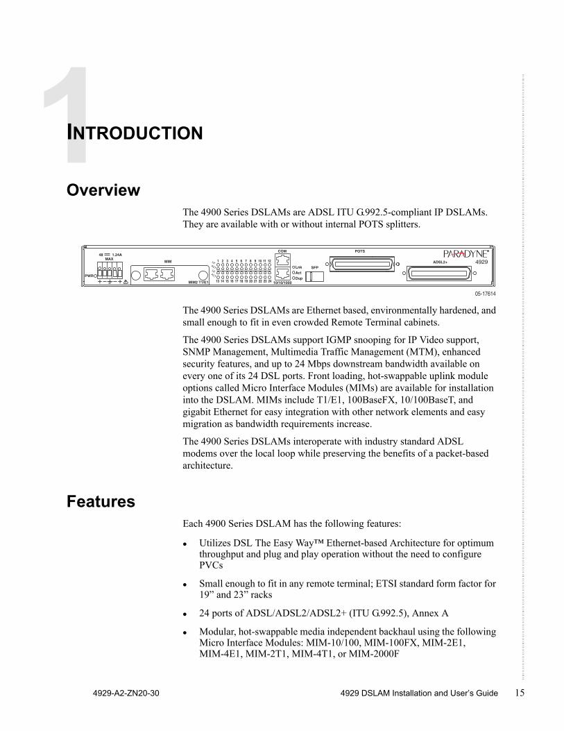
OverviewThe 4900 Series DSLAMs are ADSL ITU G.992.5-compliant IP DSLAMs. They are available with or without internal POTS splitters.
The 4900 Series DSLAMs are Ethernet based, environmentally hardened, and small enough to fit in even crowded Remote Terminal cabinets.
The 4900 Series DSLAMs support IGMP snooping for IP Video support, SNMP Management, Multimedia Traffic Management (MTM), enhanced security features, and up to 24 Mbps downstream bandwidth available on every one of its 24 DSL ports. Front loading, hot-swappable uplink module options called Micro Interface Modules (MIMs) are available for installation into the DSLAM. MIMs include T1/E1, 100BaseFX, 10/100BaseT, and gigabit Ethernet for easy integration with other network elements and easy migration as bandwidth requirements increase.
The 4900 Series DSLAMs interoperate with industry standard ADSL modems over the local loop while preserving the benefits of a packet-based architecture.
FeaturesEach 4900 Series DSLAM has the following features:
Utilizes DSL The Easy Way™ Ethernet-based Architecture for optimum throughput and plug and play operation without the need to configure PVCs
Small enough to fit in any remote terminal; ETSI standard form factor for 19” and 23” racks
24 ports of ADSL/ADSL2/ADSL2+ (ITU G.992.5), Annex A
Modular, hot-swappable media independent backhaul using the following Micro Interface Modules: MIM-10/100, MIM-100FX, MIM-2E1, MIM-4E1, MIM-2T1, MIM-4T1, or MIM-2000F
����
�����
��������
��
� �������� � � � � � � � � � � � � � � �
��������������������������������������������
����������
���
���
���
�������������
���
����������
���
�
���
����
�
�
���
�
Introduction
16 4929 DSLAM Installation and User’s Guide 4929-A2-ZN20-30
Compliant to ETSI 300-119-1-3 Environmental Requirements
MTM for enhanced security and prioritization
Embedded web-based management system for easy, platform-independent remote management, and SNMP for remote monitoring
IGMP snooping for multicast video support
Available with integral 600 Ohm POTS splitters, 900 Ohm POTS, or ISDN splitters
4929-A2-ZN20-30 4929 DSLAM Installation and User’s Guide 17
INSTALLATION
PreparationConsider the following before installing the DSLAM:
Installation Site – Your installation site should be well ventilated, clean, and free of environmental extremes.
Installation Options – The DSLAM may be: — Mounted with the included mounting brackets in a standard 19-inch
(483 mm) or 23-inch (584 mm) rack (including both Bay Networks and Nortel 23-inch racks), or, with separately purchased mounting brackets, in a 21-inch (535 mm) ETSI rack. ETSI brackets are available. See Appendix B, Equipment List.As many 4900 Series DSLAMs may be mounted in a standard rack as there are 1.75-inch (44.45 mm) spaces in the rack, so long as adequate cooling is provided.
— Mounted on a wall.— Set on a shelf or desktop.
Up to eight 4900 Series DSLAMs may be stacked on a shelf or desktop. Different models can be mixed in a stack.
Power – The DSLAM operates from a –48 VDC power supply to allow for standard power connections available in a CO. For AC voltage environments, an external AC-to-DC power converter is required.
Installation
18 4929 DSLAM Installation and User’s Guide 4929-A2-ZN20-30
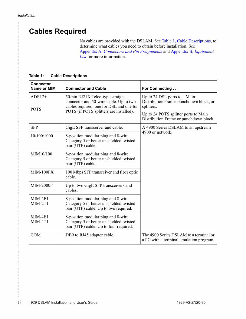
Cables RequiredNo cables are provided with the DSLAM. See Table 1, Cable Descriptions, to determine what cables you need to obtain before installation. See Appendix A, Connectors and Pin Assignments and Appendix B, Equipment List for more information.
Table 1: Cable Descriptions
Connector Name or MIM Connector and Cable For Connecting . . .
ADSL2+
POTS
50-pin RJ21X Telco-type straight connector and 50-wire cable. Up to two cables required: one for DSL and one for POTS (if POTS splitters are installed).
Up to 24 DSL ports to a Main Distribution Frame, punchdown block, or splitters.
Up to 24 POTS splitter ports to Main Distribution Frame or punchdown block.
SFP GigE SFP transceiver and cable. A 4900 Series DSLAM to an upstream 4900 or network.
10/100/1000 8-position modular plug and 8-wire Category 5 or better unshielded twisted pair (UTP) cable.
MIM10/100 8-position modular plug and 8-wire Category 5 or better unshielded twisted pair (UTP) cable.
MIM-100FX 100 Mbps SFP transceiver and fiber optic cable.
MIM-2000F Up to two GigE SFP transceivers and cables.
MIM-2E1MIM-2T1
8-position modular plug and 8-wire Category 5 or better unshielded twisted pair (UTP) cable. Up to two required.
MIM-4E1MIM-4T1
8-position modular plug and 8-wire Category 5 or better unshielded twisted pair (UTP) cable. Up to four required.
COM DB9 to RJ45 adapter cable. The 4900 Series DSLAM to a terminal or a PC with a terminal emulation program.
Unpacking the Hardware
4929-A2-ZN20-30 4929 DSLAM Installation and User’s Guide 19
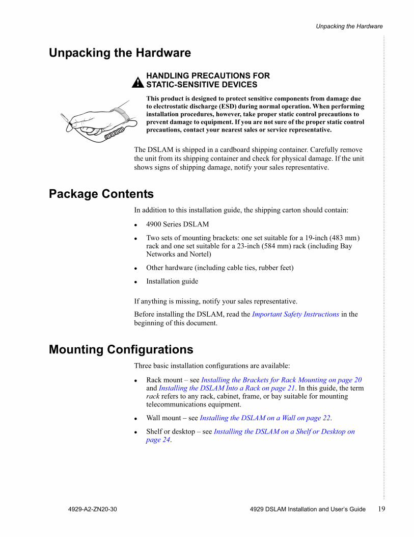
Unpacking the Hardware
HANDLING PRECAUTIONS FOR STATIC-SENSITIVE DEVICES This product is designed to protect sensitive components from damage due to electrostatic discharge (ESD) during normal operation. When performing installation procedures, however, take proper static control precautions to prevent damage to equipment. If you are not sure of the proper static control precautions, contact your nearest sales or service representative.
The DSLAM is shipped in a cardboard shipping container. Carefully remove the unit from its shipping container and check for physical damage. If the unit shows signs of shipping damage, notify your sales representative.
Package Contents In addition to this installation guide, the shipping carton should contain:
4900 Series DSLAM
Two sets of mounting brackets: one set suitable for a 19-inch (483 mm) rack and one set suitable for a 23-inch (584 mm) rack (including Bay Networks and Nortel)
Other hardware (including cable ties, rubber feet)
Installation guide
If anything is missing, notify your sales representative.
Before installing the DSLAM, read the Important Safety Instructions in the beginning of this document.
Mounting Configurations Three basic installation configurations are available:
Rack mount – see Installing the Brackets for Rack Mounting on page 20 and Installing the DSLAM Into a Rack on page 21. In this guide, the term rack refers to any rack, cabinet, frame, or bay suitable for mounting telecommunications equipment.
Wall mount – see Installing the DSLAM on a Wall on page 22.
Shelf or desktop – see Installing the DSLAM on a Shelf or Desktop on page 24.
!
Installation
20 4929 DSLAM Installation and User’s Guide 4929-A2-ZN20-30
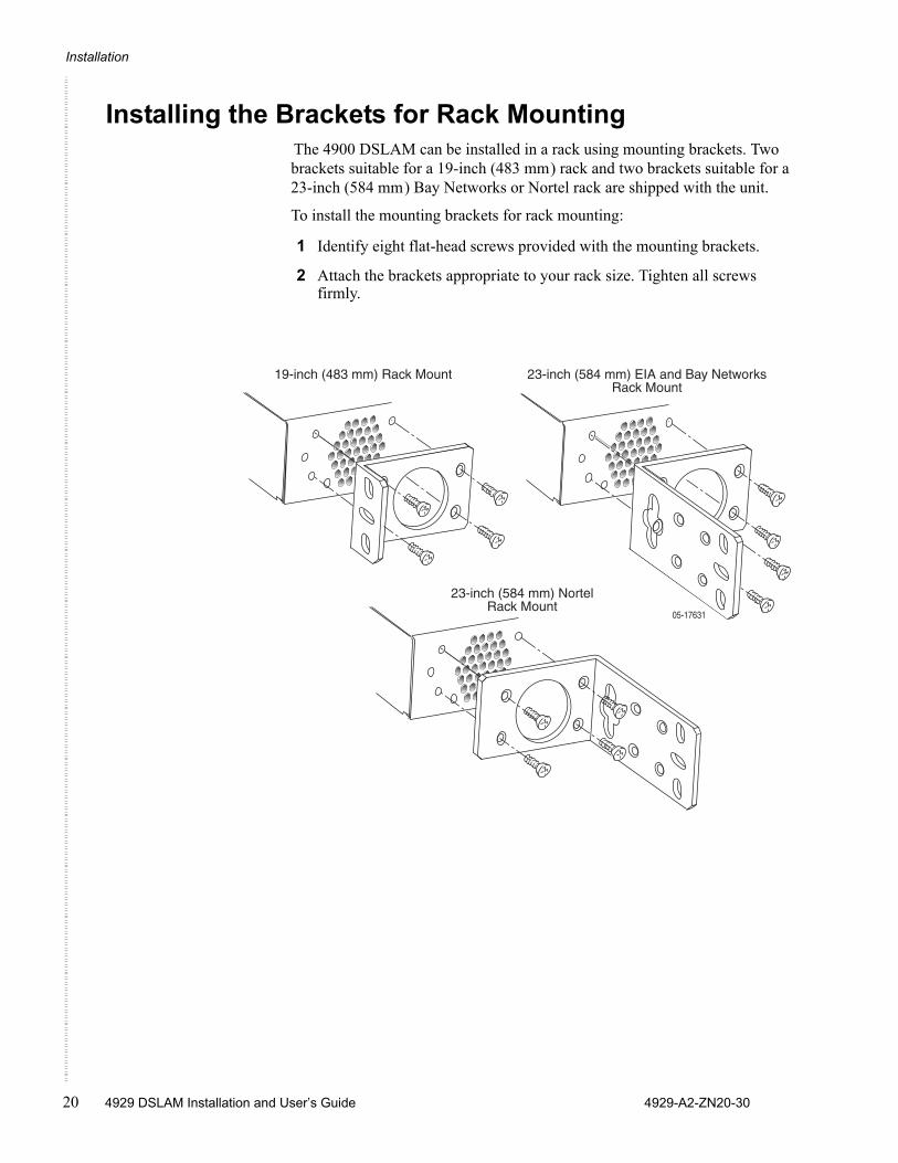
Installing the Brackets for Rack Mounting The 4900 DSLAM can be installed in a rack using mounting brackets. Two brackets suitable for a 19-inch (483 mm) rack and two brackets suitable for a 23-inch (584 mm) Bay Networks or Nortel rack are shipped with the unit.
To install the mounting brackets for rack mounting:
1 Identify eight flat-head screws provided with the mounting brackets.
2 Attach the brackets appropriate to your rack size. Tighten all screws firmly.
��������
��� ����������������� ���������� !"#$��"�% & �
'��� �����������$��"�% & �
��� ������������� !��($��"�% & �
Installing the DSLAM Into a Rack
4929-A2-ZN20-30 4929 DSLAM Installation and User’s Guide 21
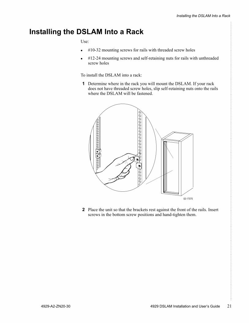
Installing the DSLAM Into a RackUse:
#10-32 mounting screws for rails with threaded screw holes
#12-24 mounting screws and self-retaining nuts for rails with unthreaded screw holes
To install the DSLAM into a rack:
1 Determine where in the rack you will mount the DSLAM. If your rack does not have threaded screw holes, slip self-retaining nuts onto the rails where the DSLAM will be fastened.
2 Place the unit so that the brackets rest against the front of the rails. Insert screws in the bottom screw positions and hand-tighten them.
02-17070
Installation
22 4929 DSLAM Installation and User’s Guide 4929-A2-ZN20-30
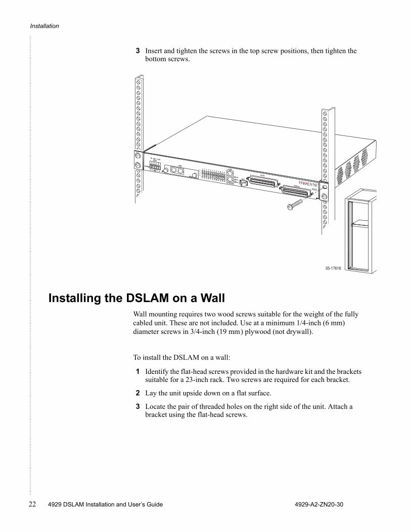
3 Insert and tighten the screws in the top screw positions, then tighten the bottom screws.
Installing the DSLAM on a WallWall mounting requires two wood screws suitable for the weight of the fully cabled unit. These are not included. Use at a minimum 1/4-inch (6 mm) diameter screws in 3/4-inch (19 mm) plywood (not drywall).
To install the DSLAM on a wall:
1 Identify the flat-head screws provided in the hardware kit and the brackets suitable for a 23-inch rack. Two screws are required for each bracket.
2 Lay the unit upside down on a flat surface.
3 Locate the pair of threaded holes on the right side of the unit. Attach a bracket using the flat-head screws.
��������
����
�����
��
� ��������
� � � � � � � � � � � � � � �
��������������������������������������������
����������
���
�������������������
���
����������
���
����
����
��
���
�
Installing the DSLAM on a Wall
4929-A2-ZN20-30 4929 DSLAM Installation and User’s Guide 23
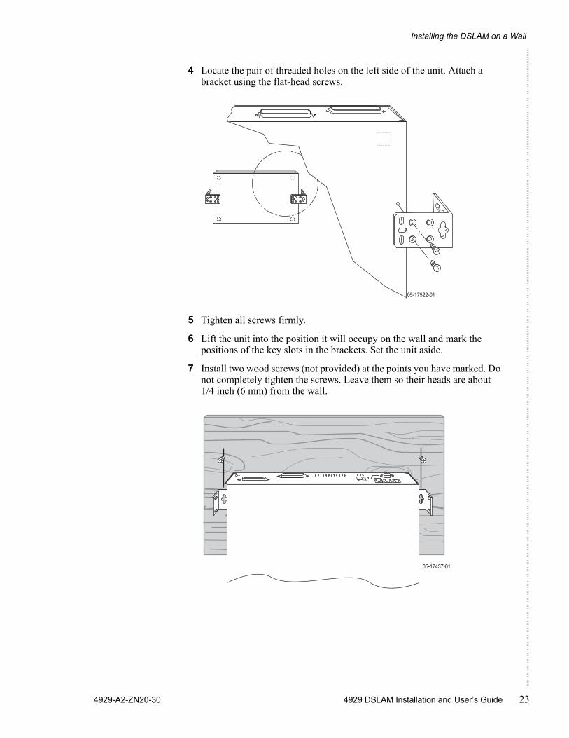
4 Locate the pair of threaded holes on the left side of the unit. Attach a bracket using the flat-head screws.
5 Tighten all screws firmly.
6 Lift the unit into the position it will occupy on the wall and mark the positions of the key slots in the brackets. Set the unit aside.
7 Install two wood screws (not provided) at the points you have marked. Do not completely tighten the screws. Leave them so their heads are about 1/4 inch (6 mm) from the wall.
���������
�����������
Installation
24 4929 DSLAM Installation and User’s Guide 4929-A2-ZN20-30
8 Hang the unit from the wood screws to verify that the screws are properly placed. The screws should freely slide into the top of the key slots in the brackets.Do not fasten the unit to the wall until after it is completely cabled and tested.
Installing the DSLAM on a Shelf or DesktopIf the DSLAM will be placed on a shelf or desktop, install the provided rubber feet before putting the unit in position.
To install the DSLAM on a shelf or desktop, as a standalone unit or in a stack:
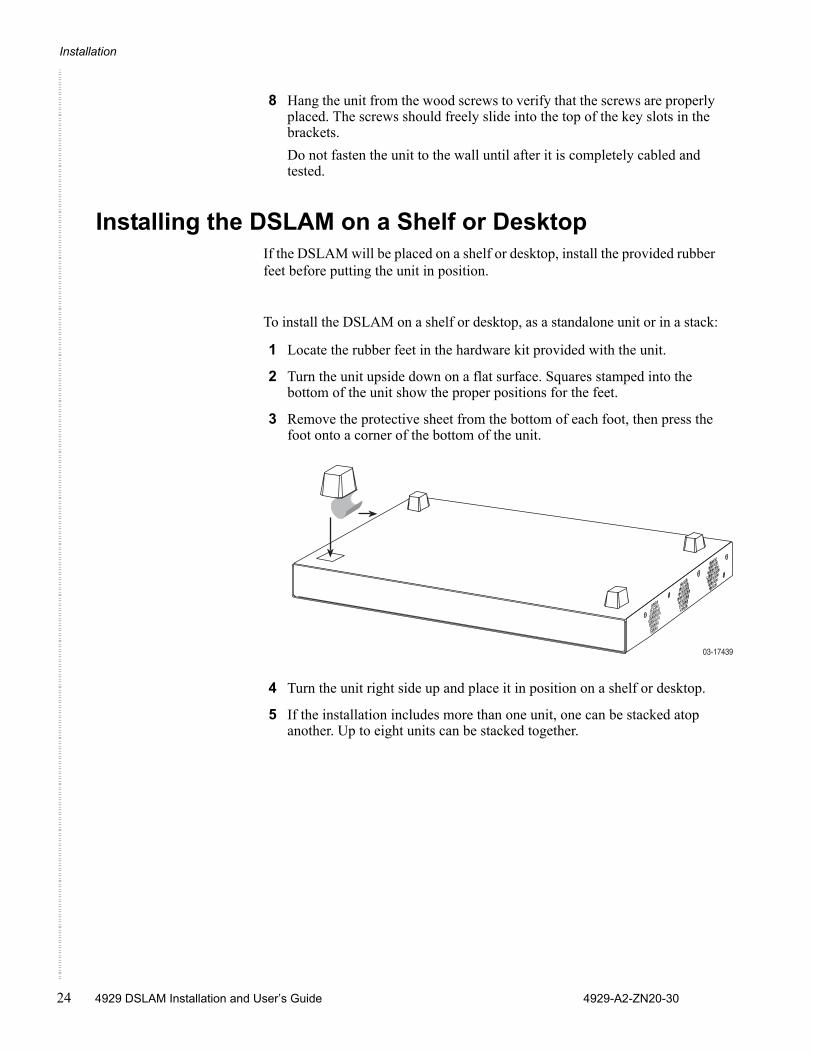
1 Locate the rubber feet in the hardware kit provided with the unit.
2 Turn the unit upside down on a flat surface. Squares stamped into the bottom of the unit show the proper positions for the feet.
3 Remove the protective sheet from the bottom of each foot, then press the foot onto a corner of the bottom of the unit.
4 Turn the unit right side up and place it in position on a shelf or desktop.
5 If the installation includes more than one unit, one can be stacked atop another. Up to eight units can be stacked together.
03-17439
4929-A2-ZN20-30 4929 DSLAM Installation and User’s Guide 25
CABLING
Cabling OverviewThe 4900 Series DSLAM has a large variety of possible cabling configurations. This chapter describes all possible connections, not all of which are required:
Installing the Micro Interface Module on page 26
Connecting the ADSL2+ and POTS Connectors on page 27
Connecting the SFP Connector or the 10/100/1000 Connector on page 28
Connecting the COM Port on page 30
Connecting to Power on page 31
Cabling
26 4929 DSLAM Installation and User’s Guide 4929-A2-ZN20-30
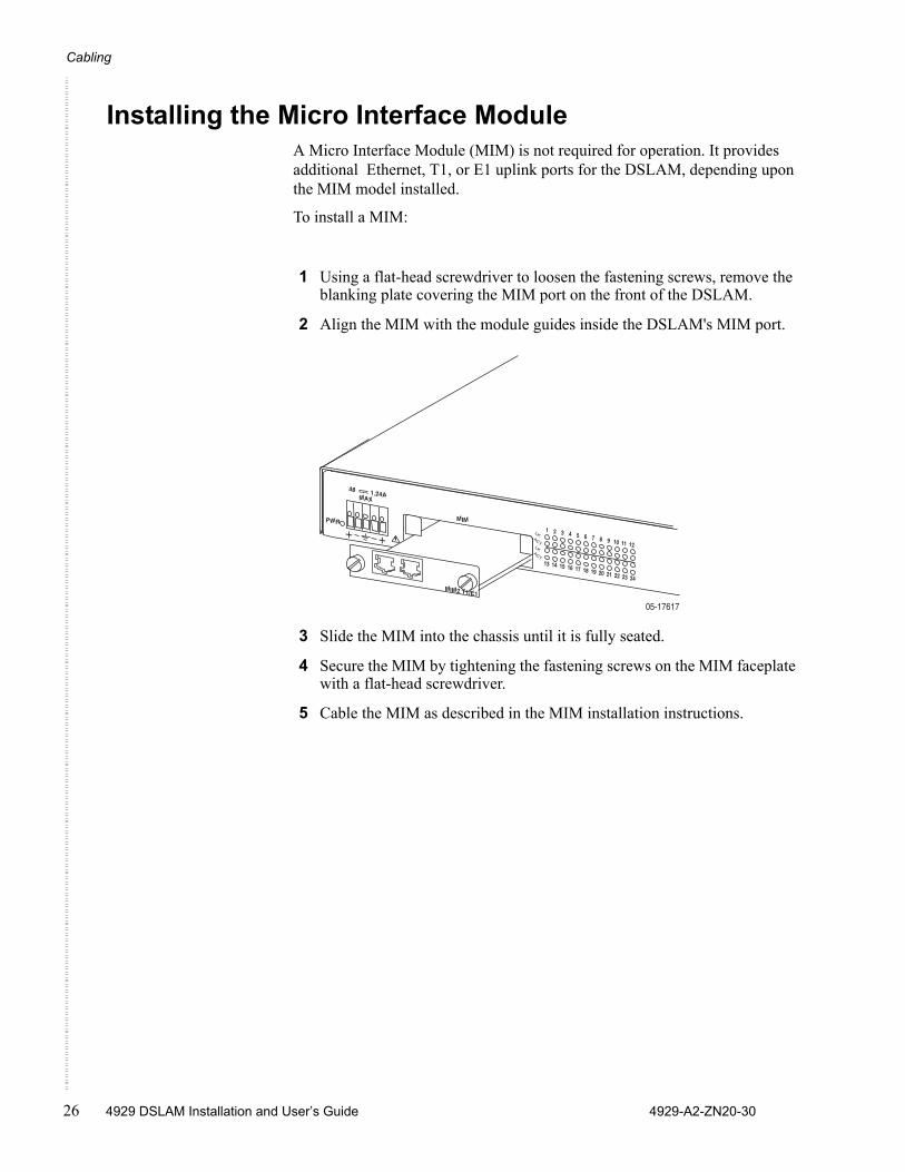
Installing the Micro Interface ModuleA Micro Interface Module (MIM) is not required for operation. It provides additional Ethernet, T1, or E1 uplink ports for the DSLAM, depending upon the MIM model installed.
To install a MIM:
1 Using a flat-head screwdriver to loosen the fastening screws, remove the blanking plate covering the MIM port on the front of the DSLAM.
2 Align the MIM with the module guides inside the DSLAM's MIM port.
3 Slide the MIM into the chassis until it is fully seated.
4 Secure the MIM by tightening the fastening screws on the MIM faceplate with a flat-head screwdriver.
5 Cable the MIM as described in the MIM installation instructions.
��������
��
� ��������
� � � � � � � � � � � � � � �
��������������������������������������������
����������
����������
���
������
���
�
Connecting the ADSL2+ and POTS Connectors
4929-A2-ZN20-30 4929 DSLAM Installation and User’s Guide 27
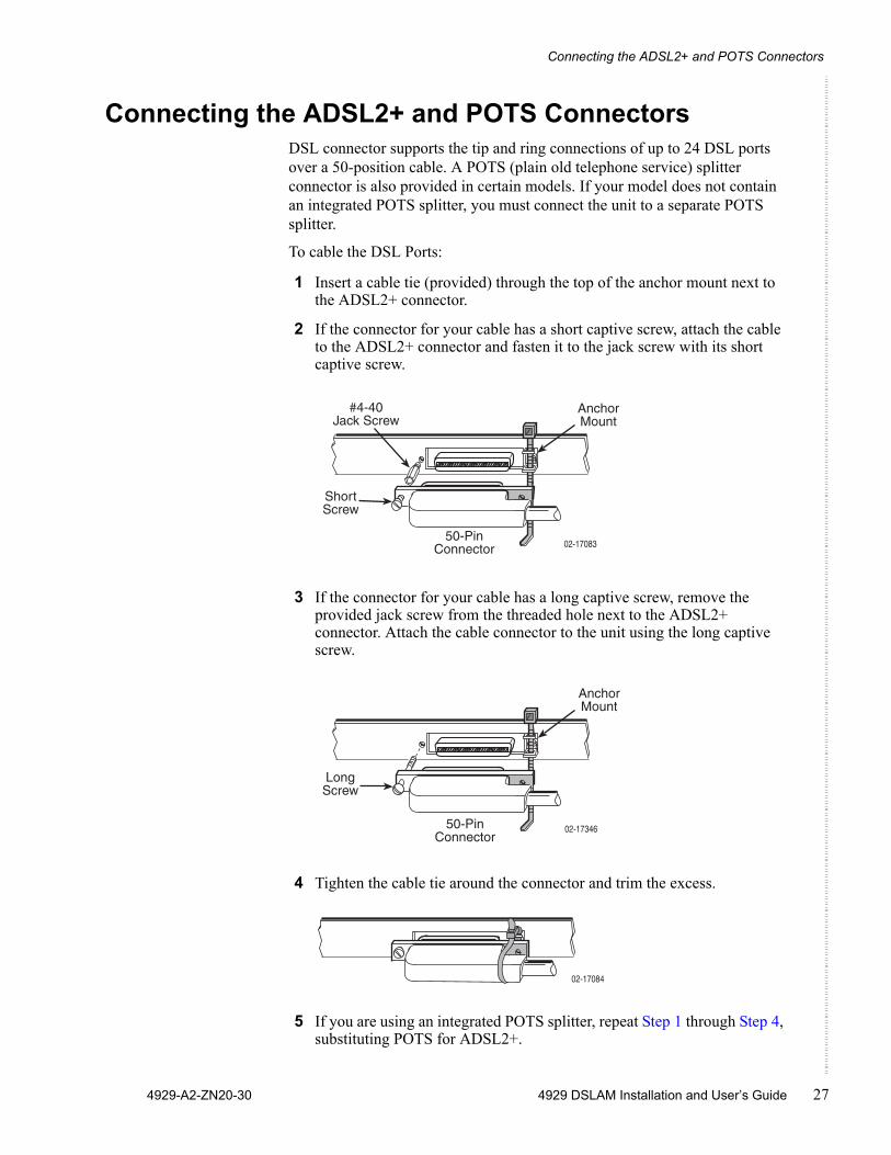
Connecting the ADSL2+ and POTS ConnectorsDSL connector supports the tip and ring connections of up to 24 DSL ports over a 50-position cable. A POTS (plain old telephone service) splitter connector is also provided in certain models. If your model does not contain an integrated POTS splitter, you must connect the unit to a separate POTS splitter.
To cable the DSL Ports:
1 Insert a cable tie (provided) through the top of the anchor mount next to the ADSL2+ connector.
2 If the connector for your cable has a short captive screw, attach the cable to the ADSL2+ connector and fasten it to the jack screw with its short captive screw.
3 If the connector for your cable has a long captive screw, remove the provided jack screw from the threaded hole next to the ADSL2+ connector. Attach the cable connector to the unit using the long captive screw.
4 Tighten the cable tie around the connector and trim the excess.
5 If you are using an integrated POTS splitter, repeat Step 1 through Step 4, substituting POTS for ADSL2+.
ShortScrew
#4-40Jack Screw
02-17083
AnchorMount
50-PinConnector
�������
� �� !% & �
�)�*� � ��� !
� +,�!��
02-17084

Cabling
28 4929 DSLAM Installation and User’s Guide 4929-A2-ZN20-30
6 Install the supplied large ferrite chokes on the DSL and POTS cables as close as possible to the connectors. If necessary, use cables ties to hold the chokes in place.
7 Secure the cables as required for strain relief.
Connecting the SFP Connector or the 10/100/1000 Connector
There are two Ethernet interfaces on the faceplate of the DSLAM, only one of which may be used at a time:
An 8-position modular jack providing support for 1000BaseT
A Small Form-Factor Pluggable (SFP) socket providing, with the appropriate transceiver installed, support for 1000BaseX and 1000BaseT. See Appendix B, Equipment List.
Either interface can be used as the uplink for a single DSLAM, or for the terminating unit in a stack of DSLAMs.
To use the SFP connector or 10/100/1000 connector:
1 Connect the uplink cable to the DSLAM:— For a wire connection, plug the 8-position modular plug of your
uplink cable into the 10/100/1000 modular jack. A straight-through cable can be used regardless of the destination interface, since the port automatically distinguishes between a Medium-Dependent Interface (MDI) and an MDI Crossover (MDIX).Install the supplied small ferrite choke on the cable as close as possible to the jack. Use a cable tie to hold the choke in place.
��������
����
�����
���
�������������������
���
����
-�!!����� "�#
Connecting DSLAMs to Each Other
4929-A2-ZN20-30 4929 DSLAM Installation and User’s Guide 29
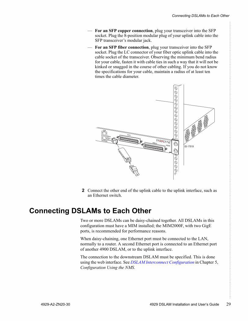
— For an SFP copper connection, plug your transceiver into the SFP socket. Plug the 8-position modular plug of your uplink cable into the SFP transceiver’s modular jack.
— For an SFP fiber connection, plug your transceiver into the SFP socket. Plug the LC connector of your fiber optic uplink cable into the cable socket of the transceiver. Observing the minimum bend radius for your cable, fasten it with cable ties in such a way that it will not be kinked or snagged in the course of other cabling. If you do not know the specifications for your cable, maintain a radius of at least ten times the cable diameter.
2 Connect the other end of the uplink cable to the uplink interface, such as an Ethernet switch.
Connecting DSLAMs to Each OtherTwo or more DSLAMs can be daisy-chained together. All DSLAMs in this configuration must have a MIM installed; the MIM2000F, with two GigE ports, is recommended for performance reasons.
When daisy-chaining, one Ethernet port must be connected to the LAN, normally to a router. A second Ethernet port is connected to an Ethernet port of another 4900 DSLAM, or to the uplink interface.
The connection to the downstream DSLAM must be specified. This is done using the web interface. See DSLAM Interconnect Configuration in Chapter 5, Configuration Using the NMS.
�������
����
�����
���
�������������������
���
����
Cabling
30 4929 DSLAM Installation and User’s Guide 4929-A2-ZN20-30
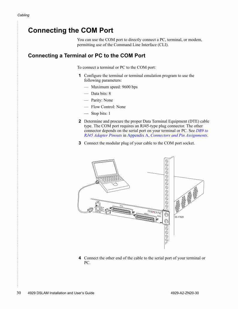
Connecting the COM PortYou can use the COM port to directly connect a PC, terminal, or modem, permitting use of the Command Line Interface (CLI).
Connecting a Terminal or PC to the COM Port
To connect a terminal or PC to the COM port:
1 Configure the terminal or terminal emulation program to use the following parameters:— Maximum speed: 9600 bps— Data bits: 8— Parity: None— Flow Control: None— Stop bits: 1
2 Determine and procure the proper Data Terminal Equipment (DTE) cable type. The COM port requires an RJ45-type plug connector. The other connector depends on the serial port on your terminal or PC. See DB9 to RJ45 Adapter Pinouts in Appendix A, Connectors and Pin Assignments.
3 Connect the modular plug of your cable to the COM port socket.
4 Connect the other end of the cable to the serial port of your terminal or PC.
�������
����
�����
���
�������������������
���
����

Connecting to Power
4929-A2-ZN20-30 4929 DSLAM Installation and User’s Guide 31
Connecting a Modem to the COM Port
To connect a modem to the COM port:
1 Determine and procure the proper DCE cable type for your modem. The COM port requires an RJ45-type plug connector. The other connector depends on the serial port on your modem. The connection requires an EIA-232E crossover (null modem) cable or adapter. See DB9 to RJ45 Adapter Pinouts in Appendix A, Connectors and Pin Assignments.
2 Connect the modular plug connector of your cable to the COM port socket.
3 Connect the other end of the cable or adapter to the serial port of your modem.
Connecting to PowerThe 4900 Series DSLAM is powered by a nominal –48 VDC source. Dual power feeds are provided for redundancy. The terminal block accepts 18 to 14 AWG wire.
The DC power terminal block on the DSLAM has five terminals: two positive, two negative, and one ground. Only one positive terminal and one negative terminal pair need be connected for operational purposes. The second positive and negative terminal pair may be connected to a backup DC power supply for redundancy. The ground terminal must be connected regardlessly. DO NOT OPERATE THE DSLAM WITHOUT A GROUND CONNECTION.
To connect the DSLAM to power:
1 Make sure that the DC power source wires are not powered (that is, the circuit breakers or fuses are open at the source).
2 Strip about 1/2 inch (13 mm) of insulation off the ends of the 18–14 AWG or 0.75–2.5 mm2 solid or stranded wires you will use for power.
3 Loosen the screw above the center terminal on the DC terminal strip on the face of your DSLAM.
4 Insert your ground wire into the center terminal and tighten the screw.
5 Attach the other end of the ground wire to an earth ground.
6 Loosen the screws above the positive and negative terminals on one side of the terminal strip.
7 Insert your negative DC power lead into the negative (–) terminal and then tighten the screw.
8 Insert your positive DC power lead into the positive (+) terminal and then tighten the screw.
9 Repeat Step 6 through Step 8 if you have a redundant power source.
Cabling
32 4929 DSLAM Installation and User’s Guide 4929-A2-ZN20-30
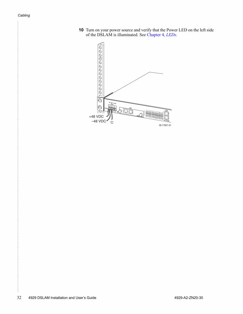
10 Turn on your power source and verify that the Power LED on the left side of the DSLAM is illuminated. See Chapter 4, LEDs.
����������
��
� ��������
� � � � � � � � � � � � � � �
��������������������������������������������
����������
���
����������
����������
���
������
���
�
����./�0���./�
4929-A2-ZN20-30 4929 DSLAM Installation and User’s Guide 33
LEDS
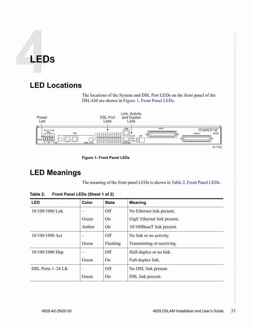
LED LocationsThe locations of the System and DSL Port LEDs on the front panel of the DSLAM are shown in Figure 1, Front Panel LEDs.
Figure 1: Front Panel LEDs
LED MeaningsThe meaning of the front panel LEDs is shown in Table 2, Front Panel LEDs.
����
�����
������
��
� �������� � � � � � � � � � � � � � � �
��������������������������������������������
����������
���
���
���
�������������
���
����������
���
* ��!���
/,��* !����#
�� "1�����2���� ��/&3(�4
���#
�
���
����
�
�
���
�
Table 2: Front Panel LEDs (Sheet 1 of 2)
LED Color State Meaning
10/100/1000 Lnk –
Green
Amber
Off
On
On
No Ethernet link present.
GigE Ethernet link present.
10/100BaseT link present.
10/100/1000 Act –
Green
Off
Flashing
No link or no activity.
Transmitting or receiving.
10/100/1000 Dup –
Green
Off
On
Half-duplex or no link.
Full-duplex link.
DSL Ports 1–24 LK –
Green
Off
On
No DSL link present.
DSL link present.
LEDs
34 4929 DSLAM Installation and User’s Guide 4929-A2-ZN20-30
DSL Ports 1–24 ACT –
Amber
Green
Off
Flashing
Flashing
No activity or no link.
Receiving data.
Transmitting data.
PWR Green Off
On
No power is applied to the DSLAM.
Power is applied to the DSLAM.
Table 2: Front Panel LEDs (Sheet 2 of 2)
LED Color State Meaning
4929-A2-ZN20-30 4929 DSLAM Installation and User’s Guide 35
CONFIGURATION USING THE NMS
OverviewThe 4900 Series DSLAMs have an integral web interface that you can access with a web browser. The DSLAM’s integral Network Management System (NMS) lets you configure and monitor the DSLAM using a standard web browser.
Web Interface System RequirementsWeb Browser – Required for running NMS. Compatible web browsers include, but are not limited to, Microsoft Internet Explorer (version 6.0 or higher) and Netscape Navigator (version 6.0 or higher). NMS is optimized for use with Internet Explorer.
Use your browser's default settings when running NMS. JavaScript must be enabled.
Screen Resolution – 1024 x 768 pixels is the minimum resolution required for all NMS views to fit within the dimensions of most monitors and laptops. Lower screen resolutions (such as 800 x 600 pixels) may cause NMS screens to exceed the width or height of the screen. To verify screen resolution on a Windows system:— Right click on your desktop— Select Properties— Click the Settings tab— Adjust the Screen Resolution as needed
Configuration Using the NMS
36 4929 DSLAM Installation and User’s Guide 4929-A2-ZN20-30
Configuring Your Windows PC to Communicate with NMS
To communicate with NMS, your PC’s Ethernet interface must be on the same subnet as the network extender. For example, to configure the IP address under Windows XP:
1 In the Windows task bar, click on the Start button, and then click on Control Panel.
2 Double-click on the Network Connections icon.
3 In the LAN or High-Speed Internet window, right-click on the icon corresponding to your network interface card (NIC) and select Properties. (Often this icon is labeled Local Area Connection.) The Local Area Connection dialog box is displayed with a list of currently installed network items.
4 Ensure that the check box to the left of the item labeled Internet Protocol (TCP/IP) is checked, and click on Properties.
5 Write down the current IP Address and Subnet Mask in the Internet Protocol (TCP/IP) Properties dialog box. When you are done using NMS, you will need to reconfigure your PC with these values.
6 In the Internet Protocol (TCP/IP) Properties dialog box, click in the radio button labeled “Use the following IP address” and type 192.168.254.x (where x is any number between 3 and 250, inclusive) in the IP Address field.
7 Type 255.255.255.0 in the Subnet Mask field.
8 Click on OK twice to confirm your changes, and close the Control Panel.
9 Start your web browser. Type 192.168.254.252 into the Address field and press Enter. The web server opening screen appears.
10 Click on >> Next >>. The login dialog box appears. Log in using:
Username: superuserPassword: Password
Configuring Your Windows PC to Communicate with NMS
4929-A2-ZN20-30 4929 DSLAM Installation and User’s Guide 37
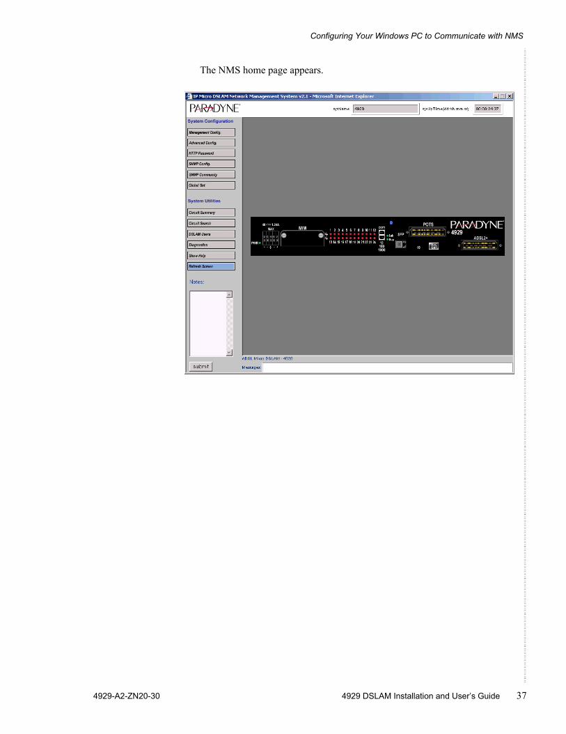
The NMS home page appears.
Configuration Using the NMS
38 4929 DSLAM Installation and User’s Guide 4929-A2-ZN20-30
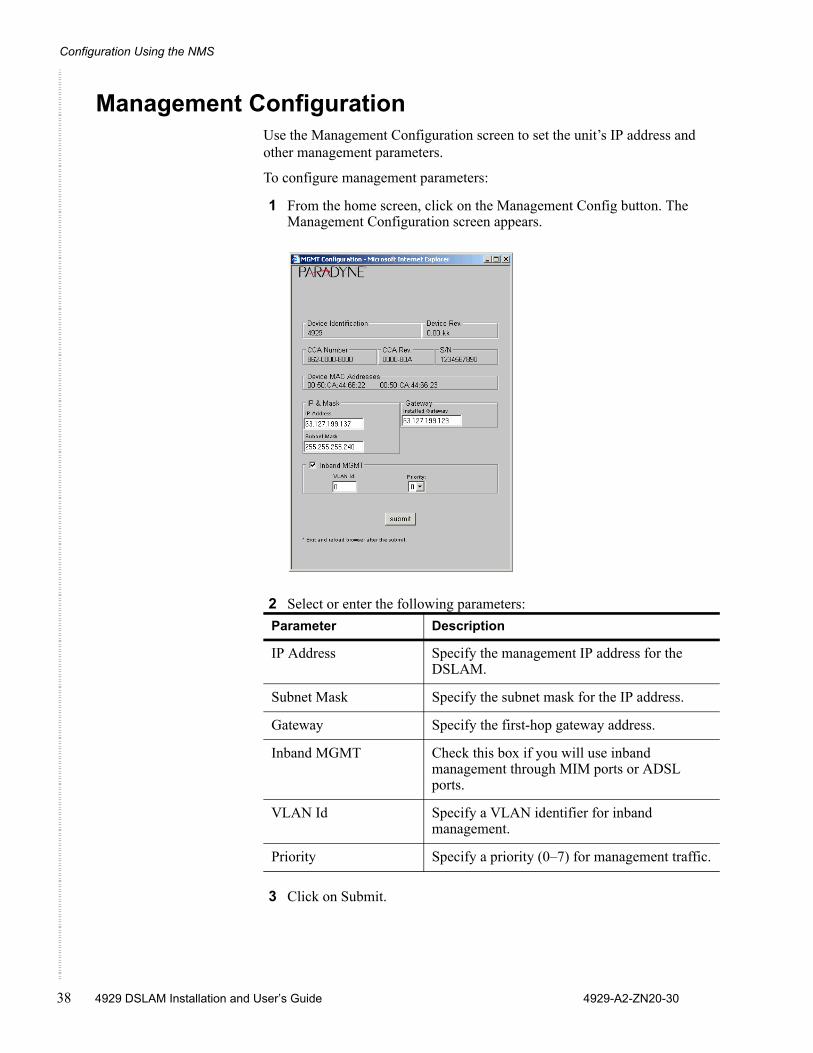
Management ConfigurationUse the Management Configuration screen to set the unit’s IP address and other management parameters.
To configure management parameters:
1 From the home screen, click on the Management Config button. The Management Configuration screen appears.
2 Select or enter the following parameters:
3 Click on Submit.
Parameter Description
IP Address Specify the management IP address for the DSLAM.
Subnet Mask Specify the subnet mask for the IP address.
Gateway Specify the first-hop gateway address.
Inband MGMT Check this box if you will use inband management through MIM ports or ADSL ports.
VLAN Id Specify a VLAN identifier for inband management.
Priority Specify a priority (0–7) for management traffic.
Advanced Configuration
4929-A2-ZN20-30 4929 DSLAM Installation and User’s Guide 39
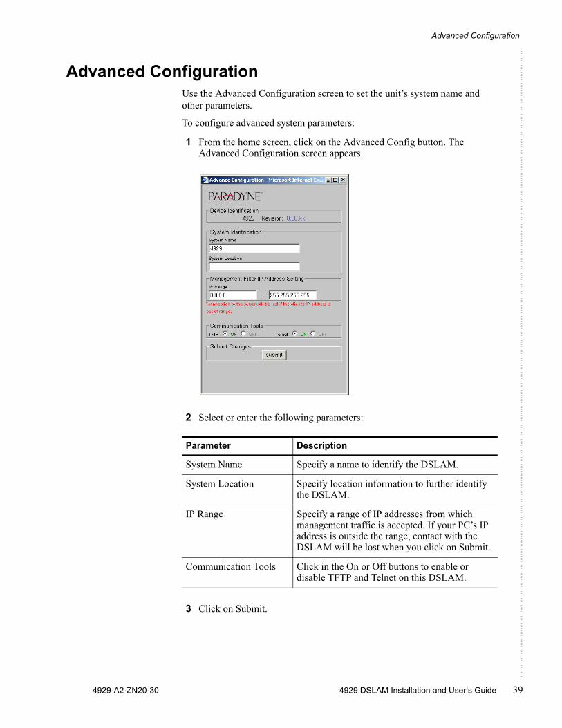
Advanced ConfigurationUse the Advanced Configuration screen to set the unit’s system name and other parameters.
To configure advanced system parameters:
1 From the home screen, click on the Advanced Config button. The Advanced Configuration screen appears.
2 Select or enter the following parameters:
3 Click on Submit.
Parameter Description
System Name Specify a name to identify the DSLAM.
System Location Specify location information to further identify the DSLAM.
IP Range Specify a range of IP addresses from which management traffic is accepted. If your PC’s IP address is outside the range, contact with the DSLAM will be lost when you click on Submit.
Communication Tools Click in the On or Off buttons to enable or disable TFTP and Telnet on this DSLAM.
Configuration Using the NMS
40 4929 DSLAM Installation and User’s Guide 4929-A2-ZN20-30
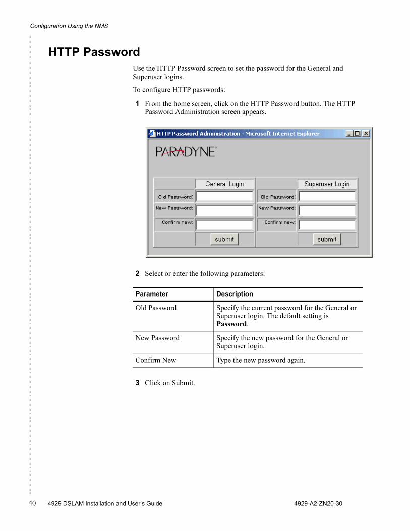
HTTP PasswordUse the HTTP Password screen to set the password for the General and Superuser logins.
To configure HTTP passwords:
1 From the home screen, click on the HTTP Password button. The HTTP Password Administration screen appears.
2 Select or enter the following parameters:
3 Click on Submit.
Parameter Description
Old Password Specify the current password for the General or Superuser login. The default setting is Password.
New Password Specify the new password for the General or Superuser login.
Confirm New Type the new password again.
SNMP Configuration
4929-A2-ZN20-30 4929 DSLAM Installation and User’s Guide 41
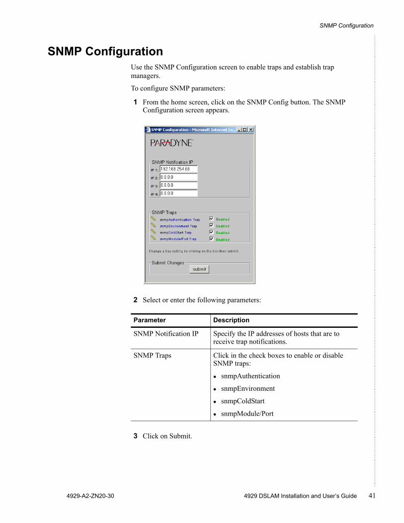
SNMP ConfigurationUse the SNMP Configuration screen to enable traps and establish trap managers.
To configure SNMP parameters:
1 From the home screen, click on the SNMP Config button. The SNMP Configuration screen appears.
2 Select or enter the following parameters:
3 Click on Submit.
Parameter Description
SNMP Notification IP Specify the IP addresses of hosts that are to receive trap notifications.
SNMP Traps Click in the check boxes to enable or disable SNMP traps:
snmpAuthentication
snmpEnvironment
snmpColdStart
snmpModule/Port
Configuration Using the NMS
42 4929 DSLAM Installation and User’s Guide 4929-A2-ZN20-30
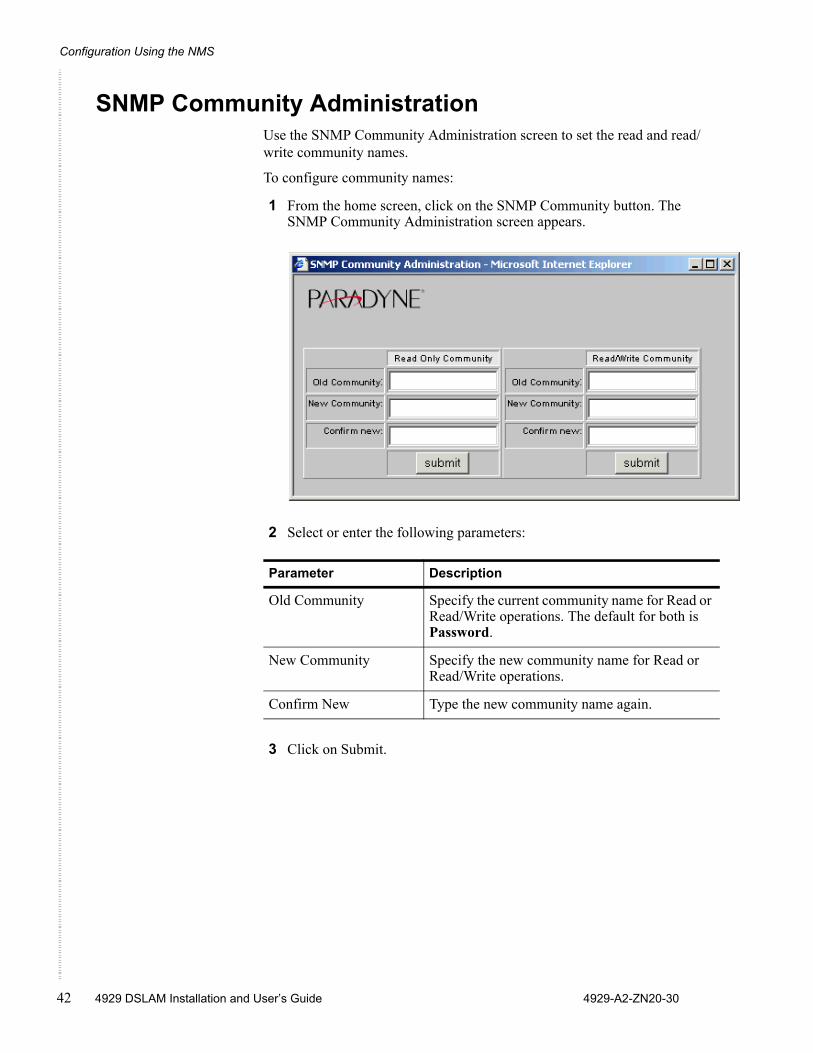
SNMP Community AdministrationUse the SNMP Community Administration screen to set the read and read/write community names.
To configure community names:
1 From the home screen, click on the SNMP Community button. The SNMP Community Administration screen appears.
2 Select or enter the following parameters:
3 Click on Submit.
Parameter Description
Old Community Specify the current community name for Read or Read/Write operations. The default for both is Password.
New Community Specify the new community name for Read or Read/Write operations.
Confirm New Type the new community name again.
Global Set
4929-A2-ZN20-30 4929 DSLAM Installation and User’s Guide 43
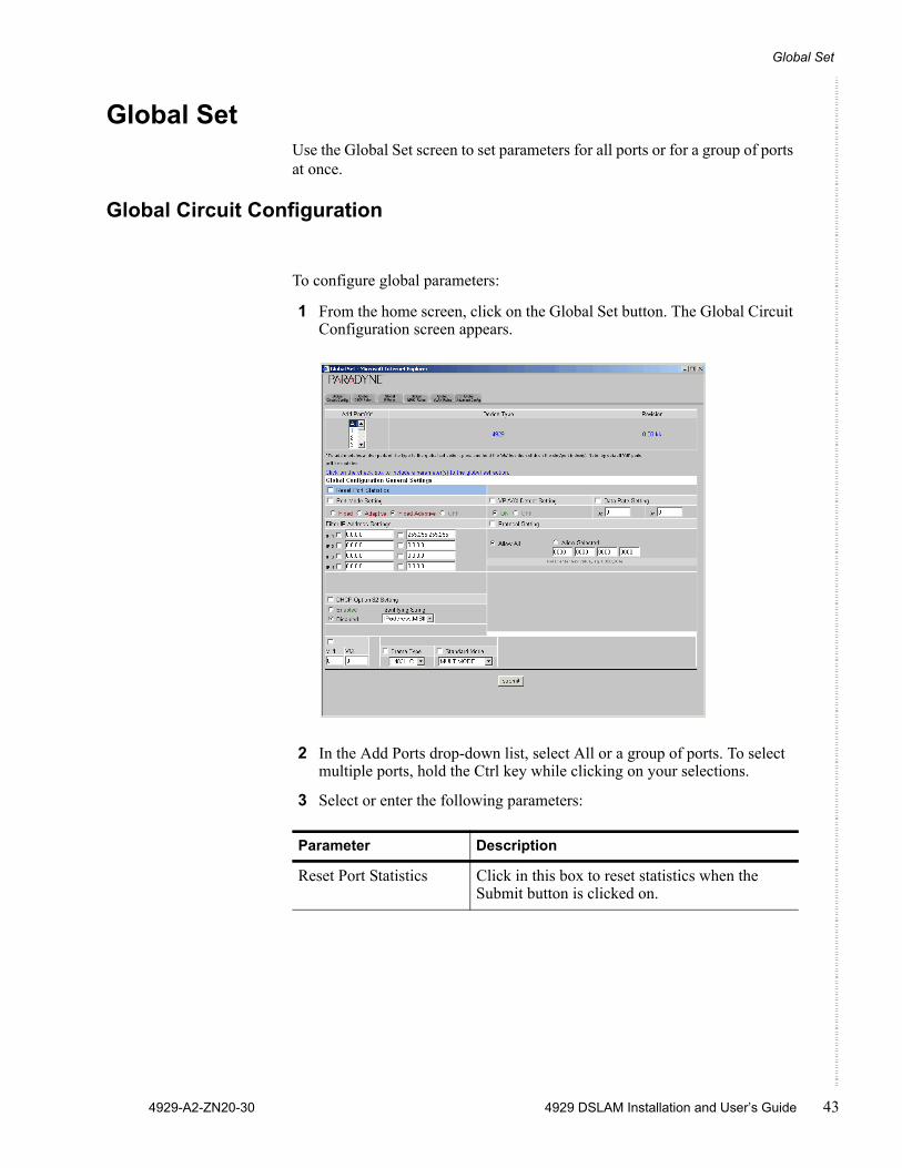
Global SetUse the Global Set screen to set parameters for all ports or for a group of ports at once.
Global Circuit Configuration
To configure global parameters:
1 From the home screen, click on the Global Set button. The Global Circuit Configuration screen appears.
2 In the Add Ports drop-down list, select All or a group of ports. To select multiple ports, hold the Ctrl key while clicking on your selections.
3 Select or enter the following parameters:
Parameter Description
Reset Port Statistics Click in this box to reset statistics when the Submit button is clicked on.
Configuration Using the NMS
44 4929 DSLAM Installation and User’s Guide 4929-A2-ZN20-30
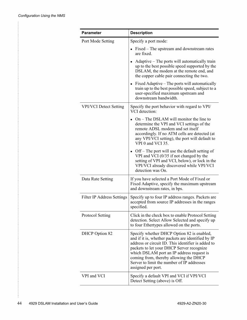
Port Mode Setting Specify a port mode:
Fixed – The upstream and downstream rates are fixed.
Adaptive – The ports will automatically train up to the best possible speed supported by the DSLAM, the modem at the remote end, and the copper cable pair connecting the two.
Fixed Adaptive – The ports will automatically train up to the best possible speed, subject to a user-specified maximum upstream and downstream bandwidth.
VPI/VCI Detect Setting Specify the port behavior with regard to VPI/VCI detection:
On – The DSLAM will monitor the line to determine the VPI and VCI settings of the remote ADSL modem and set itself accordingly. If no ATM cells are detected (at any VPI/VCI setting), the port will default to VPI 0 and VCI 35.
Off – The port will use the default setting of VPI and VCI (0/35 if not changed by the setting of VPI and VCI, below), or lock in the VPI/VCI already discovered while VPI/VCI detection was On.
Data Rate Setting If you have selected a Port Mode of Fixed or Fixed Adaptive, specify the maximum upstream and downstream rates, in bps.
Filter IP Address Settings Specify up to four IP address ranges. Packets are accepted from source IP addresses in the ranges specified.
Protocol Setting Click in the check box to enable Protocol Setting detection. Select Allow Selected and specify up to four Ethertypes allowed on the ports.
DHCP Option 82 Specify whether DHCP Option 82 is enabled, and if it is, whether packets are identified by IP address or circuit ID. This identifier is added to packets to let your DHCP Server recognize which DSLAM port an IP address request is coming from, thereby allowing the DHCP Server to limit the number of IP addresses assigned per port.
VPI and VCI Specify a default VPI and VCI if VPI/VCI Detect Setting (above) is Off.
Parameter Description
Global Set
4929-A2-ZN20-30 4929 DSLAM Installation and User’s Guide 45
4 Click on Submit.
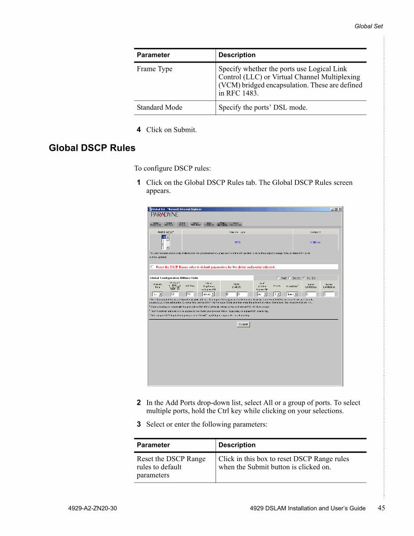
Global DSCP Rules
To configure DSCP rules:
1 Click on the Global DSCP Rules tab. The Global DSCP Rules screen appears.
2 In the Add Ports drop-down list, select All or a group of ports. To select multiple ports, hold the Ctrl key while clicking on your selections.
3 Select or enter the following parameters:
Frame Type Specify whether the ports use Logical Link Control (LLC) or Virtual Channel Multiplexing (VCM) bridged encapsulation. These are defined in RFC 1483.
Standard Mode Specify the ports’ DSL mode.
Parameter Description
Parameter Description
Reset the DSCP Range rules to default parameters
Click in this box to reset DSCP Range rules when the Submit button is clicked on.
Configuration Using the NMS
46 4929 DSLAM Installation and User’s Guide 4929-A2-ZN20-30
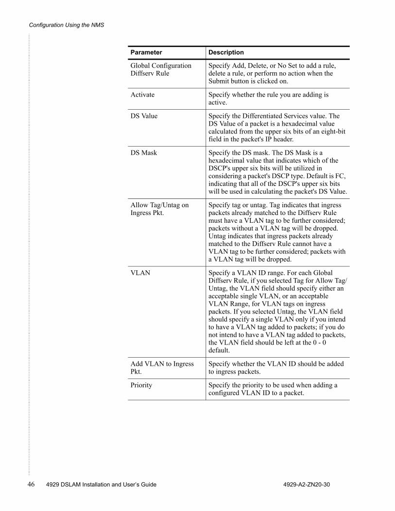
Global Configuration Diffserv Rule
Specify Add, Delete, or No Set to add a rule, delete a rule, or perform no action when the Submit button is clicked on.
Activate Specify whether the rule you are adding is active.
DS Value Specify the Differentiated Services value. The DS Value of a packet is a hexadecimal value calculated from the upper six bits of an eight-bit field in the packet's IP header.
DS Mask Specify the DS mask. The DS Mask is a hexadecimal value that indicates which of the DSCP's upper six bits will be utilized in considering a packet's DSCP type. Default is FC, indicating that all of the DSCP's upper six bits will be used in calculating the packet's DS Value.
Allow Tag/Untag on Ingress Pkt.
Specify tag or untag. Tag indicates that ingress packets already matched to the Diffserv Rule must have a VLAN tag to be further considered; packets without a VLAN tag will be dropped. Untag indicates that ingress packets already matched to the Diffserv Rule cannot have a VLAN tag to be further considered; packets with a VLAN tag will be dropped.
VLAN Specify a VLAN ID range. For each Global Diffserv Rule, if you selected Tag for Allow Tag/Untag, the VLAN field should specify either an acceptable single VLAN, or an acceptable VLAN Range, for VLAN tags on ingress packets. If you selected Untag, the VLAN field should specify a single VLAN only if you intend to have a VLAN tag added to packets; if you do not intend to have a VLAN tag added to packets, the VLAN field should be left at the 0 - 0 default.
Add VLAN to Ingress Pkt.
Specify whether the VLAN ID should be added to ingress packets.
Priority Specify the priority to be used when adding a configured VLAN ID to a packet.
Parameter Description
Global Set
4929-A2-ZN20-30 4929 DSLAM Installation and User’s Guide 47
4 Click on Submit.
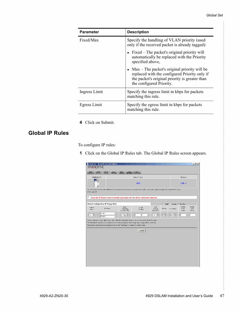
Global IP Rules
To configure IP rules:
1 Click on the Global IP Rules tab. The Global IP Rules screen appears.
Fixed/Max Specify the handling of VLAN priority (used only if the received packet is already tagged):
Fixed – The packet's original priority will automatically be replaced with the Priority specified above,
Max – The packet's original priority will be replaced with the configured Priority only if the packet's original priority is greater than the configured Priority.
Ingress Limit Specify the ingress limit in kbps for packets matching this rule.
Egress Limit Specify the egress limit in kbps for packets matching this rule.
Parameter Description

Configuration Using the NMS
48 4929 DSLAM Installation and User’s Guide 4929-A2-ZN20-30
2 In the Add Ports drop-down list, select All or a group of ports. To select multiple ports, hold the Ctrl key while clicking on your selections.
3 Select or enter the following parameters:
Parameter Description
Reset the IP Range rules to default parameters
Click in this box to reset IP Range rules when the Submit button is clicked on.
Global Configuration IP Range Rule
Specify Add, Delete, or No Set to add a rule, delete a rule, or perform no action when the Submit button is clicked on.
Activate Specify whether the rule you are adding is active.
IP Range Specify the range of IP addresses that constitutes a match for this rule.
Allow Tag/Untag on Ingress Pkt.
Specify tag or untag. Tag indicates that ingress packets already matched to the IP Rule must have a VLAN tag to be further considered; packets without a VLAN tag will be dropped. Untag indicates that ingress packets already matched to the IP Rule cannot have a VLAN tag to be further considered; packets with a VLAN tag will be dropped.
VLAN Specify a VLAN ID range. For each Global IP Range Rule, if you selected Tag for Allow Tag/Untag, the VLAN field should specify either an acceptable single VLAN, or an acceptable VLAN Range, for VLAN tags on ingress packets. If you selected Untag, the VLAN field should specify a single VLAN only if you intend to have a VLAN tag added to packets; if you do not intend to have a VLAN tag added to packets, the VLAN field should be left at the 0 - 0 default.
Add VLAN to Ingress Pkt.
Specify whether the VLAN ID should be added to ingress packets.
Priority Specify the priority to be used when adding a configured VLAN ID to a packet.
Global Set
4929-A2-ZN20-30 4929 DSLAM Installation and User’s Guide 49
4 Click on Submit.
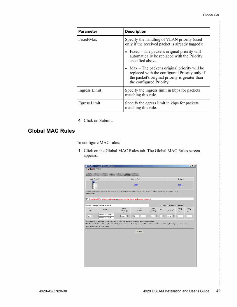
Global MAC Rules
To configure MAC rules:
1 Click on the Global MAC Rules tab. The Global MAC Rules screen appears.
Fixed/Max Specify the handling of VLAN priority (used only if the received packet is already tagged):
Fixed – The packet's original priority will automatically be replaced with the Priority specified above,
Max – The packet's original priority will be replaced with the configured Priority only if the packet's original priority is greater than the configured Priority.
Ingress Limit Specify the ingress limit in kbps for packets matching this rule.
Egress Limit Specify the egress limit in kbps for packets matching this rule.
Parameter Description
Configuration Using the NMS
50 4929 DSLAM Installation and User’s Guide 4929-A2-ZN20-30
2 In the Add Ports drop-down list, select All or a group of ports. To select multiple ports, hold the Ctrl key while clicking on your selections.
3 Select or enter the following parameters:
Parameter Description
Reset the MAC rules to default parameters
Click in this box to reset MAC rules when the Submit button is clicked on.
Global Configuration IP Range Rule
Specify Add, Delete, or No Set to add a rule, delete a rule, or perform no action when the Submit button is clicked on.
Activate Specify whether the rule you are adding is active.
MAC Range Specify the range of MAC addresses that constitutes a match for this rule.
Allow Tag/Untag on Ingress Pkt.
Specify tag or untag. Tag indicates that ingress packets already matched to the MAC Rule must have a VLAN tag to be further considered; packets without a VLAN tag will be dropped. Untag indicates that ingress packets already matched to the MAC Rule cannot have a VLAN tag to be further considered; packets with a VLAN tag will be dropped.
VLAN Specify a VLAN ID range. For each Global MAC Rule, if you selected Tag for Allow Tag/Untag, the VLAN field should specify either an acceptable single VLAN, or an acceptable VLAN Range, for VLAN tags on ingress packets. If you selected Untag, the VLAN field should specify a single VLAN only if you intend to have a VLAN tag added to packets; if you do not intend to have a VLAN tag added to packets, the VLAN field should be left at the 0 - 0 default.
Add VLAN to Ingress Pkt.
Specify whether the VLAN ID should be added to ingress packets.
Priority Specify the priority to be used when adding a configured VLAN ID to a packet.

Global Set
4929-A2-ZN20-30 4929 DSLAM Installation and User’s Guide 51
4 Click on Submit.
Global VLAN Rules
To configure VLAN rules:
1 Click on the Global VLAN Rules tab. The Global VLAN Rules screen appears.
Fixed/Max Specify the handling of VLAN priority (used only if the received packet is already tagged):
Fixed – The packet's original priority will automatically be replaced with the Priority specified above,
Max – The packet's original priority will be replaced with the configured Priority only if the packet's original priority is greater than the configured Priority.
Ingress Limit Specify the ingress limit in kbps for packets matching this rule.
Egress Limit Specify the egress limit in kbps for packets matching this rule.
Parameter Description
Configuration Using the NMS
52 4929 DSLAM Installation and User’s Guide 4929-A2-ZN20-30
2 In the Add Ports drop-down list, select All or a group of ports. To select multiple ports, hold the Ctrl key while clicking on your selections.
3 Select or enter the following parameters:
Parameter Description
Reset the VLAN rules to default parameters
Click in this box to reset VLAN rules when the Submit button is clicked on.
Global Configuration VLAN Rule
Specify Add, Delete, or No Set to add a rule, delete a rule, or perform no action when the Submit button is clicked on.
Activate Specify whether the rule you are adding is active.
Allow Tag/Untag on Ingress Pkt.
Specify tag or untag.
The DSLAM tries to match to a VLAN rule traffic that has not matched any other rule type. If the packet is untagged it will match the one and only allowed VLAN rule that indicates Untagged. If the packet has a tag then the DSLAM will try to find a Tagged rule that has a VLAN range defined with the packet’s VLAN ID. If it finds one it will use that rule, and then the packet will be checked for all other criteria. If it does not find a rule to match the packet VLAN ID the packet is dropped.
VLAN Specify a VLAN ID range that constitutes a match of this rule. If you selected Untag, the VLAN field should specify a single VLAN only if you intend to have a VLAN tag added to packets; if you do not intend to have a VLAN tag added to packets, the VLAN field should be left at the 0 - 0 default.
Add VLAN to Ingress Pkt.
Specify whether the VLAN ID should be added to ingress packets.
Priority Specify the priority to be used when adding a configured VLAN ID to a packet.
Fixed/Max Specify the handling of VLAN priority (used only if the received packet is already tagged):
Fixed – The packet's original priority will automatically be replaced with the Priority specified above,
Max – The packet's original priority will be replaced with the configured Priority only if the packet's original priority is greater than the configured Priority.
Global Set
4929-A2-ZN20-30 4929 DSLAM Installation and User’s Guide 53
4 Click on Submit.
Ingress Limit Specify the ingress limit in kbps for packets matching this rule.
Egress Limit Specify the egress limit in kbps for packets matching this rule.
Parameter Description
Configuration Using the NMS
54 4929 DSLAM Installation and User’s Guide 4929-A2-ZN20-30
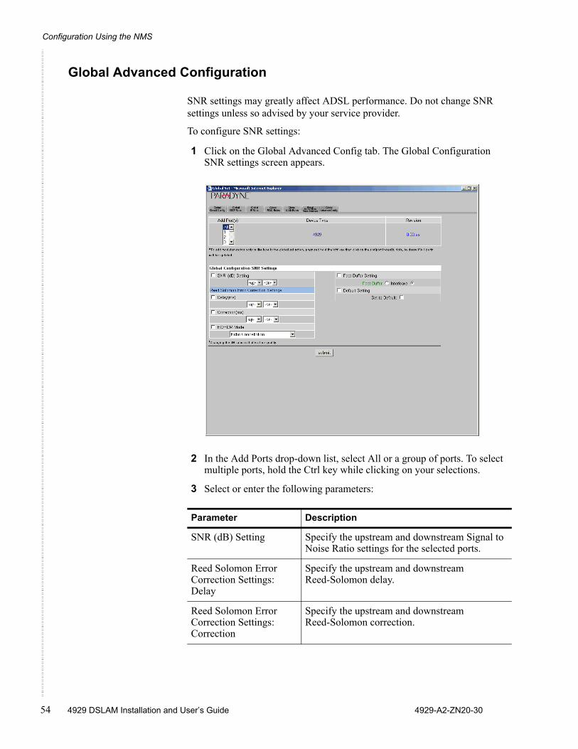
Global Advanced Configuration
SNR settings may greatly affect ADSL performance. Do not change SNR settings unless so advised by your service provider.
To configure SNR settings:
1 Click on the Global Advanced Config tab. The Global Configuration SNR settings screen appears.
2 In the Add Ports drop-down list, select All or a group of ports. To select multiple ports, hold the Ctrl key while clicking on your selections.
3 Select or enter the following parameters:
Parameter Description
SNR (dB) Setting Specify the upstream and downstream Signal to Noise Ratio settings for the selected ports.
Reed Solomon Error Correction Settings: Delay
Specify the upstream and downstream Reed-Solomon delay.
Reed Solomon Error Correction Settings: Correction
Specify the upstream and downstream Reed-Solomon correction.
Circuit Summary
4929-A2-ZN20-30 4929 DSLAM Installation and User’s Guide 55
4 Click on Submit.
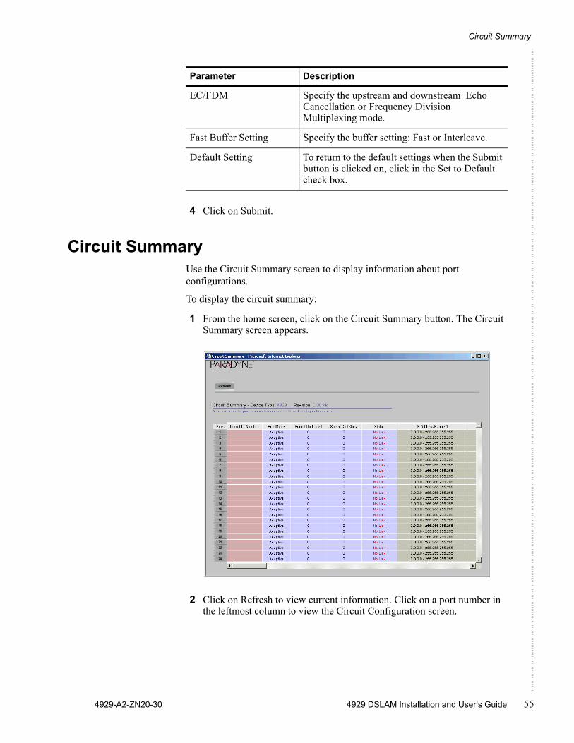
Circuit SummaryUse the Circuit Summary screen to display information about port configurations.
To display the circuit summary:
1 From the home screen, click on the Circuit Summary button. The Circuit Summary screen appears.
2 Click on Refresh to view current information. Click on a port number in the leftmost column to view the Circuit Configuration screen.
EC/FDM Specify the upstream and downstream Echo Cancellation or Frequency Division Multiplexing mode.
Fast Buffer Setting Specify the buffer setting: Fast or Interleave.
Default Setting To return to the default settings when the Submit button is clicked on, click in the Set to Default check box.
Parameter Description
Configuration Using the NMS
56 4929 DSLAM Installation and User’s Guide 4929-A2-ZN20-30
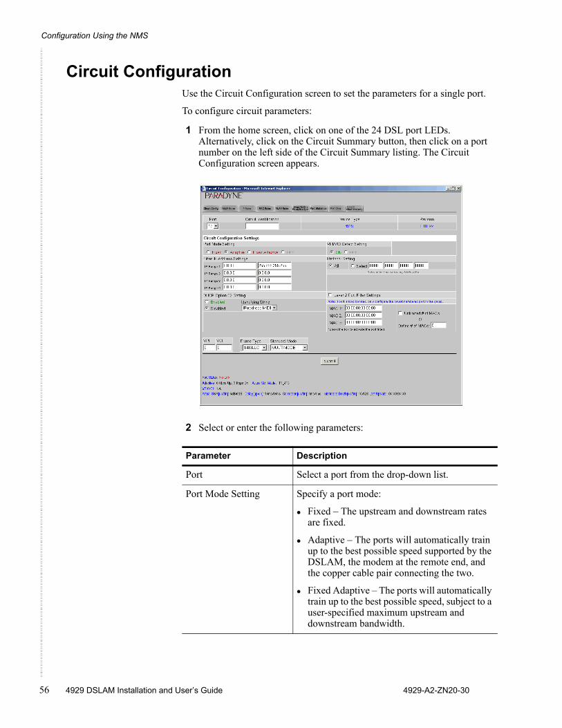
Circuit ConfigurationUse the Circuit Configuration screen to set the parameters for a single port.
To configure circuit parameters:
1 From the home screen, click on one of the 24 DSL port LEDs. Alternatively, click on the Circuit Summary button, then click on a port number on the left side of the Circuit Summary listing. The Circuit Configuration screen appears.
2 Select or enter the following parameters:
Parameter Description
Port Select a port from the drop-down list.
Port Mode Setting Specify a port mode:
Fixed – The upstream and downstream rates are fixed.
Adaptive – The ports will automatically train up to the best possible speed supported by the DSLAM, the modem at the remote end, and the copper cable pair connecting the two.
Fixed Adaptive – The ports will automatically train up to the best possible speed, subject to a user-specified maximum upstream and downstream bandwidth.
Circuit Configuration
4929-A2-ZN20-30 4929 DSLAM Installation and User’s Guide 57
3 Click on Submit.
VPI/VCI Detect Setting Specify the port behavior with regard to VPI/VCI detection:
On – The DSLAM will monitor the line to determine the VPI and VCI settings of the remote ADSL modem and set itself accordingly. If no ATM cells are detected (at any VPI/VCI setting), the port will default to VPI 0 and VCI 35.
Off – The port will use the default setting of VPI and VCI (0/35 if not changed by the setting of VPI and VCI, below), or lock in the VPI/VCI already discovered while VPI/VCI detection was On.
Filter IP Address Settings Specify up to four IP address ranges. Packets are accepted from source IP addresses in the ranges specified.
Protocol Setting Click in the check box to enable Protocol Setting detection. Select Allow Selected and specify up to four Ethertypes allowed on the ports.
DHCP Option 82 Specify whether DHCP Option 82 is enabled, and if it is, whether packets are identified by IP address or circuit ID. This identifier is added to packets to let your DHCP Server recognize which DSLAM port an IP address request is coming from, thereby allowing the DHCP Server to limit the number of IP addresses assigned per port.
Layer 2 Port Filter Settings
Click in the check box if you want to filter by MAC address the packets on this port.
MAC 1 – MAC 3 Enter up to three MAC addresses.
Unlimited # of MACs or Define # of MACs
Specify whether the number of MAC addresses with access to the port is to be limited to a certain number (not including MAC 1, MAC 2, and MAC 3, if specified above).
VPI and VCI Specify a default VPI and VCI if VPI/VCI Detect Setting (above) is Off.
Frame Type Specify whether the ports use Logical Link Control (LLC) or Virtual Channel Multiplexing (VCM) bridged encapsulation. These are defined in RFC 1483.
Standard Mode Specify the ports’ DSL mode.
Parameter Description
Configuration Using the NMS
58 4929 DSLAM Installation and User’s Guide 4929-A2-ZN20-30
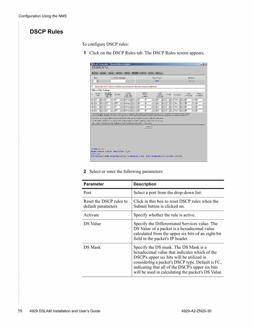
DSCP Rules
To configure DSCP rules:
1 Click on the DSCP Rules tab. The DSCP Rules screen appears.
2 Select or enter the following parameters:
Parameter Description
Port Select a port from the drop-down list.
Reset the DSCP rules to default parameters
Click in this box to reset DSCP rules when the Submit button is clicked on.
Activate Specify whether the rule is active.
DS Value Specify the Differentiated Services value. The DS Value of a packet is a hexadecimal value calculated from the upper six bits of an eight-bit field in the packet's IP header.
DS Mask Specify the DS mask. The DS Mask is a hexadecimal value that indicates which of the DSCP's upper six bits will be utilized in considering a packet's DSCP type. Default is FC, indicating that all of the DSCP's upper six bits will be used in calculating the packet's DS Value.
Circuit Configuration
4929-A2-ZN20-30 4929 DSLAM Installation and User’s Guide 59
3 Click on Submit.
Allow Tag/Untag on Ingress Pkt.
Specify tag or untag. Tag indicates that ingress packets already matched to the Diffserv Rule must have a VLAN tag to be further considered; packets without a VLAN tag will be dropped. Untag indicates that ingress packets already matched to the Diffserv Rule cannot have a VLAN tag to be further considered; packets with a VLAN tag will be dropped.
VLAN ID Range Specify a VLAN ID range. For each rule, if you selected Tag for Allow Tag/Untag, the VLAN field should specify either an acceptable single VLAN, or an acceptable VLAN Range, for VLAN tags on ingress packets. If you selected Untag, the VLAN field should specify a single VLAN only if you intend to have a VLAN tag added to packets; if you do not intend to have a VLAN tag added to packets, the VLAN field should be left at the 0 - 0 default.
Add VLAN to Ingress Pkt.
Specify whether the VLAN ID should be added to ingress packets.
Priority Specify the priority to be used when adding a configured VLAN ID to a packet.
Fixed/Max Specify the handling of VLAN priority (used only if the received packet is already tagged):
Fixed – The packet's original priority will automatically be replaced with the Priority specified above,
Max – The packet's original priority will be replaced with the configured Priority only if the packet's original priority is greater than the configured Priority.
Ingress Limit Specify the ingress limit in kbps for packets matching this rule.
Egress Limit Specify the egress limit in kbps for packets matching this rule.
Parameter Description
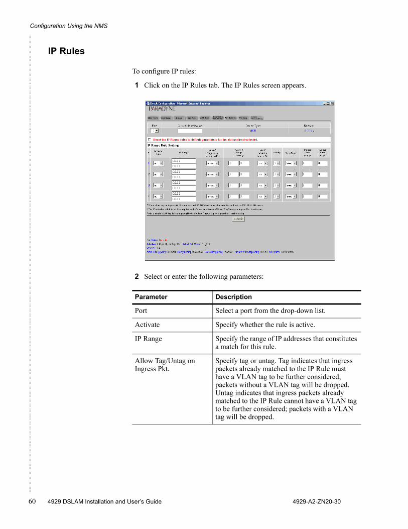
Configuration Using the NMS
60 4929 DSLAM Installation and User’s Guide 4929-A2-ZN20-30
IP Rules
To configure IP rules:
1 Click on the IP Rules tab. The IP Rules screen appears.
2 Select or enter the following parameters:
Parameter Description
Port Select a port from the drop-down list.
Activate Specify whether the rule is active.
IP Range Specify the range of IP addresses that constitutes a match for this rule.
Allow Tag/Untag on Ingress Pkt.
Specify tag or untag. Tag indicates that ingress packets already matched to the IP Rule must have a VLAN tag to be further considered; packets without a VLAN tag will be dropped. Untag indicates that ingress packets already matched to the IP Rule cannot have a VLAN tag to be further considered; packets with a VLAN tag will be dropped.
Circuit Configuration
4929-A2-ZN20-30 4929 DSLAM Installation and User’s Guide 61
3 Click on Submit.
VLAN ID Range Specify a VLAN ID range. For each IP Range Rule, if you selected Tag for Allow Tag/Untag, the VLAN field should specify either an acceptable single VLAN, or an acceptable VLAN Range, for VLAN tags on ingress packets. If you selected Untag, the VLAN field should specify a single VLAN only if you intend to have a VLAN tag added to packets; if you do not intend to have a VLAN tag added to packets, the VLAN field should be left at the 0 - 0 default.
Add VLAN to Ingress Pkt.
Specify whether the VLAN ID should be added to ingress packets.
Priority Specify the priority to be used when adding a configured VLAN ID to a packet.
Fixed/Max Specify the handling of VLAN priority (used only if the received packet is already tagged):
Fixed – The packet's original priority will automatically be replaced with the Priority specified above,
Max – The packet's original priority will be replaced with the configured Priority only if the packet's original priority is greater than the configured Priority.
Ingress Limit Specify the ingress limit in kbps for packets matching this rule.
Egress Limit Specify the egress limit in kbps for packets matching this rule.
Parameter Description
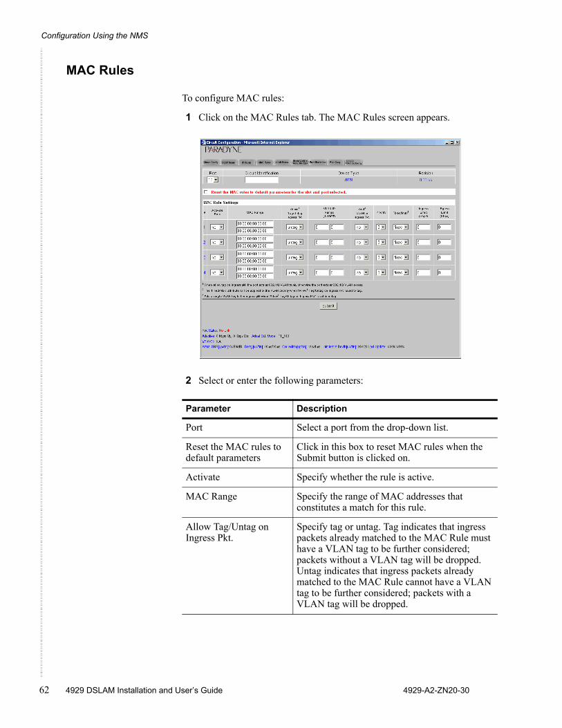
Configuration Using the NMS
62 4929 DSLAM Installation and User’s Guide 4929-A2-ZN20-30
MAC Rules
To configure MAC rules:
1 Click on the MAC Rules tab. The MAC Rules screen appears.
2 Select or enter the following parameters:
Parameter Description
Port Select a port from the drop-down list.
Reset the MAC rules to default parameters
Click in this box to reset MAC rules when the Submit button is clicked on.
Activate Specify whether the rule is active.
MAC Range Specify the range of MAC addresses that constitutes a match for this rule.
Allow Tag/Untag on Ingress Pkt.
Specify tag or untag. Tag indicates that ingress packets already matched to the MAC Rule must have a VLAN tag to be further considered; packets without a VLAN tag will be dropped. Untag indicates that ingress packets already matched to the MAC Rule cannot have a VLAN tag to be further considered; packets with a VLAN tag will be dropped.
Circuit Configuration
4929-A2-ZN20-30 4929 DSLAM Installation and User’s Guide 63
3 Click on Submit.
VLAN ID Range Specify a VLAN ID range. For each MAC Rule, if you selected Tag for Allow Tag/Untag, the VLAN field should specify either an acceptable single VLAN, or an acceptable VLAN Range, for VLAN tags on ingress packets. If you selected Untag, the VLAN field should specify a single VLAN only if you intend to have a VLAN tag added to packets; if you do not intend to have a VLAN tag added to packets, the VLAN field should be left at the 0 - 0 default.
Add VLAN to Ingress Pkt.
Specify whether the VLAN ID should be added to ingress packets.
Priority Specify the priority to be used when adding a configured VLAN ID to a packet.
Fixed/Max Specify the handling of VLAN priority (used only if the received packet is already tagged):
Fixed – The packet's original priority will automatically be replaced with the Priority specified above,
Max – The packet's original priority will be replaced with the configured Priority only if the packet's original priority is greater than the configured Priority.
Ingress Limit Specify the ingress limit in kbps for packets matching this rule.
Egress Limit Specify the egress limit in kbps for packets matching this rule.
Parameter Description
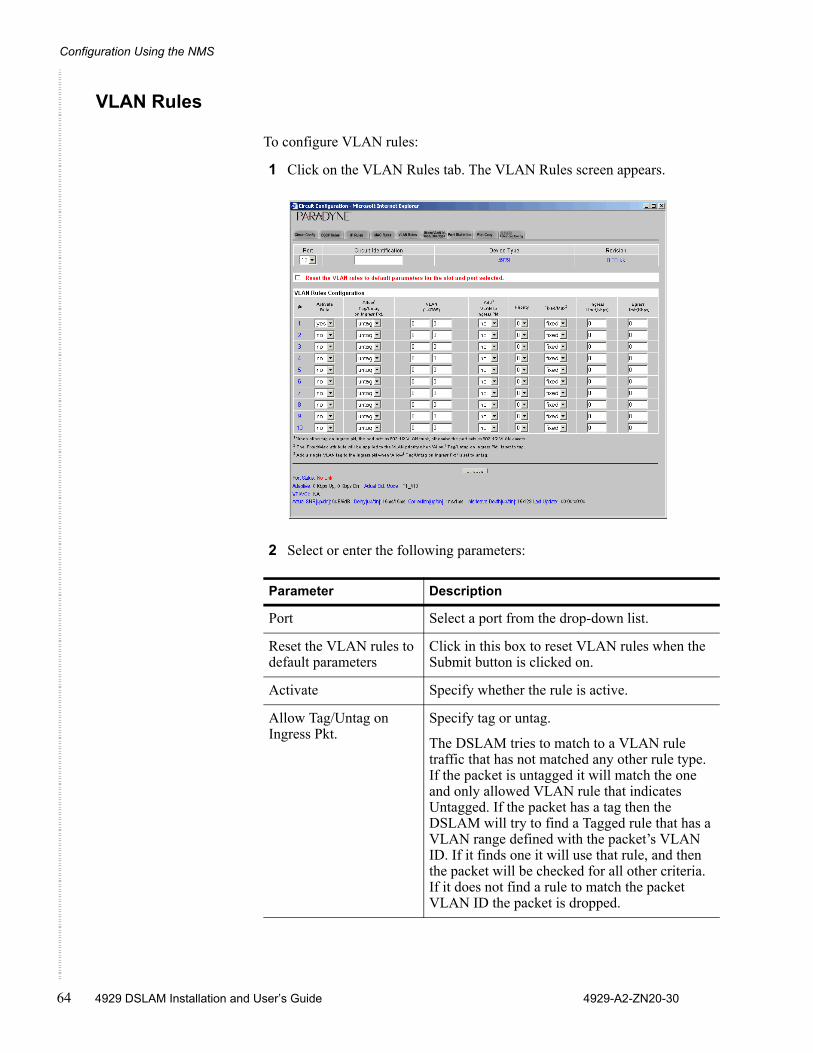
Configuration Using the NMS
64 4929 DSLAM Installation and User’s Guide 4929-A2-ZN20-30
VLAN Rules
To configure VLAN rules:
1 Click on the VLAN Rules tab. The VLAN Rules screen appears.
2 Select or enter the following parameters:
Parameter Description
Port Select a port from the drop-down list.
Reset the VLAN rules to default parameters
Click in this box to reset VLAN rules when the Submit button is clicked on.
Activate Specify whether the rule is active.
Allow Tag/Untag on Ingress Pkt.
Specify tag or untag.
The DSLAM tries to match to a VLAN rule traffic that has not matched any other rule type. If the packet is untagged it will match the one and only allowed VLAN rule that indicates Untagged. If the packet has a tag then the DSLAM will try to find a Tagged rule that has a VLAN range defined with the packet’s VLAN ID. If it finds one it will use that rule, and then the packet will be checked for all other criteria. If it does not find a rule to match the packet VLAN ID the packet is dropped.
Circuit Configuration
4929-A2-ZN20-30 4929 DSLAM Installation and User’s Guide 65
3 Click on Submit.
VLAN Specify a VLAN ID range that constitutes a match of this rule. If you selected Untag, the VLAN field should specify a single VLAN only if you intend to have a VLAN tag added to packets; if you do not intend to have a VLAN tag added to packets, the VLAN field should be left at the 0 - 0 default.
Add VLAN to Ingress Pkt.
Specify whether the VLAN ID should be added to ingress packets.
Priority Specify the priority to be used when adding a configured VLAN ID to a packet.
Fixed/Max Specify the handling of VLAN priority (used only if the received packet is already tagged):
Fixed – The packet's original priority will automatically be replaced with the Priority specified above,
Max – The packet's original priority will be replaced with the configured Priority only if the packet's original priority is greater than the configured Priority.
Ingress Limit Specify the ingress limit in kbps for packets matching this rule.
Egress Limit Specify the egress limit in kbps for packets matching this rule.
Parameter Description
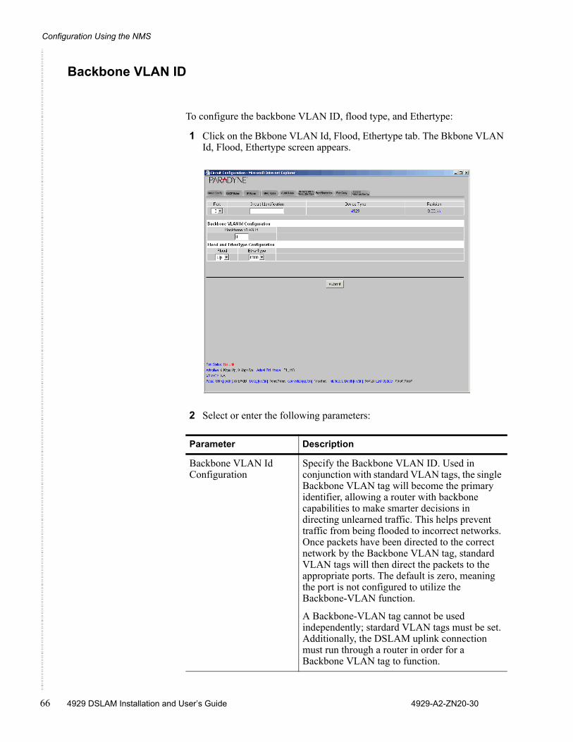
Configuration Using the NMS
66 4929 DSLAM Installation and User’s Guide 4929-A2-ZN20-30
Backbone VLAN ID
To configure the backbone VLAN ID, flood type, and Ethertype:
1 Click on the Bkbone VLAN Id, Flood, Ethertype tab. The Bkbone VLAN Id, Flood, Ethertype screen appears.
2 Select or enter the following parameters:
Parameter Description
Backbone VLAN Id Configuration
Specify the Backbone VLAN ID. Used in conjunction with standard VLAN tags, the single Backbone VLAN tag will become the primary identifier, allowing a router with backbone capabilities to make smarter decisions in directing unlearned traffic. This helps prevent traffic from being flooded to incorrect networks. Once packets have been directed to the correct network by the Backbone VLAN tag, standard VLAN tags will then direct the packets to the appropriate ports. The default is zero, meaning the port is not configured to utilize the Backbone-VLAN function.
A Backbone-VLAN tag cannot be used independently; stardard VLAN tags must be set. Additionally, the DSLAM uplink connection must run through a router in order for a Backbone VLAN tag to function.
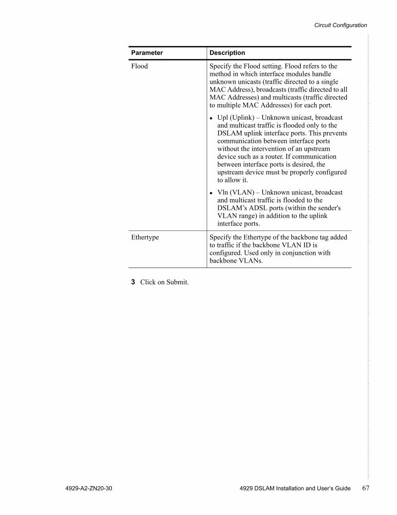
Circuit Configuration
4929-A2-ZN20-30 4929 DSLAM Installation and User’s Guide 67
3 Click on Submit.
Flood Specify the Flood setting. Flood refers to the method in which interface modules handle unknown unicasts (traffic directed to a single MAC Address), broadcasts (traffic directed to all MAC Addresses) and multicasts (traffic directed to multiple MAC Addresses) for each port.
Upl (Uplink) – Unknown unicast, broadcast and multicast traffic is flooded only to the DSLAM uplink interface ports. This prevents communication between interface ports without the intervention of an upstream device such as a router. If communication between interface ports is desired, the upstream device must be properly configured to allow it.
Vln (VLAN) – Unknown unicast, broadcast and multicast traffic is flooded to the DSLAM’s ADSL ports (within the sender's VLAN range) in addition to the uplink interface ports.
Ethertype Specify the Ethertype of the backbone tag added to traffic if the backbone VLAN ID is configured. Used only in conjunction with backbone VLANs.
Parameter Description
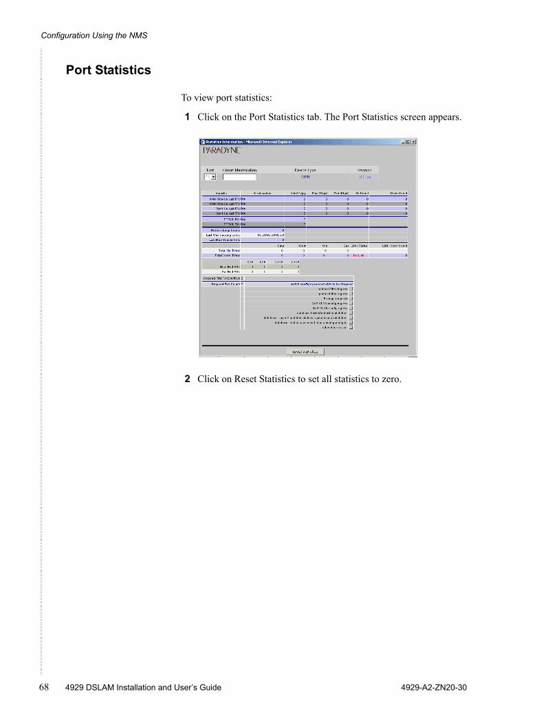
Configuration Using the NMS
68 4929 DSLAM Installation and User’s Guide 4929-A2-ZN20-30
Port Statistics
To view port statistics:
1 Click on the Port Statistics tab. The Port Statistics screen appears.
2 Click on Reset Statistics to set all statistics to zero.
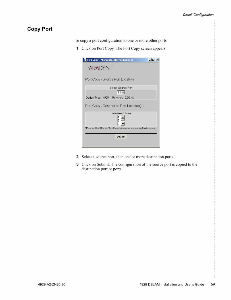
Circuit Configuration
4929-A2-ZN20-30 4929 DSLAM Installation and User’s Guide 69
Copy Port
To copy a port configuration to one or more other ports:
1 Click on Port Copy. The Port Copy screen appears.
2 Select a source port, then one or more destination ports.
3 Click on Submit. The configuration of the source port is copied to the destination port or ports.
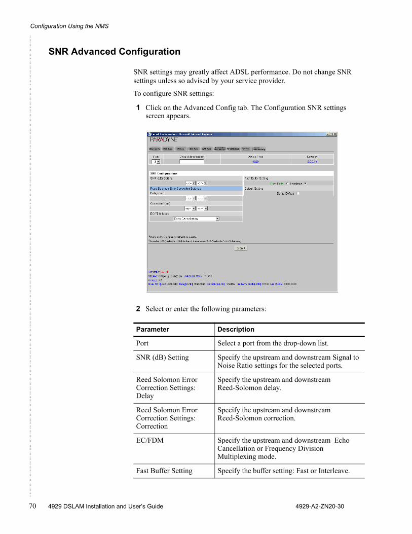
Configuration Using the NMS
70 4929 DSLAM Installation and User’s Guide 4929-A2-ZN20-30
SNR Advanced Configuration
SNR settings may greatly affect ADSL performance. Do not change SNR settings unless so advised by your service provider.
To configure SNR settings:
1 Click on the Advanced Config tab. The Configuration SNR settings screen appears.
2 Select or enter the following parameters:
Parameter Description
Port Select a port from the drop-down list.
SNR (dB) Setting Specify the upstream and downstream Signal to Noise Ratio settings for the selected ports.
Reed Solomon Error Correction Settings: Delay
Specify the upstream and downstream Reed-Solomon delay.
Reed Solomon Error Correction Settings: Correction
Specify the upstream and downstream Reed-Solomon correction.
EC/FDM Specify the upstream and downstream Echo Cancellation or Frequency Division Multiplexing mode.
Fast Buffer Setting Specify the buffer setting: Fast or Interleave.
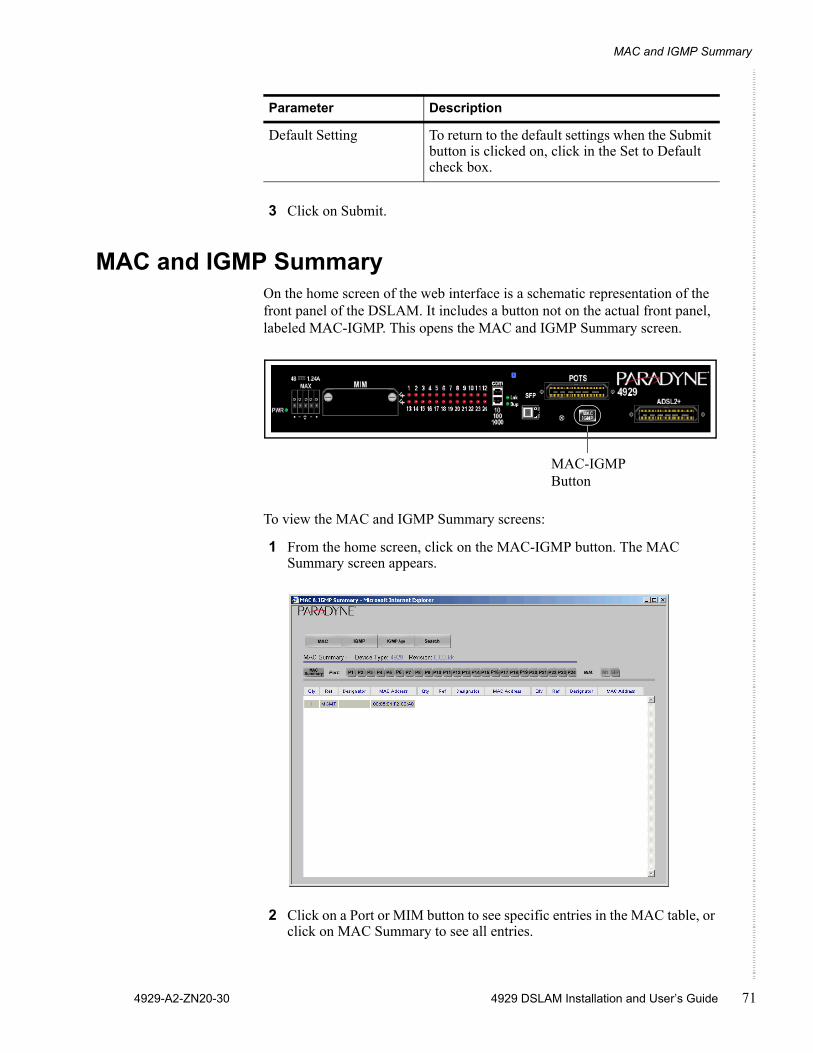
MAC and IGMP Summary
4929-A2-ZN20-30 4929 DSLAM Installation and User’s Guide 71
3 Click on Submit.
MAC and IGMP SummaryOn the home screen of the web interface is a schematic representation of the front panel of the DSLAM. It includes a button not on the actual front panel, labeled MAC-IGMP. This opens the MAC and IGMP Summary screen.
To view the MAC and IGMP Summary screens:
1 From the home screen, click on the MAC-IGMP button. The MAC Summary screen appears.
2 Click on a Port or MIM button to see specific entries in the MAC table, or click on MAC Summary to see all entries.
Default Setting To return to the default settings when the Submit button is clicked on, click in the Set to Default check box.
Parameter Description
MAC-IGMP Button
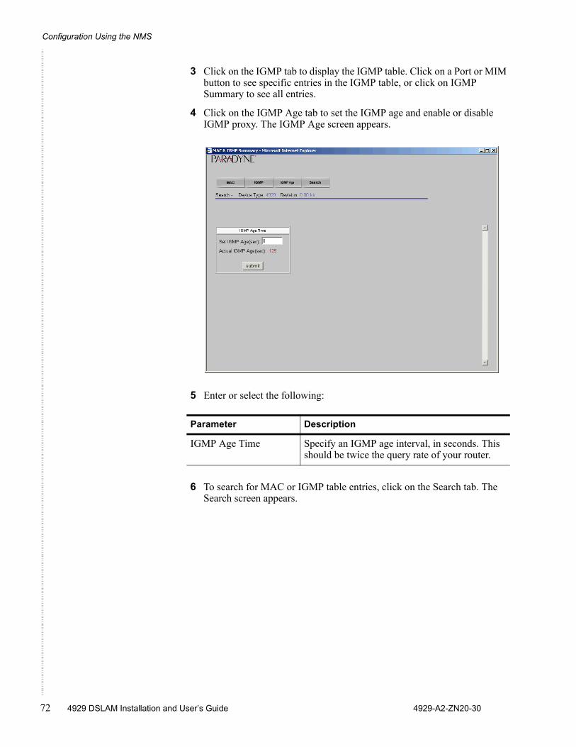
Configuration Using the NMS
72 4929 DSLAM Installation and User’s Guide 4929-A2-ZN20-30
3 Click on the IGMP tab to display the IGMP table. Click on a Port or MIM button to see specific entries in the IGMP table, or click on IGMP Summary to see all entries.
4 Click on the IGMP Age tab to set the IGMP age and enable or disable IGMP proxy. The IGMP Age screen appears.
5 Enter or select the following:
6 To search for MAC or IGMP table entries, click on the Search tab. The Search screen appears.
Parameter Description
IGMP Age Time Specify an IGMP age interval, in seconds. This should be twice the query rate of your router.
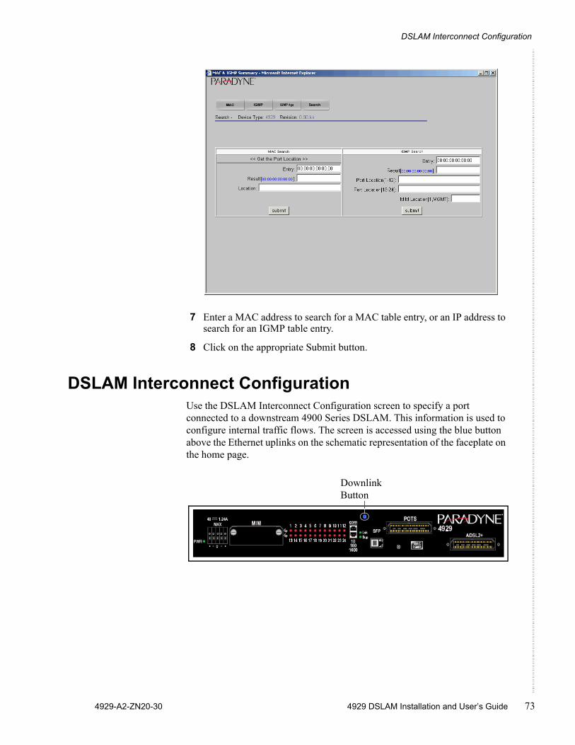
DSLAM Interconnect Configuration
4929-A2-ZN20-30 4929 DSLAM Installation and User’s Guide 73
7 Enter a MAC address to search for a MAC table entry, or an IP address to search for an IGMP table entry.
8 Click on the appropriate Submit button.
DSLAM Interconnect ConfigurationUse the DSLAM Interconnect Configuration screen to specify a port connected to a downstream 4900 Series DSLAM. This information is used to configure internal traffic flows. The screen is accessed using the blue button above the Ethernet uplinks on the schematic representation of the faceplate on the home page.
Downlink Button
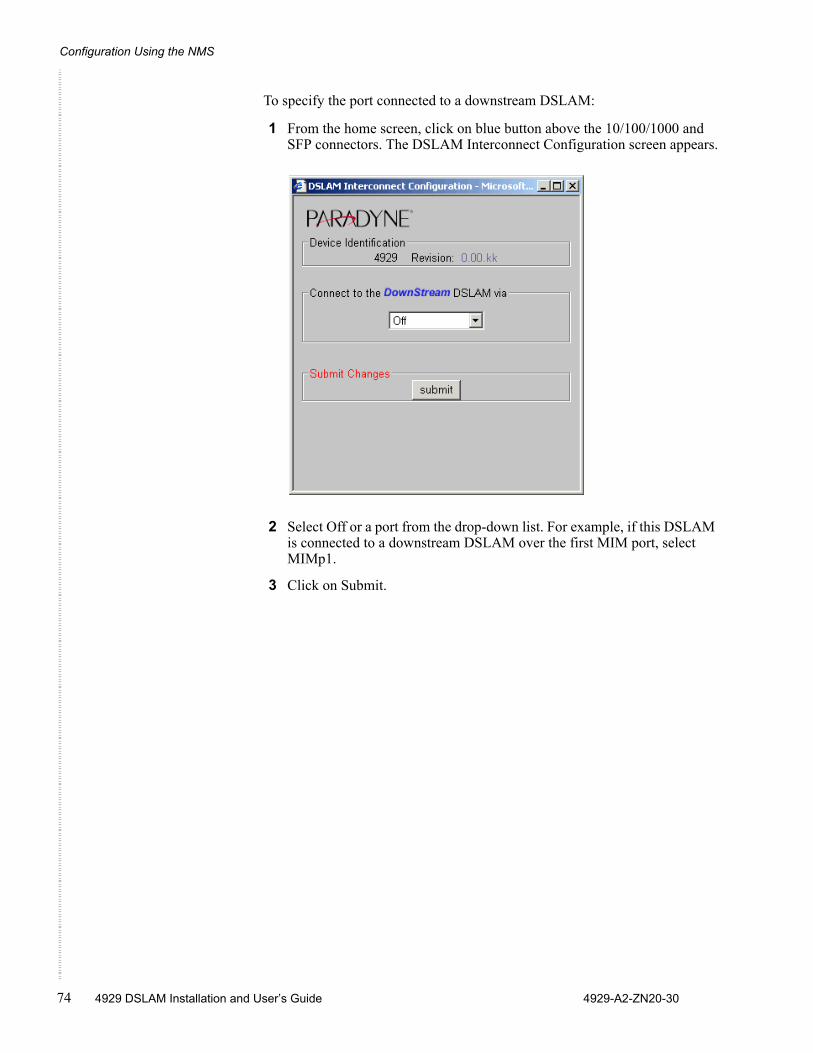
Configuration Using the NMS
74 4929 DSLAM Installation and User’s Guide 4929-A2-ZN20-30
To specify the port connected to a downstream DSLAM:
1 From the home screen, click on blue button above the 10/100/1000 and SFP connectors. The DSLAM Interconnect Configuration screen appears.
2 Select Off or a port from the drop-down list. For example, if this DSLAM is connected to a downstream DSLAM over the first MIM port, select MIMp1.
3 Click on Submit.
4929-A2-ZN20-30 4929 DSLAM Installation and User’s Guide 75
COMMAND LINE INTERFACE
OverviewThe 4900 Series DSLAMs have an integral command line interface (CLI) that can be accessed by direct connection to the COM port or by Telnet to the DSLAM’s management address.
CLI System RequirementsStraight-Through RJ45 to RJ45 Ethernet Cable – Required for establishing a direct connection from the COM port to a DB9 adapter.
DB9 Female to RJ45 Male Adapter – Required for conversion of your PC's RS232 serial port for use with the RJ45 to RJ45 Ethernet cable.
Terminal Emulation Program – Required for running the CLI over a direct connection. The program must emulate a VT100 terminal.
Telnet Client – Required for remote management with the CLI. Microsoft Windows Operating Systems (98, 2000, NT, and XP) include a Telnet client which is executed using the Windows command prompt (cmd.exe). If you are using an operating system other than Windows, you may need to install a Telnet client.
Connecting a PC DirectlyTo connect a PC directly to the DSLAM to use the CLI:
1 Plug a DB9 to RJ45 adapter into the RS232 serial port on your PC. See DB9 to RJ45 Adapter Pinouts in Appendix A, Connectors and Pin Assignments.
2 Connect one end of a straight-through RJ45 to RJ45 Ethernet cable into the adapter plugged into your PC, and the other end of the cable into the COM port on the face of the DSLAM.
Command Line Interface
76 4929 DSLAM Installation and User’s Guide 4929-A2-ZN20-30
Launching the Terminal Emulation ProgramLaunch the terminal emulation program on your PC and configure the program settings. Actual configurations will depend upon the program being used, though settings should be modeled after the list below; most are standard defaults. Refer to your terminal emulation program’s user manual for further information.
Logging Into the CLIOnce your terminal emulation program has been launched, device information is displayed, followed by a request for username and password. You must log in as a superuser in order to make configuration changes.
After you have logged in, enter a question mark (?) to list the available commands.
CLI CommandsThe CLI supports the following commands.
Baud: 9600 Port: Com 1
Data Bits: 8 Stop Bits: 1Flow Control:
none Transmit Delay:
n/a
Parity: none
Username: superuserPassword: Password
Table 3: CLI Commands (Sheet 1 of 2)
Command Description
? Lists available commands and their syntax.
ALLOW Controls by IP address those hosts for which traffic is permitted on the DSLAM. ALL (the default) permits all traffic.
Syntax:
allow [ALL, IP_ADDRESS [IP address]]
CLEAR_NVRAM Clears Non-Volatile Random Access Memory, restoring the DSLAM to factory defaults.
DISABLE_TELNET Disables access to the DSLAM using Telnet.
DISABLE_TFTP Disables access to the DSLAM using Trivial File Transfer Protocol.
CLI Commands
4929-A2-ZN20-30 4929 DSLAM Installation and User’s Guide 77
The commands use the following parameters.
DISABLE_WEB_SERVER] Disables access to the DSLAM using the web server.
ENABLE_TELNET Enables access to the DSLAM using Telnet.
ENABLE_TFTP Enables access to the DSLAM using Trivial File Transfer Protocol.
ENABLE_WEB_SERVER Enables access to the DSLAM using the web server.
HELP Lists available commands and their syntax.
LOGOUT Ends the CLI session.
SET Sets a configuration option. Most SET commands require that slot be specified, and allow port optionally to be specified. Exceptions are the two system SET commands for session timeout and system name.
Syntax:set cli_session_timeout seconds
set system_name name
set slot 1 [[port] [all, port_number]] [item] [value]
Items and values for SET commands are shown in Table 4, Set and Show Command Items and Values.
SHOW Shows a configuration option. SHOW commands require that slot be specified, and allow port optionally to be specified.
Syntax:show slot 1 [[port] [all, port_number]] [item] [value]
Items and values for SHOW commands are shown in Table 4, Set and Show Command Items and Values.
WHO Shows who is logged in the system.
Table 3: CLI Commands (Sheet 2 of 2)
Command Description
Table 4: Set and Show Command Items and Values (Sheet 1 of 3)
Items Values
ADSL_ENCAPSULATION [RFC1483-LLC,RFC1483-VCMUX]
ADSL_PORT_MODE [ON,OFF,ADAPTIVE,FIXED_ADAPTIVE]
ADSL_SPEED [XXXX YYYY]
Where: XXXX = downstream rate (in kbps) and YYYY = upstream rate (in kbps)
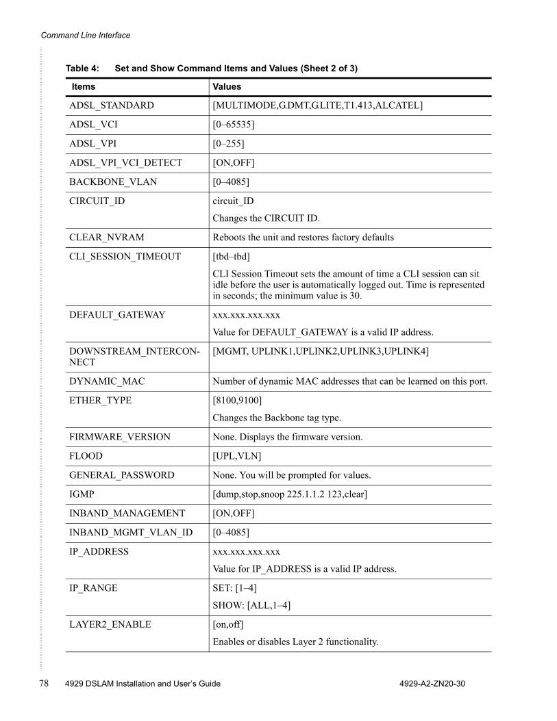
Command Line Interface
78 4929 DSLAM Installation and User’s Guide 4929-A2-ZN20-30
ADSL_STANDARD [MULTIMODE,G.DMT,G.LITE,T1.413,ALCATEL]
ADSL_VCI [0–65535]
ADSL_VPI [0–255]
ADSL_VPI_VCI_DETECT [ON,OFF]
BACKBONE_VLAN [0–4085]
CIRCUIT_ID circuit_ID
Changes the CIRCUIT ID.
CLEAR_NVRAM Reboots the unit and restores factory defaults
CLI_SESSION_TIMEOUT [tbd–tbd]
CLI Session Timeout sets the amount of time a CLI session can sit idle before the user is automatically logged out. Time is represented in seconds; the minimum value is 30.
DEFAULT_GATEWAY xxx.xxx.xxx.xxx
Value for DEFAULT_GATEWAY is a valid IP address.
DOWNSTREAM_INTERCON-NECT
[MGMT, UPLINK1,UPLINK2,UPLINK3,UPLINK4]
DYNAMIC_MAC Number of dynamic MAC addresses that can be learned on this port.
ETHER_TYPE [8100,9100]
Changes the Backbone tag type.
FIRMWARE_VERSION None. Displays the firmware version.
FLOOD [UPL,VLN]
GENERAL_PASSWORD None. You will be prompted for values.
IGMP [dump,stop,snoop 225.1.1.2 123,clear]
INBAND_MANAGEMENT [ON,OFF]
INBAND_MGMT_VLAN_ID [0–4085]
IP_ADDRESS xxx.xxx.xxx.xxx
Value for IP_ADDRESS is a valid IP address.
IP_RANGE SET: [1–4]
SHOW: [ALL,1–4]
LAYER2_ENABLE [on,off]
Enables or disables Layer 2 functionality.
Table 4: Set and Show Command Items and Values (Sheet 2 of 3)
Items Values
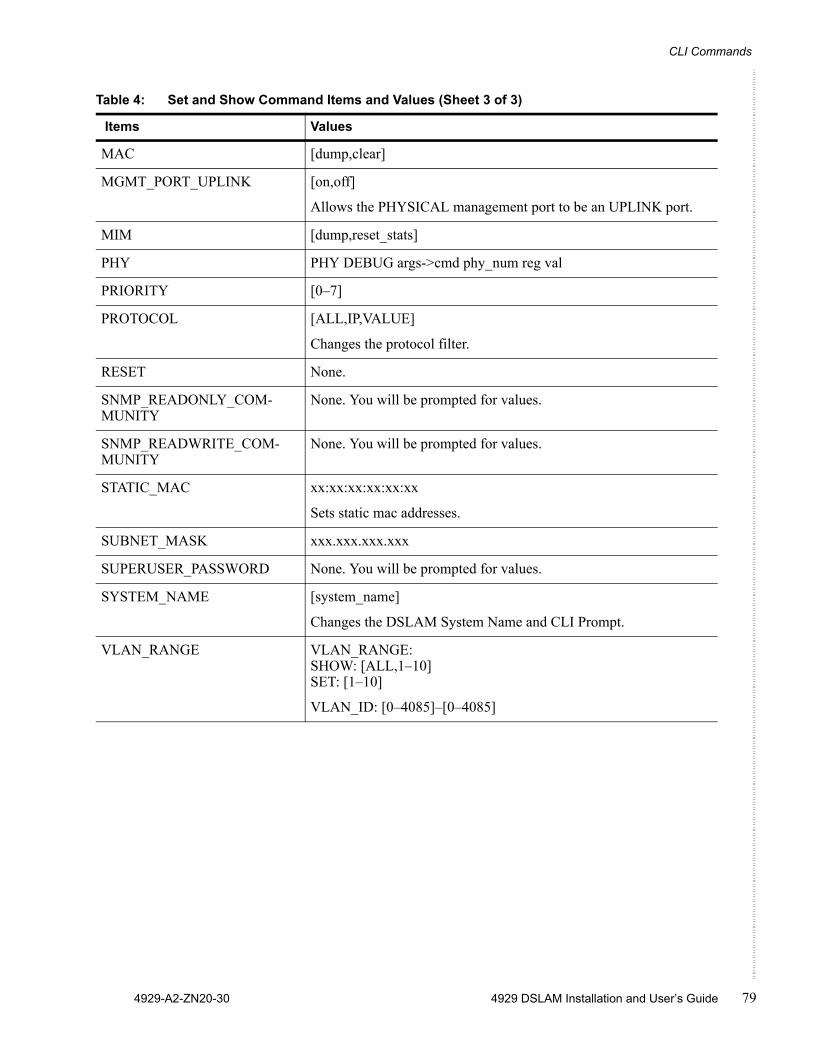
CLI Commands
4929-A2-ZN20-30 4929 DSLAM Installation and User’s Guide 79
MAC [dump,clear]
MGMT_PORT_UPLINK [on,off]
Allows the PHYSICAL management port to be an UPLINK port.
MIM [dump,reset_stats]
PHY PHY DEBUG args->cmd phy_num reg val
PRIORITY [0–7]
PROTOCOL [ALL,IP,VALUE]
Changes the protocol filter.
RESET None.
SNMP_READONLY_COM- MUNITY
None. You will be prompted for values.
SNMP_READWRITE_COM- MUNITY
None. You will be prompted for values.
STATIC_MAC xx:xx:xx:xx:xx:xx
Sets static mac addresses.
SUBNET_MASK xxx.xxx.xxx.xxx
SUPERUSER_PASSWORD None. You will be prompted for values.
SYSTEM_NAME [system_name]
Changes the DSLAM System Name and CLI Prompt.
VLAN_RANGE VLAN_RANGE: SHOW: [ALL,1–10]SET: [1–10]
VLAN_ID: [0–4085]–[0–4085]
Table 4: Set and Show Command Items and Values (Sheet 3 of 3)
Items Values
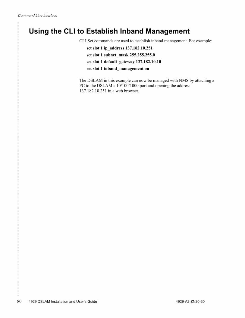
Command Line Interface
80 4929 DSLAM Installation and User’s Guide 4929-A2-ZN20-30
Using the CLI to Establish Inband ManagementCLI Set commands are used to establish inband management. For example:
set slot 1 ip_address 137.182.10.251set slot 1 subnet_mask 255.255.255.0set slot 1 default_gateway 137.182.10.10set slot 1 inband_management on
The DSLAM in this example can now be managed with NMS by attaching a PC to the DSLAM’s 10/100/1000 port and opening the address 137.182.10.251 in a web browser.
4929-A2-ZN20-30 4929 DSLAM Installation and User’s Guide 81
SNMP INTERFACE
OverviewThe 4900 Series DSLAM can be managed using the Simple Network Management Protocol (SNMP).
This implementation uses a portion of SNMP v1.0: the MIB-II System Group and Interfaces Group of OIDs. SNMP uses MIBs (Management Information Bases) sanctioned by the IETF (Internet Engineering Task Force). MIBs are composed of OIDs (Object Identifiers), each of which represents a system configuration or request for data.
You will not be able to manage your DSLAM via SNMP until you have set the unit IP address, subnet mask, and default gateway. See Management Configuration in Chapter 5, Configuration Using the NMS or Using the CLI to Establish Inband Management in Chapter 6, Command Line Interface.
Downloading MIBsYou must have a MIB browser installed on your PC in order to utilize the Management Information Base.
1 Launch your MIB browser and perform any necessary program configurations. Refer to your MIB browser user manual for further information.
2 Download the MIBs from the Zhone website. Refer to your MIB browser user manual for instructions on how to compile the OIDs into your MIB browser.
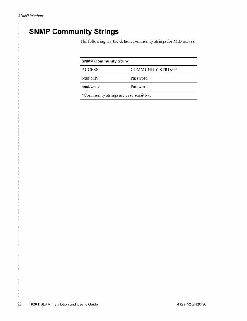
SNMP Interface
82 4929 DSLAM Installation and User’s Guide 4929-A2-ZN20-30
SNMP Community StringsThe following are the default community strings for MIB access.
SNMP Community String
ACCESS COMMUNITY STRING*
read only Password
read/write Password
*Community strings are case sensitive.
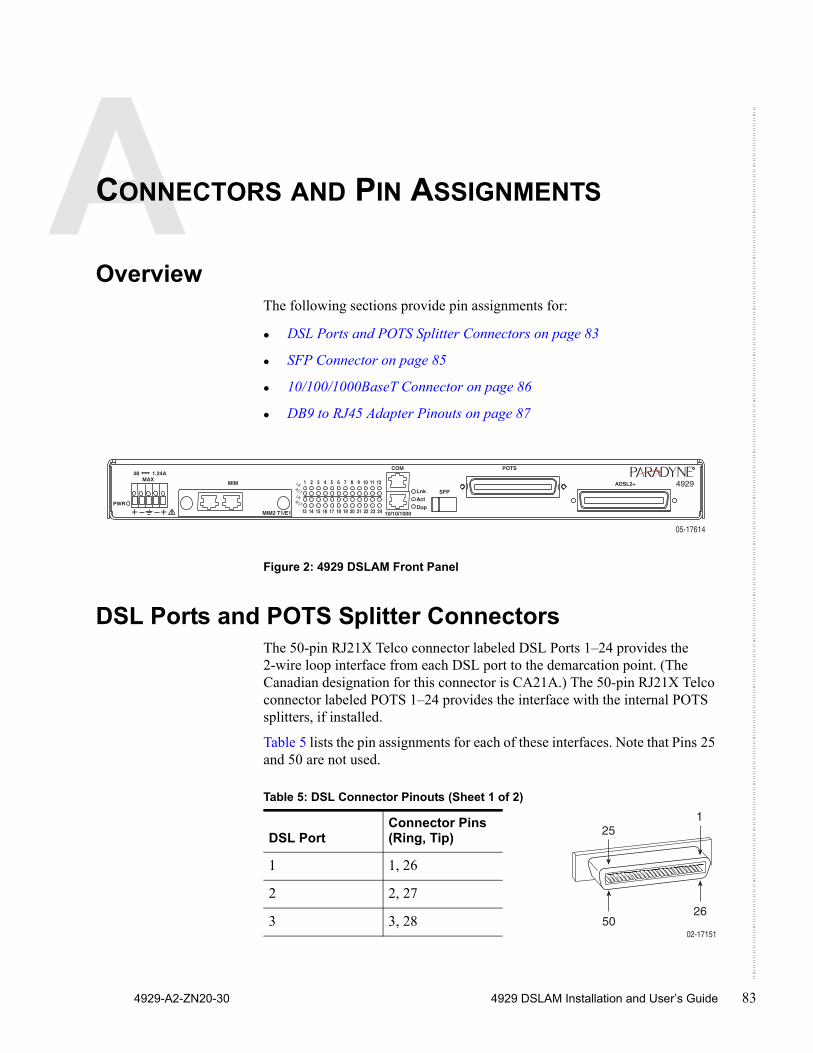
4929-A2-ZN20-30 4929 DSLAM Installation and User’s Guide 83
CONNECTORS AND PIN ASSIGNMENTS
OverviewThe following sections provide pin assignments for:
DSL Ports and POTS Splitter Connectors on page 83
SFP Connector on page 85
10/100/1000BaseT Connector on page 86
DB9 to RJ45 Adapter Pinouts on page 87
Figure 2: 4929 DSLAM Front Panel
DSL Ports and POTS Splitter ConnectorsThe 50-pin RJ21X Telco connector labeled DSL Ports 1–24 provides the 2-wire loop interface from each DSL port to the demarcation point. (The Canadian designation for this connector is CA21A.) The 50-pin RJ21X Telco connector labeled POTS 1–24 provides the interface with the internal POTS splitters, if installed.
Table 5 lists the pin assignments for each of these interfaces. Note that Pins 25 and 50 are not used.
����
�����
��������
��
� �������� � � � � � � � � � � � � � � �
��������������������������������������������
����������
���
���
���
�������������
���
����������
���
�
���
����
�
�
���
�
Table 5: DSL Connector Pinouts (Sheet 1 of 2)
DSL PortConnector Pins (Ring, Tip)
1 1, 26
2 2, 27
3 3, 28
25
02-17151
1
5026
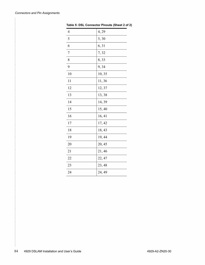
Connectors and Pin Assignments
84 4929 DSLAM Installation and User’s Guide 4929-A2-ZN20-30
4 4, 29
5 5, 30
6 6, 31
7 7, 32
8 8, 33
9 9, 34
10 10, 35
11 11, 36
12 12, 37
13 13, 38
14 14, 39
15 15, 40
16 16, 41
17 17, 42
18 18, 43
19 19, 44
20 20, 45
21 21, 46
22 22, 47
23 23, 48
24 24, 49
Table 5: DSL Connector Pinouts (Sheet 2 of 2)
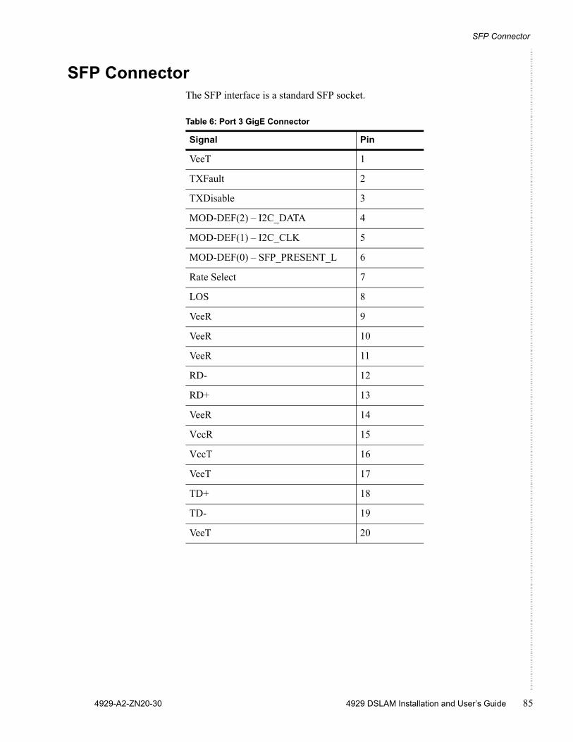
SFP Connector
4929-A2-ZN20-30 4929 DSLAM Installation and User’s Guide 85
SFP ConnectorThe SFP interface is a standard SFP socket.
Table 6: Port 3 GigE Connector
Signal Pin
VeeT 1
TXFault 2
TXDisable 3
MOD-DEF(2) – I2C_DATA 4
MOD-DEF(1) – I2C_CLK 5
MOD-DEF(0) – SFP_PRESENT_L 6
Rate Select 7
LOS 8
VeeR 9
VeeR 10
VeeR 11
RD- 12
RD+ 13
VeeR 14
VccR 15
VccT 16
VeeT 17
TD+ 18
TD- 19
VeeT 20
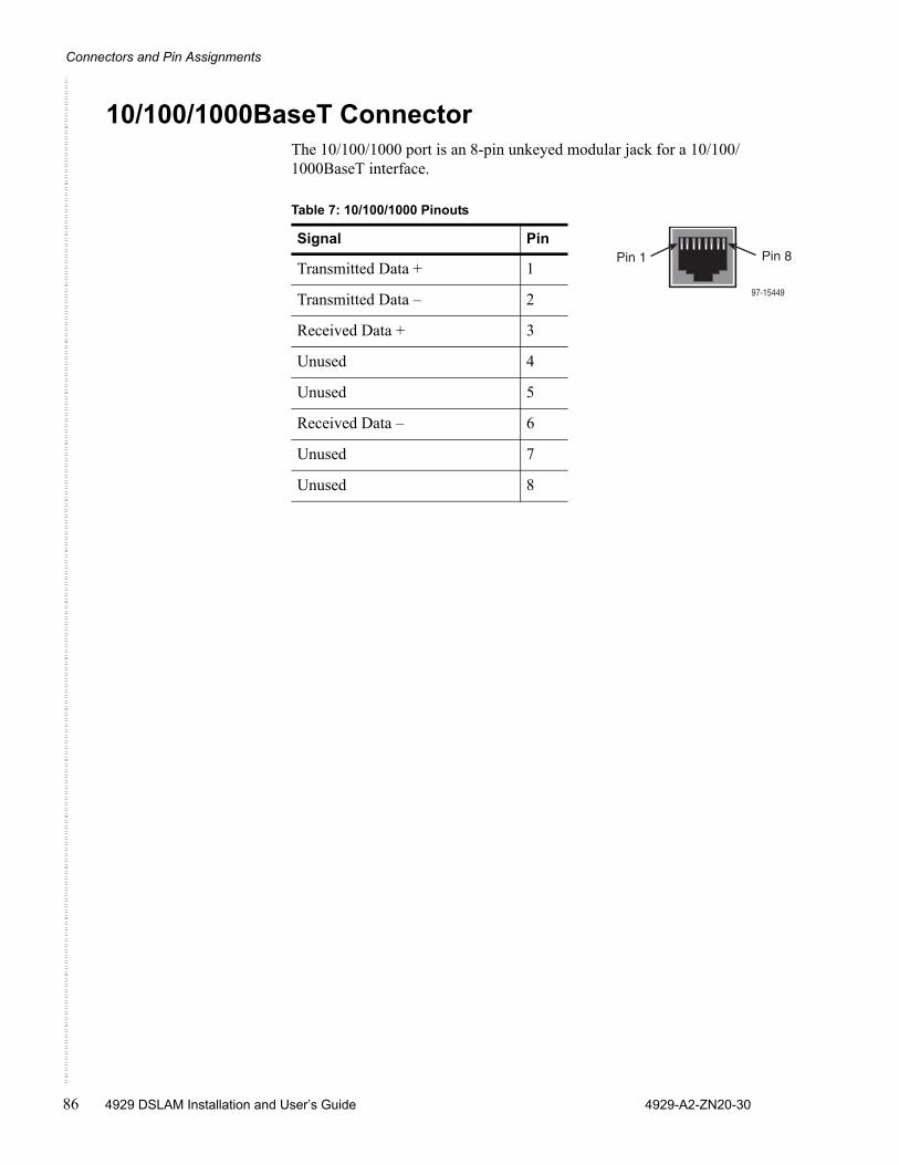
Connectors and Pin Assignments
86 4929 DSLAM Installation and User’s Guide 4929-A2-ZN20-30
10/100/1000BaseT ConnectorThe 10/100/1000 port is an 8-pin unkeyed modular jack for a 10/100/1000BaseT interface.
Table 7: 10/100/1000 Pinouts
Signal Pin
Transmitted Data + 1
Transmitted Data – 2
Received Data + 3
Unused 4
Unused 5
Received Data – 6
Unused 7
Unused 8
97-15449
Pin 1 Pin 8
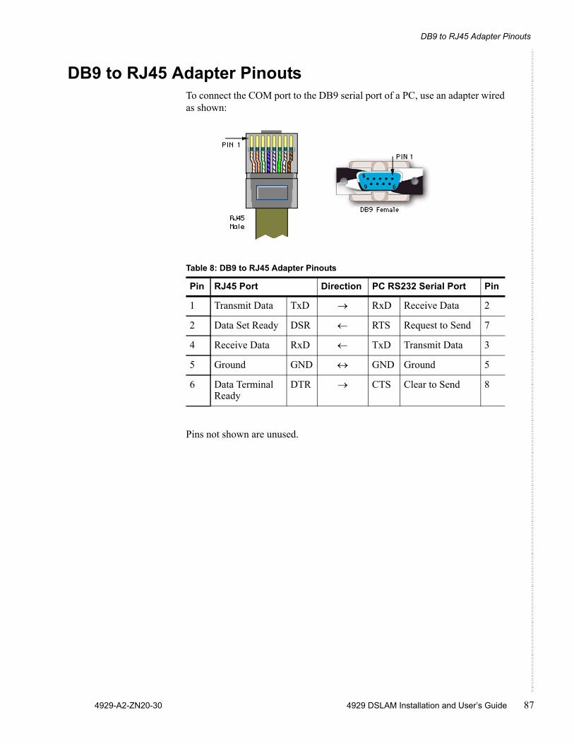
DB9 to RJ45 Adapter Pinouts
4929-A2-ZN20-30 4929 DSLAM Installation and User’s Guide 87
DB9 to RJ45 Adapter PinoutsTo connect the COM port to the DB9 serial port of a PC, use an adapter wired as shown:
Pins not shown are unused.
Table 8: DB9 to RJ45 Adapter Pinouts
Pin RJ45 Port Direction PC RS232 Serial Port Pin
1 Transmit Data TxD → RxD Receive Data 2
2 Data Set Ready DSR ← RTS Request to Send 7
4 Receive Data RxD ← TxD Transmit Data 3
5 Ground GND ↔ GND Ground 5
6 Data Terminal Ready
DTR → CTS Clear to Send 8

Connectors and Pin Assignments
88 4929 DSLAM Installation and User’s Guide 4929-A2-ZN20-30
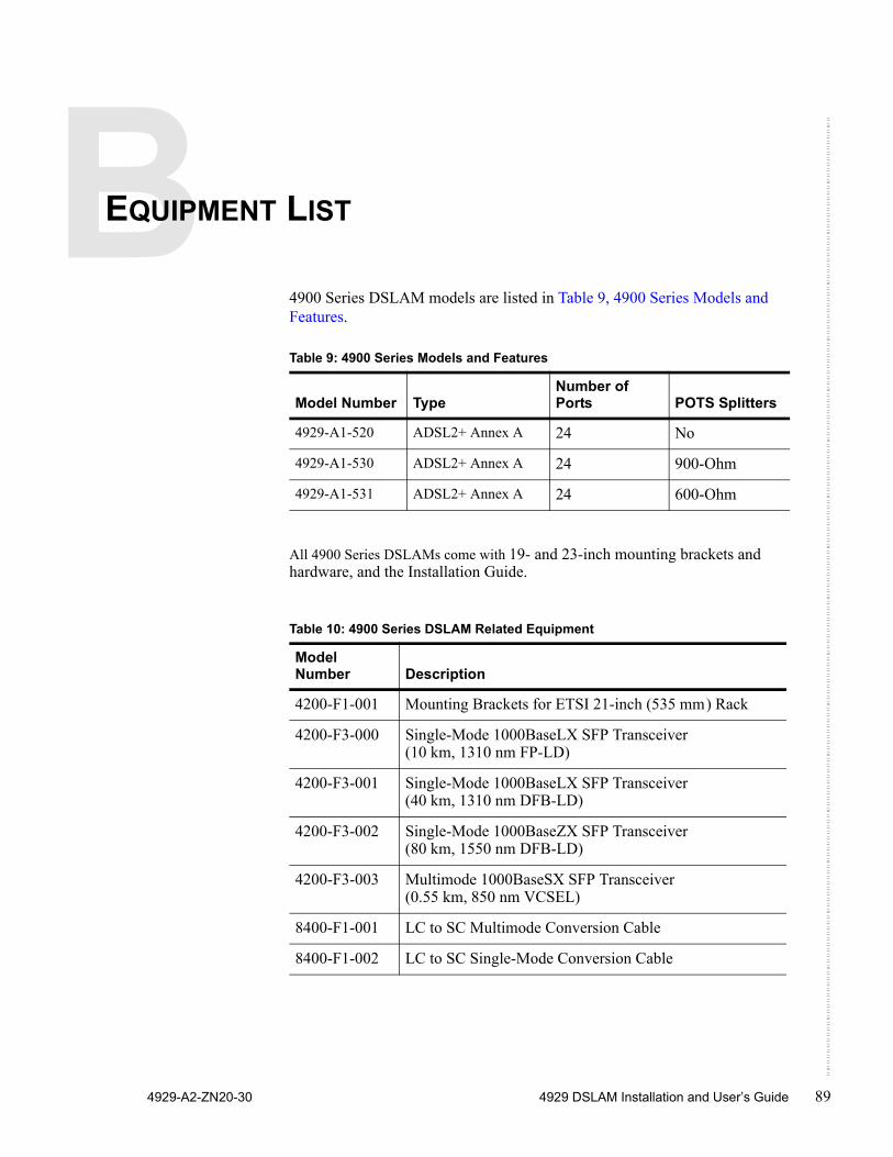
4929-A2-ZN20-30 4929 DSLAM Installation and User’s Guide 89
EQUIPMENT LIST
4900 Series DSLAM models are listed in Table 9, 4900 Series Models and Features.
All 4900 Series DSLAMs come with 19- and 23-inch mounting brackets and hardware, and the Installation Guide.
Table 9: 4900 Series Models and Features
Model Number TypeNumber of Ports POTS Splitters
4929-A1-520 ADSL2+ Annex A 24 No
4929-A1-530 ADSL2+ Annex A 24 900-Ohm
4929-A1-531 ADSL2+ Annex A 24 600-Ohm
Table 10: 4900 Series DSLAM Related Equipment
Model Number Description
4200-F1-001 Mounting Brackets for ETSI 21-inch (535 mm) Rack
4200-F3-000 Single-Mode 1000BaseLX SFP Transceiver (10 km, 1310 nm FP-LD)
4200-F3-001 Single-Mode 1000BaseLX SFP Transceiver (40 km, 1310 nm DFB-LD)
4200-F3-002 Single-Mode 1000BaseZX SFP Transceiver (80 km, 1550 nm DFB-LD)
4200-F3-003 Multimode 1000BaseSX SFP Transceiver (0.55 km, 850 nm VCSEL)
8400-F1-001 LC to SC Multimode Conversion Cable
8400-F1-002 LC to SC Single-Mode Conversion Cable

Equipment List
90 4929 DSLAM Installation and User’s Guide 4929-A2-ZN20-30
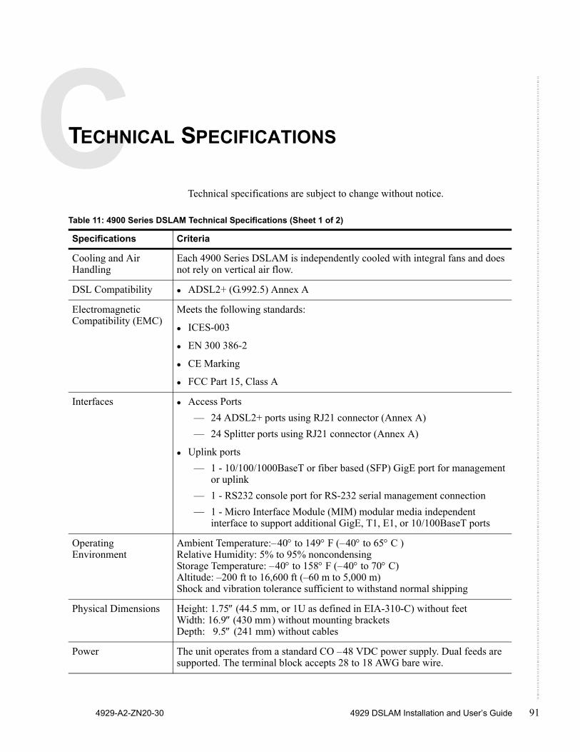
4929-A2-ZN20-30 4929 DSLAM Installation and User’s Guide 91
TECHNICAL SPECIFICATIONS
Technical specifications are subject to change without notice.
Table 11: 4900 Series DSLAM Technical Specifications (Sheet 1 of 2)
Specifications Criteria
Cooling and Air Handling
Each 4900 Series DSLAM is independently cooled with integral fans and does not rely on vertical air flow.
DSL Compatibility ADSL2+ (G.992.5) Annex A
Electromagnetic Compatibility (EMC)
Meets the following standards:
ICES-003
EN 300 386-2
CE Marking
FCC Part 15, Class A
Interfaces Access Ports— 24 ADSL2+ ports using RJ21 connector (Annex A)— 24 Splitter ports using RJ21 connector (Annex A)
Uplink ports— 1 - 10/100/1000BaseT or fiber based (SFP) GigE port for management
or uplink— 1 - RS232 console port for RS-232 serial management connection— 1 - Micro Interface Module (MIM) modular media independent
interface to support additional GigE, T1, E1, or 10/100BaseT ports
Operating Environment
Ambient Temperature:–40° to 149° F (–40° to 65° C )Relative Humidity: 5% to 95% noncondensingStorage Temperature: –40° to 158° F (–40° to 70° C)Altitude: –200 ft to 16,600 ft (–60 m to 5,000 m)Shock and vibration tolerance sufficient to withstand normal shipping
Physical Dimensions Height: 1.75″ (44.5 mm, or 1U as defined in EIA-310-C) without feetWidth: 16.9″ (430 mm) without mounting brackets Depth: 9.5″ (241 mm) without cables
Power The unit operates from a standard CO –48 VDC power supply. Dual feeds are supported. The terminal block accepts 28 to 18 AWG bare wire.
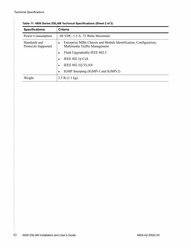
Technical Specifications
92 4929 DSLAM Installation and User’s Guide 4929-A2-ZN20-30
Power Consumption –48 VDC, 1.5 A: 72 Watts Maximum
Standards and Protocols Supported
Enterprise MIBs Chassis and Module Identification, Configuration, Multimedia Traffic Management
Flash Upgradeable IEEE 802.3
IEEE 802.1p CoS
IEEE 802.1Q VLAN
IGMP Snooping (IGMPv1 and IGMPv2)
Weight 2.5 lb (1.1 kg)
Table 11: 4900 Series DSLAM Technical Specifications (Sheet 2 of 2)
Specifications Criteria
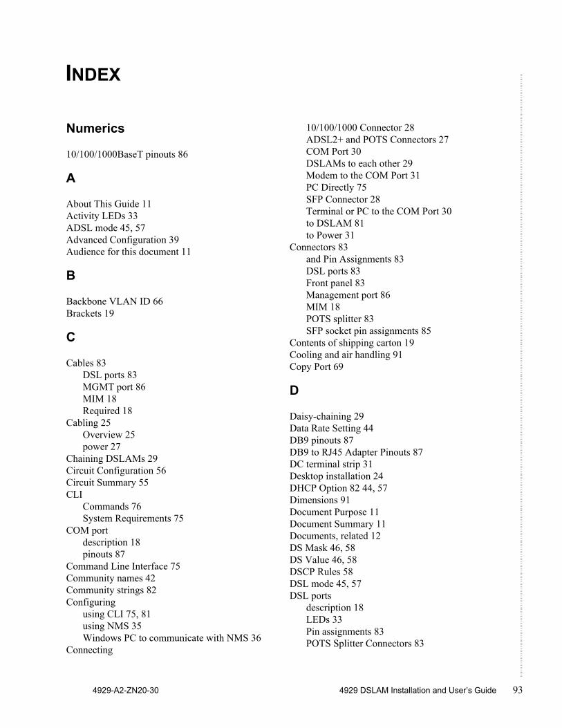
4929-A2-ZN20-30 4929 DSLAM Installation and User’s Guide 93
INDEX
Numerics
10/100/1000BaseT pinouts 86
A
About This Guide 11Activity LEDs 33ADSL mode 45, 57Advanced Configuration 39Audience for this document 11
B
Backbone VLAN ID 66Brackets 19
C
Cables 83DSL ports 83MGMT port 86MIM 18Required 18
Cabling 25Overview 25power 27
Chaining DSLAMs 29Circuit Configuration 56Circuit Summary 55CLI
Commands 76System Requirements 75
COM portdescription 18pinouts 87
Command Line Interface 75Community names 42Community strings 82Configuring
using CLI 75, 81using NMS 35Windows PC to communicate with NMS 36
Connecting
10/100/1000 Connector 28ADSL2+ and POTS Connectors 27COM Port 30DSLAMs to each other 29Modem to the COM Port 31PC Directly 75SFP Connector 28Terminal or PC to the COM Port 30to DSLAM 81to Power 31
Connectors 83and Pin Assignments 83DSL ports 83Front panel 83Management port 86MIM 18POTS splitter 83SFP socket pin assignments 85
Contents of shipping carton 19Cooling and air handling 91Copy Port 69
D
Daisy-chaining 29Data Rate Setting 44DB9 pinouts 87DB9 to RJ45 Adapter Pinouts 87DC terminal strip 31Desktop installation 24DHCP Option 82 44, 57Dimensions 91Document Purpose 11Document Summary 11Documents, related 12DS Mask 46, 58DS Value 46, 58DSCP Rules 58DSL mode 45, 57DSL ports
description 18LEDs 33Pin assignments 83POTS Splitter Connectors 83
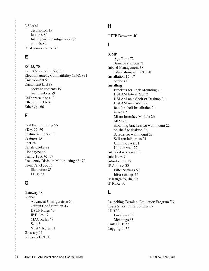
94 4929 DSLAM Installation and User’s Guide 4929-A2-ZN20-30
DSLAMdescription 15features 89Interconnect Configuration 73models 89
Dual power source 32
E
EC 55, 70Echo Cancellation 55, 70Electromagnetic Compatibility (EMC) 91Environment 91Equipment List 89
package contents 19part numbers 89
ESD precautions 19Ethernet LEDs 33Ethertype 66
F
Fast Buffer Setting 55FDM 55, 70Feature numbers 89Features 15Feet 24Ferrite choke 28Flood type 66Frame Type 45, 57Frequency Division Multiplexing 55, 70Front Panel 33, 83
illustration 83LEDs 33
G
Gateway 38Global
Advanced Configuration 54Circuit Configuration 43DSCP Rules 45IP Rules 47MAC Rules 49Set 43VLAN Rules 51
Glossary 11Glossary URL 11
H
HTTP Password 40
I
IGMPAge Time 72Summary screen 71
Inband Management 38establishing with CLI 80
Installation 15, 17options 17
InstallingBrackets for Rack Mounting 20DSLAM Into a Rack 21DSLAM on a Shelf or Desktop 24DSLAM on a Wall 22feet for shelf installation 24in rack 21Micro Interface Module 26MIM 26mounting brackets for wall mount 22on shelf or desktop 24Screws for wall mount 23Self-retaining nuts 21Unit into rack 21Unit on wall 22
Intended Audience 11Interfaces 91Introduction 15IP Address 38
Filter Settings 57filter settings 44
IP Range 39, 48, 60IP Rules 60
L
Launching Terminal Emulation Program 76Layer 2 Port Filter Settings 57LED 33
Locations 33Meanings 33
Link LEDs 33Logging In 76
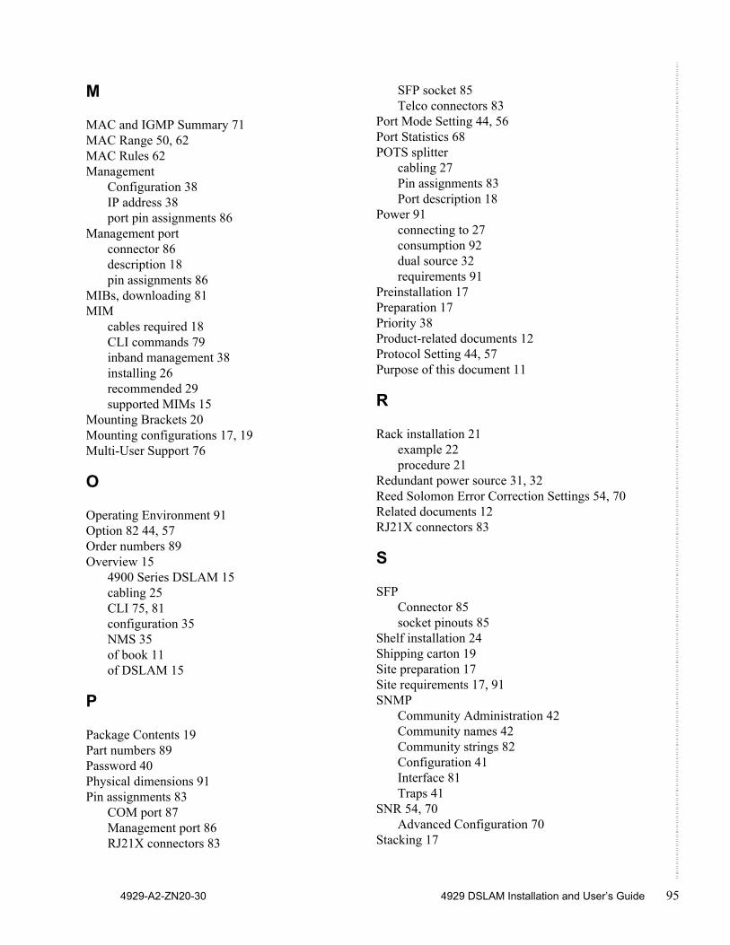
4929-A2-ZN20-30 4929 DSLAM Installation and User’s Guide 95
M
MAC and IGMP Summary 71MAC Range 50, 62MAC Rules 62Management
Configuration 38IP address 38port pin assignments 86
Management portconnector 86description 18pin assignments 86
MIBs, downloading 81MIM
cables required 18CLI commands 79inband management 38installing 26recommended 29supported MIMs 15
Mounting Brackets 20Mounting configurations 17, 19Multi-User Support 76
O
Operating Environment 91Option 82 44, 57Order numbers 89Overview 15
4900 Series DSLAM 15cabling 25CLI 75, 81configuration 35NMS 35of book 11of DSLAM 15
P
Package Contents 19Part numbers 89Password 40Physical dimensions 91Pin assignments 83
COM port 87Management port 86RJ21X connectors 83
SFP socket 85Telco connectors 83
Port Mode Setting 44, 56Port Statistics 68POTS splitter
cabling 27Pin assignments 83Port description 18
Power 91connecting to 27consumption 92dual source 32requirements 91
Preinstallation 17Preparation 17Priority 38Product-related documents 12Protocol Setting 44, 57Purpose of this document 11
R
Rack installation 21example 22procedure 21
Redundant power source 31, 32Reed Solomon Error Correction Settings 54, 70Related documents 12RJ21X connectors 83
S
SFPConnector 85socket pinouts 85
Shelf installation 24Shipping carton 19Site preparation 17Site requirements 17, 91SNMP
Community Administration 42Community names 42Community strings 82Configuration 41Interface 81Traps 41
SNR 54, 70Advanced Configuration 70
Stacking 17
96 4929 DSLAM Installation and User’s Guide 4929-A2-ZN20-30
Standards 91Subnet Mask 38Synopsis of chapters 11System
Location 39Name 39Requirements 75
T
Technical Specifications 91Telco connectors 83Telnet 39Terminal strip 31TFTP 39Trap Managers 41Traps 41Troubleshooting, LEDs 33
U
Unpacking 19Uplink ports 91
V
VLAN ID 38VLAN Rules 64VPI/VCI Detect Setting 44, 57
W
Wall mountbracket installation 22screw positions 23
Web Interface System Requirements 35Weight 91Windows 36