Embed Size (px)
Citation preview
492 IEEE TRANSACTIONS ON COMPUTER-AIDED DESIGN OF INTEGRATED CIRCUITS AND SYSTEMS, VOL. 39, NO. 2, FEBRUARY 2020
Automated Nonintrusive Analysis of ElectronicSystem Level Designs
Mehran Goli , Student Member, IEEE, Jannis Stoppe, and Rolf Drechsler, Fellow, IEEE
Abstract—Due to the ever increasing complexity of hardwaresystems, designers strive for higher levels of abstractions in theearly stages of the design process. Modeling hardware at theelectronic system level (ESL) is one way to address this demand,with the C++-based system modeling framework SystemC andits abstract communication library transaction level modeling(TLM) having become de-facto standards for ESL system design.While the C++ compiler is sufficient to compile and simu-late a given ESL design, for tasks of design understanding,debugging, or validation (where access to the details of design’sstructure and behavior is necessarily required), design needsto be processed by an appropriate tool. This problem is oftensolved by adding instrumentation code to either the design orthe library, usually resulting in incomplete logs, work over-head and/or incompatibilities. This paper introduces an approachthat automatically extracts information about both, structureand behavior of SystemC designs and TLM transactions, non-intrusively. The information is retrieved from a given designby running it in debug mode while being connected to a pre-programmed debugger, thus leaving the existing sources andworkflows untouched while collecting a vast amount of datawithout user intervention. Illustrating use cases, value changedump files of the SystemC models’ behavior and unified modelinglanguage activity diagrams of transaction protocols are createdautomatically from simulation runs.
Index Terms—Data extraction, GNU debugger (GDB), nonin-trusive, SystemC, transaction level modeling (TLM), transaction.
I. INTRODUCTION
THE EVER-INCREASING complexity of circuits and tighttime-to-market constraints make designers work on rais-
ing levels of abstraction. System design at the electronicsystem level [25] (ESL) is one way to work on more abstract
Manuscript received April 20, 2018; revised August 9, 2018 and October 19,2018; accepted November 30, 2018. Date of publication December 25, 2018;date of current version January 18, 2020. This work was supported inpart by the German Federal Ministry of Education and Research (BMBF)within the Project SecRec under Grant 16K1S0606K, in part by the GermanResearch Foundation within the Subproject P01 “Predictive function” ofthe Collaborative Research Center under Grant SFB1232, and in part bythe University of Bremen’s Graduate School SyDe through the GermanExcellence Initiative. This paper was recommended by Associate EditorS. Kim. (Corresponding author: Mehran Goli.)
M. Goli and R. Drechsler are with the Institute of Computer Science,German Research Center for Artificial Intelligence (DFKI GmbH), 28359Bremen, Germany, and also with the Department of Mathematics andComputer Science, University of Bremen, 28359 Bremen, Germany(e-mail: [email protected]).
J. Stoppe is with the Institute of Computer Science, German ResearchCenter for Artificial Intelligence (DFKI GmbH), 28359 Bremen, Germany, andalso with the Maritime Security Technologies, DLR Institute for the Protectionof Maritime Infrastructures, 27572 Bremerhaven, Germany.
Color versions of one or more of the figures in this paper are availableonline at http://ieeexplore.ieee.org.
Digital Object Identifier 10.1109/TCAD.2018.2889665
layers, allowing designers to implement executable mixedhardware-software simulations in high-level programming lan-guages. The system-level library SystemC [5] has become thede-facto standard [36] to specify HW–SW designs at the ESL.SystemC includes a framework for transaction level modeling(TLM), providing the designer with standardized interfaces tomodel communication channels that at the same time providefast simulation times. TLM focuses on functionality of datatransfers among computational components and differentiatesbetween the details of communication and the computation [7].To model the communication, TLM provides designers witha set of TLM-2.0 components which are the base protocol(which provides a common infrastructure for all use cases),the generic payload (which represents a standardized way tomodel data that should be transferred) and the communica-tion interfaces (which provide readily available methods toimplement the required protocols).
Analyzing a given SystemC design in order to know therespective components of the design (e.g., structure) as well astheir relation to each other (e.g., behavior) is a crucial as C++(and thus also SystemC, which is a library for the former) isinherently hard to analyze due to the following.
1) The lack of proper analysis methods for C++ run-time behavior (e.g., the lack of a modern reflectionframework).
2) The countless compiler-specific dialects that a sourcecode may have.
3) The executable binary format which not only is strippedof any information that is not needed to execute thesimulation but may also be heavily optimized.
These make the information retrieval from SystemC models anontrivial task.
In addition to the aforementioned obstacles to analyze anESL model, in case of SystemC TLM-2.0 designs this analysiscan be even more difficult. The complete TLM communica-tions represent a complex process that passes several phasesand may be spread out far (concerning both, time and code).A complete system model may contain a vast amount of theTLM-2.0 base protocols—so understanding them becomes acomplex (but still crucial) task whenever, e.g., new developersenter a team or are assigned new issues to work on.
While a well-written and up-to-date documentation shouldbe a primary source for these cases, there may be situa-tions where these documents have become outdated or areunavailable. For these or other situations (e.g., to validate thata given documentation still corresponds to the current state ofthe implementation), a way to generate a proper model froma given implementation would be desirable. Moreover, a partfrom the fact that knowing the properties of a given design(both structure and behavior) is necessary to understand it,this information can facilitate other steps of the design processsuch as debugging, validation, verification, and synthesis of themodel [15], [16].
0278-0070 c© 2018 IEEE. Personal use is permitted, but republication/redistribution requires IEEE permission.See http://www.ieee.org/publications_standards/publications/rights/index.html for more information.
Authorized licensed use limited to: Deutsches Zentrum fuer Luft- und Raumfahrt. Downloaded on February 22,2021 at 09:39:59 UTC from IEEE Xplore. Restrictions apply.
GOLI et al.: AUTOMATED NONINTRUSIVE ANALYSIS OF ESL DESIGNS 493
To this end, this paper introduces a new method that focuseson retrieving run-time information of ESL models and pre-senting them in a structured format. The extracted informationdescribes both structure (architecture) of designs (i.e., the mod-ules, attributes, member functions, binding information of themodules’ signals, and parameters of functions) and their simu-lation behavior (i.e., the sequence of the modules’ activations,value changes and function calls during the execution). Toillustrate how this behavioral information can be processedto facilitate design understanding, it is automatically trans-formed into value change dump (VCD) file and a set ofunified modeling language (UML) [32] models for SystemCand TLM-2.0 designs, respectively. The UML models spec-ify the behavior of transactions, allowing designers to use afamiliar, abstract design language to understand the behaviorthat is actually occurring during simulation. In order to showhow the extracted information assists the design process, thisinformation is used to validate that a given ESL design adheresto its formal specification.
In summary, the main contributions of this paper are asfollows.
1) The automatic and nonintrusive extraction of detailedinformation of a given ESL design which reflects itsstructure and behavior.
2) The presentation of the architectural information of ESLmodels in structured formats such as XML that can beused during the design process with minimal effort tobe set up by designers.
3) The presentation of the extracted run-time informationof SystemC models in form of VCDs.
4) The automatic creation of proper logs of the transac-tions of TLM-2.0 models—and their presentation as aUML diagram to enable the designer to easily trace thetransactions’ behavior.
5) The determination of the transactions’ types that areimplemented in a given TLM-2.0 design.
6) The validation of ESL designs.7) The application of the proposed method to several
ESL benchmarks in various domains to evaluate itseffectiveness.
The rest of this paper is organized as follows. Section IIoutlines existing approaches in this area and compares themto the proposed method. Section III presents the methodologyin detail. Section IV includes the use of the proposed methodto facilitate the design process, specifically validation of ESLdesign. The evaluation and experimental results are presentedin Section V. Finally, this paper is concluded in Section VI.
II. RELATED WORK
Analyzing SystemC designs (e.g., for design understand-ing) is an active field of research. Several methods have beendeveloped to satisfy this goal, each of them with its ownfeatures and issues. A common denominator for all thesemethods is whether they are based on static or hybrid tech-niques. Static approaches rely on extracting information fromthe original source code or the compiled binary model of themusing parsers [12], [17], [30], [37] or existing C++ front-ends [8], [9], [35]. They do not (by definition) analyze theexecution of the models. Their results can only describe someinformation related to the structure of a model and in thebest case can be represented in an abstract syntax tree (AST).Besides the static data extraction, hybrid approaches retrieveadditional information of a given SystemC design during itsexecution. While this is required to retrieve a model’s behavior,
it is often also the only reliable method to retrieve the struc-ture of a design as SystemC creates all its modules duringthe elaboration phase (during which the design’s modules arecreated) at run-time.
As the extraction of dynamic information is necessary todescribe both structure and behavior of a given ESL design,the hybrid methods have received the most attention lately.In this section, we thus give an overview of hybrid methodsbased on whether they support TLM or only analyze plainSystemC, illustrating their features and issues.
A. Methods That Do Not Support TLM
The analysis methods of SystemC designs that do not sup-port TLM constructs are introduced in this section. Theseapproaches extract either the model structure or dynamicbehavior of the model, or both.
In [13], the AST of a SystemC model is retrieved by parsingthe model using a PCCTS-based parser. To extract dynamicinformation an instrumented version of the original sourcecode is generated by adding some recorder function. The stateof all variables of the model is recorded by executing itselaboration phase. Using the PCCTS-based parser limits theavailable SystemC constructs as it does not fully support theentire instruction set of C++. The recorder function makesthe method an intrusive solution, modifying a design’s originalsources.
PinaVM [24] extracts the structure of a SystemC modelfrom the translated version of the source code into LLVM bit-code by executing its elaboration phase. To extract the dynamicinformation, it specifies the parts of the source code whichcontain the parameters of interest (e.g., the address of ports orevents in SystemC constructs). Afterwards, new functions areconstructed to be added to the model during its compilation.Those parameters are retrieved using the generated functionsduring the model’s execution. PinaVM takes advantage of theLLVM project to analyze SystemC models which limits it tosetups that are built using LLVM.
SHaBE [10] retrieves the static data by utilizing the GNUdebugger (GDB) [38] and extracts the dynamic informationusing a GCC plugin. In the next step, the dynamic informationis linked with the hierarchical information and stored as anintermediate representation. The method has limitations toextract some static and dynamic information of SystemC con-structs (e.g., SystemC primitive channels or processes sensitiveto certain events).
The method presented in [39] uses aspect-oriented program-ming (AOP) to extract the behavioral data. AOP is a paradigmthat allows the designer to write refactoring rules that areapplied before compiling a program (a process called weav-ing). This approach comes with several pitfalls. DebuggingAOP setups is a complex task, just like setting up a workingAOP environment. Furthermore, the current implementation ofAspectC++ which can be used in tandem with SystemC doesnot support, e.g., join points for field access (i.e., field variableassignments cannot be tracked), privileged aspects, templates,or macros, which limits the goal of arbitrary behavior tracing.
B. Methods That Support TLM
The methods that can analyze TLM models are introducedin this section. These approaches extract either the modelstructure or transaction behavior, or both.
Pinapa [27] retrieves the information of SystemC mod-els in two steps. First, the AST of the models is extractedusing a C++ front-end. Second, the elaboration phase of the
Authorized licensed use limited to: Deutsches Zentrum fuer Luft- und Raumfahrt. Downloaded on February 22,2021 at 09:39:59 UTC from IEEE Xplore. Restrictions apply.
494 IEEE TRANSACTIONS ON COMPUTER-AIDED DESIGN OF INTEGRATED CIRCUITS AND SYSTEMS, VOL. 39, NO. 2, FEBRUARY 2020
models is executed to extract their dynamic information. Theextracted information is linked to the AST to create the finalresult. However, the method describes the structure of a givenSystemC model, it does not provide any information to reflectthe design’s behavior such as the order of function calls andprocess activation.
The SystemC verification (SCV) library by the open sys-temC initiative (OSCI) provides designers with a set of APIs torecord transactions into a database. The APIs are divided intothree different transaction collection classes that can be instan-tiated during the execution of a SystemC TLM-2.0 model. Theresults obtained by this method can be analyzed by some com-mercial tools such as Cadence Incisive [2] or Novas Verdi [4]with modifications to the result-file format. SCV introducessome overhead in execution time. The method is an intrusivesolution to extract the behavior of a SystemC TLM-2.0 modelas the original source code needs to be manipulated. For acomplex design, this manual process is a nontrivial task.
DUST [23] is a SystemC TLM-2.0 analysis framework thatextracts both structural and behavioral information of a TLM-2.0 model. It retrieves the model’s hierarchy at the end ofthe execution of its elaboration phase and presents it in anXML format. It describes the behavior of the model by record-ing transactions at run-time. DUST works by enhancing someSystemC objects (e.g., sc_port to sc_dust_port) and using SCVconstructs which are added to the original source code. Dueto this intrusive solution, its application may thus be limitedif the SystemC library is updated but the given frameworkis not. Additionally, existing sources need to be updated touse DUST’s types instead of the standard SystemC types—asolution that may require considerable work.
The method presented in [40] takes advantage of debugsymbols to extract static information and SystemC API callsto retrieve dynamic data during the execution of a SystemCmodel. The dynamic information extracted by this method onlyreflects the structure of the model. The simulation behavior isnot captured at all though, leaving designers with static modeldescriptions. Moreover, the method only supports the debugsymbols that are generated by Microsoft VC++ and not GCCor Clang-LLVM.
Recently, an automated approach was introduced to auto-matically retrieve the structure and behavior of a given ESLmodel [34]. It uses the ROSE compiler to generate an ASTmodel of the design which is then used to generate anintermediate representation (IR). The IR is analyzed to extractboth architectural information of the model and behavior asgraphical multithread communication charts. However, solelyrelying on a static analysis, the method shares the limitationsof previous static approaches. It cannot consider parameterswhich are set at run-time (and may affect the design’s behav-ior). The behavioral information is restricted to only describehigh level interaction of modules—thus, behavior such asvalue changes of a module’s ports and function’s variablesduring execution are not traceable. Moreover, the method doesnot support designs including pointers or array indices in portmappings.
In summary, existing solutions have two major limitations interms of precise behavior extraction of a given ESL model andcustom code annotations or language constructs. The first limi-tation is that most of them extract a limited set of informationthat only describes the structure of the model and does notreflect its run-time behavior. The second limitation is thatmost of them can only be applied to a restricted range ofSystemC designs and do not support TLM constructs. Thoseapproaches that analyze the SystemC TLM-2.0 models mostly
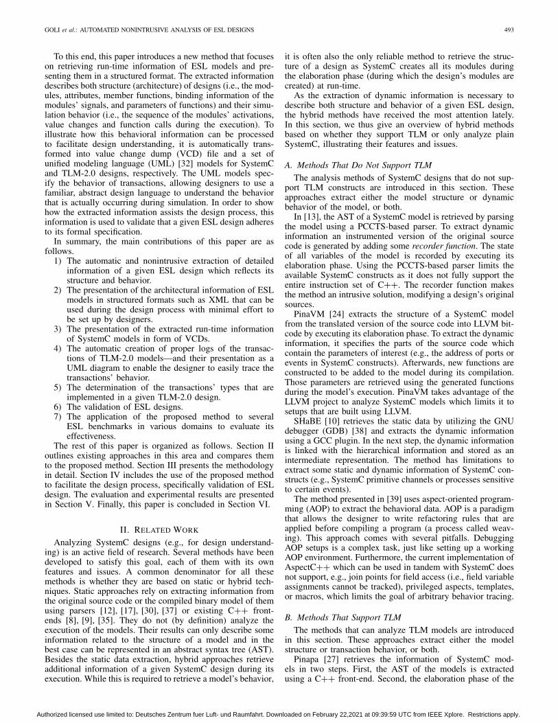
Fig. 1. Architecture of the proposed method.
rely on manipulating the original source code (which is eitherexpensive for manual processes or may have compatibilityproblems for automated approaches) or the SystemC libraryand interfaces (which may be an issue for the application ofseveral approaches in parallel, future updates, or restrictiveenvironments).
III. METHODOLOGY
As illustrated in Fig. 1, the core idea of the proposed methodto specify a given ESL design in terms of its structure andsimulation behavior consists of three steps.
1) The static information of the compiled model is retrievedby analyzing its debug symbols to satisfy two goals.
a) Identifying all components and their attributes andmember functions which are required to describestructure of the model (e.g., the name and type ofthe modules’ variables).
b) Automatically generating a set of GDB instruc-tions tailored to be used in the next step to extractthe model’s structure (dynamic data) and trace itsbehavior.
2) The model is executed via GDB using the previouslygenerated instructions. The model’s structure is retrievedwhen the execution reaches the objects for which thecorresponding instructions to extract their informationwere generated. The execution of the model is pausedat certain events (such as function calls) to record therun-time information.
3) The extracted information is automatically transformedinto structured formats that can be used during thedesign process with minimal effort to setup by design-ers. The architecture of ESL models is presented in XMLformat, while the behavior of them as a VCD file.
Although this idea (executing a given ESL program in debugmode to access its run-time behavior using a preprogrammeddebugger) properly works for analyzing SystemC designs [14],to support TLM constructs it requires some enhancements.
As stated in [11] and [23] to properly understand a givenTLM model, its structure and its transactions’ behavior needto be recorded and analyzed. The former refers to the objectinstances that are created and describe the structure of a TLMdesign (such as modules, functions and signals). The latterrefers to the run-time information which specifies the flowof modules’ communication with respect to transaction’s dataincluding transaction creation and manipulation.
The main difficulty to be overcome here is to nonintru-sively trace each TLM transaction’s payload at run-time. Todeal with this issue, we take advantage of the TLM-2.0
Authorized licensed use limited to: Deutsches Zentrum fuer Luft- und Raumfahrt. Downloaded on February 22,2021 at 09:39:59 UTC from IEEE Xplore. Restrictions apply.
GOLI et al.: AUTOMATED NONINTRUSIVE ANALYSIS OF ESL DESIGNS 495
rule stated in [7]—a transaction object is passed as a func-tion argument to a method implementing one of the givencommunication-interfaces (b-transport or nb-transport) with areference address (call by reference). The reference address ofa transaction object remains constant from its creation until itsdestruction (i.e., during its lifetime). For transactions that aregenerated by different TLM initiator modules, the referenceaddress of transactions can thus be used to isolate informationrelated to each of them. This reference address is used asa transaction ID which is the main key to trace a transac-tion (related information to build its lifetime) among othertransactions within the simulation log of a TLM design.
Therefore, in order to make the debugger properly trace andlog the TLM payloads and function calls, the instructions mustbe generated specifically with regard to this case in step one,thus altering the execution in step two to extract the desiredinformation about TLM transactions.
The enhancements that need to be performed in each stepto extract and present the required TLM information are asfollows.
1) Extract the structure from the TLM model to recog-nize the transaction object and its related parameters(e.g., phase, delay) for each TLM module.
2) Record the transaction’s flow (i.e., the information ofcaller and callee object that communicate) and thetransaction’s data (i.e., the transaction’s attribute).
3) Reflect the behavioral information in a big scale viewto empower the designer to easily trace transactions’behavior. The extracted information is translated to a setof UML models once the execution finishes. Using anUML model to reflect the behavioral information enablesdesigners to easily trace both transaction flow and dataat the same time.
A. Static Information Retrieval
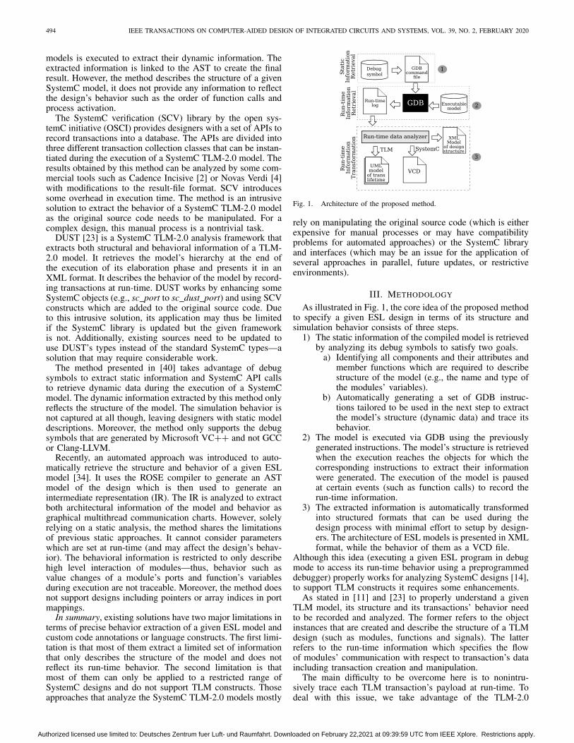
The model’s static information is retrieved by analyzingits debug symbols (which is generated by the GDB) toextract all SystemC (e.g., name of modules and their mem-ber functions and attributes) and TLM constructs (e.g., thegeneric payload data type, initiator and target sockets, andthe TLM utilities). This information is required to reflectthe model’s structure and trace its transactions (in case ofSystemC TLM-2.0 designs) at run-time. For instance, considerthe AT-example (which is explained in detail in Section V-A).A part of the static information related to the design’s struc-ture is presented in its generated debug symbols (Fig. 2,lines 8–15). It shows that the design contains a moduleAT-typeA-initiator with (among others) an initiatorsocket socket and a member function nb_transport_bwwith return type tlm_sync_enum.
The retrieved information is translated into a more man-ageable data format in which each module is described ina hierarchical structure based on its member functions andattributes. Unlike other static approaches that consider thistype of information as the result, this information is usedas the foundation to extract additional run-time information.A GDB command file (GCF) which is used to programGDB is automatically generated based on this static data.It controls the execution of the ESL executable model run-ning on GDB to extract the desired information in thesimulation run.
For example, to extract all transactions related to theAT-example’s initiator module AT-typeA-initiator, weneed to trace all functions of the module in which a transaction
Fig. 2. Part of the debug symbol of the AT-example design generated by GDB.
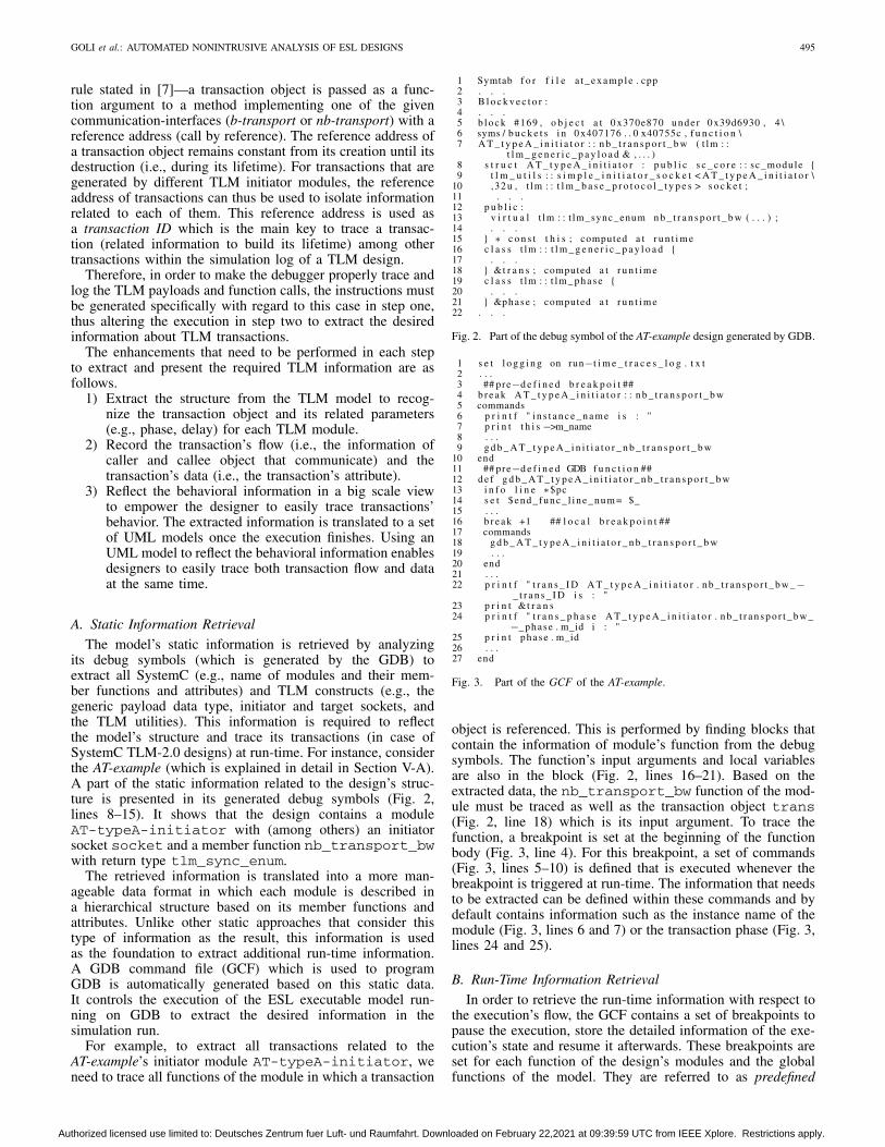
Fig. 3. Part of the GCF of the AT-example.
object is referenced. This is performed by finding blocks thatcontain the information of module’s function from the debugsymbols. The function’s input arguments and local variablesare also in the block (Fig. 2, lines 16–21). Based on theextracted data, the nb_transport_bw function of the mod-ule must be traced as well as the transaction object trans(Fig. 2, line 18) which is its input argument. To trace thefunction, a breakpoint is set at the beginning of the functionbody (Fig. 3, line 4). For this breakpoint, a set of commands(Fig. 3, lines 5–10) is defined that is executed whenever thebreakpoint is triggered at run-time. The information that needsto be extracted can be defined within these commands and bydefault contains information such as the instance name of themodule (Fig. 3, lines 6 and 7) or the transaction phase (Fig. 3,lines 24 and 25).
B. Run-Time Information Retrieval
In order to retrieve the run-time information with respect tothe execution’s flow, the GCF contains a set of breakpoints topause the execution, store the detailed information of the exe-cution’s state and resume it afterwards. These breakpoints areset for each function of the design’s modules and the globalfunctions of the model. They are referred to as predefined
Authorized licensed use limited to: Deutsches Zentrum fuer Luft- und Raumfahrt. Downloaded on February 22,2021 at 09:39:59 UTC from IEEE Xplore. Restrictions apply.
496 IEEE TRANSACTIONS ON COMPUTER-AIDED DESIGN OF INTEGRATED CIRCUITS AND SYSTEMS, VOL. 39, NO. 2, FEBRUARY 2020
Fig. 4. Part of the structural presentation of the architecture of the AT-example.
breakpoints (line 4 in Fig. 3) as they are statically definedbased on a function’s name before running the GDB script.The predefined breakpoints (which are set up before execu-tion) are placed at any relevant function’s first line and thustriggered when their corresponding functions are called. Dueto limitations concerning the amount of breakpoints, succes-sive lines within these functions cannot all be prepared withbreakpoints before the execution as well. Instead, to recordany changes within a function, setting a new breakpoint forthe next instruction of the function is part of the set of com-mands that are executed for the first breakpoint, just like itis part of this newly set breakpoint. This recursive process isperformed repeatedly until the execution reaches the end ofthe function’s body. The goal of a predefined breakpoint is tohalt the execution at beginning of a module’s function whilesuccessive local breakpoints are used to step through the bodyof module’s function line by line.
C. Information Transformation
1) Architecture Presentation: The structure of a given ESLdesign is extracted in two steps.
1) During the static analysis in the first phase of theproposed method including:
a) the root name and type of each module;b) the name and type of each function;c) the variables of each module;d) local variables of each function.
2) During the execution of the model where each predefinedbreakpoint contains instructions for GDB to retrieve thestructural information that cannot be retrieved during thefirst phase including:
a) the instance name of each module;b) binding information of signals and sockets.
The extracted information from both steps is bound togetherto create a complete structure of the design.
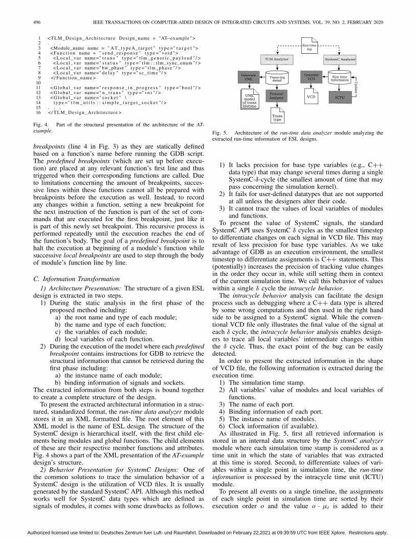
To present the extracted architectural information in a struc-tured, standardized format, the run-time data analyzer modulestores it in an XML formatted file. The root element of thisXML model is the name of ESL design. The structure of theSystemC design is hierarchical itself, with the first child ele-ments being modules and global functions. The child elementsof these are their respective member functions and attributes.Fig. 4 shows a part of the XML presentation of the AT-exampledesign’s structure.
2) Behavior Presentation for SystemC Designs: One ofthe common solutions to trace the simulation behavior of aSystemC design is the utilization of VCD files. It is usuallygenerated by the standard SystemC API. Although this methodworks well for SystemC data types which are defined assignals of modules, it comes with some drawbacks as follows.
Fig. 5. Architecture of the run-time data analyzer module analyzing theextracted run-time information of ESL designs.
1) It lacks precision for base type variables (e.g., C++data type) that may change several times during a singleSystemC-δ-cycle (the smallest amount of time that maypass concerning the simulation kernel).
2) It fails for user-defined datatypes that are not supportedat all unless the designers alter their code.
3) It cannot trace the values of local variables of modulesand functions.
To present the value of SystemC signals, the standardSystemC API uses SystemC δ cycles as the smallest timestepto differentiate changes on each signal in VCD file. This mayresult of less precision for base type variables. As we takeadvantage of GDB as an execution environment, the smallesttimestep to differentiate assignments is C++ statements. This(potentially) increases the precision of tracking value changesin the order they occur in, while still setting them in contextof the current simulation time. We call this behavior of valueswithin a single δ cycle the intracycle behavior.
The intracycle behavior analysis can facilitate the designprocess such as debugging where a C++ data type is alteredby some wrong computations and then used in the right handside to be assigned to a SystemC signal. While the conven-tional VCD file only illustrates the final value of the signal ateach δ cycle, the intracycle behavior analysis enables design-ers to trace all local variables’ intermediate changes withinthe δ cycle. Thus, the exact point of the bug can be easilydetected.
In order to present the extracted information in the shapeof VCD file, the following information is extracted during theexecution time.
1) The simulation time stamp.2) All variables’ value of modules and local variables of
functions.3) The name of each port.4) Binding information of each port.5) The instance name of modules.6) Clock information (if available).As illustrated in Fig. 5, first all retrieved information is
stored in an internal data structure by the SystemC analyzermodule where each simulation time stamp is considered as atime unit in which the state of variables that was extractedat this time is stored. Second, to differentiate values of vari-ables within a single point in simulation time, the run-timeinformation is processed by the intracycle time unit (ICTU)module.
To present all events on a single timeline, the assignmentsof each single point in simulation time are sorted by theirexecution order o and the value o · μt is added to their
Authorized licensed use limited to: Deutsches Zentrum fuer Luft- und Raumfahrt. Downloaded on February 22,2021 at 09:39:59 UTC from IEEE Xplore. Restrictions apply.
GOLI et al.: AUTOMATED NONINTRUSIVE ANALYSIS OF ESL DESIGNS 497
Algorithm 1: ICTU Update ProcessInput: simulation time scale stc, Run-time Information RIOutput: updated RIforeach time unit t in RI do
foreach variable v in t dovc[t][v]← sum(uinq value changes v);
endtvc[t]← sum(vc[t]);
endmaxtvc ← max(tvc);μt ← (1/maxtvc) ∗stc;foreach time unit t in RI do
foreach variable v in t doif vc[t][v] > 1 then
foreach value assignment dotnew ← t + μt;store (tnew, value assignment);t← tnew;
endend
endendupdate (RI);
original timestamps. The value μt is thus used to differen-tiate the particular assignments. It should be much smallerthan the smallest step in simulation time in order to have allassignments being displayed before the next “large” simula-tion timestep. μt is therefore related to the maximum sum ofthe number of value changes of variables in a time unit amongall time units as illustrated in Algorithm 1 and is calculatedautomatically.
Finally, the updated version of the run-time information isused to generate a VCD file of the design’s behavior via thegenerate VCD module.
3) Behavior Presentation for TLM Designs: To present thebehavior of a given SystemC TLM-2.0 model, both transactionflow and transaction data are retrieved and stored in the run-time log file. To extract the transaction flow, each predefinedGDB function contains instructions for GDB to extract thefollowing.
1) The sequence number of objects’ activation.2) The root name of each module taking part in the
transaction.3) The role of each module taking part in the transaction
(for TLM modules can be initiator, interconnect or targetand for others is global).
4) The instance name of each module.5) The name of the current function, its arguments’ values
and its return value (if available).6) Source code information (i.e., line of code and source
file name).7) The simulation time.8) The transaction reference address.In order to retrieve the transaction data, the GDB instruc-
tions extract the attributes of a transaction object which arethe following.
1) Data value.2) Address.3) Command.4) Data length.5) Response status.In the next step, the extracted information in the run-time
log file is translated to a structured format. To do this, theinformation related to each single transaction within its life-time is distinguished from other transactions. In order to trace
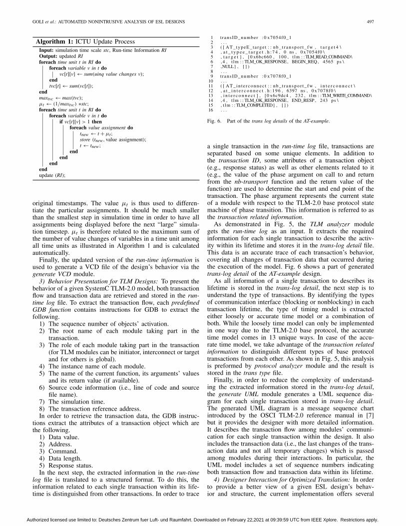
Fig. 6. Part of the trans log details of the AT-example.
a single transaction in the run-time log file, transactions areseparated based on some unique elements. In addition tothe transaction ID, some attributes of a transaction object(e.g., response status) as well as other elements related to it(e.g., the value of the phase argument on call to and returnfrom the nb-transport function and the return value of thefunction) are used to determine the start and end point of thetransaction. The phase argument represents the current stateof a module with respect to the TLM-2.0 base protocol statemachine of phase transition. This information is referred to asthe transaction related information.
As demonstrated in Fig. 5, the TLM analyzer modulegets the run-time log as an input. It extracts the requiredinformation for each single transaction to describe the activ-ity within its lifetime and stores it in the trans-log detail file.This data is an accurate trace of each transaction’s behavior,covering all changes of transaction data that occurred duringthe execution of the model. Fig. 6 shows a part of generatedtrans-log detail of the AT-example design.
As all information of a single transaction to describes itslifetime is stored in the trans-log detail, the next step is tounderstand the type of transactions. By identifying the typesof communication interface (blocking or nonblocking) in eachtransaction lifetime, the type of timing model is extractedeither loosely or accurate time model or a combination ofboth. While the loosely time model can only be implementedin one way due to the TLM-2.0 base protocol, the accuratetime model comes in 13 unique ways. In case of the accu-rate time model, we take advantage of the transaction relatedinformation to distinguish different types of base protocoltransactions from each other. As shown in Fig. 5, this analysisis preformed by protocol analyzer module and the result isstored in the trans type file.
Finally, in order to reduce the complexity of understand-ing the extracted information stored in the trans-log detail,the generate UML module generates a UML sequence dia-gram for each single transaction stored in trans-log detail.The generated UML diagram is a message sequence chartintroduced by the OSCI TLM-2.0 reference manual in [7]but it provides the designer with more detailed information.It describes the transaction flow among modules’ communi-cation for each single transaction within the design. It alsoincludes the transaction data (i.e., the last changes of the trans-action data and not all temporary changes) which is passedamong modules during their interactions. In particular, theUML model includes a set of sequence numbers indicatingboth transaction flow and transaction data within its lifetime.
4) Designer Interaction for Optimized Translation: In orderto provide a better view of a given ESL design’s behav-ior and structure, the current implementation offers several
Authorized licensed use limited to: Deutsches Zentrum fuer Luft- und Raumfahrt. Downloaded on February 22,2021 at 09:39:59 UTC from IEEE Xplore. Restrictions apply.
498 IEEE TRANSACTIONS ON COMPUTER-AIDED DESIGN OF INTEGRATED CIRCUITS AND SYSTEMS, VOL. 39, NO. 2, FEBRUARY 2020
configuration options available for designers. The extractedinformation of the design can be filtered based on the follow-ing parameters.
1) Kinds of Variables: The generated VCD file is optimizedto only show the signals of modules, local variables ofmodules’ functions or variables of global functions.
2) Depth of Information: The generated VCD file mayexclude the intracycle behavior (resulting in a more“classic” SystemC trace that only tracks values whenthe simulation time advances).
3) Time Window: The generated VCD shows only theinformation from a specific period of simulation time.
4) Depth of Hierarchy: The generated XML model is opti-mized to only show the information of modules (andalso their member functions and their variables).
In case of SystemC TLM-2.0 designs, the generated UMLmodel may only show the sequence of certain modules’ activ-ity or include the transactions’ data as well. This allows thedesigner to easily focus on the points of interest in the designby filtering out any irrelevant information. Moreover, reducingthe amount of translated information enhances the readabilityof generated UML, VCD, or XML models.
IV. APPLICATION: VALIDATION OF ESL DESIGNS
In this section, the utility value of the run-time informationanalysis method is illustrated. The extracted information isused to assist the validation of an ESL design against its for-mal specification [15]. First, the importance of ESL designvalidation and the related work in this domain are presentedin Section IV-A. Second, the proposed methodology is shownin Section IV-B.
A. Background
One solution to ensure that design constraints such as timingand phases are satisfied at ESL, is the utilization of for-mal specification languages such as the UML [32] early inthe design process. UML has become a de-facto standardfor the modeling phase in design processes as it supportsobject-oriented and concurrency features that are used bySystemC [28], [31]. This enables designers to define the struc-ture and the behavior of the design in order to either createa reference model for ESL implementation or generate ESLcode stubs or initial implementation. However, manual refine-ment steps of the generated ESL model are required. As theimplementation of ESL designs based on a formal specificationis either a partly (in case of generating the initial steps auto-matically from UML model) or fully manual process, errorsmay be introduced–resulting in the final ESL model poten-tially differing from the formal reference model. Therefore,the validation of ESL design against its formal specificationis necessary.
Previous approaches (either formal or simulation-based)mostly focus on verifying SystemC TLM-2.0 designsagainst TLM-2.0 rules and do not support compliancechecking of ESL models against their formal specifica-tion [18]–[20], [22], [26]. The method [41] employs SystemCdata extraction approach [40] to extract the information ofa SystemC model. It checks the equivalence of the retrieveddata to the model’s formal specification. Due to use of [40], itinherits the same limitations which are no support for behaviorvalidation and TLM construct.
Overall, the existing methods have two major problems: incase of formal verification, methods are limited to support a
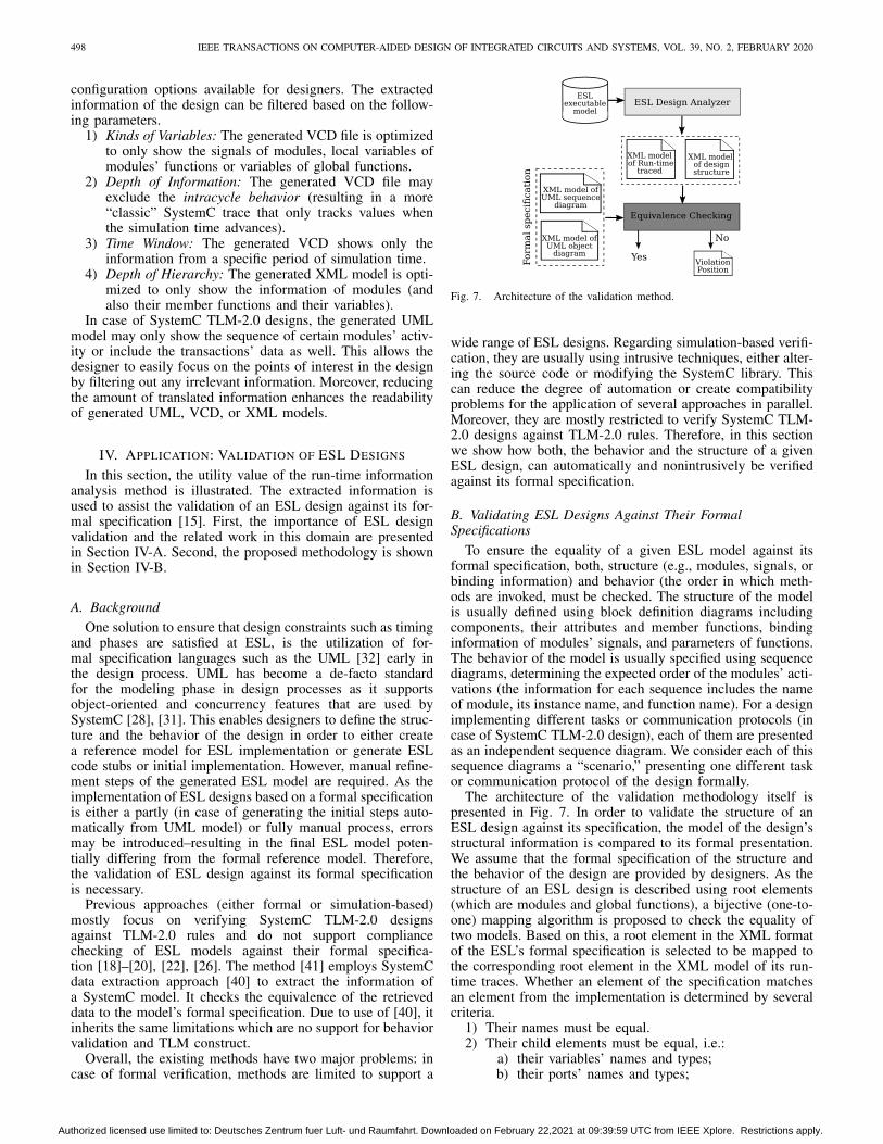
Fig. 7. Architecture of the validation method.
wide range of ESL designs. Regarding simulation-based verifi-cation, they are usually using intrusive techniques, either alter-ing the source code or modifying the SystemC library. Thiscan reduce the degree of automation or create compatibilityproblems for the application of several approaches in parallel.Moreover, they are mostly restricted to verify SystemC TLM-2.0 designs against TLM-2.0 rules. Therefore, in this sectionwe show how both, the behavior and the structure of a givenESL design, can automatically and nonintrusively be verifiedagainst its formal specification.
B. Validating ESL Designs Against Their FormalSpecifications
To ensure the equality of a given ESL model against itsformal specification, both, structure (e.g., modules, signals, orbinding information) and behavior (the order in which meth-ods are invoked, must be checked. The structure of the modelis usually defined using block definition diagrams includingcomponents, their attributes and member functions, bindinginformation of modules’ signals, and parameters of functions.The behavior of the model is usually specified using sequencediagrams, determining the expected order of the modules’ acti-vations (the information for each sequence includes the nameof module, its instance name, and function name). For a designimplementing different tasks or communication protocols (incase of SystemC TLM-2.0 design), each of them are presentedas an independent sequence diagram. We consider each of thissequence diagrams a “scenario,” presenting one different taskor communication protocol of the design formally.
The architecture of the validation methodology itself ispresented in Fig. 7. In order to validate the structure of anESL design against its specification, the model of the design’sstructural information is compared to its formal presentation.We assume that the formal specification of the structure andthe behavior of the design are provided by designers. As thestructure of an ESL design is described using root elements(which are modules and global functions), a bijective (one-to-one) mapping algorithm is proposed to check the equality oftwo models. Based on this, a root element in the XML formatof the ESL’s formal specification is selected to be mapped tothe corresponding root element in the XML model of its run-time traces. Whether an element of the specification matchesan element from the implementation is determined by severalcriteria.
1) Their names must be equal.2) Their child elements must be equal, i.e.:
a) their variables’ names and types;b) their ports’ names and types;
Authorized licensed use limited to: Deutsches Zentrum fuer Luft- und Raumfahrt. Downloaded on February 22,2021 at 09:39:59 UTC from IEEE Xplore. Restrictions apply.
GOLI et al.: AUTOMATED NONINTRUSIVE ANALYSIS OF ESL DESIGNS 499
c) their functions’ signatures (name, return type, andparameters);
d) their local variables.If no fitting root element is found in the XML model ofrun-time traces, the corresponding implementation element isreported as a violation. Otherwise, the algorithm continueswith the next element. If a specification does not includedetailed information (such as variable names or their types)this information can be easily filtered from the results in orderto keep the extracted models on roughly the same level ofabstraction as the given specification.
In order to check the compliance of a models’ behavior,the extracted run-time information from the analysis step inFig. 1 is translated to an XML model. We assume that eachdesign is run using a testbench that includes a set of testswhich provide a full coverage on the complete functionalityand all communication protocols of the design. The ESLmodel’s behavior compliance is tested by checking whethereach transaction (implementing a unique communication pro-tocol) or functionality (in case of SystemC design) matches theexpected sequences of components’ activation (i.e., functioncalls and corresponding responses).
In case of SystemC designs, in [15] the simulation run isused to generate only one sequence diagram from the run-time log. As the behavior of a design is rarely ever definedusing only one single sequence diagram, comparing this tothe given specification is difficult. Instead, each functionalityis translated into its own sequence diagram. Functionalitiesare distinguished based on test cases, for each of which aunique sequence diagram is generated. Since several test casescan activate the same functionality, we only verified uniquefunctionality to reduce the validation time. The instance nameand the name of its function are concatenated for all modulestaking part in each functionality to create a unique identifier,which is called the functionality signature. The validation algo-rithm then checks for each unique functionality in the XMLpresentation of the extracted run-time traces of the modelwhether or not it complies with the expected scenario.
Regarding SystemC TLM-2.0 designs, the algorithm checksthe equivalence of each unique transaction with the expectedscenario. Thus the first task is to create a list of unique trans-actions, each of them representing a unique communicationprotocol. This reduces the validation complexity as the designmight contain several transaction of the same communica-tion protocol. In [15] only the transactions’ reference address(transaction ID) is used as key to filter redundant transactions.This may not be sufficient as an initiator module can gen-erate two transactions with the same address implementingdifferent communication protocols (e.g., the transactions aresent to two different target modules through an interconnect).Therefore, some scenarios might not verified in this case. Tosolve this problem, in addition to the transaction ID, we addanother key to distinguish transactions that share the sameaddress: the instance name of each module taking part in trans-action lifetime is concatenated to the transaction ID to createa transaction signature.
As illustrated in Algorithm 2, a list of unique transactionsand functionalities is stored, allowing a matching scenario tobe selected from the formal specification part if available. Ifa fitting scenario is found, the success is indicated to theuser and, for each extracted transaction or functionality, acorresponding (XML formatted) log is generated from thetransaction’s run-time traces. Otherwise, while the algorithmcontinues for all transactions and scenarios, the scenarios thatcould not be matched are reported as violations.
Algorithm 2: Behavior Validation AlgorithmInput: SystemC_trace ST , TLM_trace TT , scenario_list SLOutput: Equivalence_list ELfunctionality_unique_list ful← ∅;transaction_unique_list tul← ∅;foreach functionality f in ST do
fs← functionality_signature(f );if fs not in ful then
add (fs, ful);
foreach transaction t in TLM-2.0_trace dots← trans_signature(t);if ts not in tul then
add (ts, tul);
foreach transaction/functionality t/f in ful/tul doforeach scenario s in SL do
if s in ful/tul thenEL[s]← true;
elseEL[s]← false;
V. EXPERIMENTAL EVALUATION
Several standard ESL designs from various domains havebeen used to evaluate the quality of the proposed method.The experimental evaluation is presented in two steps. First,two case studies—RISC-CPU (implemented in SystemC) [21]and AT-example (implemented in SystemC TLM-2.0) [6]—arediscussed in Section V-A. Second, we give a brief discussionbased on the obtained results to evaluate the quality of theproposed method in Section V-B. All algorithms are imple-mented in python. The experiments are carried out on a PCequipped with 8-GB RAM and an Intel core i7 CPU runningat 2.4 GHz.
A. Case Studies
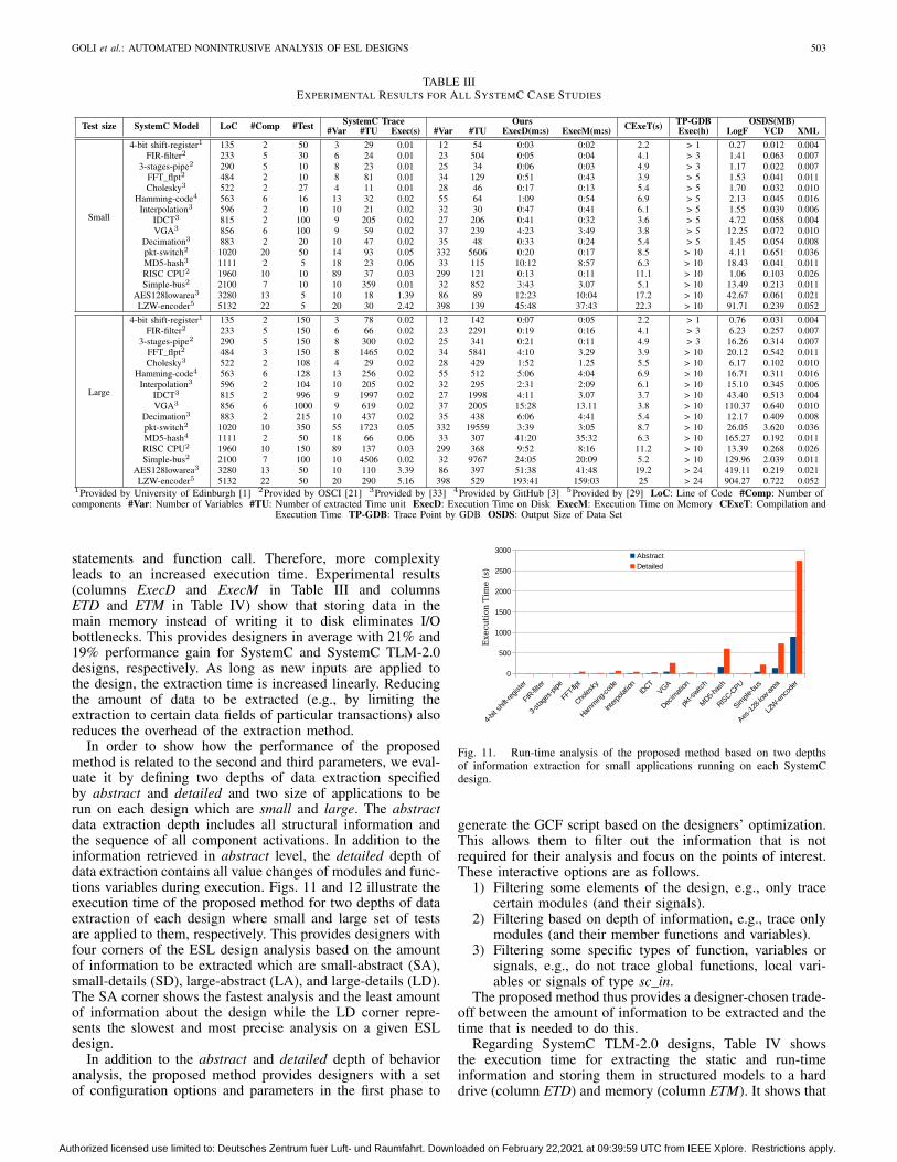
The experimental results of applying the proposed methodto all benchmarks are presented in Tables III and IV forSystemC and SystemC TLM-2.0, respectively.
The SystemC models that are presented in Table IIIare taken from the standard examples which provided byOSCI [21], S2CBench [33], GitHub [3], [29], and theUniversity of Edinburgh [1]. In this table, column test sizeillustrates the size of application running on each design.columns SystemC Model, LoC, Comp, and Test show the nameof designs, the lines of code, number of modules and the num-ber of test applying to each design, respectively. We comparethe results of our methods to the SystemC trace file API interms of the number of retrieved variables #Var, number ofextracted time units #TU and execution time Exec. ColumnsExecD and ExecM show the execution time of the proposedmethod when data is stored on disk and memory, respec-tively. As demonstrated in this table, the amount of both,retrieved variables and time units for all case studies of theproposed method are much higher than those retrieved viathe SystemC trace API. The parameter #TU represents valuechanges of variables. These parameters illustrate the accu-racy of our approach to extract the detailed behavior of aSystemC design. This difference in the amount of retrieveddata reflects one major advantage of the proposed method. Asit is able to trace value changes even for both, global and localnative variables (that have the SystemC primitive data types)or compound data types (which can be constructed using theprogramming language’s primitive data types) regardless of
Authorized licensed use limited to: Deutsches Zentrum fuer Luft- und Raumfahrt. Downloaded on February 22,2021 at 09:39:59 UTC from IEEE Xplore. Restrictions apply.
500 IEEE TRANSACTIONS ON COMPUTER-AIDED DESIGN OF INTEGRATED CIRCUITS AND SYSTEMS, VOL. 39, NO. 2, FEBRUARY 2020
whether they are placed on the stack or the heap not only whenthe simulation time advances but also of any assignments in-between. Moreover, using the SystemC trace API to analyzethe behavior of a given SystemC model is an intrusive solu-tion. It required further programming effort by the designer tomodify the original source code to include all variables thatneed to be traced. Thus, for a complex design with lots ofvariables, may be a time consuming task.
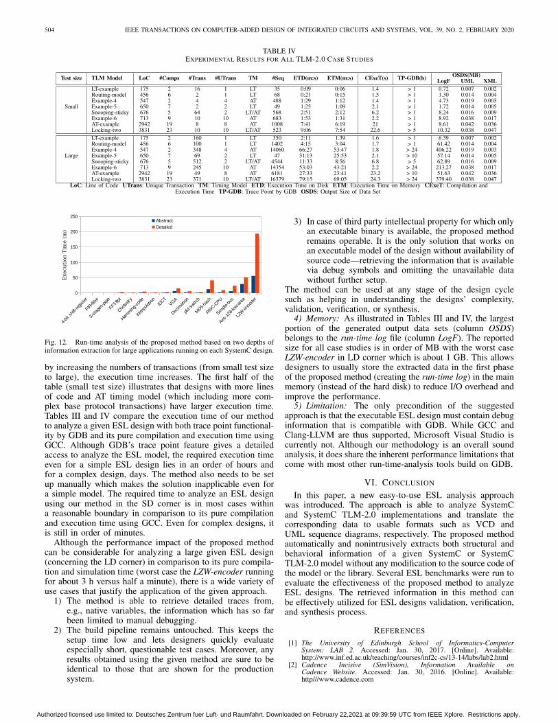
The SystemC TLM-2.0 models in Table IV are the stan-dard examples providing by Doulos [6]. Columns TLM modelshows the name of SystemC TLM-2.0 designs. The LoC and#Comp, #TM, and #Trans illustrate the complexity and dif-ference of each design in terms of lines of code, numberof components, number of transaction and the timing model,respectively. Columns #UTrans presents how many differentbase protocol transactions are implemented in each designwhich is performed automatically by analyzing each transac-tion lifetime. The #Seq column shows the number of linesrelated to the unique behavioral information that has beenextracted during the execution of each design. Column CExeTpresents the compilation and execution time of each designwithout any modification. The TP-GDB column shows foreach SystemC TLM-2.0 design the required time to analyzeit using GDB trace point. The term “GDB trace point” refersto the watchpoints feature of GDB that can be used to tracean expression such as the value of a variable or an operationduring the execution of a program. Whenever the value ofaforementioned expression changes, the corresponding watch-point automatically stops the execution and reports its oldand new values. This requires that the designer first sets abreakpoint at a specific location (e.g., a function of a design)and then adds a watchpoint to trace the desired expressions(e.g., variables or signals).
In both tables the OSDS column shows the size of gen-erated output data sets followed by size of the run-time log(column LogF) and generated XML model of each design’sstructure (column XML). Column VCD in Table III presentssize of generated VCD for each SystemC design. The UMLsize reported in Table IV is the average size of the generatedUML diagram over all transactions of each TLM design. Inboth tables, the largest output file is the run-time log (whichis generated in the first phase of the proposed method) as itincludes the detailed data and the complete history of the exe-cution. A large part of the information in the run-time log isused to track the useful data related to the behavior and struc-ture of the design and thus filtered out during the translationprocess (in the second phase). The XML and UML files forall case studies remain in the order of KB. Using the filteroptions can reduce the size of output data sets (VCD, UML,and XML) even more, allowing the designer to have a bet-ter readability, focusing the resulting logs at whatever issue iscurrently at hand.
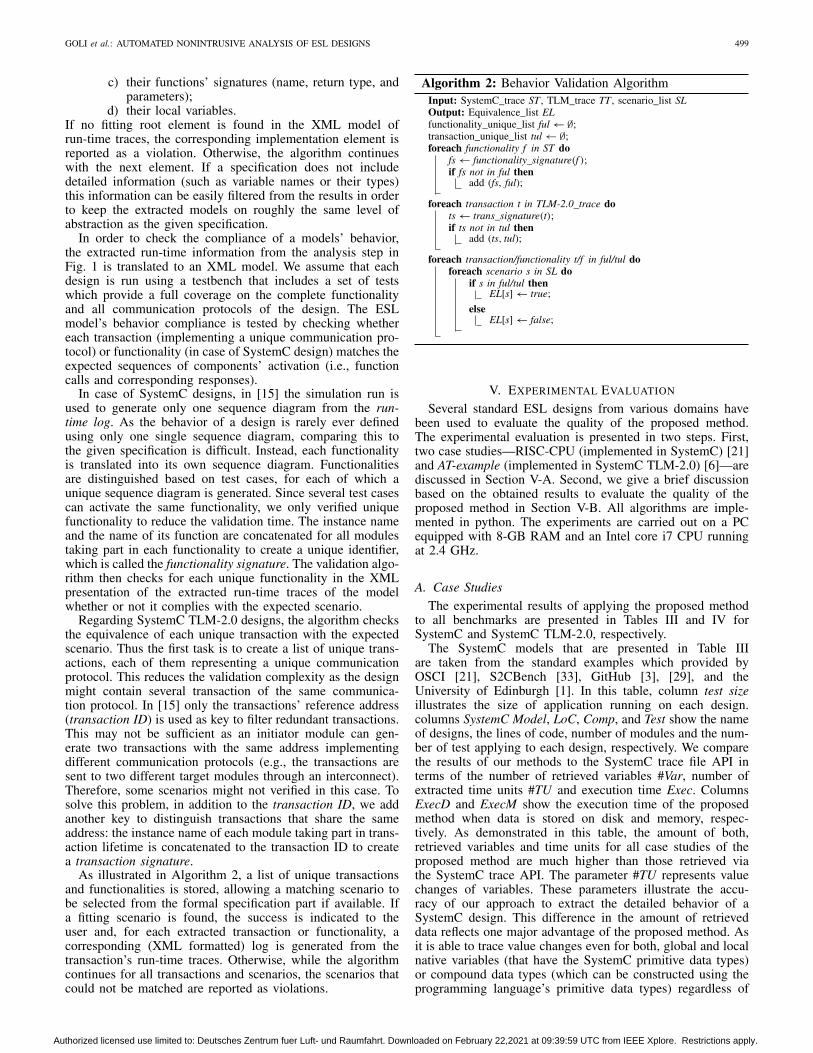
1) RISC-CPU (SystemC Design): The RISC-CPU design isa standard OSCI example implementing a CPU in SystemCusing ten different modules. The instruction set is basedon commercial RISC processors together with MMX-likeinstruction for DSP programs. It consists of more than 39instructions such as arithmetic, logical, branch, floating pointand SIMD (MMX-like). In order to show the intracycle behav-ior, we modified the exec module by adding a combinationalfunction calculating the factorial of the dina input. Thefactorial function is added as an exemplary hardware acceler-ator, computing the factorial computation in a single clockcycle. Integrating such accelerators is a common approachto gain performance for a specific task. Fig. 8 illustrates apart of the generated VCD file of the RISC-CPU system. The
Fig. 8. Part of the generated VCD file of the RISC-CPU example.
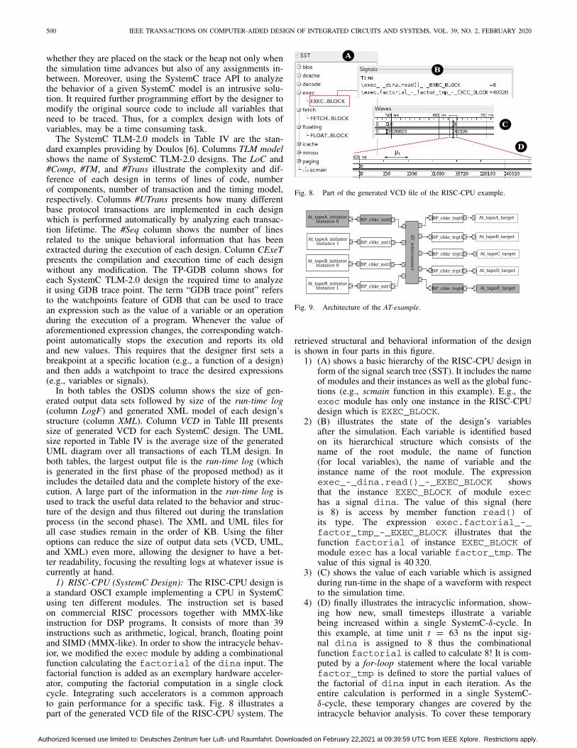
Fig. 9. Architecture of the AT-example.
retrieved structural and behavioral information of the designis shown in four parts in this figure.
1) (A) shows a basic hierarchy of the RISC-CPU design inform of the signal search tree (SST). It includes the nameof modules and their instances as well as the global func-tions (e.g., scmain function in this example). E.g., theexec module has only one instance in the RISC-CPUdesign which is EXEC_BLOCK.
2) (B) illustrates the state of the design’s variablesafter the simulation. Each variable is identified basedon its hierarchical structure which consists of thename of the root module, the name of function(for local variables), the name of variable and theinstance name of the root module. The expressionexec_-_dina.read()_-_EXEC_BLOCK showsthat the instance EXEC_BLOCK of module exechas a signal dina. The value of this signal (hereis 8) is access by member function read() ofits type. The expression exec.factorial_-_factor_tmp_-_EXEC_BLOCK illustrates that thefunction factorial of instance EXEC_BLOCK ofmodule exec has a local variable factor_tmp. Thevalue of this signal is 40 320.
3) (C) shows the value of each variable which is assignedduring run-time in the shape of a waveform with respectto the simulation time.
4) (D) finally illustrates the intracyclic information, show-ing how new, small timesteps illustrate a variablebeing increased within a single SystemC-δ-cycle. Inthis example, at time unit t = 63 ns the input sig-nal dina is assigned to 8 thus the combinationalfunction factorial is called to calculate 8! It is com-puted by a for-loop statement where the local variablefactor_tmp is defined to store the partial values ofthe factorial of dina input in each iteration. As theentire calculation is performed in a single SystemC-δ-cycle, these temporary changes are covered by theintracycle behavior analysis. To cover these temporary
Authorized licensed use limited to: Deutsches Zentrum fuer Luft- und Raumfahrt. Downloaded on February 22,2021 at 09:39:59 UTC from IEEE Xplore. Restrictions apply.
GOLI et al.: AUTOMATED NONINTRUSIVE ANALYSIS OF ESL DESIGNS 501
changes in a single time unit, the Dynamic Informationis analyzed by ICTU module based on Algorithm 1. Asthe maximum amount of assignments within each of thesimulation timesteps is max = 100 and the simulationtime scale is ts = 1 ns, the smallest step within a sin-gle time unit is μt = (ts/ max) = 10 ps. This allowsthe method to store all value changes (even temporaryones).
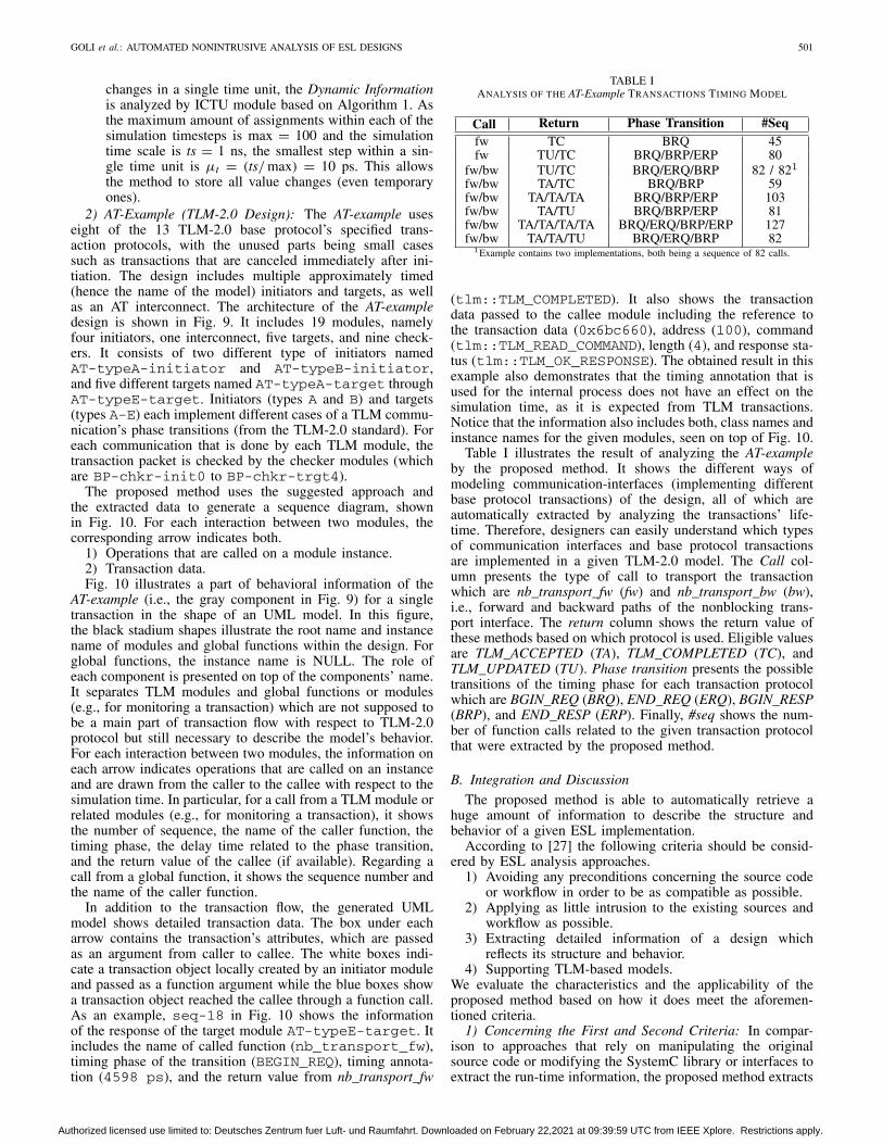
2) AT-Example (TLM-2.0 Design): The AT-example useseight of the 13 TLM-2.0 base protocol’s specified trans-action protocols, with the unused parts being small casessuch as transactions that are canceled immediately after ini-tiation. The design includes multiple approximately timed(hence the name of the model) initiators and targets, as wellas an AT interconnect. The architecture of the AT-exampledesign is shown in Fig. 9. It includes 19 modules, namelyfour initiators, one interconnect, five targets, and nine check-ers. It consists of two different type of initiators namedAT-typeA-initiator and AT-typeB-initiator,and five different targets named AT-typeA-target throughAT-typeE-target. Initiators (types A and B) and targets(types A-E) each implement different cases of a TLM commu-nication’s phase transitions (from the TLM-2.0 standard). Foreach communication that is done by each TLM module, thetransaction packet is checked by the checker modules (whichare BP-chkr-init0 to BP-chkr-trgt4).
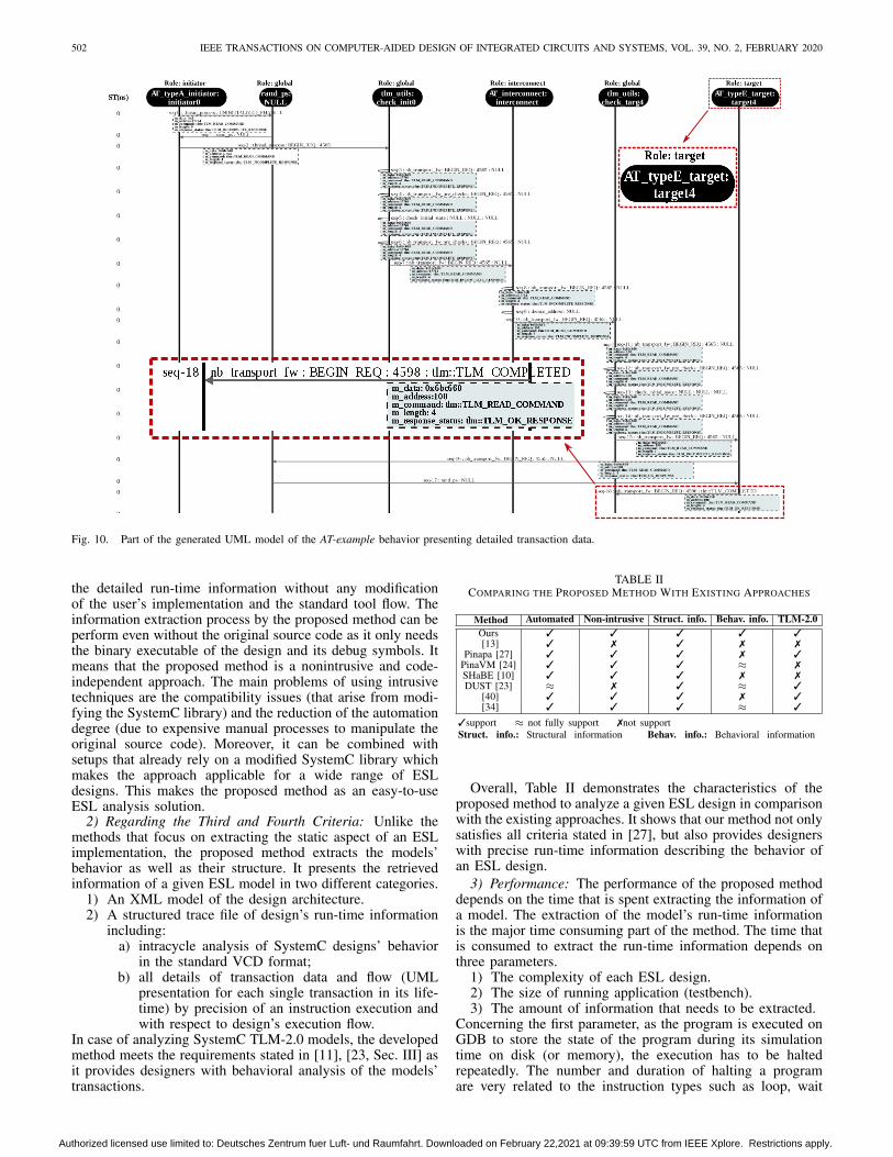
The proposed method uses the suggested approach andthe extracted data to generate a sequence diagram, shownin Fig. 10. For each interaction between two modules, thecorresponding arrow indicates both.
1) Operations that are called on a module instance.2) Transaction data.Fig. 10 illustrates a part of behavioral information of the
AT-example (i.e., the gray component in Fig. 9) for a singletransaction in the shape of an UML model. In this figure,the black stadium shapes illustrate the root name and instancename of modules and global functions within the design. Forglobal functions, the instance name is NULL. The role ofeach component is presented on top of the components’ name.It separates TLM modules and global functions or modules(e.g., for monitoring a transaction) which are not supposed tobe a main part of transaction flow with respect to TLM-2.0protocol but still necessary to describe the model’s behavior.For each interaction between two modules, the information oneach arrow indicates operations that are called on an instanceand are drawn from the caller to the callee with respect to thesimulation time. In particular, for a call from a TLM module orrelated modules (e.g., for monitoring a transaction), it showsthe number of sequence, the name of the caller function, thetiming phase, the delay time related to the phase transition,and the return value of the callee (if available). Regarding acall from a global function, it shows the sequence number andthe name of the caller function.
In addition to the transaction flow, the generated UMLmodel shows detailed transaction data. The box under eacharrow contains the transaction’s attributes, which are passedas an argument from caller to callee. The white boxes indi-cate a transaction object locally created by an initiator moduleand passed as a function argument while the blue boxes showa transaction object reached the callee through a function call.As an example, seq-18 in Fig. 10 shows the informationof the response of the target module AT-typeE-target. Itincludes the name of called function (nb_transport_fw),timing phase of the transition (BEGIN_REQ), timing annota-tion (4598 ps), and the return value from nb_transport_fw
TABLE IANALYSIS OF THE AT-Example TRANSACTIONS TIMING MODEL
(tlm::TLM_COMPLETED). It also shows the transactiondata passed to the callee module including the reference tothe transaction data (0x6bc660), address (100), command(tlm::TLM_READ_COMMAND), length (4), and response sta-tus (tlm::TLM_OK_RESPONSE). The obtained result in thisexample also demonstrates that the timing annotation that isused for the internal process does not have an effect on thesimulation time, as it is expected from TLM transactions.Notice that the information also includes both, class names andinstance names for the given modules, seen on top of Fig. 10.
Table I illustrates the result of analyzing the AT-exampleby the proposed method. It shows the different ways ofmodeling communication-interfaces (implementing differentbase protocol transactions) of the design, all of which areautomatically extracted by analyzing the transactions’ life-time. Therefore, designers can easily understand which typesof communication interfaces and base protocol transactionsare implemented in a given TLM-2.0 model. The Call col-umn presents the type of call to transport the transactionwhich are nb_transport_fw (fw) and nb_transport_bw (bw),i.e., forward and backward paths of the nonblocking trans-port interface. The return column shows the return value ofthese methods based on which protocol is used. Eligible valuesare TLM_ACCEPTED (TA), TLM_COMPLETED (TC), andTLM_UPDATED (TU). Phase transition presents the possibletransitions of the timing phase for each transaction protocolwhich are BGIN_REQ (BRQ), END_REQ (ERQ), BGIN_RESP(BRP), and END_RESP (ERP). Finally, #seq shows the num-ber of function calls related to the given transaction protocolthat were extracted by the proposed method.
B. Integration and Discussion
The proposed method is able to automatically retrieve ahuge amount of information to describe the structure andbehavior of a given ESL implementation.
According to [27] the following criteria should be consid-ered by ESL analysis approaches.
1) Avoiding any preconditions concerning the source codeor workflow in order to be as compatible as possible.
2) Applying as little intrusion to the existing sources andworkflow as possible.
3) Extracting detailed information of a design whichreflects its structure and behavior.
4) Supporting TLM-based models.We evaluate the characteristics and the applicability of theproposed method based on how it does meet the aforemen-tioned criteria.
1) Concerning the First and Second Criteria: In compar-ison to approaches that rely on manipulating the originalsource code or modifying the SystemC library or interfaces toextract the run-time information, the proposed method extracts
Authorized licensed use limited to: Deutsches Zentrum fuer Luft- und Raumfahrt. Downloaded on February 22,2021 at 09:39:59 UTC from IEEE Xplore. Restrictions apply.
502 IEEE TRANSACTIONS ON COMPUTER-AIDED DESIGN OF INTEGRATED CIRCUITS AND SYSTEMS, VOL. 39, NO. 2, FEBRUARY 2020
Fig. 10. Part of the generated UML model of the AT-example behavior presenting detailed transaction data.
the detailed run-time information without any modificationof the user’s implementation and the standard tool flow. Theinformation extraction process by the proposed method can beperform even without the original source code as it only needsthe binary executable of the design and its debug symbols. Itmeans that the proposed method is a nonintrusive and code-independent approach. The main problems of using intrusivetechniques are the compatibility issues (that arise from modi-fying the SystemC library) and the reduction of the automationdegree (due to expensive manual processes to manipulate theoriginal source code). Moreover, it can be combined withsetups that already rely on a modified SystemC library whichmakes the approach applicable for a wide range of ESLdesigns. This makes the proposed method as an easy-to-useESL analysis solution.
2) Regarding the Third and Fourth Criteria: Unlike themethods that focus on extracting the static aspect of an ESLimplementation, the proposed method extracts the models’behavior as well as their structure. It presents the retrievedinformation of a given ESL model in two different categories.
1) An XML model of the design architecture.2) A structured trace file of design’s run-time information
including:a) intracycle analysis of SystemC designs’ behavior
in the standard VCD format;b) all details of transaction data and flow (UML
presentation for each single transaction in its life-time) by precision of an instruction execution andwith respect to design’s execution flow.
In case of analyzing SystemC TLM-2.0 models, the developedmethod meets the requirements stated in [11], [23, Sec. III] asit provides designers with behavioral analysis of the models’transactions.
TABLE IICOMPARING THE PROPOSED METHOD WITH EXISTING APPROACHES
Overall, Table II demonstrates the characteristics of theproposed method to analyze a given ESL design in comparisonwith the existing approaches. It shows that our method not onlysatisfies all criteria stated in [27], but also provides designerswith precise run-time information describing the behavior ofan ESL design.
3) Performance: The performance of the proposed methoddepends on the time that is spent extracting the information ofa model. The extraction of the model’s run-time informationis the major time consuming part of the method. The time thatis consumed to extract the run-time information depends onthree parameters.
1) The complexity of each ESL design.2) The size of running application (testbench).3) The amount of information that needs to be extracted.
Concerning the first parameter, as the program is executed onGDB to store the state of the program during its simulationtime on disk (or memory), the execution has to be haltedrepeatedly. The number and duration of halting a programare very related to the instruction types such as loop, wait
Authorized licensed use limited to: Deutsches Zentrum fuer Luft- und Raumfahrt. Downloaded on February 22,2021 at 09:39:59 UTC from IEEE Xplore. Restrictions apply.
GOLI et al.: AUTOMATED NONINTRUSIVE ANALYSIS OF ESL DESIGNS 503
TABLE IIIEXPERIMENTAL RESULTS FOR ALL SYSTEMC CASE STUDIES
statements and function call. Therefore, more complexityleads to an increased execution time. Experimental results(columns ExecD and ExecM in Table III and columnsETD and ETM in Table IV) show that storing data in themain memory instead of writing it to disk eliminates I/Obottlenecks. This provides designers in average with 21% and19% performance gain for SystemC and SystemC TLM-2.0designs, respectively. As long as new inputs are applied tothe design, the extraction time is increased linearly. Reducingthe amount of data to be extracted (e.g., by limiting theextraction to certain data fields of particular transactions) alsoreduces the overhead of the extraction method.
In order to show how the performance of the proposedmethod is related to the second and third parameters, we eval-uate it by defining two depths of data extraction specifiedby abstract and detailed and two size of applications to berun on each design which are small and large. The abstractdata extraction depth includes all structural information andthe sequence of all component activations. In addition to theinformation retrieved in abstract level, the detailed depth ofdata extraction contains all value changes of modules and func-tions variables during execution. Figs. 11 and 12 illustrate theexecution time of the proposed method for two depths of dataextraction of each design where small and large set of testsare applied to them, respectively. This provides designers withfour corners of the ESL design analysis based on the amountof information to be extracted which are small-abstract (SA),small-details (SD), large-abstract (LA), and large-details (LD).The SA corner shows the fastest analysis and the least amountof information about the design while the LD corner repre-sents the slowest and most precise analysis on a given ESLdesign.
In addition to the abstract and detailed depth of behavioranalysis, the proposed method provides designers with a setof configuration options and parameters in the first phase to
Fig. 11. Run-time analysis of the proposed method based on two depthsof information extraction for small applications running on each SystemCdesign.
generate the GCF script based on the designers’ optimization.This allows them to filter out the information that is notrequired for their analysis and focus on the points of interest.These interactive options are as follows.
1) Filtering some elements of the design, e.g., only tracecertain modules (and their signals).
2) Filtering based on depth of information, e.g., trace onlymodules (and their member functions and variables).
3) Filtering some specific types of function, variables orsignals, e.g., do not trace global functions, local vari-ables or signals of type sc_in.
The proposed method thus provides a designer-chosen trade-off between the amount of information to be extracted and thetime that is needed to do this.
Regarding SystemC TLM-2.0 designs, Table IV showsthe execution time for extracting the static and run-timeinformation and storing them in structured models to a harddrive (column ETD) and memory (column ETM). It shows that
Authorized licensed use limited to: Deutsches Zentrum fuer Luft- und Raumfahrt. Downloaded on February 22,2021 at 09:39:59 UTC from IEEE Xplore. Restrictions apply.
504 IEEE TRANSACTIONS ON COMPUTER-AIDED DESIGN OF INTEGRATED CIRCUITS AND SYSTEMS, VOL. 39, NO. 2, FEBRUARY 2020
TABLE IVEXPERIMENTAL RESULTS FOR ALL TLM-2.0 CASE STUDIES
Fig. 12. Run-time analysis of the proposed method based on two depths ofinformation extraction for large applications running on each SystemC design.
by increasing the numbers of transactions (from small test sizeto large), the execution time increases. The first half of thetable (small test size) illustrates that designs with more linesof code and AT timing model (which including more com-plex base protocol transactions) have larger execution time.Tables III and IV compare the execution time of our methodto analyze a given ESL design with both trace point functional-ity by GDB and its pure compilation and execution time usingGCC. Although GDB’s trace point feature gives a detailedaccess to analyze the ESL model, the required execution timeeven for a simple ESL design lies in an order of hours andfor a complex design, days. The method also needs to be setup manually which makes the solution inapplicable even fora simple model. The required time to analyze an ESL designusing our method in the SD corner is in most cases withina reasonable boundary in comparison to its pure compilationand execution time using GCC. Even for complex designs, itis still in order of minutes.
Although the performance impact of the proposed methodcan be considerable for analyzing a large given ESL design(concerning the LD corner) in comparison to its pure compila-tion and simulation time (worst case the LZW-encoder runningfor about 3 h versus half a minute), there is a wide variety ofuse cases that justify the application of the given approach.
1) The method is able to retrieve detailed traces from,e.g., native variables, the information which has so farbeen limited to manual debugging.
2) The build pipeline remains untouched. This keeps thesetup time low and lets designers quickly evaluateespecially short, questionable test cases. Moreover, anyresults obtained using the given method are sure to beidentical to those that are shown for the productionsystem.
3) In case of third party intellectual property for which onlyan executable binary is available, the proposed methodremains operable. It is the only solution that works onan executable model of the design without availability ofsource code—retrieving the information that is availablevia debug symbols and omitting the unavailable datawithout further setup.
The method can be used at any stage of the design cyclesuch as helping in understanding the designs’ complexity,validation, verification, or synthesis.
4) Memory: As illustrated in Tables III and IV, the largestportion of the generated output data sets (column OSDS)belongs to the run-time log file (column LogF). The reportedsize for all case studies is in order of MB with the worst caseLZW-encoder in LD corner which is about 1 GB. This allowsdesigners to usually store the extracted data in the first phaseof the proposed method (creating the run-time log) in the mainmemory (instead of the hard disk) to reduce I/O overhead andimprove the performance.
5) Limitation: The only precondition of the suggestedapproach is that the executable ESL design must contain debuginformation that is compatible with GDB. While GCC andClang-LLVM are thus supported, Microsoft Visual Studio iscurrently not. Although our methodology is an overall soundanalysis, it does share the inherent performance limitations thatcome with most other run-time-analysis tools build on GDB.
VI. CONCLUSION
In this paper, a new easy-to-use ESL analysis approachwas introduced. The approach is able to analyze SystemCand SystemC TLM-2.0 implementations and translate thecorresponding data to usable formats such as VCD andUML sequence diagrams, respectively. The proposed methodautomatically and nonintrusively extracts both structural andbehavioral information of a given SystemC or SystemCTLM-2.0 model without any modification to the source code ofthe model or the library. Several ESL benchmarks were run toevaluate the effectiveness of the proposed method to analyzeESL designs. The retrieved information in this method canbe effectively utilized for ESL designs validation, verification,and synthesis process.
REFERENCES
[1] The University of Edinburgh School of Informatics-ComputerSystem: LAB 2. Accessed: Jan. 30, 2017. [Online]. Available:http://www.inf.ed.ac.uk/teaching/courses/inf2c-cs/13-14/labs/lab2.html
[2] Cadence Incisive (SimVision), Information Available onCadence Website. Accessed: Jan. 30, 2016. [Online]. Available:http///www.cadence.com
Authorized licensed use limited to: Deutsches Zentrum fuer Luft- und Raumfahrt. Downloaded on February 22,2021 at 09:39:59 UTC from IEEE Xplore. Restrictions apply.
GOLI et al.: AUTOMATED NONINTRUSIVE ANALYSIS OF ESL DESIGNS 505
[3] Freecores. Accessed: Jan. 30, 2017. [Online]. Available:https://github.com/freecores/
[4] Novas Verdi, Information Available on Novas Website. Accessed:Jan. 30, 2016. [Online]. Available: http///www.novas.com
[5] IEEE Standard for Standard SystemC Language Reference Manual,IEEE Standard 1666-2011, 2012, pp. 1–638.
[6] J. Aynsley. TLM-2.0 Base Protocol Checker. Accessed:Jan. 30, 2016. [Online]. Available: https://www.doulos.com/knowhow/systemc/tlm2/at_example
[7] J. Aynsley, Ed., OSCI TLM-2.0 Language Reference Manual, OpenSystemC Initiative, 2009.
[8] D. Berner, J. P. Talpin, H. Patel, D. A. Mathaikuty, and S. K. Shukla,“SystemCXML: An extensible SystemC front end using XML,” in Proc.FDL, 2005, pp. 405–409.
[9] N. Blanc, D. Kroening, and N. Sharygina, “SCOOT: A tool for the anal-ysis of SystemC models,” in Tools and Algorithms for the Constructionand Analysis of Systems (TACAS). Heidelberg, Germany: Springer, 2008,pp. 467–470.
[10] H. Broeders and R. Van Leuken, “Extracting behavior and dynamicallygenerated hierarchy from SystemC models,” in Proc. Design Autom.Conf. (DAC), New York, NY, USA, 2011, pp. 357–362.
[11] F. Doucet, S. Shukla, and R. Gupta, “Introspection in system-level lan-guage frameworks: Meta-level vs. integrated,” in Proc. Design Autom.Test Europe (DATE), 2003, Art. no. 10382.
[12] G. Fey et al., “ParSyC: An efficient SystemC parser,” in Proc. WorkshopSynth. Syst. Integr. Mixed Inf. Technion. (SASIMI), 2004, pp. 148–154.
[13] C. Genz and R. Drechsler, “Overcoming limitations of the SystemCdata introspection,” in Proc. Design Autom. Test Europe Conf. Exhibit.(DATE), Apr. 2009, pp. 590–593.
[14] M. Goli, J. Stoppe, and R. Drechsler, “AIBA: An automated intra-cyclebehavioral analysis for SystemC-based design exploration,” in Proc.ICCD, Scottsdale, AZ, USA, 2016, pp. 360–363.
[15] M. Goli, J. Stoppe, and R. Drechsler, “Automatic equivalence checkingfor SystemC-TLM 2.0 models against their formal specifications,” inProc. DATE, Lausanne, Switzerland, 2017, pp. 630–633.
[16] M. Goli, J. Stoppe, and R. Drechsler, “Automatic protocol compli-ance checking of SystemC TLM-2.0 simulation behavior using timedautomata,” in Proc. ICCD, Boston, MA, USA, 2017, pp. 377–384.
[17] D. Große, R. Drechsler, L. Linhard, and G. Angst, “Efficient automaticvisualization of SystemC designs,” in Proc. Forum Specification DesignLang. (FDL), 2003, pp. 646–658.
[18] A. Habibi and S. Tahar, “Design and verification of SystemC transaction-level models,” IEEE Trans. Very Large Scale Integr. (VLSI) Syst., vol. 14,no. 1, pp. 57–68, Jan. 2006.
[19] P. Herber, J. Fellmuth, and S. Glesner, “Model checking SystemCdesigns using timed automata,” in Proc. CODES+ISSS, 2008,pp. 131–136.
[20] P. Herber and S. Glesner, “A HW/SW co-verification framework forSystemC,” ACM Trans. Embedded Comput. Syst., vol. 12, pp. 1–61,Mar. 2013.
[21] (2016). AS Initiative. [Online]. Available: http://www.accellera.org/downloads/standards/systemc
[22] V. Jain, A. Kumar, and P. Panda, “Exploiting UML based validationfor compliance checking of TLM 2 based models,” Design Autom.Embedded Syst., vol. 16, no. 2, pp. 93–113, 2012.
[23] W. Klingauf and M. Geffken, “Design structure analysis and transactionrecording in SystemC designs: A minimal-intrusive approach,” in Proc.FDL, 2006, pp. 169–177.
[24] K. Marquet and M. Moy, “PinaVM: A SystemC front-end based onan executable intermediate representation,” in Proc. Embedded Softw.(EMSOFT), 2010, pp. 79–88.
[25] G. Martin, B. Bailey, and A. Piziali, ESL Design and Verification: APrescription for Electronic System Level Methodology. San Francisco,CA, USA: Morgan Kaufmann, 2007.
[26] M. Moy, F. Maraninchi, and L. Maillet-Contoz, “LusSy: A toolbox forthe analysis of systems-on-a-chip at the transactional level,” in Proc.Appl. Concurrency Syst. Design (ACSD), 2005, pp. 26–35.
[27] M. Moy, F. Maraninchi, and L. Maillet-Contoz, “Pinapa: An extractiontool for SystemC descriptions of systems-on-a-chip,” in Proc. EmbeddedSoftw. (EMSOFT), New York, NY, USA, 2005, pp. 317–324.
[28] W. Mueller et al., “UML for ESL design: Basic principles, tools, andapplications,” in Proc. IEEE/ACM Int. Conf. Comput.-Aided Design,San Jose, CA, USA, 2006, pp. 73–80.
[29] Orahyn. LZW-Encoder. Accessed: Jan. 30, 2017. [Online]. Available:https://github.com/arshadri/lzw_systemc/tree/master/systemc
[30] H. D. Patel, D. A. Mathaikutty, D. Berner, and S. K. Shukla,“SystemCXML: An extensible SystemC front end using XML,” inProc. Forum Specification Design Lang., Lausanne, Switzerland, 2005,pp. 27–30.
[31] E. Riccobene, P. Scandurra, A. Rosti, and S. Bocchio, “A UML 2.0profile for SystemC: Toward high-level SoC design,” in Proc. ACM Int.Conf. Embedded Softw. (EMSOFT), 2005, pp. 138–141.
[32] J. Rumbaugh, I. Jacobson, and G. Booch, Eds., The Unified ModelingLanguage Reference Manual. Boston, MA, USA: Addison-Wesley, 1999.
[33] B. C. Schafer and A. Mahapatra, “S2CBench: Synthesizable SystemCbenchmark suite for high-level synthesis,” IEEE Embedded Syst. Lett.,vol. 6, no. 3, pp. 53–56, Sep. 2014.
[34] T. Schmidt, G. Liu, and R. Dömer, “Automatic generation of threadcommunication graphs from SystemC source code,” in Proc. 19thInt. Workshop Softw. Compilers Embedded Syst. (SCOPES), 2016,pp. 108–115.
[35] T. Schubert and W. Nebel, “The quiny SystemCTM front end:Self-synthesising designs,” in Proc. Selected Contributions ForumSpecification Design Lang. (FDL), 2007, pp. 93–109.
[36] C. Schulz-Key, M. Winterholer, T. Schweizer, T. Kuhn, and W. Rosentiel,“Object-oriented modeling and synthesis of SystemC specifications,” inProc. ASP-DAC, 2004, pp. 238–243.
[37] W. Snyder. SystemPerl Homepage. Accessed: Jan. 30, 2016. [Online].Available: http://www.veripool.com/systemperl.html
[38] R. Stallman and C. Support, Debugging With GDB: The GNU Source-Level Debugger, 9th ed. Boston, MA, USA: Free Softw. Found., 2010.
[39] J. Stoppe and R. Drechsler, “Analyzing SystemC designs: SystemC anal-ysis approaches for varying applications,” Sensors, vol. 15, no. 5, 2015,Art. no. 10399.
[40] J. Stoppe, R. Wille, and R. Drechsler, “Data extraction from SystemCdesigns using debug symbols and the SystemC API,” in Proc. IEEEComput. Soc. Annu. Symp. VLSI (ISVLSI), 2013, pp. 26–31.
[41] J. Stoppe, R. Wille, and R. Drechsler, “Validating SystemC implemen-tations against their formal specifications,” in Proc. 27th Symp. Integr.Circuits Syst. Design (SBCCI), 2014, pp. 1–8.
Mehran Goli (S’16) received the B.Sc. degree fromthe University of Shahid Beheshti, Tehran, Iran, in2012, and the M.Sc. degree from the University ofTehran, Tehran, in 2015, both in computer engineer-ing. He is currently pursuing the Ph.D. degree withthe Group of Computer Architecture, University ofBremen, Bremen, Germany.
His current research interests include system leveldesign, verification, and validation.
Jannis Stoppe received the Dr.-Ing. degree incomputer science from the University of Bremen,Bremen, Germany, in 2017.
He recently joined the German Aerospace CenterDLR, Institute for the Protection of MaritimeInfrastructures, Bremerhaven, Germany, where hecurrently leads the Situational Awareness Group,focusing on sensor fusion and data analysis. Hiscurrent research interest includes development ofnew techniques for analyzing high-level hardwaredescriptions written in SystemC.
Rolf Drechsler (F’15) received the Diploma andDr. Phil.Nat. degrees in computer science fromJ. W. Goethe University Frankfurt am Main,Frankfurt, Germany, in 1992 and 1995, respectively.
He was with the Institute of Computer Science,Albert-Ludwigs University, Freiburg im Breisgau,Germany, from 1995 to 2000, and the CorporateTechnology Department, Siemens AG, Munich,Germany, from 2000 to 2001. Since 2001, hehas been with the University of Bremen, Bremen,Germany, where he is currently a Full Professor and
the Head of the Group for Computer Architecture, Institute of ComputerScience. In 2011, he additionally became the Director of the Cyber-PhysicalSystems Group, German Research Center for Artificial Intelligence (DFKI),Bremen, where he is a Co-Founder of the Graduate School of EmbeddedSystems and the Coordinator of the Graduate School “System Design” fundedwithin the German Excellence Initiative. His current research interest includesdevelopment and design of data structures and algorithms with a focus on cir-cuit and system design.
Dr. Drechsler was a recipient of the Best Paper Award at HVC in 2006,FDL in 2007 and 2010, DDECS in 2010, and ICCAD in 2013 and 2018. Hewas the Symposium Chair of ISMVL 1999 and 2014 and ETS 2018, and theTopic Chair for “Formal Verification” DATE 2004, DATE 2005, DAC 2010,as well as DAC 2011. He is an Associate Editor of the IEEE TRANSACTIONS
ON COMPUTER-AIDED DESIGN OF INTEGRATED CIRCUITS AND SYSTEMS,the IEEE TRANSACTIONS ON VERY LARGE SCALE INTEGRATION (VLSI)SYSTEMS, IET Cyber-Physical Systems: Theory and Applications, theInternational Journal on Multiple-Valued Logic and Soft Computing, andACM Journal on Emerging Technologies in Computing Systems. He wasa Program Committee Member of numerous conferences, including DAC,ICCAD, DATE, ASP-DAC, FDL, MEMOCODE, and FMCAD.
Authorized licensed use limited to: Deutsches Zentrum fuer Luft- und Raumfahrt. Downloaded on February 22,2021 at 09:39:59 UTC from IEEE Xplore. Restrictions apply.