Embed Size (px)
Citation preview

Laser Based Spark Ignition forReciprocating Engines
Presenter: Mike McMillian
September 16, 2002Natural Gas Infrastructure Reliability Industry
Forums

2K-2571
Introduction: Why Laser Ignition?
• Regulations on NOx Emissions Have continue to force Operation ofNatural Gas Engines to Leaner Air/Fuel Ratios
• Lean Air/Fuel Ratios Are More Difficult to Ignite, ConventionalSystems Require High Ignition Energies
• Natural Gas Is More Difficult to Ignite Than Gasoline due to theStrong C-H Bond Energy− Laser Light Is Monochromatic, So Selective Chemistry
Becomes a Possible Option.
• Due to Increased Ignition Coil Energy, Spark Plug Service Life IsVery Low for Natural Gas Engines− Laser ignition offers the potential for extended service life
• Rugged lasers are available for numerous industrial processes
• Potential for Improved Durability!
2K-2571
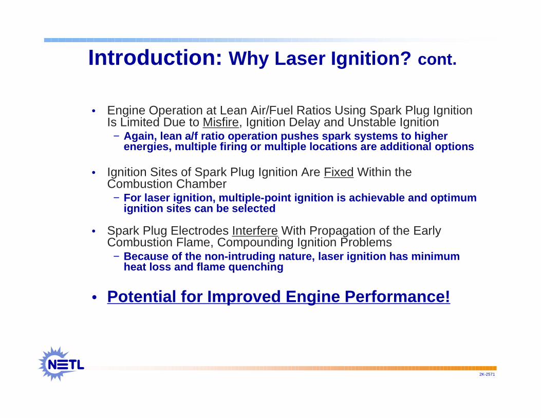
Introduction: Why Laser Ignition? cont.
• Engine Operation at Lean Air/Fuel Ratios Using Spark Plug IgnitionIs Limited Due to Misfire, Ignition Delay and Unstable Ignition− Again, lean a/f ratio operation pushes spark systems to higher
energies, multiple firing or multiple locations are additional options
• Ignition Sites of Spark Plug Ignition Are Fixed Within theCombustion Chamber− For laser ignition, multiple-point ignition is achievable and optimum
ignition sites can be selected
• Spark Plug Electrodes Interfere With Propagation of the EarlyCombustion Flame, Compounding Ignition Problems− Because of the non-intruding nature, laser ignition has minimum
heat loss and flame quenching
• Potential for Improved Engine Performance!
2K-2571
TECHNOLOGY STATUS
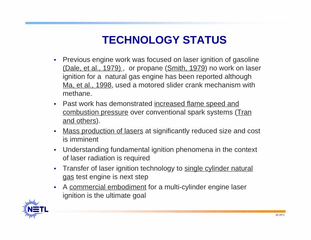
• Previous engine work was focused on laser ignition of gasoline(Dale, et al., 1979) , or propane (Smith, 1979) no work on laserignition for a natural gas engine has been reported althoughMa, et al., 1998, used a motored slider crank mechanism withmethane.
• Past work has demonstrated increased flame speed andcombustion pressure over conventional spark systems (Tranand others).
• Mass production of lasers at significantly reduced size and costis imminent
• Understanding fundamental ignition phenomena in the contextof laser radiation is required
• Transfer of laser ignition technology to single cylinder naturalgas test engine is next step
• A commercial embodiment for a multi-cylinder engine laserignition is the ultimate goal

2K-2571
Research Needs
• Fundamental Level− Basic science regarding ignition of combustible mixtures− Multiple pulse ignition− Multiple Point Ignition
• Practical Level: Research Needs Leading to Commercialization− Laser induced optical damage/Beam Delivery− Particle deposits− Laser System− Intelligent Control− Laser Distribution

2K-2571
Goals and Objectives
• Develop scientific and engineering foundationfor laser spark ignition in reciprocatingengines−Single Cylinder−Single Point Ignition−Laser beam distribution−Multipoint ignition−Multipulse ignition
NETL ActivitiesNETL Activities
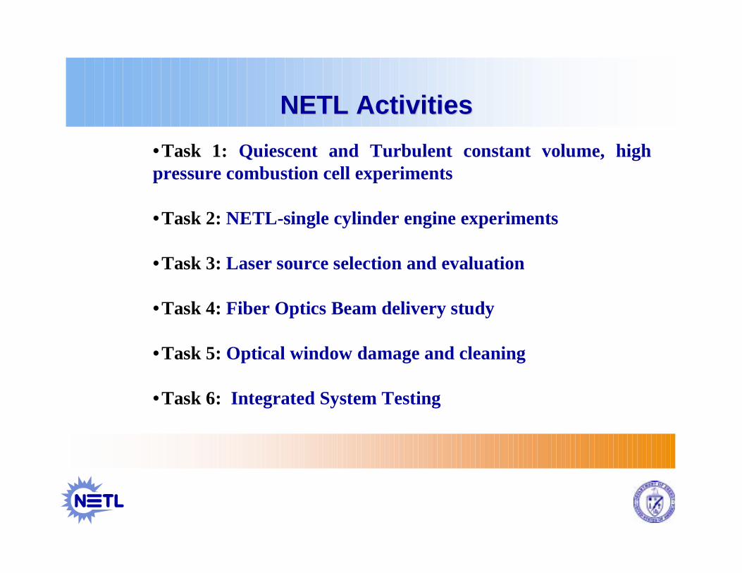
•Task 1: Quiescent and Turbulent constant volume, highpressure combustion cell experiments
•Task 2: NETL-single cylinder engine experiments
•Task 3: Laser source selection and evaluation
•Task 4: Fiber Optics Beam delivery study
•Task 5: Optical window damage and cleaning
•Task 6: Integrated System Testing

2K-2571
Summary of NETL Laser Ignition Workto-date
• Laser ignition tests using a constant volume cell and turbulent jetdiffusion flames have been carried out
• Investigated effects of optical properties and fuel properties on theignition probability and the minimum ignition energy
• Developed theoretical ignition model for laser ignition
• Considered benefits of laser ignition and its potential applications for gasengines
• Identified many technical difficulties and potential solutions
2K-2571
Summary of NETL Laser Ignition Workto-date (cont.)
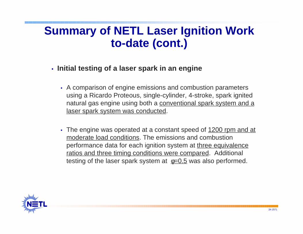
• Initial testing of a laser spark in an engine
• A comparison of engine emissions and combustion parametersusing a Ricardo Proteous, single-cylinder, 4-stroke, spark ignitednatural gas engine using both a conventional spark system and alaser spark system was conducted.
• The engine was operated at a constant speed of 1200 rpm and atmoderate load conditions. The emissions and combustionperformance data for each ignition system at three equivalenceratios and three timing conditions were compared. Additionaltesting of the laser spark system at φ=0.5 was also performed.
2K-2571
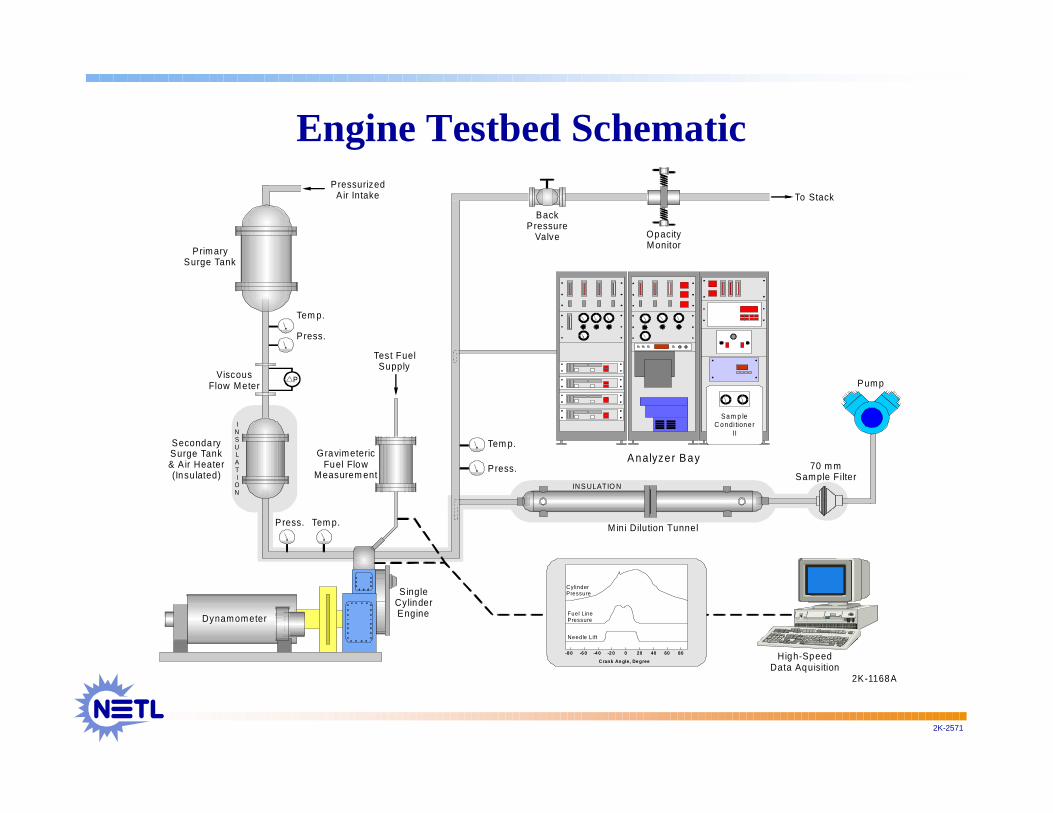
Engine Testbed Schematic
Press.
Tem p.
-8 0 -6 0 -4 0 -2 0 0 20 40 60 80
Crank An gle, De gree
CylinderPressure
Fuel LinePressure
Needle Lift
P ressurizedAir Intake
ViscousFlow Meter
SecondarySurge Tank& A ir Heater(Insulated)
PrimarySurge Tank
Dynamometer
S ingleCylinderEngine
A nalyze r B ay
High-SpeedData Aquisition
Mini Dilution Tunnel
Pump
70 m mSample Filter
Press.
Press.
Tem p.
Tem p.
BackPressure
Valve OpacityMonitor
To Stack
P
Test FuelSupply
GravimetericFuel Flow
Measurem ent
2K-1168A
INSULATI
ON
Sa m p leC o n di tion e r
II
IN S ULATIO N
2K-2571
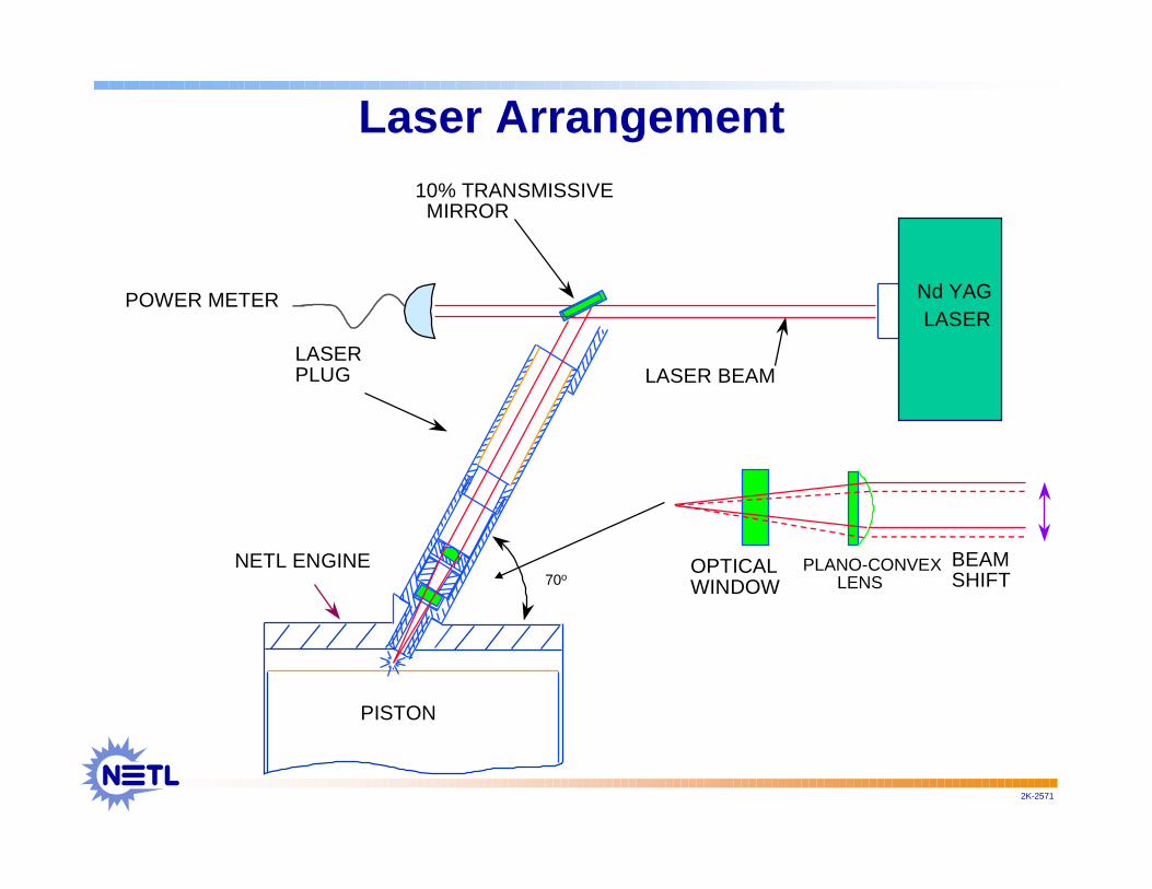
PISTON
NETL ENGINE
LASERPLUG
10% TRANSMISSIVE MIRROR
LASER BEAM
Nd YAG LASER
70oOPTICALWINDOW
PLANO-CONVEX LENS
BEAMSHIFT
POWER METER
Laser Arrangement

2K-2571
Initial Single Cylinder EngineTesting Results

2K-2571
Coefficient of Variation (COV) of theIndicated Mean Effective Pressure (IMEP)
IMEP = (Pnr/VdN)
0
2
4
6
8
10
12
14
35 25 15
Timin g ( o b td c )
Plug,Phi=0.6Laser,Phi=0.6Plug,Phi=0.55Laser,Phi=0.55Plug,Phi=0.525Laser,
2K-2571
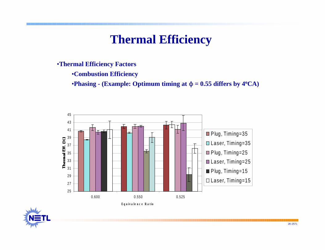
Thermal Efficiency
25
27
29
31
33
35
37
39
41
43
45
0.600 0.550 0.525
E q u iv a le n c e R a t io
P lug , Tim ing=35
Laser, Tim ing=35
P lug , Tim ing=25
Laser, Tim ing=25
P lug , Tim ing=15
Laser, Tim ing=15
•Thermal Efficiency Factors
•Combustion Efficiency
•Phasing - (Example: Optimum timing at 11 = 0.55 differs by 4oCA)

2K-2571
Ignition Delay, 5%-50% Burn Rate and Location ofMaximum Heat Release Rate
0
5
10
15
20
25
30
35 25 15
Timing (obtdc)
"Ig
niti
on
Del
ay"
(oC
A)
Plug,Phi=0.6Laser,Phi=0.6Plug,Phi=0.55Laser,Phi=0.55Plug,Phi=0.525Laser,Phi=0.525
0
5
10
15
20
25
35 25 15
Timing (obtdc)
5%-5
0% B
urn
Du
ratio
n (o
CA
)
Plug,Phi=0.6Laser,Phi=0.6Plug,Phi=0.55Laser,Phi=0.55Plug,Phi=0.525Laser,Phi=0.525
-5
0
5
10
15
20
25
30
35
35 25 15
Timing (obtdc)
Max
, HR
R L
oc
(oC
A)
Plug,Phi=0.6Laser,Phi=0.6Plug,Phi=0.55Laser,Phi=0.55Plug,Phi=0.525Laser,Phi=0.525
-60 -50 -40 -30 -20 -10 0 10 20 30 40 50 60oCA
HH
R [
kJ/m
3]
-12
-6
0
6
12
18
24
30
36
42
48
2K-2571
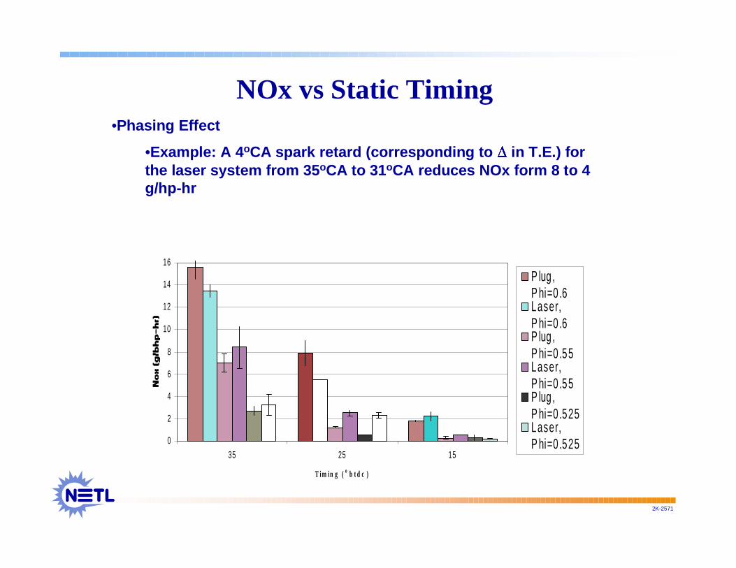
NOx vs Static Timing
0
2
4
6
8
10
12
14
16
35 25 15
T i m in g ( o b t d c )
P lug ,P hi=0 .6Laser,P hi=0 .6P lug ,P hi=0 .55Laser,P hi=0 .55P lug ,P hi=0 .525Laser,P hi=0 .525
•Phasing Effect
•Example: A 4oCA spark retard (corresponding to �� in T.E.) forthe laser system from 35oCA to 31oCA reduces NOx form 8 to 4g/hp-hr

2K-2571
THC vs Static Timing
0
5
10
15
20
25
35 25 15
T im in g ( o b t d c )
P lug,P hi=0.6Laser,P hi=0.6P lug,P hi=0.55Laser,P hi=0.55P lug,P hi=0.525Laser,P hi=0.525

2K-2571
CO vs Static Timing
0 .0
0 .5
1 .0
1 .5
2 .0
2 .5
3 .0
3 .5
4 .0
35 25 15
Tim ing (obtdc)
CO
(g
/bh
p-h
r
P lug ,P hi=0 .6Laser,P hi=0 .6P lug ,P hi=0 .55Laser,P hi=0 .55P lug ,P hi=0 .525Laser,P hi=0 .525

2K-2571
Conclusions: Engine Testing to Date
• Significantly improved combustion performance was obtained atlean equivalence ratio/retarded timing conditions using the laserspark system.
• Window fouling due to deposition of products of combustion wasnot apparent during approximately 10 hours of laser engineoperation.
• NOx emissions were generally higher with laser spark operation.However timing optimization was not attempted.
• Hydrocarbon emissions were generally lower with laser operation atthe lower equivalence ratio and retarded timing settings.
• Emissions of CO were generally higher with laser spark. Again,improvement in CO emissions may be possible with timingoptimization.
•• Laser spark operation provided stable combustion at conditionsLaser spark operation provided stable combustion at conditionsleaner than achievable with the conventional spark ignition system.leaner than achievable with the conventional spark ignition system.
Laser Equivalence Ratio = 0.5
Timing (obtdc) 35 25 15
Torque (nm) 130.44 121.35 67.84
Therm eff. (%)41.85 39.02 21.73
NOx Rate (g/bhp-hr)1.05 0.20 0.13
CO Rate (g/bhp-hr)2.52 2.82 7.09
THC Rate (g/bhp-hr)10.58 14.44 33.92
Pmax (bar)39.11 28.69 21.08
Pmax Loc (oCA)9.50 12.75 1.95
IMEP COV1.31 3.72 18.25
5%-50% BurnDuration (oCA) 15.98 18.50 23.75
SOC (oCA)-8.48 -1.75 8.23
Ignition Delay (oCA)26.53 23.25 23.23
HRR Peak (KJ/M3)41.05 28.90 16.25
HRR Peak Loc (oCA)5.00 12.00 21.00
2K-2571
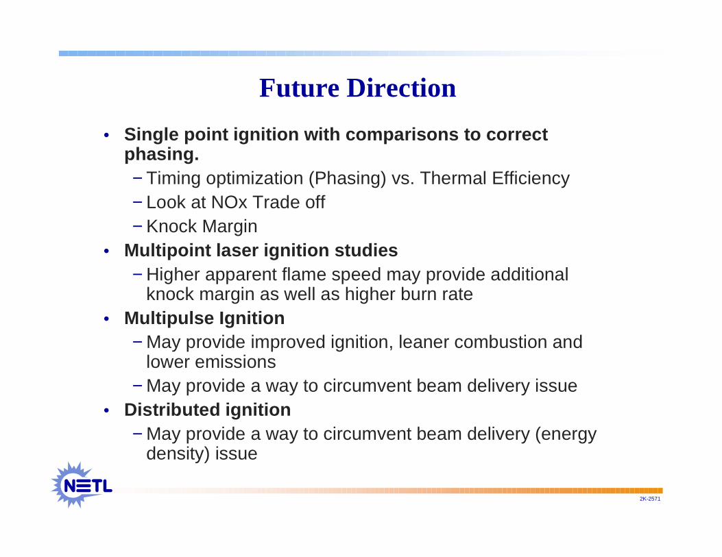
Future Direction
• Single point ignition with comparisons to correctphasing.− Timing optimization (Phasing) vs. Thermal Efficiency− Look at NOx Trade off− Knock Margin
• Multipoint laser ignition studies− Higher apparent flame speed may provide additional
knock margin as well as higher burn rate• Multipulse Ignition
− May provide improved ignition, leaner combustion andlower emissions
− May provide a way to circumvent beam delivery issue• Distributed ignition
− May provide a way to circumvent beam delivery (energydensity) issue

2K-2571
Collaboration Efforts
• Laser-spark ignition Working Group− Initial meeting on or about October 8-9, 2002−Organized by ANL (David Livengood)

2K-2571
The End……Thanks!

Technical Barriers/SolutionsTechnical Barriers/Solutions
BarriersBarriers
•• Laser Technology Laser Technology (Being(BeingEvaluated)Evaluated)
•• Optics Optics
•• Particulate Deposition Particulate Deposition
•• Focal Length Effects Focal Length Effects
PotentialPotential SolutionsSolutions
•• Distributed System Distributed System
•• Improved Fiber Optics Improved Fiber Opticsfor beam delivery, qualityfor beam delivery, qualityopticsoptics
•• Multi-pulse Mode Multi-pulse Mode