Embed Size (px)
Citation preview
800-456-7100 I www.paladinlcg.com 503 Gay Street, Delhi, IA 52223, United States of America
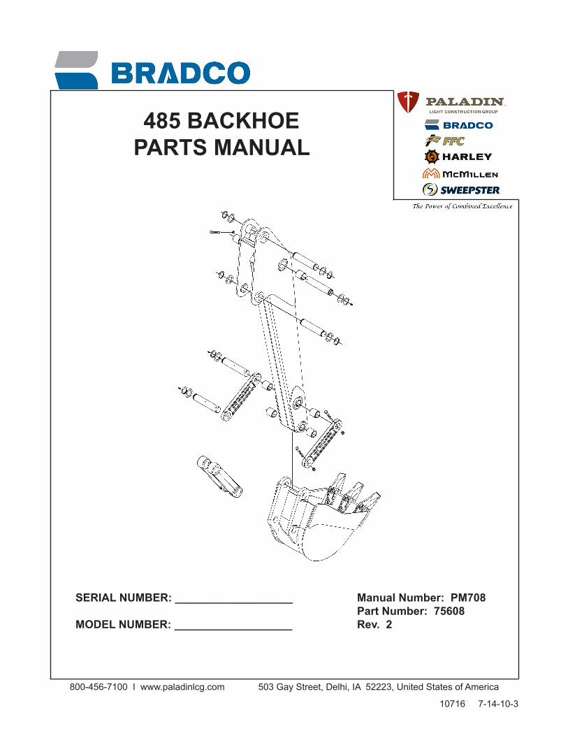
SERIALNUMBER:___________________ ManualNumber:PM708 PartNumber:75608 MODELNUMBER:___________________ Rev.2
485BACKHOEPARTSMANUAL
10716 7-14-10-3

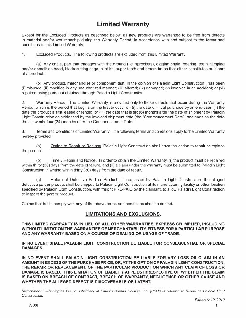
Limited WarrantyExcept for the Excluded Products as described below, all new products are warranted to be free from defects in material and/or workmanship during the Warranty Period, in accordance with and subject to the terms and conditions of this Limited Warranty.
1. Excluded Products. The following products are excluded from this Limited Warranty:
(a) Any cable, part that engages with the ground (i.e. sprockets), digging chain, bearing, teeth, tamping and/or demolition head, blade cutting edge, pilot bit, auger teeth and broom brush that either constitutes or is part of a product.
(b) Any product, merchandise or component that, in the opinion of Paladin Light Construction1, has been (i) misused; (ii) modified in any unauthorized manner; (iii) altered; (iv) damaged; (v) involved in an accident; or (vi) repaired using parts not obtained through Paladin Light Construction.
2. Warranty Period. The Limited Warranty is provided only to those defects that occur during the Warranty Period, which is the period that begins on the first to occur of: (i) the date of initial purchase by an end-user, (ii) the date the product is first leased or rented, or (iii) the date that is six (6) months after the date of shipment by Paladin Light Construction as evidenced by the invoiced shipment date (the “Commencement Date”) and ends on the date that is twenty-four (24) months after the Commencement Date.
3. Terms and Conditions of Limited Warranty. The following terms and conditions apply to the Limited Warranty hereby provided:
(a) Option to Repair or Replace. Paladin Light Construction shall have the option to repair or replace the product.
(b) Timely Repair and Notice. In order to obtain the Limited Warranty, (i) the product must be repaired within thirty (30) days from the date of failure, and (ii) a claim under the warranty must be submitted to Paladin Light Construction in writing within thirty (30) days from the date of repair.
(c) Return of Defective Part or Product. If requested by Paladin Light Construction, the alleged defective part or product shall be shipped to Paladin Light Construction at its manufacturing facility or other location specified by Paladin Light Construction, with freight PRE-PAID by the claimant, to allow Paladin Light Construction to inspect the part or product.
Claims that fail to comply with any of the above terms and conditions shall be denied.
LIMITATIONS AND EXCLUSIONS.
THIS LIMITED WARRANTY IS IN LIEU OF ALL OTHER WARRANTIES, EXPRESS OR IMPLIED, INCLUDING WITHOUT LIMITATION THE WARRANTIES OF MERCHANTABILITY, FITNESS FOR A PARTICULAR PURPOSE AND ANY WARRANTY BASED ON A COURSE OF DEALING OR USAGE OF TRADE.
IN NO EVENT SHALL PALADIN LIGHT CONSTRUCTION BE LIABLE FOR CONSEQUENTIAL OR SPECIAL DAMAGES.
IN NO EVENT SHALL PALADIN LIGHT CONSTRUCTION BE LIABLE FOR ANY LOSS OR CLAIM IN AN AMOUNT IN EXCESS OF THE PURCHASE PRICE, OR, AT THE OPTION OF PALADIN LIGHT CONSTRUCTION, THE REPAIR OR REPLACEMENT, OF THE PARTICULAR PRODUCT ON WHICH ANY CLAIM OF LOSS OR DAMAGE IS BASED. THIS LIMITATION OF LIABILITY APPLIES IRRESPECTIVE OF WHETHER THE CLAIM IS BASED ON BREACH OF CONTRACT, BREACH OF WARRANTY, NEGLIGENCE OR OTHER CAUSE AND WHETHER THE ALLEGED DEFECT IS DISCOVERABLE OR LATENT.
1Attachment Technologies Inc., a subsidiary of Paladin Brands Holding, Inc. (PBHI) is referred to herein as Paladin Light Construction.
February 10, 201075608 1

THIS PAGEIS INTENTIONALLY
BLANK
2 75608
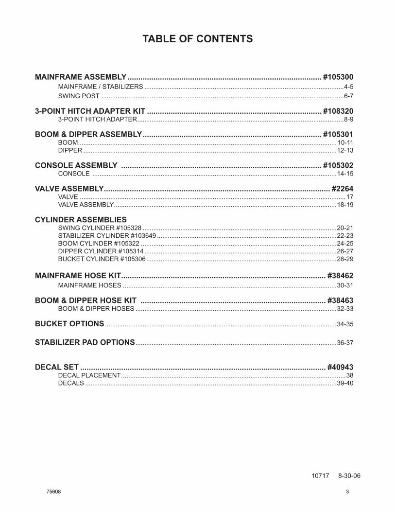
TABLE OF CONTENTS
10717 8-30-06
mAiNFrAmE ASSEmBLy .......................................................................................... #105300 MAINFRAME / STABILIZERS ...............................................................................................................4-5 SWING POST .......................................................................................................................................6-7
3-POiNT HiTCH ADAPTEr KiT ................................................................................. #108320 3-POINT HITCH ADAPTER ...................................................................................................................8-9
BOOm & DiPPEr ASSEmBLy ................................................................................... #105301 BOOM ................................................................................................................................................10-11 DIPPER .............................................................................................................................................12-13
CONSOLE ASSEmBLy ............................................................................................. #105302 CONSOLE ........................................................................................................................................14-15
VALVE ASSEmBLy ......................................................................................................... #2264 VALVE ....................................................................................................................................................17 VALVE ASSEMBLY ............................................................................................................................18-19
CyLiNDEr ASSEmBLiES SWING CYLINDER #105328 ............................................................................................................20-21 STABILIZER CYLINDER #103649 ....................................................................................................22-23 BOOM CYLINDER #105322 .............................................................................................................24-25 DIPPER CYLINDER #105314 ...........................................................................................................26-27 BUCKET CYLINDER #105306 ..........................................................................................................28-29
mAiNFrAmE HOSE KiT ............................................................................................... #38462 MAINFRAME HOSES .......................................................................................................................30-31
BOOm & DiPPEr HOSE KiT ...................................................................................... #38463 BOOM & DIPPER HOSES ................................................................................................................32-33
BUCKET OPTiONS .................................................................................................................................34-35
STABiLiZEr PAD OPTiONS ................................................................................................................36-37
DECAL SET .................................................................................................................. #40943 DECAL PLACEMENT .............................................................................................................................38 DECALS ............................................................................................................................................39-40
75608 3
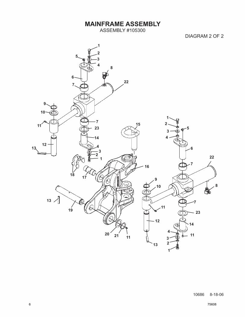
MAINFRAME ASSEMBLY
10684 8-18-06
ASSEMBLY #105300DIAGRAM 1 OF 2
1
2
3
4
5
67
89
2
4
5
5
67
10
10
9
9
9
8
8
8
11
12 13
14
7
77
7
3
15
4 75608
MAINFRAME ASSEMBLY
10685 8-18-06
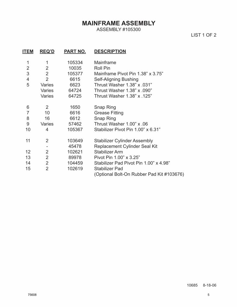
ITEM REQ’D PART NO. DESCRIPTION
1 1 105334 Mainframe 2 2 10035 Roll Pin 3 2 105377 Mainframe Pivot Pin 1.38” x 3.75” 4 2 6615 Self-Aligning Bushing 5 Varies 6623 Thrust Washer 1.38” x .031” Varies 64724 Thrust Washer 1.38” x .090” Varies 64725 Thrust Washer 1.38” x .125”
6 2 1650 Snap Ring 7 10 6616 Grease Fitting 8 16 6612 Snap Ring 9 Varies 57462 Thrust Washer 1.00” x .06 10 4 105367 Stabilizer Pivot Pin 1.00” x 6.31”
11 2 103649 Stabilizer Cylinder Assembly - 45478 Replacement Cylinder Seal Kit 12 2 102621 Stabilizer Arm 13 2 89978 Pivot Pin 1.00” x 3.25” 14 2 104459 Stabilizer Pad Pivot Pin 1.00” x 4.98” 15 2 102619 Stabilizer Pad (Optional Bolt-On Rubber Pad Kit #103676)
ASSEMBLY #105300 LIST 1 OF 2
75608 5
MAINFRAME ASSEMBLY
10686 8-18-06
ASSEMBLY #105300DIAGRAM 2 OF 2
1
234
5
6
7
8
9
10
11
1213
14
15
16
1718
19
12
34
5
1
234
12
34 6
7
7
98
23
10
11
11
11
12
13
14
20
13
21
22
227
23
6 75608
MAINFRAME ASSEMBLY
10687 8-18-06
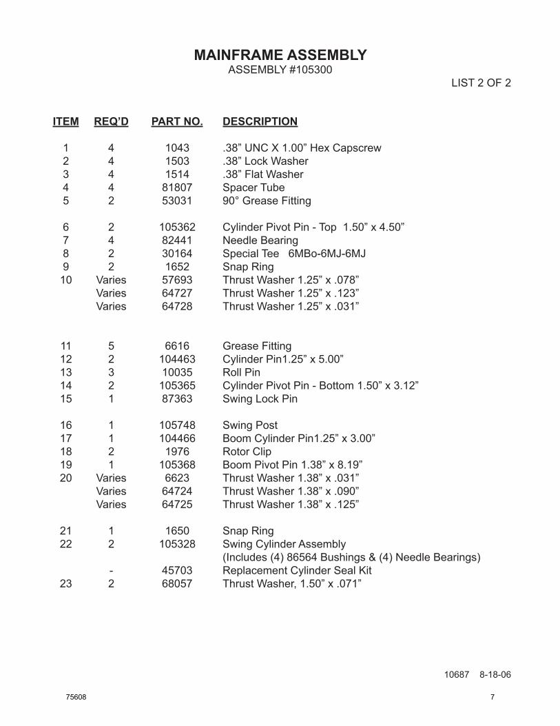
ITEM REQ’D PART NO. DESCRIPTION
1 4 1043 .38” UNC X 1.00” Hex Capscrew 2 4 1503 .38” Lock Washer 3 4 1514 .38” Flat Washer 4 4 81807 Spacer Tube 5 2 53031 90° Grease Fitting
6 2 105362 Cylinder Pivot Pin - Top 1.50” x 4.50” 7 4 82441 Needle Bearing 8 2 30164 Special Tee 6MBo-6MJ-6MJ 9 2 1652 Snap Ring 10 Varies 57693 Thrust Washer 1.25” x .078” Varies 64727 Thrust Washer 1.25” x .123” Varies 64728 Thrust Washer 1.25” x .031”
11 5 6616 Grease Fitting 12 2 104463 Cylinder Pin1.25” x 5.00” 13 3 10035 Roll Pin 14 2 105365 Cylinder Pivot Pin - Bottom 1.50” x 3.12” 15 1 87363 Swing Lock Pin
16 1 105748 Swing Post 17 1 104466 Boom Cylinder Pin1.25” x 3.00” 18 2 1976 Rotor Clip 19 1 105368 Boom Pivot Pin 1.38” x 8.19” 20 Varies 6623 Thrust Washer 1.38” x .031” Varies 64724 Thrust Washer 1.38” x .090” Varies 64725 Thrust Washer 1.38” x .125”
21 1 1650 Snap Ring 22 2 105328 Swing Cylinder Assembly (Includes (4) 86564 Bushings & (4) Needle Bearings) - 45703 Replacement Cylinder Seal Kit 23 2 68057 Thrust Washer, 1.50” x .071”
ASSEMBLY #105300LIST 2 OF 2
75608 7
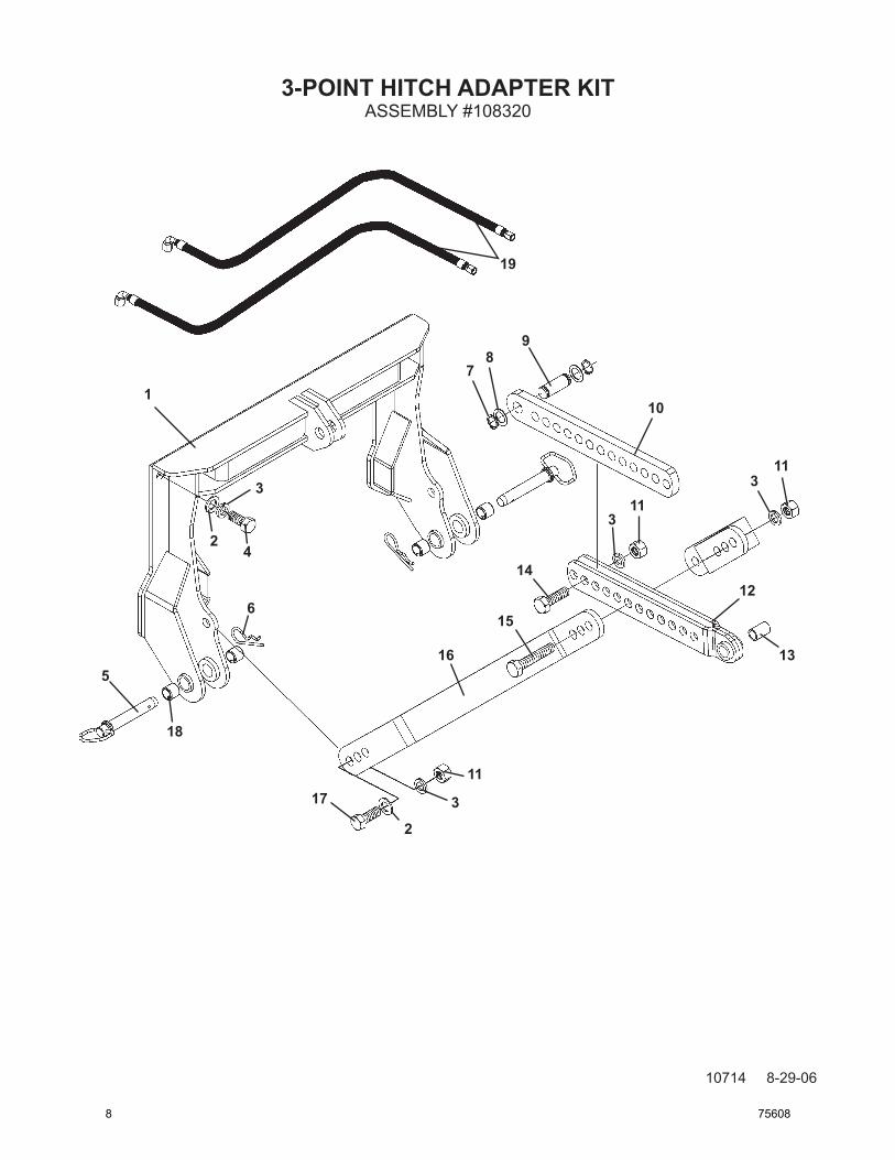
3-POINT HITCH ADAPTER KIT
10714 8-29-06
ASSEMBLY #108320
1
2
3
4
5
6
78
9
10
113
3
3
2
1214
15
16
17
11
11
18
13
19
8 75608
3-POINT HITCH ADAPTER KIT
10715 8-29-06
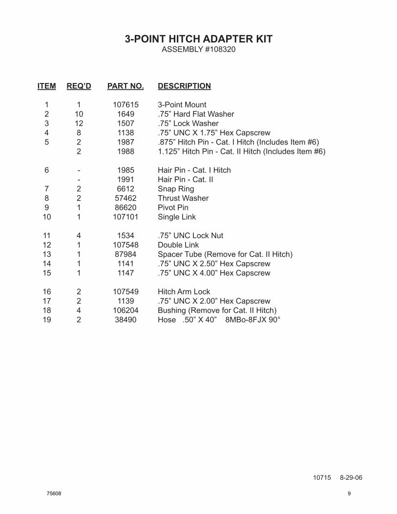
ITEM REQ’D PART NO. DESCRIPTION
1 1 107615 3-Point Mount 2 10 1649 .75” Hard Flat Washer 3 12 1507 .75” Lock Washer 4 8 1138 .75” UNC X 1.75” Hex Capscrew 5 2 1987 .875” Hitch Pin - Cat. I Hitch (Includes Item #6) 2 1988 1.125” Hitch Pin - Cat. II Hitch (Includes Item #6)
6 - 1985 Hair Pin - Cat. I Hitch - 1991 Hair Pin - Cat. II 7 2 6612 Snap Ring 8 2 57462 Thrust Washer 9 1 86620 Pivot Pin 10 1 107101 Single Link
11 4 1534 .75” UNC Lock Nut 12 1 107548 Double Link 13 1 87984 Spacer Tube (Remove for Cat. II Hitch) 14 1 1141 .75” UNC X 2.50” Hex Capscrew 15 1 1147 .75” UNC X 4.00” Hex Capscrew
16 2 107549 Hitch Arm Lock 17 2 1139 .75” UNC X 2.00” Hex Capscrew 18 4 106204 Bushing (Remove for Cat. II Hitch) 19 2 38490 Hose .50” X 40” 8MBo-8FJX 90°
ASSEMBLY #108320
75608 9
BOOM & DIPPER ASSEMBLY
10688 8-22-06
ASSEMBLY #105301
1
2
2
2
2
3
4
56
7
89
10
12
4
5
4
45
5
13814
15 16
17
18
21
22
1920
23
24
11
10 75608
BOOM & DIPPER ASSEMBLY
10689 8-22-06
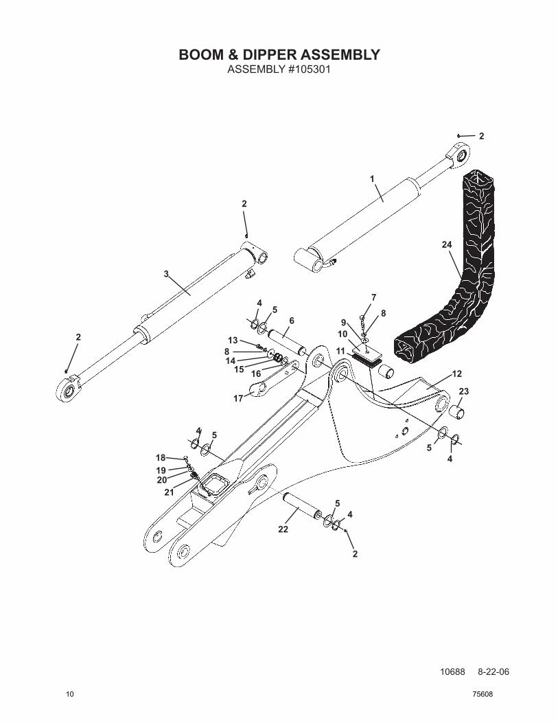
ITEM REQ’D PART NO. DESCRIPTION
1 1 105322 Boom Cylinder Assembly (Includes (1) 62523 Bushing and (2) 85772 Bushings) - 45618 Replacement Cylinder Seal Kit 2 4 6616 Grease Fitting 3 1 105314 Dipper Cylinder Assembly (Includes (2) 85772 Bushings and (1) 6615 Bearing) - 45738 Replacement Cylinder Seal Kit 4 4 1650 Snap Ring 5 Varies 6623 Thrust Washer 1.38” x .031” Varies 64724 Thrust Washer 1.38” x .090” Varies 64725 Thrust Washer 1.38” x .125”
6 1 105369 Dipper Cylinder Pin 1.38” x 6.18” 7 1 1046 .38” UNC X 1.75” Hex Capscrew 8 2 1503 .38” Lock Washer 9 1 1514 .38” Flat Washer 10 1 81881 Hose Clamp Plate 11 1 81882 Rubber Spacer
12 1 105250 Boom ( Includes (2) 81610 Bushings) 13 1 1042 .38” UNC X .75” Hex Capscrew 14 1 22298 Special Washer 15 1 105245 Compression Spring
16 1 57462 Thrust Washer 1.00” 17 1 105278 Boom Lock 18 1 1022 .31” UNC X 1.00” Hex Capscrew 19 1 1502 .31” Lock Washer 20 1 1513 .31” Flat Washer
21 1 82859 Double Hose Clamp 22 1 105372 Boom Cylinder Pin 1.38” x 7.06” 23 - 81610 Replacement Bushing (Included in Boom) 24 1 34078 Hose Sock 4” x 40”
ASSEMBLY #105301
75608 11
BOOM & DIPPER ASSEMBLY
10690 8-22-06
ASSEMBLY #105301
1
2
3
4 5
6 7
8
9
10
11
12
2
1
1
12
27
7
13
14
15
3
21
7
10
7
7
16
16
16
12 75608
BOOM & DIPPER ASSEMBLY
10691 8-22-06
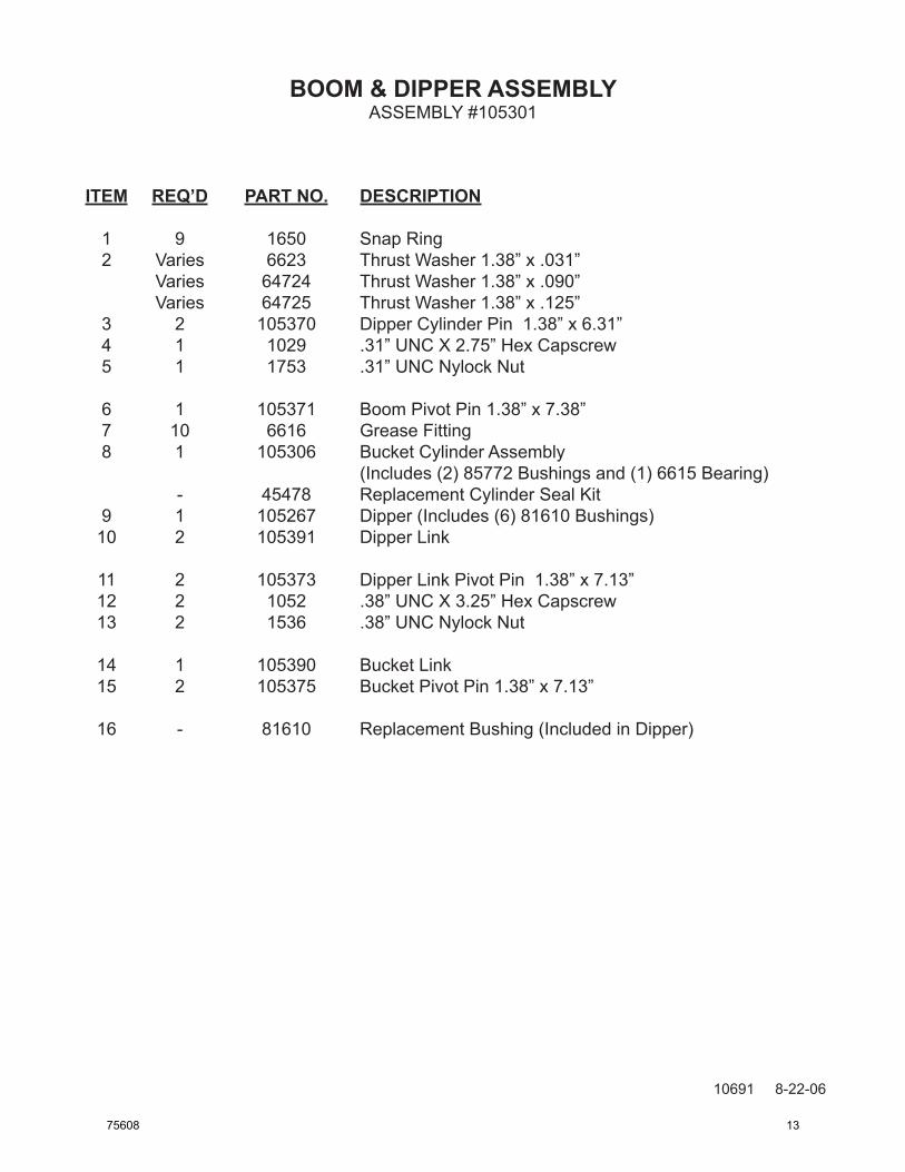
ITEM REQ’D PART NO. DESCRIPTION
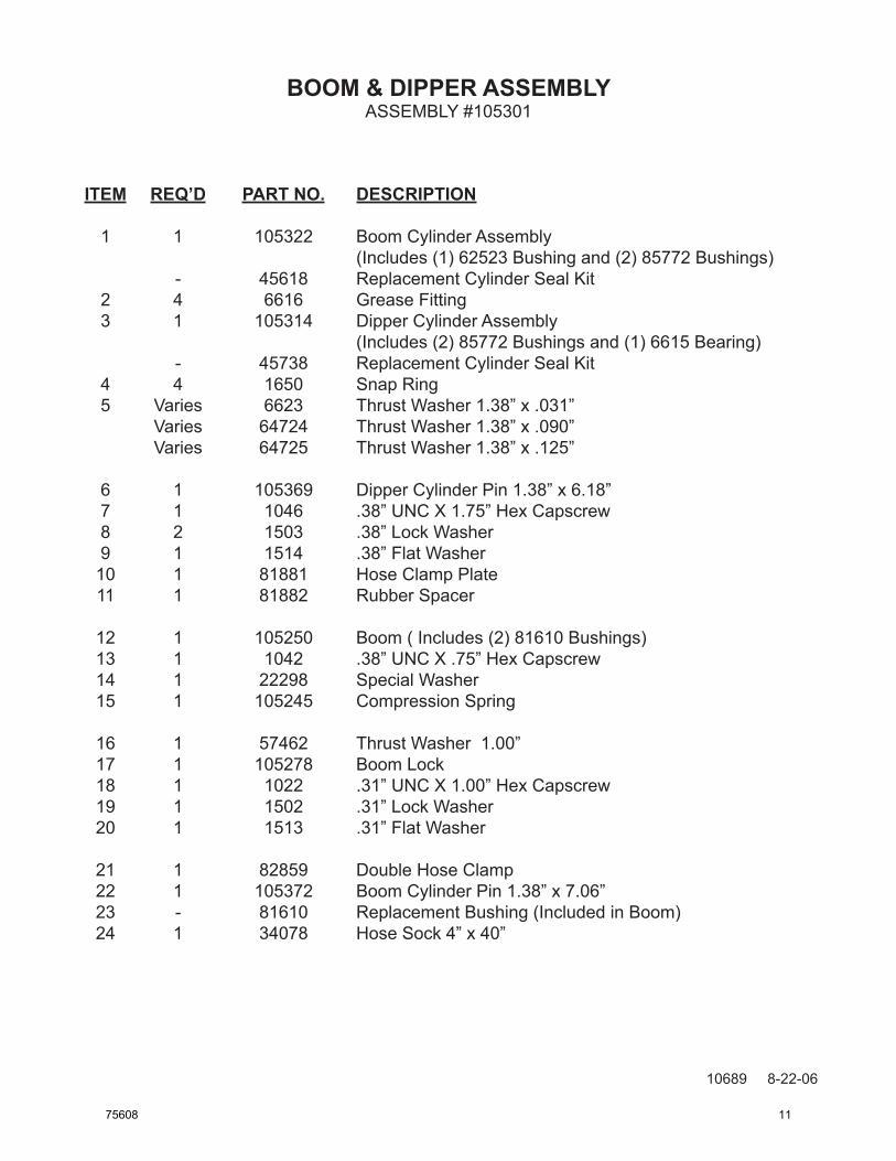
1 9 1650 Snap Ring 2 Varies 6623 Thrust Washer 1.38” x .031” Varies 64724 Thrust Washer 1.38” x .090” Varies 64725 Thrust Washer 1.38” x .125” 3 2 105370 Dipper Cylinder Pin 1.38” x 6.31” 4 1 1029 .31” UNC X 2.75” Hex Capscrew 5 1 1753 .31” UNC Nylock Nut
6 1 105371 Boom Pivot Pin 1.38” x 7.38” 7 10 6616 Grease Fitting 8 1 105306 Bucket Cylinder Assembly (Includes (2) 85772 Bushings and (1) 6615 Bearing) - 45478 Replacement Cylinder Seal Kit 9 1 105267 Dipper (Includes (6) 81610 Bushings) 10 2 105391 Dipper Link
11 2 105373 Dipper Link Pivot Pin 1.38” x 7.13” 12 2 1052 .38” UNC X 3.25” Hex Capscrew 13 2 1536 .38” UNC Nylock Nut
14 1 105390 Bucket Link 15 2 105375 Bucket Pivot Pin 1.38” x 7.13”
16 - 81610 Replacement Bushing (Included in Dipper)
ASSEMBLY #105301
75608 13
CONSOLE ASSEMBLY
10692 1-4-08-2
ASSEMBLY #105302
1
2
3
4
5
6
7
8
9
10
11
12
13
14
15
16
1718
27
20
27
19
27
318
21
2223
24
26
25
26
26
14 75608
CONSOLE ASSEMBLY
10693 1-4-08-2
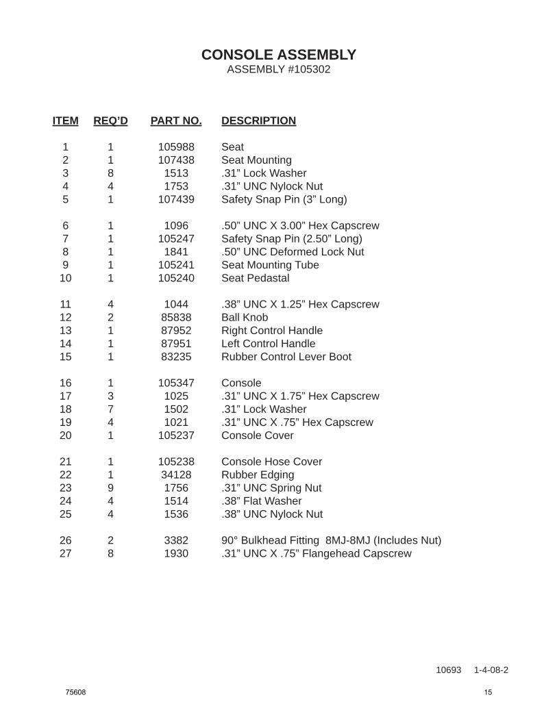
ITEM REQ’D PART NO. DESCRIPTION
1 1 105988 Seat 2 1 107438 Seat Mounting 3 8 1513 .31” Lock Washer 4 4 1753 .31” UNC Nylock Nut 5 1 107439 Safety Snap Pin (3” Long)
6 1 1096 .50” UNC X 3.00” Hex Capscrew 7 1 105247 Safety Snap Pin (2.50” Long) 8 1 1841 .50” UNC Deformed Lock Nut 9 1 105241 Seat Mounting Tube 10 1 105240 Seat Pedastal
11 4 1044 .38” UNC X 1.25” Hex Capscrew 12 2 85838 Ball Knob 13 1 87952 Right Control Handle 14 1 87951 Left Control Handle 15 1 83235 Rubber Control Lever Boot
16 1 105347 Console 17 3 1025 .31” UNC X 1.75” Hex Capscrew 18 7 1502 .31” Lock Washer 19 4 1021 .31” UNC X .75” Hex Capscrew 20 1 105237 Console Cover
21 1 105238 Console Hose Cover 22 1 34128 Rubber Edging 23 9 1756 .31” UNC Spring Nut 24 4 1514 .38” Flat Washer 25 4 1536 .38” UNC Nylock Nut
26 2 3382 90° Bulkhead Fitting 8MJ-8MJ (Includes Nut) 27 8 1930 .31” UNC X .75” Flangehead Capscrew
ASSEMBLY #105302
75608 15

THIS PAGEIS INTENTIONALLY
BLANK
16 75608
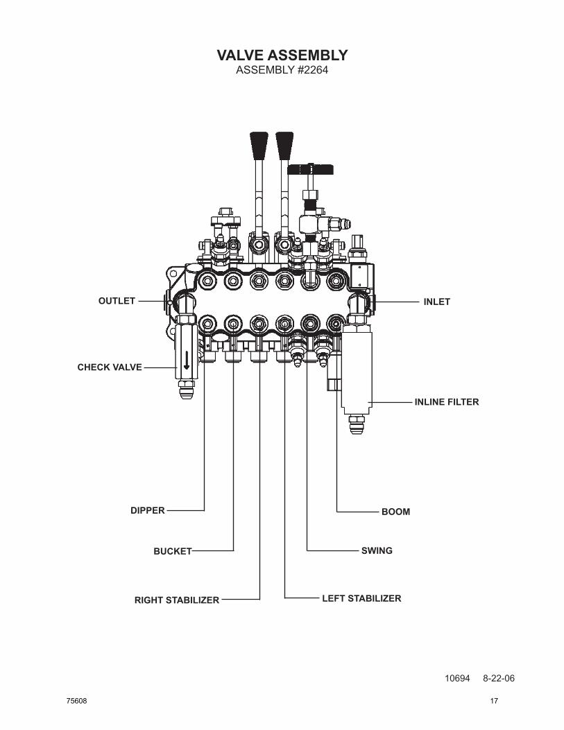
VALVE ASSEMBLY
10694 8-22-06
ASSEMBLY #2264
CHECK VALVE
inLEt
dippEr BooM
LEft StABiLizErrigHt StABiLizEr
BuCKEt Swing
inLinE fiLtEr
outLEt
75608 17
VALVE ASSEMBLY
10695 8-22-06
ASSEMBLY #2264
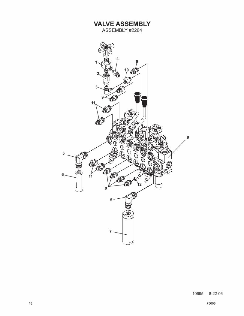
1
2
3
4
5
6
7
5
8
9
10
119
11
912
18 75608
VALVE ASSEMBLY
10696 8-22-06
ITEM REQ’D PART NO. DESCRIPTION
1 1 3185 Needle Valve 2 1 30187 Straight Connector 4FP-6FJX 3 1 3001 90° Elbow 4MP-6MJ 4 1 3137 Straight Connector 6MJ-4MP 5 2 30193 90° Elbow 8MBo-8MBo
6 1 107636 Check Valve (Hex) (Not Included in Valve Assembly #2264) 7 1 107635 Inline Filter (Round) (Not Included in Valve Assembly #2264) 8 1 105303 Valve - Bucher Monoblock (Includes Items #9 - #12) 9 7 3457 Replacement Connector 6MBo-6MJ (Included with Valve) 10 1 3461 Replacement Connector 6MBo-4FP (Included with Valve)
11 4 3269 Replacement Connector 8MBo-6MJ (Included with Valve) 12 1 45967 RestrictorOrifice(Included with Valve)
ASSEMBLY #2264
75608 19
SWING CYLINDER ASSEMBLY
10703 8-23-06
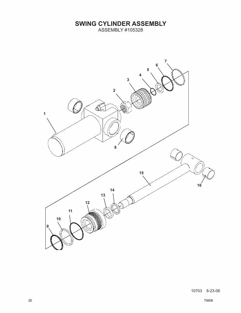
ASSEMBLY #105328
1
2
34
56
7
10
11
12
1314
15
16
9
8
20 75608
SWING CYLINDER ASSEMBLY
10704 8-23-06
ITEM REQ’D PART NO. DESCRIPTION
1 1 105329 Cylinder Tube 2 1 1483 Hex Nut (Torque to 230-325 ft. lbs.) 3 1 105333 Piston 4 1 4641* O’Ring 5 1 5421 Washer
6 1 4645* O’Ring 7 1 4644* Piston Ring 8 2 82441 Needle Bearing 9 1 4509* O’Ring 10 1 4510* Back-Up Washer
11 1 45250* O’Ring 12 1 77458 Gland 13 1 45219* Poly-Pak Seal 14 1 45389* Rod Wiper 15 1 105331 Cylinder Rod
16 2 86564* Bushing
ASSEMBLY #105328
NOTE: Seal Kit #45617 includes all parts marked with an asterisk(*). Parts are not sold separately.
75608 21
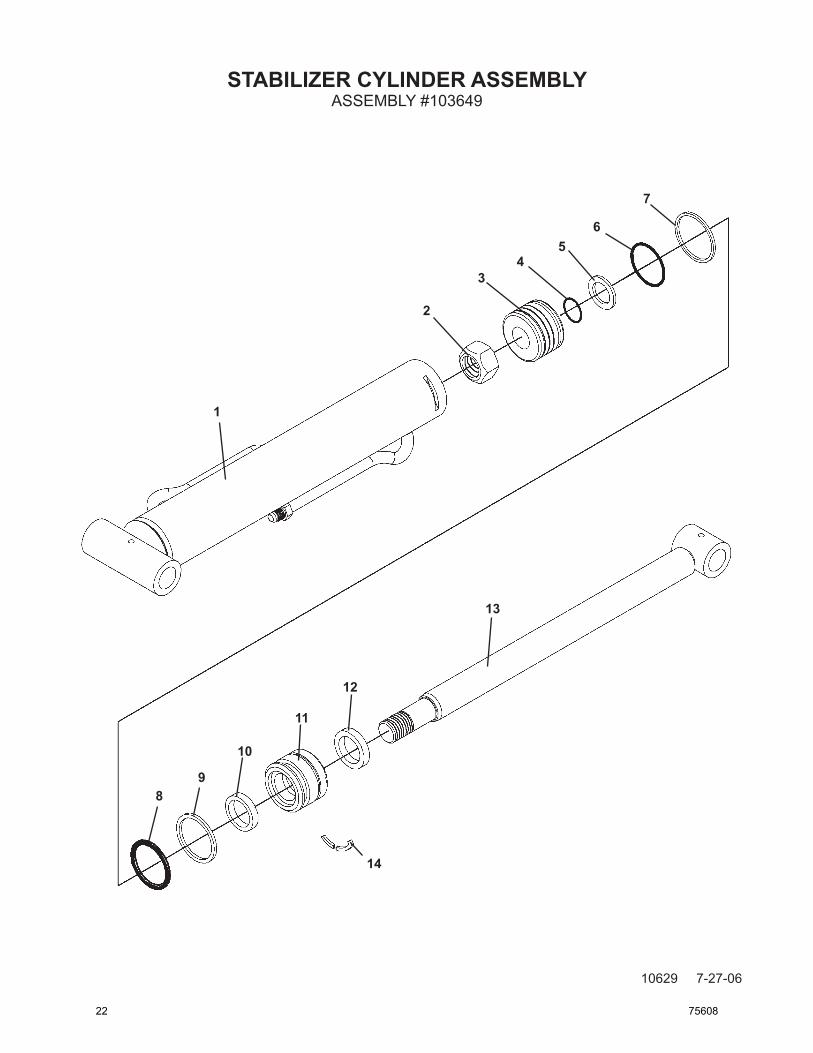
STABILIZER CYLINDER ASSEMBLY
10629 7-27-06
ASSEMBLY #103649
1
2
34
56
7
89
10
11
12
13
14
22 75608
STABILIZER CYLINDER ASSEMBLY
10630 7-27-06
ITEM REQ’D PART NO. DESCRIPTION
1 1 103651 Cylinder Tube 2 1 1483 Hex Nut (Torque to 230-325 ft. lbs.) 3 1 106372 Piston 4 1 4641* O’Ring 5 1 5421 Washer
6 1 45443* O’Ring 7 1 45701* Piston Ring 8 1 45699* O’Ring 9 1 45700* Back-Up Washer 10 1 45219* Poly-Pak Seal
11 1 86508 Gland 12 1 4974* Rod Wiper 13 1 103650 Cylinder Rod 14 1 7165* Gland Retainer Rod
ASSEMBLY #103649
NOTE: Seal Kit #45478 includes all parts marked with an asterisk(*). Parts are not sold separately.
75608 23
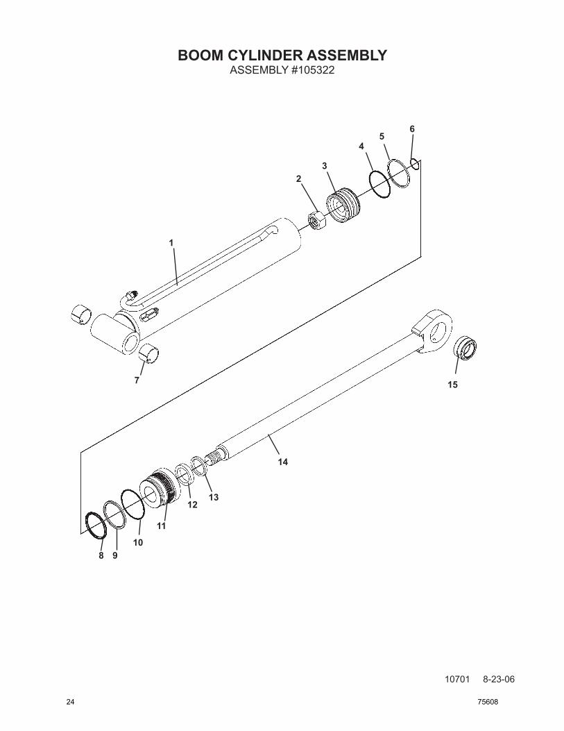
BOOM CYLINDER ASSEMBLY
10701 8-23-06
ASSEMBLY #105322
1
23
45
6
7
8 910
11
1213
14
15
24 75608
BOOM CYLINDER ASSEMBLY
10702 8-23-06
ITEM REQ’D PART NO. DESCRIPTION
1 1 105323 Cylinder Tube 2 1 1483 Hex Nut (Torque to 230-325 ft. lbs.) 3 1 105320 Piston 4 1 45250* O’Ring 5 1 45251* Piston Ring
6 1 4641* O’Ring 7 2 85772 Bushing 8 1 45557* O’Ring 9 1 45249* Back-Up Washer 10 1 4570* O’Ring
11 1 82449 Gland 12 1 45225* Poly-Pak Seal 13 1 45372* Rod Wiper 14 1 105326 Cylinder Rod 15 1 62523 Self-Aligning Bushing
ASSEMBLY #105322
NOTE: Seal Kit #45618 includes all parts marked with an asterisk(*). Parts are not sold separately.
75608 25
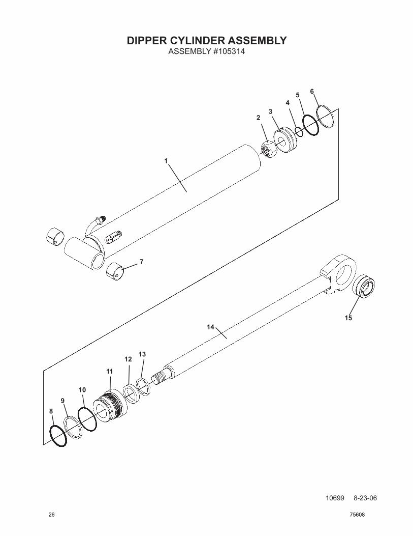
DIPPER CYLINDER ASSEMBLY
10699 8-23-06
ASSEMBLY #105314
1
23
45 6
7
89
10
11
1213
1415
26 75608
DIPPER CYLINDER ASSEMBLY
10700 8-23-06
ITEM REQ’D PART NO. DESCRIPTION
1 1 105315 Cylinder Tube 2 1 1483 Hex Nut (Torque to 230-325 ft. lbs.) 3 1 50252 Piston 4 1 4641* O’Ring 5 1 4645* O’Ring
6 1 4644* Piston Ring 7 2 85772 Bushing 8 1 4509* O’Ring 9 1 4510* Back-Up Washer 10 1 45250* O’Ring
11 1 86609 Gland 12 1 45225* Poly-Pak Seal 13 1 45372* Rod Wiper 14 1 105318 Cylinder Rod 15 1 6615 Bushing
ASSEMBLY #105314
NOTE: Seal Kit #45738 includes all parts marked with an asterisk(*). Parts are not sold separately.
75608 27
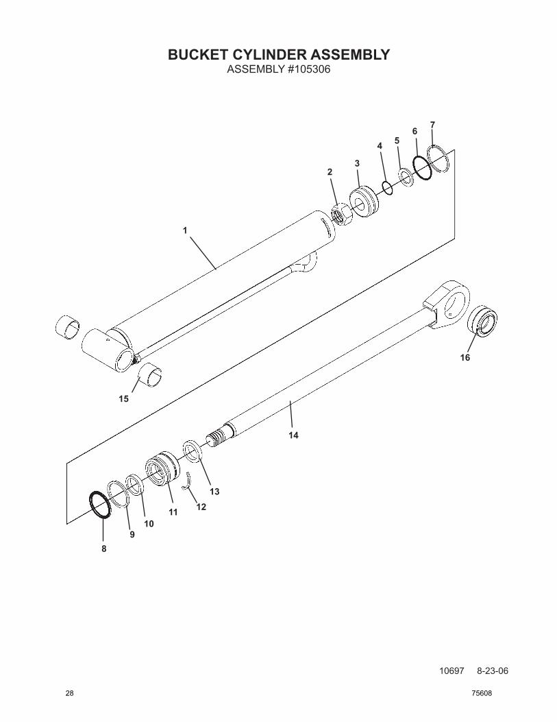
BUCKET CYLINDER ASSEMBLY
10697 8-23-06
ASSEMBLY #105306
1
23
4 56 7
89
1011 12
13
14
15
16
28 75608
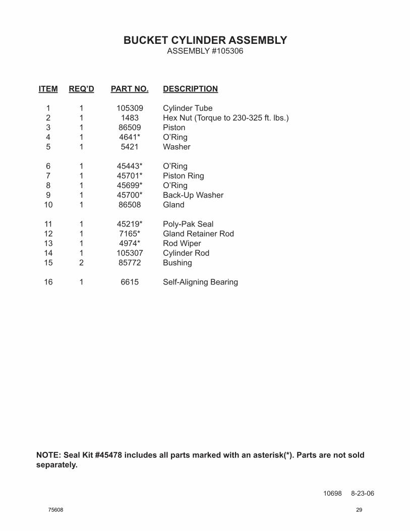
BUCKET CYLINDER ASSEMBLY
10698 8-23-06
ITEM REQ’D PART NO. DESCRIPTION
1 1 105309 Cylinder Tube 2 1 1483 Hex Nut (Torque to 230-325 ft. lbs.) 3 1 86509 Piston 4 1 4641* O’Ring 5 1 5421 Washer
6 1 45443* O’Ring 7 1 45701* Piston Ring 8 1 45699* O’Ring 9 1 45700* Back-Up Washer 10 1 86508 Gland
11 1 45219* Poly-Pak Seal 12 1 7165* Gland Retainer Rod 13 1 4974* Rod Wiper 14 1 105307 Cylinder Rod 15 2 85772 Bushing
16 1 6615 Self-Aligning Bearing
ASSEMBLY #105306
NOTE: Seal Kit #45478 includes all parts marked with an asterisk(*). Parts are not sold separately.
75608 29
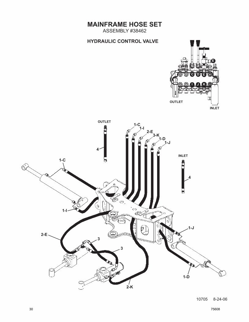
MAINFRAME HOSE SET
10705 8-24-06
ASSEMBLY #38462
INLET
c d E
kjI
OUTLET
E
1-c
1-d
2-E1-I
1-j
3-k
1-c
1-d
2-E
1-I
1-j
2-k
3
3
4
4
OUTLET
INLET
HYdRAULIc cONTROL VALVE
30 75608

MAINFRAME HOSE SET
10706 8-24-06
ITEM REQ’d PART NO. dEScRIPTION
1 4 38417 Hose Assembly .25” X 39” 6FJX 90° - 6FJX
2 2 38461 Hose Assembly .25” X 30” 6FJX 90° - 6FJX
3 2 38460 Hose Assembly .25” X 18” 6FJX 45° - 6FJX
4 2 38489 Hose Assembly .50” X 16” 8FJX - 8MBo
ASSEMBLY #38462
NOTE: Letters on the hose set diagram show the hydraulic hose routing between the backhoe control valve and the various hydraulic cylinders. Simply match the letter on the control valve port to the same letter on the hydraulic hose ends. Example: Hose labeled “C” runs from the upper right Stabilizer port on the hydraulic control valve - through the swing post (hose sock) and to the rod end fitting on the right stabilizer cylinder.
NOTE: The fittings on the hydraulic cylinders have been altered for clarity purposes. This will assist you in distinguishing between the rod end and the barrel end of the various hydraulic cylinders.
75608 31
BOOM AND DIPPER HOSE SET
10707 8-28-06
ASSEMBLY #38463
INLET
A B f
LHg
OUTLET
HYDRAULIC CONTROL VALVE
2-g
1-H1-B 3-f
3-L
2-A
2-g1-H1-B
3-f3-L
2-A
32 75608
BOOM AND DIPPER HOSE SET
10708 8-28-06
ITEM REQ’D PART NO. DESCRIPTION
1 2 38458 Hose Assembly .25” X 109” 6FJX 90° - 6FJX
2 2 38457 Hose Assembly .25” X 106” 6FJX 90° - 6FJX
3 2 38476 Hose Assembly .25” X 69” 6FJX 90° - 6FJX
ASSEMBLY #38463
NOTE: Letters on the hose set diagram show the hydraulic hose routing between the backhoe control valve and the various hydraulic cylinders. Simply match the letter on the control valve port to the same letter on the hydraulic hose ends. Example: Hose labeled “L” runs from the lower Boom port on the hydraulic control valve - through the swing post (hose sock) and to the rod end fitting on the boom cylinder.
NOTE: The fittings on the hydraulic cylinders have been altered for clarity purposes. This will assist you in distinguishing between the rod end and the barrel end of the various hydraulic cylinders.
75608 33
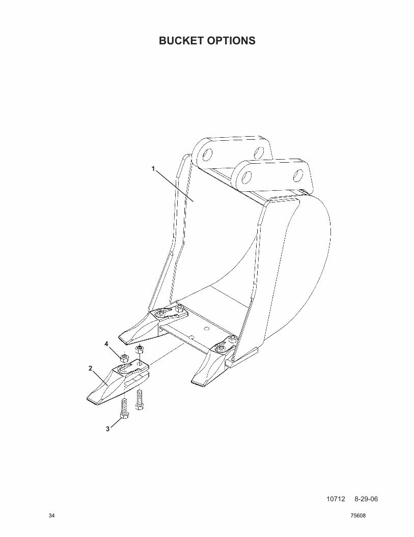
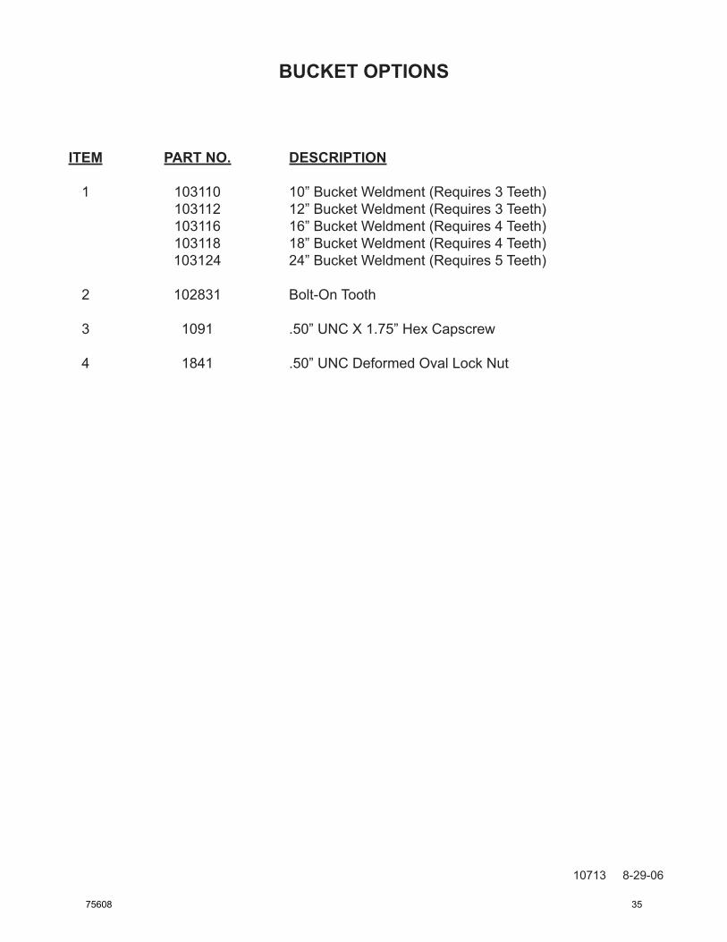
BUCKET OPTIONS
10712 8-29-06
1
4
2
3
34 75608
BUCKET OPTIONS
10713 8-29-06
ITEM PART NO. DESCRIPTION
1 103110 10” Bucket Weldment (Requires 3 Teeth) 103112 12” Bucket Weldment (Requires 3 Teeth) 103116 16” Bucket Weldment (Requires 4 Teeth) 103118 18” Bucket Weldment (Requires 4 Teeth) 103124 24” Bucket Weldment (Requires 5 Teeth)
2 102831 Bolt-On Tooth
3 1091 .50” UNC X 1.75” Hex Capscrew
4 1841 .50” UNC Deformed Oval Lock Nut
75608 35
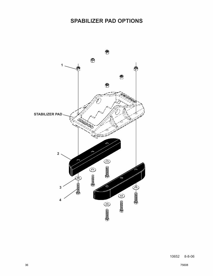
SPABILIZER PAD OPTIONS
10652 8-8-06
1
2
3
4
STABILIZER PAD
36 75608
STABILIZER PAD OPTIONS
10653 8-8-06
RUBBER PAD KIT #103676
ITEM REQ’D PART NO. DESCRIPTION
1 6 1536 .38” UNC Nylock Nut 2 2 102625 Rubber Pad 3 6 1514 .38” Flat Washer 4 6 1046 .38” UNC X 1.75” Hex Capscrew
75608 37
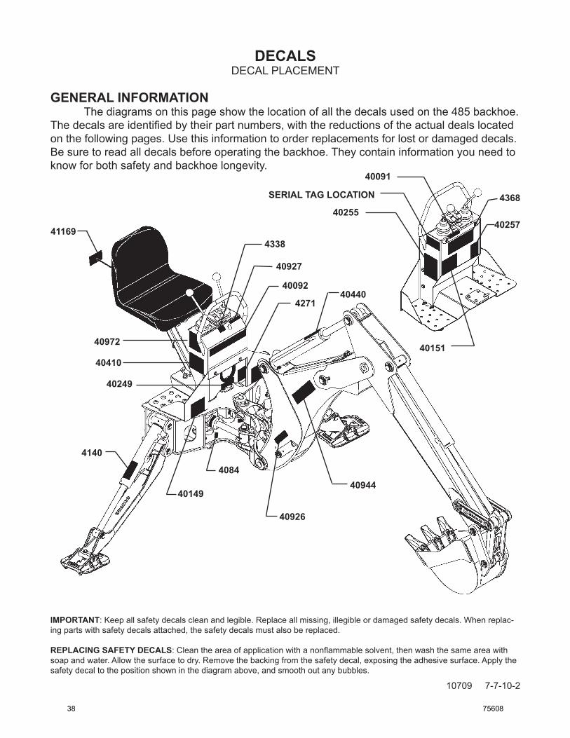
DECALS
10709 7-7-10-2
DECAL PLACEMENT
GENERAL INFORMATION The diagrams on this page show the location of all the decals used on the 485 backhoe. The decals are identified by their part numbers, with the reductions of the actual deals located on the following pages. Use this information to order replacements for lost or damaged decals. Be sure to read all decals before operating the backhoe. They contain information you need to know for both safety and backhoe longevity.
40091
40092
40149
40151
40249
4025540257
40440
408440944
40926
40927
4140
4271
4338
4368SERIAL TAG LOCATION
IMPORTANT: Keep all safety decals clean and legible. Replace all missing, illegible or damaged safety decals. When replac-ing parts with safety decals attached, the safety decals must also be replaced.
REPLACING SAFETY DECALS: Clean the area of application with a nonflammable solvent, then wash the same area with soap and water. Allow the surface to dry. Remove the backing from the safety decal, exposing the adhesive surface. Apply the safety decal to the position shown in the diagram above, and smooth out any bubbles.
40972
41169
40410
38 75608
DECALS
10710 7-6-10-2
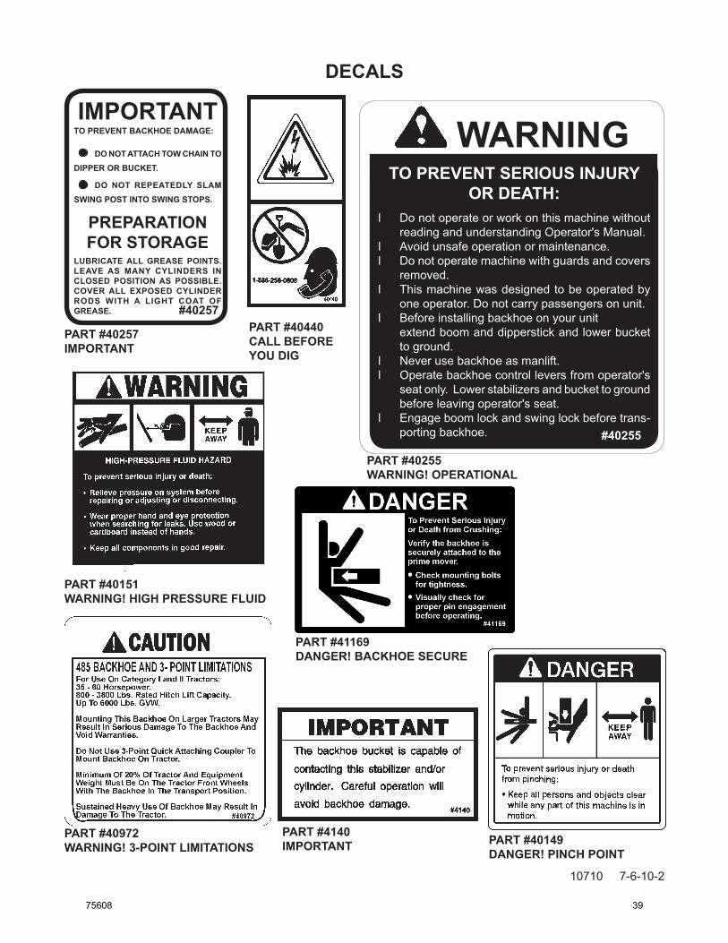
IMPORTANTTO PREVENT BACKHOE DAMAGE:
DO NOT ATTACH TOW CHAIN TO DIPPER OR BUCKET.
DO NOT REPEATEDLY SLAM SWING POST INTO SWING STOPS.
PREPARATIONFOR STORAGE
LUBRICATE ALL GREASE POINTS. LEAVE AS MANY CYLINDERS IN CLOSED POSITION AS POSSIBLE. COVER ALL EXPOSED CYLINDER RODS WITH A LIGHT COAT OF GREASE. #40257
PART #40257IMPORTANT
PART #40440CALL BEFORE YOU DIG
PART #4140IMPORTANT
PART #40151WARNING! HIGH PRESSURE FLUID
WARNINGTO PREVENT SERIOUS INJURY
OR DEATH:l Do not operate or work on this machine without
reading and understanding Operator's Manual.l Avoid unsafe operation or maintenance.l Do not operate machine with guards and covers
removed.l This machine was designed to be operated by
one operator. Do not carry passengers on unit.l Before installing backhoe on your unit extend boom and dipperstick and lower bucket
to ground.l Never use backhoe as manlift.l Operate backhoe control levers from operator's
seat only. Lower stabilizers and bucket to ground before leaving operator's seat.
l Engage boom lock and swing lock before trans-porting backhoe. #40255
PART #40255WARNING! OPERATIONAL
PART #40149DANGER! PINCH POINT
PART #40972WARNING! 3-POINT LIMITATIONS
PART #41169DANGER! BACKHOE SECURE
75608 39
DECALS
10711 8-29-06
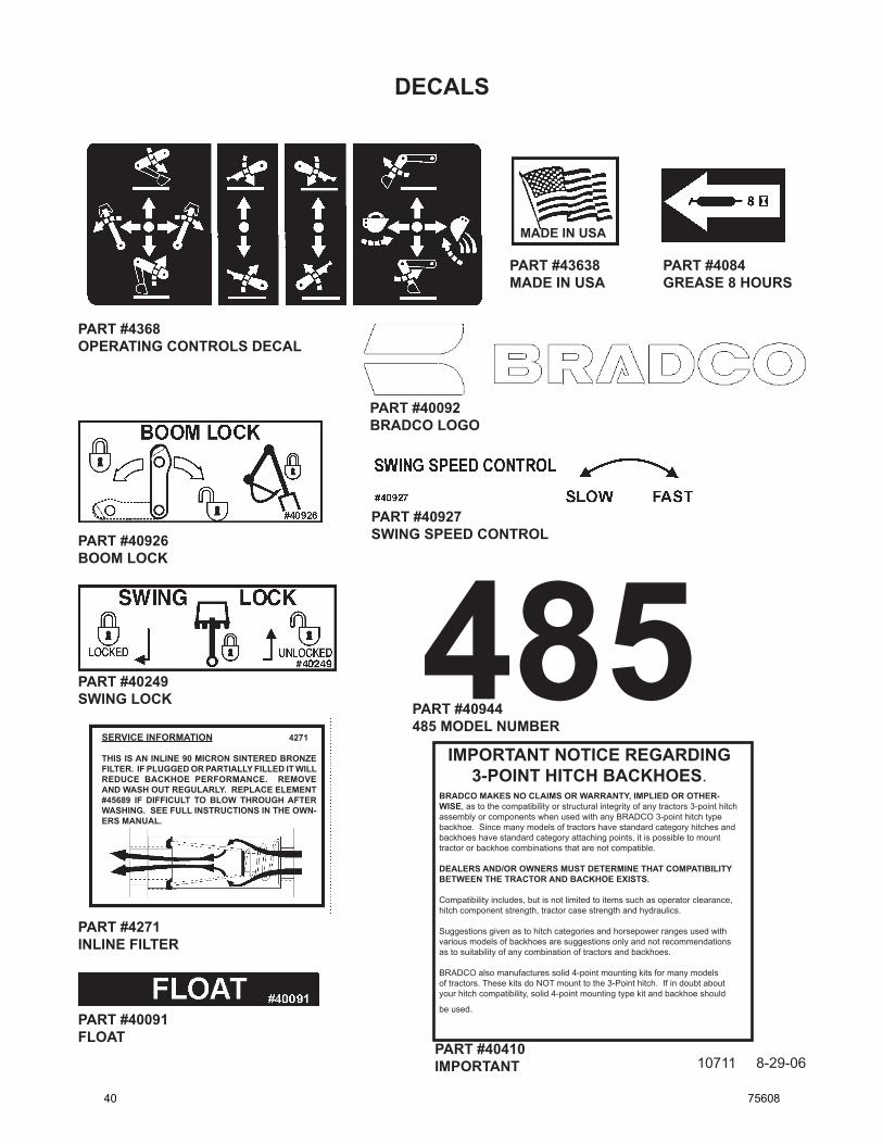
MADE IN USA
SERVICE INFORMATION 4271
THIS IS AN INLINE 90 MICRON SINTERED BRONZE FILTER. IF PLUGGED OR PARTIALLY FILLED IT WILL REDUCE BACKHOE PERFORMANCE. REMOVE AND WASH OUT REGULARLY. REPLACE ELEMENT #45689 IF DIFFICULT TO BLOW THROUGH AFTER WASHING. SEE FULL INSTRUCTIONS IN THE OWN-ERS MANUAL.
485
PART #4368OPERATING CONTROLS DECAL
PART #40926BOOM LOCK
PART #40927SWING SPEED CONTROL
PART #40091FLOAT
PART #4084GREASE 8 HOURS
PART #43638MADE IN USA
PART #40249SWING LOCK PART #40944
485 MODEL NUMBER
PART #40092BRADCO LOGO
PART #4271INLINE FILTER
IMPORTANT NOTICE REGARDING 3-POINT HITCH BACKHOES.
BRADCO MAKES NO CLAIMS OR WARRANTY, IMPLIED OR OTHER-WISE, as to the compatibility or structural integrity of any tractors 3-point hitch assembly or components when used with any BRADCO 3-point hitch type backhoe. Since many models of tractors have standard category hitches and backhoes have standard category attaching points, it is possible to mount tractor or backhoe combinations that are not compatible.
DEALERS AND/OR OWNERS MUST DETERMINE THAT COMPATIBILITY BETWEEN THE TRACTOR AND BACKHOE EXISTS.
Compatibility includes, but is not limited to items such as operator clearance, hitch component strength, tractor case strength and hydraulics.
Suggestions given as to hitch categories and horsepower ranges used with various models of backhoes are suggestions only and not recommendations as to suitability of any combination of tractors and backhoes.
BRADCO also manufactures solid 4-point mounting kits for many models of tractors. These kits do NOT mount to the 3-Point hitch. If in doubt about your hitch compatibility, solid 4-point mounting type kit and backhoe should
be used.
PART #40410IMPORTANT
40 75608