Embed Size (px)
DESCRIPTION
submarine
Citation preview

US Navy Fleet Submarine Manual
NavPers 16160
Produced for ComSubLant by
Standards and Curriculum Division
Training, Bureau of Naval Personnel
June 1946
RESTRICTED
CONTENTS
SUBMARINE HISTORY AND DEVELOPMENT
CHAPTER 1. DEVELOPMENT OF THE SUBMARINE
A. Early Underwater Devices
B. Early Submarines
C. Modern Submarines
D. General Data
SUBMARINE CONSTRUCTION
CHAPTER 2. DEFINITIONS AND PHRASEOLOGY
A. General Definitions
B. Standard Phraseology
C. Common Abbreviations
CHAPTER 3.
COMPARTMENTATION AND EXTERIOR
INSTALLATIONS
A. Compartmentation
B. Exterior Installations
CHAPTER. 4.
TANK ARRANGEMENTS
A. Tanks
B. Water Ballast Tanks
C. Main Ballast Tanks
D. Variable Ballast Tanks
E. Special Ballast Tanks
F. Fuel Ballast Tanks
G. Additional Tanks
CHAPTER 5.
BUOYANCY AND STABILITY
A. Buoyancy
B. Stability
CHAPTER 6. ENGINEERING PLANT
A. Type of Drive
B. Engines
C. Electrical Equipment
D. Auxiliary Equipment
E. Circuits and Switchboards
CHAPTER 7.
VENTILATION SYSTEM
A. Ventilation Arrangement
B. Air Purification
C. Valves
CHAPTER 8.
REFRIGERATING AND AIR-CONDITIONING
SYSTEMS
A. Principles of Mechanical Refrigeration
B. Mechanical Details of Air-Conditioning
System
CHAPTER 9.
WATER SYSTEM
A. Introduction
B. Fresh Water System
C. Battery Water System
D. Galley Equipment
E. Plumbing
F. Heads
G. Distillation
CHAPTER 10.
TRIM AND DRAIN SYSTEMS
A. Trim System
B. Trim Pump
C. Manifolds
D. Valves
E. Drain System
F. Drain Pump
G. Valves and Fittings

CHAPTER 11. AIR SYSTEMS
A. General Data
B. Types and Relationships of Air Systems
C. High-Pressure Air and Torpedo Impulse Air
Systems
D. The 600-Pound Main Ballast Tank Blowing
System
E. The 225-Pound Air System (Ship's Service
Air)
F. The 10-Pound Main Ballast Tank Blowing
System
G. Salvage Air System
CHAPTER 12.
MAIN HYDRAULIC SYSTEM
A. Introduction
B. Power Generating System
C. Operations
D. Forward and After Service Lines
E. Emergency Steering and Plane Tilting Systems
CHAPTER 13.
THE STEERING SYSTEM
A. Introduction
B. Description
C. Operations
CHAPTER 14.
BOW AND STERN PLANES SYSTEMS
A. Introduction
B. Bow and Stern Plane Diving Gear
C. Operations
CHAPTER 15.
ANCHOR HANDLING GEAR AND
CAPSTANS
A. Anchor Handling Gear
B. Capstans
C. Operations
CHAPTER 16.
FUEL AND LUBRICATING OIL SYSTEMS
A. Fuel Oil System
B. Reserve Fuel Oil Tanks
C. Lubricating Oil System

SUBMARINE OPERATIONS
CHAPTER 17. GENERAL SURFACE OPERATIONS
A. Officer of the Deck
B. Ship Handling
C. Standard Phraseology
CHAPTER 18.
GENERAL DIVING OPERATIONS
A. Submerging
B. Submerged Operation
C. Surfacing
D. Phraseology
CHAPTER 19.
COMPENSATION
A. General
B. Compensation by Moments
C. The Compensation Curve
D. Compensation by Percentage
CHAPTER 20.
PATROL ROUTINE
A. Introduction
B. Duties of Watch Standers
C. Diving and Surfacing Procedures
D. Approach Officer
E. Torpedo Rooms
F. Standard Phraseology
SUBMARINE TRAINING
CHAPTER 21. SUBMARINE TRAINING DEVICES
A. General
B. The Attack Teacher
C. The Diving Trainer.
D. The Torpedo Tube Trainer
APPENDIX.
Illustrations Removed due to Blurred Quality
(Ed.)

1
DEVELOPMENT OF THE SUBMARINE
A. EARLY UNDERWATER DEVICES
1A1. Early Greek devices. The
submarine first became a major factor
in naval warfare during World War I,
when Germany demonstrated its full
potentialities. However, its advent at
that time, marked by wholesale
sinkings of Allied shipping, was in
reality the culmination of a long
process of development.
Ancient history includes occasional
records of attempts at underwater
operations in warfare. The Athenians
are said to have used divers to clear the
entrance of the harbor of Syracuse
during the siege of that city; during his
operations against Tyre, Alexander the
Great ordered divers to impede or
destroy any submarine defenses the city
might undertake to build. But in none
of these records is there a direct
reference to the use of submersible
apparatus of any kind. There is,
however, a legend that Alexander the
Great himself made a descent into the
sea in a device which kept its occupants
dry and admitted light.
In the Middle Ages, the Arabian
historian Boha-Eddin reports that a
diver using submersible apparatus
succeeded in gaining entrance into
Ptolemais (Acre) during the siege of
that city in A.D. 1150. And in 1538, a
diving bell was built and tested at
Toledo, Spain. Although it attracted the
attention of the Emperor Charles V, the
device was never further developed and
passed quickly into oblivion.
1A2. Bourne's idea. Not until 1580
sponsored by one Magnus Pegelius was
launched in 1605. But the designers
made one serious oversight. They failed
to consider the tenacity of underwater
mud, and the craft was buried at the
bottom of a river during initial
underwater trials.
1A3. Van Drebel's submersible. It is to
Cornelius Van Drebel, a Dutch
physician, that credit is usually given for
building the first submarine. To him is
conceded the honor of successfully
maneuvering his craft, during repeated
trials in the Thames River, at depths of
12 and 15 feet beneath the surface.
Van Drebel's craft resembled those of
Bourne and Pegelius in that its outer hull
consisted of greased leather over a
wooden framework. Oars, extending
through the sides and sealed with tight-
fitting leather flaps, provided propulsion
either on the surface or when submerged.
Van Drebel built his first boat in 1620
and followed it later with two others both
larger but embodying the same
principles. It is reported that after
repeated tests, James I took a trip in one
of the larger models and demonstrated its
safety. But despite this evidence of royal
favor, the craft failed to arouse the
interest of the navy in an age when all
conception of the possibilities of
submarine warfare was still far in the
future.
1A4. Eighteenth century plans. Submarine boats seem to have been
numerous in the early years of the 18th
century. By 1727 no fewer than 14 types

does any record appear of a craft
designed to be navigated under water.
In that year, William Bourne, a British
naval officer, made designs of a
completely enclosed boat which could
be submerged and rowed under the
surface. The device consisted of a
wooden framework covered with
waterproofed leather. It was to be
submerged by reducing its volume as a
result of contracting the sides through
the use of hand vises. Although Bourne
never built this boat, a similar
construction
had been patented in England alone.
An unidentified inventor whose work is
described in the Gentleman's Magazine
for 1747 introduced an ingenious device
for submerging and surfacing his
submarine. His craft was to have had a
number of goatskins built into the hull,
each of which was to be connected to an
aperture in the bottom. He planned to
submerge the vessel by filling the skins
with water, and to bring it to the
surface again by forcing the water out
of the skins with a "twisting rod." This
seems to have been the first approach to
the modern ballast tank. By that time,
ideas were plentiful, some of them
fanciful and grotesque, but some
containing elements capable of
practical
application. Lack of full understanding of
the physical and mechanical principles
involved, coupled with the well-nigh
universal conviction that underwater
navigation was impossible and of no
practical value, postponed for more than
another hundred years the attempt to
utilize a submarine in warfare.
B. EARLY SUBMARINES
1B1. David Bushnell's Turtle. During
the American Revolutionary War, a
submarine was first used as an
offensive weapon in naval warfare. The
Turtle, a one-man submersible invented
by David Bushnell and hand-operated
by a screw propeller, attempted to sink
a British man-of-war in New York
Harbor. The plan was to attach a charge
of gunpowder to the ship's bottom
with screws and explode it with a time
fuse. After repeated failures to force the
screws through the copper sheathing on
the hull of the HMS Eagle, the submarine
gave up, released the charge, and
withdrew. The powder exploded without
result, except that the Eagle at once
decided to shift to a berth farther out to
sea.
1B2. Fulton's Nautilus. Although his
name is most often associated with the
invention of the steamboat, Robert
Fulton experimented with submarines
at least a decade before he sailed the
Clermont up the Hudson. His Nautilus
development of the craft, even though his
model displayed some of the best
features of any submarine up to that time.
1B3, The Confederate "Davids". Development of the submarine boat was

was built of steel in the shape of an
elongated oval, and was somewhat
similar in structure to today's
submarine. A sail was employed for
surface propulsion and a hand-driven
propeller drove the boat
held back during all of this period by lack
of any adequate means of propulsion.
Nevertheless, inventors continued
resolutely with
when submerged. A modified form of
conning tower was equipped with a
porthole for observation, since the
periscope had not yet been invented. In
1801, Fulton tried to interest France,
Britain, and America in his idea, but no
nation ventured to sponsor the
experiments upon small, hand-propelled
submersibles carrying a crew of not more
than six or eight men. On 17 February
1864, a Confederate vessel of this type
sank a Federal corvette that was blocking
Charleston harbor. This first recorded
instance of a
3
Figure 1-3. The HUNTLEY, one of numerous "Davids" constructed during the War
Between the States.
submarine sinking a warship was
accomplished by a torpedo suspended
ahead of the bow of the Huntley as she
rammed the Housatonic.
1B4. Garrett's steam propulsion. Interest in the improvement of the
submarine was active during the period
of the War Between the States, but the
problem of a suitable means of
propulsion continued to limit progress.
Steam was tried and finally in 1880 an
English clergyman, the Rev. Mr.
Garrett, successfully operated a
submarine with steam from a coal-fired
could submerge to a depth of 50 feet, was
fitted with one of the first practical
torpedo tubes.
1B5. Electric propulsion. Meanwhile,
electric propulsion machinery had proved
its utility in many fields, and in 1886, an
all-electric submarine was built by two
Englishmen, Campbell and Ash. Their
boat was propelled at a surface speed of 6
knots by two 50-horsepower electric
motors operated from a 100-cell storage
battery. However, this craft suffered one
major handicap; its batteries had to be
recharged and overhauled at such short

boiler which featured a retractable
smokestack. During the same period, a
Swedish gun designer, Nordenfelt, also
constructed a submarine using steam
and driven by twin screws. His craft,
which
intervals that its effective range never
exceeded 80 miles.
C. MODERN SUBMARINES
1C1. Holland's Plunger, Antedating
the efforts of Nordenfelt were the
experiments of J. P. Holland of New
Jersey, who launched his first boat in
1875. Although his early
models embodied features that were
discontinued as development progressed,
many of his initial ideas, perfected in
practice, are in use today. Outstanding in
importance was
4
the principle of submergence by water
ballast, and the use of horizontal
rudders to dive the boat. However, not
until 1895, did Holland, in competition
with Nordenfelt, finally receive an
order for a submarine from the United
States Government. The vessel was
propelled by steam on the surface and
by electricity when submerged. This
craft was named the Plunger. The
original craft was redesigned frequently
during construction and finally
abandoned altogether in favor of a
newer model already building in the
Holland shipyard. This was Holland's
ninth submersible, but it was the first to
be delivered to the United States
Government. It was delivered in 1900,
and was the basic design of all British
submarines to follow.
1C2. Lake's Submarines. Simon Lake,
who began building submarines in
1894, designed them primarily with
peacetime uses in mind.
His vessels could travel about on the sea
bottom, and had an air lock which
permitted a passenger in a diving helmet
to emerge from the hull to walk about
and explore. In fact, Lake used his
vessels extensively in commercial
salvaging operations. His first model, the
Argonaut, Jr. was solely an experimental
one. It was built of two layers of yellow
pine with a sheet of canvas between
them, and was operated by hand.
It was followed in 1897 by the Argonaut,
a cigar-shaped hull 36 feet long and
powered by a 30-horsepower gasoline
engine. This craft could submerge to the
bottom of a lake or river and roll along at
bottom on three wheels; or, for
navigating. The wheels could be raised
and carried in packets in the keel. In
1898 the Argonaut traveled under its own
power through heavy November storms
from Norfolk to New York, and was thus
the first

Figure 1-4. The ARGONAUT JR.
5
submarine to navigate extensively in
the open sea. In 1906 Lake built the
Protector and sold it to Russia. After it
had successfully passed various severe
tests there, Lake built a number of
submersibles on contract for the
Russian Government.
1C3. Conclusion. Thus the
fundamental principles of construction
and operation of submarine boats had
been determined and demonstrated
before the outbreak of World War I. By
that time, too, internal combustion
engines, both gasoline and Diesel, were
available for use as practical power
plants.
The invention of the periscope had
materially increased the practical
feasibility of underwater navigation. And
the primary weapon of the submarine, the
torpedo, had been perfected for use.
Thus, the preliminary development of the
submarine was finished, and the vessel
was ready to take its place as a major
factor in naval strategy. In place of the
tiny, one-man contraptions that first
dared to venture beneath the surface had
come effective weapons, only a little
short of the powerful, 70-man, fleet-type
submarines that range the seas today.
D. GENERAL DATA
1D1. Type of Construction. When the
submarine rests on the surface, so little
of it is seen above the water that it has
the appearance of being longer and
more slender than
it really is. Actually, the modern fleet
type submarine is approximately 312 foot
long with a superstructure deck tapering
almost to a point, both fore and aft, from
its greatest width of approximately 16

feet amidship.
Figure 1-5. USS O-7 (1918)
6
Figure 1-6. USS R-6 (1919).

Figure 1-7. USS S-17 (1921)
7
Figure 1-8. USS S-46 (1925).

Figure 1-9. USS NARWHAL (1930).
8
Figure 1-10. USS BLACKFIN (1944).
Beneath the superstructure deck is the
all-welded hull; actually it is two hulls,
for the fleet-type submarine is a
double-hull vessel. To understand the
construction of a submarine, one must
first appreciate the conditions under
which the vessel operates below the
surface. This means that the submarine
must at all times be watertight,
pressure. The fabrication of these
containers into the hull of the vessel is
illustrated in Figure 1-11.
Pressure vessels, while capable of
withstanding great pressure, do not in
themselves possess great rigidity. Being
subject to mechanical action (leverage),
they must be secured to each other by

otherwise self-destruction would result.
The construction of the submarine,
therefore, is on the basis of the
fabrication of a series of watertight
containers into one large watertight
cylinder by means of watertight joints.
However, since the submarine must
operate at times at great depths, these
watertight containers must be strong
enough to withstand the pressure head
of sea water at that depth. Therefore,
the watertight containers must be
pressure vessels, that is, watertight
containers or cylinders capable of
withstanding great
one common strength member (the keel),
as well as by watertight connections
(bulkheads). The submarine with its keel,
pressure hull, and watertight bulkheads is
shown in Figure 1-12.
In the double-hull type of submarine, the
pressure hull is inside the outer hull;
between the two hulls are the water and
the fuel oil tanks. The double-hull
construction extends from the after
bulkhead of the forward torpedo room to
the forward bulkhead of the after torpedo
room. The pressure hull,
9
Figure 1-11. Type of construction, showing arrangement of compartments, without
the superstructure or tanks.
or inner hull, extends from the forward
bulkhead of the forward trim tank to the
after bulkhead of the after trim tank.
Above the hull is built a non-watertight
superstructure which forms the main
deck, for use when surfaced.
A gun, usually a 5"/25, wet type, is
mounted topside. The space below the
deck is used as locker space for stowing
anchor gear, lines, and other gear that
cannot be damaged by water. Ready
ammunition in boxes and the ship's
boat are also kept here.
The deck is perforated on either side with
circular holes among the entire length to
prevent air pockets from forming within
the superstructure when it becomes
flooded. A watertight tower, know as the
conning tower, extends upward through
the superstructure amidships. The top of
the conning tower is used as a bridge
when on the surface, but when
submerged, the control of the boat is
maintained either from the conning tower
or from a compartment directly below it,
known as the control room. Periscopes

Figure 1-12. Type of construction, showing the general arrangement of the
superstructure.
10
operated from the conning tower extend
above the bridge and are used for
making observations when submerged.
1D2. Size. In the accompanying table
are shown dimensional data of the fleet
type submarine.
1D3. Depth and pressure. The modern
fleet
Individual compartments are air tested
for tightness only to a pressure of 15 psi.
Watertight bulkheads are designed
structurally and strengthened through
reinforcements to withstand the pressure
at the previously mentioned test depths.
The total pressure that the hull must
Displacement (designed) 1,523 tons
Displacement (surface) 1,816 tons (diving
trim
Length (over-all) 311'-9"
Breadth (extreme) 27"-4"
Mean draft (surface) 15'-3" (diving trim)
Number of frames 139
Frame spacing (except 35 to 62 and 69 to 105
spacing 30") 24" center to center
Freeboard at stern 3'-11"
Freeboard at bow 12'-5"
Diameter pressure hull (max.) 16'-0 3/8"
Distance from keel to centerline of hull 12'-0"
Floodable space
Forward torpedo room 4,481 cu. ft.
Forward battery compartment 4,056 cu. ft.

Control room 4,653 cu. ft.
Conning tower 760 cu. ft.
After battery compartment 5,821 cu. ft.
Forward engine room 4,535 cu. ft.
After engine room 4,277 cu. ft.
Maneuvering room 3,410 cu. ft.
After torpedo room 3,455 cu. ft.
Total floodable space 35,448 cu. ft.
Type submarine is built to withstand
the pressure of a head of sea water,
consistent with requirements as shown
by battle experience and with the
Bureau of Ships specifications. The
pressure is measured in actual
submergence tests from the surface of
the water to the axis of the vessel
through its pressure hull.
withstand is actually the differential
pressure between the interior hull
pressure and the external head of water at
a given depth.
1D4. Main propulsion, speed and
cruising radius. The average fleet type
submarine is driven by four main
propulsion diesel engines, each capable
of producing 1600 hp.
11
Figure 1-13. Torpedo tubes.

Figure 1-14. Deck gun, 5"/25.
12
Figure 1-15. Antiaircraft gun, 40 mm.
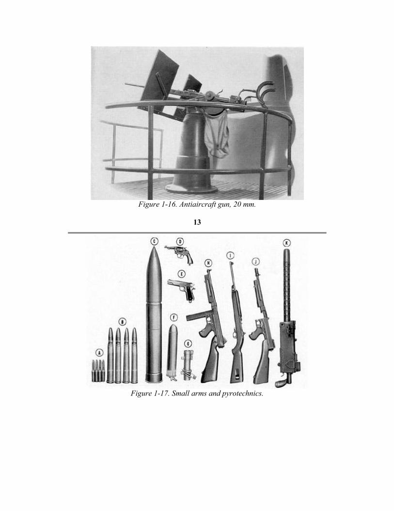
Figure 1-16. Antiaircraft gun, 20 mm.
13
Figure 1-17. Small arms and pyrotechnics.

Figure 1-18. Conning tower, looking aft.
14
Figure 1-19. Lower portion of a modern periscope.
15
The four main generators each produce
1100 kw. There are four main motors,
driven by the generators or batteries,
The rollers aft of the tubes and the racks
farther aft (not shown in the illustration)
are used for torpedo reload. The tubes

each producing about 1375 hp. The two
reduction gears are of the herringbone,
2-pinion type and produce about 2750
hp at each shaft. The auxiliary engine is
rated at 450 hp and drives a 300-kw
generator.
The average fleet type submarine is
capable of a speed of about 21 knots
when operating on the surface and
approximately 10 knots when
submerged. This submarine has a
cruising range in excess of 12,000
miles.
1D5. Ship's complement and ship's
armament. a. Ship's complement. The
personnel aboard the fleet type
submarine range in number from 66 to
78. Officers number from 6 to 8, and
men from 60 to 70.
b. Ship's armament. Torpedo tubes
(figure 1-13) are the main offensive and
defensive armament of the submarine.
A total of 10 21-in. tubes are carried,
six forward and four aft. Those shown
in the illustration are No. 1 and No. 2.
Located in pairs below tubes No. 1 and
No. 2 are Nos. 3 and 4, and Nos. 5 and
6. The upper half of the No. 3 tube is
visible in the lower right corner of the
illustration.
Immediately above tubes No. 1 and No.
2 is the torpedo tube blow and vent
manifold used for blowing or venting
the tubes, WRT tank, and the trim tank.
(See Figure 1-13.)
can be fired electrically or by hand when
surfaced or submerged. The condition of
the tube is indicated by the torpedo ready
lights, shown to the left of the No. 2 tube.
The 5"/25 deck gun (Figure 1-14) is a
dual purpose gun. It is so mounted as to
be used effectively against surface craft
and aircraft. Two guns may be carried: if
one gun is carried it is located abaft of
the conning tower.
The 40-mm antiaircraft gun (Bofors),
shown in Figure 1-15, is mounted
forward of the conning tower. It is
principally an antiaircraft weapon, but
may be used against surface craft. It is a
rapid fire, recoil type of gun. In some
instances it is being replaced by a 37-mm
gun. The 40-mm gun sometimes replaces
two 20-mm guns.
The 20-mm antiaircraft gun (Figure 1-
16), sometimes referred to as the
Oerlikon gun, is located either forward or
aft of the conning tower on the bridge
deck. It is a rapid fire, recoil type of gun.
In some instances the single mount has
been replaced by twin mounts. Four 20-
mm guns are carried by the fleet type
submarine.
In addition to the armament described
above, the fleet type submarine carries
other small arms and pyrotechnics
(Figure 1-17). Chief among these are two
30-caliber and four 50-caliber Browning
machine guns, and one 45-caliber
Thompson submachine gun.
16

2
DEFINITIONS AND PHRASEOLOGY
A. GENERAL DEFINITIONS
Introduction. The definitions contained
in this chapter are exact meanings of the
terms commonly used in reference to the
modern submarine and its operation.
These terms and explanations represent
accepted interpretations and provide an
understanding of the functions of the
equipment.
2Al. Surface condition. A submarine is
in surface condition when she has
sufficient positive buoyancy to permit
running on her main engines.
2A2. Diving trim. The term diving trim
designates that condition of a submarine
when it is so compensated that
completing the flooding of the main
ballast, safety, and bow buoyancy tanks
will cause the vessel to submerge with
neutral buoyancy and zero fore-and-aft
trim.
2A3. Rigged for dive. A submarine is
rigged for dive by so compensating the
vessel and preparing the hull openings
and machinery that the vessel can be
quickly and safely submerged and
controlled by flooding the main ballast
tanks, using the diving planes, and
operating on battery-powered main
motors
2A4. Running dive. A running dive
consists of submerging a submarine
while running on battery power.
2A5. Stationary dive. A stationary dive
consists of submerging a submarine
without headway or sternway.
the fore-and aft and over-all weights
have been so adjusted that the boat
maintains the desired depth, on an even
keel, at slow speed, with minimum use
of the diving planes.
2A9. Compensation. Compensation is
the process of transferring ballast, in the
form of water, between the variable
tanks, and between the variable tanks
and sea, to effect the desired trim.
2A10. Main ballast tanks. Tanks that
are provided primarily to furnish
buoyancy when the vessel is in surface
condition and that are habitually carried
completely filled when the vessel is
submerged, except tanks whose main
volume is above the surface waterline,
are known as main ballast tanks.
2A11. Variable ballast tanks. Ballast
tanks that are not habitually carried
completely filled when submerged and
whose contents may be varied to
provide weight compensation are known
as variable ballast tanks. Variable
ballast tanks are constructed to
withstand full sea pressure.
2A12. Negative tank. The negative tank
is a variable ballast tank providing
negative buoyancy and initial down-
angle. Submarines normally will operate
submerged in neutral buoyancy and
without trim when the negative tank is
nearly empty. It is used to reduce the
time required in submerging from
surface condition, to reduce the time
required to increase depth while
operating submerged, and to prevent

2A6. Quick dive. A quick dive consists
of rapidly submerging a submarine
while running on main engines.
2A7. Submerged condition. This term
designates a condition of a submarine in
which all fixed portions of the vessel are
completely submerged and the variable
ballast is so adjusted that the submarine
has approximately neutral buoyancy and
zero fore-and-aft trim.
2A8. Final trim. Final trim is the
running trim obtained after submerging,
in which
broaching when decreasing depth. It
may be blown or pumped.
2A14. Bow buoyancy tank. The bow
buoyancy tank is a free-flooding, vent-
controlled
17
tank with its main volume above the
normal surface waterline. It is located in
the extreme bow of the vessel and is
formed of the plating of the
superstructure. Its function is to provide
reserve surface buoyancy, emergency
positive buoyancy in the submerged
condition, and to aid in surfacing.
2A15. Auxiliary tanks. The auxiliary
tanks are variable ballast tanks located
at or near the submerged center of
buoyancy, and are used to vary the over-
all trim of the boat.
2A16. Trim tanks. The trim tanks are
the variable ballast tanks nearest the
bow and stern of the boat and are used
to provide fore-and-aft compensation.
2A17. Normal fuel oil tanks. Tanks
designed solely for containing the
engine fuel oil are known as normal fuel
oil tanks.
2A18. Fuel ballast tanks. The fuel
ballast tanks are designed to be utilized
as fuel oil tanks for increased operating
below the breech of the torpedo tubes.
The air and water from the poppet
valves, incident to the firing of
torpedoes, is discharged into this tank.
2A23. Fresh water tanks. The fresh
water tanks contain potable water for
drinking, cooking, and certain sanitary
facilities.
2A24. Battery fresh water tanks. The
battery fresh water tanks are storage
tanks for the distilled water used in
watering the main storage batteries.
2A25. Sanitary tanks. The sanitary
tanks receive and store the ship's
sanitary drainage until conditions permit
overboard discharge.
2A26. WRT tanks. The WRT, or water
round torpedo, tanks are variable ballast
tanks, located in the forward and after
torpedo rooms, for flooding or draining
the torpedo tubes.
2A27. Main vents. The main vents are
valves operated hydraulically, or by

range. When empty, they may be
converted to main ballast tanks,
providing additional freeboard and
thereby increasing surface speed.
2A19. Expansion tank. The expansion
tank, connected between the head box
and the compensating water main,
admits sea pressure to the fuel oil tanks.
It receives any overflow from the fuel
tanks resulting either from overfilling
the fuel system or from temperature
expansion. The bilges are pumped into
this tank to prevent leaving an oil slick
or polluting a harbor.
2A20. Collecting tank. The collecting
tank, connected to the fuel oil tanks
through the fuel transfer line, serves as a
water and sediment trap for the fuel oil
being transferred to the fuel pump.
2A21. Clean fuel oil tanks. The clean
fuel oil tanks are storage tanks located
within the pressure hull. They receive
clean fuel oil from the purifiers and are
the supply tanks from which the engines
receive their clean fuel.
2A22. Poppet valve drain tank. The
poppet valve drain tank is located under
the platform deck of the torpedo room
immediately
hand, for venting the main ballast tanks
when flooding. They are located in the
top of the risers of the main ballast
tanks.
2A28. Emergency vents. The
emergency vents are stop valves in the
vent risers near the tank tops and are
used in case of damage to the, main
vents. They permit sealing the tank to
prevent accidental flooding and also
permit blowing the tank if desired.
2A30. Riding the vents. Riding the
vents is a surface condition in which the
main ballast tanks are prevented from
completely flooding by the closed main
vents which prevent the escape of air.
2A31. Flood Valves. Flood valves are
hinged covers at the bottom of certain
ballast tanks which may be opened to
admit or expel sea water.
2A32. Flooding. Filling a tank through
flood ports, open flood valves, or other
sea connections, is known as flooding.
18
2A33. Blowing. Blowing a tank consists
of expelling its contents by compressed
air.
2A34. Pumping. Pumping a tank
consists of using a pump to transfer
liquid from the tank to sea, from sea to
tank, or from one tank to another. The
tanks must be vented during this
operation.
2A35.Bow planes. The bow planes are
horizontal rudders, or diving planes,
extending from each side of the
submarine near the bow.
2A36. Stern planes. The stern planes
are horizontal rudders, or diving planes,
extending from each side of the
submarine near the stern.
B. STANDARD PHRASEOLOGY
2B1. General. Standard phraseology is
the product of years of experience and
has been developed to combine
precision, brevity, and audibility. The
following procedures have been
approved for submarine
communications, both airborne and over
interior communication systems. Strict
adherence to these procedures increases
the speed of communications and
reduces the chances of error and
misunderstanding. The standard phrases,
developed for the various activities of a
submarine, are included in the chapter in
which their use occurs.
bility and to minimize confusion. This is
standard for the service, and should be
followed invariably.
The numeral "0" is spoken as "Ze-ro"
for all numerical data except ranges. In
giving ranges, "0" is spoken as "Oh."
When "00" occurs at the end of a
number it is spoken as "Double-oh."
Examples: "Bearing too ze-ro ze-ro."
"Range fi-yiv oh double-oh."
a. Bearings and courses are spoken
NUMERAL SPOKEN AS NUMERAL SPOKEN AS
0
Ze-ro or Oh (stress
on both syllables of
Zero)
5 FI-yiv (stress on first
syllable)
1 Wun 6 Six
2 Too 7 Seven
3 Thuh-REE (stress on
second syllable) 8 Ate
4 FO-wer (stress on
first syllable) 9 Niner
2B2. Voice procedure. All messages
should be spoken clearly and loudly
enough to be heard above the noises and
voices of the various compartments.
Talk slowly and speak distinctly, do not
run words together. Make the listener
hear all you say the first time you say it.
Numerals. Exhaustive tests have
demonstrated that numerals should be
spoken in the following manner to
provide intelligi-
as three separate digits.
Examples: "Bearing ze-ro zero thuh-
ree."
"Steer course wun niner six."
b. Speed and torpedo depths are spoken
as two separate digits.
Examples: "Speed ze-ro six and wun
half knots."
"Set depth wun too feet."
19
c. Angle on the bow is spoken as a
single compound number preceded by
"port." or "starboard."
b. When an order has been executed,
that fact is communicated to the
originating station. Example: Statement

Example: "Angle on the bow port thirty
fi-yiv."
d. Depth to keep, and bubble, or angle of
the boat and angle on the planes, are
spoken as separate digits.
Example: "Six fi-yiv feet, too degree up
bubble, too zero degrees rise on the bow
planes."
e. Time is spoken in standard Navy
terminology .
Examples: "Ze-ro ze-ro thirty." "Ze-ro
ate hundred." "Seventeen thirty fi-yiv."
"Ze-ro niner ze-ro fi yiv."
Messages. a. Messages over a telephone
or talk-back normally consist of two
parts: 1) the call and 2) the text. There
should be no pause between these parts
for acknowledgment by the receiver.
Example: "After room, open outer doors
aft."
b. When it is necessary to prevent
misunderstanding, the station calling
should identify itself immediately after
the call.
Example: "Control, forward room: we
heard a bumping noise along the hull !"
2B5. Acknowledgment. a. Each
message should be acknowledged by an
exact repetition. "Aye, aye" should not
be used because it gives the originator
no clue as to whether or not the message
has been understood correctly.
Example: Message. "After room, open
outer doors aft." Acknowledgment.
"After room, open outer doors aft."
of execution. "Conning tower, the outer
doors have been opened aft."
Acknowledgment. "Conning tower, the
outer doors have been opened aft."
c. When a question cannot be answered
immediately, it is acknowledged and the
word "Wait" added. The question is
answered as soon as the information is
available.
Example: Message. "After Engine
Room, how are the bilges ?"
Acknowledgment. "After Engine Room,
how are the bilges? Wait."
Reply, after the information is obtained.
"Control, six inches of water in the after
engine room bilges." Acknowledgment.
"Control, six inches of water in the after
engine room bilges."
d. If the acknowledgment shows that the
message has not been heard correctly, or
if the originator himself decides to
change the message, he says, "Belay
that," and gives the correct form.
e. A repeat is requested whenever there
is any doubt concerning the content of a
message.
2B6. Emergency messages. In case of
emergency, the station making
announcement calls, "Silence on the
line." All other stations cease talking
until the emergency message has been
completed.
2B7. Courtesy. The words "sir" and "
please", and so forth, are not used on
interior communication circuits. On a
combat vessel, courtesy consists of
making telephone messages as brief and
efficient as possible.

20
C. COMMON ABBREVIATIONS
2C1. Acceptable abbreviations. In the
box below are given some of the most
frequently used abbreviations. They are
time savers and should be used
whenever possible. In the
interest of uniformity throughout the
Service they should be used exactly as
they appear here.
ABBREVIATION MEANING
W. S. water pressure test for strength
W.T. water pressure test for tightness
W.S.&T. water pressure test for strength and tightness
A.S. air pressure test for strength
A.T. air pressure test for tightness
A.S.&T. air pressure test for strength and tightness
O.S. oil pressure test for strength
O.T. oil pressure test for tightness
F.O.T. fuel oil test for tightness
L.O.T. lubricating oil test for tightness
O.S.&T. oil pressure test for strength and tightness
MBT main ballast tank
FBT fuel ballast tank
NFOT normal fuel oil tank
CFOT clean fuel oil tank
NLOT normal lubricating oil tank
WRT water round torpedo
psi pounds per square inch
hp horsepower
rpm revolutions per minute
shp shaft horsepower
21
3
COMPARTMENTATION AND
EXTERIOR INSTALLATIONS

A. COMPARTMENTATION
3A1. General. A modern submarine
contains, in addition to the mechanisms
required to operate it on the surface, a
multitude of operating machinery and
tanks required to enable it to dive,
surface, and proceed submerged. This
fact makes it one of the most compact
vessels afloat. Yet the submarine is
designed and arranged along simple
and logical lines, and in spite of the
seeming confusion of valves, lines, and
apparatus, everything in the submarine
is situated to insure the maximum of
speed and efficiency. (See FigureA-1.)
The modern fleet type submarine
consists of a superstructure and a hull
surrounded for the most part by various
fuel and water ballast tanks. The
pressure hull, designed to withstand the
sea pressure, houses most of the ship's
machinery and provides the living
quarters for the officers and the crew. It
is divided into eight watertight
compartments, separated by pressure
bulkheads provided with watertight
pressure resistant doors. The ninth
compartment, the conning tower, in the
shape of a cylinder placed on its side, is
located above the control room and
connects with the control room through
the access hatch.
The compartments, in turn, are divided
by means of the platform deck into
upper and lower sections, which
contain the spaces housing the various
equipment and providing the necessary
facilities for the submarine's officers
and crew.
3A2. Forward torpedo room. The
foremost compartment in the submarine
spare torpedoes; torpedo loading hatch
overhead; and torpedo handling
equipment. Four of the torpedo tubes,
Nos. 1, 2, 3 and 4, are above the platform
deck, while tubes Nos. 5 and 6 are below
the platform deck. The sonar gear,
underwater log, and an access hatch to
the escape trunk are also located in the
forward torpedo room.
The following is a list of the more
important equipment located in the
forward torpedo room:
1. Hydraulic pump and ram for bow
plane tilting
2. Hydraulic motor for windlass and
capstan and bow plane rigging
3. Impulse charging manifolds (port
and starboard)
4. Torpedo tube blow and vent
manifold
5. Torpedo tube drain manifold
6. Torpedo gyro regulators
7. Blow and vent manifold for normal
fuel oil tanks No. 1 and No. 2
8. Blow and vent manifold for No. 1
sanitary tank
9. Blow and vent manifold for fresh
water tanks No. 1 and No. 2
10. Officers' head
11. Bunks and lockers for crew (usually
at least 10 men)
12. High and low external compartment
air salvage valves
13. Compartment air salvage (internal)
14. Oxygen flasks
15. Sound-powered telephones
16. Bow buoyancy vent operating gear
17. No. 1 main ballast tank vent

is the forward torpedo room (See
Figure 3-1.), located between frames 16
and 35. The forward torpedo room
contains six torpedo tubes in its
forward bulkhead; torpedo racks on its
port and starboard sides, immediately
adjacent to the torpedo tubes for
carrying
operating gear
22
Figure 3-1. Forward torpedo room.

23
Figure 3-2. Forward battery compartment.
24
3A3. Forward battery compartment. (See Figure 3-2.) The forward torpedo
room is separated from the forward
battery compartment by a watertight
bulkhead and door. The lower part of
the forward battery compartment
6. Auxiliary power switchboard
7. Main ballast tanks Nos. 2A and 2C
Port side forward-aft:

houses the 126 forward battery cells.
The upper section of the compartment
contains the officers' quarters, the chief
petty officers' quarters, and the
yeoman's office. The entire forward
battery compartment is located between
frames 35 and 47. The officers' quarters
provide wardroom and staterooms for
the ship's officers, sleeping
accommodations for the chief petty
officers, and officers' showers and
pantry.
Also located in the forward battery
compartment are:
1. Ventilation supply lines
2. Ventilation exhaust lines
3. Bulkhead flappers
4. Main ballast tanks No. 2A-2B vent
operating gear
5. Battery blowers
6. External salvage air connections
(one high and one low)
7. Compartment internal salvage air
connections
8. Oxygen flask
9. Sound-powered telephones
3A4. Control room. (See Figures 3-3,
3-4, and 3-5.) Going aft, the
compartment immediately adjoining the
forward battery compartment is called
the control room. It is located between
frames 47 and 58 and is the main
control center of the submarine. The
control room contains:
Starboard side forward-aft:
1. Electric circuits and switchboard
(IC switchboard)
2. High-pressure air manifold
3. 225-pound air manifold
1. Gun access batch
2. Oil supply tank
3. Signal ejector
4. Hydraulic air-loading manifold
5. Negative tank inboard vent
6. Hydraulic manifold
7. Bow and stern plane diving station
8. Trim manifold
9. Main ballast tanks Nos. 2B and 2D
emergency vents
Centerline forward-aft:
1. Steering stand
2. Master gyro
3. Pump room hatch
4. Periscope wells
5. Sound-powered telephones
6. Radar mast
In the overhead:
1. High and low external compartment
air salvage
2. Internal compartment air salvage
3. Ventilation supply and exhaust lines
4. Bulkhead flappers
5. Oxygen flasks
In the pump room:
1. Hand and hydraulic operating gear
for negative flood
2. High pressure air compressors
3. Low-pressure blower
4. Drain pump
5. Trim pump
6. Vacuum pump
7. IMO pumps
8. Hydraulic accumulator

4. 600-pound main ballast tanks
blowing manifold
5. 10-pound main ballast tanks
blowing manifold
9. Air-conditioning machines
10. Refrigeration machine
11. IC motor generators
25
Figure 3-3. Control room (starboard side) and radio room
26

Figure 3-4. Control Room
27

Figure 3-5. Pump Room
28
The after section of the control room is
occupied by the radio room which
houses the transmitting and receiving
radio apparatus, and radio direction
finder. The engine induction and ship's
supply outboard valve operating gear is
located in the radio room overhead.
rooms and the ammunition magazine.
Above the platform deck, the after
battery compartment contains the crew's
galley, mess hall, and the crew's sleeping
quarters.
The more important equipment in the
after battery compartment consists of
Access to the radio room is from the
control room, which is in turn is
accessible from the officers' quarters
passageway forward, crew's mess hall
aft, and the conning tower access hatch
overhead.
3A5. Conning tower. The
compartment immediately above the
control room is the conning tower. (See
Figure 3-6.) It is the main navigation
and firing control station for the
submarine. The conning tower contains
the periscopes and the periscope hoist
equipment, the radio direction finder,
the sonar equipment, the radar
equipment, the torpedo data computer
(TDC), the gyro repeater, the conning
tower steering stand, and the various
pressure gages and indicators.
The conning tower connects with the
control room through a watertight
hatch. This is designated as the lower
conning tower hatch. The upper
conning tower hatch provides access to
the bridge from the conning tower. The
conning tower also has a ventilation
exhaust connection and its own air-
conditioning coil. Since the conning
tower is the commanding officer's
battle station, all communication lines
include the conning tower in their
circuits.
3A6. After battery compartment. The
compartment aft of the control room is
the after battery compartment (See
Figure 3-7.), located between frame 58
and frame 77. It houses the after battery
with its 126 cells below the platform
deck. The battery cells are connected to
the exhaust system by ducts leading to
the battery blowers. The forward end of
the after battery space, below decks,
emergency vents for safety tank, FBT
No. 3 and No. 4; hand-operated flood
valves for FBT No. 3 and No. 4; main
vent operating gear for safety tanks,
MBT No. 2C and 2D, FBT No. 3A and
3B, FBT No. 4A and 4B, and FBT No.
5A and 5B; the hydrogen-detecting
apparatus; the blow and vent manifold
for fuel ballast tanks No. 3A and 3B, 4A
and 4B. The galley equipment,
scuttlebutt, battery exhaust blowers, and
the radio receiver for the crew are also
located in the after battery compartment.
The after part of the after battery
compartment contains the crew's bunks
(usually 36) with individual lockers for
each bunk and a medicine locker.
Separated from it by a non-watertight
bulkhead and a door are the crew's head,
showers, washing machine, and
lavatories.
The after battery compartment is
provided with an external high and low
compartment salvage air valve.
3A7. Forward engine room. The
forward engine room (See Figure 3-8.) is
located between frames 77 and 88, and
houses No. 1 and No. 2 main engines.
The main engines extend from below the
platform deck into the engine room
space, with No. 1 main engine on the
starboard side and No. 2 main engine on
the port side. The main generators, No. 1
and No. 2, are below decks aft of the
main engines beneath the platform deck,
and are directly connected to them.
The forward engine room houses the
vapor compression distillers, fuel oil
pump (standby), lubricating oil pump
(standby), engine air inboard induction
hull valve, and various main engine
starting and stopping controls.

also contains the cool and the
refrigerating
29
Figure 3-6. Conning tower
30

Figure 3-7. After battery compartment and crew's quarters.
31

Figure 3-8. Forward engine room
32
The forward engine room also contains
the following:
1. High and low external
compartment air salvage
connection
2. Internal compartment air salvage
connection
3. Hull ventilation supply valve
and 3-11.) The upper section of the
maneuvering room, frames 99 to 107),
contains the maneuvering control stand,
indicators, gages, lathe, crew's head,
auxiliary switchboard, remote control for
engine shutdown, oxygen flask, high and
low external compartment air salvage,
internal compartment air salvage,
maneuvering room induction hull valve,

4. Supply blower
5. Exhaust blower
6. Bulkhead flappers
7. Oxygen flask
8. Sound-powered telephone
9. Fuel oil purifier
10. Lubricating oil purifier
3A8. After engine room. The after
engine room (See Figure 3-9), located
between frames 88 and 99, is similar in
many respects to the forward engine
room. It houses the No. 3 and No. 4
main engines and main generators.
In addition, the after engine room
houses the auxiliary generator and the
auxiliary diesel engine, both of which
are located entirely below the platform
deck.
The upper space of the after engine
room houses the after engine air
inboard induction hull valve, the high
and low external compartment air
salvage connection, the internal
compartment air salvage valve, the
lubricating oil and the fuel oil purifiers
and the pumps. The compartment also
contains:
1. Standby fuel oil pump
2. Standby lubricating oil pump
3. Air-conditioning unit
4. Hull supply lines (ventilation)
5. Access hatch
6. Oxygen flask
7. Sound-powered telephone
8. Bulkhead flappers
3A9. Maneuvering room. (See Figures
3-10
hull supply lines, and bulkhead flappers.
The lower part of the maneuvering room
is called the motor room and has the Nos.
1, 2, 3, and 4 main motors. The four main
motors are directly connected with the
two reduction gears. The main motors
Nos. 1 and 3 are directly connected with
the reduction gear No. 1, and the main
motors Nos. 2 and 4 are directly
connected with reduction gear No. 2. The
reduction gears in turn are connected
with the propeller shafts.
The circulating water pumps and the
lubricating oil pumps are also located in
the motor room.
3A10. After torpedo room. The
aftermost compartment on the submarine
is the after torpedo room (See Figure 3-
12), located between frame 107 and 125.
Unlike the forward torpedo room, it
contains only four torpedo tubes in its
after bulkhead. However, it also has the
torpedo racks, torpedo handling
equipment, and spare torpedoes.
The after torpedo room has one impulse
charging manifold, torpedo tube blow
and vent manifold, torpedo gyro
regulators, and the torpedo tube firing
indicator and controls. It also contains
the escape and rescue hatch, the torpedo
loading hatch overhead, the hydraulic
steering rams and pump, the stern place
tilting mechanism, the torpedo tube drain
manifold, the crew's bunks and lockers,
the ventilation supply line, the bulkhead
flappers, the oxygen flasks, the
emergency air connection for escape
hatch, the high and low external air
salvage connections, the internal
compartment air salvage, and a sound-
powered telephone.

33
Figure 3-9. After engine room
34

Figure 3-10. Maneuvering room above platform deck
35

Figure 3-11. Motor room
36

Figure 3-12. Maneuvering room above platform deck
37
B. EXTERIOR INSTALLATIONS
3B1. General.The exterior view of the
submarine presents a very low
silhouette. This is due primarily to the
fact that the submarine is designed to
have a low center of gravity for
gun and after ammunition ready locker,
while the forward section of the bridge
may have either a 20-mm or a 40-mm
antiaircraft gun, depending upon the
particular ship. Two ammunition ready
stability and is normally two-thirds
submerged as she rides on the surface.
The exterior hull of the submarine has a
cylindrical shape, which gradually
tapers forward of frame 35 and aft of
frame 107, becoming the bow of the
superstructure and the rounded stern.
(See FigureA-2.)
The superstructure deck, called the
main deck, extends virtually from the
tip of the bow to frame 124 near the
stern. The deck is generally level.
Beginning about the midship section it
rises gradually in the direction of the
bow, to a height of approximately 12
feet above the water line. The freeboard
of the after end of the main deck is
about 4 feet.
The main deck is attached to the
exterior hull by means of the framing
and rounded sides. Limber holes in the
sides allow sea water to enter all the
hollow spaces in the superstructure and
the deck when diving, and drain off
when the submarine is surfacing.
The midship section of the main deck is
occupied by the conning tower, which
is surmounted by the bridge deck, with
periscope shears, periscopes, radio
compass loop, and radar antenna.
The after section of the bridge deck
contains the ship's pelorus, one 20-mm
anti-aircraft
lockers are located in the lower part of
the conning tower superstructure, one
forward and one aft. The gun access
trunk is located forward and one aft. The
gun access trunk is located forward of the
conning tower and is provided with a
hatch opening onto the main deck.
The forward section of the deck contains
the 5"/25 wet type gun, galley access
hatch, after engine room access hatch,
after torpedo loading hatch, after rescue
and escape hatch, marker buoy, and
capstan.
The bow is equipped with six torpedo
tube shutters, three on the port and three
on the starboard side, and the bow diving
planes.
The underside of the hull contains ballast
tank flooding ports and underwater sound
heads.
The after end of the ship, on the
underside, is equipped with the four stern
torpedo tubes, two on the port and two on
the starboard side, port and starboard
propeller struts, propellers, stern diving
planes, and the rudder.
38
4
TANK ARRANGEMENTS

A. TANKS
4A1. General. In a submarine, the
principal ballast is water. Therefore, the
arrangement of tanks built into the ship
establishes the points at which water
ballast may be concentrated. It is the
arrangement of these tanks that makes
possible controlled diving and
surfacing and the maintenance of
diving trim at any depth. The
arrangement of the tanks, with respect
to the center of buoyancy, establishes
the lever arm for maintaining fore and
aft balance and athwartship
stability. FigureA-3 shows, in schematic
form, the general arrangement of the
tanks within a submarine.
The water ballast tanks are divided into
four main groups: the main ballast tanks,
the variable ballast tanks, the special
ballast tanks, and the fuel oil ballast
tanks.
4A2. Main ballast tanks. The main
ballast tanks group consists of four
groups, which are further subdivided into
ten tanks, as follows:
TANK CAPACITY
1. MBT No. 1 49.17 tons sea water
2. MBT Nos. 2A, 2B, 2C and 2D 129.03 tons sea water (4 tanks)
3. MBT Nos. 6A, 6B, 6C and 6D 141.60 tons sea water (4 tanks)
4. MBT No 7 39.09 tons sea water
4A3. Variable ballast tanks. The
second group of water tanks is the
variable ballast
tank group which is composed of six
tanks as follows:
TANK CAPACITY
1. Forward trim tank 24.31 tons sea water
2. Forward WRT tank 4.94 tons sea water
3. Auxiliary ballast tank No. 1 30.77 tons sea water
4. Auxiliary ballast tank No. 2 30.77 tons sea water
5. After trim tank 19.97 tons sea water
6. After WRT tank 5.06 tons sea water
4A4. Special ballast tanks. The safety,
negative, and bow buoyancy tanks are
classified as special ballast tanks. Each
of these
tanks has special blowing arrangements
and a special purpose, which is described
in detail in later sections of this chapter.
TANK CAPACITY
1. Safety tank 23.23 tons sea water
2. Negative tank 7.51 tons sea water
3. Bow buoyancy tank 31.69 tons sea water
39

4A5. Fuel Ballast tanks. There are
three fuel ballast tanks divided into A
and B sections which are connected
together through
limber holes in the vertical keel plating.
The tanks are as follows:
TANK CAPACITY
1. Fuel ballast tanks Nos. 3A and 3B 19,196 gallons
2. Fuel ballast tanks Nos. 4A and 4B 24,089 gallons
3. Fuel ballast tanks Nos. 5A and 5B 19,458 gallons
The fuel ballast tanks normally carry
fuel oil. When not being used as fuel
ballast tanks, they may be used as main
ballast tanks.
4A6. Additional tanks. In addition to
the above-named water ballast tanks,
there are the normal fuel oil tanks,
collecting tank,
expansion tank, clean fuel oil tank,
normal lubricating oil tank, reserve
lubricating oil tank, main sump tanks,
reduction gear sump tanks, fresh water
tanks, emergency fresh water tanks,
battery fresh water tanks and sanitary
tanks. The capacity of these tanks is
given in the following table.
TANK CAPACITY
Normal fuel oil tank group:
1. NFOT No. 1 11,401 gallons
2. NFOT No. 2 13,122 gallons
3. NFOT No. 6 15,201 gallons
4. NFOT No. 7 10,054 gallons
5. Collecting tank 2,993 gallons
6. Expansion tank 2,993 gallons
Clean fuel oil tank group:
1. CFOT No. 1 611 gallons
2. CFOT No. 2 618 gallons
Normal lubricating oil tank group:
1. NLOT No. 1 1,475 gallons
2. NLOT No. 2 924 gallons
3. NLOT No. 3 1,073 gallons
4. Reserve lube oil tank 1,201 gallons
40
TANK CAPACITY
Main engine sump tank group:

1. Main engine sump No. 1 382 gallons
2. Main engine sump No. 2 382 gallons
3. Main engine sump No. 3 382 gallons
4. Main engine sump No. 4 382 gallons
5. Reduction gear sump No. 1 165 gallons
6. Reduction gear sump No. 2 165 gallons
Fresh water tank group:
1. Fresh water tank No. 1 980 gallons
2. Fresh water tank No. 2 980 gallons
3. Fresh water tank No. 3 973 gallons
4. Fresh water tank No. 4 973 gallons
5. Emergency fresh water tanks 276 gallons (total)
a. 2 tanks forward torpedo room 276 gallons (total)
b. 1 tank control room 18 gallons
c. 1 tank maneuvering room 8 gallons
d. 1 tank aft torpedo room 180 gallons
Battery water tanks: 1,208 gallons (total)
1. Battery water tanks Nos. 1 and 2 152 gallons (each)
2. Battery water tank No. 3 143 gallons
3. Battery water tank No. 4 157 gallons
4. Battery water tank Nos. 5 and 6 152 gallons (each)
5. Battery water tank No. 7 157 gallons
6. Battery water tank No. 8 143 gallons
Sanitary tanks:
1. Sanitary tank No. 1 1.66 tons or 434 gallons
2. Sanitary tank No. 2 2.57 tons or 673 gallons
41
4A7. Test pressure and data. The tank
and groupings, together with their
capacities outlined in Sections 4A2 and
4A6 inclusive, are those tanks which
are designed to contain
liquids under any normal or emergency
condition of operation of the vessel.
These tanks are subjected to the
individual tests listed in the following
chart:
TANK TYPE OF TEST
1. MBT No. 1 A. S. & T. 15 psi Tests made
2. MBT Nos. 2A and 2B, 2C and 2D A. S. & T. 15 psi before flood

3. MBT Nos. 6A and 6B, 6C and 6D A. S. & T. 15 psi ports are cut
4. MBT No. 7 A. S. & T. 15 psi into tank.
5. Forward trim tank W. S. & T. Test depth
6. Forward WTB tank W. S. & T. Test depth
7. Auxiliary tank No. 1 W. S. & T. Test depth
8. Auxiliary tank No. 2 W. S. & T. Test depth
9. After trim tank W. S. & T. Test depth
10. Safety tank W. S. & T. Test depth
11. Negative tank W. S. & T. Test depth
12. Bow buoyancy W. S. & T.
13. FBT Nos. 3A and 3B W. S. & T. 102 ft. head to keel
14. FBT Nos. 4A and 4B W. S. & T. 102 ft. head to keel
15. FBT Nos. 5A and 5B W. S. & T. 102 ft. head to keel
16. NFOT No. 1 W. S. & T. 102 ft. head to keel
17. NFOT No. 2 W. S. & T. 102 ft. head to keel
18. NFOT No. 6 W. S. & T. 102 ft. head to keel
19. NFOT No. 7 W. S. & T. 102 ft. head to keel
20. Collecting tank W. S. & T. 102 ft. head to keel
21. Expansion tank W. S. & T. 102 ft. head to keel
22. CFOT No. 1 W. S. & T. 60 ft. head to keel
23. CFOT No. 2 W. S. & T. 60 ft. head to keel
24. NLOT No. 1 W. S. & T. 35 ft. head to keel
25. NLOT No. 2 W. S. & T. 35 ft. head to keel
26. NLOT No. 3 W. S. & T. 35 ft. test depth
27. Reserve lube oil tank W. S. & T. 35 ft. head to keel
28. Main engine sump No. 1 W. S. & T. 35 ft. head to keel
29. Main engine sump No. 2 W. S. & T. 35 ft. head to keel
42
TANK TYPE OF TEST
30. Main engine sump No. 3 W. S. & T. 35 ft. head to keel
31. Main engine sump No. 4 W. S. & T. 35 ft. head to keel
32. Reduction gear sump No. 1 W. S. & T. test depth
33. Reduction gear sump No. 2 W. S. & T. test depth

34. Fresh water tank No. 1 A. S. & T. 18 psi
35. Fresh water tank No. 2 A. S. & T. 18 psi
36. Fresh water tank No. 3 A. S. & T. 18 psi
37. Fresh water tank No. 4 A. S. & T. 18 psi
38. Emergency fresh water tank No. A. S. & T. 10 psi
39. Battery water tanks Nos. 1 and 2 A. S. & T. 18 psi
40. Battery water tank No. 3 A. S. & T. 18 psi
41. Battery water tank No. 4 A. S. & T. 18 psi
42. Battery water tanks Nos. 5 and 6 A. S. & T. 18 psi
43. Battery water tank No. 7 A. S. & T. 18 psi
44. Battery water tank No. 8 A. S. & T. 18 psi
45. Sanitary tank No. 1 W. S. & T. test depth
46. Sanitary tank No. 2 W. S. & T. test depth
B. WATER BALLAST TANKS
4B1. Purpose of water ballast tanks. The water ballast tanks include the
main ballast tanks, the variable ballast
tanks, and the special ballast tanks. The
purpose of these tanks can best be
defined by illustration. Assume that a
new 1,500-ton submarine is making its
initial dive, and that this trim dive is to
be a stationary dive.
The ship has a surface displacement of
1,500 tons and draws 14 feet of water.
When fuel oil and lube oil tanks are
completely filled, she draws 15 feet 6
inches of water and is ready for her
trim dive. The ship is on the surface
and weighs 1,750 tons; this is the
designed weight plus oil, stores, and
crew. The submarine is ready for sea.
The problem is to take on weight
enough so that the ship will submerge
to a depth at which the waterline will
be even with the periscope shears.
(With a draft of 15 feet 6 inches,
the waterline is 31 feet 6 inches from the
periscope shears.)
The weight taken on is water, and it is
flooded into tanks. The air, of course, is
vented off the tanks as the water flows in.
First, the large tanks, known as main
ballast tanks, are flooded. These tanks
hold 359 tons of sea water. (See Section
4A2.) The submarine now displaces
2,109 tons and draws approximately 22
feet of water. The main deck is not
awash, since there are approximately 2
feet from waterline to deck. The ship still
has plenty of positive buoyancy. Since
the bow buoyancy tank vent has been
open during this operation, allowing this
free-flooding tank to take on ballast as
the ship submerges, it is necessary to add
to the displacement the weight of water
taken on by the bow buoyancy tank
(which belongs to the special ballast tank
group).
43

This gives a new total displacement of
2,141 tons (2,109 tons plus 32 tons).
Simultaneously with the flooding of
bow buoyancy, the safety tank also in
the special ballast tank group, is
flooded. This tank holds 23 tons of
water, giving a total displacement of
2,173 tons and a draft of 24 feet. The
decks are just awash, and some positive
buoyancy is still retained, although the
submarine is approaching a condition
of neutral buoyancy. Two things
remain yet to be done: 1) to take on
additional weight, and 2) to distribute
this weight so that fore-and-aft
athwartship balance is maintained. This
additional weight is added to the
variable ballast tanks and distributed
throughout the variable tanks by the
trim system. With the ship in this
condition, approximately 55 tons of
water must be added to the variable
tanks to submerge to a depth where the
periscope shears are even with the
waterline. The ship is not in a state of
neutral buoyancy and is balanced both
fore-and-aft and athwartship. At this
point, any additional ballast taken on
will cause the submarine to submerge;
any ballast removed will cause it to rise
(Figure 4-1).
However, neutral buoyancy is only a
theoretical condition and is very
difficult to maintain in practice unless
the force of
buoyancy is assisted by some outside
force. On the submarine, this assistance
is provided by the bow and stern planes
and by the propellers. If the trim
adjustment is reasonably accurate, the
ship will be easily controlled by its
planes and speed. To cruise at this depth,
the main motors are started. To go to
periscope depth, the submarine can plane
down with the bow and stern planes.
However, to go down in a hurry, it must
change from a condition of neutral
buoyancy to a condition of negative
buoyancy. This is done by flooding the
negative tank. The submarine will then
be diving 7 tons negative, and must blow
negative, therefore, to level off at any
given depth, leaving only a water seal in
the tank as it approaches the desired
depth, thus restoring neutral trim.
If it is desired to surface after returning to
periscope depth, the safety tank is blown
to restore positive buoyancy, and the bow
buoyancy tank is blown to give the ship a
rise angle. Should a greater freeboard be
desired at the time of surfacing, the main
ballast tanks must also be blown. Note
that the variable tanks are not blown.
These tanks control the trim of the
submarine. Therefore, as long as the
tanks contain the adjusted weights of
water, the ship is in a condition of diving
trim.
C. MAIN BALLAST TANKS
4C1. Function and location. The main
ballast tanks are water ballast tanks.
They are designated as main ballast
tanks because they account for the
greater percentage of the water ballast
4C2. Description. The main ballast tanks
are provided with two to eight flooding
openings, located at the lowest point
possible on the outer hull. These
openings, located in MBT No. 1, MBT

normally carried. They have as their
primary function the destroying or
restoring of positive buoyancy.
The main ballast tanks (MBT),
FigureA-4, are located outside the
pressure hull. All A and C tanks are on
the starboard side; all B and D tanks are
on the port side. Tanks No. 1 and No. 7
extend from port to starboard. All other
main ballast tanks are located between
the pressure and outer hull and are
separated by light athwartship
bulkheads.
Nos. 2A, 2B, 2D, 6A, 6B, 6C, 6D and
MBT No. 7, are free flooding and are not
provided with flood valves. Main ballast
tanks No. 2 and No. 6 have, in addition to
their primary function of destroying or
restoring positive buoyancy, a secondary
function of list control.
All main ballast tanks have hydraulically
operated vent valves which can be rigged
for hand operation. Each tank has a vent
riser extending from the top of the tank to
the superstructure on the ship's
44

4-1 Venting and flooding arrangement.
45
centerline. All main ballast tanks,
except MBT No. 1 and No. 7, have
emergency vent valves located at the
tank top, with stems for hand
operation extending through and into
the pressure hull, to act as an
emergency stop valve if the main vent
The main ballast tanks are blown with
600-pound air through the 600-pound
manifold or with 10-pound air from the
low-pressure blower through the 10-
pound blow manifold. The low-pressure
blower is used only after the ship has

valves or risers are damaged. (See
Figure 4-2.)
Sea water is admitted to each ballast
tank through flood ports, located in the
bottom of the tanks near the keel. They
are rectangular in shape.
surfaced.
Each main ballast tank is provided with
a salvage air connection which permits
blowing the tank from the outside of the
hull during salvage operations. Air for
such an operation is furnished by a
salvage ship through a hose.
D. VARIABLE BALLAST TANKS
4D1. Name and location. There are
six variable tanks named and located
as follows:
1. Forward trim tank - inside pressure
hull
2. Forward WRT tank - inside
pressure hull
3. Auxiliary tank No. 1 - outside
pressure hull
4. Auxiliary tank No. 2 - outside
pressure hull
5. After WRT tank - inside pressure
hull
6. After trim tank - inside pressure
hull
The general location and shape of each
of the variable tanks are shown in
FigureA-5.
4D2. Function. The variable ballast
tanks are used in conjunction with the
trim system to maintain the trim of the
submarine. Secondary function of the
WRT tanks is to receive water drained
from the torpedo tubes and to furnish
water for flooding the tubes prior to
firing operations.
There are no direct sea connections
provided for the variable tanks. All
pumping and flooding of these tanks
must be done through the trim manifold
and the lines of the trim system. The
WRT tanks and the trim tanks can be
flooded through the torpedo tubes.
Blowing and venting of the variable
tanks are accomplished by the 225-
pound service air system, through the
225-pound manifold, and the torpedo
tube blow and vent manifold.
E. SPECIAL BALLAST TANKS
4E1. Safety tank. The primary
function of the safety tank is to
provide a means for quickly regaining
positive buoyancy by blowing the tank
when submerged. It follows, then, that
the safety tank must be fully flooded
when submerged, otherwise it cannot
fulfill its primary purpose. For this
reason, in the design of the tank
the pressure and outer hulls. (See
FigureA-6.) It extends from port to
starboard. Since the flooded weight of
the safety tank ballast is approximately
equal to the weight of water in a flooded
conning tower, the safety tank may be
blown to compensate for a flooded
conning tower.

arrangements, the safety tank has been
located so that it has little or no effect
on fore-and-aft trim when fully
flooded or when blown dry.
The safety tank is located amidships
between fuel ballast tanks 3A and 3B
and auxiliary ballast tanks No. 1 and
No. 2 between
The safety tank is provided with two
flood valves, normally operated
hydraulically from the control room,
with provisions made for hand
operation. Indicator lights, operated by a
contact at the valves, show whether the
safety tank flood valves are opened or
shut. These valves open outboard and
seat with sea pressure.
46
Figure 4-2. Tank connections.
47
One vent valve, with risers located on
both the port and starboard sides, is
provided for the safety tank. This vent
valve is operated hydraulically from
the control room, or locally by hand.
control room, but can be operated
locally by hand. This valve opens
against sea pressure. The tank vents
inboard through a quick-opening
manually operated valve located in the
control room. (See Figure 4-1.)

The emergency vent valves provided
for the safety tank are located port and
starboard at the tank top, and are gate
type valves, with the gates traveling on
the threaded operated stem.
The inboard vents for the safety tank
are operated manually from the crew's
mess room. These vents located at
both the port and starboard sides of the
tank connect through a T to one
common outlet in the control room.
Therefore, when the safety tank is
vented inboard, the vented air is bled
into the control room proper.
The safety tank is blown by the 3,000-
pound air system through the high-
pressure distributing manifold in the
control room. Like the pressure hull,
the safety tank is heavily constructed
to withstand full submergence
pressure. It is also connected to the
trim system and can be used as a
variable ballast tank.
4E2. Negative tank. The negative
tank, located inside MBT No. 2A and
No. 2B, is used to provide negative
buoyancy for quick diving.
It is provided with a flood valve which
is normally operated hydraulically
from the
The tank is blown through the negative
tank blow valve on the high-pressure
distribution manifold. It can also be
blown with the 225-pound system.
The negative tank is built to withstand
full submergence pressure and can be
used as a variable tank and pumped
through the lines of the trimming
system.
4E3. Bow buoyancy tank. The bow
buoyancy tank is located at the bow of
the submarine in the foremost section of
the superstructure, as shown in Figure
A-6. It is used to correct excessive down
angles and to give the ship an up angle
during surfacing.
The bow buoyancy tank is free flooding
through ports in the superstructure
plating along the outside boundary of
the tank.
It is provided with two interconnected
vent valves which are equipped for
hydraulic or hand operation and are
controlled by a single operating gear in
the forward torpedo room.
The tank outboard vent is protected by a
grating in the superstructure deck. The
bow buoyancy tank is blown directly
with high-pressure air from the 3,000-
pound air system.
F. FUEL BALLAST TANKS
4F1. General. There are three fuel
ballast tanks, identified as FBT 3A and
3B, FBT 4A and 4B, and FBT 5A and
5B. All A tanks are located on the
starboard side; all B tanks are on the
port side. The primary function of
ballast tanks only when they fuel is
expended.
The fuel ballast tanks are located
between the pressure and outer hulls.
(See FiguresA-4 andA-7.) The A and B

these tanks is to carry ballast, hence
they are considered as ballast tanks.
However, the secondary function,
which is almost as important as their
primary function, is to carry reserve
fuel oil. In any case, they serve as
ballast tanks, since they must be
completely full to submerge. With the
demand for extended submarine
patrols, these tanks are usually filled
with fuel oil and become water
tanks are connected through limber
holes cut in the vertical keel to permit
the flow of ballast between tanks.
All fuel ballast tanks have hydraulically
operated vent valves which can be
rigged for hand operation. Each tank has
a vent riser extending from the top of
the tank in the superstructure on the
ship's centerline. All fuel ballast tanks
have emergency vent valves located at
the tank top, with stems for hand
48
Figure 4-3. Tank arrangement.
49
operation extending through and into
the pressure hull. These valves serve
When the fuel ballast tanks are used as
fuel tanks, the flood valves are locked

as stops and enable the tank to be
blown if the main vent valves or risers
are damaged. (See Figure 4-2.)
Sea water can be admitted to each fuel
ballast tank when used as main ballast
tanks, through flood valves located in
the bottom of the tank near the keel.
They are rectangular in shape and
open inboard. The fuel ballast tanks
are provided with hand-operated flood
valves.
shut, the vents disconnected, and a
special plate bolted across the vent
opening in the superstructure. The fuel
ballast tanks are connected to the fuel
system, to the compensating water
system, and to the 225-pound air
system. (See Figure 4-2.)
The fuel ballast tanks, when used as
main ballast tanks, are blown with 600-
pound air through the 600-pound
manifold or with 10-pound air from the
low-pressure blower through the 10-
pound blow manifold.
G. ADDITIONAL TANKS
4G1. Normal fuel oil tanks. There are
four normal fuel oil tanks for the
storage of oil for the ship's engines.
They are located between the inner
and outer hull as shown in Figure A-7.
These tanks are known as normal fuel
oil tanks (NFOT) Nos. 1, 2, 6 and 7.
Each tank has connections for filling,
transferring, and admitting
compensation water to replace
expended oil, and connections to the
225-pound air system.
Water from the compensating water
system is admitted to each fuel tank to
compensate for expended fuel oil, or
for changes in the volume of fuel oil
caused by variations in temperature,
thereby keeping the tanks always full
of liquid. The fuel tanks are open to
sea pressure through the compensating
system when submerged.
Try cocks extending into the pressure
hull indicate the liquid content of the
tank.
volume expands because of temperature
variation, and to supply water to the
compensating water system. It may also
be used to receive bilge water.
Both the expansion and collecting tanks
are located between the pressure and
outer hull.
4G3. Clean fuel oil tanks. The No. 1
and No. 2 clean fuel oil tanks are
located inside the pressure hull; No. 1 is
in the after part of the forward engine
room, No. 2 is in the after part of the
after engine room. Their purpose is to
provide main fuel pump suction and to
store purified oil.
4G4. The lubricating oil tanks. There
are ten lubricating oil tanks, divided into
four groups as shown in the following
table.
The three normal lubricating oil tanks
are used for storage of lubricating oil, as
is the reserve lubricating oil tank. The
tanks are provided with vents, air
connections to the 225-pound air

4G2. Collecting and expansion
tanks. The fuel oil collecting tank,
located on the starboard side between
MBT 6C and NFOT No. 6, is used as a
settling tank, separating oil and water
in the compensating system to provide
a source of oil for the fuel pump. (See
FigureA-7.)
The expansion tank, located on the
port side between MBT 6D and NFOT
No. 6, is used as an overflow tank
when the fuel
system, and reducing valves set to
deliver air at 13 pounds pressure from
the 225-pound service lines. Oil may be
blown from any storage tank to any
other tank, or discharged overboard,
through the lines and manifold of the
lubricating system.
The tanks are filled from an outside
source by means of a filling connection
located on the superstructure deck.
50
TANK LOCATION*
Normal lubricating oil group:
Normal lubricating oil tank No. 1 Forward engine room
Normal lubricating oil tank No. 2 After engine room
Normal lubricating oil tank No. 3 Inside MBT No. 7
Reserve lubricating oil group: After part, portside after
Reserve lubricating oil tank battery compartment
Main engine sump group:
Main engine No. 1 oil sump Forward engine room
Main engine No. 2 oil sump Forward engine room
Main engine No. 3 oil sump After engine room
Main engine No. 4 oil sump After engine room
Reduction gear sump group:
Reduction gear oil sump No. 1 Outside pressure hull, inside NFOT
No. 7 starboard of centerline
Reduction gear oil sump No. 2 Outside pressure hull, inside NFOT
No. 7 port of centerline
*The location of each of these ten oil tanks is shown in FigureA-7.
4G5. Fresh water tanks. There are
four fresh water tanks. Nos. 1 and 2
are forward of the forward battery
compartment, inside the pressure hull.
Tanks Nos. 3 and 4 are located in the
Tanks Nos, 5, 6, 7, and 8-
After battery space
These are referred to as the forward
group (1, 2, 3, and 4), and the after

after part of the control room. (See
FigureA-3.) These tanks are used to
store the ship's fresh water supply.
There are five emergency fresh water
tanks, located one each in the after
torpedo room, maneuvering room,
control room, and two in the forward
torpedo room. The tanks in the
forward torpedo room and the one in
the after torpedo room can be filled
directly from the fresh water system;
the other tanks must be filled by
portable means.
4G6. Battery water tanks. There are
eight battery water tanks used to store
the ship's battery water. These tanks
are located as follows:
Tanks Nos. 1, 2, 3, and 4-
Forward battery space
group (5, 6, 7, and 8). (See FigureA-8.)
4G7. Sanitary tanks. There are two
sanitary tanks, No. 1 located inside
MBT No. 1, and No. 2 located inside the
pressure hull in the after starboard end
of the after battery compartment. The
purpose of these tanks is to collect drain
water and refuse from the ship's sanitary
system. The No. 1 sanitary tank is
connected with the officer's head, while
No. 2 sanitary tank is connected with the
crew's head in the after battery
compartment. (See FigureA-5.)
4G8. Miscellaneous tanks. There are
also a number of smaller tanks for
special usage. The following table gives
the names and locations of these tanks:
51
TANK LOCATION
1. Hydraulic system supply and vent tank Control room
2. Three reserve hydraulic oil tanks Forward torpedo room
3. Hydraulic emergency vent and replenishing tank After torpedo room
4. Hydraulic emergency vent and replenishing tank Forward torpedo room
5. Vapor desuperheater tank Forward engine room
6. Mineral oil tank Forward torpedo room
7. Mineral oil tank After torpedo room
8. Torpedo alcohol tank Forward torpedo room
9. Torpedo oil tank Forward torpedo room
10. Compressor oil tank Pump room
52
5

BUOYANCY AND STABILITY
A. BUOYANCY
5A1. Introduction. Buoyancy is
generally understood to be that property
of a body that enables it to float on the
surface of a liquid or in a fluid. While
such a definition is true, it does not
fully define the term. Buoyancy,
considered in connection with
submarines, is the upward force
asserted on an immersed
in air and then immersed in water. The
aluminum sphere weighs approximately
48 pounds and the cast iron sphere, 136
pounds. If the spheres are lowered into
the water, the scale reads 29.1 pounds for
the aluminum, and 117 pounds for the
cast iron. The differences in weight, 48 -
29.1 = 18.9 and 136 -
Figure 5-1. Buoyancy depends on volume.
or floating body by the supporting
fluid. This conception of the term
conveys the idea that volume, alone,
determines buoyancy, and that the
upward force exerted on the immersed
or floating body equals the weight of
the fluid which it displaces. This idea is
illustrated by the diagrams in Figure 5-
1.
A sphere of aluminum and one of cast
iron, each 10 inches in diameter, are
weighed
117.1 = 18.9, are the same, showing that
the buoyancy, or upward force of the
displaced water, is the same in both cases
and is independent of the weight of the
immersed body.
The buoyancy of a submarine is also
dependent on the volume of the displaced
water and it is controlled by varying the
volume of displacement as illustrated in
Figure 5-2.
53

Figure 5-2. Volume of displacement is changed.
Diagram A, Figure 5-2, represents a
submarine on the surface. Its main
ballast tanks are filled with air. The
displacement water, represented by the
area within the heavy line, equals the
weight of the submarine.
Diagram B, Figure 5-2, represents a
submerged submarine. Water has been
admitted to the main ballast tanks,
expelling the air. The displaced water is
now represented by the area within the
heavy circle. The over-all weight of the
submarine is not changed, but the
submarine may be submerged because
the volume of displaced water has been
reduced and the weight of the displaced
water is now the same as or less than
the weight of the submarine.
5A2. Center of buoyancy. The center
of buoyancy is the center of gravity of
the displaced water. It lies at the
geometric center of volume of the
displaced water. The center of
buoyancy should not be confused with
the center of gravity of the immersed,
or floating, body. These two centers are
indicated as B and G, respectively, on
the sketches in Figure 5-2.
5A3. States of buoyancy. By
definition, buoyancy is the upward
force exerted on a floating, or
weight of the body and the weight of the
displaced fluid. In the case of
submarines, the displaced fluid is sea
water. Three states of buoyancy are
considered: 1) positive buoyancy, 2)
neutral buoyancy, and 3) negative
buoyancy.
1. Positive buoyancy exists when the
weight of the body is less than the weight
of an equal volume of the displaced fluid.
2. Neutral buoyancy exists when the
weight of the body is equal to the weight
of an equal volume of the displaced fluid.
A body in this state remains suspended,
neither rising nor sinking, unless acted
upon by an outside force.
While this condition might be attained in
a laboratory, it is doubtful that it is ever
obtained exactly in a submarine.
Nevertheless, the condition is approached
and any discrepancy is counteracted by
the diving planes; the ship is then
considered to be in a state of neutral
buoyancy.
3. Negative buoyancy exists when the
weight of the body is greater than the
weight of an equal volume of the
displaced fluid and the body sinks.
Theoretically, a submarine is designed

immersed, body and is independent of
the weight of the body. The state of
buoyancy refers to the ratio between
the
with its main ballast tanks of such
volume that when they are flooded, the
ship is in the state of neutral buoyancy.
Negative buoyancy is gained by flooding
the negative tank.
54
B. STABILITY
5B1. Stability. Stability is that property
of a body that causes it, when disturbed
from a condition of equilibrium, to
develop forces, or moments, that tend
to restore the body to its original
condition. Because stability is a state of
equilibrium, this term should be
defined.
5B2. Equilibrium. Equilibrium is a
state of balance between opposing
forces and may exist in three states: (1)
stable, 2) neutral, and 3) unstable.
1. Stable equilibrium is that property of
a body that causes it, when disturbed
A cone lying on its side may be rolled on
its surface and will remain in its
displaced position. A cone may be
balanced on its point and remain in
equilibrium but, when disturbed, will
increase its displacement.
The two conditions, buoyancy and
stability, are so closely related and
interdependent when considered in
connection with submarines that they
must be discussed together.
All floating bodies, including both
surface ships and submarines, are subject
to the same natural forces, and these
forces
Figure 5-3. States of equilibrium
from a condition of equilibrium, to
develop forces, or moments, that tend
to restore it to its original condition.
When a floating body is in stable
equilibrium, its center of gravity and its
center of buoyancy are in the same
vertical line.
2. Neutral equilibrium exists when a
in all cases follow the same physical
laws. There is a difference, however,
between the stability of surface ships and
the stability of submarines. Because
submarines are special cases of floating
bodies, their stability requires a special
application of these laws.
Another term, metacenter, needs to be

body remains in its displaced position.
3. Unstable equilibrium exists when a
body tends to continue movement after
a slight displacement.
These three states are illustrated in
Figure 5-3.
A cone resting on its base may be
tipped in any direction, within limits,
and will return to is original position
when released.
understood before proceeding with the
discussion of stability.
5B3. Metacenter. Metacenter is the
point of intersection of a vertical line
through the center of buoyancy of a
floating body and a vertical line through
the new center of buoyancy, as shown in
the diagrams in Figure 5-4.
55
Figure 5-4. The metacenter.
When a vessel is tipped as shown, the
center of buoyancy moves from B to
B1, because the volume of displaced
water at the left of G has been
decreased while the volume of
displaced water to the right is
increased. The center of buoyancy,
being at the center of gravity of the
displaced water, moves to point B1, and
a vertical line through this point passes
G and intersects the original vertical at
M. The distance GM is known as the
metacentric height. This illustrates the
fundamental law of stability. When M
is above G, the metacentric height is
positive
and the vessel is stable because a
moment arm, OB1, has been set up which
tends to return the vessel to its original
position. It is obvious that if M is located
below G, the moment arm would tend to
increase the inclination. In this case the
metacentric height is negative and the
vessel would be unstable.
When on the surface, a submarine
presents much the same problem in
stability as a surface ship. However,
some differences are apparent as may be
seen in the diagrams in Figure 5-5.

Figure 5-5. A submarine on the surface.
56
Figure 5-6. Change of center of buoyancy and metacenter during submergence.
The three points, B, G, and M, are
much closer together than is the case
with surface ships. When a submarine
is submerged, these significant points
are arranged much differently.
The center of gravity of the submarine,
G, remains fixed slightly below the
centerline of the boat while B and M
approach each other, B rising and
passing G, until at complete
submergence B and M are at a common
point. These changes are shown
diagrammatically in Figure 5-6.
On the surface the three points, B, M,
and G, are in the same relative
positions as for surface ships. As the
ballast tanks fill, the displacement
becomes less with the consequent rising
of B and lowering of M. There
is a point during submergence or
surfacing when B coincides with G and
GM becomes zero or perhaps a negative
quantity. During a normal dive, this point
is passed so quickly that there is no time
for the boat to take a list. When the
ballast tanks are fully flooded, B rises to
the normal center of buoyancy of the
pressure hull, and stability is regained
with G below B.
Just why these centers change so
radically may be made more readily
apparent by an illustration with
rectangular sections. The diagrams in
Figure 5-7 represent a rectangular closed
chamber, so weighted at G that it will
sink in water. The area surrounding it at
the sides and bottom represents air
chambers.

Figure 5-7. The center of buoyancy shifts.
57
At A, the vessel is floating with all
water excluded from the tank
surrounding the chamber. The center of
gravity is at G and the center of
buoyancy, B, is found by intersecting
diagonals of the displacement.
At B, water has been admitted to the
lower section of the tank. Using the
diagonals as before, it is seen that the
center of buoyancy, B, is now
coincident with G and the unit is
unstable.
At C, the surrounding tank is flooded
and the unit is submerged. The center
of buoyancy is at B2, the intersection of
the diagonals of the displaced water.
The unit is stable, the center of
buoyancy and the center of gravity are
in the same vertical line. Any rotational
movement about the center of
buoyancy B2 immediately sets up a
restoring moment arm.
When surfacing, with the water ballast
being ejected comparatively slowly by
the
shape below the waterline all affect
stability.
It is an axiom that high freeboard and
flare assure good righting arms and
increase stability, and low freeboard and
"tumble home," or inward slope, give
small righting arms and less stability.
The diagrams in Figure 5-8 show why
this is true.
Diagram A represents a cylindrical vessel
with its center of gravity at the center of
the body and so weighted that it floats on
its centerline. Its center of buoyancy is at
the center of gravity of the displaced
water.
It is at once apparent that this vessel is
not in stable equilibrium. G and B will
remain in the same position regardless of
rotation of the body. As no righting arms
are set up, the vessel will not return to its
original position.
Diagram B represents a vessel of equal
volume and the same waterline. Its center
Figure 5-8. The effect of shape and freeboard on stability.
low-pressure blowers, GM may become
negative and a list may occur. As a
corrective measure, if a list should
occur, certain main ballast tanks are
provided with separate low-pressure
blow lines for the port and starboard
sections. Lever-operated, list control
valves are installed so that air to the
tanks on the high side may be restricted
and more air delivered to the low side.
5B4. Transverse stability. The
stability of any vessel on the surface
depends upon two things: 1) the
position of the center of gravity, and 2)
the shape of the vessel. The shape
above the waterline, the freeboard, and
the
of gravity is at the center of volume, and
the center of buoyancy is at the center of
gravity of the displaced water. When this
vessel is inclined about its center of
gravity, the effect of change of shape is
noticeable. The volume of displaced
water at the left of G is decreased and the
displacement at the right is increased.
The center of buoyancy moves to the
right, the metacenter, M, is above G, and
the force coupled B1G, tends to right the
vessel.
In diagram C the vessel is flared from the
waterline and its freeboard increased.
When this vessel is inclined, the added
58
displacement of the flare is added to
that resulting from the shape of the
underwater section, and the center of
buoyancy shifts about four times as far,
raising the metacenter and providing a
stronger righting arm.
The submarine has the worst possible
shape, little freeboard and extreme
tumble home. For this reason, every
effort is made to keep the center of
gravity as low as possible. The storage
batteries, weighing approximately 1 ton
per cell, and all heavy machinery are
set as low as possible, but the
than that resulting from the shorter
transverse axis; consequently, the center
of buoyancy moves a greater distance. In
the ship illustrated, the movement of the
center of buoyancy to the right is
approximately 23 feet, giving a surface
metacentric height of 370 feet. Because
of the shorter transverse axis, the
transverse metacentric height is only 1
1/2 feet.
When a submarine submerges, however,
the water plane disappears and the
metacenter comes down to the center of
buoyancy. This is because the forces on a

superstructure, deck equipment, and
conning tower total a considerably high
weight. Because of the difficulty of
getting the normal center of gravity low
enough, submarines usually carry lead
ballast along the keel.
submerged body act as if the body is
suspended from its center of buoyancy.
Being submerged, the volume of
displaced water on each side of the center
of buoyancy remains constant, regardless
of the angular displacement of the axis.
As the center of rotation
Figure 5-9. Stability increases with length of waterline.
5B5. Longitudinal stability. The
longitudinal stability of a submarine is
much greater than the transverse
stability. Stability in both cases
depends on the relative positions of the
metacenter and the center of gravity
but, in this case, the metacenter is
calculated with respect to the
longitudinal axis.
Figure 5-9 shows why a slight angular
displacement of water resulting from a
slight angle of the longitudinal axis is
much greater
of a submerged body is at its center of
buoyancy, vertical lines through this
center, for any position of the body,
always intersect at the same point. Thus,
for a submerged body, the metacenter
and center of buoyancy are coincident.
This agrees with the definition of
metacenter given on page 55. Therefore,
the longitudinal GM and the transverse
GM are the same for a submerged
submarine except for the effect of free
surface.
59
5B6. Free surface. Free surface refers
to the surface of ballast water in a
partially filled tank in which water is
free to move and to assume its normal
surface. The adverse effect of free
surface in a ballast tank may be
visualized from the diagrams in Figure
5-10.
submerged. The fuel ballast tanks are
connected with the sea and the fuel is
forced out at the top. Thus they are
always filled either with oil or water or
some proportion of each.
During submergence, when the ballast
tanks are being flooded and again when
they are being blown for surfacing, there

Free surfaces affect longitudinal
stability more than transverse stability
because of the greater moment arms
involved.
Diagram A represents a tube, with
closed ends, partially filled with water.
It is suspended at B, the exact center of
its length. The center of gravity of the
water is at G. B and G are on the same
vertical line and the tube is in
equilibrium. If
is a period during which free surface
exists in all main ballast tanks. To reduce
the effect of this free surface the ballast
space is divided by transverse bulkheads
into a number of separate tanks. The
effect of this division of the longitudinal
ballast space is illustrated in diagram C,
Figure 5-10.
Partitions are indicated in the tube, each
section has its own center of gravity,
Figure 5-10. Effect of free surface on stability.
the tube is disturbed even slightly, the
free surface permits the water to flow to
the low end and as shown in diagram B.
Any movement of the water toward
either end moves the center of gravity
and sets up a moment arm, increasing
both the inclination and the moment
arm. This continues until the water is in
one end of the tube and G is again on
the same vertical line with B.
If the tube is filled with water,
eliminating all free surface, there can
be no movement of the water, and the
unit acts as a solid and remains in
stable equilibrium.
Submarines are designed to eliminate,
as far as possible, all free surfaces. The
main ballast tanks are proportioned so
that they are completely filled when the
vessel is
and free surface exists in all sections. As
the tube is inclined, the water shifts as
before but to a limited extent, and the
cumulative result of the shifting of the
individual centers of gravity is negligible.
In a submarine this result of a momentary
free surface in the tanks is counteracted
by the diving planes. However, water
collecting in a flooded compartment will
seriously affect both longitudinal and
transverse stability.
5B7. Addition of permanent weight. The effect of adding weight to a
submarine is serious, not only because it
makes the vessel heavy, but also because
of the consequent reduction in stability.
The addition of weight
60
to a surface ship causes it to sink a little
lower in the water, increasing
displacement and usually, stability. If
the weight added is below the center of
gravity, stability is further increased.
With the submarine, conditions are
different, for, in order to be in readiness
for submerging with the main ballast
tanks empty, she must always float at
the same waterline. To meet this
requirement, the weight must be
constant, as it is not possible to alter the
capacity of the main ballast tanks or the
buoyancy of the hull without structural
changes. Auxiliary tanks are provided
for the usual variations in weight of
fuel,
stores, crew, and so forth, but the
addition of permanent weight would
require the removal of an equal amount
of permanent ballast. The added weight,
if above the center of gravity, raises the
original center of gravity; removal of
ballast raises it still more, resulting in a
reduction of the normally short righting
arm and reducing stability. The addition
of deck armament or any deck load
should be carefully considered as to its
effect on the center of gravity.
Disregard of the laws of stability will
render the submarine less seaworthy and
may invite disaster.
61
6
ENGINEERING PLANT
A. TYPE OF DRIVE
6A1. General Electric drive set. The
later fleet type submarines use the
diesel-electric drive for main
propulsion.
The primary source of power is four
main diesel engines. The engines are
used to drive four main generators
which in turn supply the electric power
to drive the four main propulsion
motors. Each of the two propellers is
driven by two main propulsion motors
through a production gear. (See
FigureA-9.)
When submerged, the diesel and
c. Two reduction gears: each is single
reduction with two pinions driven by two
main propulsion motors and a slow speed
gear connection to the propeller shaft.
Input is 1,300 rpm, output is 280 rpm.
This reduction gear is not used on the
latest type submarines which are
equipped with slow-speed main motors.
d. One auxiliary generator: direct
current, rated at 300 kw at 1,200 rpm,
and driven by a directly connected diesel
engine. It is used to supply current to the
auxiliary power system and for battery
charging.

generators are not used. Power for the
motors is supplied by two sets of
storage batteries. These batteries are
charged by the auxiliary and main
generators during surface operations.
The electric propulsion machinery
installed in each 1,500-ton class
submarine includes the following (See
Figure 6-1.):
a. Four direct-current generators: each
rated 1,100 kw, 415 volts, 750 rpm.
Each generator is cooled by a surface
air cooler and generates power for
driving the propulsion motors and
charging the storage batteries. Each
generator is driven by a directly
connected diesel engine.
b. Four direct-current propulsion
motors: each rated 1,375 hp, 415 volts,
1,300 rpm. Two of these motors are
used to drive each propeller, through a
reduction gear, at 280 rpm. Each motor
is equipped with an air cooler.
e. The electric propulsion control:
includes equipment required for the
control and operation of the four main
motors when being supplied with power
generated by one or more of the main
generators or by the storage batteries.
The equipment also provides for
controlling the charging of the storage
batteries by the auxiliary or main
generators. Main power cables, capable
of carrying the heavy currents involved,
connect the storage batteries with the
various main generators and motors.
In these circuits, there is control
equipment consisting of switches,
resistance units, and protective devices
designed to permit flexibility of control.
Each unit of the electrical propulsion
machinery listed above, the accessory
equipment, and the diesel engines, are
discussed in the following sections of this
chapter.
B. ENGINES
Main engines. Four main engines are
employed to drive the main generators.
There are two in each engine room.
(See figureA-9.)
Each engine is of the 2-cycle diesel
type;
the two on the port side are arranged for
left-hand rotation, those on the starboard,
for right-hand rotation. The general
characteristics of the General Motors
engine are shown in the following table:
62

Figure 6-1. General arrangement of main propulsion equipment.
63
Part Characteristics
Model number 16-278A
Brake horsepower 1,600
Rated engine speed 750 rpm
Cylinder
arrangement V-type
Number of
cylinders 16
Bore and stroke 8 3/4 X 10 1/2
Starting system Air starting
The diesel engine differs from the
internal combustion engine in that it
has no spark plugs or ignition system,
and relies on heat of compression to
ignite the fuel which is forced into the
cylinders under pressure and atomized.
one-piece cut-joint type. The connecting
rods are made from an alloy steel
forging.
The crankshaft is of heat-treated alloy
steel with eight crank throws spaced 45
degrees apart, and with nine bearing
surfaces.
The camshafts, which control the action
of the valves, and the accessory drive
shaft are driven by gears from the
crankshaft. The accessory drive
furnishes power to the blower and the
water pumps. The camshaft drives the
oil pump, the tachometer, and the engine
speed governor.
A diesel engine burns a mixture of fuel
oil and air. A blower is provided on
The two types of main engines used
are the Fairbanks-Morse 38D81/8 and
the G. M. 16-278A. A description of
the G. M. Engine follows.
The cylinder block is the main
structural part of the engine. It is
fabricated from forgings and steel
plates welded together, combining
strength with light weight. The upper
and lower decks of each cylinder bank
are bored to receive the cylinder liners.
The space between the decks and the
cylinder banks forms the scavenging
air chamber. Removable hand-hold
covers close the openings in the sides
of the cylinder blocks and provide
access to the interior of the engine for
inspection or repair.
The cylinder liner is made of alloy cast
iron, accurately bored and finished. It
is removable and can be replaced
when worn.
The engine cylinders are fitted with
individual alloy cast iron cylinder
heads. Each head is fitted with four
exhaust valves, the unit injector, the
rocker lever assembly, an engine
overspeed injector lock, the cylinder
test and safety valves, and the air
starter check valve.
The pistons are made of alloy cast
iron. The bored holes in the piston pin
hubs are fitted with bronze bushings.
Each piston is fitted with seven cast
iron rings, of which five are
compression rings, and two are oil
control rings. These rings are of the
conventional
each engine to furnish air to the
cylinders, and to remove burnt gases
from the cylinders. This function is
known as scavenging. The scavenging
blower consists of a pair of rotors
revolving together in a closely fitted
housing and furnishes a constant,
uniform supply of air at the rate of 5,630
cubic feet per minute. The blower is
mounted directly on the engine at the
forward end and is driven by the
accessory drive shaft.
Fuel for each engine is drawn from the
clean oil tank by the fuel oil pump,
forced through a filter, and delivered to
the injectors. The pump is mounted on
the blower end of the engine and is
driven directly by one of the camshafts.
The governor, which controls the engine
speed, is of the self-contained hydraulic
type. It is provided with a power
mechanism to regulate the fuel injectors,
thus increasing or decreasing speed. The
governor is set to allow a maximum
engine speed of 802 rpm.
The engine is cooled by a fresh water
cooling system. The fresh water is
circulated by the fresh water pump,
which is of the centrifugal type, and is
mounted on the blower end of the
engine.
The purpose of the sea water cooling
system is to conserve fresh water by
cooling it after its passage through the
engine, thereby
64
permitting its constant reuse for engine lubricating oil system and to a

cooling purposes. The sea water pump,
adjacent to the fresh water pump, is
also of the centrifugal type.
The engine is started by air, which is
furnished by the high pressure (3,000-
pound) air system. Air is admitted
through the starting air valve at 500
pounds' pressure to the engine
cylinder, causing the engine to start.
When the engine begins to run under
its own power the air is shut off.
Each engine is fitted with a flexible
coupling, providing direct connection
to the generator it drives.
6B2. Lubrication. Each main engine
is provided with a pressure oil system
for lubrication.
The lubricating oil pressure pump on
each engine draws oil from the sump
tank through a check valve and forces
it through an oil strainer and cooler.
From the oil cooler, the lubricating oil
is delivered to the
branch line that supplies the generator
bearings.
The generator bearing scavenging oil
pump draws oil from the generator
bearings and returns it to the engine oil
pan.
The lubricating oil enters the engine at a
connection on the control side of the
camshaft drive housing. A regulating
and relief valve adjusts the pressure of
the oil as it enters the engine.
From the engine inlet connection, the oil
flows to the main lubricating oil
manifold, where it is distributed to the
main bearings, piston bearings,
connecting rod bearings, camshaft drive
gear and bearings, and the valve
assemblies. The excess oil drains back
to the oil sump. Oil is supplied by
another branch to the blower gears,
bearings, and rotors.
The lubricating oil pressure pump,
mounted on the camshaft drive housing
cover, is a positive displacement helical
spur gear type pump.
C. ELECTRICAL EQUIPMENT
6C1. Description of main
generators. The main generators are
two-wire, direct-current, separately
excited, shunt-wound, multi-pole,
totally enclosed, and self-ventilated
machines. The armature shafts are
supported on a bearing at each end,
except in the Elliott machine which
employs a single bearing at the
commutator end. The bearings are
force lubricated by the oil supply from
the main engine lubricating system.
employed on the other types. The main
generators are rated at approximately
2,650 amperes at 415 volts and 1,100
kw.
6C2. Cooling systems. The cooling
systems of the various machines operate
on the same principle. The hot air is
cooled by forcing it through water-
cooled cores. The older Allis-Chalmers
machines, however, do not employ the
duct work used on the other type
machines. The cooling unit on these

The maximum speed of a main
generator is dependent upon the type
of main engine. Maximum speed with
a G. M. Engine as a prime mover is
750 rpm; with a Fairbanks-Morse
engine, 720 rpm. Direct flexible
coupling to the engine is accomplished
through the flanged end of the
generator armature shaft.
With the exception of the cooling units
on Allis-Chalmers machines, the
construction of all main and auxiliary
generators is similar. However, in the
latest Allis-Chalmers machines, the
encircling cooling arrangement has
been replaced by a system similar to
that
generators fits the contour of the
machine and is made in two sections,
each half section covering one-fourth of
the outer surface of the generator. Water
tubes are set in grooves on the inner
surface of the shell to absorb the heat
from the circulating air.
The other type machines have the water
tubes mounted in cores, similar to an
automobile radiator. This assembly is
located in the air ducts of the cooling
system through which the air passes.
Circulating of air is by means of the
ventilating fan attached to the armature
65
shafts of all machines. Air is delivered
from the cooler into the commutator
and housing. It is then drawn through
the field coils and through the
commutator ends, under the
commutator into the armature, and
then through ventilating ducts in the
armature core.
6C3. Description of the auxiliary
generator. The 300-kw direct-current
auxiliary generator is a two-wire shunt
compensated (G.E. and Elliott) or
differential compound (Allis-
Chalmers) machine. The generator is
self-excited, but the switching is
arranged so that separate excitation
may be obtained from the battery. The
rating limits of the machines are
approximately 345 volts at 870
amperes and 300 kw at 1,200 rpm.
The generator is connected to the
auxiliary diesel engine through a semi-
rigid coupling. The commutator end of
Various combinations of armatures in
series or in parallel, including all four
motors in series for dead slow operation,
may be obtained for either surface or
submerged operation through the main
control cubicle.
Motor speed control is accomplished by
controlling the generator speed and
shunt field, thus varying the voltage
supplied during surface operation, and
the motor shunt field when submerged.
Reverse operation is accomplished by
reversing the direction of the flow of
current in the motor armature circuit.
Main motors used in a gear drive
installation are classed as high-speed
motors and are each rated for continuous
duty at approximately 1,375 hp, 415
volts, 2,600 amperes, 1,300 rpm.
6C5. Lubrication. Oil under pressure is
supplied to the motor bearings by a
gear-driven lubricating oil pump which

the armature shaft is supported on a
sleeve bearing which is force
lubricated from the engine lubricating
system. The opposite end of the shaft
is carried by the engine bearing. The
generator armature thrust is taken by
thrust faces on the ends of the sleeve
bearing.
In construction, auxiliary generators
differ only in minor detail from the
main generators. They are produced by
the same manufacturers and with the
exception of size, weight, and number
of some of the components, auxiliary
and main generators are identical.
6C4. Description of main motors. The main motors are of the two-wire,
direct-current, compensated compound
type with shunt, series, and
commutating field windings. Separate
excitation for the shut field is provided
by the excitation bus which receives
power from either battery.
The motors are totally enclosed, water-
tight below the field frame, split and
water-proof above. Cooling is
accomplished by a fan attached to the
armature shaft which circulates the air
through cores cooled by circulating
water.
Each end of the armature shaft is
supported on a split sleeve bearing.
The bearings are lubricated from the
oil supply in the reduction gear units.
is attached to the reduction gear units of
each pair of motors. However, when the
propeller shaft speed is operating at a
slow speed, a standby pump is placed in
operation and supplies sufficient oil
pressure for both reduction gears and
main motor bearings. Oil-catching
grooves and return drains into the
housing prevent leakage of oil along the
shaft into the windings. The air chamber
between the bearing and the interior of
the motor serves to prevent formation of
a vacuum around the shaft and permits
drainage of any possible oil leakage
before it reaches the interior of the
motor. A safety overflow is provided in
the housing oil reservoir to prevent
possible flooding of the winding, if the
drain should become clogged. After
passing through the bearing, the oil
passes out of the housing through a sight
flow and returns to the lubricating oil
sump. When the flow of oil at the sight
flow glass appears to be appreciably
reduced, or, if the oil pressure falls
below 5 psi, the standby pump must be
placed in operation. The standby system
is also used to force the lubricant to the
bearings before starting the motors after
a shutdown period.
6C6. Cooling system. The main motor
cooling units are similar to the main
generator
66
units with one exception. The Allis-
Chalmers cooling units on the older
main motors are made in three sections
which cover approximately 90 percent
of the outer surface of the motor
power ranging from 20 hp to 2,700 hp
per propeller shaft at speeds ranging
from approximately 67 rpm to 282 rpm.
For submerged operation, using various

frame. The remaining surface is
covered with a dummy section to
secure the necessary clearance for the
motor arrangement in the motor room.
This arrangement is such that each
motor has its cooler sections placed on
different portions of its outer surface.
6C7. Description of the double
armature propulsion motor. On the
latest type submarines, main motors
and reduction gears have been
replaced by two 2,700-hp double
armature motors, directly connected to
the propeller shafts, one to the
starboard, the other to the part shaft.
The motors are of the two-wire, direct-
current, compounded, compensated
type with shunt and series field
windings and commutating poles.
Separate excitation for shunt fields is
provided by the excitation bus which
receives power directly from the
battery in the control cubicle. The
motors are totally enclosed with a
water tube air cooler mounted
crosswise over the motor frame.
Mechanical air filters are located in the
air ducts between the coolers and vent
blower. When the motors are operating
in the SLOW position, neither cooling
air nor circulating water is required.
The motor frame is split at an angle of
approximately 11 degrees from the
horizontal center line to permit easy
removal of the armature. The motor is
watertight below this joint and
waterproof above.
The armature is mounted on a hollow
forged steel shaft which is flanged at
the after end for coupling to the
propeller shaft. Each end of the shaft
has a bearing journal for a force-
combinations of armatures and taking
power from the batteries, the motors
will develop power ranging from 30 hp
to 1,719 hp per propeller shaft, and will
give a speed range from 42 to 219 rpm.
6C8. Main control equipment. Fundamentally, the construction of main
propulsion control equipment produced
by General Electric (See Figure 6-2),
Westinghouse, and Cutler-Hammer is
similar. Individual components may
vary somewhat in design; their locations
and method of installation in the
assembly may differ; cables and
conduits will be found routed
differently; but, each assembly as a
whole performs the same function and is
operated in a similar manner.
6C9. Split type main propulsion
control equipment. (See Figure 6-3.)
The split type control equipment is
installed on some of the later type
submarines on which double armature,
slow speed, directly connected
propulsion motors are used. This
equipment performs the same functions
as the standard control cubicle, and with
minor exceptions is operated in the same
manner.
The two halves of the control panel are
essentially the same. Each half is
mounted in a steel frame that is joined to
form a single unit and shock mounted to
the hull. The starboard control panel
consists of the generator levers for the
No. 1 and No. 3 generators, starting with
reversing levers for the starboard motor,
a bus selector, and a forward battery
lever. The port control panel consists of
the generator levers for the No. 2 and
No. 4 generators, starting and reversing
levers for the port motor, a bus selector,

lubricated, split sleeve bearing,
mounted in a pedestal, separate from
the frame. In addition to the radial
bearing, the forward end of the shaft is
fitted with a collar for a Kingsbury
thrust bearing which takes the
propeller and motor thrust load.
For surface operation, using the
various combinations of armatures and
taking power from the main
generators, the motors develop
and after battery lever.
6C10. Functions. The control
equipment performs the following
functions:
1. Start, stop, reverse, and regulate the
speed of the main motors for both
surface and submerged operation.
67
Figure 6-2. General Electric main propulsion control cubicle.
2. Provide for series, parallel, or
series-parallel connection of the motor
armatures.
3. Provide for uniform speed control
of the main motors throughout the
entire range of propeller speed from
about 42 to 219 rpm submerged to
about 280 rpm on the surface.
independent of each other except for a
common excitation bus.
7. Provide for operation ahead on one
propeller shaft and astern on the other at
any speed within the designed operating
range.
8. Provide, by means of shore
connections, for charging the main

4. Provide for operating the main
motors from one or both main storage
batteries and from any combination of
the main generators.
5. Provide for charging one or both
storage batteries with main generators
individually or in combination. Main
generators not being used for battery
charging may be used for propulsion
power.
6. Provide for driving the starboard
motors from the starboard generators
and the port motors from the port
generators entirely
battery from shore or tender.
6C11. Simplified circuit description. The main control cubicle circuit consists
essentially of two buses, the motor bus
and the battery bus, to which the main
power units are connected by means of
their associated contactors in order to
provide the various operating
combinations. The motor bus is the one
to which the main motors are connected
for any of the running conditions by
means
68
Figure 6-3. Split type of main propulsion control cubicle.
of their starting contactors.
The motor bus can be split for
operation of the motors on each side
independently of the other sides (BUS
TIE OPEN), closed for parallel
operation of both motor groups (BUS
TIE CLOSED), connected to the
battery bus for battery operating of the
main motors (BATTERY BUS), and
lastly, for series operation of all
motors the positive side of one motor
a. Port and starboard motor reversing
switches.
b. Port and starboard motor starting
contactors.
c. Bus selector switches.
3. One forward contactor group
comprising:
a. Port and starboard main generator
contactors.
b. Forward and aft battery contactors.
bus can be cross-connected to the
negative side of the other motor bus,
so that by proper closing of the motor
contactors, all four motors can be
placed in series for slow-speed
operation on the battery bus (SLOW).
Either or both batteries are connected
to the battery bus by closing their
respective contactors which, in turn,
are controlled by one operating lever.
6C12. Principal parts. The principal
parts of the equipment are as follows:
1. One main propulsion control panel
and operating bench with necessary
instruments, rheostats, and operating
levers.
2. One aft contactor group comprising:
c. Motor bus tie contactors.
All parts are mounted in a number of
steel frames which in turn are joined to
form a single unit. The assembly is
supported on rubber shock mounts that
are welded to the hull.
6C13. Operating levers. There are 10
levers for manual operation of the
contactors in the various switch groups.
These levers are provided with lock
latches and are connected mechanically
to the contactor camshafts through a
series of bell cranks and rods. The
purpose of the levers is as follows:
a. Two reverse levers. These levers are
69
used to change direction of rotation of
the main motors by reversing the
current flow through the armature.
One lever is for the two starboard
motors and the other for the two port
motors. Each lever has three positions,
OFF, AHEAD, and ASTERN.
b. Two starter levers. Each of the
starter levers for the two port and
starboard motors has a STOP position
and five operating positions, SER. 1,
SER. 2, SER. 3, PAR 1, PAR 2. The
starter lever is used for cutting in
resistance in series with the armature,
thus keeping the starting current down
to a minimum. As the motor picks up
speed, the resistance can be cut out of
the circuit when the armature is at
running speed and the current reaches
a normal value, putting it across the
any one or all generators on the battery
bus for charging the batteries, or any
one or all generators on the motor buses
for propulsion. An extra mechanical
latch on each lever prevents accidental
movement from the OFF position.
d. One battery selector lever. This lever
has an OFF position and three operating
positions, AFT BAT, FWD BAT, and
BOTH BAT. Placing the lever in the
AFT BAT position will place the after
battery on the battery bus. Placing it on
the FWD BAT position will place the
forward battery on the battery bus. In
the BOTH BAT position, both batteries
are in parallel with each other and on the
battery bus. The battery bus is a
common connection which is supplied
with current from either one or both
batteries and which in turn supplies

line voltage. The starter levers have
three series positions and two parallel
positions. The motors are always in
series with each other when the
starters are in any of the series
positions, the voltage of the line being
divided between each of the motors.
When the starters are in either parallel
position, the motors are in parallel,
each motor receiving the full line
voltage. The SER. 3 and PAR. 2
positions are the only running
positions of the starter levers.
c. Four generator levers. One lever is
provided for each of the four main
generators. The levers have one OFF
position and two operating positions,
MOTOR BUS and BAT. BUS.
Note. On Westinghouse controls, the
operating positions are GEN. BUS and
BAT. BUS.
The function of these levers is to place
current to the motor bus for motor
propulsion when the bus selector is in
battery position. In addition, any or all
of the generators may be placed on this
bus to charge either one or both batteries
as desired. When the battery bus is used
only for charging, it is necessary to have
only the battery selector and the
charging generator on the battery bus;
the bus selector can be in the OFF
position.
e. One bus selector lever. The bus
selector has five positions, BUS TIE
CLOSED, BUS TIE OPEN, OFF, BAT
BUS, and SLOW. The function of this
lever is to keep the port and starboard
motor buses in an open or closed
position, to connect the battery bus with
the motor bus, and to close the
necessary contactors to operate all
motors in series.
D. AUXILIARY EQUIPMENT
6D1. Description. Approximately 40
auxiliary motors of various capacities
are located throughout the ship for
operation of compressors, blowers,
pumps, and other miscellaneous
equipment. Current for operation of
these motors is supplied by the
auxiliary generator, the main batteries,
or a combination of both, through two
auxiliary distribution switchboards.
The forward distribution
switchboard, connected to the forward
battery, feeds all auxiliary machines in
and forward of the control room, while
the after distribution switchboard,
powered by the after battery or the
auxiliary generator, feeds all auxiliary
machines aft of the control room. A bus-
tie circuit connects the two
switchboards, making it possible to feed
one switchboard from the other in the
event of an emergency.
70
During normal operation, the bus-tie
circuit is left open and the power for
both switchboards is taken from the
6D4. Main storage batteries. Each ship
has two main storage batteries
consisting of two groups of 126 cells

batteries with the auxiliary generator
often floating on the line. The batteries
are thus paralleled through the battery
selector on the main control panel.
With the circuit so connected, the
auxiliary generator will contribute
current not used by the auxiliary load
toward charging the batteries. This
circuit arrangement is also used when
the auxiliary generator is secured.
6D2. Auxiliary motors. Auxiliary
motors are direct-current motors
designed to operate on a voltage
ranging from 175 volts to 345 volts.
Their horsepower rating type of
winding, and other data are stamped
on the name plate attached to each
motor. Auxiliary motor frames are
enclosed to provide protection against
dripping water and are vented to
permit the escape of hot air which is
forced out by a fan attached to the
armature shaft. Magnetic disc brakes
are used on motors that must stop after
the current is shut off.
6D3. Motor-generator sets. The
following are two types of motor-
generator sets:
a. Lighting motor-generator sets.
These machines are used on some
ships to deliver current for operation
of the lighting system as well as for
the I.C. motor-generator sets that
require a lower voltage than that
delivered directly by the battery or
auxiliary generator. The 175-345 d.c.
motor receives its power from the
battery or auxiliary generator and
through a common shaft driver the
120-volt generator. It is controlled by
a speed regulator.
Note. On some ships lighting motor-
each. The forward battery is installed
below decks in the wardroom country
and the after battery is located in the
crew's space.
6D5. Battery installations. The
installation in each battery tank consists
of 6 fore and aft rows of 21 cells each.
The two center rows are on one level.
The rows alongside the center are
slightly higher and the outboard rows
are the highest. Above the two central
rows of cells are installed panels of hard
rubber that serve as a working deck or
flat.
All cells are connected in series by
means of intercell connectors while end
cells in each row of batteries are
connected by means of end cell
connectors.
Both positive and negative forward
battery disconnect switches are
manually operated from a station at the
after end of the forward battery room.
The after battery disconnect switches,
also manually operated, are located near
the after end of the crew's quarters.
These disconnect switches are used only
in an emergency to isolate the battery.
6D6. Battery ventilation. Each battery
is fitted with an exhaust ventilating
system in order to remove battery gases.
The intakes for the air required to
operate this system are located at
opposite ends of each compartment. The
free air in the compartment is drawn
through the filling vent connection of
each cell. The cells are connected by
soft rubber nipples to exhaust headers of
hard rubber which extend fore and aft
for each row of cells.

generator sets have been replaced by
lighting feeder voltage regulators.
b. I.C. motor-generator sets. I.C.
motor-generator sets are d.c.-a.c.
machines equipped with speed and
voltage regulators to produce a 60-
cycle current for certain interior
communication systems. The d.c.
motor receives its power from the
lighting motor-generator on ships so
equipped, or directly from the battery
or auxiliary generator on ships that do
not use lighting motor-generator sets.
The headers are in two sections and are
connected to cross headers which unite
in a common exhaust duct. The exhaust
duct from each battery is led up to and
through the deck to the inlets of two
fans which are mounted on the hull
overhead in the respective battery
rooms.
Each of these four fans is rated at 500
cubic feet per minute at 2,700-
revolutions per
71
minute. Each fan is independently
driven; the motor is controlled from
the maneuvering room. The motors
used on late type submarines are rated
at 1.25 hp (continuous), 2,780 rpm,
175-345 volts, 5.0 amperes.
Starting and speed regulation are
accomplished by armature resistance.
A fused tumbler switch for each motor
is mounted in a separate case and
connects both the armature circuit and
the field circuit to the supply lines.
Each armature circuit includes
armature resistance, sections of which
may be short-circuited by a 20-point
dial switch to provide speed control. In
regulating the battery ventilation by
means of armature resistance and
adjustments, care must be taken (when
two blowers are being used for one
battery) to set the pointers on both
rheostat knobs to approximately the
same point. The power supply is
obtained through a fused switch
marked BATTERY VENTILATION
on the after distribution switchboard in
the maneuvering room.
6D9. Lighting system. The lighting
system is composed of the ship's service
lighting system and the port and
starboard emergency lighting systems.
Each is a separate distribution system.
Power for the ship's service lighting
system on late type submarines is
obtained from the batteries through two
lighting feeder voltage regulators and a
lighting distribution switchboard. On
earlier ships, power for this system was
supplied by lighting motor-generator
sets.
On some ships, a battery selector switch
has been incorporated in the lighting
distribution switchboard and permits
selection of either battery or the shore
connection as the source of power.
The feeders from the lighting
distribution switchboard run the length
of the ship on both sides and serve all
regular lighting circuits through fused
feeder distribution boxes. Final
distribution to lighting fixtures and low-
current outlets is through standard
lighting distribution boxes with switches

A damper is provided in the duct
between the inlets of the two fans to
allow the fans to be operated singly or
together. When a single fan is used,
the damper must be set in order to
close the inlet to the idle fan, thereby
preventing free circulation of air
through both fans. Each pair of fans
exhausts into the ship's exhaust
system.
6D7. Air flow indicator. An
indication of the quantity of air
passing through the ventilation system
is given in the maneuvering room by
means of two air flow indicators. Each
of these indicators is provided with a
scale marked in cubic feet per minute.
6D8. Air flow through individual
cells. The flow of air through cells of
each battery compartment is equalized
by means of adjusting regulators
which are installed as an internal part
of each filling vent cylinder. Proper
adjustment of these regulators has
been determined and set at a navy yard
and must not be altered by ship's
personnel.
Note. Do not permit the soft rubber
nipples to attain a twisted position. A
twisted or partially collapsed nipple
will materially affect the ventilation to
the respective cell or cells.
and midget fuses for each outgoing
circuit.
The starboard emergency lighting
system is directly powered through two
cutout switches which are connected to
the positive and negative end cell
terminal connections of the forward
battery. These switches are connected to
13 lighting units, a circuit to the
auxiliary gyro, and the forward and after
marker buoy circuits. A branch junction
box provides a connection to the
gyrocompass control panel for the alarm
system.
The port emergency lighting system is
directly powered through cutout
switches connected to the after battery.
The arrangement of this system is
similar to that of the starboard
emergency system except for the
location of the circuits and the lack of a
gyrocompass alarm connection.
Each lighting unit consists of two 115-
volt lights, a protective resistor, and a
snap switch, all connected in series, as
they always operate directly on full
battery voltage.
72
E. CIRCUITS AND SWITCHBOARDS
6E1. Circuits. The interior
communication systems in a
submarine provide the means of
maintaining contact, transmitting
• General announcing system:
circuit 1MC
• Submarine control announcing
system: circuit 7MC

orders, and relaying indications of the
conditions of machinery to other parts
of the ship.
The majority of the systems are
electrical and automatic in operation.
Some, such as the motor order
telegraph system, are manually
operated, but include an electrical
circuit for the actual transmission of
the order to another part of the ship.
Some of the systems operate on
alternating current; still others, such as
the tachometer and sound-powered
telephone systems, operate on self-
generated current.
The I.C. systems of a modern fleet
type submarine usually consist of
about 24 circuits. With few
exceptions, they are supplied with
power through the I.C. switchboard
located in the control room.
Following is a list of important I.C.
circuits and their circuit designations:
• Telephone call system: circuit
E
• Engine governor control and
tachometer system: circuit EG
• Battle telephone systems:
circuits JA and XJA
• Engine order control system:
circuit 3MB
• Dead reckoning tracer system:
circuit TL
• Collision alarm system: circuit
CA
• General alarm system: circuit
G
• Diving alarm system: circuit
GD
• Low-pressure lubricating oil
and high-temperature water
alarm system: circuit EC
• Rudder angle indicator system
(selsyn): circuit N
• Bow and stern plane angle
indicator system: circuits NB
and NS
• Auxiliary bow and stern plane
angle indicator system: circuits
XNB and XNS
• Main ballast indicator system:
circuit TP
• Hull opening indicator system:
circuit TR
• Underwater log system: circuit Y
• Bow plane rigging indicator
• Target designation system:
circuit GT
In addition, the following circuits,
which are not part of the interior
communication systems, are supplied
through switches on the I.C.
switchboard:
• Circuit Ga-1: torpedo data
computer
• Circuit 17Ga-1: torpedo data
computer
• Circuit 6Pa: torpedo firing
• Circuit 6R: torpedo ready lights
• Circuit GT: target designation
system
6E2. Systems requiring alternating
current. The following systems require
alternating current for operation:
• Self-synchronous operated motor
order telephone and indicator
systems (for main propulsion
orders)
• Self-synchronous operated
diving plane angle indicators
(bow and stern planes)
• Self-synchronous operated
rudder angle indicator system
• Hull opening and main ballast

• Shaft revolution indicator
systems: circuit K
• Gyrocompass system: circuit
LC
• Auxiliary gyrocompass system:
XLC
• Motor order telegraph system:
circuits 1MB and 2MB
• Marker buoy system: circuit
BT
tank indicator systems
• Hydrogen detector
• Lubricating oil (low-pressure)
and circulating water (high
temperature) alarm systems
73
• General announcing systems
(alarm signals and voice
communication)
• Torpedo data computer
• Self-synchronous operated
underwater log system
• Self-synchronous operated
propeller shaft revolution
indicator system
• Target designation system
• Engine governor control
system (direct current on latest
classes)
• Torpedo data computer (Ga-1)
6E3. Systems requiring direct
current. The following systems
require direct current for operation:
• Marker buoy system
• Engine order indicator system
(alternating current on older
submarines)
• Searchlight
• Auxiliary gyrocompass
• Torpedo data computer (17Ga-
1)
• Torpedo firing
• Torpedo ready lights
• Engine governor control
system
• Auxiliary bow and stern plane
electrical devices that assist in solving
the fire control problem and firing the
torpedo tubes. The devices that perform
these functions are the torpedo data
computer, the gyro-angle indicator
regulators, and the torpedo ready and
firing light systems.
The torpedo data computer is located in
the conning tower and is energized by
circuits Ga-1 (115-volt alternating
current) and 17Ga-1 (115-volt direct
current).
The gyro-angle indicator regulators for
automatically setting the gyro angles on
the torpedoes in the tubes are located at
the forward and after tube nests and are
controlled by separate fire control
circuits from the torpedo data computer.
The regulators are supplied with 115-
volt direct current through circuits
17Ga-3 and 17Ga-4.
In addition to the above, the following
circuits are provided:
• An underwater log repeater
circuit to the torpedo data
computer
• A gyrocompass repeater circuit

angle indicating systems
• Resistance thermometer
systems
• Gyrocompass system
6E4. Interior communication
switchboard. The I.C. switchboard is
usually located on the starboard side of
the control room. The switchboards on
the latest type submarines are
equipped with snap switches and dead
front fuses with blown fuse indication
mounted directly below or on either
side of each switch requiring fuses.
Earlier type submarines used knife
switches with fuses mounted
immediately below each switch.
a. Source of power. The alternating-
current power supply to this
switchboard is obtained from the I.C.
motor-generators which are 250-volt
d.c. motors and 120-volt a.c.
generators.
6E5. Torpedo fire control system. The torpedo fire control system
employs several
to the torpedo data computer
6E6. Torpedo ready light, torpedo
firing, and battle order systems. The
torpedo ready light, torpedo firing, and
battle order systems provide a means of
informing the fire control party when
the tube is ready to fire, or directing the
tube crew to stand by a tube to fire, or
firing the torpedoes remotely from the
conning tower and simultaneously
indicating to the tube crew by means of
an audible and visual signal that the tube
has been fired, and lastly of indicating
that the tube has been fired, by a visual
signal in the conning tower. It also
indicates to the fire control party in the
conning tower, by means of a visual
signal, that the gyro-angle indicator
regulators are matched.
6E7. Torpedo ready light and battle
order system. A forward and after
transmitter in the conning tower is used
to transmit torpedo orders to an
indicator at each tube nest. When power
is turned on in the conning tower, the
READY AT TUBE and the
74
STANDBY pilot lights on the
corresponding indicator in the torpedo
room are lighted. When the gyro
retraction spindle switch contacts are
closed, an amber GYRO SPINDLE IN
light in the indicator in the conning
tower for that tube is lighted. When
the tube interlock switch contacts are
closed, the amber READY AT TUBE
light for that tube in the indicator in
the torpedo room is lighted. When the
operator turns the indicator switch for
that tube, it lights a green READY
light for the tube in the transmitter in
the conning tower. When the gyro
corresponding green STANDBY light
for that tube in the indicator in the
torpedo room is lighted. Upon pressing
the firing contact maker, the tube is fired
through operation of the pilot valve
solenoid. Simultaneously a red FIRE
light in the indicator is lighted and a
buzzer is operated at the tube nest.
6E8. The torpedo firing system. The
torpedo firing system (Circuit 6PA) is
energized from the 120-volt direct-
current bus on the I.C. switchboard.
Separate fixed and portable contact
mechanism of the tube nest is matched
upon closing the manual contact of the
gyro setting mechanism contact
maker, a red angle SET light in the
transmitter in the conning tower is
lighted. When a particular tube
standby switch in the conning tower is
turned to STANDBY at the
transmitter, the
makers (firing keys), for independently
controlling the forward and after groups
of firing solenoids, are located at the
torpedo ready light and firing panels in
the conning tower. A key, mounted on
the gyro-angle regulator indicators,
operates a light on this panel to show
that the regulator is matched.
75
7
VENTILATION SYSTEM
A. VENTILATION ARRANGEMENT
7A1. General. The ventilation
arrangement consists of four systems:
1) the engine induction, 2) the ship's
supply, 3) the ship's exhaust, and 4) the
battery exhaust. The ship's supply and
ship's exhaust systems are cross-
connected as are also the ship's exhaust
and battery system. (See FigureA-10.)
7A2. Engine induction. Air to the
engine is supplied by natural induction
through a 36-inch diameter ventilation
stack and outboard valve in a
compartment in the after end of the
conning tower fairwater. The bottom of
this stack has three branches, one 16-
inch diameter branch for ship's supply
and two 22-inch diameter branches, one
port and one starboard. All the branches
are located in the superstructure. The
port pipe runs aft to a hull valve in the
top of the inner shell, near the middle
of the forward machinery compartment.
The starboard pipe runs aft to a hull
valve in the top of the inner shell near
the middle of the after machinery
compartment. These hull valves permit
combination engine induction and ship's
supply outboard valve (Figure 7-1)
located in the after end of the conning
tower fairwater. A 16-inch diameter pipe
in the superstructure runs from this stack
to a hull valve in the top of the inner shell
near the forward end of the forward
machinery compartment. The 4000 cubic
feet per minute ship's supply blower,
which receives its air through this hull
valve, attached fitting and inlet pipe, is
just aft of the former and discharges into
a splitter fitting directing air into both
forward and after supply mains. This
splitter fitting has a fixed damper that has
been adjusted to divide the flow forward
and aft in the right proportions. The
supply mains run to the forward and after
compartments of the vessel and are
equipped with valves, branches, and
louvers for adequate air distribution to all
necessary spaces.
7A4. Ventilation blowers. Ventilation
blowers are employed to move air within
the hull supply, hull exhaust, and battery
exhaust systems. Each of the blowers is

passage of air directly to their
respective machinery compartments.
Just forward of the after hull valve a 22
x 22 x 16-inch lateral bypass damper
fitting is inserted in the induction pipe,
the 16-inch outlet of which discharges
into a 16-inch pipe, running aft to an
auxiliary hull valve in the top of the
inner shell in the maneuvering room,
aft of the maneuvering control stand.
This air, when thus bypassed, is for the
purpose of creating lower temperatures
in the vicinity of the control stand and
eventually circulates forward again for
consumption by the engines in the
machinery compartments through the
door or exhaust bulkhead valves in the
forward maneuvering room bulkhead.
7A3. Ship's supply. During normal
surface operation, ship's air is supplied
through the
driven by an individual direct-drive
electric motor.
Figure 7-2 is an illustration of a typical
ventilation blower of the type used on the
submarine.
The hull supply blower has a capacity of
4000 cubic feet per minute. It is powered
by an electric motor rated at 2 to 5
horsepower.
The hull exhaust blower has a capacity of
2560 cubic fee per minute at 1750 rpm.
Its motor is rated at 2 to 4 horsepower.
Each of the two battery exhaust systems
has two blowers. These blowers are rated
at 500 cubic feet per minute at 2780 rpm.
Power is supplied to each blower by a 1
1/4-horsepower electric motor. A
damper, placed between the inlet ports of
the two
76

Figure 7-1. Engine induction and ship's supply outboard valve.
77
blowers of each battery exhaust
system, permits the use of one or both
blowers.
7A5. Ship's exhaust. The 2500-cubic
feet per minute ship's exhaust blower
is in the forward end of the forward
machinery compartment and receives
to a single fitting in the platform deck
above the batteries. (See Figure 7-3.) To
the top of this fitting is attached a riser,
leading up to a damper fitting connected
to the inlets of two battery exhaust
blowers. Either or both blowers may be
operated at any one time for each
battery. The forward set is located in the

its air from a main, running forward to
the after end of the forward torpedo
room, having adequate valves,
branches, and louvers from all
necessary spaces forward of the
forward machinery compartments.
During normal surface operation, the
discharge from the exhaust blower is
directed into the forward machinery
compartment through a damper-
controlled louver in a fitting adjacent
to the blower. When the ship is at the
dock or laying to, with engines not
running, this air, plus that discharged
into all compartments aft of the crew's
quarters by the ship's supply system,
may find its way overboard via open
hatches or engine induction hull
valves, whichever may be most
desirable under existing weather
conditions. Any doors or exhaust
bulkhead valves in the after bulkheads,
necessary to permit natural egress of
exhaust air from the boat by the
above-mentioned means, should be
left open. When the submarine is
cruising on the surface, the discharge
from the exhaust blowers is consumed
by the engines. In this condition all
airtight dampers in supply branches
should be shut in both machinery
compartments and maneuvering room.
If air is being supplied to the after
torpedo room, exhaust bulkhead
valves must be left open in both
forward and after maneuvering room
bulkheads so that exhaust air may get
back to machinery compartments for
consumption by the engines.
7A6. Battery exhaust. Each of the
two battery tanks normally receives its
supply from the compartment above
via two battery intakes, one near each
end of the room. In an emergency,
these may be closed off by gas-tight
overhead of the chief petty officers'
quarters and the after set is overhead of
the crew's mess room. Each pair of
blowers discharges into its own
common fitting, having a partial damper
for flow regulation. These fittings
discharge into the ship's exhaust main
near the battery blowers.
During periods of battery exhaust, gases
have high hydrogen content (see Section
7A7), a damper, normally left entirely or
partly open to the inlet of the ship's
supply blower, may be fully closed,
thereby diverting all exhaust air (which
contains battery gases) overboard
through the normal ship's supply
outboard piping system. In such a
position, the damper uncovers a
screened opening permitting inboard
supply to the ship's supply blower from
the forward machinery compartment.
An orifice plate is inserted in the battery
exhaust riser from each battery
compartment, and pressure fittings from
each side of each orifice plate are piped
to separate air flow meters in the
maneuvering room. The type of meter
used is an arrangement of differential
pressure gage known as the Hays Air
Flow Meter. An indication of the
quantity of air flow indicators. Each of
these indicators is provided by a scale
marked in cubic feet per minute.
The operation of the battery ventilation
system covering fan speeds, controller
settings, and meter readings is detailed
in the Bureau of Ships Manual, Chapters
88 and 62.
All piping and fittings in the
superstructure are designed to resist sea
pressure at the maximum depth of

covers stowed near the intakes. In each
battery tank, air is sucked through
each cell by a network of hard rubber
piping, eventually consolidating into
one pipe connecting
submergence.
Three conditions under which it may be
necessary or desirable to recirculate the
air inside the ship rather than take in air
from the outside as described for normal
78
Figure 7-2. Ventilation blower.
79
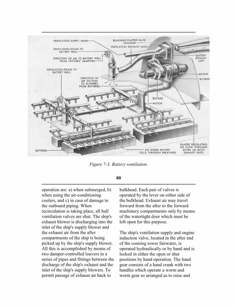
Figure 7-3. Battery ventilation.
80
operation are: a) when submerged, b)
when using the air-conditioning
coolers, and c) in case of damage to
the outboard piping. When
recirculation is taking place, all hull
ventilation valves are shut. The ship's
exhaust blower is discharging into the
inlet of the ship's supply blower and
the exhaust air from the after
compartments of the ship is being
picked up by the ship's supply blower.
All this is accomplished by means of
two damper-controlled louvers in a
series of pipes and fittings between the
discharge of the ship's exhaust and the
inlet of the ship's supply blowers. To
permit passage of exhaust air back to
bulkhead. Each pair of valves is
operated by the lever on either side of
the bulkhead. Exhaust air may travel
forward from the after to the forward
machinery compartments only by means
of the watertight door which must be
left open for this purpose.
The ship's ventilation supply and engine
induction valve, located in the after end
of the conning tower fairwater, is
operated hydraulically or by hand and is
locked in either the open or shut
positions by hand operation. The hand
gear consists of a hand crank with two
handles which operate a worm and
worm gear so arranged as to raise and

the forward machinery compartment,
all bulkheads between the forward end
of the after torpedo room and the
machinery compartments must be
open to the compartments surrounding
them by means of open exhaust
bulkhead valves or doors.
Two air-conditioning coolers for
cooling and drying the air are installed
in the supply lines; the larger forward
one is located in the after end of the
crew's quarters and the smaller after
one is located in the forward end of the
after machinery compartment. When
the humidity in the vessel becomes
excessive, the quantity of air passing
through the cooler should be reduced
in order that the temperature of the air
that passes through the cooler may be
lowered below the dewpoint and
thereby increase the quantity of water
extracted from the air. The coolers are
provided with drains to collecting
tanks or engine room bilges.
The supply and exhaust mains at the
watertight bulkheads are attached to
pressure-proof hoods surrounding
lever-operated bulkhead valves on
each side of the bulkhead. Each pair of
valves is operated by the lever on
either side of the bulkhead. No ship's
exhaust main exists aft of the ship's
exhaust blower, but provisions for
allowing exhaust air in the after end of
the ship to get back to the machinery
compartments have been made. Each
of the two watertight bulkheads at the
two ends of the maneuvering room has
a pair of light hoods surrounding
lever-operated bulkhead valves on
each side of the
lower the valve stem through the hull by
a bell crank and slotted lever
arrangement. A double-acting piston
type of hydraulic gear is in the power
position. The hand gear also moves the
hydraulic piston and can be used only
when the control lever for engine
induction on the flood control manifold
is in the neutral position.
External gagging on the engine
induction and ship's supply outboard
valve is accomplished by a wrench-
operated valve stem set flush with the
deck. The valve stem is supported by a
yoke superimposed on the valve body
and is protected by a cover projecting
slightly above the deck. Gagging of the
engine induction and ship's supply
outboard valve gags or position locks all
internal operating gear. The operating
gear for the engine induction and ship's
supply outboard valve is fitted with a
contact maker for the indicator lights in
the control room, thus indicating the
position (open or shut) of the valve.
There are four hull valves: one ship's
supply, two engine induction, and one
maneuvering room (auxiliary engine)
induction. All four valves are of the
flapper type and are gagged from the
inside of the ship. All hull valves seat
with pressure in the external piping
The operating gear for each of the
following hull valves, one ship's supply,
two engine induction, consists of an
operating lever and
81
a quick releasing gear located at a
suitable distance from the valve and
connected to it by means of
intermediate levers and connecting
rods. For opening each valve, the
operating lever must be used, and may
be used for closing to ease the valve to
its seat after tripping. However, the
valve can be shut in an emergency by
squeezing the handles, thus tripping
the quick-releasing mechanism which
permits the valve to seat by its own
weight.
The operating gear for each hull valve
is fitted with a contact maker for
indicator lights in the control room and
engine rooms to show open and shut
positions.
7A7. Hydrogen detecting systems. There are two types of hydrogen
detectors in service; one is
manufactured by the Cities Service
Company (type N.H.D.) And the other
by the Mine Safety Appliance
Company (type M.S.A.). The function
of the detectors is to take a sample of
exhaust air continuously from the
batteries and indicate the percentage of
hydrogen concentration in the battery
ventilation ducts.
The operation of both types of
detectors is based on the principle of a
balance Wheatstone bridge circuit.
The air sample is drawn, by means of
a motor-driven pump, across one leg
of the balanced circuit where it is
caused
to burn with an intensity dependent
upon the amount of hydrogen present.
The heat created heats the leg and
increases its resistance, thereby creating
an electrical unbalance in the entire
circuit. The meter connected across the
bridge circuit then shows a deflection on
a properly divided scale which is
directly proportional to the percentage
of hydrogen present in the air sample.
In addition to the meter indication, the
M.S.A. type has a white light connected
in the circuit, indicating normal
operation as long as the hydrogen
content is below 3 percent. When the
meter pointer indicates 3 percent on the
scale, the circuit to a red warning light is
closed. This red warning light will
remain ON despite a decrease in
hydrogen content until manually reset.
Both meter and light indications are
transmitted to repeater instruments in
the maneuvering room.
The type N.H.D. detector is supplied
with 115- to 120-volt alternating current
directly from the a.c. bus of the I.C.
switchboard. This system uses a rectifier
to convert the alternating current into
direct current for the bridge circuit.
The M.S.A. type detector is supplied
with 120-volt direct current from the
lighting feeder.
B. AIR PURIFICATION
7B1. General description. Air
purification is accomplished by the use
reaching 3 percent at the time of
surfacing.

of a CO2 absorbent as outlined in the
Bureau of Ships instructions. Thirty-
seven canisters, containing 15 pounds
each of CO2 absorbent, are carried in
stowages distributed in the several
living compartments.
The limiting percentage of CO2 is 3
percent. One percent or less is
harmless, and after air purification is
started, efforts should be made to keep
the percentage of carbon dioxide from
going above this amount. If, in any
case, it becomes necessary to conserve
the CO2 absorbent, the percentages of
carbon dioxide may be allowed to
increase during the last few hours of
submergence, barely
Two percent of carbon dioxide will
ordinarily not be noticed, but may show
some discomfort if work requiring
strenuous exertion is attempted.
Prolonged breathing of over 3 percent
CO2 causes discomfort in breathing
even at rest and becomes progressively
dangerous above 4 percent. The amount
of carbon dioxide should never be
allowed to exceed 3 percent. If, for any
reason, it does reach this concentration,
it should be reduced as rapidly as
possible. The limiting percent of oxygen
(O), on the other hand, should not fall
below 17 percent.
To maintain the air of a submarine
within these limits of purity, it is
necessary to
82
reduce the increasing CO2 by chemical
absorbents and to replenish the
decreasing supply of oxygen by
bleeding certain amounts of oxygen or
air into the submarine at regular
intervals.
After the original enclosed air in the
submarine has become so vitiated that
the limiting values of oxygen and
carbon dioxide have been reached, one
of the following procedures is
necessary to revitalize the atmosphere:
a) Bleed into the vessel 0.9 cubic foot
of oxygen at atmospheric pressure per
man per hour and at the same time use
the Navy standard carbon dioxide
absorbent.
b) In lieu of oxygen, bleed into the
vessel air from the compressed air
tanks at the rate of 31 cubic feet of air
c) Start the high-pressure air
compressors and pump a slight vacuum
in the submarine, charging this air into a
low air bank; then release air into the
submarine from a bank that was charged
on the surface.
Before submerging, whenever
circumstances permit, thoroughly
ventilate the vessel by closing the
hatches and ventilators in such a manner
that all the air for the engines is drawn
into the end compartments and through
the vessel. Under these conditions, run
the engines for 5 minutes.
Since the contained air in the vessel at
the outset of the dive is thus pure, it will
not reach the limiting values of 17
percent O and 3 percent CO2 until the
expiration of a period of hours (X),
calculated by the following formula:

at atmospheric pressure per man per
hour. The introduction of additional air
or oxygen is solely to replenish the
oxygen content in the compartment,
which, under normal submerged
operating conditions, should not be
allowed to fall below 17 percent.
Irrespective of whether compressed air
or compressed oxygen is used for this
purpose, the CO2 absorbent should
also be used, in view of the fact that
exhaustive tests have indicated that the
deleterious physiological effects of
high concentrations of CO2 are not
alleviated appreciably by the
introduction of additional oxygen or
air.
Figure 7-4. Carbon dioxide absorbent.
X = 0.04 C/N
where C = net air space of the
submarine in cubic feet, and N = the
number of men in the crew.
If submergence under ordinary
operation conditions is less than 17
hours, oxygen or compressed air
replenishment and CO2 purification
should not be necessary. However, if it
is predetermined that the time of
submergence will be greater in any case
than 17 hours, air purification with the
CO2 absorbent should be resorted to at
the end of the periods indicated for the
respective class of ship.
CO2 absorbent is considerably more
expensive than soda lime and great care
should be exercised in the handling and
stowage of the containers. Exposure of
them to external pressures, such as are
employed in testing compartments,
would probably rupture their seams and
destroy their airtightness, thus causing
eventual deterioration of the absorbent.
The containers should be removed
during air testing of compartments.
This chemical absorbs CO2, by contact.
The larger the area of the exposed
surface of the absorbent, the more
efficient will be the result. When the
length of submergence is such as to
necessitate CO2 elimination, the
following steps should be taken:
a. Remove the mattress covers from the
83
mattresses of four lower bunks in the
most convenient compartment
provided with outboard ventilation
when surfaced.
amount of heat evolved will be slight.
Consequently, when determining the
warmth of the chemical by touch, care
should be taken that the material is fully

b. Slit the mattress covers and spread
the covers, single thickness, as
smoothly and taut as possible over
bunk springs. Lash the edges to the
bunk spring, if necessary, to keep it
taut. Remove the cover from one of
the CO2 absorbent containers and pour
about one-fourth of the contents
(approximately 3 1/2 pounds) on the
cover. With a stick, spread the
chemical as evenly as possible over
the mattress covers. In pouring the
chemical from the container and in
spreading it on the mattress covers,
care should be taken not to agitate it
any more than necessary, as it is
caustic and the dust will cause throat
irritation. The irritation, however, is
only temporary and while in many
instances, coughing and sneezing may
be induced, the effects are not harmful.
After working with the chemical, do
not rub the eyes before the hands have
been thoroughly washed. If it should
get into the eyes, painful, but not
dangerous, irrigation will result.
It may be relieved by washing the eyes
with a solution of 1 part vinegar or
lemon juice and 6 parts of water, or by
careful washing with a quantity of
fresh water. Do not spread the
chemical with the hands. Use a stick or
other means. After spreading, stir it
gently once each hour.
Under normal submerged operation
conditions, the contents of one
container when spread on four
mattress covers, as outline above, will
absorb CO2 for 144 man hours, or will
absorb the CO2 produced by a crew of
33 men for approximately 4 1/2 hours;
a crew of 43 men for approximately 3
1/2 hours; a crew of 87 men
spent before renewing it. If there is any
doubt on this point, leave the material
spread on the mattress cover and spread
an additional charge on a split mattress
cover in an additional bunk.
Because of the desirability of keeping
the chemical from dusting as much as
possible, the refilling of the mattress
cover and the spreading of the chemical
should not be resorted to any oftener
than necessary. Accordingly, if
submergence of any particular vessel is
to exceed the time of CO2 protection
afforded by the chemical in the initial
container, the contents of the necessary
additional container or containers should
be spread out on additional mattress
covers in the amount necessary to
furnish the increased man hours of
protection required, in the same or other
convenient compartments, using
approximately 3 1/2 pounds of the
chemical on each additional cover. The
number of additional covers so used
should depend upon the total number of
men on board and the estimated total
time for which protection from CO2
must be afforded.
Higgins and Marriott carbon dioxide
testing outfits are supplied for
determining the percentage of carbon
dioxide in the air on submarines, and
one of the outfits should be carried on
each submarine. The test with this
apparatus is extremely simple and
sufficiently accurate for all practical
purposes.
7B2. Oxygen system. Eleven oxygen
standard containers are distributed
throughout the compartments of the
vessel, the total capacity being sufficient
to supply 37 cubic feet per man of
oxygen at normal temperature and
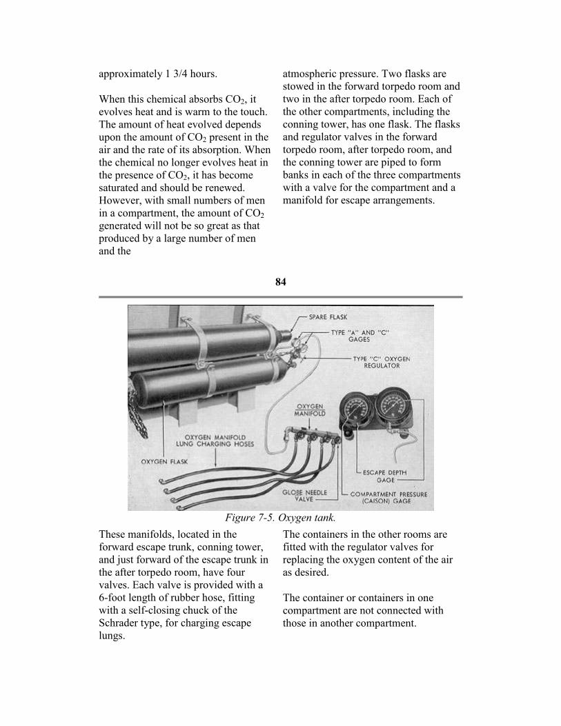
approximately 1 3/4 hours.
When this chemical absorbs CO2, it
evolves heat and is warm to the touch.
The amount of heat evolved depends
upon the amount of CO2 present in the
air and the rate of its absorption. When
the chemical no longer evolves heat in
the presence of CO2, it has become
saturated and should be renewed.
However, with small numbers of men
in a compartment, the amount of CO2
generated will not be so great as that
produced by a large number of men
and the
atmospheric pressure. Two flasks are
stowed in the forward torpedo room and
two in the after torpedo room. Each of
the other compartments, including the
conning tower, has one flask. The flasks
and regulator valves in the forward
torpedo room, after torpedo room, and
the conning tower are piped to form
banks in each of the three compartments
with a valve for the compartment and a
manifold for escape arrangements.
84
Figure 7-5. Oxygen tank.
These manifolds, located in the
forward escape trunk, conning tower,
and just forward of the escape trunk in
the after torpedo room, have four
valves. Each valve is provided with a
6-foot length of rubber hose, fitting
with a self-closing chuck of the
Schrader type, for charging escape
lungs.
The containers in the other rooms are
fitted with the regulator valves for
replacing the oxygen content of the air
as desired.
The container or containers in one
compartment are not connected with
those in another compartment.

C. VALVES
7C1. Classifications. The ventilation
system is provided with valves
classified as follows:
1. Engine induction and ship's supply
outboard valve. (Superstructure abaft
conning tower.)
2. Engine induction hull valve.
(Forward engine room.)
3. Engine induction hull valve. (After
engine room.)
4. Maneuvering room induction hull
valve. (Maneuvering room.)
5. Ship's supply hull valve. (Forward
engine room.)
6. Bulkhead flapper valves, supply and
exhaust.
All of these valves are described
separately in the following sections.
7C2. Engine induction and ship's
supply outboard valve. The engine
induction and ship's supply outboard
valve is a 36-inch disc type valve
(Figure 7-1), located in the air induction
standpipe in the superstructure abaft the
conning tower. (See FigureA-10.)
When open, this valve permits air to
enter the engine air induction and the
hull ventilation supply lines; when shut,
it
85

Figure 7-6 Engine induction hull valve.
86
prevents the entrance of air or water to
all three lines. It is operated
hydraulically from the control room
and is open only when the vessel is on
the surface. It can be operated
manually from the crew's mess.
7C3. Engine induction hull valve. There are two main engine induction
hull valves located beneath the
superstructure at those points where:
a. The port engine air induction line
goes through the pressure hull into the
forward engine room.
b. The starboard engine air induction
line goes through the pressure hull into
valve obtains its supply of air from a
damper fitting in the starboard engine
induction line located in the
superstructure. The maneuvering room
induction hull valve receives bypassed
air to cool the operating control stand in
the maneuvering rooms. The amount of
air that is bypassed is controlled from
the after engine room by a lever-
operated damper in the damper fitting.
7C5. Ship's supply hull valve. The
ship's supply hull valve obtains its
supply of air from the engine induction
and the ship's supply outboard valve.
The valve is similar in construction to
the engine induction hull valve shown in

the after engine room.
These valves are used to direct the
flow of air from the engine air
induction and ship's supply outboard
valve to the forward engine and after
engine rooms. Each is manually
operated from within the pressure hull.
Figure 7-6 shows the general
construction of a typical engine
induction hull valve.
Each valve is of the quick-closing
type, set into an angle housing. The
outboard, or inlet side of the housing
connects to the supply lines, bringing
air from the engine air induction and
ship's supply outboard valve in the
superstructure. The inboard, of
discharge side, leads into the pressure
hull.
The valve is operated by a linkage
extending to a hand lever. To open the
valve, the handle is moved downward
until the cam locking device is set.
This will hold the valve in the open
position. With the cam locking device
set, the valve handle is returned to its
former position. The valve, however,
is held open by a quick-releasing cam
locking device on an open hair trigger
for instant release and quick closing
when the locking handle is depressed.
This withdraws the locking device,
releases the cam, and allows the valve
to seat by its own weight. A link on
the moving arm actuates a switch
which, in turn, operates a signal light
in the control room, indicating the
position of the valve.
7C4. Maneuvering room induction
hull valve. The maneuvering room
induction valve is similar to but
Figure 7-6.
7C6. Bulkhead flapper valves. At each
point where the hull supply and hull
exhaust lines pass through a bulkhead,
two bulkhead flapper valves are
installed. There is no exhaust line aft of
the forward engine room and therefore
no exhaust flapper valve between the
forward engine room and the after
engine room bulkhead.
Figure 7-7 shows in schematic form the
general construction and arrangement of
a typical set of bulkhead flapper valves.
One valve is mounted on either side of
the bulkhead, with the pivot shaft
projecting downward and fitted with a
handle. The two pivot shafts are
interconnected by gears so that moving
one shaft and valve will operate the
other simultaneously. This arrangement
permits operating the valves from either
side of the bulkhead.
A locking device, extending through the
bulkhead, permits locking or unlocking
of the operating handles from either side
of the bulkhead.
When shut, the bulkhead flapper valve
stops all ventilating air flow to the
compartments forward or aft, as the case
may be, of the bulkhead on which the
shut valve is mounted.
Bulkhead flapper valves are also
provided on all bulkheads aft of the
forward engine room except the
bulkhead between the forward and after
engine room. These valves permit free
exhaust air to flow to the engine rooms.
All bulkhead flappers seat with
compartment pressure.

smaller than the engine induction hull
valve shown in Figure 7-6. This
87
Figure 7-7. Bulkhead flapper valves.
88

Figure 7-8. Ventilation operation condition No 1.
Figure 7-9. Ventilation operation condition No 2.
89

Figure 7-10. Ventilation operation condition No 3.
Figure 7-11. Ventilation operation condition No 4.
90

Figure 7-12. Ventilation operation condition No 5.
Figure 7-13. Ventilation operation condition No 7.
91

Figure 7-14. Schematic diagram of the ventilation system.
92
VENTILATION SYSTEM
TABLE OF OPERATING CONDITIONS
Number
of
Operation
AIR
CONDITION Position of valve and dampers
Condition of
vessel
Condition of
ventilation
A B C D F G
1. Figure
7-8 Stop Open Open Shut Shut F1 G1
On surface,
engines
STOPPED
Supply from
outboard.
Exhaust
outboard via
engine
rooms and
hatches.
2. Figure
7-9 Run Open Open Shut Shut F2 G1
On surface,
engines
STOPPED
Recirculating
and makeup
air is from
outboard.

3. Figure
7-10 Stop Open Open Shut Shut F2 G3
On surface,
engines
STOPPED
Supply from
inboard via
hatches and
engine
rooms.
Exhaust
outboard via
normal
supply pipe.
4. Figure
7-11 Stop Open Open Open Open F1 G1
On surface,
engines
RUNNING
Supply from
outboard.
Exhaust to
engine room.
5. Figure
7-12 Run Open Open Open Open F2 G1
On surface,
engines
RUNNING
Recirculating
and makeup
air is from
outboard.
6. Stop Shut Shut Shut Shut F2 G2 SUBMERGED
Recirculating
without air-
conditioning.
7. Figure
7-13 Run Shut Shut Shut Shut F2 G2 SUBMERGED
Recirculating
with air-
conditioning.
93
7C7. Chart of operating conditions. Valve and damper line-up for various
operating conditions is shown on the chart
on the
preceding page. In interpreting this chart it
is necessary to know the meaning of the
following symbols which are used
frequently:
KEY FOR TABLE OF OPERATING CONDITIONS
Symbol Meaning
A Engine induction and ship's supply outboard valve.
B Ship's supply hull valve.
D Forward and after engine room, engine induction hull valves.
E Maneuvering room induction hull valve.
F Exhaust blower discharge damper.
G Supply blower suction damper.
POSITION OF DAMPERS

F1 Exhaust blower to discharge into engine room and cross connection shut off.
F2 Exhaust blower to discharge into cross connection and engine room shut off.
G1 Supply blower suction on cross-connection and engine room shut off.
G2 Supply blower suction on cross connection and partial suction on engine room.
G3 Supply blower suction on engine room and cross connection shut off.
94
8
REFRIGERATING AND
AIR-CONDITIONING SYSTEMS
A. PRINCIPLES OF MECHANICAL REFRIGERATION
8A1. Brief statement of principles. The mechanical refrigeration method
used on board a submarine is the vapor
refrigerating process. In this process,
the refrigeration passes alternately
through its liquid and vapor states.
Such a refrigerant, therefore, must have
special qualities. It must boil at a very
low temperature and it must be able to
change its state from liquid to vapor
and vice versa readily. Above all it
must be a safe refrigerant. This is more
important in submarines than in other
types of vessels.
In the liquid state, the refrigerant picks
up heat from substances or the air in
spaces and in so doing, vaporizes. The
vapor, carrying the excess head, is then
moved away to another location where
it gives up or discharges that heat, and
is converted back to the liquid state.
The mechanical system in which the
refrigerant is contained is a single
airtight circuit of pipes and mechanisms
through which the refrigerant is
pumped continuously, so that a given
quantity is used over and over. This
requires an input of energy which is
from the point at which the heat to be
removed enters the refrigerating system.
This point is where the evaporator is
located. FigureA-11 shows a simplified
diagram of the main mechanical elements
in the cycle.
8A3. Through the evaporator. The
evaporator is simply a bank, or coil, of
copper tubing. It is filled with Freon 12
at low pressure and temperature. Heat
flowing from the air spaces or articles to
be cooled into the coil will cause the
liquid Freon to boil. Boiling can take
place only by the entrance into the liquid
of its latent heat of vaporization, and then
this latent heat can come only from the
surrounding substances. Hence, their
temperatures are lowered. The latter
portion of the evaporator coil is therefore
filled with Freon vapor at low pressure,
carrying with it the unwanted heat.
8A4. Through the compressor. This
vapor does not remain in the evaporator.
The compressor is operating and the
suction that it exerts (on the evaporator
side of its circuit) pulls the heat-laden
vapor out of the evaporator, through the
piping, and into the compressor. The

supplied by an electric motor. FigureA-
11 shows the cyclical arrangement of
the essential elements of the
refrigeration system; namely, the
evaporator, compressor, condenser,
receiver, and thermostatic expansion
valve. The liquid refrigerant picks up
heat and vaporizes in the evaporator.
The vapor then goes to the compressor
where it is compressed to a pressure at
which its temperature is above that of
the water flowing through the
condenser. The compressed vapor then
passes to the condenser where
sufficient heat is transferred to the
water to cause the refrigerant vapor to
condense. The condensed refrigerant,
now a liquid, flows next to the receiver,
and then through the thermostatic
expansion valve to the evaporator.
8A2. The Freon 12 cycle. Let us
follow through the cycle of operations,
starting
compressor, therefore, is the mechanism
that keeps the Freon in circulation
through the system. In the compressor
cylinders, the Freon is compressed from
a low-pressure vapor to a high-pressure
vapor and its temperature therefore rises.
8A5. Through the condenser. The
Freon vapor, now at high pressure, passes
next into the condenser, where the vapor
passes around the tubes through which
sea water is continuously pumped. Here
the excess heat flows by conduction
through the walls of the tubing from the
higher-temperature vapor to the relatively
lower-temperature sea water, and here,
therefore, the unwanted heat leaves the
primary refrigerating system and is
finally carried away. This excess heat
thus
95
flowing out of the vapor is latent heat
of vaporization and therefore, the vapor
condenses back to the liquid state. The
liquid Freon is now at high pressure
and high temperature.
8A6. Through the receiver. The liquid
Freon passes next into the receiver, or
tank. The liquid in this receiver acts as
a seal between the vapor in the
condenser and the liquid as it flows into
the next element, the expansion valve,
in order that the liquid Freon in the
expansion valve may be free of vapor.
The whole system is a single circuit in
which the fluid is circulated.
8A7. Through the expansion valve. The liquid Freon enters the expansion
and low temperature, and is reentering
the evaporator, its cycle completed, and
ready to be repeated. Every part of the
cycle is, of course, taking place
simultaneously throughout the circuit,
and continuously as long as the
refrigeration is wanted. The entire
operation is automatic.
8A8, The low-pressure side. That
portion of the cycle from the orifice of
the expansion valve around through the
evaporator to and including the intake
side of the compressor cylinders is called
the low-pressure side. The dividing line
between the low-pressure and the high-
pressure sides is the discharge valve of
the compressor.
valve at high pressure and high
temperature. This valve regulates the
flow of the refrigerant into the
evaporator. The liquid outlet from the
expansion valve is a small opening, or
orifice. In passing through the orifice,
the liquid is subjected to a throttling
action, and is dispersed into a finely
divided form. The Freon now is again a
vapor at low pressure
8A9. The high-pressure side. The
remainder of the cycle, that section from
the discharge valve of the compressor
around through the condenser, receiver,
and expansion valve to its orifice is
called the high-pressure side. The
dividing line between the high-pressure
and low-pressure sides is the thermostatic
expansion valve.
B. MECHANICAL DETAILS OF AIR-CONDITIONING SYSTEM
8B1. The air-conditioning cycle. The
air-conditioning cycle in the air-
conditioning system is the same as in
the refrigeration system. In general, the
mechanical circuit of equipment is also
similar, the main difference being that
the air is brought by forced ventilation
through ducts to the evaporators and
returned through ducts to the rooms.
8B2. The air-conditioning plant.The
air-conditioning plant consists of the
following main elements:
a. Two compressors, York-Navy Freon
12, enclosed single-acting vertical, two
cylinders, 4-inch bore x 4-inch stroke,
rated at 4 refrigeration tons each.
b. Two condensers, York-Navy Freon
12, horizontal shell-and-tube 4-pass
type.
c. Two receivers, York-Navy Freon 12
type.
d. Four evaporators, with finned
cooling coils in two casings.
e. Two conning tower evaporators, in
one casing.
8B3. Double system arrangement.
elements listed in Section 8B2 are
connected as two separate systems, each
containing all necessary valves, gages,
and controls for automatic operation. The
cooling coils of these two systems,
however, are placed side by side in an
evaporator casing, and though appearing
to be a single unit of coils, are,
nevertheless, entirely separate. Thus,
either of the two systems may be
operated alone, with its cooling action
taking place in the evaporating casing.
8B4. Interconnection of double system. The double systems, while ordinarily set
to operate individually, are
interconnected. On the 200 class
submarines, the interconnecting pipes run
between a) the discharge lines of the
condensers, b) the outlet lines of the
condensers, and c) the inlet or suction
lines to the compressors. Shutoff valves
in these interconnecting pipes permit any
of the main elements to be cut out of one
system and put into the other, in case of
necessity. There would be no flow in the
interconnecting pipes unless their shutoff
valves were opened; normally they are
closed. On the 300 class

The main
96
submarines, the interconnecting pipes
run between a) the discharge lines of
the compressors and b) the outlet lines
of the condensers. There is no
interconnection between the suction
lines of the compressors.
8B5. Capacity of the air-conditioning
system. The capacity of the air-
conditioning system is 8.0 tons of
refrigeration with the two compressors
operating at 330 rpm.
8B6. Necessity for compressors of
different capacities. The air
conditioning system and the
refrigeration system aboard a
submarine are designed as two separate
and distinct systems. Each is capable of
performing its task independently of the
other. However, in practice it is
desirable that these two systems be
interconnected so that the air-
conditioning compressor can serve as a
standby for the refrigeration system.
This will insure continuous operation of
the refrigerating system in the event of
a prolonged repair job on the
refrigerating compressor, which
otherwise would result in the spoilage
of the food stored in the refrigerating
rooms.
In earlier references and explanations
within this text, the rated capacity of
the refrigeration system compressor has
been given as 1/2 refrigeration ton,
while the rated capacity of each of the
air-conditioning system compressors is
given as 4 refrigeration tons. This
difference in rated capacity of the two
units is due to the fact that the air-
These requirements determine the work
load of each system, and this work load,
expressed in refrigeration tons,
determines in turn the capacity of the
compressor needed for each system.
8B7. Relation of capacities. The
capacity of the compressor is the amount
of work, expressed in refrigeration tons,
that a compressor is capable of
performing under a single set of
operating conditions. A change in the
operating conditions will cause a
corresponding change in the rated
capacity of the compressor. Therefore,
the relation between the capacity of a
compressor on a refrigeration system and
one on an air-conditioning system is a
comparison of the operating conditions
of evaporator temperature, speed of the
compressor, and temperature of the
cooling medium for each system, and not
a comparison of the compressor or its
maximum work load under optimum
conditions.
The misunderstanding of this relationship
has often given rise to a question as to
whether or not there is difference
between a ton of air-conditioning and a
ton of refrigeration. The cause of this
question is the apparent increase in the
capacity in refrigeration tons developed
by a compressor on an air-conditioning
unit over the capacity developed by the
same compressor when operating on a
refrigerating unit. Although it may
appear that there is a difference between
a refrigeration ton and an air-
conditioning ton, actually there is none
and the term air-conditioning ton is not

conditioning system performs a greater
amount of work than does the
refrigeration system. The refrigeration
system has to perform only sufficient
work to remove heat from the
comparatively small space of the cool
and refrigerating rooms, with the minor
addition of the ice cuber. Since these
two rooms are thoroughly insulated,
little or no heat enters them from the
outside. The only source of heat,
therefore, inside the rooms is from the
stowed foodstuffs and from persons
entering for supplies. The air-
conditioning system, on the other hand,
has to remove heat generated
throughout the ship. This is heat which
passes into the air of the ship from the
engines, crew, cooking, batteries,
electric light bulbs, equipment, and at
times from the surrounding water
outside the hull.
in acceptable usage.
The basic rating of refrigeration ton or
heat-removing capacity of a machine is
exactly the same whether the machine is
used for removing heat from an icebox or
lowering the humidity and/or temperature
of the air in a submarine. However, a
compressor that is rated at 2.95
refrigeration tons when operating at a -5
degree Fahrenheit evaporator
temperature, running at 600 rpm with the
same temperature of cooling water in the
condenser in both cases will have a rating
of 8,348 refrigeration tons if it is
operated at a 35 degree Fahrenheit
evaporator temperature. Thus, the rating
of a compressor may vary, depending
upon the evaporator temperature; also,
the rating of a compressor may vary,
depending upon
97
the speed of the compressor and the
temperature of the cooling water
flowing through the condenser. The
operating temperature of the evaporator
(suction pressure) will have the greatest
effect on the number of refrigeration
tons that the compressor will develop.
The higher the suction (and pressure),
the smaller the pressure differential
between the suction and discharge;
hence the compressor will handle more
Freon with less work. In other words,
the compressor will handle
approximately twice the gas at 40
degrees that it will at 0 degrees
Fahrenheit. Therefore, more
refrigeration tons are developed at the
higher evaporation temperatures
(suction pressure).
8B8. Cross connection of air-
pressure will be maintained in the air-
conditioning evaporator while the
compressor is operating on the lower
suction pressure necessary on the
refrigerating system. The operation of the
two systems in this manner is desirable
because the capacity of the air-
conditioning compressor is much greater
than is needed to maintain the
refrigerating rooms at their desired
temperatures.
The current supplied to the thermostatic
control on the refrigeration system is
another point that must be checked,
otherwise the solenoid valves will remain
closed and no refrigerant will flow
through the system. On some ships, the
thermostat circuits are energized from
110 volt d.c. so that in this case the main
thermostatic control circuit will still be

conditioning and refrigeration
system. In an emergency it is possible
to cross connect at least one of the air-
conditioning compressors, condenser,
and receiver, to the refrigerating system
evaporator and maintain the desired
temperatures in the refrigeration rooms.
On some classes of submarine, either of
the air-conditioning compressors may
be cross connected to the refrigeration
system; on other classes only the No. 1
air-conditioning compressor can be
used. As the arrangement and location
of valves and lines vary on each
installation, no detailed description can
be given here. It is never necessary nor
desirable to cross-connect the
refrigerating compressor to the air-
conditioning evaporators.
When cross-connecting the air-
conditioning compressor to the
refrigerating evaporator, there are
several major adjustments that must be
made on all installations. The low-
pressure cutout on the air-conditioning
compressor must be reset so that it will
not stop the compressor until the
suction pressure drops down to 2 psi.
Normally this cutout is set to stop the
compressor when the suction pressure
on the air-conditioning evaporator
reaches 32 psi. If the compressor is to
operate both the air-conditioning
system and the refrigerating system, the
bypass around the suction pressure
regulating valve should be closed, the
stops opened, and the valve cut into the
system. With the suction regulating
valve in operation, a 32-pound suction
energized. On some 300 class
submarines, the thermostat circuits are
energized through the refrigerating
control panel and when the main switch
is pulled on the refrigerating compressor,
it interrupts the supply to the thermostatic
control circuits. In this case, the
following procedure should be followed:
Leave in the main switch supplying
current to the refrigerating compressor;
with some insulated material, lift the
overload relay cutout located on the
bottom left side of the half-ton
compressor control panel, to the OFF
position, making sure that the overload
relay cutout stays up. Then turn the
selector switch on the half-ton system to
either MANUAL or AUTOMATIC. This
will insure a supply of current to the
thermostatic controls.
8B9. Cross connection of air-
conditioning systems. On some classes
of submarines, it is possible to operate
the No. 1 compressor and condenser on
the No. 2 evaporator and vice versa. The
air-conditioning systems on the 300 class
submarines are cross-connected only by
the compressor discharge lines and the
high-pressure liquid lines. There is no
cross connection between the suction
lines. Because of this arrangement in the
air-conditioning system, the No. 1
compressor can be connected to the No. 2
condenser, and the No. 2 compressor can
be connected to the No. 1 condenser. The
No. 1 compressor cannot be connected to
the No. 2 evaporator, nor the No. 2
compressor to the No. 1 evaporator.
98
9

WATER SYSTEM
A. INTRODUCTION
9A1. General. Although the,
submarine operates in large bodies of
sea water, the use of salt water aboard
the submarine is limited. Water, free of
salt and other impurities, is used for
cooling the diesel engines and in the
crew's cooking, drinking, and bathing
facilities. The torpedoes and the
torpedo firing mechanisms, as well as
the vacuum pump
tank, use distilled water. Distilled water
is also needed for the battery cells.
The water for all these operations is
either carried by the vessel or is distilled
on board. The purpose of the water
system is to store, distill, and distribute
water to the equipment requiring it. (See
Figure A-8.)
B. FRESH WATER SYSTEM
9B1. General description. Two of the
four main tanks of the fresh water
system are located in the forward end
of the forward battery compartment,
and two in the after end of the control
room below the platform deck. Fresh
water tank No. 1 is located between
frames 35 and 36 on the starboard side,
tank No. 2 between frames 35 and 36
on the port side, tank No. 3 between
frames 57 and 58 starboard, and tank
No. 4 between frames 57 and 58 port.
The fresh water tanks are connected by
means of the fresh water filling and
transfer lines. Supply branches connect
to the three emergency tanks,
lavatories, sinks, showers, scuttlebutts,
galley equipment, distilling
plant, and the diesel engines. A cross
connection is provided between the
filling and transfer lines of the fresh
water system and the filling and transfer
line of the battery system.
Two 60-gallon emergency fresh water
tanks are located on the port side in the
forward torpedo room. One 130-gallon
emergency fresh water tank is located on
the port side in the after torpedo room.
These tanks are connected to the fresh
water system, while the 18-gallon
emergency fresh water tank in the control
room, and the 8-gallon emergency fresh
water tank in the maneuvering room have
no connections to the fresh water
systems.
The fresh water filling valve and hose
connection (Figure 9-1), located in the
gun access hatch, connects with the fresh
water filling and transfer lines extending
to the forward and after ends of the
vessel. In the forward torpedo room, the
fresh water main has connections to the
No. 1 and No. 2 fresh water tanks. It also
has connections to the two 60-gallon
emergency fresh water tanks, the crew's

Figure 9-1. Ship's fresh water filling
valve.
lavatory, and the torpedo filling
connections. The 60-gallon emergency
fresh water tanks are equipped with their
own torpedo filling connections. The
quantity of water in the No. 1 and No. 2
fresh water tanks is measured by try
cocks located on the after bulkhead of the
forward torpedo room. (See Figure 9-2.)
In the officers' quarters, the fresh water
main supplies fresh water to the officers'
pantry, the shower, the lavatories, and the
hot water heater.
99
Figure 9-2. Try cocks.
In the control room, the fresh water
connections are to the fresh water tanks
No. 3 and No. 4 below decks, and the
fresh water transfer cutout valve from
No. 3 and No. 4 fresh water tanks. The
cross-connection valve between the
fresh water system and the battery fresh
water system is also in the control room
overhead.
In the crew's quarters, the fresh water
to the after engine cooling system and
purifiers.
There are no fresh water connections in
the maneuvering room. The fresh water
main aft terminates in the after torpedo
room where it supplies water to the
emergency fresh water tank, the after
torpedo filling connection, and crew's
lavatory. The emergency fresh water tank
is equipped with its own after torpedo

supply connections are to the galley
equipment, scuttlebutt, scullery sink,
and coffee urn. In the after end of the
crew's quarters, the fresh water main
supplies water to the two lavatories,
showers, and the hot water heater.
The water main in the forward engine
room is equipped with valves and
connections to the distilling plants, and
to the forward engine cooling system
and purifiers.
In the after engine room the fresh water
main is equipped with valves and
connections
filling connection.
9B2. Hot water system. Water for
washing and cooking is heated by electric
heaters. There are three electric hot water
heaters. One heater with a 20-gallon tank
is located in the starboard after corner of
the control room; two heaters each with
25-gallon tanks are located one in the
starboard forward corner of the forward
battery compartment, and the other in the
port after corner of the after battery
compartment. Each heating unit is
supplied with cold water from the fresh
water mains.
100
C. BATTERY WATER SYSTEM
9C1. Purpose. The cells of the forward
and after storage batteries must be
filled periodically to maintain a safe
level of liquid. The time between
fillings is dependent upon battery use
and operating conditions. The water
used in the battery cells must be free of
minerals and impurities which, while
harmless to human beings, may react
with the battery acid and plates to cause
corrosion and breakdown of the battery
cells. Therefore, only the purest
distilled water may be used for refilling
the batteries.
The purpose of the battery water
system is to store and supply distilled
water to the forward and after batteries.
9C2. Description and operation. The
battery water system consists
essentially of two groups of four tanks
each, filling and transfer lines, and
valves and branch piping with hose
forward battery water tanks with No. 5
and No. 7 battery water tanks located on
the starboard side, and No. 6 and No. 8
tanks on the port side. The battery water
filling valve and hose connection are
located in the gun access trunk. A cross
connection in the control room enables
the battery water system to be supplied
from the fresh water system. The battery
water filling line divides into the forward
and after supply lines, supplying water
directly to their respective tanks. The
supply line to the after battery water
tanks is connected to the distilling plant,
providing an additional supply of
distilled water for the batteries when the
distilled water in the battery water tank is
consumed.
The battery cells are filled by means of a
hose which is attached to the battery
filling connection, located on the battery
filling line connecting the port and
starboard tanks. The tanks are so

connections for filling the individual
battery cells. The four forward battery
water tanks, Nos. 1, 2, 3, and 4, are
located below deck in the forward
battery compartment and are arranged
in tandem, two on the port side and two
on the starboard. The after battery
water tanks are arranged similarly to
the
interconnected that any one of the tanks
can be used to supply the cells in either
of the two battery compartments. Each of
the two pairs of starboard and two pairs
of port tanks is equipped with capacity
gages accessible from the battery spaces.
D. GALLEY EQUIPMENT
9D1. Galley and scullery sinks. The
officers' pantry, the galley, and the
crew's mess room are provided with
sinks. Each is supplied with hot and
cold water. The sink drains are
connected to the sanitary drainage
system.
9D2. Coffee urn. The crew's mess
room is provided with a 5-gallon
electrically heated coffee urn with a tap
for drawing coffee in the mess room. A
cold water line supplies the urn with
water.
9D3. Scuttlebutt. The main drinking
water dispensing equipment aboard the
submarine is the scuttlebutt, or the
drinking fountain. One scuttlebutt is
located in the officers' pantry, and one
in the crew's mess room. Each
scuttlebutt is provided with a cold
water supply line and drain to the
sanitary tank drainage system. Before
the water enters the scuttlebutt in the
mess room, it is passed
through a cooling coil located in the cool
room. The water for the scuttlebutt in the
officers' pantry is cooled by the small
refrigerator in the pantry.
9D4. Lavatories and showers. Each
lavatory is provided with one cold water
line, a hot water line, and a drain to the
sanitary tank. There is one lavatory in the
forward torpedo room, two in the
officers' quarters, one in the commanding
officer's stateroom, one in the chief petty
officers' quarters, two in the crew's
quarters, and one in the after torpedo
room.
The showers are provided with hot and
cold water. The deck drain for each
shower is connected with the sanitary
tank drainage system. There is one
shower in the starboard forward corner of
the officers' quarters and two showers in
the after end of the crew's quarters.
101
E. PLUMBING
9E1. Sanitary drainage. All lavatories,
sinks, showers, scuttlebutts, and heads torpedo room lavatory, the refrigerator,
and the pantry sink.

drain into No. 1 and No. 2 sanitary
tanks through the sanitary drainage
system consisting of the sanitary
drainage piping and valves. The No. 1
sanitary tank, located inside the MBT
No. 1 has two sanitary drainage mains
connecting to it, one on the starboard
and one on the port side. The starboard
main to No. 1 sanitary tank receives the
drainage from the commanding
officer's lavatory, wardroom, stateroom
No. 1 lavatories, and the officers'
shower. The port drain receives
discharge from the chief petty officers'
lavatory, wardroom, stateroom No. 2
lavatory, the forward
The No. 2 sanitary tank, located in the
after starboard end in the after battery
compartment, receives the drainage from
the sanitary drain which collects the
discharge from the following: the galley
sink, the scullery sink, the scuttlebutt, the
crew's lavatories, the shower, and the
washroom decks. The officers' head in
the forward torpedo room empties
directly into the No. 1 sanitary tank; the
after head in the crew's quarters empties
into the No. 2 sanitary tank. The forward
head in the crew's quarters and the head
in the maneuvering room discharge
directly to the sea.
F. HEADS
9F1. Expulsion type head. There are
two air expulsion type water closets
(heads), each
Figure 9-3. Expulsion type head.
fitted with an auxiliary hand pump, one
in the crew's quarters, and one in the after
end of the maneuvering room. (See
Figure 9-3.)
The water closet installation consists of a
toilet bowl over an expulsion chamber
with a lever and pedal controlled flapper
valve between, which is weighted to hold
water in the toilet bowl and seats with
pressure of the expulsion chamber.
Each installation operates as a separate
unit with its own flood, blow, and
discharge lines. The toilet bowl is
provided with a sea flood with stop and
sea valves. The expulsion chamber has a
discharge line with swing check, gate,
and plug cock valves. The blow line to
the expulsion chamber receives air
through a special rocker valve which,
when rocked in one direction, admits air
from the low-pressure air service line
into a small volume tank until a pressure
of approximately 10 pounds above sea
pressure is reached. When rocked in the
opposite direction, the rocker valve

directs the volume of air into the
expulsion chamber. A sea pressure gage,
a volume tank pressure gage, and an
instruction plate are conveniently
located.
Before using a water closet, first inspect
the installation. All valves should have
been left shut. Operate the bowl flapper
valve to ascertain that the expulsion
chamber is empty.
102
Shut the bowl flapper valve, flood the
bowl with sea water through the sea
and stop valves, and then shut both
valves. After using the toilet, operate
the flapper valve to empty the contents
of the bowl into the expulsion chamber,
then shut the flapper valve. Charge the
volume tank until the pressure is 10
pounds higher than the sea pressure.
Open the gate and plug valves on the
discharge line and operate the rocker
valve to discharge the contents of the
expulsion chamber overboard.
Figure 9-4. Gravity flush type head.
Shut the discharge line valves and leave
the bowl flapper valve seated. For pump
expulsion, proceed as previously stated
except that the contents of the waste
receiver are to be pumped out after the
gate and plug valves on the discharge
line have been opened.
If, upon first inspection, the expulsion
chamber is found flooded, discharge the
contents overboard before using the
toilet. Improper operation of toilet valves
should be corrected and leaky valves
overhauled at the first opportunity.
9F2. Gravity flush type head. There are
two gravity flush type water closets
(heads), one in the forward torpedo room
for the officers, and one in the after end
of the crew's quarters. (See Figure 9-4.)
The water closet installation consists of a
toilet bowl over a waste receiver with a
lever and pedal-controlled flapper valve
between, which is weighted to hold water
in the toilet bowl and seats with the
pressure in the tank.
Each toilet bowl is provided with a flood
line with stop and sea valves. The water
closets are located over the sanitary tanks
and discharge directly into them.

Before using a water closet, first inspect
the installation. All valves should have
been left shut. Operate the bowl flapper
valve to ascertain that the waste receiver
is empty. Shut the bowl flapper valve,
flood the bowl with sea water through the
sea and stop valves, and then shut both
valves. After using the toilet, operate the
flapper valve to empty the contents of the
bowl into the waste receiver and sanitary
tank.
G. DISTILLATION
9G1. Submarine distilling equipment. The distillers in use on modern
submarines are either the Kleinschmidt
Model S, or the Badger Model X-1.
Two stills are installed on all later class
submarines. The Kleinschmidt model is
discussed and illustrated in this text.
(See Figure 9-5.)
9G2. Consumption of fresh water. A
modern submarine during a war patrol
will consume on the average
approximately 500 gallons of fresh water
per day for cooking, drinking, washing,
and engine make-up water. In addition to
this consumption, the main storage
batteries require about 500 gallons
103
of battery water per week; giving a total
requirement of at least 4000 gallons per
week. This minimum requirement will
allow each man in the crew to have a
bath at least twice a week.
9G3. Fresh water stowage capacity. The normal fresh water stowage
capacity is about 5400 gallons; 1200
gallons of this is battery water and is
stored in the battery water tanks. This
water will last only about 10 days and it
is good practice not to allow the fresh
water on hand to drop below one-half
the normal capacity. The area of
operations is usually the determining
factor as to when the distillers can be
used.
9G4. Principles of distilling action. The knowledge of distilling liquids
The distiller can be supplied with feed
water from the main engine salt water
circulating pump sea suction, from the
main motor circulating water system, and
from the ship's fresh water system. The
latter feed is used when redistilling ship's
fresh water for battery use.
Part of the sea water flows out of the still
as distilled water, and collects in the
distillate tank. It can be transferred by
blowing to the fresh water system or to
the battery water system for stowage.

comes from ancient days. Distillation is
simply the boiling of a liquid and the
condensing of its vapor to the liquid
state again. In the boiling, much or all
of any impurities or undesired contents
are left behind, so that the condensed
liquid is free of them. If a teaspoon is
held in a cloud of steam arising from a
teakettle, the vapor will condense on
the spoon and the resulting liquid is
distilled water.
9G5. The purifying action in
distilling sea water. In sea water, salt
and other substances are dissolved or
held in solution. Sea water does not
boil at the same temperature, 212
degrees F, as does fresh water, but at a
temperature a few degrees higher.
When the sea water boils, it is only the
water (H2O) that is vaporizing at this
temperature, and if that pure vapor is
led to another clean container where it
may condense, the result: is pure
distilled water. The salt (sodium
chloride) and other solid ingredients of
the sea do not vaporize and hence do
not come over into the distilled water.
9G6. Brief explanation. A brief
explanation is given of the actions that
take place in the Kleinschmidt still,
without mentioning mechanical details,
in order that these actions may be easily
understood.
The distilling process in the
Kleinschmidt still is continuous, with
sea water being supplied at the rate of
about a gallon per minute.
Figure 9.5. Kleinschmidt distillers.
The desuperheating tank, the purpose of
which is to supply the cooling water to
the still and to lubricate the lobes of the
compressor at the top of the still, can be
replenished from the distillate tank. The
remaining sea water is concentrated brine
and flows out separately.
Inside a cone-like casing, a long length of
tubing is coiled. This casing is set with
104
the small end down. Actually there are
ten such cones, nested together. Cold
sea water enters at the bottom between
temperature lower than its new
condensation point, and so is able to
condense. This type of apparatus is

the cones; that is, it flows around the
outside of the tubing. Here, on its way
up, it is heated, so that it is boiling
when it emerges from between the
cones at the upper end. The vapor is led
through a vapor separator into a
compressor, where it is compressed,
and is then discharged down into the
inside of the tubing. On the way down
through the tubing, this vapor is
gradually cooled by contact with the
colder tubing walls, finally condensing
therein and flowing out as pure distilled
water to a storage tank. The nested
cones of tubing, therefore, act as a heat
exchanger. The distilled water is
technically known as distillate or
condensate.
9G7. Necessity of compressing the
vapor. A question may arise as to why
the vapor is compressed in the still. The
explanation involves several
considerations:
The conical crest of tubes serves three
purposes: 1) vaporization of the feed
water, 2) condensation of the vapor,
and 3) cooling of the hot condensed
liquid to a lower temperature. In the
lower part of the nest, the feed water is
at the temperature of sea water; the
temperature increases during the
upward flow, so that the feed water
leaves the nest boiling. The feed water
in the upper part of the nest is therefore
very hot. On the downward flow, the
vapor is condensed in the upper part of
the nest, and in the lower part of the
nest, the hot condensed liquid is cooled.
Sea water does not boil at the same
temperature, for a given pressure, as
does fresh water, but at several degrees
higher. The feed water in the upper part
of the nest is, therefore, actually above
accordingly called a vapor compression
still.
9G8. Heat input of still. Compression of
the vapor serves another purpose also.
On starting operation of the still, the feed
water is brought up to boiling
temperature by the electric heaters. After
the still is in normal operation, there will
be a steady heat loss of definite amount
through the insulation and in the
outgoing condensate and brine overflow.
This heat loss is balanced by an input of
energy from the electric motor, which is
transformed to heat by the compression
of the vapor. Theoretically, this input of
heat by the compressor maintains the
heat balance at a constant level, and it is
possible to operate the still with all
electric heaters turned off. In actual
practice, however, most of the heaters are
usually left on after the still is in normal
operation.
9G9. Vent to atmosphere. Since the
boiling of the sea water takes place inside
the shell of the still, it is necessary to
prevent any increase of pressure on the
boiling water, for increased pressure here
would raise the boiling point and put the
whole system out of balance and
probably out of operation. The situation
is different in the compressor; when the
vapor goes into the compressor, it is
sealed off from the boiling liquid and
may then be compressed without
affecting the boiling point. Therefore, in
order that the boiling may always take
place at atmospheric pressure as found
within the submarine, a pipe called the
vent leads from the vapor separator and
out through the bottom of the still. This
vent, being open to the atmosphere at its
end, insures that the pressure in the vapor
separator is always at the pressure of the
surrounding atmosphere. A distant

212 degrees F. But the vapor from the
boiling water is no longer sea water; it
is fresh water vapor, and fresh water
vapor at atmospheric pressure can
condense only at 212 degrees F. When
a vapor is compressed, its boiling point,
or its condensation point, rises. By
compressing the vapors in the still, its
condensation point is raised above the
temperature of the hot feed water in the
upper part of the nest. Therefore, when
the compressed vapor enters the nest, it
finds a
reading dial thermometer is connected by
a flexible tubing to the vent to give the
temperature in the vent pipe.
Although this open vent pipe leads
downward out of the still, the steam
when in normal amount inside will not
flow out, because of the pressure of the
outer atmosphere
105
through the vent. Actually, the interior
and exterior pressures are so
maintained that there is a very small
excess of pressure inside the still. This
causes a slight feather of steam to
appear at the vent, which is an
indication that the still is operating
satisfactorily. Any excess steam that
the compressor cannot handle,
however, will be able to pass out
through the vent, which thus acts as a
safety device.
The vent pipe also serves to permit
drainage to the bilge of any slight
amount of liquid carried into the vapor
by the violent boiling action, and
prevents it from gathering on the floor
of the vapor separator. A small drain
tube leading down from the compressor
to just above the vent pipe in the vapor
separator also permits water and oil to
drain from the compressor seal out
through the vent.
9G10. Portion of sea water not
distilled. All of the incoming sea water
cannot be distilled, for some must
remain undistilled to carry away the
concentrated salt content left from the
height as to insure that the interior
overflow heat exchanger is always full of
liquid, and therefore always exerts its full
heating effect on the sea water inside.
9G12. Time required to start sea water
boiling in still. When starting the still,
from 60 to 90 minutes are required to
bring the temperature up to the boiling
point.
9G13. Heat balance in the still. It may
be interesting to indicate the heat flow
through

distilled portion. This undistilled
portion, which is concentrated brine, is
maintained at a level just above the top
coil of the heat exchanger by overflow
pipes. It flows down through these
overflow pipes into a separate conical
passage, called the overflow heat
exchanger, located around the nest of
tubes, where it gives up some of its heat
by conduction through the metal walls,
thus helping to heat the incoming feed
water.
9G11. Overflow weir cup. The
overflow pipe, after leading out of the
overflow heat exchanger at the bottom
of the still casing, rises again a short
distance. At the top of the upright
overflow pipe, the brine flows out
through an opening called the weir,
which meters or measures the quantity
of brine overflow in gallons per hour.
The overflow brine passing out of the
weir falls into an open cup and then
drains down to a storage tank called the
brine receiver, from which it is
discharged to the sea.
Since water in any U-shaped container
must always be at the same level in
both arms of the U, the open weir is
located at such a
Figure 9-6. Distiller controls.
the various parts of the still in actual
quantities. The following is an example:
Heat input: 10,185 Btu per hour come in
through the compressor; 5,940 Btu per
hour come in through the electric heaters.
This is after the still is fully operating.
The total input of heat is 16,125 Btu per
hour.
106
Heat loss: This total quantity of heat
flows out through four separate paths,
as follows:
1,825 Btu per hour in condensate,
11,600 Btu per hour in overflow, 400
Btu per hour from vent, 2,300 Btu per
hour by radiation from hot metal parts,
or a total heat loss of 16,125 Btu per
hour. The heat balance is not always at
this exact number of Btu per hour, for
separate stills (Figure 9-6) each with its
necessary control devices.
Two stills are necessary, not only as a
safety factor, but also to provide
sufficient distilled water. These stills may
normally be run 300 to 350 operating
hours without cleaning. Each gives 40
gallons per hour. This means a total of
24,000 to 28,000 gallons of distilled
water. The consumption of distilled water

various momentary changes or rate of
feed and temperature of sea water,
voltage fluctuations in motor, or other
operating conditions, will naturally
cause it to vary around any average
number. This heat balance of the still is
very sensitive and all changes that may
be necessary in the operation conditions
should be made slowly.
9G14. Purity of the distilled water. If
no leaks are present, the distilled water
will contain only about one part of salt
to a million parts of water. The distiller
cannot, of course, remove any volatile
liquids; that is, liquids that boil at or
below the boiling temperature of water.
For example, in badly polluted harbors
or streams, a trace of ammonia may be
present in the distilled water; and in
improperly chlorinated waters, a trace
of chlorine may likewise come over in
the distilled water.
9G15. Two-still system. In the
complete submarine distilling system,
there are two
is about 600 gallons per day for all
purposes. On a war patrol lasting 60
days, the total consumption will be about
36,000 gallons, and may run higher in the
tropics.
9G16. Water for the storage batteries. Distilled sea water is fit for human
consumption and for the storage
batteries. It may happen that fresh water
is taken on board from some shore
source. Such fresh water is not suitable
for storage battery use until it has been
distilled. Fresh water taken aboard in any
foreign port should always be boiled or
distilled before use. Only fresh water
definitely known to be pure may be used
without distilling or boiling for drinking,
cooking, or personal use. In distilling
fresh water that is taken aboard, the
operation of the still is practically the
same as when distilling sea water, the
difference being that the overflow is
returned to the ship's fresh water tanks
from the brine tank instead of being
discharged overboard.
107
10
TRIM AND DRAIN SYSTEMS
A. TRIM SYSTEM
10A1. General description. As
explained in Chapter 5, the balance and
stability of the submarine can be upset
by an unequal distribution of weights in
the ship. The trim system is employed
chiefly to correct this condition by
regulating the quantity of water in the
variable tanks.
FigureA-12 illustrates the general
lines; all of these tanks make up the
variable ballast tanks group. The
remaining flood and suction lines are
connected to the negative and the safety
tanks, called the special ballast tanks.
Cross connection of the trim pump and
the drain pump is made by two flanged
connections on the after end of the
longitudinal axis of the manifold. One

arrangement of the trim system in the
submarine. It shows the trim pump
manifold, the main flood and suction
lines, the valves, and the connections to
the various trim system tanks.
The trim manifold, located on the port
side aft in the control room, is the
center of control for the entire system
in that it directs the flow of water to the
various tanks. It is a casting divided
into two longitudinal compartments
known as the suction and discharge
sides. The discharge side of the
manifold contains eight discharge
control valves. One of these valves is
the trim pump discharge valve and
connects the discharge side of the
manifold with the discharge side of the
trim pump. The suction side of the
manifold contains eight suction control
valves, and is connected to the suction
side of the pump through the trim pump
suction valve.
The remaining seven discharge and
seven suction valves control the flood
and suction from the following lines:
1. Trim pump suction and
overboard discharge line.
2. Trim line forward flood and
suction.
3. Trim line aft flood and suction.
4. Auxiliary ballast tank No. 1
flood and suction.
5. Auxiliary ballast tank No. 2
flood and suction.
6. Negative tank flood and suction.
7. Safety tank flood and suction.
The trim lines forward and aft serve the
two trim tanks and the two WRT tanks,
while auxiliary ballast tanks No. 1 and
No. 2 are served by their own flood and
connection is on the discharge side, the
other on the suction side.
The trim pump, located in the after end
of the pump room, provides pumping
power for the system. It draws water into
its suction side, through the suction side
of the manifold, from the tank being
pumped, and discharges it through its
discharge side into the discharge side of
the manifold, which directs the water to
the tank being filled. When it is desired
to pump to one of these tanks by means
of the trim pump, the discharge valve on
the trim pump manifold controlling this
particular tank is opened. When water is
to be removed from a tank by means of
the trim pump, its valve on the suction
side of the manifold is opened. Thus, the
trim manifold control valves serve to put
any part of the trim system on suction or
discharge. For example, in pumping from
forward trim tank to after trim tank, the
water is drawn through lines from the
forward trim tank through the suction
side of the manifold and into the suction
side of the trim pump, and forced by
pump action through the discharge side
of the trim pump, through the discharge
side of the trim manifold, and then
through lines into the after trim tank. The
trim line forward is a 3-inch line
extending from the trim manifold in the
forward torpedo room. The forward trim
manifold controls the flooding and
pumping of the forward trim tank and the
forward WRT tank.
The trim line aft is also a 3-inch line,
terminating in the after torpedo room at
the after trim manifold, which controls
the flooding

suction
108
and pumping of the after trim tank and
the after WRT tank.
The Nos. 1 and 2 auxiliary ballast tanks
are piped directly to their suction and
discharge valves on the trim pump
manifold. The flooding or pumping of
these tanks can be accomplished only
through the trim manifold. On the other
hand, the flooding and draining of the
safety and the negative tanks can be
accomplished in two ways: either by
the use of their suction and discharge
valves on the trim manifold, or directly
from sea by use of their flood valves. In
the latter case, the blowing is
accomplished by opening the flood
valves and admitting compressed air
into the tanks, thus forcing the water
out; while the tanks are flooded by
opening both the flood and the vent
valves, allowing the sea to enter
directly into the tanks.
The trim pump suction and overboard
discharge line, connecting the trim
manifold with the sea, provides the trim
system with an overboard discharge to,
or direct flooding from, the sea. In
addition to the suction and discharge
valves on the trim manifold, this line
has also a sea stop valve and a
magazine flood valve. The sea stop
valve is used to shut off the sea from
the trim system and the magazine flood
valve. The magazine flood valve
guarantees, when the sea stop valve is
open, an immediate source of sea water
to the ammunition stowage and the
pyrotechnic locker.
As stated before, the main function of
water ballast from one variable tank to
another, adding water to the variable
tanks or discharging excess water from
the tanks overboard. Therefore, the water
handled by the trim system is measured
in pounds; and a gage, graduated in
pounds to show the amount of water
transferred by the trim pump, is located
above the trim manifold where the
operator can observe its reading.
Because the trim pump used on the latest
fleet type submarine is of the centrifugal
type, it must be primed before beginning
the operation. A priming pump is used
for this purpose. It primes the trim pump
by removing all air from the trim pump
casing, the trim manifold, and the lines
leading to it, thus allowing water to
replace the air in this equipment and fill
it completely. It should be noted that
some submarines are equipped with a
trim pump of the reciprocating or plunger
type, similar to the drain pump shown in
Figure 10-5.
The trim system can also be used to
supply or drain water from the torpedo
tubes. Water for flooding torpedo tubes is
normally taken from the WRT tanks
through tube flood and drain lines. These
lines are controlled by the torpedo tube
flood and drain valves.
The trim line forward and the trim line
aft are provided with hose connections,
one in each compartment of the
submarine. These connections can be
used for fire fighting, or for bilge
suctions in those compartments that do
not have bilge suction facilities. Of
course, if the connections are used for

the trim system is to shift and adjust the
distribution of weight throughout the
submarine. This is done by means of
transferring
bilge suction the trim line must be on
suction, and if for fire fighting, the line
must be on discharge.
B. TRIM PUMP
10B1. Source of power. The trim
pump, Figure 10-1, located on the port
side of the pump room just forward of
the after bulkhead, is driven by a 10/25
horsepower motor directly connected
by means of a flexible coupling to the
drive shaft of the trim pump.
The controller relay panel for the motor
is mounted on the after bulkhead of the
pump
room. However, the motor is started or
stopped by push button controls in the
control room. Once started by these
controls, the speed of the pump and,
thereby, the rate at which water is moved
in the system, is regulated by a rheostat
control, also located in the control room
just below the push button switch (Figure
10-2).
109

Figure 10-1. Trim pump.
110

Figure 10-2. Trim pump controls.
While the trim pump is driven by an
electrical motor, the starting of the
motor does not guarantee that the trim
pump will pump water, for the trim
pump, being of the centrifugal type,
cannot pump air. Therefore, it cannot
be operated until the system is free of
air.
10B2. Priming pump. Freeing the
system of air is the purpose of the
priming pump, located outboard of the
trim pump. Since any appreciable
amount of air entering the inlet side of
the trim pump will cause it to lose
suction and thereafter run without
pumping, it is necessary to know when
this critical condition has been reached.
To indicate the amount of air in the
trim system a vacuum gage is provided
which is mounted in the control room.
When the vacuum gage indicates less
than 21 inches of vacuum, the priming
pump must be operated before the trim
pump is started. The priming pump,
like the trim pump, is started by push
button controls located in the control
room. The
priming pump is a vacuum pump with a
float valve in the line, running from the
priming pump to the trim manifold and
the trim pump casing. The valve consists
of a float with a ball-ended stem. The
purpose of the float is to permit the
passage of air and to prevent the passage
of water into the priming pump. As the
water rises in the float valve, the upper
part of the ball-ended stem is
automatically forced against the valve
seat, thus preventing the sea water from
entering the priming pump.
The priming pump is a self-priming
centrifugal displacement pump consisting
of three major parts: rotor, lobe, and port
plate. The rotor is made up of a series of
curved plates projecting radially from the
hub. The lobe is elliptical in shape and
forms the outer casing for the rotor. The
port plate consists of two inlet and two
outlet ports corresponding to the inlet and
outlet ports on the rotor. The pump is
end-mounted on the direct driving
electric motor as shown in Figure 10-3.

111
Figure 10-3. Priming pump.
112
Before starting the priming pump, it is
necessary first to provide seal water to
it. This water is needed to fill the lobe
partly and provide a water seal. Water
obtained from the seal water tank
should be added until the seal water
The periphery of the impeller is open, as
shown in Figure 10-1.
In operation, water enters the eye of the
impeller, is picked up by the vanes and
accelerated to a high velocity by the

gage shows two-thirds full. (See Figure
10-3.) Serious damage may result if the
pump is allowed to run in a dry
condition. The motor is then started by
the push button control in the control
room.
In operation, the rotor revolves in the
lobe, which has been partially filled
with water, at a speed high enough to
throw the water out from the hub by
centrifugal force. This results in a solid
elliptical-shaped ring of water
revolving at the same speed as the
rotor. In Figure 10-3, showing rotor
operation, it may be seen that a ring of
water for a given rotor section, guided
by the lobe, will move in and out from
the hub, forming a liquid piston. As the
rotor passes the inlet port, the water
ring is farthest from the hub, and air is
permitted to enter. As the rotor
advances to discharge port, the air
space becomes less and air is forced out
the discharge port. This cycle is
repeated twice for each revolution of
the rotor. When the vacuum gage
registers 21 inches of vacuum in the
trim system, the priming pump can be
stopped and the trim pump started.
10B3. Operation of the trim pump. A
brief review of the general principles of
centrifugal pumps will be helpful in
understanding the operation of the trim
pump. As the name implies, this type of
pump employs centrifugal force to
move a liquid from a lower to a higher
level. In its simplest form, the
centrifugal pump consists of an
impeller rotating in a watertight casing
provided with inlet and outlet ports.
The impeller consists of two parallel
disks with curved vanes or bulkheads
radiating from the hubs and between
rotation of the impeller, and discharged
by centrifugal force into the casing and
out of the discharge port. When water is
forced away from the eye of the impeller,
a suction is created and more water flows
in. Consequently there is a constant flow
of water through the pump. An air bubble
in the inlet port of the pump will interrupt
the action of the pump since it will, upon
entering the impeller, break the suction at
the eye which is dependent on the
presence of water. For this reason, the
pump casing and the system served by
the pump must be solidly filled with
water before pumping is commenced.
This is the function of the priming pump.
The centrifugal pump described above
has only one impeller and is known as a
single-stage pump; a pump with four
impellers would be known as a four-stage
pump; with six impellers, a six-stage, and
so on. In practice however, any pump
with more than one stage is referred to as
a multi-stage pump.
The mechanical details of the trim pump
are shown in Figure 10-1. It will be seen
that it is a six-stage centrifugal pump.
The valve shown on the forward end
permits either parallel or series operation
and is manually operated. The schematic
diagram in the upper right corner of the
illustration shows the flow of the water
being pumped for both series and parallel
operation. With the manually operated
series-parallel valve in the SERIES
position, the incoming water enters the
first stage, proceeds through the second
and third stages, and then back through
the series-parallel valve to the fourth,
fifth, and sixth stages. With the series-
parallel valve in the parallel position, half
of the inlet water proceeds through the
first, second, and third stages, and is then
discharged through the series-parallel
valve. Simultaneously, the other half of

the disks. One of these two disks (upper
or lower, depending upon where the
water is brought in) has an inlet port or
circular opening called the eye,
concentric with the hub of the impeller.
Actually then, one disk holds the
impeller to the shaft while the other
admits the water.
the inlet water is directed by the series-
parallel valve to the fourth, fifth,
113
and sixth stages and is then discharged
directly. Series operation of the pump
produces twice the discharge pressure,
but only one half the volume produced
by parallel operation. The pump is
operated in series only when the
submarine is at depths of approximately
250 feet or more and discharging to the
sea, the higher pressure being necessary
to overcome the greater sea pressure
encountered at that depth.
not be started if this gage registers less
than 21 inches of vacuum. If the gage
shows less than 21 inches, the system
must be restored to the proper condition
by using the priming pump. When the
gage registers the required 21 inches, the
priming pump is stopped and the trim
pump started.
The trim pump should not be operated at
speeds greater than are necessary to
produce a rate of flow specified for a
given depth. The accompanying table
lists the valve
DEPTH PUMP OUTPUT VALVE POSITION
On surface 1,500-2,500 pounds per minute Parallel
0-200 ft. 1,500 pounds per minute Parallel
200-250 ft. 1,250 pounds per minute Parallel
400 ft. or deeper 1,000 pounds per minute Series
250-400 ft. 1,000 pounds per minute Series
To summarize, it must be remembered
that before starting the trim pump, it is
necessary to make certain that the trim
system lines and the pump casing are
free of air, as explained earlier in this
section. A vacuum gage is provided to
indicate the condition existing in the
system. The trim pump must
position and pump output in pounds of
water per minute, recommended at
different depth levels.
The pump should not be operated at a
motor speed greater than 2,400 rpm.
Excess speeds place an overload on the
bearing and mechanical parts of the
pump and may cause a breakdown.
C. MANIFOLDS
10C1. Trim manifold. In section A of board mounted directly above it.

this chapter, the trim manifold is
referred to as the center of distribution
for the trim system. It acts as a
switchboard between the trim pump
and the lines of the system, providing a
centralized station to direct the flow of
water to and from the variable tanks.
Used in connection with the trim
manifold, but connected to each
variable tank, is a measuring gage, or
liquidometer. These gages record the
amount of water in each tank, and
provide the diving officer with an
indication of the amount of water
ballast being redistributed by the trim
manifold through the trim system. The
trim manifold is mounted hip-high of
the port side of the control room just
forward of the after bulkhead, with the
gage
Figure 10-4 shows the mechanical
construction of the trim manifold, and
also the proper nomenclature of its
details.
It will be seen that the manifold is a box-
like, two-piece casting divided internally
into two longitudinal compartments,
known respectively as the suction and
discharge sides. The suction side contains
eight suction control valves, while the
discharge side has eight discharge (or
flood) control valves. Each of these 16
valves is of the dish and seat type, with
rising stems and individual bolted-on
bonnets. Name plates attached to each
bonnet indicate the function of that
particular valve.
114

Figure 10-4. Trim manifold.
Starting from the after end outboard of
the trim manifold, the valves in the
suction
and discharge sides control the
following components:
OUTBOARD (Suction) INBOARD (Discharge)
1. Trim pump suction 9. Trim pump discharge
2. Auxiliary ballast tank No. 2 suction 10. Auxiliary ballast tank No. 2 discharge
3. Auxiliary ballast tank No. 1 suction 11. Auxiliary ballast tank No. 1 discharge
4. Safety tank suction 12. Safety tank discharge
5. Negative tank suction 13. Negative tank discharge
6. After trim line suction 14. After trim line discharge
7. Forward trim line suction 15. Forward trim line discharge
8. Sea suction 16. Discharge to sea
The discharge valves are all on the
starboard side of the manifold with the
corresponding suction valves opposite
them on the port side. A special
forward of the torpedo tubes. (See
Figure A-12.)
The forward and the after WRT and trim

wrench is provided for operating the
valves.
Flanged outlets are cast integral with
the manifold to connect with the lines
of the system. Two outlets on the after
end lead to the drain line cross
connection and to the drain pump
discharge to permit emergency use of
the drain pump to actuate the trim
system.
In all pumping operations, the trim
pump suction and the trim pump
discharge valves on the manifold must
be opened to permit flow within the
system. To flood a tank, the discharge
valve for that tank must be opened at
the trim manifold; to pump a tank, its
suction valve must be opened. This
should be done before the trim pump
is started. All valves on the manifold
should be shut immediately after the
pumping operation is complete. Figure
10-4 shows the direction of flow when
flooding or pumping auxiliary ballast
tank No. 2.
10C2. Forward and after WRT and
trim tank manifold. The WRT and
trim tank manifolds are used in
conjunction with the trim manifold to
control the flooding and pumping of
thre WRT tanks and the trim tanks,
both fore and aft.
The forward trim manifold is located
in the forward torpedo room, portside,
aft, of the torpedo tubes. The after trim
manifold is located in the after torpedo
room, portside,
tank manifolds are identical in operation
and construction, differing only in the
fact that they serve different tanks.
The body of each trim manifold is a two
chambered casting containing two
valves which control flood and suction
of the WRT tank and the trim tank
respectively. The after valve in the after
torpedo room and the forward valve in
the forward torpedo room control the
trim tanks. The valves are of the disk
and seat type with bolted bonnets. The
connecting passage between chambers
of the integrally cast valve casting
allows either valve to be operated
independently. The handwheels carry
name plates designating the uses of the
individual valves.
When open, the manifold valve marked
trim tank flood and suction permits the
flooding or pumping of the trim tank
from or into the trim system when the
trim line is on service.
The other valve, marked WRT tank
flood and suction, permits the flooding
or pumping of the WRT tank from or
into the trim system when the torpedo
tube drain stop valve to the WRT tank is
open.
10C3. Torpedo tube drain manifold. In Section A of this chapter, the
flooding and draining of the torpedo
tubes were mentioned as functions of
the trim system. These functions are
controlled by the torpedo tube drain
manifolds. Two of these manifolds are
located in
116
the forward torpedo room, each
servicing three torpedo tubes; and two
attached to the back of the casting.
Separate control levers and connections

in the after torpedo room, each
servicing two torpedo tubes.
The body of the torpedo tube drain
manifold is a three-chambered casting,
housing three cam-actuated plunger
type valves, and provided with flanged
outlets for connection to the trim
system and to the torpedo tube drains.
The cam mechanisms are
are provided for each of the valves.
Each, hand lever operates one cam
through the action of its connecting rod
and cam lever. In draining or flooding
the tubes, the manifold valves are used
in conjunction with the torpedo tube
drain stop valve to the WRT tank which
must be open when draining from the
tubes to the WRT tank.
D. VALVES
10D1. Trim pump sea stop valve. When it is desired to discharge water
ballast from any part of the trim
system to sea, the trim pump sea stop
valve must be opened, thus providing
a passage from the trim manifold
through the pressure and outer hulls to
the sea. The same line is used to
permit water to enter the system from
the sea when additional water ballast is
to be added. This valve is located on
the port side of the control room,
directly below the trim manifold. (See
FigureA-12.)
10D2. Torpedo tube drain stop valve
to the WRT tank. The torpedo tube
drain stop valve to the WRT tank
serves as a stop valve between the
WRT tank and the individual torpedo
tube drain valves.
There is a torpedo tube drain stop
valve
to the WRT tank in both the forward and
the after torpedo rooms. Both of these
valves are identical in function and
construction.
10D3. Magazine flood valve and
testing casting. The magazine flood
valve and testing casting provide an
emergency method of flooding the
magazine compartment.
The magazine flood valve is used to
control this emergency flooding system.
The testing casting is used to check the
magazine flood valve to make certain
that it is ready for immediate use. Both
the magazine flood valve and the testing
casting are located in the control room
on the magazine flood line of the trim
system. The accessory box, containing
the operating plug and wrench, is
mounted directly above the testing
casting.
E. DRAIN SYSTEM
10E1. Functions. In submarines, as in
all ships, a certain amount of water
accumulates inside the hull from
various sources. The most important of
with the operation of the submarine.
This water is pumped out by the drain
system which consists essentially of the
drain pump and the piping connecting

these sources are:
a. Leakage at glands around propeller
shafts, Pitometer log, sound gear,
periscopes, and similar equipment.
b. Draining of air flasks, manifold
drain pans, conning tower deck gun
access trunk, and escape trunk.
c. Condensation from air-conditioning
cooling coils.
This water drains off into the bilges
and wells where a number of bilge
sumps with strainers are provided,
from which the bilge water can be
pumped.
The bilge sumps and wells are pumped
periodically to prevent the excess free
water from overflowing the bilges and
interfering
the pump with the sumps and other
drainage points in the submarine. The
general arrangement shown in FigureA-
12 is used in the following functional
description:
The drain pump located in the pump
room provides the suction for the drain
system. The pump is started and stopped
by means of an electric push button
switch located nearby in the pump
room. The drain pump has a suction and
a discharge connection. A suction line
equipped with a strainer and a sight
glass connects the suction side of the
pump with the main forward and after
drain lines, called the drain line forward
and the drain line aft. The drain line
forward
117
and the drain line aft can be cut off by
shutting their respective stop valves
located in the pump room.
Proceeding forward from the pump
room, we note that the drain line
forward extends to the forward
torpedo room and provides pumping
connections for the two bilges and the
underwater log well in the after section
of the torpedo room. The drain line
terminates at the forward bilge
manifold with two valves controlling
the suction from the poppet valve
drain tank and the forward bilge.
The escape trunk drain opens into the
forward torpedo room; the water
drains directly onto the deck and
The drain water from the gun access
trunk, the cable trunk, the periscopes,
and the antenna wells empties into the
pump room bilge and collects in the
sumps from which it is pumped when
required.
The drain pump has three points to
which it may discharge: 1) overboard
discharge, 2) compensating water main,
3) trim system.
In addition, the drain pump is so cross
connected with the trim manifold that it
can discharge water into the trim system
instead of into its own piping. This cross
connection permits the use of either the
drain pump or the trim pump with either
the trim or the drain system, in the event

eventually empties into the bilges.
There are no drain line connections in
the forward battery compartment.
The drain line aft extends to the after
torpedo room and contains pumping
connections to the sumps in the
compartments in the after section of
the submarine. There are no drain line
connections in the after battery
compartment. The forward engine
room has two bilge sumps connecting
with the drain line aft through two
individual lines. The after engine room
also has two bilge sumps which
connect to the drain line by means of
two separate lines. In addition to the
bilge sump pumping connections, the
drain line aft also contains a suction
line to the collection tank, making it
possible for water from the collecting
tank to be pumped out through the
drain system.
There is one bilge sump in the motor
room.
The drain line aft terminates in the
after bilge manifold in the after
torpedo room. Here, too, the manifold
contains two valves, controlling
suction from the forward and after
bilge sumps.
Returning now to the pump room, the
drain pump suction line carries a
branch connection to the pump room
bilge manifold. This manifold contains
three valves controlling suction front
the three pump room bilge sumps.
that one of the two pumps is not in
operating condition.
Every branch suction line to the bilge
sumps has its own bilge stop valve.
When it is desired to pump out certain
bilge sumps or wells, the valves leading
from them to the drain line and the
pump are opened; then the required
discharge valves are opened to the
overboard discharge, the compensating
water main, or the trim system,
depending upon the conditions. The
drain pump is then started and the
pumping begins. After the pumping is
completed, the pump is stopped and the
valves to the various lines used in the
operation are shut.
The drain system can discharge the bilge
water directly overboard, into the
expansion tank through the
compensating water main, or into the
trim system through the trim manifold.
Normally, bilge water should not be
discharged directly overboard because
the oil in it will rise to the surface,
indicating the presence of the
submarine. Instead, the water should be
pumped into the expansion tank, where
the water separates from the oil before
being discharged overboard.
If the trim system is used to receive the
bilge drainage, it is possible to pump
this water into the variable ballast tanks.
This should not be done normally,
because discharging variable tanks to
sea during trimming operations will
allow bilge oil to rise to the surface,
leaving the telltale oil slick.
118

F. DRAIN PUMP
10F1. Source of power. An electric
motor, rated at 10 hp and 1,150 rpm, is
used to drive the drain pump through a
worm and worm gear assembly as
shown in Figure 10-5. There are two
types of pumps used: one with
vertically mounted motor as shown in
the large cutaway view of Figure 10-5,
and the other with the motor mounted
horizontally as shown in the small
illustration. The cutaway view shows
the mechanical construction of the
pump.
10F2. Description. The drain pump is
a single-acting duplex reciprocating
pump with the cylinders mounted
vertically. The two plungers are
connected to the crankshaft by
connecting rods, so that one plunger
completes its downward travel at the
moment the other plunger completes
its upward travel. As a plunger moves
upward in the cylinder, it creates a
vacuum (suction) which draws water
into the cylinder through the valves
from the inlet, or suction, port. When
the plunger reaches the top of its
stroke and starts its downward travel,
the water forces the suction valve
down, closing the inlet port, opening
the discharge valve, and allowing the
water to flow out of the discharge port.
At the same time, the second plunger
is performing the reverse operation,
taking a suction, while the first
plunger is discharging. This results in
a continuous flow of water through the
pump.
An air chamber is provided for each
cylinder to smooth out the flow and
quiet the pump operation by
cushioning the discharge.
Air in the chamber is compressed during
the discharge. When the plunger reaches
the end of its stroke, expansion of the air
tends to keep the water flowing until the
reverse stroke begins.
A connection is provided to the 225-
pound air system for recharging the
chambers. Indicator lights show when
the chambers need charging or venting.
10F3. Lubrication. Lubrication of the
main and the connecting rod bearings is
accomplished by the multiple oiler
mounted on the pump casing. Oil is led
to the bearings by holes drilled through
the crankshaft and connecting rods. The
worm gear drive runs in oil, which is
cooled by sea water circulating through
a coil installed in the worm drive
housing.
10F4. Relief valve. The relief valve, set
at 225 psi, is mounted on the pump body
and protects the pump from excessive
pressure in case a valve is shut on the
discharge line when the pump is
operating.
A drain cock is provided to allow the
draining of all water from the pump.
10F5. The drain pump controls. The
electrical controls for the drain pump
consist of the motor switch, the air
chamber pressure indicators, and control
panel. All of these are mounted on the
port side of the pump room.
The motor switch is equipped with a
push button for starting, a push button
for stopping, and a signal light that is on
when the motor is running. (See Figure
10-6.)

G. VALVES AND FITTINGS
10G1. Drain line stop values. The
drain system is provided with two
valves, known as the forward and the
after drain line stop valves
respectively. These valves will put
either drain line on service, depending
on which section of the boat is to be
serviced. The valves are located on the
port side of the pump room, forming
the connection between the line
leading to the suction side of the drain
pump and the forward and after drain
lines.
The forward drain line stop valve is an
angle valve of the disk and seat type
with a bolted bonnet, a rising stem, and
flanges for connection to the lines. The
after drain line stop valve is a globe
valve.
10G2. Drain pump overboard
discharge valve. When the water
collected from the bilges by the drain
system is to be discharged directly to the
sea, two valves must be opened to
provide passage for the drain water.
119

Figure 10-5. Drain pump.
120

Figure 10-6. Drain pump controls.
The inboard valve is a stop check
valve; the second valve is outboard of
the first and is known as the drain
pump overboard discharge valve. Both
are located on the port side forward in
the pump room, and are mounted in
tandem so that the stop check valve
acts as a sea stop for the discharge
valve.
10G3. Bilge strainer. Although the
purpose of the bilges is to collect
excess water, a miscellany of solid
material such as flakes of paint and
bits of metal inevitably finds its way
into the bilges. If this solid matter
were to enter the lines of the drain
system, it might clog or damage the
drain pump. To prevent this, each
bilge sump is equipped with a bilge
strainer which screens the bilge water
before it enters the drain system lines
and holds back any large particles.
10G4. Macomb strainer. Although
the bilge strainers discussed in Section
10-G3 will prevent pieces of solid
material larger than 1/2 inch from
might clog or damage the drain pump.
Such material is filtered out of the drain
system by the Macomb strainers.
10G5. Drain line sight glass. The drain
sight glass provides a means of visually
determining the amount of oil of solid
matter in the bilge water as it flows
through the lines of the drain system. It
consists of a cross-shaped casting, two
ends of which are flanged and connected
to the drain lines. The other arms are
fitted with glass plates forming a
window to allow inspection of the water
in the drain line.
10G6. Underwater log well suction
line and sump. The water that collects
in the underwater log well is pumped
out by the underwater log well suction
line. This line extends from the drain
line and runs athwartships along the
after bulkhead of the forward torpedo
room to the underwater log well.
It is equipped with a bilge strainer
which is fitted into the well. A stop
check valve is mounted in the line

entering the drain system, it is
necessary to screen the water again to
remove any smaller particles of debris
that
between the well and the forward drain
line which is opened to pump the
underwater log well.
121
11
AIR SYSTEMS
A. GENERAL DATA
11A1. Importance of the air systems
to submarines. The importance of the
air systems to a submarine cannot be
overemphasized, for virtually every
function in the diving and surfacing
procedure stems initially from air
provided by one or more of the air
system; to cite a few:
a. The main hydraulic system operates
because of the air pressure maintained
in the air-accumulator flask.
b. Torpedoes are discharged from the
submarine by air.
c. Tanks are blown by air.
d. The main propulsion engines are
started by air.
Air, or more specifically, compressed
air, is necessary to surface, submerge,
attack, and cruise. In addition,
compressed air together with oxygen is
used to revitalize the air in the ship
after long periods of submergence.
Pressure in the boat, a test for
tightness, utilizes air.
The air systems represent, therefore, the
most versatile of all systems aboard a
more operations than any other single
system.
11A2. Basic principles of compressed
air. The actuating force of the air
systems is compressed air, which, as the
name implies, is air under pressure
confined within the limits of a container.
The force required for compression of the
air is provided by the high-pressure air
compressors, a simple machine that
compresses air by means of a series of
pistons designed so that one or more
pistons discharges air into another for
further compression and finally through
lines to banks for storage. Air can be
compressed easily aboard a submarine, as
it requires a relatively small plant and
comparatively simple equipment. It can
be stored at any convenient place and is
always ready for use. Its action can be
regulated to produce a low or high-
pressure, and yet it has enough elasticity
or compressibility to cushion its impact
against the equipment it operates. It
consumes no valuable materials and can
be supplied to any part of the submarine
simply by extending a line from the air
supply. Air, once stored, requires no
further expenditure of energy for
operation, but rather is a source of power
to other equipment.

submarine, in that they are capable of
performing, either as primary or
secondary functions,
B. TYPES AND RELATIONSHIPS OF AIR SYSTEMS
11B1. General information. There are
five air systems on the submarine: the
3,000 pound high-pressure and torpedo
impulse system; the 600-pound main
ballast tank (MBT) blowing system; the
225-pound service air system (ship's
service air); the 10-pound main ballast
tank (MBT) blowing system; and
finally, the salvage air system. (See
FigureA-13.)
The 600-pound MBT blowing system
and the 225-pound service air system
receive their supply of air from the
3,000-pound air system. The 10-pound
MBT blowing system is an independent
system with its own low-pressure
blower. The internal compartment
salvage air system is dependent upon the
225-pound service air system, while the
external compartment salvage air system
is entirely dependent upon an outside
source for its supply of air.
11B2. The 3,000-pound and torpedo
tube impulse air system. This system
consists of the 3,000-pound high-
pressure compressors, the high-pressure
manifold, the interconnecting piping,
valves, and compressed air banks. The
main function of the 3,000-pound air
system is to compress, store and supply
air at the maximum pressure of 3,000
pounds per square inch for use within the
3,000-pound, the 600-pound, and the
225-pound systems.
122
The 3,000-pound air system also
supplies air to the hydraulic
accumulator air loading manifold and
to the forward and after 600 pound
Grove reducing valves which supply
the forward and after torpedo tube
impulse charging manifolds.
The 3,000-pound air system is
equipped with air external charging
connection so that the system may be
supplied with air from an outside
source.
11B3. The 600-pound MBT blowing
system. The only function of the 600-
pound MBT blowing manifold and
system is to remove water ballast front
the main ballast tanks or the fuel ballast
aboard the submarine. The 225-pound
system consists of the 225-pound service
air manifold, interconnecting piping, and
various valves.
11B5. The 10-pound MBT blowing
system. When the submarine has
surfaced, the 10-pound main ballast tank
blowing system is used to conserve the
compressed air stored in the ship's air
banks. The system consists of its own
low-pressure blower, control manifold,
and piping to the various main ballast
tanks. The 10-pound system is operated
only after the submarine has, surfaced
sufficiently to permit the opening of
induction valves and hatches.
11B6. The salvage air system. This

tanks when used as main ballast tanks.
It receives its supply of compressed air
from the high-pressure system through
the distributing manifold.
11B4. The 225-pound service air
system. The 225-pound service air
system or, as it is sometimes called,
ship's service air, is so called because,
in addition to blowing the variable
group of tanks, it provides the
compressed air for all the
miscellaneous services
system is actually three separate systems:
the MBT external salvage, the
compartment external salvage, and
compartment internal salvage. The
external salvage connections permit
compressed air from an outside source to
be supplied to the tanks and/or
compartments, while the internal salvage
system utilizes the ship's air for,
compartment salvage only.
C. HIGH-PRESSURE AIR AND TORPEDO IMPULSE AIR SYSTEMS
11C1. General description. FigureA-
14 shows the location and relationship
of the individual units that comprise the
high-pressure 3,000-pound air system.
It should be noted that 3,000 pounds is
the maximum working pressure of the
system end not a constant pressure.
Actually, the pressure may vary
between 1,500 and 3,000 psi. The
system is hydrostatically tested to 4,500
psi or 150 percent of the working
pressure. The system extends from the
high-pressure air compressors in the
pump room to the receiving and
distributing manifolds in the control
room, and from there forward to the
torpedo impulse air system in the
forward torpedo room, athwartship to
the air banks, and aft to the after
torpedo room.
In Sections 11C1 through 11C4, a more
detailed description is given of the
general layout of the high-pressure air
system. The control room, the air
banks, and the torpedo impulse air
system fore and aft of the control room
are discussed.
11C2. Manifolds and lines. The high-
pressure manifold, made up of a
receiving manifold and two distributing
manifolds, is mounted on the starboard
side of the control room. The receiving
manifold receives air up to 3,000 psi
from two high-pressure air compressors,
and directs it to the air banks where it is
stored. The capacity of each compressor
is 20 cubic feet per hour at 3,000 psi. As
the air is needed, it flows back through
the same piping to the receiving manifold
where it is directed to the distributing
manifold. This operation is controlled by
the valves on the manifold.
The 3,000-pound service air lines supply
air at a pressure up to 3,000 psi to the
forward and after torpedo rooms, to the
engine starting flasks, and to the reducing
valves in each engine room which furnish
500-pound air used in starting the diesel
engines.
The distributing manifolds distribute air
to the safety and negative tank blow
lines, the main ballast tanks blow
manifold, the
123

Figure 11-1. Compressed air systems.
124
hydraulic accumulator air flask, the
high-pressure air bleeder, the bow
buoyancy tank blow line, the 225-
pound service air system, and the
forward and after 3,000-pound service
air lines.
11C3. Air banks. Each of the five air
banks consists of seven flasks, with
the exception of the No. 1 air bank
which has eight. Each flask is
provided with a drain valve. The total
capacity of the air banks is 560 cubic
feet.
The No. 1 air bank is located inside
charging manifolds and six impulse
flasks connected by lines to the
manifolds. The impulse flasks are
mounted above the pressure hull in the
superstructure forward. One impulse
flask charging manifold is located on the
port side of the torpedo room and the
other on the starboard side. Each
manifold is used to charge three flasks
with 600-pound air.
The 3,000-pound air service line aft,
extending from the distributing
manifold, ends with a 3,000-pound to
600-pound reducing valve, through
which air is furnished to the after

the pressure hull, with four flasks in
each battery, compartment. The other
four air banks are located in the main
ballast tanks. (See FigureA-14.)
11C4. Torpedo impulse air system. The torpedo impulse air system stores
and controls the air used to discharge
the torpedoes from the tubes.
The 3,000-pound air service line
forward, extending from the
distributing manifold, ends with a
3,000-pound to 600-pound reducing
valve, from which a line leads to the
forward torpedo impulse air system.
This system is composed of two
impulse flask
torpedo impulse air system. This system
consists of one impulse flask charging
manifold with lines leading to the four
impulse flasks provided for the four
after torpedo tubes. The impulse flasks
are mounted below the after torpedo
room deck; the manifold is located on
the starboard side.
In both the forward and the after
sections of the torpedo impulse system,
a bypass valve and line are provided,
leading from the 3,000-pound air service
line to the charging manifold. The
bypass valve and line allow the charging
of the impulse flasks in the event of
failure of the reducing valves.
D. THE 600-POUND MAIN BALLAST TANK BLOWING SYSTEM
11D1. General description. The main
ballast tanks are filled with sea water
when the submarine is submerged.
These tanks cannot be pumped.
Therefore, when the submarine is
surfacing, compressed air must be
used to blow the water out through the
flood ports to the sea.
Two separate systems are provided to
blow the main ballast tanks. This
section describes the first of these, the
600-pound MBT (main ballast tank)
blowing system. The second system,
the 10-pound MBT blowing system, is
used only when the ship is surfaced.
FigureA-15 shows the location of the
lines and component parts of the 600-
pound MBT blowing system. The
system is inside the pressure hull and
extends from the MBT blowing
manifold in the control room fore and
aft along the starboard side to the main
distribution control unit of the system. It
is located on the starboard side of the
control room with its pressure gage next
to it. The piping mounted directly above
the manifold connects the MBT blowing
manifold with the high-pressure air
manifold through two hammer valves.
The maximum working pressure of the
600-pound main ballast tank blowing
system is 600 psi. It is tested
hydrostatically to a pressure of 1,000
psi, or 166 percent of the maximum
working pressure.
Air at bank pressure (1,500 to 3,000 psi)
passed through two manually operated
hammer valves and two group stop
check valves to the 600-pound MBT
blowing manifold. The flow of the air is
regulated by the hammer valves so that
it is delivered at the required pressure.
Normally, only one hammer valve is
used for blowing; in case one does not

ballast tanks and fuel ballast tanks.
The MBT blowing manifold is the
supply enough air or in case of failure,
the other hammer valve can be used.
The
125
group stop check valves permit the
blowing of tanks by groups. The
manifold is protected by a sentinel
valve and two relief valves set to blow
when the pressure in the 600-pound
system reaches 750 psi. A sentinel
valve is set to blow at a pressure of
610 psi. When the sentinel valve
opens, it acts as a relief valve for
comparatively small rises in pressure
and gives notice of excessive pressure
in the system.
To supply air to the 600-pound MBT
blowing system, one of the hammer
valves is opened. The valve permits air
from the 3,000 pound manifold to
enter the MBT blow manifold at a
reduced pressure. The pressure gage of
the MBT blow manifold is closely
watched to guard against the pressure
exceeding 600 pounds.
The depth at which the submarine is
operating will have a direct effect on
the resistance offered to the air in
blowing the main ballast tanks and,
therefore, the pressure will be built up
within the system more rapidly at
greater depths than it will on the,
surface. Since the hammer valve
regulates the volume of the air
entering the 600-pound MBT blowing
system, while the resistance offered to
this air varies with submerged depth, it
follows that, when submerged at great
depths, the hammer valve must be
opened cautiously, otherwise the
pressure within the system will build
up rapidly and exceed the safe
maintain the required pressure. When
blowing is finished, the hammer valve is
shut.
Blow lines extend from the forward
section of the 600-pound MBT blow
manifold to tanks No. 1 MBT, Nos. 2B
and 2D MBT. Nos. 2A and 2C MBT,
and Nos. 3A and 3B FBT. From the
after section of the manifold, blow lines
extend to tanks Nos. 4A and 4B FBT,
Nos. 5A and 5B FBT, Nos. 6B and 6D
MBT, Nos. 6A and 6C MBT, and No. 7
MBT. Any tank or any combination of
tanks can be blown by opening the
required individual tank valve, or
valves, the group valves, and finally the
hammer valves.
When the submarine is rigged for
diving, all the blow valves on the
manifold, except the fuel ballast tanks
valves, are open, as are the two group
stop check valves. The individual
regulator valves at the main ballast tanks
are open, while the MBT blow hammer
valves on the 600-pound manifold are
shut. The two supply valves to the 600-
pound MBT blow manifold on the
distributing manifold are open.
To operate the 600-pound MBT blow
system, the hammer valve is opened and
air is admitted to the blow manifold,
from which it is directed to the main
ballast tanks by the lines of the system.
Each blow line is provided with a
regulator valve at the point where it
enters the tank. The regulator valve acts

working pressure. When the gage
indicates that the pressure is dropping,
the hammer valve is opened wider to
as a combination stop and check valve
and is equipped for securing the stop in
any position required to equalize the
flow of air into the tanks.
E. THE 225-POUND AIR SYSTEM (SHIP'S SERVICE AIR)
11E1. General description. The 225-
pound service air system, known as
the ship's service air system, performs
or controls many operations other than
those discussed in the sections dealing
with the 3,000-pound, the torpedo
impulse, and the 600-pound air
systems. The 225-pound air system
provides the air for approximately 100
operations. The system extends from
the forward torpedo room to the after
torpedo room, with service
connections in every compartment of
the vessel, and supplies air at pressure
ranging. from 225 psi to 8 psi. The
center of direction
of the system, the 225-pound service air
manifold, is located in the control room.
The 225-pound system is hydrostatically
tested to 350 psi, or 155 percent of its
maximum working pressure of 225 psi.
FigureA-16 shows the, location and
relationship of the parts of the system,
as well as their nomenclature.
The discussion of the ship's service air
system starts with the control room,
describing each component part of the
system located there, and explaining its
function in the operation of the
submarine. A similar
126
procedure is followed for each of the
compartments of the vessel,
proceeding first forward and then aft
of the control room.
11E2. Control room. The 225-pound
service air manifold is located in the
control room on the starboard side aft
of the high-pressure manifold. This
manifold receives its supply of air
through two Grove pressure-reducing
valves which reduce the high-pressure
air from 3,000 psi to 225 psi. Stop
valves are provided on the low-
pressure side of the 225-pound Grove
reducers, cutting them off the 225-
pound system. This permits removal of
a Grove reducer without impairing the
operation of the 225-pound system.
supplies 225-psi and air to the hydraulic
oil supply volume tank, the signal
ejector, the drain pump air domes, the
negative tank blow valve, and the sea
pressure and depth gage blows.
The other branch of the line from the
Grove reducing valves supplies air to
the 225-pound service air manifold. This
air is directed by means of valves to the
forward and after service air mains, the
auxiliary tank blow and vent lines, and
the forward and after trim tank blow and
vent lines. A hose connection to the
manifold provides for air supply from
the shore or tender.
A reducing valve from the forward
service air main furnishes air at pressure

The 225-pound service air manifold
can also be supplied from the 225-
pound bypass which is controlled by a
manually operated 225-pound bypass
valve located at the high-pressure
distribution manifold. Where the 225-
pound bypass is used, the high-
pressure air bypasses the reducing
valves and is admitted directly into the
225-pound system. The bypass valve
is only partly opened so that the
pressure can be built up gradually. The
225-pound manifold pressure gage
must be constantly watched and the
pressure must never be allowed to go
beyond 225 psi.
The 225-pound service air system is
protected by one sentinel valve and
two relief valves located on the line
between the Grove reducers and the
225-pound manifold.
When the air within the 225-pound
system reaches a pressure of
approximately 250 psi, the sentinel
valve opens, allowing the excess air to
escape into the compartment. The
sentinel valve has a comparatively
small capacity and serves primarily to
warn that the normal working pressure
is exceeded. If the rise in pressure is
rapid and above the capacity of the
sentinel valve, the two relief valves,
set to operate at 275 psi, open and
allow the excess air to escape into the
compartment.
The relief valves and the sentinel valve
shut automatically when the normal
working pressure is restored.
The supply line from the Grove
reducing valves has two branches. One
branch
of 100 psi to a connection for pneumatic
tools. A bypass is provided for
emergency operations, with a relief
valve set to open at a pressure of 110 psi
as a protection against excessive
pressure. It also carries a connection
supplying air to the whistle and siren.
The after service main has branch
connections to the sea pressure gage and
to the compartment air salvage. It also
supplies air through a reducing valve at
a pressure of 12 psi to fresh water tanks
No. 3 and No. 4. A bypass is provided
for emergency operation, with a relief
valve set to open at a pressure of 15 psi.
11E3. Forward battery compartment. In the officers' quarters, the forward
service air main supplies the
compartment air salvage valve mounted
on the after bulkhead. This valve can be
operated from either side of the
bulkhead. A branch of the service line,
passing through an 8-pound reducing
valve, supplies air at a pressure of 8 psi
to the four battery water tanks Nos. 1, 2,
3, and 4 in the forward battery
compartment. A bypass line is provided
for emergency operation, with a relief
valve set to open at a pressure of 10 psi.
11E4. Forward torpedo room. In the
forward torpedo room, the forward
service air main extends to the torpedo
tube blow and vent manifold. The
service main is also provided with
branch lines to the torpedo stop
cylinders, the escape trunk blow, the
volume

127
tank, the sanitary tank, the QC and JK
sea chests, the underwater log, the
compartment air salvage valve, and the
fuel oil blow and vent manifold. Two
other branch lines, equipped with
reducing valves and bypass lines,
furnish air to the pneumatic tool
connection at 100 psi, and to the No. 1
and No. 2 fresh water tanks at 12 psi.
The line to the escape trunk supplies
air for the ship's diver's air,
connection, and a blow and vent line
for the escape chamber. The forward
trim tank blow and vent line from the
225-pound manifold in the control
room terminates at the forward trim
tank and connects with the forward
trim tank blow and vent line from the
forward torpedo tube blow and vent
manifold.
11E5. After battery compartment. The galley and mess room
compartment has one connection from
the after service main which supplies
air to the blow and vent manifold for
fuel ballast tanks 3A, 3B, 4A, and 4B.
A second connection enters an 8-
pound reducing valve and supplies air
at 8 psi to the four battery fresh water
tanks Nos. 5, 6, 7, and 8 located in the
after battery compartment. Bypass is
provided for emergency use with a
relief valve set to open at 10 psi. The
lines for blowing and venting the
auxiliary ballast tanks connect from
the 225-pound manifold to the
auxiliary ballast tank and stop valves
located at the tank top in this
compartment.
11E6. Crew's quarters. In the crew's
quarters, the after service main
supplies air to the crew's forward
with a relief valve set to open at 15 psi.
In addition, the forward engine room is
provided with a pneumatic tool
connection equipped with a 100-pound
reducing valve and a bypass for
emergency. A relief valve, set to open at
110 pounds, safeguards the line against
excessive pressure.
11E8. After engine room. In the after
engine room, the after service main has
direct connections to the compartment
air salvage valve, the auxiliary engine
shutdown, and the air manifold which
controls the blowing and venting of the
Nos. 6 and 7 normal fuel oil tanks, the
expansion and the collecting tanks. A
relief valve, set to open at 15 psi,
protects No. 6 and No. 7 normal fuel oil
tanks and the collecting and expansion
tanks against excessive internal
pressure. A pneumatic tool connection is
also provided, equipped with a 100-
pound reducing valve, 110-pound relief
valve, and a bypass line, to supply air at
100 psi.
11E9. Maneuvering room. The
maneuvering room contains lines
extending from the after service main to
the after water closet, the compartment
air salvage valve, and the main engine
shutdown connection.
11E10. After torpedo room. In the
after torpedo room, the service air main
has branches leading to the 225-pound
compartment air supply valve for escape
hatch, the torpedo tube stop cylinders,
the volume tank, and the pneumatic tool
connection. The pneumatic tool
connection is provided with a 100-
pound reducing valve and a bypass
protected by a 110-pound relief valve.

water closet and the No. 2 sanitary
tank blow line. The sanitary tank is
equipped with a relief valve set to
open at 105 psi.
11E7. Forward engine room. The
forward engine room has direct
connecting lines from the after service
main to the compartment air salvage
valve, the No. 5A and No. 5B fuel
ballast tank manifold, the exhaust
valve operating gear, and the
lubricating oil tanks blow and vent
manifold. The supply to the fuel oil
manifold is protected by a relief valve
set to open when the pressure exceeds
15 psi. The air for the lubricating oil
manifold is reduced to 13 psi by a
reducing valve. A bypass is provided
for emergency operation,
The service air lines terminate at the
after torpedo tube blow and vent
manifold.
The after trim tank blow and vent line,
which extends from the 225-pound
manifold in the control room, connects
with the after trim tank by a branch line
extending to the torpedo tube blow and
vent manifold, similar to that of the
forward torpedo room.
The compartment air salvage valves are
so mounted on the transverse bulkheads
of each compartment that they may be
operated from either side, releasing air
into the compartment from which they
are worked, or into the adjoining
compartment. The compartment air
pressure gages are also mounted
128
on either side of the bulkheads to
permit a reading of air pressure in the
adjoining compartment.
All manifolds and lines equipped with
reducing valves and blow valves are
provided
with pressure gages. All fuel oil,
lubricating oil, collecting, expansion,
sanitary, and variable tanks are provided
with pressure gages located in the
various rooms and compartments.
F. THE 10-POUND MAIN BALLAST TANK BLOWING SYSTEM
11F1. General description. The 10-
pound MBT blowing system is used to
remove water from the main ballast
tanks when the submarine is on the
surface. It completes the work started
by the 600-pound MBT blowing
system, thus saving high-pressure air.
The 10-pound MBT system (FigureA-
17) consists of a low-pressure blower
located in the pump room, a manifold,
and blow lines to each of the tanks
The list control dampers are used to
correct a list during blowing of the main
ballast tanks. The list control dampers
adjust the amount of air admitted into
the port or starboard ballast tanks of the
No. 2 and No. 6 MBT group, increasing
or decreasing the rate at which the tank
is blown. The dampers are located at the
Y outlet connections on the 10-pound
blow manifold.
Both list dampers are attached to a shaft

serviced by the system. The low-
pressure blower furnishes compressed
air to the manifold in the control room
at a pressure of approximately 10 psi.
The manifold distributes the air
supplied by the blower to the ballast
tanks through nine pipe lines which
pass through the hull directly above
the manifold and extend outside the
pressure hull under the superstructure
deck.
The air supply to the manifold is
controlled by the flapper valve. The
manifold and the valves are designed
to withstand sea pressure if any of the
blow lines fail.
The nine low-pressure lines have
lever-operated flapper valves (10-
pound blow valves) at the point where
they pass through the hull, and swing
check valves where they join the main
ballast tank (MBT) vent risers.
Gate valves, controlled from the
superstructure deck, are installed in the
lines leading to main ballast tanks 2A,
2B, 2C, 2D, 6A, 6B, 6C, and 6D.
which runs through the manifold
chamber. The shaft is operated by a
hand lever at the after end of the
manifold. The handle assembly consists
of a push rod at the top of the handle, a
handle, a spring, a latch, a name plate,
and a bracket. Pressing down the push
rod releases the spring, lifting the latch,
and leaving the lever free to move
inboard or outboard. As the shaft turns,
the list dampers are swung to shut one
port or open both ports of the Y.
The movement of the lever and the
attached connecting rod turns the shaft
by means of an offset arm. Outboard
movement of the lever causes the
damper to restrict the flow of air to the
starboard side. Inboard movement of the
lever causes the damper to restrict the
flow of air to the port side. The normal
position of the damper is neutral,
allowing equal flow to both sides.
G. SALVAGE AIR SYSTEM
11G1. General description. The
submarine is provided with a salvage
air system for use, in salvage
operations.
The salvage air arrangements provide
external salvage facilities for use by
outside salvage agencies (divers, and
so forth) and also internal facilities for
use by the crew of the submarine or by
a diver, after he succeeds in entering
the vessel.
FigureA-18 shows in schematic form
the location and relation of the
component parts that comprise the
salvage air system.
Two external high-pressure air
connections, located on each side of the
conning tower, provide a means of
supplying high-pressure air from the
salvage ship to the high-pressure (3,000-
pound) receiving manifold. This air can
be directed by personnel

129
COMPARTMENT SALVAGE DECK PLATE MARKINGS *
Compartment Number of Screw Heads
HIGH
CONNECTION
LOW
CONNECTION
Officers' quarters 1 2
Forward torpedo and
control room 3 4
Crew's quarters 5 6
Forward engine room 7 8
After engine room 9 10
Maneuvering room 11 12
After torpedo room 13 14
TANK SALVAGE DECK PLATE MARKINGS
Tank Number of Lugs
MBT 2A and 2B 1
MBT 1 2
MBT 2C and 2D 2
MBT 6A and 6B 3
MBT 6C and 6D 4
MBT 7 5
10-POUND DECK PLATE BLOW MARKING
Tank Number of Lugs
MBT 2A and 2B 2
MBT 2C and 2D 4
MBT 6A and 6B 6
MBT 6C and 6D 8
* The markings used for a particular submarine may be obtained from the vessel's
air salvage systems plans.
130
inside the vessel to the 600-pound
blow manifold for use in blowing the
main ballast tanks. and to the 225-
pound service air manifold for use in
outside or by a handwheel from within
the compartment. In salvaging
operations, air hoses can be attached to
the valve fittings to supply the ship with

blowing water from flooded
compartments by means of the
compartment salvage air valves.
Each main ballast tank has an external
salvage valve with a blow line
connection extending up to a plate set
in the deck. In salvaging, air hose lines
from the salvage ship are attached to
the pipe fitting and the valve is
opened, thus enabling the rescue
vessel to blow the ballast tanks free of
water.
Each compartment of the submarine
has two external compartment salvage
valves, one at either end of the
compartment. A salvage line from
each valve extends through the hull to
a deck plate where it is provided with
a capped male fitting, similar to those
of the main ballast tank salvage lines.
The valve can be operated by a socket
wrench from the
air for breathing, pumping, or
circulating purposes.
Compartment salvage air valves are
located on each bulkhead between
compartments, for use in blowing
individual compartments. The 225-
pound air is supplied to these
compartment salvage air valves by lines
extending from the forward and after
service air lines. The arrangement of the
valves permits the release of air from
either side of the bulkhead into the
adjacent compartment. Pressure gages
are installed on both sides of the
bulkhead near this valve arrangement to
indicate the pressure in the adjoining
compartment.
All external salvage valve deck plates
are identified by lettering and round
screw heads, and special lugs cast on the
plates for touch identification.
131
12
MAIN HYDRAULIC SYSTEM
A. INTRODUCTION
12A1. The increasing use of
hydraulic power in the modern
submarine. In the development of the
submarine from pre-war classes, many
changes and improvements have
occurred. One of the outstanding
differences is the large variety of
submarine devices that are now
operated by hydraulic power. In early
classes, there was no hydraulic system,
power requirements were met by means
of air or electricity. Along with the
stopping of the driving mechanism is
demanded, electric motors have a
tendency to overtravel, or drift, making
fine control difficult to achieve. A further
disadvantage in the operation of
electrical units is the noise made in
starting and stopping by relays and
magnetic brakes, and by shafting and
other mechanical power transmission
units.
c. Pneumatic power. Since compressed

steady improvement in submarine
design has gone a constant extension
and diversification of the use of
hydraulic power.
12A2. Other sources of power
available on submarines. What is the
reason for this noticeable trend toward
hydraulics? Obviously, hydraulic
actuation is not the only means of
transmitting power throughout the
submarine. The tasks now being done
by the hydraulic system were originally
performed by hand, electricity, or
compressed air.
a. Hand power. Some equipment on a
submarine is still operated exclusively
by hand, but this practice is rapidly
disappearing. This is because the power
requirements exceed that which manual
effort can provide for long periods of
time, and because power operation is
faster and can be remotely controlled,
greatly reducing the necessary
communication between crew
members.
b. Electric Power Since the electrical
plant is such an important part of the
submarine power system and must be
used for propulsion in any event, it
would be reasonable to expect that
electricity would also be used to
operate all of the auxiliary equipment
as well.
Electricity is ideally adapted for
submarine equipment having few or no
moving parts; that is, lamps, radios,
cooking facilities, and similar devices.
But, it is not so ideal when it is
necessary to move heavy apparatus
such as the rudder and bow and stern
planes, because heavy bulky electrical
units are required. Also, when
air must also be used aboard a submarine
for certain functions, this system,
comprising the compressors, high-
pressure air flasks, and air lines, offers
another source of auxiliary power.
However, pneumatic or compressed air
power also has definite shortcomings.
Pressure drop caused by leakage, and the
mere fact that air is a compressible
substance, may result in sponginess or
lag in operation. The high pressure
necessary for compressed air storage
increases the hazard of ruptured lines,
with consequent danger to personnel and
equipment. Another disadvantage of air
systems is that the air compressors
require greater maintenance than others
and are relatively inefficient.
d. Comparative advantages of hydraulic
power. Hydraulic systems possess
numerous advantages over other systems
of power operation. They are light in
weight and are simple and extremely
reliable, requiring a minimum of
attention and maintenance. Hydraulic
controls are sensitive and afford precise
controllability. Because of the low inertia
of moving parts, they start and stop in
complete obedience to the desires of the
operator, and their operation is positive.
Hydraulic systems are self-lubricated;
consequently, there is little wear or
corrosion. Their operation is not likely to
be interrupted by salt spray or water.
Finally, hydraulic units are relatively
quiet in operation, an important
consideration when detection by the
enemy must be avoided.
Therefore, in spite of the presence of the
two power sources just described,
hydraulics makes its appearance on the
submarine

instantaneous
132
because its operational advantages,
when weighed against the
disadvantages listed for electricity and
air, fully justify the addition of this
third source of power in the submarine.
12A3. Hydraulic fluids. Almost any
free flowing liquid is suitable as a
hydraulic fluid, if it does not
chemically injure the hydraulic
equipment. For example, an acid,
though free flowing would obviously
be unsuitable because of corrosion to
the metallic parts of the system.
Water as a possible hydraulic fluid,
except for its universal availability,
suffers from a number of serious
disadvantages. One is that it freezes at a
relatively high temperature, and in
freezing expands with tremendous
force, destroying pipes and other
equipment. Also, it rusts steel parts and
is rather heavy, creating a considerable
amount of inertia in a system of any
size.
The hydraulic fluid used in submarine
hydraulic systems is a light, fast-
flowing lubricating oil, which does not
freeze or lose its fluidity to any marked
degree even at low temperatures, and
which possesses the additional
advantage of lubricating the internal
moving parts of the hydraulic units
through which it circulates.
12A4. Basic units of a hydraulic
system. A simple, hydraulic system
will necessarily include the following
basic equipment, which, in one form or
another, will be found in every
5. A check valve placed in the line to
allow fluid motion in only one
direction.
6. Hydraulic lines, that is, piping to
connect the units to each other.
While the functions performed by these
six units are typical of every hydraulic
system, the units are not always
identified by similar names, but rather by
names descriptive of the specific
operation they perform. The submarine
hydraulic system is really four distinct
systems: the main hydraulic system, the
bow plane tilting system, the stern plane
tilting system, and the steering system.
The main hydraulic system performs the
bulk of the hydraulic tasks aboard a
submarine. Lines from the central power
source radiate through the ship to convey
fluid under pressure for the operation of a
large variety of services. The vent valves
of the main ballast, fuel oil ballast, bow
buoyancy and safety tanks, and the flood
valves of the negative and safety tanks
are hydraulically opened and shut by
power from the main system. It also
operates the engine induction and ship's
supply outboard valve, the outer doors of
the torpedo tubes, the bow plane rigging
gear the windlass and forward capstan,
the raising and lowering of the echo
ranging and detecting apparatus (sound
heads), and the main engine exhaust
valves on earlier classes of submarines.
In the latest installations, the main engine
exhaust valves are operated by
pneumatic-hydraulic or air-cushion units.
In an emergency, the main hydraulic
system is also used to supply power for
the steering system and for the tilting of

hydraulic system.
1. A reservoir or supply tank
containing oil which it supplies to
the system as needed, and into
which the oil from the return line
flows.
2. A pump which supplies the
necessary working pressure.
3. A hydraulic cylinder or actuating
cylinder which translates the
hydraulic power developed in the
pump into mechanical energy.
4. A Control valve by means of
which the pressure in the
actuating cylinder may be
maintained or released as desired.
the bow and stern diving planes, although
these systems normally have their own
independent power supply units.
On the latest classes, the periscopes and
antenna masts are also hydraulically
operated as units of the main hydraulic
system. (In earlier classes, they are
electrically operated.)
To perform these numerous tasks, a
variety of valves, actuating cylinders,
tanks, and manifolds are required, as well
as the pumps for building up the required
power. The units in the main hydraulic
system fall conveniently into five groups:
133

Figure 12-1. IMO pump.
134
1. Power generating system.
2. Floods and vents.
3. Periscope and radio mast hoists.
4. Forward and after service lines.
5. Emergency systems.
FigureA-19 shows a schematic view of
the main hydraulic system in the
submarine.
B. POWER GENERATING SYSTEM
12B1. General arrangement. The i. The accumulator air flask, located in

power generating system comprises a
group of units, the coordinated action
of which provides the hydraulic power
necessary for the operation of the main
hydraulic system. It consists of the
following principal parts:
a. The IMO pumps, located in the pump
room, which supply hydraulic power to
the system.
b. The main supply tank, located in the
control room, which contains the oil
needed to keep the system filled.
c. The accumulator, located in the
pump room, which accumulates the oil
from the pump and creates pressure oil
which is maintained at a static head for
instant use anywhere in the system.
d. The main hydraulic manifolds,
located in the control room, which act
as distribution and receiving points far
the oil used throughout the system.
e. The pilot valve, a two-port, fitted
lap-fitted trunk, cam-operated slide
valve, located in the pump room, which
directs the flow of oil that causes the
automatic bypass valve to open or shut.
f. The automatic bypass and nonreturn
valves which are located in the pump
room. The automatic bypass valve
directs the flow of pressure oil in
obedience to the action of the pilot
valve. The nonreturn valve prevents the
oil from escaping through the open
automatic bypass.
g. Cutout valves, serving various
purposes throughout the system and
nonreturn valves which allow one-way
flow.
the pump room, which serves as a
volume tank for the accumulator,
allowing the air to pass to and from it
when the accumulator is loading or
unloading.
12B2. IMO pump. Hydraulic systems
need, in practice, some device to deliver,
over a period of time, and as long as
required, a definite volume of fluid at the
required pressure.
The IMO pump (Figure 12-1) is a power-
driven rotary pump, consisting
essentially of a cylindrical casing,
horizontally mounted, and containing
three threaded rotors which rotate inside
a close-fitting sleeve, drawing oil in at
one end of the sleeve and driving it out at
the other end.
The rotors of the IMO pump, which
resemble worm gears, are shown in
Figure 12-1. The inside diameters of the
spiral threaded portions of the rotors are
known as the troughs of the thread; the
outside diameters or crests are known as
the lands. The troughs and lands of
adjacent rotors are so closely
intermeshed that as they rotate, the
meshing surfaces push the oil ahead of
them through the sleeve, forming, in
effect, a continuous seal so that only a
negligible fraction of the oil that is
trapped between the lands can leak back
in the direction opposite to the flow.
The center rotor is power driven; its shaft
is directly coupled to a 15-hp electric
motor which drives it at 1750 rpm. The
other two rotors, known as idlers, are
driven by the center rotor which, through
the intermeshing of its threads with the
idlers, communicates the shaft power to
the idlers and forces them to rotate in a
direction opposite to the center rotor. The

h. The back-pressure tank, or volume
tank, located in the control room and
containing compressed air at a pressure
of 10 to 25 psi, provides the air
pressure on top of the oil in the main
supply tank which keeps the entire
system full of oil.
rotation of the center rotor is clockwise
as viewed from the motor end of the
coupling shaft, while the two idler rotors
rotate counterclockwise.
135
Figure 12-2 Hydraulic accumulator.
136

The end of the power rotor nearest the
motor rotates in the guide bushing; the
rotor shaft extends out through the end
plate, where it couples to the shaft of
the electric motor which drives it.
Leakage around the shaft is prevented
by five rings of 3/8-inch square flexible
metallic packing which is held in place
by a packing gland. Oil which leaks
through the packing gland falls into the
drip cup.
12B3. The main supply tank. Fluid is
supplied to the pumps from the main
supply tank. (See FigureA-9). The
shape of this tank varies in different
installations. Its total capacity is 50
gallons, but the normal supply
maintained is only 30 gallons; the 20-
gallon difference is an allowance made
for discharge from the accumulator and
thermal expansion of the oil.
When the system is operating, the fluid
circulates through the power system,
returning to the supply tank. However,
the fluid will not remain in the supply
tank for any length of time, but will be
strained and again
pumped under pressure to the
accumulator and the manifolds.
Glass tube sight gages mounted on the
side of the reservoir, or supply tank, give
minimum and maximum readings of the
amount of oil in the tank. A drain line
and valve near the bottom of the tank
provide a means for draining water that
may have accumulated there.
The back-pressure tank is connected by a
length of pipe to the top of the supply
tank (air inlet). It maintains an air
pressure of 10 to 25 psi on the oil in the
supply tank. This forms an air cushion
between the top of the tank and the body
of the fluid and maintains the system in a
filled condition. An air relief valve set to
lift at 40 pounds prevents the building up
of excessive air pressures in the supply
tank.
12B4. Accumulator. The 1,500-cubic
inch air-loaded hydraulic accumulator is
located in the pump room. (See FigureA-
19.) Figure 12-2 shows a schematic view
of the accumulator.

Figure 12-3. Main hydraulic control station.
137
The accumulator is essentially a hollow
plunger free to move vertically within a
stationary oil cylinder and over a
stationary hollow air piston. The oil
cylinder is connected to the pressure
side of the manifold and the hollow air
piston is connected to an air flask. The
air flask is located in the pump room on
the port side. The flask is charged
through the accumulator air-loading
manifold (located in the control room)
from the high-pressure air system to a
maximum of 1,950 psi to give a
maximum oil pressure of 750 psi. The
top of the movable plunger is therefore
subjecting oil in the cylinder to a
pressure caused by the air pressure with
in the plunger. An indicator showing
the position of the accumulator plunger
is installed in the control room adjacent
to the main manifold.
The accumulator performs the
following functions:
a. It controls oil delivery to the
hydraulic system from the hydraulic
pump.
b. It maintains a constant pressure on
the hydraulic system.
c. It provides a reserve supply of oil
under pressure to permit the
operation of gear when the pump is
shut down and to supplement the
supply of oil from the pump when
several hydraulic gears are operated
simultaneously.
d. It reduces shock to the system when
control valves are operated.
12B5. Main hydraulic control station.
7. The manual bypass valve.
8. The pressure cutout valve,
9. The hydraulic accumulator charge
indicator.
10. The Christmas Tree.
Thus, all units necessary to control the
main hydraulic system are grouped in
one place for efficiency and facility of
operation.
12B6. Main cutout manifold. The main
cutout manifold consists of eight valves,
four of which are return valves on the
upper row of the manifold, and four of
which are supply valves on the lower part
of the manifold.
The Supply valves from forward to aft,
control the following:
a. Hydraulic service forward.
b. Emergency steering.
c. Emergency bow and stern plane
tilting and normal bow plane rigging.
d. Hydraulic service aft.
The return valves from forward to aft,
control the following:
a. Hydraulic service forward.
b. Emergency steering.
c. Emergency bow and stern plane
tilting and normal bow plane rigging.
d. Hydraulic service aft.
12B7. Pilot valve. The pilot valve is used
in the main hydraulic system to operate
the automatic bypass valve by directing

Normal operation of the various
hydraulically operated units of the
vessel is controlled from the main
hydraulic control station is the forward
port corner of the control room. (See
Figure 12-3.)
Here, in one group, are located:
1. The main cutout manifold.
2. The vent control manifold.
3. The flood control and engine air
induction manifold.
4. The IMO pump stop and start push
buttons.
5. The main plant oil pressure gage.
6. The hydraulic accumulator air
pressure gage.
oil under pressure to the automatic
bypass valve piston when the
accumulator is fully charged, thereby
opening the bypass, and then venting off
this oil when the accumulator is
discharged, allowing the bypass to shut
again. It is mounted on or near the
accumulator in such a way that the
operating arm is actuated by a cam roller
which is mounted on the accumulator
plunger. Hydraulic fluid from the
accumulator under pressure enters the
valve at the supply port. As the
accumulator is charged, the plunger
moves downward, carrying with it the
cam roller. As the plunger approaches the
bottom of its stroke, the cam bears
against the lower end of the pilot valve
operating arm, pulling the piston down
within the cylinder. In this position, the
138

Figure 12-4, Charging the hydraulic accumulator.
139
Figure 12-5. Accumulator discharging.
140
flat-milled surface cut along the side
of the piston allows a column of oil to
pass from the supply port through the
port leading to the automatic bypass
valve. (See Figure 12-4.)
This opens the automatic bypass valve,
bypassing the pressure oil from the
discharge side of the IMO pump back
to the supply tank and allowing the
nonreturn valve to seat. No more oil is
delivered to the accumulator while the
bypass piston, thus forcing the
automatic bypass valve off its seat, and
allowing the oil from the pumps to
return to the supply tank. When this
happens, there is not enough pressure to
keep the nonreturn valve off its seat, so
the disk valve spring returns the disk to
its seated position, thus blocking the
backflow of oil from the accumulator.
Oil pressure from the accumulator also
assists in the seating of the valve.

pilot valve remains in this position.
12B8. Automatic bypass and
nonreturn valves. The automatic
bypass and nonreturn valves are
installed between the IMO pumps and
the accumulator. There is one on each
pump pressure line. The automatic
bypass valve bypasses hydraulic oil
when the accumulator is fully charged.
The nonreturn valve prevents
backflow of the oil from the
accumulator to the pump.
As seen in Figure 12-4, the valve body
contains two valve parts. One is the
bypass valve which is held on its seat
by the valve spring. The nonreturn
valve is of the disk type which is also
seated by a spring.
During those intervals when the
accumulator is being charged,
hydraulic oil is delivered by the pump
into the automatic bypass and the
nonreturn valve housing. The oil
pressure unseats the spring-held
nonreturn valve disk, and oil, under
pressure, goes into the line to the
accumulator. When the accumulator is
fully loaded, the pilot valve is tripped
and oil is directed to the automatic
When the oil charge in the accumulator
is depleted by the use of oil to operate
various units in the system, or by
leakage, the plunger rises, causing the
cam roller to bear against the upper end
of the pilot valve operating arm, thus
moving the pilot valve piston up until
the land between the two flat-milled
surfaces on the piston blocks off the
supply port from the port leading to the
automatic bypass valve. At the same
time, the upper flat surface lines up the
port with the escape port, venting the oil
trapped under pressure in the line
leading to the automatic bypass piston
out through the port to a vent line,
which bleeds into the main supply tank.
This removes the pressure from
underneath the valve piston of the
automatic bypass, allowing the loading
spring to reseat the automatic bypass
valve and thus shut off the bypass line.
Immediately, oil under pressure from
the IMO pump, once more directed
against the underside of the nonreturn
valve, opens this valve, allowing the oil
to flow to the accumulator.
C. OPERATIONS
12C1. Starting the main plant. Following are the operations for
starting operation of the main plant:
a. Check the supply tank for proper
oil level.
b. Check the back-pressure for
proper pressure in the supply tank.
c. See that the hand levers on the
control manifolds are in the
e. Check the PRESSURE CUTOUT
valve to see that it is open.
f. The manual bypass valve should be
opened before starting the motor; after
the motor has come up to speed, shut the
manual bypass valve. This procedure is
precautionary as the motor is not
capable of properly starting and coming
up to speed under full load.
NEUTRAL position.
d. Check the accumulator air flask
pressure to see that the AIR TO
ACCUMULATOR valve is open on
the air-loading manifold.
12C2. Securing the main plant. Securing the main plant is accomplished
as follows:
a. See that the hand levers are in
NEUTRAL position on the control
manifolds.
141
b. Stop the motor.
c. Open the manual bypass valve
allowing oil to be drained from the
accumulator to the supply tank.
12C3. Venting the system. When
venting the system, vent all lines,
valves, manifolds (except the air-
loading manifold), accumulator, gages,
control gears, and operating gears.
Operating lines are vented by opening
the vent valves at the operating gears.
Vent valves in the operating lines that
require venting are located abaft the
diving station on the port side of the
control room.
The system should be vented if it has
not been in use for several days. The
vents should be opened only when
there is pressure on the lines.
12C4. Flood and vent control
manifold. The main vent control
manifold on the submarines built by
the Electric Boat Company houses
seven control valves instead of six as
on the Portsmouth installations.
Reading from right to left, these seven
valves operate the following vent
valves:
1. Bow buoyancy tank.
The lines to the hydraulic operating
cylinder are shut off so that if there is a
break in the local circuit, oil will not
leak out of it from the main system, and
only the local circuit's oil will be lost.
The frame mounted on the manifold has
notches cut into it for each valve
position, into which the hand lever is
firmly latched by a lateral spring. Once
placed in any position, it cannot move
unless purposely moved by the operator.
Each of these control valves operates a
flood or vent valve, at some point
remote from the manifolds, by directing
a column of pressure oil to one side or
the other of a hydraulic unit cylinder
whose piston is connected, through
suitable linkage, to the valve operating
mechanism. All MBT vent valves and
the safety tank and bow buoyancy vent
valves are hydraulically operated.
The operating gear consists essentially
of a hydraulic unit cylinder and suitable
linkage connecting it to a vertical
operating shaft which opens and shuts
the vent. Fluid under pressure is
admitted from the control valve into the
hydraulic operating cylinder. As the
piston head moves, it actuates the crank
shaft. This moves the cam, which,
bearing against the groove in the slotted
link, causes it to push up or pull down

2. Safety tank.
3. MBT Nos. 1 and 2.
4. FBT Nos. 3 and 5.
5. FBT No. 4.
6. MBT No. 6.
7. MBT No. 7.
Reading from right to left, the flood
and induction valve levers are:
1. Engine induction and ship's supply
outboard valve.
2. Negative flood.
3. Safety flood.
Each valve has four positions which
are shown on the indicator plates next
to the hand levers:
1. SHUT, which closes the vent.
2. OPEN, which opens the vent.
3. HAND, which bypasses the oil
allowing hand operation.
4. EMERGENCY, which shuts off
the lines to the hydraulic operating
cylinder.
on the flat link, thereby moving the
crosshead up or down. Into the top of
the crosshead is screwed the lower end
of the operating shaft. This shaft goes up
through a packing gland in the pressure
hull to the superstructure, where the
mechanism that opens and shuts the vent
is located.
12C5. The hydraulic flood valve
operating gear. The flood valves on the
safety and negative tanks are
hydraulically operated. The crossarm
and hand grips are for hand operation in
case of failure of the hydraulic power.
It is essential to understand that the
main piston rod and the tie rods are all
rigidly yoked together through the
crosshead. Impelled by the hydraulic
pressure against the piston head, all
three rods move inward or outward as
one solid piece. To open the valve,
hydraulic fluid from the control valve is
admitted into one end of the cylinder
142
moving the piston head outward. The
motion is communicated through the
crosshead. The tie rods, screwed
rigidly into this crosshead, are pushed
outward; the outboard connecting
rods, through the crank, push the
operating shaft out, opening the flood
valve. Return oil, meanwhile, flows
out of the opposite end of the cylinder
back to the control valve.
To shut the valve, the flow of
hydraulic fluid is reversed, pushing the
hydraulic fluid only to the lower ends of
the cylinders. No oil is present on top of
the piston heads except that which leaks
past the piston from the pressure side.
Overflow lines and a settling tank
located in the conning tower are
provided to catch any oil that may leak
up past the piston heads.
To lower the periscope, the lines from
the ports at the lower ends of the
cylinders are simply opened to the
return line, and the periscope and

button inward.
12C6. The periscope. A pair of
hydraulic cylinders is bracketed into
the periscope fairwater, at the top of
the conning tower. The piston heads
and piston rods are bolted to a yoke
which carries the periscope; in other
words, the pistons and periscope are
rigidly connected together and travel
as a unit. As the pistons are raised by
admitting hydraulic pressure to the
undersides of the piston heads, the
periscope extending through the center
of the fairwater slides up from its well
and is projected upward.
A distinctive feature of this type of
hoist is the fact that the control valve
admits
pistons are allowed to descend by their
own weight, forcing the oil out of the
cylinders into the return line.
12C7. The vertical antenna hoist. The
vertical antenna hoist need not be
discussed in detail, as it is almost
identical to the periscope hoist in
arrangement, structure, and operating
principles.
In addition to the automatic trip
arrangement for avoiding the hard stop
at the top of its travel, the vertical
antenna hoist also has a dash-pot
arrangement and a piston head with
tapered grooved cut toward its
underside, which help to bring it to an
easy stop at the bottom.
D. FORWARD AND AFTER SERVICE LINES
12D1. General arrangement. There
are two sets of hydraulic lines
extending from the main cutout
manifold to both ends of the
submarine. These lines, known as the
foreward and after service lines,
furnish power to a miscellaneous
group of hydraulically operated
submarine equipment; specifically,
these lines service the following
apparatus:
a. The after service lines supply power
for the operation of:
1. Main engine outboard exhaust
valves (hydropneumatic on latest
installations).
2. Outer doors of the four after
torpedo tubes.
3. Periscopes and vertical antenna
hoists (latest installations).
3. Two echo ranging and sound
detection devices (raise or lower).
4. Outer doors of the six forward
torpedo tubes.
Hydraulic pressure is distributed to the
service lines at the main cutout manifold
by two valves. One line is marked
Service forward, the other line is
marked Service aft. The return lines
terminate in two similarly named valves
on the main cutout manifold.
12D2. Torpedo tube outer door
mechanism. The torpedo tube outer
doors are hydraulically operated as
separate units from the fore and aft
service lines. There are ten torpedo
tubes in all, six forward and four aft.
The outer door-operating mechanism
consists essentially of the hydraulic
b. The forward service lines supply
power for the operation of:
1. Bow plane rigging.
2. Windlass and forward capstan.
cylinder, piston and power shaft, the
control valve and operating handle, and
a jack screw for hand operation. All
parts are mounted on the torpedo tube
itself and controlled from its breech.
143
The hydraulic cylinder contains a
piston that is moved by hydraulic
power. It is connected rigidly to the
power-operating shaft, the motion of
which opens or shuts the outer door.
The hydraulic power is directed to one
side or the other of the hydraulic
cylinder by the control valve. This
allows flow of hydraulic power from
the supply side of the forward or after
service lines and feeds it back to the
return side. The control valve is
operated by the operating handle, a
push-pull arrangement which slides in
and out lengthwise through the ready-
to-fire interlock tube. The operating
handle is connected to the control
valve by the inner slide which is
attached to the control valve linkage
by the operating lug.
Safe operation of a torpedo tube is a
delicate and complicated process,
involving a number of different
conditions which cannot be allowed to
occur simultaneously. For example, it
is obvious that when the outer door is
opened to the sea, the inner door must
be locked shut and vice versa; the tube
must not be made ready-to-fire unless
different interlocks are properly
engaged. For hand operation of the
outer doors, a hand-operating shaft is
provided, with a squared end, over
which an operating crank fits. This
turns the hand shaft driving gear. This
position so that the fluid trapped in the
hydraulic cylinder will not act as a
hydraulic lock against the motion of the
piston.
The operating handle therefore has three
positions: OPEN (handle pulled all the
way out toward the operator), in which
the power operating shaft, moved by
hydraulic power, will open the outer
door; SHUT (handle pushed in all the
way away from the operator), in which
the power-operating shaft will shut the
outer door; and HAND (handle in
intermediate position), in which the
lines from the hydraulic cylinder are by-
passed through the control valve.
12D3. Echo ranging and detecting
apparatus. The echo ranging and
detecting apparatus is contained in a
metal sphere (called the sound head)
fixed to a cylindrical tube which is
extended downward through an opening
in the underside of the vessel in much
the same way that the periscope is
extended upward through the top. The
tube is hydraulically operated by power
from the forward service line of the
main hydraulic system.
The hydraulic part of the apparatus
consists essentially of three hollow
tubes, one within the other, so arranged
that the two inside tubes act as a
stationary piston fixed to the frame of

gear is meshed with the jack nut,
which in turn is threaded into the
threaded portion of the power-
operating shaft. Therefore, as the jack
nut is turned, the power-operating
shaft travels through it, opening or
shutting the outer door. In order to
operate this by hand, the control valve
must be in the hand
the vessel, while the outermost tube,
actuated by hydraulic pressure, acts as a
movable cylinder which slides up and
dozen over it, raising or lowering the
sound head. A control valve directs the
oil pressure to one side or the other of
the piston head to raise or lower the
cylinder.
A hand pump is installed in the lines for
hand operation.
E. EMERGENCY STEERING AND PLANE TILTING SYSTEMS
12E1. General. The steering and
plane tilting operations are usually
performed by their own individual
hydraulic systems. To insure against
failure, it is possible to use the
pressure in the main hydraulic system
to power
the gear that actuates the rudder and the
planes. In the main hydraulic system,
this is accomplished by connecting
supply and return lines from the other
systems to the main cutout manifold.
144
13
THE STEERING SYSTEM
A. INTRODUCTION
13A1. General. The rudder of the
submarine is moved by hydraulic
power. Under normal operation, the
steering system has its own source of
power, a motor-driven size 5
Waterbury A-end pump, and is,
therefore, except in emergencies,
completely independent of the main
hydraulic system described in Chapter
12.
The principal control units are
assembled in the steering stand, located
in the control room. However, since
there is a steering wheel in the conning
2. Hand, in which the hydraulic power
is developed in the steering stand
pump by the direct manual efforts of
the steersman.
3. Emergency, in which the hydraulic
power is supplied by the main
hydraulic system.
It should be emphasized that the rudder
itself is moved by hydraulic power in all
three cases; the only difference between
these methods is in the manner in which
the power is developed.

tower connected to the steering stand
controls by a shaft, the submarine can
be steered either from the control room
or from the conning tower. To allow for
every contingency, the steering system
is so planned that three different
methods of steering are available, based
on three different sources of hydraulic
power. They are designated as follows:
1. Power, in which the hydraulic
power is independently developed
by a motor-driven pump belonging
to the system itself.
Emergency power is used only when the
normal power (called simply Power)
fails. Hand power is used only when
silent operation of the submarine is
necessary to avoid detection by enemy
craft, or when both the normal Power and
the Emergency power from the main
hydraulic system have failed.
The submarine can be steered by all three
methods from either the control room or
the conning tower.
B. DESCRIPTION
13B1. General arrangement. The
steering system as a whole is shown in
FigureA-20. The system may
conveniently be thought of as divided
into four principal parts:
a. The normal power supply system,
comprising a Waterbury size 5 A-end
pump, the motor which drives it, the
control cylinder, and the main
manifold.
b. The steering stand, comprising the
main steering wheel, emergency
handwheel, steering stand pump, pump
control lever, change valve, emergency
control valve, conning tower
connecting shaft, and a clutch.
c. The main cylinder assemblies,
comprising the cylinders and plungers
and the mechanical rudder-angle
indicator.
d. The rudder assembly, comprising the
connecting rods and guides, the
crosshead, on the rudder itself.
13B2. Detailed description. The normal
power supply system. The Waterbury
speed gear. The actuation of the various
hydraulically operated units on board a
submarine often requires great precision
of control and the transmission of power
at variable speeds and pressures, without
any sharp steps or graduations. The
hydraulic machine used for many of
these operations is the Waterbury speed
gear, a mechanism which furnishes
instant, positive, and accurate hydraulic
power transmission.
The Waterbury speed gear may be used
as a pump (converting rotary mechanical
motion into hydraulic fluid displacement)
or, with one important modification of
internal structure, as a hydraulic motor
(converting hydraulic fluid displacement
into rotary mechanical motion).
145

The type of Waterbury speed gear
generally used as a pump is designated
as a Waterbury A-end speed gear
(Figure 13-1). The type used
exclusively as a hydraulic motor is
designated as a Waterbury B-end speed
gear or Waterbury B-end hydraulic
motor. The A-end type is in one special
installation used as a hydraulic motor,
but, since this is not generally the case,
it will be convenient to describe the A-
end type primarily as a hydraulic pump.
A-end and B-end speed gears are often
used together to form a pair of power
transmission units separated by any
required length of hydraulic piping to
suit the particular installation needs. So
used, they receive rotary mechanical
motion from an electric motor at one
point and transmit it as fluid
displacement any required distance,
where it is reconverted into rotary
motion with a positiveness and fineness
of control that could not be achieved by
the use of electric motors alone.
Waterbury A-end speed gear, used in
the submarine hydraulic system
primarily as a pump, is designated as
size 5-A. Two sizes of B-end motors
are used, designated respectively as 5-B
and 10-B.
The Waterbury A-end pump is operated
by a rotating shaft which may be driven
either by an electric motor or by hand.
Three motor-driven and three hand-
driven Waterbury A-end pumps are
used in a submarine: one of each type
in the, steering system, stern plane
system, and bow plane system,
respectively. In operation by normal
power, the two types are used in each
system as a team; the motor-driven unit
1. A socket ring, which holds the ball
sockets of the seven or nine piston
connecting rods arranged in a circle
around the driving shaft.
2. A cylinder barrel, in which are bored
the seven or nine corresponding
cylinders.
3. A tilting box, which alters the angle
and direction of the socket ring with
respect to the cylinder barrel.
The socket ring and cylinder barrel are
mounted on the drive shaft so that they
rotate together. The socket ring is sea
arranged that it can be made to rotate
either parallel to the cylinder barrel or at
an angle to it. Connected to the tilting
box is a control shaft extending through
the pump casing, which, when pushed up
or down, determines the angle and
direction of the tilting box.
Reference to Figure 13-1 will help to
clarify the manner in which pumping
action is obtained. The socket ring rotates
within the tilting box on the radial and
axial thrust bearing. As long as the tilting
box is maintained in the vertical position,
the socket ring and cylinder barrel rotate
parallel to each other, and there is no
reciprocating motion of the pistons
within the cylinder barrel. However,
when the tilting box is tilted in either
direction away from the vertical, the
socket ring no longer rotates in the same
plane, as the cylinder barrel. This means
that as a ball socket on the socket ring
reaches that point in its rotation which is
closest to the barrel, the piston belonging
to it will be driven down into the
corresponding cylinder, and then, as this
same ball socket recedes to the point
farthest away from the barrel, the piston

transmits oil or the power actuation of
the system, while the hand-driven unit,
fitted with a large handwheel and
designated as a telemotor, or steering
stand pump, transmits oil to a control
cylinder to provide fine control of the
output of the motor-driven units. The
hand-driven unit is also used,
alternately, to operate the system by
hand whenever it is desired not to use
the motor-driven pump.
Although the Waterbury A-end speed
gear is activated by rotary motion, in
principle it is actually a reciprocating
multiple piston type of pump. It
consists of a casing containing three
basic elements:
will again be withdrawn.
The diagrams on the lower part of Figure,
13-1 showing the tilting box tilted away
from the vertical, and illustrate the course
of a single piston, whose motion we are
able to follow as the socket ring turns
through half a cycle (180 degrees).
As the piston rises to its uppermost
position, it occupies a progressively
smaller space in the cylinder until it
reaches the point at which the socket ring
and barrel are farthest apart. The partial
vacuum which is produced in the
chamber by the outward movement of the
piston draws the fluid into the cylinder
by suction.
146

Figure 13-1. Waterbury speed gear.
147
In the intermediate position, the piston
returns into the cylinder and begins to
displace the fluid accumulated there. At
its lowest point, the piston occupies
almost the entire cylinder. The
expulsion of the fluid through the
discharge port is now complete. The
piston again rises from this position for
the suction stroke. The repetition of
The pump control shaft enters at the
bottom, connected to the tilting box. The
centering spring and its actuating spindle,
against which the top end of the pump
control shaft bears, are contained in the
tall, pipe-like housing screwed onto the
top of the power-driven Waterbury A-
end pump.

these movements in sequence by all of
the pistons results in a smooth
nonpulsating flow of hydraulic fluid.
In normal operation, the hydraulic
power used by the steering system is
developed by a Waterbury size 5 A-end
pump. It is driven by a 1.5-hp electric
motor at a constant speed of about 440
rpm. The pump turns in a clockwise
direction as viewed from the, motor end
of the shaft. The pump's speed is
constant; only the direction and angle
of the tilting box change. It is these that
determine the amount of oil that is
pumped into the system to move the
rudder and the direction in which it is
pumped.
b. The control cylinder. The function of
the control cylinder is to translate the
movement of the main steering wheel,
as the steersman turns it left or right,
into a corresponding upward or
downward motion of the control shaft,
thereby changing the position of the
tilting box in the motor-driven
Waterbury pump. This, in turn, varies
the stroke of the pistons inside the
motor-driven pump. It also determines
the quantity and direction. of flow of
the oil that is pumped to the main rams.
In this manner it controls the output of
the motor-driven Waterbury pump in
obedience to the actions of the
steersman when steering by normal
power.
The control cylinder assembly consists
of a pair of small hydraulic cylinders
opposed and axially in line, having in
common a single plungers which slides
between and through the cylinders.
Bell-crank linkage connects this
plunger to the tilting box.
13B3. The steering ram cutout
manifold. The steering ram cutout
manifold consists of a multiple-port
housing containing nine valves built into
the body, and eight ports which connect
the main rams to the sources of hydraulic
power.
The manifold is so arranged that the four
center valves are power cutouts to the
port and starboard rams from the main
steering pump. The forward set of two
valves and the after set of two valves are
hand and emergency cutouts to the port
and starboard rams when the power is
furnished from the control room. A
bypass valve at the top central part of the
manifold, if opened, would bypass the
main steering pump by connecting both
sides of the pump together. This bypass
normally is shut.
The manifold has two connections at the
top which connect the manifold with the
motor-driven Waterbury A-end pump. Of
the lower four connections of the
manifold, the two in the center are
connections to the starboard ram. The
remaining two connections, one forward
and one aft on the lower part of the
manifold, are hand and emergency
connections from the control room.
The connections from the manifold to the
port ram are at the foremost and
aftermost part of the manifold. All the
valves have attached name plates
indicating their purpose.
The main cylinder ram assemblies,
usually referred to as the rams (port and
starboard), transform hydraulic power
into mechanical power to move the
rudder. Each consists essentially of a pair
of hydraulic cylinders opposed and

On all later classes of submarines, the
control shaft that extends through the
Waterbury A-end power-driven pump
has the centering spring attached to one
end of the control shaft and the control
cylinder on the opposite end.
axially in line, having in common a
plunger or ram that slides between and
through them and a hydraulic port at each
end, into which oil is admitted to move
the rams forward or aft. The plunger has
at its center a heavy yoke forged
148
Figure 13-2. Steering stand.
149
integrally with it; the yoke has a hole pressures developed by the motor-driven

drilled in it to take the inboard
connecting rod which is locked into it
at this point by heavy lock nuts, one on
each side of the yoke. The inboard
connecting rod slides through the
bearings. Oil leakage past the plunger is
prevented by the packing. The entire
ram assembly is bolted to the
framework through the brackets.
Mounted at the forward end of the ram
is the mechanical rudder-angle
indicator pointer showing the angle of
rudder deflection on the indicator dial,
which is graduated in degrees. An
electrically operated rudder angle
transmitter is located on the other ram.
It transmits the angle of deflection
electrically to a rudder angle indicator
on the instrument hoard in the control
room.
13B4. The steering stand. The
hydraulic power that moves the rudder
is directed by the steersman from the
steering stand, an assembly which
contains the control equipment for all
three methods of steering, Power,
Hand, and Emergency. (See Figure 13-
2.)
a. The steering stand pump. Since, in
operation by normal power, it is the
direction of the motor-driven
Waterbury A-end pump tilting box that
determines which way the rudder
moves, and since the position of this
tilting box is controlled by the
movement of oil in the control cylinder,
it is clear that to steer the submarine,
some device is needed which will drive
that oil one way or the other as desired.
The mechanism must be one that will
respond readily to the steersman's
touch, yet control accurately the
powerful
Waterbury A-end pump. Such a device is
the steering stand pump, the steering
stand's main unit. The steering stand
pump is actually a hand-operated
Waterbury A-end pump. A bracket is
fitted externally to it and the pump
control shaft so that its tilting box always
tilts in the same direction, though its
angle, that is, the degree of tilt, may be
changed. Consequently, the flow of oil
depends solely on which way its shaft is
rotated. If a large handwheel is fitted to
this shaft, the ports of the pump
connected to opposite ends of the control
cylinder, turning the wheel left or right,
will then pump oil to one or the other end
of the control cylinder, which in turn tilts
the tilting box in the motor-drivers
Waterbury A-end pump, thus moving the
rudder left or right. Therefore, turning a
wheel fitted to the shaft of the steering
stand pump will steer the submarine.
b. The main steering wheel. This wheel is
mounted vertically at the after end of the
steering stand. It is used for both
POWER and HAND steering.
As hand steering requires greater effort, a
retractable spring handgrip is built into
the rim. During power steering, this
handgrip may be kept folded in. A
spring-loaded locking pin is built into the
hub; when pulled out, it allows the main
steering wheel to be disengaged from its
shaft.
This is provided to prevent the main
wheel from spinning heedlessly when the
submarine is being steered from the
conning tower.

C. OPERATIONS
13C1. Power steering. When steering
by power, (See Figures 13-3 to 13-7.)
the following conditions are obtained:
a. The change valve in the control room
is set for power steering.
b. The steering stand pump stroke
control lever may be in any of the
possible positions. Experience has
indicated, however, that the most
satisfactory position is with the pump at
approximately three-quarters of a
stroke.
c. The main steering motor is running.
To illustrate the operation of the steering
gear when steering by power, assume
that it is desired to move the rudder from
amidship to hard over left rudder. The
steersman turns the steering wheel to the
left, thereby turning the shaft of the
steering stand pump which delivers oil
through the change valve and one of the
control cylinder lines to the after control
cylinder; and oil from the forward control
cylinder is forced back through
150
Figure 13-3. Change valve.
the other control cylinder line to the
suction side of the pump.
Delivery of oil to the after control
cylinder moves the control ram
forward, thereby moving the main
pump tilting box control shaft
downward from neutral toward full
stroke. This puts the tilting box in a
position to deliver oil from the port side
of the pump through the relief and
cutout manifolds. Oil from the
manifolds enters the lines to the
forward starboard ram and the after
Figure 13-5. Shifting steering control.
For the purpose of maintaining the pump
control shaft in neutral position when it is
desired to hold the rudder angle constant,
a spring-loaded centering device is
mounted adjacent to the pump. This
device consists of a compression spring
enclosed in a cylinder and mounted on a
spindle in such a way that if the spindle
is moved in either direction, the spring is
compressed and tends to return the
spindle to its normal position. The
spindle is connected to a lever mounted
on the rocker shaft which operates the
levers to the pump and control cylinders

port ram, moving the rudder to the left,
while return oil from the forward port
and after starboard ram is delivered to
the starboard side of the pump or the
suction side.
Figure 13-4. Stroke adjuster.
respectively.
When the desired position of the rudder
is reached, the steering wheel must be
brought
Figure 13-6. Steering wheel.
151
Figure 13-7. Starting control.
back to its original position to stop
rudder movement, since there is no
follow-up mechanism in this steering
gear.
The power steering gear is protected by
two relief valves, one installed in either
side of the main relief manifold.
13C2. Hand steering. When steering
by hand, (See Figures 13-8 to 13-12.)
the following conditions are obtained:
Figure 13-9. Change valve.
is set in its aftermost position in order to
obtain a maximum delivery of oil and
therefore maximum speed of rudder
travel under the condition of hand
steering.
Again, assume that it is desired to move
the rudder from amidships to the hard
over left position. The steering wheel is
turned left. Oil is delivered by the
steering stand pump directly to the
forward starboard ram and after port ram.
The rudder moves to the left. Oil from

a. The main Steering pump aft is
stopped.
b. The change valve in the control room
is set for hand operation.
c. The steering stand pump stroke lever
Figure 13-8. Starting control.
the after starboard ram and the forward
port ram returns to the suction side of the
steering stand pump. The rudder moves
so long as oil is delivered to the rams
Figure 13-10. Stroke adjuster.
152
Figure 13-11. Shifting steering control.
delivered to the forward port and after
starboard rams while at the same time, oil
is returned from the after port and
forward starboard rams through the
control valve to the return side of the
main cutout manifold. Movement of the
control valve handwheel for left rudder
causes the oil to be delivered to the after
port and forward starboard rams while, at
the same time, oil is returned from the
forward port and after starboard rams
through the control valve to the return
side of the main cutout manifold.
When steering by emergency power, the
change valve should be set in the
emergency

Figure 13-12. Steering wheel.
by turning the steering wheel and thus
driving the steering stand pump.
13C3. Emergency steering. Provision
is made for steering by direct delivery
of oil to the main rams from the main
hydraulic system. Oil is delivered from
the main cutout manifold to the steering
stand. The emergency steering control
valve on the steering stand is a piston
type control valve. Oil returns from this
valve to the return and low-pressure
side of the main cutout manifold.
Movement of the control valve
handwheel for right rudder causes the
oil under pressure from the main cutout
manifold to be
Figure 13-13. Starting control.
Figure 13-14. Change valve.
153
Figure 13-15. Main cutout manifold.
position. The emergency cutout valves
in the hand and emergency cutout
manifold should be opened and the
hand cutout valves should be shut.
When the desired position of the rudder
is reached, the handwheel must be
Figure 13-17. Emergency steering wheel.
conning tower, the handwheel control (in
control room) must be disengaged. A
clutch is provided for this purpose and
must be engaged except when the link is
connected for emergency steering from
the conning tower. To steer by
emergency from the control room, this
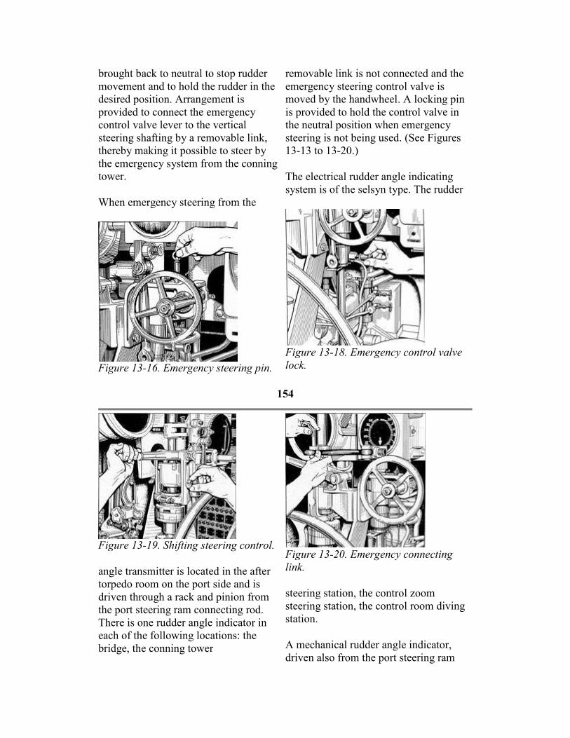
brought back to neutral to stop rudder
movement and to hold the rudder in the
desired position. Arrangement is
provided to connect the emergency
control valve lever to the vertical
steering shafting by a removable link,
thereby making it possible to steer by
the emergency system from the conning
tower.
When emergency steering from the
Figure 13-16. Emergency steering pin.
removable link is not connected and the
emergency steering control valve is
moved by the handwheel. A locking pin
is provided to hold the control valve in
the neutral position when emergency
steering is not being used. (See Figures
13-13 to 13-20.)
The electrical rudder angle indicating
system is of the selsyn type. The rudder
Figure 13-18. Emergency control valve
lock.
154
Figure 13-19. Shifting steering control.
angle transmitter is located in the after
torpedo room on the port side and is
driven through a rack and pinion from
the port steering ram connecting rod.
There is one rudder angle indicator in
each of the following locations: the
bridge, the conning tower
Figure 13-20. Emergency connecting
link.
steering station, the control zoom
steering station, the control room diving
station.
A mechanical rudder angle indicator,
driven also from the port steering ram

connecting rod, is located in the after
torpedo room.
155
14
BOW AND STERN PLANES SYSTEMS
A. INTRODUCTION
14A1. General. Hydraulic power is
used to tilt the bow and stern planes.
Each system (bow and stern planes) has
its own power supply system. Except in
emergencies, the power facilities in
each system are adequate for its own
individual operation without reliance
on power from the main hydraulic
system.
The control units for diving and rising
are assembled in a diving control stand
located in the control room. There is a
set of controls for stern plane tilting, a
set for bow plane tilting, and control
valves for bow plane rigging. The
control panel has diving indicators,
gages, and motor switches.
Three methods of plane tilting are
available at the control panel, based on
three different sources of hydraulic
power. They are designated as follows:
1. Power, in which the power is
independently developed in each plane
tilting system by the motor-driven
Waterbury A-end pump belonging to that
system.
2. Hand, in which the power is developed
in the diving control stand pump,
connected to each system, by the manual
efforts of the diving stand operator.
3. Emergency, in which the power is
obtained from the main hydraulic system.
Emergency is used only when normal
power fails. Hand power is employed
when the other two power sources are,
inoperative, or when silent operation of
the submarine is necessary to avoid
detection by the enemy.
In addition to bow and stern plane tilting,
this chapter also contains a description of
bow plane rigging. A schematic view of
the bow and stern planes systems and
their associated equipment is illustrated
in FigureA-21.
B. BOW AND STERN DIVING GEAR
14B1. Bow planes. Each plane is
carried on a separate stock. The
mechanism for tilting planes consists of
a hydraulic cylinder and piston
arrangement connected by a connecting
rod to the tiller, the latter being
hydraulic pump are the Waterbury type,
size 5 A-end, connected by a flexible
coupling to an electric motor of 7.1 hp at
350 rpm constant speed. These units are
located in the forward and after torpedo
rooms respectively.

mounted on and secured by clamping
and doweling to the hexagonal-shaped
end of each plane stock. The planes are
actuated between stops, allowing a total
travel of 54 degrees of 27 degrees each
side of zero tilt.
14B2. Stern planes. The horizontal
athwartship for the stern diving planes
is keyed to a tiller which is operated
through an angle of 54 degrees by a
connecting rod, cylinder, and piston
arrangement located in the after torpedo
room under the non-watertight walking
flat.
The bow and stern diving gears are of
the electrohydraulic type and under
normal operation the planes are tilted
by power. The
The motor of the electrohydraulic system
is started and stopped by a push button
type switch, and provided with an
electrically operated brake which grips
the armature shaft when the motor is not
being operated. An interlock switch,
controlled by operation of the change
valve at the operating station in the
control room, prevents starting the motor
except when the change valve is in
Power position.
In the control zoom at the operating
station, a handwheel is connected to
another hydraulic pump. (See Figure 14-
1.) Rotating the handwheel with the
change valve set for Power forces oil to
control cylinders at the electrically driven
pump. This actuates the
156
control shaft on the pump by means of
a rocker shaft and bell crank, thereby
controlling the direction of flow and
quantity of oil. Thus, the direction and
amount of tilt are governed by the
rotation of the handwheel of the diving
station; to the right for
Dive and to the left for Rise. The
handwheel should always be brought
back to its original position to stop
further movement of planes; this also
allows the centering device, consisting of
a double-acting spring, to hold the pump
control shaft in its neutral position.
C. OPERATIONS
14C1. Power tilting of planes. When
tilting the bow or stern planes by
power, the change valve for that plane
must be in the power position. The
stroke adjuster is set for one-quarter of
a stroke and the hydraulic pump motor
is started at the diving station. When
the station is set for power tilting,
turning the wheel delivers oil to the
control cylinder which actuates the
tilting box of the power-driven
hydraulic pump. Tilting the box of a
power-driven hydraulic pump causes it
similarly, they are not interconnected and
must be individually operated.
Turning the emergency control valve
handwheel clockwise directs oil from the
main hydraulic system directly to the
stern plane ram in the after torpedo room
and the bow plane rain in the forward
torpedo room. The oil flow will be for
dive. Turning the control valve
handwheel counterclockwise admits oil
to the stern plane ram and the bow plane

to deliver oil to the tilting ram.
When the wheel is turned clockwise, oil
is delivered for dive angle on the
planes; when the wheel is turned
counterclockwise, oil is delivered for
rise angle on the planes. (See FigureA-
22.)
14C2. Hand tilting of planes. In tilting
the bow and stern planes by hand, the
electrohydraulic system is stopped and
the change valve at the diving station is
set for Hand; rotating the handwheel
forces oil directly to the hydraulic
cylinder located in the forward torpedo
room for bow planes, and the after
torpedo room for stern planes.
The bow plane setup is the same as the
stern plane setup for hand tilting except
that the hand rigging and tilting control
valve is used on bow plane tilting to
direct the oil to the rams (FigureA-23)
when set in the tilt position.
14C3. Emergency tilting of planes. Provision is made for tilting the planes
with the main hydraulic system by
setting the change valve at the diving
station in the Emergency position. The
direction of oil flow for tilting the
planes is then controlled by the
emergency control valve.
The bow and stern planes have separate
control valve handwheels for
emergency operation. While the
handwheels operate
ram for rise. (See FigureA-25.)
14C4. Plane angle indicating system. The plane angle indicating system is of
the selsyn type. The bow plane
transmitter is located in the forward
torpedo room and is driven from the
starboard plane stock by a gear segment
and pinion. The stern plane transmitter is
located in the after torpedo room and is
driven by an arrangement of levers and
links from the plane tilting piston rod.
The indicators are mounted on the diving
station panel in the control room, In
addition, an auxiliary plane angle
indicating system is provided which
indicates the degree of rise or dive on the
planes in 5-degree intervals. A
mechanical plane angle indicator is
provided in the forward torpedo room
and two plane angle indicators in the
after torpedo room, one on the after
bulkhead and one at the tilting cylinder
beneath the platform deck.
14C5. Stern diving gear and capstan
motor. The stern plane tilting motor,
located in the after torpedo room, is also
used to operate the after capstan by a
silent chain drive with the sprocket
mounted between the motor and the
hydraulic pump. The chain is removable
and can be dissembled by removing a
special pin from the links. The stern
plane tilting hydraulic pump cannot be
cut out when the capstan is in use;
therefore, the pump control shaft should
be in the neutral position to prevent the
movement of the planes.
157

Figure 14-1. Diving control station
158
14C6. Stern plane drift stop. The
position at which zero lift occurs with
relation to the stern planes is with the
planes set at 4 degrees in the rise,
direction; the position at which
minimum drag occurs is with the
planes set at 2 1/2 degrees in the rise
direction. Therefore, it is desirable that
the indicator in the control room read
zero when the planes are set at 4
degrees in the rise direction, because
in that position the lift, when operating
submerges, is zero. It is also desirable
that when operating on the surface, the
planes be set at that angle at which a
minimum of drag or resistance is
encountered. In order to obtain a
setting of 2 1/2 degrees rise while
control valve to rig. (See FigureA-24.)
Rotating the bow diving handwheel to
the right will rig out the planes. A hand-
operated clutch is provided for windlass
and capstan or plane rigging operation
and is located in the forward torpedo
room. With the clutch set for bow
rigging operation, the hydraulic motor
drives a vertical shaft through a
reduction gear and worm gear
arrangement. This shaft passes through
the hull to the outside where bevel gears
and shafting operate two pairs of 39 1/4-
inch diameter spur gears. These gears
are mounted in pairs athwartships and
fore and aft, so that the forward and
after gear of each pair carry at a point on
the circumference the pin for the crank

operating on the surface, the indicator
in the control room should read 1 1/2-
degree dive.
When cruising on the surface under
normal conditions, a drift stop is
provided to prevent the stern planes
from passing beyond the 2 1/2, degree
rise position. This drift stop is located
at about the midstroke of the end of
the piston rod extension in the after
torpedo room. A bar is provided to be
lifted in the path of the end of the
piston rod extension when the planes
are approaching the 2 1/2-degree rise
position blocking the path and thus
preventing the rod extension from
moving farther in the rise direction.
The planes must be moved in the dive
direction until the indicator (in the
control room) reads at least 5 degrees
dive before the stop bar can be lifted
into position. A pin in the rod
extension enters a hole in the bar as
the planes are moved to the 2 1/2-
degree rise position. The stop bar is
released by moving the planes in the
dive direction until the indicator (in
the control room) reads at least 5
degrees dive, disengaging the pin from
the stop bar and allowing the bar to
drop clear of the path of extension rod.
14C7. Bow plane rigging
arrangement. The bow planes are
rigged out for tilting operation by the
windlass and capstan hydraulic motor,
a Waterbury size 10 B-end normally
driven from the main hydraulic system
through the rigging control valve.
Provision is also made for rigging the
planes by hand from the diving station
by setting the change valve to Hand,
the rigging control valve to Neutral,
and the hand rigging and tilting
end of the plane rigging connecting rod.
The gears are rotated 181 degrees 41"
between mechanical stops when raising
the planes from the horizontal to the
housed position. At the lower end of the
vertical shaft, an indicator switch is
driven by bevel gears; this indicates the
rigged in or rigged out position by
telltale lights at the diving station.
14C8. Rigging and tilting interlocks. At the lower end of this same vertical
shaft, the rigging interlock switch,
driven by bevel gears, prevents the
operation of the electrohydraulic bow
plane tilting motor except when the
planes are in the fully rigged-out
position. There is also a hydraulic
interlock valve which prevents the flow
of oil to the plane tilting cylinder from
the hand or emergency control valve
until the planes are in the fully rigged-
out position. The operating mechanism
for this interlock valve is also driven by
bevel gears from the vertical shaft, and
the bow plane rigging indicator is
mounted on the underside of the casing.
If the sheer pin drive at the lower end of
the pointer shaft fails, the interlock
valve may be operated by applying the
T-handled socket wrench to the squared
lower end of the shaft extending through
the pointer hub. This wrench is stowed
on the underside of the worm gear unit
adjacent to the valve operating
mechanism.
In addition, there is also a regulating
control valve operated from the same
shaft. The purpose of this valve is to
restrict the flow of oil to the hydraulic
motor when the

159
bow planes are nearly rigged out or
nearly housed. The flow is not
completely cut off; a small amount is
bypassed to permit the planes to creep
into the stops located on the large spur
gears. There is also a lock on the
rigging control valve operated by a
solenoid; this prevents the housing of
the bow planes unless the planes are
within 1 1/2 degrees either side of zero
tilt, and then only by manually
operating the push button which
releases the lock. An additional release
of the solenoid lock is also provided
for emergency use and is
accomplished by means of a lever
located in the armature end of the
solenoid. This means of disengaging
the solenoid lock should be used for
rigging out planes only in
case they have been thrown off the
position for rigging as a result of wave
slap.
The diving gear control stations, bow
and stern, are located together on the
port side of the control room. (See
Figure 14-1.) They are provided with an
8 1/2-inch depth gage reading to 450
feet and a rudder angle indicator. Each
station is provided with an electrical
self-illuminated selsyn type plane angle
indicator, an auxiliary plane angle
indicator reading at 5-degree intervals, a
16-inch depth gage reading to 165 feet,
and a pair of spirit trim indicator
inclinometers for angles from 0 degrees
to 5 degrees and from 0 degrees to 15
degrees.
160
15
ANCHOR HANDLING
GEAR AND CAPSTANS
A. ANCHOR HANDLING GEAR
15A1. General. The ground tackle
consists of one 2,200-pound stockless
anchor and 105 fathoms of 1-inch die-
lock steel chain. The anchor is housed
in the hawsepipe in the superstructure.
The anchor chain is self-stowing in the
chain locker.
The windlass consists of a wildcat
driven by a hydraulic motor, which also
drives the forward capstan (FigureA-
26). The motor is a Waterbury size 10
B-end, and is operated from the main
fair-lead upon which are mounted two
jaws operated by two traveling nuts on a
screw to act as a chain stopper for
securing the chain. The chain stopper is
operated by gears and shafting from the
main deck. An indicator is provided at
this station and is operated from the drive
gear casing for the chain stopper
operating shaft.
The bitter end of the anchor chain is
secured in a tumbling hook just above the
top of the chain locker and is unlocked
hydraulic system.
The hydraulic motor drives a worm
gear, located overhead, which in turn
drives a vertical shaft passing through
the hull.
The windlass and capstan clutch,
located in the drive gear casing at the
upper end of the vertical shaft, is
operated from the main deck, an
indicator being fitted at this station. A
pair of spur gears in the drive gear
casing drive the vertical shaft on which
the capstan head is mounted at the main
deck. A pair of bevel gears drive the
shaft, which goes forward to a bevel
gear assembly. This assembly is
mounted on the windlass which
actuates the wildcat drive shaft, from
which a spur pinion drives the spur gear
on the wildcat casting.
A chain indicator, reading in fathoms,
is provided on the main deck. Windlass
and capstan cannot be driven at the
same time.
The wildcat carries a snubber brake
band which is operated by gears and a
line of shafting to the main deck. An
indicator is fitted at this station.
The anchor chain, upon leaving the
chain locker, passes through a closed
from the main deck. The latch, which
releases the hook, is attached by means
of a long connecting rod to a crank on the
operating shaft, located beneath a small
hatch in the deck on the port side, about
15 inches from the centerline of the ship,
where a wrench provided for operating
the chain slip is stowed in a convenient
place. The operating shaft is locked in the
normal secured position of the tumbling
hook by a hinged locking plate which
engages the square end of the operating
shaft. The locking plate is held in
position by a toggle pin. The anchor
chain can be slipped only when the
vessel is on the surface.
Hand operation of the windlass from the
diving station is accomplished by setting
the change valve to HAND, and the
rigging control valve to NEUTRAL, the
hand rigging and tilting control valve to
RIG, and the clutch in the forward
torpedo room in windlass and capstan
position. Rotating the bow diving
handwheel to the right will hoist the
anchor.
B. CAPSTANS
15B1. General. Two capstans are
provided on the main deck, one
between frames 20 and 21 and the other
between frames 117 and 118. Both are
permanent fixtures mounted on vertical
shafts. The capstan heads are 15 inches
in diameter for a rope speed of 60 feet
per minute.
The forward capstan is driven by a
hydraulic motor. (See FigureA-26.) The
capstan head is removable and when not
in use

161
can be stowed below the main deck on
the port side adjacent to the capstan
shaft.
The after capstan is driven by the stern
plane tilting motor through a chain
drive from a sprocket on the after end
of the motor shaft to the capstan worm
gear. The chain is removable and can
be disassembled by
removing a special pin from the links.
The stern plane tilting hydraulic pump
cannot be cut when the capstan is in use;
therefore, the pump control shaft should
be in the neutral position to prevent
movement of the planes. The capstan is
mounted on the top of the vertical worm
gear shaft.
C. OPERATIONS
15C1. Dropping the anchor from the
water's edge. Following is the
procedure for dropping the anchor from
the water's edge:
1. Shift the clutch in the forward
torpedo room to the windless and
capstan position.
2. Shift the clutch on the main deck
to the windless position.
3. Open the chain stopper.
4. Loosen the brake band.
5. Operate the windlass and capstan
control valve from the main deck by
turning counterclockwise to lower.
6. When the anchor reaches the
water's edge, return the windlass and
capstan and anchor control valve to the
neutral position.
7. Tighten the brake band.
8. Put the windlass and capstan
clutch on the main deck in the neutral
position.
9. Release the brake band.
Note. When the brake band is released,
the weight of the anchor will carry out
the chain. The chain is snubbed when
the desired length is run out.
15C2. Hoisting the anchor by hand. Hoisting the anchor by hand is
accomplished as follows:
1. Shift the change valve in the
control room at the bow plane diving
station to the hand position.
2. Set the bow plane tilting stand
pump stroke to full stroke.
3. Set the hand rigging and tilting
control valve to the rig position.
4. Shift the clutch in the forward
torpedo room to the windlass and
capstan position.
5. Shift the clutch on the main deck to
the windlass position.
6. Loosen the brake band.
7. Open the chain stopper.
8. Rotate the bow plane wheel
clockwise to raise the anchor.
15C3. Securing the anchor for sea. In
securing the anchor for sea, it is
necessary to:
1. Shut the chain stopper.
2. Tighten the brake band.
3. Shift the clutch on the main deck to
the windless position.
162

16
FUEL AND LUBRICATING OIL SYSTEMS
A. FUEL OIL SYSTEM
16A1. General description. All fuel
oil stowage tanks lie between the inner
and outer hulls. There are four normal
fuel oil tanks No. 1, frames 35-41; No.
2, frames 41-46; No. 6, frames 93-99;
No. 7, frames 99-107. There are six
reserve fuel oil tanks: No. 3A, frames
57-62 starboard; No. 3B, frames 57-62
port; No. 4A, frames 69-75 starboard;
No. 4B, frames 69-75 port; No. 5A,
frames 75-80 starboard; and No. 5B,
frames 75-80 port. (See FigureA-7.)
These six reserve fuel oil tanks make
up the fuel ballast tank group.
Each tank is connected to three piping
systems: the fuel oil filling and transfer;
the compensating water; and the 225-
pound service air system. The 3-inch
filling and transfer main, with a main
deck filling connection at frame 33 and
another at frame 69, has two branches
to each fuel oil tank, one for each side
of the tank. The 3-inch compensating
water main, with a deck hose
connection at frame 88 and an outlet
through a head box, has a branch to the
bottom of each fuel oil tank. (See
FigureA-27.)
Between frames 91 and 93, there are
two tanks: the expansion tank on the
port side and the collecting tank on the
starboard side. Located in the conning
tower sheers is a head box with a vent
and overflow which is kept filled with
water from the main engine circulating
water system. A 3-inch line carries the
water from the head box to the bottom
of the expansion tank. Another line is
run from the top of the expansion tank
The 3-inch fuel filling and transfer main
has a branch to the bottom of the
collecting tank, and another line is run
from the top of this tank to the engine
clean fuel oil tank. Hence, water under
pressure from the head box passes
through the expansion tank, to the
compensating main, and them to the fuel
oil tank being used as the supply. From
the supply tank, oil flows through the
transfer main to the collecting tank and
on to the clean fuel oil tank. The stop
valve in the collecting tank supply from
the 3-inch transfer main is locked open;
so locked, valves provide for transfer and
compensation under all conditions of
operations when a tank, either normal or
reserve, is open to the transfer main. A
supply tank must always be open to the
filling and transfer main, otherwise the
collecting tank is subjected to the depth
pressure when submerged.
Filling operations are effected through
the forward and after deck connections
described above. The head of oil forces
the water overboard through the deck
hose connection for the compensating
main or through the expansion tank and
head box.
In case of damage to the head box,
pressure is kept on the compensating
system by a line to the compensating
main from the main motor circulating
water system in the motor room. Normal
operation requires that the stop valve in
this line be locked shut. This practice of
locking the stop valve during normal
operation assures that the compensating
system will operate without drawing

to the 3-inch compensating water main.
These two lines and all branches off the
main are provided with stop valves.
Each one of these stop valves, except
for the hose connection, is kept locked
in the open position. The head of water
keeps the tanks completely filled at all
times. Thus provision is made for the
change in volume caused by the
variation in temperature and also for
changes in pressure, so that the tank is
always equalized with sea pressure
when submerging.
water from the main motor circulating
water system. On the surface, the main
engine circulating water system is
sufficient to keep the head box full, thus
maintaining a constant pressure on the
expansion tank and from it to the fuel oil
tank on service and the collecting tank.
Fuel oil leaving the collecting tank under
the compensating system pressure may
either go to the purifier and from there by
gravity to CFOT, or it stay go to the fuel
transfer and purifier pump. The fuel
163

Figure 16-1. Fuel transfer and purifier pump.
164
transfer purifier pump discharges fuel
oil to the main engines. The pump may
therefore serve as a standby for the
main engine fuel pump since the fuel
transfer purifier pumps can take a
suction on the line from the collecting
tank to the purifier; the transfer main
and the CFOT discharge this oil
directly to the main engines. The fuel
transfer purifier pumps may also
discharge directly overboard. Purifying
drain pump is provided with a discharge
to the compensating water main to permit
pumping the bilges to the top of the
expansion tank, forcing water overboard
from the bottom of the tank. This
removes the necessity of discharging
bilge water directly overboard.
Valves are provided on the branches
from the transfer main to the deck filling
connections for obtaining samples of the

is not normally done submerged.
However, if it is, the depth pressure
will maintain a constant pressure on the
compensating system.
There are two fuel transfer and purifier
pumps: one in the forward engine
room, supplying clean fuel oil tank No.
1, and one in the after engine room,
supplying clean fuel oil tank No. 2.
The fuel pump is the positive
displacement gear type. A d.c. motor of
1 horsepower furnishes the driving
power at 1150 rpm operating speed.
This pump has a capacity of 10 gallons
per minute.
The operating parts include the valve
body, the rotor and idler, and the relief
valve which is set to open at 45 psi.
(See Figure 16-1.)
A bypass line is provided from the
transfer main to the fuel transfer and
purifier pump for use in the event of
bilging the collecting tank. Also, a
branch from the head box is run to the
compensating main so that the
expansion tank may be bypassed. The
stop valve in each of these lines is
normally locked shut.
The collecting tank is provided with a
drain line to the drain pump for the
removal of water from the bottom of
the tank. The
oil. Fuel tanks are provided with a blow
and vent manifold, with blow and vent
connections to each side of the tank from
the manifold. The manifold is provided
with gages and relief valves set at 15 psi.
When blowing a fuel tank, water must
leave the tank through the compensating
water main. Balanced hydraulic gages
(liquidometers) are installed in the
expansion, collecting, and clean fuel oil
tanks to indicate the oil content.
The connection from the compensating.
water line to the compensating water
manifold and to the head box is provided
with a sight glass to check the pipe
contents when filling, blowing, and
pumping operations are being conducted.
The fuel oil tanks and the compensating
water line should be vented frequently to
prevent formation of air pockets. Filed
oil tanks should be vented in the
following order expansion tank, fuel oil
tank or tanks in use, collecting tank. The
discharge from collecting tank to clean
fuel oil tank should be shut when
venting.
It is essential that all air be excluded
from the fuel oil system, as fuel will not
readily flow past an air pocket under the
small head pressure provided by the head
box.
B. RESERVE FUEL OIL TANKS
16B1. General. Fuel ballast tanks Nos.
3A, 3B, 4A, 4B, 5A, and 5B may be
used either as ballast tanks or as reserve
fuel oil tanks. When used for reserve
fuel oil tanks, the fuel ballast tanks
must be isolated from the 600-pound
and the flood valves to these tanks locked
shut. This prevents either the compressed
air or the sea water from entering the
tanks and interfering with the proper
operation. of the fuel oil system.

main ballast tank blowing system, and
the 10-pound main ballast tank blowing
system. All the blow valves leading to
these tanks from both the 600-pound
and the 10-pound blowing manifolds
must be secured,
The main and emergency vent valves to
the fuel ballast tanks must also be
secured.
Each of the fuel ballast tanks is provided
with one vent valve. Blank flanges are
provided for the valve openings in the
reserve
165
Figure 16-2. Lubricating oil purifier.

166
fuel oil tanks and are to be installed
when fuel is carried in the tank. These
blank flanges are stowed in the
superstructure, adjacent to the vent
valves, and the gasket used with the
blank flange is stowed in the ship.
To attach the blank flange, proceed as
follows: Open the vent valve a slight
amount to relieve the tension on the
spring mechanism. Remove nuts, tap
bolts, and distance pieces from studs in
the finished face on the outside of the
valve openings. Remove the pin
through the lower end of the bellcrank
and connecting link and put the gasket in
place over the studs. Attach the blank
flanges in place over the studs and
replace the nuts and tap bolts and set up
to make a tight joint. Put the distance
pieces in a bag, label them, and stow in
ship. After the blank flanges are in place,
return the operating mechanism to the
locked shut position.
The emergency vent valves for the
reserve fuel oil tanks are provided with
padlocks. When fuel is being carried in
these tanks, the emergency vents will be
locked shut.
C. LUBRICATING OIL SYSTEM
16C1. General. There are three normal
lubricating oil tanks: No. 1 between
frames 79-85, No. 2 between frames
90-96, and No. 3 between frames 107-
109. One reserve lubricating oil tank is
located between frames 76-77 port.
There are four main engine sump tanks:
No. 1 between frames 80-85 starboard,
No. 2 between frames 80-85 port, No. 3
between frames 91-96 starboard, and
No. 4 between frames 91-96 port.
There are two reduction gear sump
tanks: No. 1 between frames 103-105
starboard, and No. 2 between frames
103-105 port.
A filling connection is provided on the
main deck between frames 78-79 port;
it is connected by a 2-inch line to a
four-valve lubricating oil filling and
transfer manifold located at frames 78-
80 starboard. This manifold is
connected directly to each of the
normal lubricating oil tanks and reserve
lubricating oil tanks.
An accessory to the lubricating oil
system is the lubricating oil purifying and
flushing system. The principal part of
this system is the lubricating oil purifier
(See Figure 16-2.), used to separate
impurities from the lubricating oil. There
are two lubricating oil purifiers: one
located in the forward engine room
amidships and the other in the starboard
forward end of the after engine room.
The major part of the lubricating oil
purifier is a hollow cylindrical rotor
called the bowl, the top part of which is
connected by a coupling nut to a spindle,
which in turn is attached to and
suspended from a ball bearing assembly.
Three flat plate wings are spaced radially
equidistant inside the bowl. This three-
plate assembly has a cone on the bottom
with which the feed jet comes in contact,
thus increasing the liquid flow evenly
and eliminating emulsion formation.
The spindle is belt-driven by an electric
motor fastened on the back of the frame.
The belt tension is maintained by an idler

The tanks are normally filled by
passing the oil through a strainer before
it reaches the manifold; however, this
strainer may be bypassed. The
lubricating oil tanks are provided with a
blow and vent manifold with blow and
vent connections from the manifold to
each tank. Air is furnished from the
225-pound service air lines through a
reducing valve set for 13 psi and a
relief valve set for 15 psi. Oil may be
blown from any storage tank to any
other tank; also, oil to be discharged
may be blown or pumped overboard
through the deck filling connection or
through a 1 1/2-inch hose connection
from the filling line.
pulley to assure smooth acceleration.
When the pump is running, the liquid is
jetted into the bowl and, upon coming in
contact with the three flat plates, is
rotated at the speed of the bowl. This
rapid rotation causes centrifugal force to
act on the liquid, thus separating the
heavier from the lighter components in
the liquid. Solids, sludge, and water (the
heavier parts) are forced through the oil
layer to the outside where they form a
layer on the wall of the bowl.
As the oil in a purified condition reaches
the overflow or discharge port, it is
carried
167
Figure 16-3. Fuel oil system.
to the lubricating oil pump and
distributed to the engines.
which also serves as the fuel oil purifier
just described. The machine is set up as

The lower end of the bowl is set in a
guide bushing which shifts in
accordance with the position required
by the center rotation of the bowl.
The lubricating oil purifying and
flushing system may be used to
perform the following functions:
1. Flush engines prior to starting.
2. Purify the lubricating oil.
3. Supply engines with lubricating oil.
4. Clarify the lubricating oil.
Clarification of the lubricating oil is
accomplished by the Sharples
centrifuge
a clarifier by installing a clarifier sleeve
or ring dam on the top of the bowl, thus
closing the outlet passage through which
the water is discharged. The term
clarifier is applied to the machine when
it is set up to discharge a single liquid
from which solid matter has been
removed by centrifugal force. If the
machine is set up to separate two liquids
from solid matter and from each other
(such as oil and water in a fuel oil
purifier), it is called a separator. The
machine is usually set up as a separator
for fuel oil purification and a clarifier
for lubricating oil purification.
169
17
GENERAL SURFACE OPERATIONS
A. OFFICER OF THE DECK
17A1. Duties and responsibilities. Surface operation requires that a
submarine be maintained in a constant
state of readiness, prepared at all times
for any emergency. The safety of the
ship is the responsibility of the officer
of the deck, subject to any orders he
may receive from the commanding
officer. The manner in which the
officer of the deck should carry out his
duties is fully described in United
States Navy Regulations and the Watch
Officer's Guide. However, the unusual
features of a submarine, which directly
affect the officer of the deck, make it
imperative that emphasis be given those
points that are peculiar to this type of
vessel.
securing of all loose gear both topside
and below. Superstructure access
openings must be locked or welded
closed, in anticipation of the most
extreme conditions, to prevent accidental
release of gear and consequent indication
of the submarine's position, and all
external air and oil leaks must be
eliminated. Bow and stern tubes must be
loaded with torpedoes ready to fire and
with one complete set prepared for reload
without further adjustment. All guns and
ammunition must be maintained in the
most advanced state of readiness
compatible with their preservation in
event of quick dives.
17A4. Vulnerability of ship. The

17A2. Desirable characteristics. Desirable qualities of a submarine's
officer of the deck are forehandedness,
vigilance, leadership, and common
sense. Each of these qualities must be
developed to a high degree of
perfection to insure the successful
execution of duties. The officer of the
deck's ability to look ahead and foresee
the development of unusual
contingencies places him in a position
of always being prepared. On
submarines, more so than on other
types of vessels, it is axiomatic that
eternal vigilance is the price of safety.
Alert to all that is going on about him,
he must see everything and know all
that is happening. Conducting himself
in a manner befitting his position, as
representing the commanding officer,
requires a marked degree of leadership.
To this extent he must be exemplary in
his appearance and performance of duty
so that a feeling of confidence and
pride is developed in his subordinates.
The underlying attribute of all these
characteristics of the proficient
submarine officer of the deck is
common sense-a sense of proportion,
the ability to evaluate the components
of a situation in the light of their real
significance.
17A3. Preparing the ship. Preparation
must be completed before leaving port
to place the submarine in a rigged-for-
dive condition. The officer of the deck
supervises the stowing and
officer- of the deck must have a more
intimate technical knowledge of all
departments of a submarine than is
required in surface ships, because a
submarine on the surface is the most
vulnerable type of craft afloat. The
danger of collision exists on a submarine
long before that condition is considered
to exist on a surface vessel; therefore, the
safety of the submarine must never be
jeopardized by unnecessarily placing it in
a position in which collision with another
vessel is possible. Low reserve buoyancy
magnifies the danger resulting from any
collision, requiring the submarine to be
kept well clear of all vessels. Things
happen quickly in submarines, requiring
quick thinking and decisive action to
grasp the opportunity to prevent disaster.
Taking halfway measures may lose the
ship.
17A5. Watch officer's station. The
forward bridge structure is the usual
station of the officer of the deck when on
the surface. Although he is expected to
remain intensely alert and observant, he
is not a lookout, and must not become
engrossed in details to the exclusion of
his comprehensive duties as supervisor of
the watch. The poor habitability of the
bridge and the exacting requirements of
the duties impose strict demands upon
the assigned personnel. The officer about
to relieve the deck should be properly
clothed and physically ft to assume the
responsibilities
170
that will be his. For similar reasons,
lookouts should be selected from the
best men of the crew suitable for this
He must insist that acknowledgement of
directives be made in standard
phraseology, permitting no deviations

duty, and only those chosen who have
excellent vision and good health. Prior
to their coming on the bridge, clothing
should be issued to enable them to
withstand the rigors of adverse climatic
conditions, Cold, wet personnel cannot
function as efficiently as those who are
protected from the weather, in so far as
conditions will permit. The night
lookout should be properly dark-
adapted, wearing red goggles, before
relieving.
17A6. Conduct of the watch. The
officer of the deck must take over his
watch promptly, and be sure to obtain
accurately all the information from the
officer about to be relieved.
He should determine the ship's position
with regard to other ships in sight, the
proximity of land, rocks, shoals, and
the identity of lights. He should always
time navigational lights used in fixing
the ship's position even though they
have been previously sighted and
identified. He must keep the ship's
position plotted on the chart at all
times. He must closely observe the
weather, course, speed, and know the
combinations of propulsion equipment
available. He must know whether or not
the storage batteries are being charged
and how much float is being carried.
He should insure that battery
ventilation is adequate.
He should maintain an efficient watch
by rotating the lookouts. He should
stagger the reliefs, allowing only one
man of the oncoming watch on the
bridge at a time and he should require
"permission to come on the bridge" in
each case, and caution against all
extraneous noise and unnecessary
conversation. Orders should be worded
whatsoever.
The success of night attacks depends
greatly upon the alertness and reliability
of the lookouts. Each should be trained to
know what to look for, carefully
searching his assigned sector, and
reporting his findings in the proper
phraseology. When an unidentified or
enemy vessel is sighted, the officer of the
deck should be so familiar with the
commanding officer's attack doctrine that
he can take the proper action while
calling the crew to battle stations. In
submitting reports to the commanding
officer, he must be certain that the data
are correct, with any doubtful details so
identified. He should develop a
reputation for reliability and integrity. He
must be sufficiently familiar with signals
to be able to determine when another
ship is calling without having to call for
the quartermaster every time flashing
lights are seen.
The officer of the deck must have full
information of the status of every
department of the ship at all times. He
must have knowledge of the condition of
all hull openings, ballast tanks, flood
valves, vents, variable tanks, pumps, and
so forth. Particular attention must be
given to the ship's readiness to dive,
permitting nothing to jeopardize this
condition without the commanding
officer's permission. As soon as charts,
sextants, and other loose gear are no
longer in use, or the necessity of
additional personnel on the bridge has
ceased to exist, he should see that the
ship is returned to a condition in which
she is able to dive without delay.
Appropriate consideration should be
given the fact that submarines have a
small freeboard, resulting in danger of
personnel being washed overboard or

in standard phraseology, and given in
an authoritative manner only as loud as
the occasion demands.
water entering the ship through
ventilation and deck openings.
B. SHIP HANDLING
17B1. Experience. The mere reading
of a book will not establish perfection
in the art of ship handling, an
accomplishment attained only by
practice, and more practice, in
performing the actual operations.
Nevertheless. the printed page provides
a means of
perpetuating the findings and advice of
those who have learned by experience.
Above all, ship handling demands good
judgment. Existing and anticipated
situations must be carefully considered
before action is taken. The officer of the
deck should
171
handle the ship smartly, and he should
always remember that in coming
alongside a dock or another ship, a
submarine holds her way longer than a
surface ship of similar tonnage.
17B2. Control. Steering and engine
control are, at all times, from the
conning tower or control room, in
which are located the power,
emergency, and hand steering controls.
The officer of the deck should practice
the use of the two latter systems, except
when maneuvering in restricted water's,
thereby training. the steersmen and
testing the equipment for emergency
operation. In a submarine, more so than
in other types of vessels, good
judgment demands that all machinery
be tested prior to its prospective use.
Hand steering trains steersmen to use
small amounts of rudder, and permits
more nearly silent operation.
Control is temporarily poor when
shifting from conning tower to control
room, and when shifting from engines
to motors. If a doubtful situation exists
at these times, prudence dictates
their direction of rotation should be
thought out carefully. Quite often the
backing of both propellers would spoil an
otherwise good landing, where the
situation demanded that one, or the other,
should be backed.
17B4. Current effect. Accurate
estimation of the strength and direction
of current is essential to the success of
the maneuver. This is easily estimated by
noticing a spar buoy, or watching the
water flow past the end of a dock. The
current must not only be considered
when selecting the turning point while in
the channel but it must be remembered
after the turn, realizing that the slower
the vessel approaches the dock, the
greater will be the effect of the current.
Similarly, it is important to remember
that after the bow enters the slip, it is in
relatively still water, while the current
continues to produce its full effect on the
stern.
17B5. Wind effect. A submarine making
sternboard will back into the wind,
because of the greater freeboard of the
bow, making it difficult to turn in a

maintaining the status quo until
circumstances permit a change, When
operating on the surface, enough way
should be kept on the ship to permit
maneuvering or quick diving.
17B3. Landings. When maneuvering
around docks and other close quarters,
especially at night, the officer of the
deck must assure himself of
unobstructed visibility in all directions.
He should carefully plan the approach
to the landing, with special reference to
current, wind, amount of way on,
turning points, sea room available in
the slip, and the preparation of lines.
The use of excessive speed is both
dangerous and inexcusable; a
submarine is not equipped with four-
wheel brakes.
He should never bump any part of the
submarine-the underwater bow and
stern parts are especially vulnerable,
Landings should be made gently.
Landing should be a precisely executed
maneuver, so planned and performed
that the simple operation of backing
one or both propellers for a few
seconds, when near the desired
position, will take all, or nearly all, way
off the ship and leave her practically in
her berth, ready to double up all lines.
The choice of screws and
narrow channel or maneuver alongside a
dock. Like all propeller-driven surface
ships, a submarine rides more easily with
her quarter to the wind and Sea .
Possible hull distortion, and damage to
bow tube shutters, diving planes,
superstructure, and bridge strongly
indicate that the submarine should not be
pounded into heavy seas unless
absolutely necessary.
17B6. Turning. In making a turn in a
narrow channel, the ship may be turned
on her heel by going ahead slowly on one
propeller while backing full on the other,
with rudder over in the direction of turn
to assist the ahead screw. This forward
and reverse combination of the screws
may also be helpful in getting the stern in
to the dock, Before backing on one or
both propellers, the rudder should be
used to steady, or start, a desired swing,
as conditions may warrant. If the vessel
is swinging, the backing of the inboard
screw will normally accelerate the swing.
17B7. Backing.Special signals and exact
procedure for backing must be
established for emergency use in the
event of failure of
172
usual engine signals. Before backing,
the officer of the deck should see that
all is clear, and guard the stern planes
and propeller while proceeding out of
the berth. The stern should be placed
well clear of the dock by holding a
forward spring, while going ahead for a
few seconds on the outboard screw. A
strong dock will permit winding around
intelligently. The men at the lines should
not be expected to do the thinking for the
officer of the deck. These mooring
operations should be directed just as
actively and positively as signaling the
engines. One satisfactory method of
getting the ship alongside the dock
against the tide is by securing a breast
line from the bow to the dock. Then, with

the end, after the stern is clear.
17B8. Handling lines. In approaching
the dock, the mooring lines should be
handled
the rudder outboard, the outboard
propeller should be backed while going
ahead on the inboard screw.
C. STANDARD PHRASEOLOGY
17C1. Getting underway. a. "Station the maneuvering watch."
Personnel man their stations in
accordance with the Watch, Quarter,
and Station bill. Start and test
machinery. Special details such as line
handlers, anchor detail, color detail,
and leadsman take their stations.
b. "Stand by to answer bells." A
preparatory command to the watch,
indicating that orders to the engines
will follow directly.
c. "Station the regular sea detail."
An order given when clear of restricted
waters and the special details of the
maneuvering watch are no longer
required.
17C2. Line handling. a. "Stand by the lines." Man the
lines, ready to cast off or get the lines
over to the dock.
b. "Cast off number one." Release
number one line from the dock.
c. "Ease four." Pay out enough of
the designated line to remove most of
the strain.
d. "Hold three." Take enough turns
so that the designated line will not give.
e. "Check two." Hold, but let it run
when necessary so that it will not part.
f, "Take a strain on four." Put the
line under tension.
g. "Get over number one." Heave
number one line to the dock.
h. "Take three up the dock." Man
ashore receiving the line takes it up the
dock to a new position.
lines." Pull the lines, released from the
dock, aboard.
k. "Single up." Bring up double lines
so that only single parts remain secured.
l. "Double up and secure." Run
additional lines and double them as
necessary to secure the mooring.
m. "Slack one (two)." Pay out the line,
allowing it to form an easy bight.
17C3. Orders to the wheel. a. "Right (Left) rudder." A command
to give her right (or left) rudder instantly,
an indeterminate amount. In all such
cases, the officer conning the ship should
accompany the order with a statement of
his motive, or the object to be attained, so
that the steersman may execute the order
with intelligence and judgment,
b. "Right (Left) full rudder." A
maximum rudder angle of about 35
degrees is used in the Navy.
c. "Right (Left) standard rudder." Not
used on submarines.
d. "Right (Left) standard half rudder."
Not used on submarines.
e. "Right (Left), 5 (10, etc.) degrees
rudder." These orders are used in making
changes of course. All courses given to
the steersman must be compass courses.
f. "Right (Left), handsomely." This
order is given when a very slight change
of course is desired.
g. "Give her more rudder." Increase
the rudder angle already on to make her
turn more rapidly.
h. "Ease the rudder." Decrease the
rudder angle already on when she is
i. "Take in the slack on four." Heave
on line and hold it taut, but do not take
a strain.
j. "Take in two." or "Take in the
after
turning
173
too rapidly, or is coming to the heading
desired. The order can be given, "Ease
to 15 (10, 5, etc.)."
i. "Rudder amidships." Rudder is
centered and kept there until the next
order.
j, "Meet her." Use rudder as may be
necessary to check, but not entirely stop
her swing.
k. "Steady," or "Steady so," or
"Steady as you go." Steer the course on
which the ship is heading when the
command is received.
l. "Shift the rudder." Change from
right to left rudder, or vice versa.
m. "Mind your rudder." A warning
to the quartermaster (or steersman) 1)
to exact more careful steering, or 2) to
put him on the alert for the next
command to the wheel.
n. "Mind your right (left) rudder." A
warning that the ship shows a frequent
tendency to get off her course, and that
if right (or left) rudder is not applied
from time to time to counteract this
tendency, the ship will not make good
the course set.
o. "Nothing to the right (left)."
Given when the course to be made
good is a shade off the compass card
mark, and therefore meaning that all
small variations from the course in
steering must be kept, for example to
the southward of the course set.
p. "Keep her so." A command to the
steersman when he reports her heading,
and it is desired to steady her.
q. "Very well." Given to the
steersman, after a report by him, to let
him know that the situation is
understood. The expression "All right"
should not be used, it might be taken as
an order to the wheel.
17C4. Orders for the engines. Standard
orders to the engines are given in three
parts: 1) the first part designates the
engine starboard, port, or all; 2) the
second part indicates the direction: ahead
or back; and 3) the third part indicates
the speed: 1/3, 2/3, standard, full, flank,
or stop.
Typical orders are:
1. "Port, ahead, 2/3."
2. "Starboard, back, full."
3. "All, ahead, standard."
4. "Port, back, 1/3; Starboard, ahead,
2/3."
5. "All, stop."
In the submarine service, the word
engine is omitted in orders to the engines
or motors, to eliminate confusion
resulting from the fact that under various
conditions, and with various types of
main drive, engines sometimes deliver
the power, and motors sometimes do.
174
18
GENERAL DIVING OPERATIONS
A. SUBMERGING
18A1. General. A submarine, when on
the surface, must be in readiness to dive
at any time. This requires the vessel to
be maintained constantly in diving trim
so that little or no trim adjustment is
necessary after submergence. The ship
is rigged for dive immediately after
getting underway, in strict.
conformance with the check-off list
posted in each compartment.
18A2. Types of dives . Three types of
dives are possible: 1) the quick dive, 2)
the running dive, and 3) the stationary
dive, the choice being dictated by
existing conditions. In all dives the ship
is placed in the condition of neutral or
negative buoyancy; the use of negative
buoyancy shortens the diving time.
A quick dive is made when the ship is
underway on one or more main
engines. The bow planers are placed on
FULL DIVE and the forward speed
results in a maximum downward thrust
on the bow planes. As the submarine
submerges, the upper surfaces of the
hull and superstructure act as planing
surfaces and increase the downward
thrust. The quick dive is the fastest of
the three types and is used in
acceptance trials of new submarines,
when it must be executed within 60
seconds from standard diving trim.
A running dive is performed in the
same manner in a minimum time, the
only difference being that surface
propulsion, at the beginning of the dive,
is by battery-powered main motors.
18A3. Control station. The necessary
instruments and equipment for
submergence and control of the boat
while submerged are located in the
control room. The control room is the
station of the diving officer who issues
the necessary orders during a dive and
directs the men at the manifolds, pumps,
and diving gear in maintaining the
submarine at the desired depth. An
illustration of the control station is shown
in Figure 14-1.
The control station includes the bow and
stern planesmen's stations and is
equipped as follows:
a. Depth gage, reading from 0 to 165
feet, indicates the keel depth,
b. Inclinometers indicate the angle of the
vessel's longitudinal axis with the
horizontal.
c. The plane angle indicators are
miniature diving planes, the trailing
edges of which range over degree scales
and indicate the angle of rise or dive on
the bow and stern planes.
d. A motor control contact-type switch.
provides selection of direction of rotation
of plane-tilting motor in those
installations using electrically operated
planes. Hydraulically operated planes are
controlled by a two-way valve.
e. The selector switch provides a choice
of motors on which the controller is to be
used. The bow planes may be rigged or
tilted according to the position of the

A stationary dive is made when the
ship is dead in the water. The main
ballast tanks are completely flooded
and enough water is flooded into the
variable ballast tanks to destroy the
remaining positive buoyancy. Flooding
and pumping may be alternated to
maintain the ship on an even keel at
any desired depth. This type of dive is
sometimes used during builder's trials
to test and inspect the hull at various
submerged depths down to final test
depth.
switch handle. A similar device at the
stern plane controller provides for use at
the stern plane motor to operate the after
capstan.
f. The hand-operated clutch, on electric
drive, permits shifting from power to
brand operation of planes. Hydraulically
operated planes are controlled by a valve
which, when placed in the neutral
position, permits manual drive direct to
the planes.
g. A depth gage reading from 0 to 600
feet, mounted at the center of the control
panel, is visible both to planesmen and
the diving officer.
175
h. The rudder angle indicator,
graduated in degrees, indicates the
amount of left or right rudder on the
ship.
i. The aneroid barometer indicates the
air pressure in the ship.
j. The hull opening indicator light
panel, commonly referred to as the
Christmas tree (Figure 18-1), indicates
the condition of hull openings, vents
and flood valves. Electrical contacts at
these various openings and valves
operate red and green lights in the
panel. A green board shows that all hull
openings are closed.
18A4. Rig for dive . Before an actual
dive is undertaken, the submarine must
be fully prepared. Compensation must
have been made for all changes in
weight since the last dive, and all hull
openings, except those necessary for
the operation of the ship on the surface,
must be closed. The hull openings not
c. The main engine induction outboard
valve which admits air to the engines.
d. The forward and after engine room
induction hull flappers which admit air to
both forward and after engine rooms.
The safety and negative tanks are flooded
and the flood valves left open. All
bulkhead watertight doors and bulkhead
flappers are checked for free operation.
Outboard battery ventilation exhaust
valves, if installed, are closed and
checked by sighting the valve disc and by
checking the mechanical indicator.
Sufficient high pressure air, at least 45
percent of total capacity, must be cut into
the manifold. Rapid and efficient
communication must be established
between the diving officer and all
compartments.
All of these details must be checked by
one or more officers. When the diving
officer is informed that all preparations
are completed, he reports to the

closed, and the reasons therefore, are as
follows:
a. Conning tower hatch which provides
passage to or from the bridge.
b. The hull ventilation supply valve
which remains open to permit the
circulation of fresh air.
commanding officer, "Ship rigged for
dive."
18A5. Diving procedure . Each ship has
a diving procedure which has been
established by careful consideration of its
particular characteristics, and is recorded
in the Ship's Organization Book of that
submarine.
The diving signal is two short blasts on
the diving alarm, the second blast being
the signal to start the dive. Two blasts are
used
Figure 18-1. The hull opening indicator light panel.
176
to guard against diving on an accidental
single blast. An alternate diving signal
is the word "Dive, Dive" passed orally.
When the diving alarm is given, the
following procedure is observed (items
marked with all asterisk are executed at
once without further orders)
*a. Stop all engines, shift to battery, set
annunciators on "All ahead standard,"
open engine room doors and air locks.
*b. Close outboard and inboard engine
exhaust valves, close hull ventilation
supply and exhaust valves, close
inboard engine air induction flappers,
*e. Diving officer checks hull opening
indicator light panel for condition of hull
openings. Air is bled into the ship when
green lights show all hull openings
closed. Watertight integrity is assured
when the internal air pressure remains
constant.
f. The following operations are
performed by direction of the diving
officer, who is guided by the existing
conditions:
1. At 45 feet, shut the vents and slow to
2/3 speed.
2. At 15 feet short of desired depth, blow

and close conning tower hatch.
*c. Open bow buoyancy vents and all
main ballast tank vents, except the
group or tank designated to be kept
closed until pressure in the ship
indicates that all hull openings have
been closed.
*d. Rig out bow planes and place on
FULL DIVE. Use stern planes to
control the angle on the ship.
negative tank, shut its flood valve, and
vent the tank.
3. Level off at specified depth, slow to
1/3 speed, cycle the vents, and adjust
fore-and-aft trim and over-all weight.
4. Diving officer reports to conning
officer when trim is satisfactory.
When diving in a heavy sea, the
maneuver is accomplished most
expeditiously by diving with the sea abaft
the beam.
B. SUBMERGED OPERATION
18B1. General principles . Submerged
operation involves control of the
submarine in both the horizontal and
vertical planes. Maneuvers in a
horizontal plane are controlled by the
rudder which functions in the same
manner as when on the surface. Control
in a vertical plane is achieved by
varying the angles of the diving planes
and the submarine, combined with an
adjustment of ballast to attain the
necessary state of buoyancy.
Submerged operations are usually
carried on with the submarine in the
state of neutral buoyancy. Shortly
before reaching the desired depth when
diving, the negative tank is blown. This
places the ship in the state of neutral
buoyancy in which the downward force
of gravity is exactly- balanced by the
opposite force of buoyancy and the ship
will maintain its depth unless acted
upon by some unbalancing force. The
state of exact neutral buoyancy is
probably never attained, but the
approximation is near enough to allow
depth control to be exercised easily by
speeds. This horizontal motion through
the water enables the surfaces of the
diving planes to correct the effect of any
slight positive or negative buoyancy and
also to increase or decrease the
submerged depth at the order from the
conning officer. The effect of the diving
planes is proportional to the speed, and
the speed at which the depth can be
changed increases with the inclination of
the submarine's longitudinal axis from
the horizontal. When the axis is inclined,
the hull presents planing surfaces. The
resultant upward or downward thrust is
added to that of the diving planes.
In Chapter 2, final trim is defined as the
adjustment of ballast while submerged
which maintains the submarine at the
desired depth, on an even keel, at slow
speed, with a minimum use of the diving
planes. The diagram in Figure 18-2
represents a typical submarine
submerged and in final trim. The forward
moments due to gravity, FGM, are
exactly equal to the opposing moments,
FBM due to buoyancy. Also the after
moments, AGM and ABM, are equal. To
meet the conditions of stable equilibrium,

the diving officer.
In all normal submerged operations, the
submarine is underway at relatively
slow
the forward
177
Figure 18-2. Forces affecting depth control.
178
moments must equal the after moments
and the center of gravity must be below
the center of buoyancy and in the same
vertical line.
When forward motion is imparted to
the submarine, new forces, due to the
unsymmetrical contour, come into play
and disturb the static equilibrium.
These forces are indicated in the
diagram. The upsweep of the forward
end presents a planing surface, the
resultant effect increasing with the
speed. The superstructure, conning
tower fairwater, periscopes, masts, deck
guns, and other objects present more or
less vertical surface above the center of
buoyancy. The tendency of these forces
is to rotate the submarine about a center
with the result that, as speed is
increased, the submarine tends to
is placed in final trim, the diving officer
may have control of the speed. It is
important, therefore, that the various
necessary operations be completed in the
minimum time so that speed control may
be returned to the conning officer.
18B2. Trim analysis . To place the
submarine in final trim the shortest
possible time requires a swift, accurate
analysis of the submarine's condition.
This analysis may be made in two stages:
first, the over-all condition is determined
and corrected; then, the condition of fore-
and-aft equilibrium is determined and the
necessary adjustments made. When the
fore-and-aft trim is very evident, the
necessary corrections should be
combined with the correction for over-all
trim. When properly made, this analysis
conveys a thorough understanding of the

assume a small up-angle and decrease
its depth.
This rotational tendency is counteracted
by the diving planes. Since the location
of the planes is not symmetrical about
the center of buoyancy nor about the
longitudinal axis of the submarine, the
effect of the bow planes on the
movement of the vessel is quite
different from that of the stern planes.
The location of the planes is shown in
Figure 18-2. (The dimensions shown
are approximate, and apply only to the
submarine described herein.) As
indicated, the bow planes tend to
change the vertical position of the
submarine on an even keel. There is a
certain rotational moment, but it is
counteracted to a great extent by the
longer after body which acts somewhat
as a stabilizing rudder, resisting angular
displacement.
The stern planes are located at a greater
distance from the center of buoyancy
and, although they are smaller in area,
their effect is much greater than that of
the bow planes. Their effectiveness is
increased by their location directly aft
of the propellers. This combination of a
long moment arm and location in the
propeller wash results in a rotational
movement. Thus the bow planes are
normally used to control the depth, and
the stern planes the angle of the ship.
From the time the dive is started until
the submarine reaches the specified
depth and
submarine's condition and indicates the
corrective measures.
Certain terms have been established as
standard phraseology in describing the
trim of the submarine. These terms are
factual statements of conditions and also
indicate the procedure necessary to attain
final trim.
a. Heavy over-all and heavy aft. The
entire phrase is necessary to describe
conditions. Heavy over-all indicates
negative buoyancy and heavy aft
indicates that the fore-and-aft moments
are not in equilibrium and that there is
too much weight aft. The remedy and
order would be, "Pump from after trim to
sea."
h. Light over-all and light forward. Light
over-all indicates that the submarine has
positive buoyancy and light forward
indicates the remedy: "Flood forward
trim from sea."
c. All right over-all and heavy aft. This
indicates that the ship is in the condition
of neutral buoyancy and that equilibrium
should be established fore and aft by the
adjustment of ballast between the trim
and auxiliary tanks. This adjustment may
be obtained by any one of three methods:
1. Pump from after trim to forward trim.
2. Pump from after trim to auxiliary.
3. Pump from auxiliary- to forward trim.
179
d. All right over-all and all right fore
and aft. The submarine is in neutral even keel and moving at slow speed, the
analysis of fore-and-aft trim can be

buoyancy and is in equilibrium fore and
aft; hence it requires no trim
adjustment.
It may be noted that the above trim
conditions might be expressed by
different phrasing. For instance, "heavy
over-all and heavy aft" might be
described as "Heavy over-all and light
forward" and "Light over-all and light
forward" might be phrased, "Light
over-all and heavy aft." However, the
standard phrasing is preferred. "Heavy
over-all and heavy aft" leaves no room
for doubt as to the condition or the
remedy. As the object of a standard
phraseology is to convey information
concisely and efficiently, it should be
adhered to at all tines.
18B3. Initial trim. When the
submarine leaves the surface it is heavy
over-all and heavy forward, the
negative tank having been flooded to
give negative buoyancy and an initial
down-angle. Nearing the specified
depth, the negative tank is blown and
the planesmen control the angle and
depth of the ship. The diving officer
now observes the angle of the
submarine. If the submarine is heavy or
light to such a degree that the
planesmen cannot maintain the depth
without the assistance of the inclined
surfaces of the ship, the inclinometer
indicates the corrective action. Should
it be necessary to carry an up-angle in
order to hold depth, the ship is heavy
and ballast is pumped from the
auxiliary tank to sea until the
planesmen can hold depth on an even
keel. In the case of a down-angle, the
auxiliary tank is flooded from the sea.
During this first check, which is made
immediately on reaching ordered depth,
made. If an excessive angle on the diving
planes is necessary to hold a zero bubble,
the diving officer orders a readjustment
of the ballast in the trim tanks until the
planesmen can hold a zero bubble with a
minimum use of the planes. As final trim
is made at slow speed, any subsequent
change in angle requiring excessive use
of the planes indicates a further
adjustment of fore-and-aft trim; any
difficulty in maintaining depth indicates
a correction of over-all condition
18B5. Summary. Over-all trim is the
process of attaining neutral buoyancy;
final trim is the establishment of fore-
and-aft equilibrium with neutral
buoyancy. The foregoing description
divides the procedure into two distinct
phases and these are detailed as a
sequence of operations. The experienced
diving officer will, however, recognize
both conditions simultaneously, and
combine the operations as dictated by his
judgment. Thus he may, in a minimum
time, return speed control to the
commanding officer by his report, "Final
trim," meaning "All right over-all and all
right fore and aft."
18B6. Special conditions. When diving,
if the submarine, is so badly out of trim
that the stern planesman cannot control
the angle, the diving officer must first
correct the fore-and-aft trim, thus
enabling the stern planesman to control
the bubble, before attempting any trim
analysis. In this extreme condition, it
must be remembered that, for a given
speed, the forces resulting from the angle
of the submarine are greater than those
resulting from the angle of the planes.
Changes of depth with way on, and
carrying an angle, do not necessarily
indicate the over-all condition.

the boat is moving at the speed of
submergence. As the effects of inclined
surfaces are proportional to speed, this
first correction may not be enough. The
diving officer now orders two-thirds
speed and the angle is checked again
and corrected as before if necessary.
The speed is then reduced to one-third
and the check and correction repeated.
This trimming operation is repeated
until depth can be maintained at slow
speed with a zero bubble.
18B4. Final trim . When the ship is on
an
Consideration must be given to the forces
resulting from the speed and angle of the
submarine. Therefore, if the stern
planesman cannot control the angle, and
the depth is changing in a direction
contrary to that desired, the most
effective measure that may be employed
is that of reducing speed. For example, if
the submarine will not go down while
carrying all up-angle that cannot be
180
removed by the stern planesman, it
must slow down or stop. If the depth
does not increase, then, and only then,
may it be concluded that the ship is
"light over-all and light forward."
Forward trim must be flooded until the
stern planesman obtains control of the
bubble. When control is obtained, the
analysis and correction of trim may be
continued.
If the submarine is going down while
carrying a down-angle that cannot be
removed by the stern planesman, it
must slow down or stop. If the depth
continues to increase, then it may be
concluded that the ship is "heavy over-
all and heavy forward." Variable ballast
must be pumped from forward trim to
sea until the stern planesman can
control the angle. It is possible that the
condition of trim was "all right over-all
and heavy forward." The submarine
was in a condition of neutral buoyancy
and retained its initial downward
motion after the force resulting from
speed and angle had been re-
moved. However, this fact did not
become known until after the downward
motion had been checked.
18B7. Effect of backing while
submerged . When the submarine has an
excessively large down-angle during
submergence, and it is desired to stop its
downward motion, it has been stated that
part of the force that is driving it down
may be removed by stopping the
propellers. However, due to the slow rate
of deceleration, the downward motion
will continue for a time after the
propellers are stopped. The quickest way
of stopping downward motion is to "stop
and back." The reversed propellers tend
to force the stern down and the ship
squats. This also tends to remove the
down-angle. Hence, the procedure for
checking downward motion and down-
angle when the planes are ineffective is
"stop, back, and blow." These measures
are resorted to in that order, using one,
two, or all, depending upon the
emergency.

C. SURFACING
18C1. General principles. Surfacing
must be done with caution. The
submarine is first brought to periscope
depth and a thorough search is made of
the surrounding area. When assured
that surfacing is safe, the preliminary
order, "Stand by to surface," warns the
personnel that the signal may be
expected.
At the sounding of the signal, three
blasts of the diving alarm, or the
passing of the word "Surface, Surface,
Surface," the various actions necessary
are performed.
The bow planes are placed on ten
degrees dive and rigged in
automatically unless the conning
officer gives other instructions. A
report, "Bow planes rigged in," is made
to the conning officer. Speed is
increased to about 6 knots to give
maximum lift. Due to the up-angle on
the ship, the increased speed makes the
inclined surface of the hull effective
and the resultant lift raises the ship. The
stern planes are used to limit the up-
angle to about 5 degrees. The up-angle
may be increased by blowing the bow
buoyancy tank. Blowing the safety tank
increases the
positive buoyancy. However, this is not
usually done.
The main ballast tanks are partially
blown to surface normally. After
surfacing, the high-pressure air is secured
and the blow is completed with the low-
pressure blowers.
During submergence, certain tanks are
vented inboard, and torpedoes may be
fired. This causes a consequent rise of
pressure within the ship. On occasion this
may be a rise of several inches. It has
been found by experience that release of
the energy in the large volume of air
within the pressure hull may result in
injury to personnel, damage to hatch
gaskets, or the loss of loose gear caught
in the rush of escaping air through an
open hatch.
Sealing the lower conning tower hatch
permits immediate opening of the upper
hatch since the relatively small volume of
air in the conning tower can be released
without danger. This procedure expedites
the movement of personnel to the bridge.
When the decks are awash, the conning
tower hatch is opened and the
commanding officer goes to the bridge.
In the meantime,
181
all stations are alert and prepared to
dive at once. The safety of the ship
demands that nothing interfere with an
emergency dive, should it become
necessary. When the commanding
officer is satisfied with surface
conditions, the announcement, "All
clear" will indicate that the submarine
completing the blowing of the main
ballast tanks and reducing the pressure
within the hull. Usually the pressure is
equalized before the lower conning tower
hatch is opened. The engine air induction
and hull outboard ventilation valves are
opened on orders from the bridge.
Propulsion is shifted to the main engines.

is to remain on the surface and the
remainder of the surfacing routine is
carried out.
During this interval, the low-pressure
blowers, using air from within the ship,
are
The safety tank is flooded, the low-
pressure blowers are secured after 15
minutes running, or when the tanks are
dry, and normal surface routine is again
assumed.
D. PHRASEOLOGY
18D1. Diving and submerged.
a. "Rig ship for dive." The order to
carry out the preparations for diving
listed in Section 18A4.
b. "Ship rigged for dive," or "Ship
rigged for dive except ------------- " A
report indicating the accomplishment of
the above order.
c. "Clear the bridge." A usual
preliminary to the diving signal. All
personnel, unless excepted, lay below
on the double.
d. "Bleed air." An order to bleed air
into the submarine.
e. "Pressure in the boat." The report
indicating that the hull is sealed.
f. "Green board." The report meaning
that all hull openings are closed, as
indicated by the Christmas tree.
g. "Six, (five, etc.) feet." An order to
the diving officer, or the bow
planesman, giving the desired depth.
h. "Ease the bubble." "Zero bubble."
"Five degrees down bubble." Orders to
the stern planesman giving the angle
desired on the ship.
i. "Shut bow buoyancy vent." "Shut the
m. "Cycle the vents." Given when it is
desired to vent safety, bow buoyancy,
and the main ballast tanks in succession.
n. "Full rise on the bow planes." "Five
degrees dive on the stern planes," Orders
to the planesman, giving the angle
desired on the diving planes.
o. "Pump from forward trim to after
trim." "Flood auxiliary from sea." "Blow
from forward trim to sea." "Pump from
auxiliary to after trim five hundred
pounds." "Secure the pumping." Orders
to the trim and air manifold watches,
used in shifting variable ballast.
p. "Start the low-pressure blower, blow
all main ballast." "Secure the air to
number one." "Secure the low-pressure
blower." Orders governing the operation
of the low-pressure blowers.
q. "Pressure equalized." The report that
the air pressure inside the submarine is
the same as that of the atmosphere.
r. "Take her down." Increase depth as
rapidly as possible. Exact depth will be
specified later.
s. "Rig for surface." The order to place
the ship in the normal peacetime surface
cruising condition.
t. "Open bulkhead flappers, and

main vents." "Open negative flood."
Orders governing the operation of the
various flood valves and main vents.
j. "Vent safety." Open safety vent, then,
after tank has vented, shut the vent
k. "Blow safety." "Blow negative."
"Blow all main ballast." Orders to the
air manifold watch to blow the
designated tank or tanks.
l. "Secure the air." "Secure the air to
bow buoyancy." The order to stop
blowing all tanks, or the designated
tank.
recirculate." Given after the dive has
been made and conditions are
satisfactory.
u. "Low-pressure blower secured, all
main ballast tanks dry, safety and
negative flooded, conning tower hatch
and main induction open, depth eighteen
feet." A typical report by the diving
officer, giving the conditions upon
completion of surfacing.
182
19
COMPENSATION
A. GENERAL
19A1. Definition. Compensation is the
act or process of counteracting a
variable. In connection with a
submarine it refers to a redistribution of
ballast water to counteract
unsymmetrical moment arms and effect
balance about the center of buoyancy. It
also includes the addition or removal of
ballast to offset variations in the over-
all weight of the ship.
When submerged, a submarine may be
considered to be suspended from a
single point called the center of
buoyancy. The condition of stable
equilibrium requires that the center of
gravity be located in a vertical line
from the center of buoyancy
downward. Following this natural law,
a suspended body will always assume
this position. In the submarine,
adjustment of ballast to compensate for
any change in the over-all weight since
the last operation. Further adjustment of
the variable ballast is ordered by the
diving officer after submergence until
perfect trim is obtained and the men at
the diving planes steady the ship on an
even keel. When the diving officer
obtains final trim, the amount of water in
each variable ballast tank is recorded in
the diving book. On subsequent dives
this trim is correct if conditions are the
same. However, conditions do not remain
static for any extended periods and may
change rapidly. On long dives the
variable ballast tank readings should be
recorded just prior to surfacing. The
weights that change on a ship are those of
personnel, torpedoes, provisions, fresh
water, lubricating oil, fuel oil, and air.
Most people, not familiar with

however, this result does not meet the
requirements necessary for stable
equilibrium on an even keel.
The conditions necessary for
equilibrium at even keel follow the
laws of the simple balance. The
products of the weights on each side of
the support times their moment arms, or
distance from the support, must be
equal. Before a submarine leaves port,
it is trimmed for surface operation by
the
submarines, do not realize that the
compressed air in the air flashes weighs
as much as 4 tons on some submarines.
These various changes affect the fore-
and-aft trim and also the total weight, and
must be counteracted by the
manipulation of water ballast in the
auxiliary and forward and after trim
tanks. Compensation therefore is nothing
more than balancing; the ship is balanced
fore and aft and over-all.
B. COMPENSATION BY MOMENTS
19B1. General method of computing. The proper distribution of ballast is
ascertained by consideration of the
moment arms of the various weights in
question. The center of gravity of the
auxiliary tank is assumed to be the
center of gravity of the submarine, and
the moment arms are calculated from
this point to the center of gravity of the
variable weights. The table on the next
page gives some of these distances for
feet-type submarines.
19B2. Examples. Some typical
examples will demonstrate the method
of compensation by moments.
In the following examples, it is assumed
that the ship is in perfect trim and two
torpedoes are removed from the racks in
the forward torpedo room and placed on
the dock. It is desired to compensate by
using the forward trim tank and the
auxiliary tank.
Two torpedoes weigh 6,354 pounds. The
distance of the center of gravity of the
forward torpedo racks from the center of
the auxiliary tank is 94.5 feet. The
distance of the center of gravity of the
forward trim tank from the center of
auxiliary tank is 113.5 feet. The moment
of two torpedoes about the center of
gravity is 6,354 X 94.5=
183
Distance
in feet Location
Torpedoes in forward tubes 118.00 Forward
Forward trim tank 113.50 Forward
WRT tank 98.50 Forward
Torpedoes in forward racks 94.50 Forward
Sanitary tank No. 1 77.50 Forward
Fresh water tanks No. 1 and No. 2 75.00 Forward
Normal fuel oil tank No. 1 68.50 Forward

Battery fresh water tank 67.00 Forward
Normal fuel oil tank No. 2 55.00 Forward
Battery fresh water tank 54.00 Forward
Negative tank 36.50 Forward
Sanitary tank No. 2 24.50 Forward
Stores 23.50 Forward
Fresh water tanks No. 3 and No. 1 19.50 Forward
4-inch magazine 15.50 Forward
Fuel ballast tanks No. 3A and No. 3B 15.00 Forward
Ammunition and refrigeration space 11.50 Forward
Safety tank 7.00 Forward
Auxiliary tank 0.00 Amidships
Battery fresh water tank 2.00 Aft
Battery fresh water tank 14.50 Aft
Reserve lube oil and sanitary tank No. 3 24.00 Aft
Fuel ballast tanks No. 5A and No. 5B 26.00 Aft
Lube oil tank No. 1 36.50 Aft
Main engine sumps No. 1 and No. 2 45.00 Aft
Clean fuel oil tank No. 1 50.00 Aft
Collecting and expansion tanks 62.50 Aft
Lube oil tank No. 2 64.00 Aft
Normal fuel oil tanks No. 6A and No. 6B 69.50 Aft
Main engine sumps No. 3 and No. 4 72.50 Aft
Clean fuel oil tank No. 2 76.50 Aft
Lube oil tank No. 4 80.50 Aft
Normal fuel oil tank No. 7 85.00 Aft
Lube oil tank No. 3 86.50 Aft
Motor and reduction gear sumps 92.50 Aft
Sanitary- tank No. 4 100.00 Aft
Torpedoes in after racks 115.00 Aft
WRT tank 121.00 Aft
Torpedoes in after tubes 139.00 Aft
After trim tank 140.00 Aft
184
600,453 pounds feet. To obtain the
same moment, using the forward trim
tank, the torpedo moment is divided by
As 9,531 pounds were taken aboard,
1,596 pounds (9,531-7,935) must be
pumped from the auxiliary tank to the sea

the distance to the forward trim tank:
600,453 / 113.5 = 5,290 pounds.
Therefore 5,290 pounds are flooded
into the forward trim tank from the sea,
preserving the fore-and-aft trim, but the
total weight of the ship would be 1,064
pounds light. This amount, 1,064
pounds, is therefore flooded into the
auxiliary tank from sea. and the trim is
correct over-all and fore and aft.
The process is the same in more
complicated problems as illustrated
below A submarine in perfect trim
takes aboard 3 torpedoes in the forward
racks. Ten thousand gallons of fuel oil
are taken into each of the normal fuel
oil tanks No. 1 and No. 2.
Compensation is desired using the
forward trim and auxiliary tanks. Three
torpedoes, at 3,177 pounds each, weigh
9,531 pounds; fuel oil weighs
approximately 7.13 pounds per gallon;
sea water weighs 8.56 pounds per
gallon. Using moment arms, it is found
that to compensate for the torpedoes,
the weight of sea water to be pumped
from forward trim tank to sea is:
W X 113.5= 9,531 X 94.5
W= (9,531 X 94.5)/113.5 =
7,935 pounds
to maintain this over-all weight. The
10,000 gallons of fuel oil taken into fuel
tank No. 1 displace 10,000 gallons of sea
water. As the differential in weight is
1.43 pounds per gallon, 14,800 pounds'
ballast must be added. The amount
flooded into forward trim tank is:
W X 113.5= 14,300 X 68.5
W= (14,300 X 68.5)/113.5 =
8,630 pounds
Therefore, 5,670 pounds {14,300-8.630}
are flooded into the auxiliary tank. The
weight used in the compensation for the
No. 2 fuel tank is found to be:
W X 113.5= 14,300 X 55
W= (14,300 X 55)/113.5 =
6,980 pounds
Therefore, 6,930 pounds are flooded into
the forward trim and 7,370 pounds
(14,300 - 6,930) into the auxiliary. The
vessel now has the same trim fore and aft
and over-all. In actual practice, ballast is
pumped or flooded to the nearest point
that can be read on the gages.
The ballast disposal may be summarized
as shown in the following table:
FORWARD TRIM AUXILIARY OVER-ALL WEIGHT
In Out In Out In Out
7,935 1,596 9,531
8,630 5,670 14,300
6,930 7,370 14,300
+15,560 -7,935 +13,040 -1,596 +9,531 -28,600
-7,935 -1,596
+9,531
+7,625 +11,444 -19,069

+7,625
+11,444
+19,069 -19,069
185
The over-all weight may be checked by
taking the algebraic sum of all weights
added to or taken from the ship, thus
Weights added (in pounds)
9,531 Torpedoes
142,600 Fuel oil
15,560 Ballast in forward trim
13,044 Ballast in auxiliary
+180,731
Weights subtracted (in pounds)
7,935 Out forward trim
1,596 Out auxiliary
171,200 Sea water from fuel tanks
+180,731
180,731 - 180,731 = 0 = net change in
weight.
Compensation may also be accomplished
by using the after trim tank. The ballast
to be pumped from the after trim tank, to
equal the 7,625 pounds pumped into the
forward trim tank, is:
W X 140= 7,625 X 113.5
W= (7,625 X 113.5)/140 =
6,182 pounds
Therefore 6,182 pounds out of the after
trim tank will maintain the fore-and-aft
trim. However the ship is now light over-
all and ballast must be added to the
auxiliary tank to compensate for the net
loss of 19,069 pounds plus the amount
pumped from after trim. Total ballast
added to the auxiliary would be 19,069 +
6,182 = 25,251 pounds.
C. THE COMPENSATION CURVE
19C1. Description. A more convenient
and much shorter method than that
given above is by use of a
compensation curve. The curve shown
in Figure 19-1 is for the submarine
herein described. As constructed, the
center of the auxiliary tank is the
origin, as the center of gravity of this
tank is considered coincident with the
center of gravity of the ship.
The center ordinate representing the
auxiliary tank is laid out in pounds. The
axis of abscissas is laid out in thousand-
pound feet. The curves for the various
tanks are drawn from the data available.
A rapid and accurate way to construct
the curves is by locating points as far
The forward trim tank curve is found in
like manner:
200,000 / 113.5 = 1,762
19C2. Use of curve. In using the curve,
the point is taken on the center ordinate
that represents the weight to be
compensated. It is projected to the litre
representing the location of the change.
A line is dropped from this point to the
line of the forward or after trim tank and
from this intersection back to the center
ordinate. The point thus found gives the
number of pounds to be added or taken
from the trim tank to preserve the fore-
and-aft trim. If the line is dropped from
the intersection on the tank line to the

from the center of origin as possible
and drawing the lines to the point of
origin.
The curves in Figure 19-1 are located
as follows:
The moment arm of the forward
torpedo tubes is 118 feet from the
center of the auxiliary. The number of
pounds required to produce a moment
of 200,000 pounds is
200,000 / 118 = 1,695
This point is located on the proper
ordinate and the line drawn.
base line, the moment in thousand-pouted
feet is read directly.
As the summary of the changes in ballast
to effect compensation is the algebraic
sum of the weight added to or taken from
the vessel, some care must be used to
avoid any confusion of signs. In the use
of the curves, all tanks and moment arms
to the right of the center ordinate are
positive and those to the left of the
ordinate are negative. Any weight added
to or taken from the vessel, which tends
to depress the bow or raise the stern, is
positive. If the result of
186

Figure 19-1. Compensation by moments
187
the change in weight tends to produce
a counterclockwise rotation, the force
is negative.
As the charts are laid out with the bow
to the right, any change which tends to
rotate the boat clockwise about its
center of gravity is positive.
The preceding example in
compensation is worked out with the
curve as follows:
Three torpedoes with a total weight of
9,531 pounds are placed in the forward
racks. Ten thousand gallons of fuel oil
are poured into the No. 1 fuel tank and
10,000 gallons additional into the No.
2 fuel tank.
As the 9,531-pound weight of the
torpedoes extended from the center
ordinate does not meet the torpedo
rack curve, the weight may be divided
until the intersection is on the chart.
Dividing by 5 and extending the 1,906
point to the rack curve and from there
down to the base line, the moment is
read as +180 thousand-pounds feet.
Multiplying by 5 gives 900,000 as the
moment of the 3 torpedoes.
The fuel oil taken aboard displaces an
equal amount of sea water with the
result that 14,300 pounds are removed
from each of the two fuel tanks. The
14,300 pounds extended runs off the
chart, so 1/5, or 2,860, is extended to
intersect with the tank curves. Doing
this, and extending to the base line,
gives 196.000 for the No. 1 tank and
157,000 for the No. 2 tank. The
moments for 14,300 pounds are 980,000
and 785,000.
Summarizing these moments:
+900.000 980,000
785,000
1,765,000
-1,765,000
+900,000
-865,000
This shows that the ship is light forward
and ballast must be flooded into the
forward trim tank to produce an
865,000-pound moment.
As 865 is off the chart it is divided by 5.
Projecting upward from 173 on the base
line to the forward trim tank curve and
then left to the center ordinate, the
amount is read as 1,520. Multiplying by
5 gives 7,600 pounds as the amount to
be flooded into the forward trim tank.
As 9,531 pounds were added to the
vessel and 28,600 pounds were lost as a
result of the displacement of sea water
by the fuel oil, the net loss in over-all
weight is 28,600 - 9,531 = 19,069
pounds. Since 7,600 pounds were added
to the forward trim tank, 11,469 pounds
must be flooded into the auxiliary tank
to maintain the original over-all trim.
D. COMPENSATION BY PERCENTAGE

19D1. Description. Another type of
compensation curve may be
constructed using percentages (Figure
19-2). The center of the auxiliary tank
is the origin. This ordinate is laid off
in percent, 0 to 100. The base, or line
of abscissas, is laid off in feet and the
relative locations of the centers of
gravity of the different tanks are
indicated. Lines are drawn from the
100-percent point in the center
ordinate to the locations of the forward
and after trim tanks.
19D2. Use of curve. This curve is
used by projecting the point, indicating
the tank in which the change in weight
is made, up to an intersection with the
percentage curve. This intersection
gives the percentage of the
weight which must be pumped out of or
flooded into the variable tanks to correct
the fore-and-aft trim and over-all
weight. This intersection is projected to
the center ordinate. This point gives the
percentage of the weight in question
which must be pumped out of or flooded
into the auxiliary tank. When projected
to the corresponding trim tank scale it
gives the percentage of weight to be
flooded into or pumped out of the trim
tank.
The previous example may be worked
out with this curve as follows:
Weight in forward torpedo racks is
9.531 pounds
Weight out (net) No. 1 fuel tank is
11,300 pounds
188
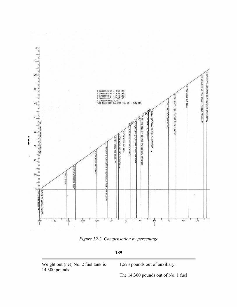
Figure 19-2. Compensation by percentage
189
Weight out (net) No. 2 fuel tank is
14,300 pounds
1,573 pounds out of auxiliary.
The 14,300 pounds out of No. 1 fuel

The forward torpedo rack intersection
with the forward trim tank line shows
that 83.5 percent of the 9,531 pounds
should come out of the trim tank and
the remainder, 16.5 percent, out of the
auxiliary.
7,958 pounds out of trim tank.
tank reads 60.5 percent or 8,650 in the
trim tank, the remaining 39.5 percent of
5,650 in the auxiliary tank.
The 14,300 pounds out of No. 2 fuel
tank reads 48.5 percent or 6,935 pounds
in the trim tank, the remaining 51.5
percent or 7,365 pounds in the auxiliary.
SUMMARY
TANK
OR
SPACE
PERCENT WEIGHT
CHANGE
FORWARD
TRIM AUXILIARY
AFTER
TRIM
F.T. AUX. A.T. Lighter Heavier In Out In Out In Out
Fwd. Racks 83 1/2 16 1/2 9,531 7,958 1,573
No. 1 F.O. 60 1/2 39 1/2 14,300 8,600 5,650
No. 2 F.O. 48 1/2 51 1/2 14,300 6,935 7,365
28,600 9,531 15,585 7,958 13,015
9,531 7,958 1,573
19,069 7,627 11,422
11,442
19,069
Pumping 7,627 pounds into the
forward trim from the sea and flooding
11,442 pounds into the auxiliary, trims
the ship fore and aft and over-all.
Pumping and flooding to the nearest
50 pounds, as is the practice, the
figures would be 11,500 pounds into
the auxiliary and 7,600 pounds into the
forward trim. The ship is 27 pounds
lighter forward and 31 pounds heavy
over-all.
If the location of the weight change is
in the after part of the ship,
compensation is effected by using the
after trim tank and the auxiliary tank.
The computations necessary for any
problem in compensation may be
quickly and easily made by the use of
either of the curves. It is of the utmost
importance, however, that extreme care
be used to include all the weight
changes and to get them in the proper
columns. Small mistakes in the case of
some tanks may make a large error in
the final trim. For example, a 100-pound
mistake in the weight change in the
forward trim tank has the same effect on
the fore-and-aft trim as a 1,040-pound
change in the ammunition and
refrigeration space.
190
20
PATROL ROUTINE
A. INTRODUCTION
20A1. Foreword. The following patrol
instructions are a compilation of
instructions used by various
submarines. Naturally, there
may be some minor differences between
these instructions and those used by a
particularsubmarine.
B. DUTIES OF WATCH STANDERS
20B1. Officer of the deck. On the
surface, the officer of the deck stands
his watch in the forward bridge
structure. Although he is expected to
remain intensely alert and observant, he
is not a lookout and must not become
engrossed in a detail of his watch or a
lookout sector to the exclusion of his
comprehensive duties as supervisor of
the watch. His responsibility when the
ship is submerged is no less than when
on the surface. and a similar degree of
alertness is required in carrying out the
routine and direction of the watch. The
duties of the officer of the deck as
outlined in Navy Regulations, are
supplemented as follows:
Keep the number of persons on the
bridge to a minimum, requiring
permission to come on the bridge in
each case.
Allow only one relief of any watch on
the bridge at a time, with the exception
that besides one lookout relieving, the
quarter master or junior officer of the
deck may relieve.
Insure yourself that the lookout's vision
has become dark-adapted before
allowing him to relieve the watch. A
Keep them as dry as possible and out of
high wind. A comfortable lookout is
much more efficient than an
uncomfortable one.
The following rules apply generally, but
in no way restrict the officer of the deck
from acting as his judgment dictates:
Dive for all aircraft contacts, except as
specifically directed by previous
instructions of the commanding officer.
Turn toward a periscope forward of the
beam and go to full speed. Turn away
from a periscope abaft the beam and go
to full speed.
Turn away from all fishing vessels or
small craft unless ordered by the
commanding officer to attack.
Turn away from unidentifiable objects.
Turn toward a target, but dive in
sufficient time to insure that your ship is
not sighted prior to firing torpedoes.
Present the smallest target possible by
turning toward or away from any type of
contact as the situation dictates.

reasonable test is the lookout's ability at
a distance of about 5 feet to note how
many fingers you have extended.
Keep the lookouts alert and insure that
they are properly covering their sectors.
Insist on standard phraseology in all
reports, with prompt acknowledgments.
Maintain the passageway to the hatch
clear at all times.
Insure that the quartermaster orders
rainclothes for the watch in sufficient
time to permit one person at a time to
don them prior to arrival of a squall.
Place the lookouts where they will be
of most advantage.
In friendly waters, or when contact with
own forces is probable, have daily
recognition signals written in chalk on
wind screen.
Know and insure that all bridge
personnel on watch know the current
signals in effect, and that recognition
gear is in complete readiness as follows:
1. Searchlight tested if rigged.
2. Blinker tube readily accessible.
3. Flares and rockets changed at proper
times.
Carry out the following details or routine:
Approximately 15 minutes before diving
secure the 20-mm guns and ammunition.
Carry out the diving procedure.
After daylight and torpedo routining,
191
the depth at which to run during and
between looks will depend on the state
of the sea and the proximity of enemy
air bases, as directed by the
commanding officer.
When landmarks are available, keep the
ship's position cut in, using periscope
exposures of short duration only.
In making periscope observations, first
sweep the horizon and sky in low
power for aircraft or close surface craft.
Follow this, if all clear, by a slow
deliberate search in high power, not
exposing the periscope for more than
15 seconds. Develop the habit of
obtaining a complete picture of the
weather during your observation. Have
the quartermaster note the keel depth
Obtain the commanding officer's
permission prior to the following:
1. Permitting anyone on deck.
2. Putting any piece of machinery or
armament out of commission.
3. Pulling a torpedo from any tube.
4. Anything that may reduce the fighting
ability of the ship or her ability to dive.
For every sighting while on the surface
that might develop into an attack, sound
the general alarm and let the rest of the
ship know something is happening.
Whenever the need arises to make ready
torpedoes, order " Make ready tubes
forward (or aft)."
Keep the junior officer of the deck

during the observation and also tell you
when 15 seconds of periscope exposure
has occurred.
When the target is sighted, sound the
general alarm, or pass the word over
the telephone if the target is likely to
hear the alarm, and commence the
approach immediately. Minutes or
seconds may be just as valuable then as
later in the attack, and certainly are if
the target is presenting a large angle on
the bow.
Habitually require a smart trim from
your diving officer for the depth at
which you are running.
Notify the commanding officer when
darkness is almost ready to set in and
obtain the time of surfacing from him.
Commence the surfacing procedure.
Ten minutes prior to surfacing, the
commanding officer comes to the
conning tower and relieves the watch.
The junior officer of the deck of the
previous watch relieves the diving
officer a half hour prior to surfacing.
Normally, just prior to surfacing, the
ship is brought to 50 feet for SD sweep,
then to 40 feet for SJ sweep (sound
sweeping all the time).
If "All clear on radar" is indicated,
pass. the work over the loudspeaker, "
Stand by to surface ......... engine
combination." The commanding officer
will then direct the surface alarm be
sounded.
Carry out surfacing procedure on the
surface, alarm.
informed of changes of speed, course, or
any other pertinent information so that he
will be able to assume the deck at any
time.
20B2. Junior officer of the deck. The
junior officer of the deck stands his
watch as directed by the commanding
officer. He may act in any one of three
capacities as follows:
As junior officer of the deck, stationed
forward or aft the cigarette deck. (If aft,
quartermaster should go forward.)
As junior officer of the deck, stationed in
the conning tower.
The junior officer of the deck watch
normally is stood only while on the
surface. Until all officers are fully
qualified as diving officer, the junior
officer of the deck normally acts as
diving officer submerged. However, if
qualified by the commanding officer, he
may interchange with the OOD for
periscope watches if practicable.
Duties of the junior officer of the deck
are as follows:
Supervise the lookouts to insure that they
are covering their sectors properly.
Observe to insure that any enemy that
might possibly get by the lookouts does
not approach, unobserved, to close range.
(If forward, observe from broad on
opposite bow to stern.)
Note the condition of the 20-mm guns
and be prepared to man or direct the fire
as directed by the OOD.
192

Report immediately to the officer of the
deck own engine smoke, sparks, or any
unusual condition.
Proceed to diving station or below on
orders of the officer of the deck or on "
Clear the bridge." Carry out the diving
procedure. Conduct the periscope
watch as directed. Man the TDC and
otherwise assist the OOD in conducting
initial stages of any approach as
directed.
The junior officer of the deck should be
fully aware of the condition of the boat
and prepared to assume the capacity of
the officer of the deck at any time.
20B3. Conning tower talker watch. The conning tower talker watch is
normally stood at all times when at sea.
Conning tower talker watches are stood
as indicated on the Watch, Quarter, and
Station bill.
The duties of this watch may be
outlined as follows:
Instruct new steersmen in their duties.
Make all necessary entries in the
Quartermaster Notebook.
Act as voice link between sound, radar,
control, maneuvering, and bridge
watches.
Supervise zig plan if in use.
Take and record TBT and heading
bearings on bridge buzzer marks.
Act as telephone watch.
Keep conning tower clear of loose gear.
The duties of the steersman are as
follows:
Maintain the course.
Operate the maneuvering room
annunciators as ordered by the bridge.
Know the duties of the conning tower
watch.
Assist the conning tower watch as
necessary and be able to take over at any
time.
Know exactly where all conning tower
alarms are and operate them only when
ordered to do so by the bridge.
20B5. Quartermaster of the watch. The
quartermaster of the watch normally is
stationed on the bridge, aft when
cruising, and may exchange with the
OOD if ordered. He is an additional all-
around lookout and does not restrict his
search to any one sector unless so
ordered by the officer of the deck.
The quartermaster is responsible under
the direction of the OOD for the
following routine duties:
Break out binoculars, dark glasses,
proper flares, and blinker tube prior to
surfacing; also issue lens paper to
lookouts.
Obtain warmer clothing or rainclothing
for lookouts.
Change flares at the proper time.
Check TBT's upon surfacing each night.
Wipe the periscope windows on
surfacing and 15 minutes before routine

Under supervision of the chief petty
officer of the watch, permit but one
relief for any watch to proceed to the
bridge.
At night, check and carry out the night
orders.
Upon surfacing, check TBT's with the
quartermaster as directed.
Assist the quartermaster in maintaining
deck log columns.
Maintain quiet in the conning tower
and keep an alert watch. Report to the
OOD when the conning tower watch is
properly relieved.
Know exactly where all the conning
tower alarms are and operate them only
when ordered to do so by the bridge.
20B4. The steersman. The steersman
is normally stationed in the conning
tower, unless otherwise ordered by the
officer of the deck.
dives.
Operate the periscope, keep the periscope
officer informed of depth, and read and
record bearings when submerged.
Keep the conning tower clean, and all
gear properly stowed when submerged.
Check columns of deck log after being
relieved to make sure that the proper
entries have been made. Do this in the
control room.
Once every hour on surface, check the
lookouts' glasses for cleanliness and
proper setting.
20B6. Chief petty officer of the watch. The CPO of the watch remains in the
control room. He is charged with running
the below deck routine, supervising the
control room watch when on the surface,
and with carrying out the details of the
Watch Bill. He initiates the diving
procedure on the diving alarm, until
relieved of the dive by the
193
diving officer. In carrying out his
duties, he must pay particular attention
to the following:
Call the oncoming watch in sufficient
time for them to relieve 15 minutes
before the hour, in accordance with
naval custom.
At night, insure that each oncoming
lookout is fitted with and wears dark
adaptation goggles continuously for at
least 20 minutes before being allowed
to proceed to the conning tower.
Insure that only one relief proceeds to
2. Pump all the bilges to the sea.
3. Blow all the sanitary tanks.
4. Collect all trash and garbage and when
properly sacked, report to the bridge,
"All trash and garbage assembled," and
dump it when directed.
Carry out evening compensation as
directed by the diving officer.
When orders to the steersman for
changes of course or speed come from
the bridge over the system, observe the
motor order telegraph repeater or rudder
angle indicator in the control room to
check that the order is being carried out

the conning tower at a time.
Promptly acknowledge any orders or
word passed from the bridge or conning
tower.
Periodically check the compensation by
liquidometer gages.
Insure that the proper watch is
maintained on the control room (SD)
radar when ordered manned, and that
any contact, however doubtful, is
reported instantly to the, OOD.
Maintain quiet and allow no loitering in
the control room.
Half an hour prior to surfacing, rig the
hatch skirt. Turn out the white lights;
turn on the red as designated for the
control room.
Execute the 2200 lights out in the
crew's Mess.
At the end of each watch, and
approximately 1 hour before diving,
pump the bilges and blow the sanitary
tanks to the sea.
Keep the manometer needles matched
on surface.
Keep submerged identification signal
available as directed by OOD.
Maintain the air banks at proper
pressure.
See that all the topside reliefs are
properly clothed.
Keep the control room clear of all loose
gear.
properly.
Keep the compass check book, making
entries as required by the navigator.
Instructions will be posted in the front of
the book. While submerged, whenever
word is passed from the conning tower,
"Man battle stations," dispatch one man
forward and one man aft with the order,
"Pass word quietly, wake all hands.
Battle stations submerged."
20B7. Lookouts. Normally there are
three lookouts assigned overlapping
sectors as follows:
Starboard lookout 350 degrees - 130
degrees (relative).
After lookout 120 degrees - 240 degress
(relative).
Port lookout 230 degrees - 010 degrees
(relative). In the event that four lookouts
are used, sectors are assigned as follows:
Starboard forward lookout 350 degrees -
100 degrees (relative).
Starboard after lookout 080 degrees - 190
degrees (relative)
Port after lookout 170 degrees - 280
degrees (relative).
Port forward lookout 010 degrees - 260
degrees (relative).
During daylight, each lookout searches
his sector in the following sequence
using a sun filter only when searching
into the sun:
a. Search the water to the horizon for
one-half of his assigned sector.

About 1 hour before surfacing when
directed by the OOD, pump down the
pressure in the boat to one-tenth.
After surfacing, carry out the evening
routine which consists of the following:
1. After the blowers are secured, start.
air change.
b. Lower the binoculars for
approximately 10 seconds to survey
entire sector, water, and sky, with naked
eye. Continue search of water to horizon
over the remainder of the sector. Search
the horizon and lower sky for one-half of
the assigned sector. Lower binoculars for
approximately 10 seconds to
194
survey the entire sector, water and sky
with the naked eye. Continue search of
the horizon and lower sky over the
remainder of the sector. Repeat 10-
second sweep of the entire sector with
naked eye. Search the upper sky, above
the belt observed when searching the
horizon and lower sky, for one-half of
assigned sector. Lower binoculars for
approximately 10 seconds to survey the
entire sector, water and sky, with naked
eye. Continue search of upper sky for
remainder of sector. Repeat 10-second
sweep of entire sector with naked eye.
Recommence, starting with (a) above.
During darkness, the search will be as
follows:
a. Moonlight nights when enemy air
search is possible: After each complete
sweep of sector, search sky sector with
naked eye.
b. Dark nights: Eliminate sky search.
This method of search has the
following advantages:
It provides a systematic coverage of the
entire area.
It gives maximum insurance against
any plane, which was outside the field
acknowledged and keep on reporting
until you get an acknowledgment.
Do not take eyes or binoculars off the
object you have sighted.
Report everything.
Upon assuming your post after surfacing,
make a complete search of your sector.
Report in a loud clear voice, ".........
sector all clear, sir."
At night, don't attempt night duties until
dark-adapted; avoid short cuts. Practice
use of the corners of the eyes,
remembering that objects are better seen
in dim light if not located in the center of
vision. Move the eyes frequently,
remembering that night vision is most
sensitive immediately after the line of
sight has been shifted. When relieving,
make certain that no other bridge watch
is being. relieved, then request,
"Permission to come on the bridge to
relieve lookout." Relieve with a
minimum of noise and confusion. Get
dressed below for the existing weather
conditions.
20B8. Sound watch. a. General. The
sound watch normally is stood whenever
speed conditions permit. The operator
must, without seeking confirmation or

of the binoculars, closing unobserved to
close range.
Provides best assurance that a periscope
lowered during the binocular search,
will be sighted if dangerously close
during the naked eye sweeps.
General instructions to lookouts:
Save your eyes. All lookouts should
rest their eyes before coming on watch.
They should try to take care of all calls
of nature before going on watch.
If a lookout does not feel physically up
to standing an all-out lookout watch, he
should report this to the OOD.
Make all reports of sightings
immediately. It is better to be wrong
100 tunes than miss one ship.
Use relative bearings in all reports.
Then, followed by your best estimate of
the range, add more information as it
becomes available, stating identity of
ship and so forth.
Call out your reports so that all can
hear. Make certain your report is
help from anyone, report immediately to
the officer of the deck any echo ranging,
propellers, or unusual sounds.
b. Instructions for standing sound
watches. The safety of the ship and its
personnel is directly dependent upon the
manner in which this watch is stood. This
responsibility is greatly increased at night
and a resultant increase in attentiveness is
imperative.
This watch must be stood in regulation
manner. Submerged, each man upon
being. relieved reports to the officer of
the deck, "Sound watch relieved by
..............., Sound conditions are (good,
fair, poor)." On Surface, report to the
conning tower talker that you have been
properly relieved.
Soundheads are to be used in accordance
with communication officer orders
posted at the sound gear.
If for any reason, you have difficulty
interpreting what you hear, or the
equipment
195
does not appear to be operating
correctly, inform the officer of the deck
at once, and call for one of the battle
station soundmen at the same time
without any further orders.
c. Additional information regarding
night sound, watches. Soundheads
should not be left lowered above 10
knots.
When two soundmen are on watch at
Each soundhead should be rotated 360
degrees on alternate sweeps.
If screws are heard, they are to be
reported immediately, stating " Screws at
......... relative, (high or low) speed."
Then obtain the closest true bearing and
report, " True bearing ........." Thereafter,
report any change in speed of screws, and
if you can no longer hear them. Changes
of bearing when own ship is on a steady
course are very important. Keep the

the same time, both soundheads are
lowered. The starboard (JK) operator
covers the sector from zero to 180, and
the port (CQ) operator covers the sector
from 180 to 360.
information coming.
C. DIVING AND SURFACING PROCEDURES
20C1. Diving procedure.
A. Officer of the deck.
1. Pass the word, " Clear the
bridge."
2. Check all hands below.
3. Sound two blasts on the bridge
diving alarm as the last lookout passes
the OOD.
4. When below, check report
Pressure in the boat and order the depth
desired.
5. Commence attack, evasive tactics,
or rig for depth charge as conditions
warrant.
B. Quartermaster.
1. Be last down hatch and shut
hatch.
C. Junior officer of the deck.
1. Be among the first down the hatch
if on the bridge.
2. Proceed immediately to diving
station.
3. Assume control of dive, carrying
out procedure listed under control
room.
D. Lookouts.
1. Clear the bridge on the double
man diving stations in accordance with
the Watch. Quarter, and Station Bill.
E. Conning tower talker watch.
1. Sound the general alarm if
ordered by the OOD.
2. Ring up full speed on the annunciators.
G. Maneuvering room.
1. Answer bells as ordered.
2. Shut the maneuvering room
induction hull valve.
H. Engine room. Procedure in the engine
room is carried out in this order
1. Stop the engines.
2. Shut the outboard exhaust valves.
3. Shut the engine and supply
ventilation induction hull valves.
4. Shut the bulkhead flappers.
5. Shut the inboard exhaust valves.
6. If everything is in order in the
engine rooms-oilers to control room-for
submerged stations.
I. Control room.
1. Open the vents.
2. Rig out the bow planes and put
them on 22-degree dive.
3. When all outboard exhaust valves
are shut or when passing 23 feet shut the
engine air induction and the ship's supply
outboard valve.
4. Bleed air in the vessel and secure
air on orders of the diving officer only in
case the torpedo rooms do not bleed in
air.
5. Note and report pressure in boat.
6. Put the stern planes on dive to take
the ship to the ordered depth with a 4- to
6-degree angle.

2. Lower the periscope if it is up.
F. Helmsman.
1. Put the rudder on as ordered;
otherwise amidship.
196
7. Shut the bow buoyancy at 30 feet
and open the safety for 5 seconds; then
shut it. Shut all vents at 50 feet.
8. Blow the negative to 1,500
pounds in two steps.
9. Reduce the speed and adjust the
trim as necessary.
10. Shut the negative flood and vent
tank inboard.
11. Make certain that the periscopes
are cut in.
12. When convenient, open all
bulkhead flappers and resume normal
hull ventilation.
J. Crew's mess.
1. Report the engine air induction
and hull ventilation valves shut by hand
signal to control room.
2. Lock the above valves shut as
soon as possible and report to control.
K. All stations.
1. Shut the bulkhead flappers.
L. Forward torpedo room and after
torpedo room.
1. Bleed air into the vessel and
secure on word from the control room.
M. Radio room.
1. Disconnect the antenna lead and
shut the trunk flapper.
The conning officer retains speed
control at all times, However, this will
not interfere with or necessitate any
hesitation by the diving officer to
7. On surfacing, be prepared for
immediate diving should circumstances
warrant such action.
8. Upon proceeding to the bridge, the
OOD takes the starboard side and
searches, the JOOD takes the port side,
and the QM the after half of ship. When
all three have reported, "All clear," call
to conning tower, "Routine."
9. When the word, "Routine" is
passed, the officer in the conning tower
sees that the following procedure is
carried out:
a) Main induction opened.
b) Lookouts to the bridge.
c) Engines are automatically started
on opening of induction.
d) Turbo blow for 6 minutes.
c) Gunner's mate to bridge to rig 20
mm.
f) Rig in soundhead if going two-
thirds speed.
g) After steps a) to e) have been
carried out, announce to control, "Carry
out all routine below."
b. Helmsman.
1. When the surfacing alarm is
sounded, ring up two-thirds speed unless
otherwise ordered.
c. Quartermaster.
1. Stand by the hatch.
2. Sound the surfacing alarm on
orders of the C.O. only.
3. Open the hatch on orders from the
C.O.

request speed changes to facilitate
depth control.
20C2. Surfacing procedure.
a. Duties of the officer of the deck.
1. Prior to surfacing, carry out
surfacing routines as outlined in the
front of the QM notebook.
2. Have the sound watch make an
exacting search.
3. Keep the periscope watch as
directed.
4. Give control any changes in
ordinary surface procedure.
5. Pass the word, "Stand by to
surface ......... engine combination."
6. Follow the commanding officer
and the quartermaster to the bridge.
(The JOOD follows the OOD to the
bridge.)
d. Assistant navigator (quartermaster).
1. Keep the C.O. informed of keel
depth and pressure in boat.
e. Control.
1. Start the hydraulic plant at 50 feet.
2. Rig in the bow planes when the
word is passed to stand by to surface
......... engine combination.
3. Blow the bow buoyancy and main
ballast, except the safety, on the third
blast of the surface alarm. Surface with
3-4 degree rise angle and secure the air
when at 30 feet.
4. When the conning tower hatch
shows a red light, and the hatch is heard
197
to open, vent and flood the negative.
Vent and shut the safety.
5. Open the main induction on
orders from the conning tower.
6. Put the low-pressure blowers on
tank as directed.
7. CPO of the watch: Carry out
routine as directed. "Carry out all
routine below" means:
a) Have the battery charge started.
b) Blow all the sanitary tanks.
c) Pump all the bilges in succession
from aft to forward.
d) Assemble trash and garbage in
control room.
c) Speed up the exhaust and supply
blowers.
f) Start the air change after stopping
the turbo blow.
g) Swab down and clean all
compartments.
h) Report to the bridge that "All
routine is being carried out below."
20C3. Check-off list prior to surfacing.
a. Procedure 30 minutes prior to
surfacing
1. Pump down the pressure in the boat
to 0.1 inch upon orders of the C.O.
2. Start the hydrogen detectors and
line up the battery ventilation for charge.
Take individual cell reading.
3. Call the lookouts and have them
dress appropriately for the weather.
4. Quartermaster: Clean all binoculars
and get dressed to go to the bridge.
5. Bring .45-caliber pistol and
submachine gun to the conning tower
with two drums of ammunition.
6. Get readings on all sanitary tanks,
bilges, and fresh water tanks and record
them for final trim estimate.
7. Rig the curtain in the control room.
Darken the control room and conning
tower.

8. Be prepared to dive again
immediately.
f. Crew's mess.
1. Unlock and put the hull
ventilation supply and engine air
induction valves on power, on "Stand
by to surface=." Report to control when
this is accomplished.
g. Maneuvering room.
1. Answer bells as ordered. After the
surface alarm is sounded, shift to
surface rpm.
2. Ring up "Start" on the engines
desired.
3. Shift to engines for propulsion
when the engine room is ready and start
the battery charge as soon as possible.
4. Report to the conning tower as
soon as the battery charge is started.
h. Engine room.
1. When "Start" is received from the
maneuvering room and when the
outboard engine air induction valve is
opened, start the engines as ordered,
Carry out the normal routine.
b. Procedure 15 minutes prior to
surfacing.
1. Notify the maneuvering room and
engine rooms to stand by engine
combination in accordance with night
orders.
2. Check to ascertain that all lookouts
are in the control room dressed to go on
watch with dark glasses.
3. Navigator: Relieve the OOD to get
dressed for surfacing.
4. Diving officer on proceeding to
watch: Relieve the diving officer to get
dressed for surfacing and the JOOD
watch.
5. Trim manifold man: Relieve the
bow planesman to get dressed for
surfacing.
6. Start up the SJ radar and have the
radio technician man the SJ radar in the
conning tower.
c. Procedure upon surfacing.
1. Immediately upon surfacing, stern
planesman and trim manifold man go to
the engine rooms.
198
D. APPROACH OFFICER
20D1. Approach officer's check-off
list.
a. Make torpedoes ready early, Set the
depth and speed on the torpedo.
b. Give the identification officer all
necessary information early.
c. Slow sufficiently for safe periscope
observation.
observations for air patrol and other
surface patrol craft.
e. Make observations frequently.
f. As range decreases, run at deeper
depth.
g. Keep the ship informed of progress of
approach as consistent with
circumstances.

d. Make sufficient all-around h. Rig the ship for depth charge attack.
E. TORPEDO ROOMS
20E1. Instructions for torpedo
rooms.
a. At least one qualified torpedoman
must he on watch in each torpedo room
at all times. The phones should be
manned continuously.
b. Gyro spindles should be engaged at
all times, and in the absence of other
instructions, torpedoes set on 0 degrees
forward and 180 degrees aft.
c. Unless otherwise instructed by
proper authority, the condition of the
gyro regulators should be:
1. Clutch in automatic and switch on.
d. All torpedoes are to be set for high
speed and 10-foot depth until ordered
changed from the conning tower. Depth
setting spindles should be left
disengaged.
e. When the order, "Make ready the tubes
forward (aft)" is received, all tubes in the
nest must be made ready as rapidly as
possible and, as far as possible, in
numerical order.
f. Unless word is received to the
contrary, the firing order is always in
numerical order.
g. Tubes should always be flooded from
WRT. In case of an emergency, when
submerged, that prevents tubes from
being flooded from WRT, request
permission from the diving officer to
flood the tubes from the sea. If on the
surface, notify the diving officer, and
flood from the sea.
h. The senior torpedoman in each room is
responsible for these orders being
properly carried out.
F. STANDARD PHRASEOLOGY
20F1. Examples of standard
phraseology. The following is the standard
phraseology to be used on phones and
when passing the word:
a. Torpedoes.
1. Make ready the bow (stern) tubes.
2. Set torpedo depth 10 feet.
3. What is the torpedo run?
4. What is the gyro angle?
5. Do the bow (stern) tubes bear?
6. Check fire (or cease fire).
7. When gyro angle is zero,
commence firing.
8. Use one (six) torpedoes.
11. Stand by one, and so on. Fire one,
and so on.
12. What is the torpedo track angle?
b. Own ship-fire Control.
1. What is the pit log speed?
2. Pit log speed is .........
3. What is our head(ing) (course)?
4. Our head(ing) (course) is .........
5. Left (right) 5 degree rudder.
6. Rudder is 5 degree (10 degree)
(full), right (left).
7. Depth 60 (etc.) feet.
8. Emergency, 200 (150) feet.
9. Take her down.
10. Rig ship for depth charge attack.

9. Use angle, speed, bearing
(periscope) spread.
10, Set gyro regulators in hand
(automatic).
11. Stand by to dive (clear the bridge).
199
12. What is the log distance?
c. Target.
1. (Generated) angle on the bow is
......... starboard (port).
2. Estimated (generated) (radar)
(sound) range, five oh double oh.
3. Estimated target speed .........
knots (low 2-10) (moderate 10-15)
(high 15-25)
4. Target is maru (destroyer) (man-
o-war) etc.
5. Target (relative) (Sound) (Radar)
(True) (generated) bearing is .........
6. Estimated (generated) target
course is .........
7. Stand by for a set-up.
8. Target estimated length is .........
9. Target track angle is .........
10. Set-up is good. (T.D.C. set-up.)
d. Own ship: administration.
1. Put low-pressure blowers on all
main ballast tanks for ......... minutes.
2. What time is it?
3. Rig ship for depth charge attack.
4. Forward room rigged for depth
charge attack.
5. Open all bulkhead flappers,
resume normal hull ventilation.
6. Get ready on the engines.
7. Shift to the battery.
8. Man the sound gear. (Station the
sound watch.)
9. Man the radio room (conning
tower) radar.
10. House the underwater log.
11. Rig out the underwater log.
12. Lower and lock the port
(starboard) soundhead.
13. Raise and lock the port (starboard)
soundhead.
14. Open the main induction, start the
blowers.
15. Lookouts to the bridge.
e. Orders to the men on the lines.
Slack off: Pay out the line, allowing it
to form an easy bight.
Take a strain: Put the line under
tension.
Take in the slack: Heave in on the
line, but do not take a strain.
Ease it, Ease away, or Ease off: Pay
out enough to remove most of the strain.
Check Number .........: Hold the line,
but render it enough when necessary so
that it will not part.
Hold Number .........: Take sufficient
turns that the line will not give.
Double up and secure: Run any
additional lines and double all of them as
necessary.
Stand by your lines: Man the lines,
ready to cast off.
Cast off Number .........: Let go
Number ......... line.
200
21

SUBMARINE TRAINING DEVICES
A. GENERAL
21A1. Introductory. The modern feet-
type submarine is an exceedingly
complex mechanism. On the surface, in
normal operation, it presents all the
problems of ship handling and
navigation common to surface vessels.
Its problems do not end there, however,
for when it submerges it becomes, in
effect, an entirely different vessel with
new characteristics and new problems.
Submerged, the control becomes more
complicated; the ship must be
navigated in a three-dimensional
medium and many conditions affecting
its operation are much more critical
than when it is on the surface. Added to
these complexities are the more limited
facilities for observation and the
necessity of relying, to a great extent,
on dead reckoning.
As the submarine is an offensive
weapon, its chief value against the
enemy is its ability to approach
undetected and to maneuver to a firing
position despite the target's efforts to
avoid contact. The approach and attack
phase of submarine warfare is a science
in itself, requiring a practiced eye, an
analytical mind, and the ability to make
swift and accurate decisions. Though
the possession of these attributes is a
paramount requirement
for submarine officers, to be of value in
submarine attack they must be
supplemented with long experience and
thorough training.
In the early days of the submarine this
experience and training were acquired
through actual service under a competent
commanding officer. With the growth of
the fleet and the phenomenal
development of the submarine and its
equipment, it became evident that
qualified personnel must be secured in
ever increasing numbers and trained
more rapidly. To this end, numerous
training devices, duplicating the more
important features of a submarine, have
been developed and may be used to
simulate actual situations encountered or
patrols.
Three departments of the submarine have
been the object of particular attention, the
conning tower, the control room, and the
torpedo room, resulting in the production
of three devices known as the attack
teacher, the diving trainer and the
torpedo tube trainer. These devices are
used to train fire-control parties, diving
officers, and control room personnel, and
to instruct in the care and manipulation
of torpedoes and torpedo tubes and in the
firing of torpedoes.
B. THE ATTACK TEACHER
21B1. Description . The attack teacher
is a device by which typical approach
and attack problems may be duplicated
in all their phases. The fire-control
party in training is assembled in a
the conduct of an actual operation against
an enemy.
Early attack teachers bore little
resemblance to the devices of the present

mock-up conning tower. Miniature
models of enemy vessels are
maneuvered in the field of a specially
designed periscope and the fire-control
party simulates
day. Like the submarines, they have
developed rapidly, and they now afford a
reliable presentation of battle problems
and facilities for their solutions.
C. THE DIVING TRAINER
21C1. Description. The diving trainer
(Figure 21-1) consists of a duplicate of
the port side of the control room with
all the apparatus and equipment usually
installed in that section of the
submarine. The control zoom section is
mounted so that it may be tilted to
assume all the normal up-and-down
angles encountered in the actual
operation of a submarine. The
instruments and controls are mounted in
their relative locations and all function
just as when actually installed on a
submarine.
201
Figure 21-1. The diving trainer

202
Figure 21-2. The torpedo tube trainer
203
The device is operated from a control
stand in front of the room. This stand
is the station of the instructor and
affords him a full view of all the
gages, instruments, and members of
the control room personnel. The
controls not normally installed on the
officer, then issues the necessary orders
to attain the desired condition of the
submarine. Every action necessary to
diving, trimming, and surfacing the ship
is carried out to the most exact detail
and the response of the tilting section of
the control room and the registry of the

port side of the control room are
mounted in their relative positions at
the side of the lecture room.
Electric and hydraulic controls enable
the instructor to create conditions
which are normally encountered and
registered on the instruments. The
student, acting as diving
gages indicate to the student the same
result as would be obtained with an
actual submarine.
The use of this trainer has shortened the
training period otherwise necessary and
permits the training of an increased
number of students.
D. THE TORPEDO TUBE TRAINER
21D1. Description. A recent
innovation in training devices is an
installation of a standard torpedo tube
with all controls, interlocks, and
mechanisms, and from which a
standard torpedo may be fired and the
procedure observed. (See Figure 21-2.)
The tube itself is an exact duplicate of
those installed in the fleet-type
submarines. The tube is mounted on
the end of a water tight tank in which
varying pressures, corresponding to
assumed depths, can be attained. The
torpedo tube muzzle extends into the
tank and is fitted with the standard
muzzle door. Guides along the bottom
of this tank, and above the course of
the fired torpedo, are installed to
prevent any erratic course once the
torpedo leaves the tube.
Heavy glass windows in the side of the
tank permit observations to be made of
the torpedo's exit from the tube and the
amount of bubble checked.
The torpedo is loaded into the tube and
is fired in a normal manner and at
normal speeds. At the rear end of the
tank the torpedo enters a restricted
passage. The water expelled from this
passage exhausts through gradually
reduced orifices and the torpedo is
brought to a gentle stop. It is then
pushed back through the tank and tube
to the loading rack where it may be used
again.
A gyro angle indicator regulator is
mounted near the tube and any normal
operation connected with torpedo fire
may be duplicated.
204