Embed Size (px)
Citation preview
4634 IEEE TRANSACTIONS ON NUCLEAR SCIENCE, VOL. 60, NO. 6, DECEMBER 2013
Noise Analysis in Pulse-ProcessingDiscrete-Time Filters
Diego Avila, Student Member, IEEE, Enrique Alvarez, Student Member, IEEE, and Angel Abusleme, Member, IEEE
Abstract—Discrete-time filters represent a promising solutionfor pulse-processing in high-energy physics experiments dueto their flexibility, reliability, and their capability to synthesizeweighting functions with virtually any shape. One of the majorconcerns when designing one of these filters is to calculate thefilter parameters that maximize the signal-to-noise ratio. Theclassic way to address this problem is to perform the noise analysisusing a continuous-time domain approach based on the weightingfunction concept. However, when addressing the problem froman inadequate time domain, the analysis is not insightful andthe resulting expressions are complex and difficult to use fordesign purposes. In this work, a mathematical framework for adesign-oriented analysis of discrete-time filters in the discrete-timedomain is presented. This analysis is based on treating the samplednoise as a discrete-time signal, which can be manipulated to obtaina closed-form expression for the front-end noise, suitable for com-puter automatic evaluation and filter optimization procedures.An example of the optimum filter formulation and computationis presented, in addition to several conclusions about optimumdigital filtering.
Index Terms—Charge measurements, low-noise filters, noise,nuclear physics instrumentation, optimum digital filtering.
I. INTRODUCTION
I N PARTICLE physics experiments, where the results fromthe collisions are inferred from the measurement of elec-
tric charge in various sets of detectors [1], [2], noise sets a fun-damental limit for the charge measurement resolution [3]. Insuch experiments, the typical detector front-end circuit com-prises a charge-sensitive amplifier (CSA) and a filter, often re-ferred to as pulse shaper. The former is used to convert theinput charge signal, coming from the detector electrodes, intoa voltage signal, and is responsible for most of the noise presentin the readout circuit signal path [3], [4]. The filter is used to con-vert the voltage signal at the CSA output into a shaped voltagepulse, in order to maximize the signal-to-noise ratio (SNR) atthe measurement time.Different noise analysis methods have been proposed to
guide a proper filter design. The outcome of these methods isthe equivalent noise charge (ENC), a measure of the front-endnoise defined as the charge required at the detector input toproduce an output SNR of 1. A time-domain analysis based onthe weighting function (WF) concept [2], [5] has long been the
Manuscript received February 19, 2013; revised July 26, 2013; acceptedSeptember 17, 2013. Date of publication November 11, 2013; date of currentversion December 11, 2013. This work was supported by the National Com-mission for Scientific and Technological Research (CONICYT) of Chile, undergrant FONDECYT 11110165 and scholarship CONICYT-PCHA/Magı́sterNacional/2013—folio 221320673.D. Avila, E. Alvarez and A. Abusleme are with the Department of Electrical
Engineering, Pontificia Universidad Católica de Chile, Casilla 306, Correo 22,Santiago, Chile. (e-mail: [email protected]; [email protected]; [email protected]).Digital Object Identifier 10.1109/TNS.2013.2283242
preferred analysis, since it allows to find the optimum filter fora wide range of detector configurations [6]–[10].Traditionally, the filter synthesis has been performed using
continuous-time networks. However, since producing arbitraryWFs by means of continuous-time analog circuitry is often im-possible [8], this approach does not always allow to synthesizeoptimum filters. A different approach based on discrete-time fil-ters, implemented by means of digital signal processor (DSP)units [11]–[13] or switched capacitor networks [14]–[16], al-lows to synthesize WFs with virtually any shape, producingnear-optimum filters. Moreover, this promising approach takesadvantage of the aggressive technology scaling and the newtechniques of the VLSI industry, allowing to implement fast,reliable and flexible filters.In this work, a mathematical framework for a design-oriented
analysis of discrete-time filters in the discrete-time domain ispresented. Although discrete-time filters can be analyzed usinga continuous-time method, it is not insightful and the resultingexpressions are complex and difficult to use for design pur-poses. Furthermore, the analysis of discrete-time filters in thediscrete-time domain provides a better insight on how their dis-crete nature affects the front-end noise. The proposed analysiscan produce closed-form expressions for the ENC calculation,which can be used for efficient algorithms for the ENC evalua-tion and filter optimization procedures.In order to validate the proposed framework in this paper, an
example is developed, and the result obtained is analyzed andcompared with the result provided by the continuous-time ap-proach. Also, an example of optimal filter computation is pre-sented to demonstrate the capabilities of the proposed frame-work.
II. DISCRETE-TIME ANALYSIS
Fig. 1 shows a simplified model to compute the output-re-ferred noise contribution of a single noise source in a typicalfront-end detector. It consists of a linear block with a transferfunction that models the effect of the CSA on the noisesource under analysis, and a pulse shaper, which in this case is afinite impulse response (FIR) filter with a discrete-time transferfunction given by
(1)
where are arbitrary coefficients and is the filter length.The noise source is characterized by its two-sided power spec-tral density (PSD) .For this analysis it is not necessary to consider the details of
the physical processes that cause the noise. It will be assumedthat the noise source is an arbitrary white or filtered white noise
0018-9499 © 2013 IEEE

AVILA et al.: NOISE ANALYSIS IN PULSE-PROCESSING DISCRETE-TIME FILTERS 4635
Fig. 1. Model for noise analysis in a typical front-end circuit.
source, which represents any of the fundamental noise sourcespresent at a detector front-end circuit, such as thermal noise,shot noise and flicker noise. This assumption allows to modelthe noise source in the time domain in terms of a sequence ofnoise pulses with core function , arriving Poissonianly attimes with an average rate and random sign [2], [5]. Ageneral procedure to calculate a function that representsthe noise process characterized by can be found in [17].By using the CSA transfer function and , the effect of an
individual noise pulse at the filter input can be determined as
(2)
Both sequences of pulses, at the input and at the output of ,are illustrated in Fig. 1.Assuming a periodic, synchronous front-end, where the stim-
ulus arrival time within each frame is fixed and known, the CSAcan be reset at the beginning of each frame, prior to the corre-sponding stimulus. Thus, the analysis can be carried out consid-ering a non-stationary noise process that starts at . Then thetotal integrated noise at the filter input is a function of time [18].Using (2) and Campbell’s theorem, the following expression forthe total integrated noise at the filter input can be derived:
(3)
Let us define as the time interval between an arbitrarysample and its predecessor, given by ,where is the filter sampling period. Now consider the noisecontribution of the pulses originated within and measured atan arbitrary sample (i.e., ), , as shown in Fig. 2.Using Campbell’s theorem, can be computed as
(4)
As shown in the Appendix, (4) can be expressed in terms of (3)as follows:
(5)
Based on (5), the total integrated noise at the filter input mea-sured at the th sample, , can be written as the sum ofthe individual noise contributions originated at each interval
(6)
Fig. 2. Noise contribution of the pulses generated within and measured at anarbitrary sample (i.e., ), using an arbitrary filtered noise core function
. The independent contribution of each pulse is pointed out with black dots.
Fig. 3. Evolution of the total integrated noise at the filter input, where the noiseof each sample was split according to (6).
The evolution of the total integrated noise at the filter input ac-cording to (6) is illustrated in Fig. 3.Since (6) is composed by noise contributions originated
at different time intervals , the total integrated noise at thefilter input holds partial correlation between samples, and theoutput noise cannot be computed by convolving (6) with .However, since all evaluations of are originated fromthe same pulses (for a fixed ), and thus are fully correlated,(6) can be split into independent discrete-time signals
. Each of these signals can be referredto the filter output as
(7)
4636 IEEE TRANSACTIONS ON NUCLEAR SCIENCE, VOL. 60, NO. 6, DECEMBER 2013
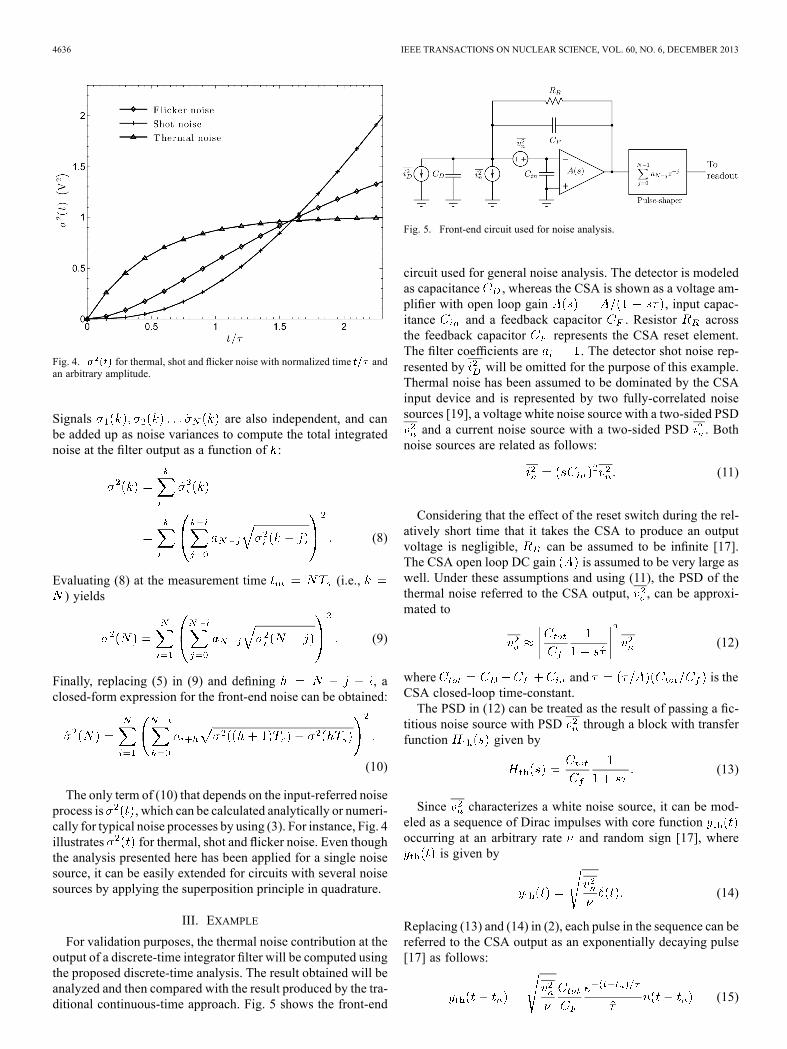
Fig. 4. for thermal, shot and flicker noise with normalized time andan arbitrary amplitude.
Signals are also independent, and canbe added up as noise variances to compute the total integratednoise at the filter output as a function of :
(8)
Evaluating (8) at the measurement time (i.e.,) yields
(9)
Finally, replacing (5) in (9) and defining , aclosed-form expression for the front-end noise can be obtained:
(10)
The only term of (10) that depends on the input-referred noiseprocess is , which can be calculated analytically or numeri-cally for typical noise processes by using (3). For instance, Fig. 4illustrates for thermal, shot and flicker noise. Even thoughthe analysis presented here has been applied for a single noisesource, it can be easily extended for circuits with several noisesources by applying the superposition principle in quadrature.
III. EXAMPLE
For validation purposes, the thermal noise contribution at theoutput of a discrete-time integrator filter will be computed usingthe proposed discrete-time analysis. The result obtained will beanalyzed and then compared with the result produced by the tra-ditional continuous-time approach. Fig. 5 shows the front-end
Fig. 5. Front-end circuit used for noise analysis.
circuit used for general noise analysis. The detector is modeledas capacitance , whereas the CSA is shown as a voltage am-plifier with open loop gain , input capac-itance and a feedback capacitor . Resistor acrossthe feedback capacitor represents the CSA reset element.The filter coefficients are . The detector shot noise rep-resented by will be omitted for the purpose of this example.Thermal noise has been assumed to be dominated by the CSAinput device and is represented by two fully-correlated noisesources [19], a voltage white noise source with a two-sided PSDand a current noise source with a two-sided PSD . Both
noise sources are related as follows:
(11)
Considering that the effect of the reset switch during the rel-atively short time that it takes the CSA to produce an outputvoltage is negligible, can be assumed to be infinite [17].The CSA open loop DC gain is assumed to be very large aswell. Under these assumptions and using (11), the PSD of thethermal noise referred to the CSA output, , can be approxi-mated to
(12)
where and is theCSA closed-loop time-constant.The PSD in (12) can be treated as the result of passing a fic-
titious noise source with PSD through a block with transferfunction given by
(13)
Since characterizes a white noise source, it can be mod-eled as a sequence of Dirac impulses with core functionoccurring at an arbitrary rate and random sign [17], where
is given by
(14)
Replacing (13) and (14) in (2), each pulse in the sequence can bereferred to the CSA output as an exponentially decaying pulse[17] as follows:
(15)

AVILA et al.: NOISE ANALYSIS IN PULSE-PROCESSING DISCRETE-TIME FILTERS 4637
Fig. 6. and as a function of , usingand .
where is the unit step function. Substituting (15) in (3), thefilter input total integrated noise due to the thermal noise, ,can be derived
(16)
Finally, replacing (16) in (10) and defining , thefront-end noise, , can be obtained
(17)
When the time interval between samples is large enough toconsider that consecutive noise samples are uncorrelated (i.e.,
), can be approximated without the use of theproposed analysis as a weighted sum of the uncorrelated sam-ples of the total integrated noise at the CSA output as follows:
(18)
As shown in Fig. 6, (17) behaves as predicted by (18) forsmall values of .Now, the same example will be analyzed using the traditional
continuous-time approach. Using (15), the WF , defined asthe contribution of each pulse occurring at time measured at afixed time at the output of the filter, is given by
(19)
Integrating (19) from the reset time to the signal mea-surement time , the filter total integrated noise at
can be computed as
(20)
Defining and , (20) can be rewritten as
(21)
which can be split into a sum of integrals as follows:
(22)
Finally, defining it can be shown that (22) is equal to(17).
IV. ENC MINIMIZATION
For filter optimization purposes, a typical front-end circuitwith thermal, shot and flicker noise components is considered.The front-end configuration from Fig. 5 will be used. In thiscase, the pulse shaper is a discrete-time FIR filter with indeter-minate coefficients . Shot noise is assumed to be dominatedby the detector noise and is represented by a white noise currentsource with two-sided PSD in parallel with the detector ca-pacitance and given by
(23)
where is the electron charge and the detector leakage cur-rent. Thermal noise and flicker noise are assumed to be domi-nated by the noise of the CSA input device and are representedby two fully-correlated noise sources, a voltage noise sourcewith two-sided PSD given by
(24)
where and are the thermal and flicker coefficients, and acurrent noise source with two-side PSD given by (11). Tradi-tionally, the coefficients and are obtained from the CSAinput device models. However, for design purposes the most ac-curate values shall be used, and these coefficients should be ex-tracted from experiments [20] or precise simulations.Considering the contribution of each noise process separately,
the for the output measured at can be writtenas
(25)
where is the shot noise contribution, is thethermal noise contribution, is the flicker noise contri-
4638 IEEE TRANSACTIONS ON NUCLEAR SCIENCE, VOL. 60, NO. 6, DECEMBER 2013
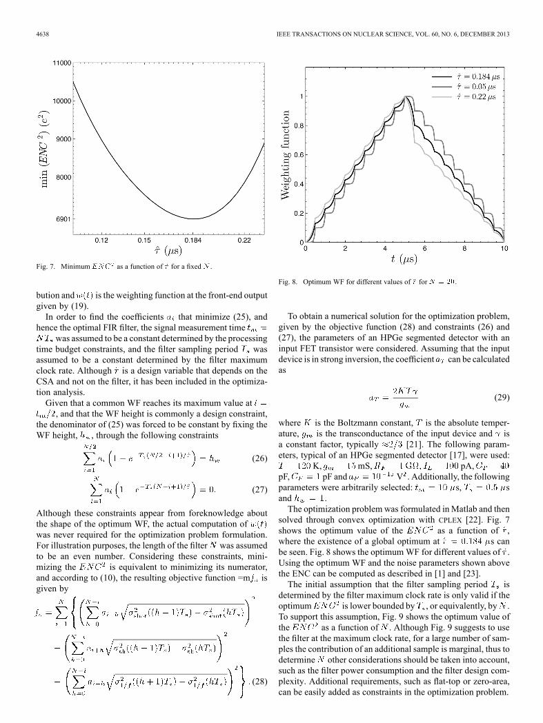
Fig. 7. Minimum as a function of for a fixed .
bution and is the weighting function at the front-end outputgiven by (19).In order to find the coefficients that minimize (25), and
hence the optimal FIR filter, the signal measurement timewas assumed to be a constant determined by the processing
time budget constraints, and the filter sampling period wasassumed to be a constant determined by the filter maximumclock rate. Although is a design variable that depends on theCSA and not on the filter, it has been included in the optimiza-tion analysis.Given that a common WF reaches its maximum value at, and that the WF height is commonly a design constraint,
the denominator of (25) was forced to be constant by fixing theWF height, , through the following constraints
(26)
(27)
Although these constraints appear from foreknowledge aboutthe shape of the optimum WF, the actual computation ofwas never required for the optimization problem formulation.For illustration purposes, the length of the filter was assumedto be an even number. Considering these constraints, mini-mizing the is equivalent to minimizing its numerator,and according to (10), the resulting objective function =m isgiven by
(28)
Fig. 8. Optimum WF for different values of for .
To obtain a numerical solution for the optimization problem,given by the objective function (28) and constraints (26) and(27), the parameters of an HPGe segmented detector with aninput FET transistor were considered. Assuming that the inputdevice is in strong inversion, the coefficient can be calculatedas
(29)
where is the Boltzmann constant, is the absolute temper-ature, is the transconductance of the input device and isa constant factor, typically [21]. The following param-eters, typical of an HPGe segmented detector [17], were used:
K, mS, pA,pF, pF and V . Additionally, the followingparameters were arbitrarily selected: s, sand .The optimization problem was formulated inMatlab and then
solved through convex optimization with CPLEX [22]. Fig. 7shows the optimum value of the as a function of ,where the existence of a global optimum at s canbe seen. Fig. 8 shows the optimumWF for different values of .Using the optimum WF and the noise parameters shown abovethe ENC can be computed as described in [1] and [23].The initial assumption that the filter sampling period is
determined by the filter maximum clock rate is only valid if theoptimum is lower bounded by , or equivalently, by .To support this assumption, Fig. 9 shows the optimum value ofthe as a function of . Although Fig. 9 suggests to usethe filter at the maximum clock rate, for a large number of sam-ples the contribution of an additional sample is marginal, thus todetermine other considerations should be taken into account,such as the filter power consumption and the filter design com-plexity. Additional requirements, such as flat-top or zero-area,can be easily added as constraints in the optimization problem.

AVILA et al.: NOISE ANALYSIS IN PULSE-PROCESSING DISCRETE-TIME FILTERS 4639
Fig. 9. Optimum as a function of for s.
V. CONCLUSION
This work presents a mathematical framework for the anal-ysis of discrete-time filters in the discrete-time domain. Theanalysis is based on decomposing the total integrated noise atthe filter input into a set of discrete-time noise signals, in orderto refer them to the filter output and calculate the ENC. Theproposed analysis only depends on the calculation of the totalintegrated noise at the filter input, which can be analyzed priorto taking into account the filter itself in order to understand andpredict the noise behavior.In order to validate the proposed framework, the computa-
tion of the thermal noise contribution at the output of a dis-crete-time integrator is presented, and the result is compared tothe result produced by the traditional continuous-time approach.Although both methods produce mathematically equivalent re-sults, the former is simpler and more insightful.This work also presents an example of optimal filter computa-
tion, in order to demonstrate the proposed framework capabil-ities and its application to optimization problems with severalnoise sources.
APPENDIX
It can be shown that , given by (4), can be expressed as
(30)
where . This integral can be split into twointegrals as follows:
(31)
Defining , (31) can be written as
(32)
Since is zero for negative arguments, then for. For , and according to (3), (32) can be alternatively
expressed as
(33)
Therefore
(34)
ACKNOWLEDGMENT
The authors would like to thank the colleagues from theFCAL collaboration for discussions and advice.
REFERENCES
[1] E. Gatti and P. Manfredi, “Processing the signals from solid-state de-tectors in elementary-particle physics,” Riv. Nuovo Cim., vol. 9, pp.1–146, 1986.
[2] V. Radeka, “Low-noise techniques in detectors,” Ann. Rev. Nucl. Part.Sci., vol. 38, no. 1, pp. 217–277, 1988.
[3] G. D. Geronimo, P. O’Connor, V. Radeka, and B. Yu, “Front-end elec-tronics for imaging detectors,”Nucl. Instrum. Meth., vol. A471, no. 12,pp. 192–199, 2001.
[4] G. De Geronimo and P. O’Connor, “MOSFET optimization in deepsubmicron technology for charge amplifiers,” IEEE Trans. Nucl. Sci.,vol. 52, no. 6, pp. 3223–3232, Dec. 2005.
[5] F. Goulding, “Pulse-shaping in low-noise nuclear amplifiers: A phys-ical approach to noise analysis,” Nucl. Instrum. Meth., vol. 100, no. 3,pp. 493–504, 1972.
[6] V. Radeka, “Optimum signal-processing for pulse-amplitude spec-trometry in the presence of high-rate effects and noise,” IEEE Trans.Nucl. Sci., vol. NS-15, no. 3, pp. 455–470, 1968.
[7] A. Geraci and E. Gatti, “Optimum filters for charge measurements inthe presence of 1/f current noise,” Nucl. Instrum. Meth., vol. A361, no.2, pp. 277–289, 1995.
[8] E. Gatti, A. Geraci, and G. Ripamonti, “Automatic synthesis of op-timum filters with arbitrary constraints and noises: A new method,”Nucl. Instrum. Meth., vol. A381, no. 1, pp. 117–127, 1996.
[9] A. Pullia, “How to derive the optimum filter in presence of arbitrarynoises, time-domain constraints, and shaped input signals: A newmethod,” Nucl. Instrum. Meth., vol. A397, pp. 414–425, 1997.
[10] A. Pullia and E. Gatti, “Optimal filters with constant-slope crossoverand finite width for pulse-timing measurements,” IEEE Trans. Nucl.Sci., vol. 49, no. 3, pp. 1170–1176, Jun. 2002.
[11] A. Geraci, M. Zambusi, and G. Ripamonti, “A comparative study ofthe energy resolution achievable with digital signal processors in X-rayspectroscopy,” IEEE Trans. Nucl. Sci., vol. 43, no. 2, pp. 731–736, Apr.1996.
[12] M. Sampietro, G. Bertuccio, A. Geraci, and A. Fazzi, “A digital systemfor “optimum” resolution in X-ray spectroscopy,” Rev. Sci. Instrum,vol. 66, no. 2, pp. 975–981, 1995.
[13] V. T. Jordanov, “Real time digital pulse shaper with variable weightingfunction,” Nucl. Instrum. Meth., vol. A505, no. 1, pp. 347–351, 2003.
[14] M. Porro, S. Herrmann, and N. Hornel, “Multi correlated double sam-pling with exponential reset,” in IEEE Nucl. Sci. Symp. Conf. Rec,2007, vol. 26, no. 3, pp. 291–298.
[15] C. Fiorini and W. Buttler, “Multicorrelated double sampling readoutof asynchronous events from multi-element semiconductor detectors,”IEEE Trans. Nucl. Sci., vol. 49, no. 3, pp. 1566–1573, Jun. 2002.

4640 IEEE TRANSACTIONS ON NUCLEAR SCIENCE, VOL. 60, NO. 6, DECEMBER 2013
[16] A. Abusleme, A. Dragone, G. Haller, and B. Wooley, “Beamcal instru-mentation IC: Design, implementation, and test results,” IEEE Trans.Nucl. Sci., vol. 59, no. 3, pp. 589–596, Jun. 2012.
[17] A. Pullia and S. Riboldi, “Time-domain simulation of electronicnoises,” IEEE Trans. Nucl. Sci., vol. 51, no. 4, pp. 1817–1823, Aug.2004.
[18] V. Radeka, “Signal processing for particle detectors,” in Detectors forParticles and Radiation. Part 1: Principles and Methods, ser. Lan-dolt-Börnstein—Group I Elementary Particles, Nuclei and Atoms, C.Fabjan and H. Schopper, Eds. Berlin, Germany: Springer, 2011, vol.21B1, pp. 288–319.
[19] W. Sansen and Z. Chang, “Limits of low noise performance of detectorreadout front ends in CMOS technology,” IEEE Trans. Circuits Syst.,vol. 37, no. 11, pp. 1375–1382, Nov. 1990.
[20] G. Bertuccio and A. Pullia, “A method for the determination of thenoise parameters in preamplifying systems for semiconductor radiationdetectors,” Rev. Sci. Instrum, vol. 64, no. 11, pp. 3294–3298, 1993.
[21] A. Van Der Ziel, “Noise in solid-state devices and lasers,” Proc. IEEE,vol. 58, no. 8, pp. 1178–1206, Aug. 1970.
[22] IBM, ILOG CPLEX Optimizer [Online]. Available: http://www.ilog.com/products/cplex/
[23] A. Pullia, “Impact of non-white noises in pulse amplitude measure-ments: A time-domain approach,” Nucl. Instrum. Meth., vol. A405, no.1, pp. 121–125, 1998.


![ICPSR 4634 LawEnforcementAgency IdentifiersCrosswalk ... · LawEnforcementAgency IdentifiersCrosswalk[United States],2005 ICPSR 4634 NationalArchiveofCriminalJusticeData Codebook](https://img.pdfslide.us/doc/110x75/5b59d7767f8b9a88698de89a/icpsr-4634-lawenforcementagency-identifierscrosswalk-lawenforcementagency.jpg)


![ICPSR 4634 LawEnforcementAgency IdentifiersCrosswalk ...LawEnforcementAgency IdentifiersCrosswalk[United States],2005 ICPSR 4634 NationalArchiveofCriminalJusticeData Codebook Inter-universityConsortiumfor](https://img.pdfslide.us/doc/110x75/60b15195f478fa06df6757b9/icpsr-4634-lawenforcementagency-identifierscrosswalk-lawenforcementagency-identifierscrosswalkunited.jpg)