Embed Size (px)
Citation preview

453 Suspension, Steering and Handling
Technician Handbook�
1.� List the six functions of suspension components..
2.� List the six major groups of components that require inspection.
3.� Explain the inspection methods for the individual suspension components.
Technician Objectives
Technical Training 65

453 Suspension, Steering and Handling
Technician Handbook�
The suspension system is made up of the springs, shock absorbers,
control arms, ball joints, and bushings. They are responsible for six
closely related major functions.
•� Maintaining contact between the tire and the road.
•� Supporting the weight and load of the vehicle.
•� Absorbing and damping road shock.
•� Maintaining proper alignment between the body and wheels.
•� Transmitting the forces of acceleration, braking, and cornering to
the body and passenger compartment.
•� The front suspension must also pivot to allow for vehicle steering.
Suspension System Functions
66 Technical Training

453 Suspension, Steering and Handling
Technician Handbook�
The lower control arm is longer than the upper control arm. This
design causes each arm to follow a separate travel path as the
suspension compresses and rebounds. Suspension movement
causes the wheel to tilt, preventing a change in track width. This
maintains maximum tread contact with the road through all motions of
the suspension and improves vehicle handling. Double wishbone
suspension systems provide excellent ride quality, since road shock
has a long travel path and is well insulated by bushings.
Track Change
Technical Training 67
453 Suspension, Steering and Handling
Technician Handbook�
Compressing the dual link, independent strut suspension causes the
wheel hub to follow an arc around the forward mount of the strut rod.
The strut rod allows the wheels to move up and down without pivoting
in or out, preventing changes in toe settings.
Compression and
Rebound Travel
68 Technical Training
453 Suspension, Steering and Handling
Technician Handbook�
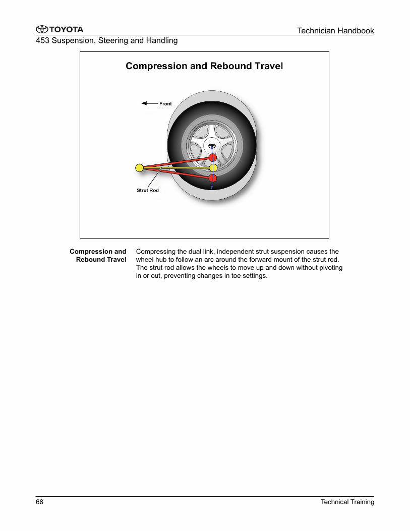
On double wishbone suspension, The location of the lower
suspension arms controls the amount of track change when the
suspension is under compression. As the suspension is compressed,
negative camber is added which improves tread contact and vehicle
handling. Compliance steer, pivoting of the rear wheels while
cornering, also improves cornering performance. When the vehicle
enters a corner, the number one suspension arm inboard bushing
deflects causing the outer wheel to pivot inward toward the direction
of the turn.
On torsion beam suspension, the toe-correct Function uses the
longitudinal and lateral forces during cornering to deform the
bushings in the trailing arms. For example on a right turn, the right
side trailing arm moves forward and the left trailing arm moves
rearward, creating a tendency for the left wheel to toe-out. With Toe-
correct bushings installed, cornering forces are applied to move the
left trailing arm towards a toe-in direction.
Toe Correct Function
Technical Training 69

453 Suspension, Steering and Handling
Technician Handbook�
Six major components or groups of components are used to
construct the suspension systems for Toyota vehicles.
1.� Springs
2.� Shock Absorbers and Struts
3.� Stabilizers or Anti-Roll Bars
4.� Control Arms, Strut Rods, Bushings, and Links
5.� Ball Joints
6.� Spindle or Axle Hub Assemblies
Suspension Components
70 Technical Training

453 Suspension, Steering and Handling
Technician Handbook�
Springs are the flexible component of a suspension system. A
vehicle’s springs serve three basic purposes:
1.� Support the weight or load of the vehicle
2.� Absorb road shock
3.� Establish the ride height of the vehicle
When a spring is compressed, the spring deforms and stores energy. As the spring returns to its original shape, or rebounds, energy is
released.
Spring rate refers to the amount of force required to deflect a spring
one inch. Softer springs have a lower spring rate and provide a soft
ride. Stiffer springs have higher spring rates. This allows the vehicle
to carry a greater load but will have a harsher ride.
Four types of springs are used on Toyota vehicles:
1.� Coil springs
2.� Leaf spring
3.� Torsion bars
4.� Pneumatic cylinders
Spring Types
Technical Training 71
453 Suspension, Steering and Handling
Technician Handbook�
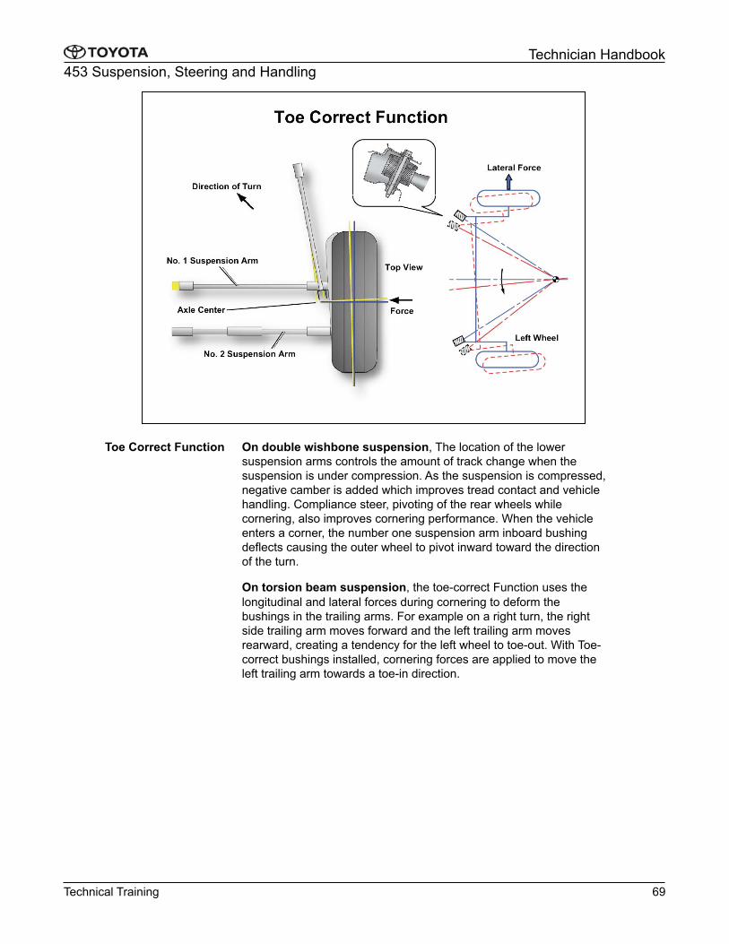
Coil springs are formed by winding spring steel wire into coils. The
spring rate is determined by the length and diameter of the steel.
Long or thin pieces of steel have a lower spring rate than short or
thick pieces. A progressive spring rate can be used to vary the rate
of spring compression. This is accomplished by changing the spacing
or diameter of the coils in the spring.
Coil Springs
72 Technical Training

453 Suspension, Steering and Handling
Technician Handbook�
Spring sag describes a reduction in the tension or elasticity of a spring.
Weak springs result in lower ride height, reduced suspension travel,
accelerated and irregular tire wear, suspension bottoming, and reduced
ride quality. The best inspection for identifying a sagging spring condition
is ride height measurement.
When measuring ride height follow these precautions:
1.� Use only measurement points specified in the Repair Manual.
2.� Correct the tire pressure and verify tire size is equivalent to OEM
before measuring.
3.� The vehicle must be on a level surface.
4.� Remove excess weight from the passenger compartment and trunk.
5.� Bounce the suspension several times before taking any
measurements.
6.� When measuring, visually inspect the rebound bumpers for excessive wear and the control arms or axle for shiny spots that would indicate
the suspension is riding on its stops.
A low value on one side of the vehicle can be caused by either the front
or rear springs. To determine which springs are sagging, raise the
vehicle at the center of the front or rear axle until the tires just leave the
ground. If the ride height on the opposite end is now correct, the springs
on the raised axle need to be replaced. Always replace both springs on
an axle, do not replace just one.
Spring Inspection
Technical Training 73

453 Suspension, Steering and Handling
Technician Handbook�
Springs of all types should be inspected for any sign of physical
damage. Significant nicks or damage to the exterior surfaces of spring
steel form stress risers. These stress risers cause the steel to work-
harden at the point of damage and can eventually lead to breakage.
Springs with large cuts or notches should be replaced.
Physical Damage
74 Technical Training
453 Suspension, Steering and Handling
Technician Handbook�
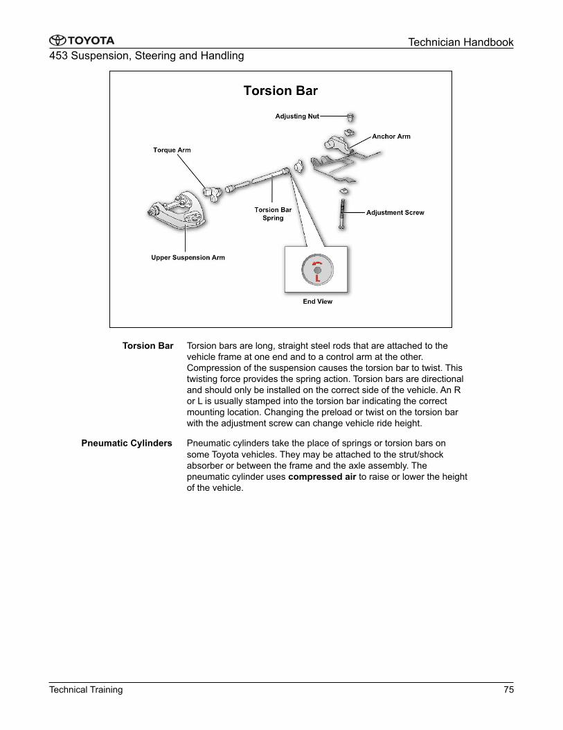
Torsion bars are long, straight steel rods that are attached to the
vehicle frame at one end and to a control arm at the other.
Compression of the suspension causes the torsion bar to twist. This
twisting force provides the spring action. Torsion bars are directional
and should only be installed on the correct side of the vehicle. An R
or L is usually stamped into the torsion bar indicating the correct
mounting location. Changing the preload or twist on the torsion bar
with the adjustment screw can change vehicle ride height.
Pneumatic cylinders take the place of springs or torsion bars on
some Toyota vehicles. They may be attached to the strut/shock
absorber or between the frame and the axle assembly. The
pneumatic cylinder uses compressed air to raise or lower the height
of the vehicle.
Torsion Bar
Pneumatic Cylinders
Technical Training 75

453 Suspension, Steering and Handling
Technician Handbook�
Leaf springs are made of a number of curved bands of spring steel,
called "leaves", stacked together. This stack is fastened together at
the center with a bolt or a rivet and also held at several places with
clips to keep the leaves from slipping out of place. Additionally leaf
springs are attached to the frame & used to locate the axle assembly.
Multi-leaf springs are most often used on the rear of trucks as they
are capable of handling greater loads.
While the vehicle is cornering, the leaf springs are designed so that
the tire turns in the direction of understeer to improve driveability.
The U-bolt seat has a right- and left-side directionality. Be sure to
observe the proper tightening sequence and torque.
Leaf Springs
Tundra Rear Leaf Springs
76 Technical Training
SERVICE TIP
453 Suspension, Steering and Handling
Technician Handbook�
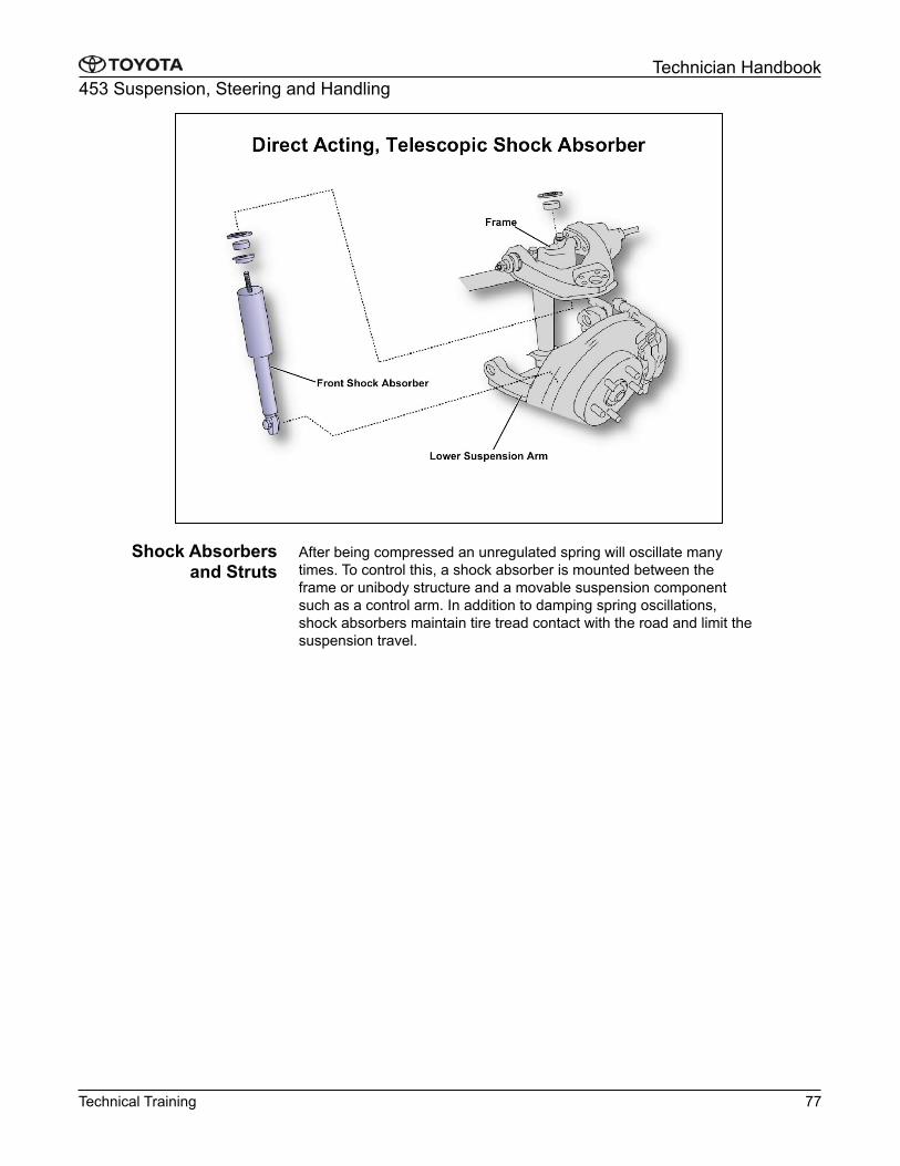
After being compressed an unregulated spring will oscillate many
times. To control this, a shock absorber is mounted between the
frame or unibody structure and a movable suspension component
such as a control arm. In addition to damping spring oscillations,
shock absorbers maintain tire tread contact with the road and limit the
suspension travel.
Shock Absorbers and Struts
Technical Training 77
453 Suspension, Steering and Handling
Technician Handbook�
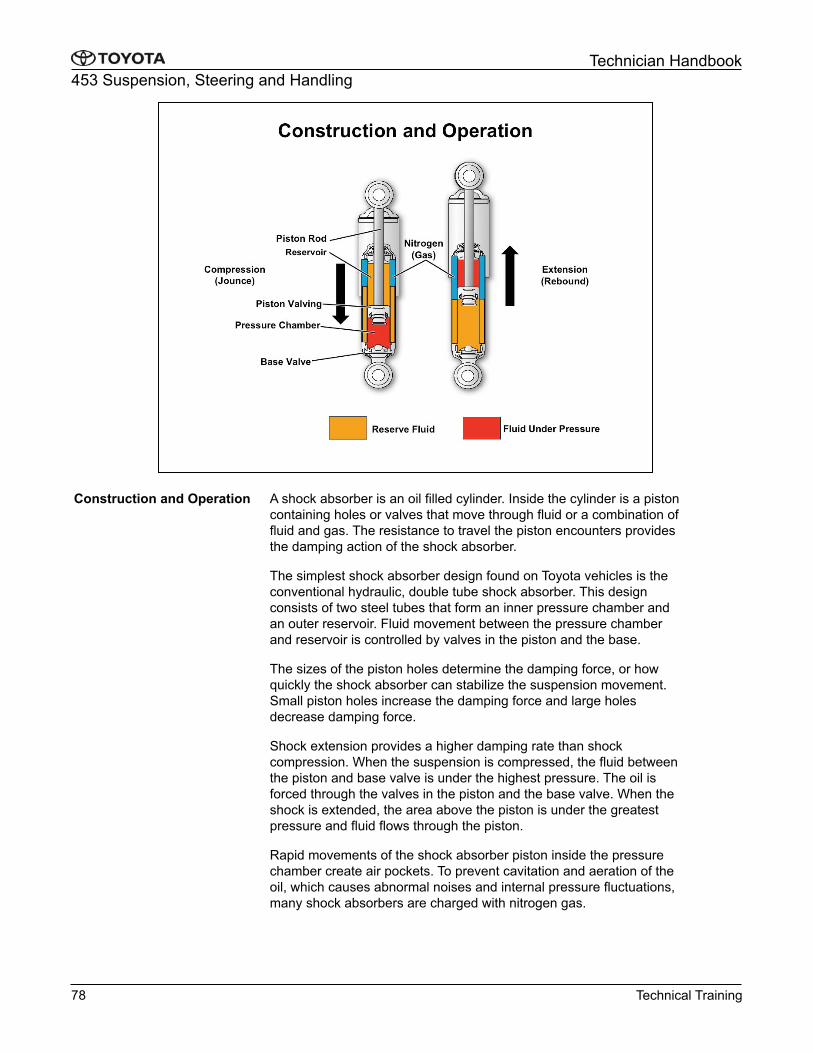
A shock absorber is an oil filled cylinder. Inside the cylinder is a piston
containing holes or valves that move through fluid or a combination of
fluid and gas. The resistance to travel the piston encounters provides
the damping action of the shock absorber.
The simplest shock absorber design found on Toyota vehicles is the
conventional hydraulic, double tube shock absorber. This design
consists of two steel tubes that form an inner pressure chamber and
an outer reservoir. Fluid movement between the pressure chamber
and reservoir is controlled by valves in the piston and the base.
The sizes of the piston holes determine the damping force, or how
quickly the shock absorber can stabilize the suspension movement.
Small piston holes increase the damping force and large holes
decrease damping force.
Shock extension provides a higher damping rate than shock
compression. When the suspension is compressed, the fluid between
the piston and base valve is under the highest pressure. The oil is
forced through the valves in the piston and the base valve. When the
shock is extended, the area above the piston is under the greatest
pressure and fluid flows through the piston.
Rapid movements of the shock absorber piston inside the pressure
chamber create air pockets. To prevent cavitation and aeration of the
oil, which causes abnormal noises and internal pressure fluctuations,
many shock absorbers are charged with nitrogen gas.
Construction and Operation
78 Technical Training

453 Suspension, Steering and Handling
Technician Handbook�
MacPherson struts combine the role of the spring, shock absorber, and
upper suspension pivot point into one unit. At the core of the strut
assembly is a shock absorber, similar to a gas filled shock absorber.
Struts use a piston rod much larger than used in a conventional shock
absorber. Since the struts serve to locate the suspension, they need a
large piston rod to absorb high lateral loads. Lateral load on the strut is
further minimized by integrating the spring seat into the strut body and
offsetting it from the piston rod. The upper spring seat is the upper strut
mount. The upper strut mount contains a strut bearing and allows the
strut body to pivot with the front wheels. This bearing is not needed in
rear suspension applications.
The condition of the upper spring seat or strut bearing may be the
source of strut assembly noise. Refer to TSB SU002-04 and others
related to strut bearing noise.
MacPherson Strut
NOTE
Technical Training 79
453 Suspension, Steering and Handling
Technician Handbook�
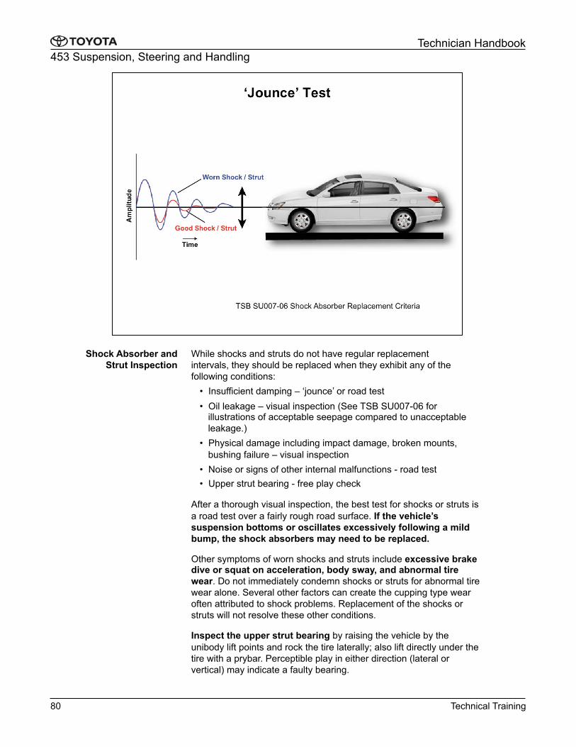
While shocks and struts do not have regular replacement
intervals, they should be replaced when they exhibit any of the
following conditions:
•� Insufficient damping – ‘jounce’ or road test
•� Oil leakage – visual inspection (See TSB SU007-06 for illustrations of acceptable seepage compared to unacceptable
leakage.)
•� Physical damage including impact damage, broken mounts,
bushing failure – visual inspection
•� Noise or signs of other internal malfunctions - road test
•� Upper strut bearing - free play check
After a thorough visual inspection, the best test for shocks or struts is
a road test over a fairly rough road surface. If the vehicle’s
suspension bottoms or oscillates excessively following a mild
bump, the shock absorbers may need to be replaced.
Other symptoms of worn shocks and struts include excessive brake dive or squat on acceleration, body sway, and abnormal tire
wear. Do not immediately condemn shocks or struts for abnormal tire
wear alone. Several other factors can create the cupping type wear
often attributed to shock problems. Replacement of the shocks or
struts will not resolve these other conditions.
Inspect the upper strut bearing by raising the vehicle by the
unibody lift points and rock the tire laterally; also lift directly under the
tire with a prybar. Perceptible play in either direction (lateral or
vertical) may indicate a faulty bearing.
Shock Absorber and
Strut Inspection
80 Technical Training
453 Suspension, Steering and Handling
Technician Handbook�
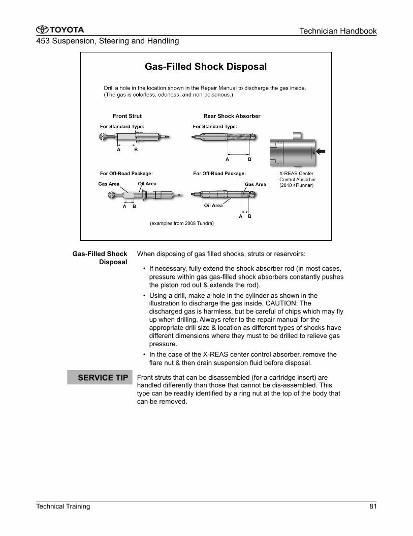
When disposing of gas filled shocks, struts or reservoirs:
•� If necessary, fully extend the shock absorber rod (in most cases,
pressure within gas gas-filled shock absorbers constantly pushes
the piston rod out & extends the rod).
•� Using a drill, make a hole in the cylinder as shown in the illustration to discharge the gas inside. CAUTION: The
discharged gas is harmless, but be careful of chips which may fly
up when drilling. Always refer to the repair manual for the
appropriate drill size & location as different types of shocks have
different dimensions where they must to be drilled to relieve gas
pressure.
•� In the case of the X-REAS center control absorber, remove the
flare nut & then drain suspension fluid before disposal.
Front struts that can be disassembled (for a cartridge insert) are handled differently than those that cannot be dis-assembled. This
type can be readily identified by a ring nut at the top of the body that
can be removed.
Gas-Filled Shock
Disposal
Technical Training 81
SERVICE TIP

453 Suspension, Steering and Handling
Technician Handbook�
When a vehicle turns, the inside wheel tries to lift up and forces the
outside wheel down and outward. A stabilizer bar is used to control
this action. The stabilizer bar, or anti-roll bar, is mounted transversely
to the body, between the right and left suspension arms. Stabilizer
bars are used in front and rear suspensions. They use the same
operating principles as a torsion bar. During a turn the stabilizer bar
twists, like a torsion bar, resisting body roll which maintains a greater
vehicle load on the inside wheel.
The primary inspection item for stabilizer bars is the condition of the
bushings and links. Inspect for deterioration, damage, and excessive
play. Many hard to find suspension noises can be traced to the
stabilizer bar bushings. Remember when installing new bushings,
torque the fasteners with the vehicle at its normal ride height. Also
stabilizer bar links should be equal lengths on both sides of the car to
prevent preloading the bar.
Stabilizer Bars
Stabilizer Bar Inspection
82 Technical Training

453 Suspension, Steering and Handling
Technician Handbook�
The function of the control arms, links, and strut rods is to locate the
wheel hub or steering knuckle. The suspension geometry is
determined by the placement of these components. This establishes
the vehicle’s overall handling traits. These components contain
rubber bushings that allow the suspension to move and absorb minor
road shocks and vibrations. Bushings with different flexibility are used
to achieve certain ride quality or vehicle handling characteristics.
Inspection of control arms, bushings, and links primarily involves
visually checking for physical damage, distortion, and rubber
deterioration. Worn or damaged bushings may cause changes in
alignment geometry that result in abnormal or irregular tire wear.
Clunking or thumping noises that can be heard during acceleration or
braking often indicate worn bushings as well.
When installing components with bushings, such as control arms and
stabilizer bars, torque the components with the suspension at normal
ride height.
Most rubber bushings used on Toyota vehicles do not require
lubrication. Applying petroleum lubricants to these bushings
accelerates their deterioration.
Control Arms, Strut Rods, Links and
Bushings
Control Arms, Strut Rods,
Links and Bushings
Inspection
NOTE
Technical Training 83
453 Suspension, Steering and Handling
Technician Handbook�
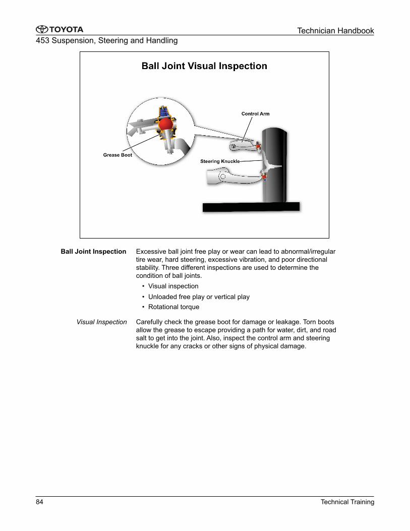
Excessive ball joint free play or wear can lead to abnormal/irregular
tire wear, hard steering, excessive vibration, and poor directional
stability. Three different inspections are used to determine the
condition of ball joints.
•� Visual inspection
•� Unloaded free play or vertical play
•� Rotational torque
Carefully check the grease boot for damage or leakage. Torn boots
allow the grease to escape providing a path for water, dirt, and road
salt to get into the joint. Also, inspect the control arm and steering
knuckle for any cracks or other signs of physical damage.
Ball Joint Inspection
Visual Inspection
84 Technical Training
453 Suspension, Steering and Handling
Technician Handbook�
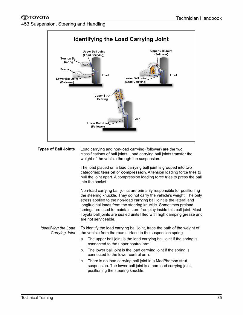
Load carrying and non-load carrying (follower) are the two
classifications of ball joints. Load carrying ball joints transfer the
weight of the vehicle through the suspension.
The load placed on a load carrying ball joint is grouped into two
categories: tension or compression. A tension loading force tries to
pull the joint apart. A compression loading force tries to press the ball
into the socket.
Non-load carrying ball joints are primarily responsible for positioning
the steering knuckle. They do not carry the vehicle’s weight. The only
stress applied to the non-load carrying ball joint is the lateral and
longitudinal loads from the steering knuckle. Sometimes preload
springs are used to maintain zero free play inside this ball joint. Most
Toyota ball joints are sealed units filled with high damping grease and
are not serviceable.
To identify the load carrying ball joint, trace the path of the weight of
the vehicle from the road surface to the suspension spring.
a.� The upper ball joint is the load carrying ball joint if the spring is
connected to the upper control arm.
b.� The lower ball joint is the load carrying joint if the spring is connected to the lower control arm.
c.� There is no load carrying ball joint in a MacPherson strut
suspension. The lower ball joint is a non-load carrying joint,
positioning the steering knuckle.
Types of Ball Joints
Identifying the Load
Carrying Joint
Technical Training 85
453 Suspension, Steering and Handling
Technician Handbook�
Regardless of vehicle model or type of ball joint, a visual inspection
should be performed anytime the vehicle is serviced. When further
inspection is necessary, the Repair Manual identifies which
inspection method should be used to verify the internal condition of
the ball joints on a particular vehicle.
Pay particular attention to load carrying joints as they will generally
exhibit more wear than follower joints. Also note that if one load
carrying joint is identified as faulty, the matching joint on the other
side of the vehicle should be carefully inspected as it is likely to be
worn out as well.
Identifying the Load
Carrying Joint (cont’d)
86 Technical Training

453 Suspension, Steering and Handling
Technician Handbook�
The recommended ball joint inspection method for many early
vehicles is a measurement of joint free play or clearance. Most load
carrying joints on these models allow a minimal amount of vertical
free play. As the joint wears; the clearance increases and may
become excessive.
Inspection of free play requires a load carrying ball joint be unloaded.
The amount of play between the steering knuckle and control arm is
then measured with a dial indicator. To unload the joint, the vehicle is
raised by either the lower control arm or the frame. Placement of the
jack depends upon the location of the spring and load carrying joint.
When performing this check, unload both load carrying joints on the vehicle at the same time to prevent the stabilizer bar from twisting
and preloading the joint. A dial indicator should be placed between
the suspension arm and steering knuckle to measure the amount of
free play.
Be sure to refer to the Repair Manual for the vehicle you are
inspecting to find specifications and the exact procedure. Most
models require the front wheels be pointed straight ahead and some
models require the brake pedal to be depressed.
Unloaded Free Play
Technical Training 87
453 Suspension, Steering and Handling
Technician Handbook�
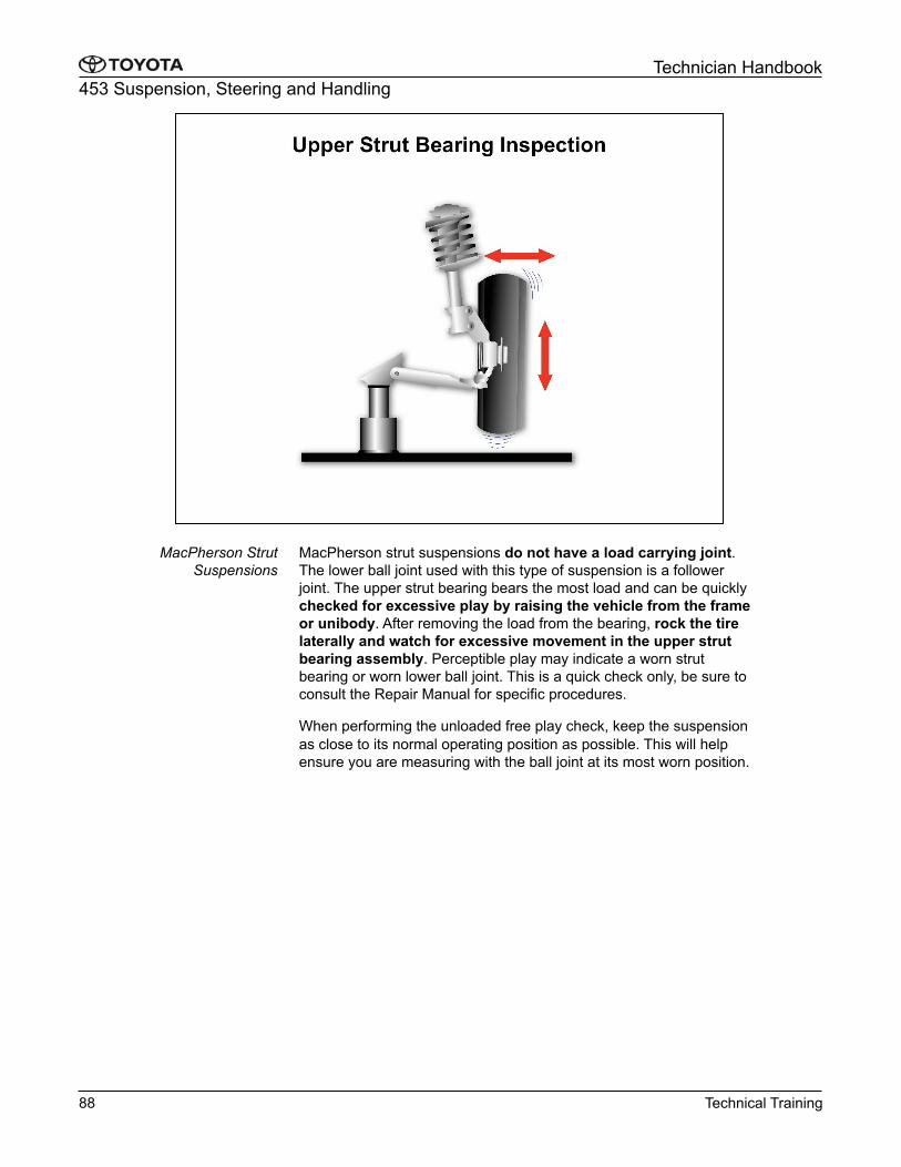
MacPherson strut suspensions do not have a load carrying joint.
The lower ball joint used with this type of suspension is a follower
joint. The upper strut bearing bears the most load and can be quickly
checked for excessive play by raising the vehicle from the frame
or unibody. After removing the load from the bearing, rock the tire
laterally and watch for excessive movement in the upper strut
bearing assembly. Perceptible play may indicate a worn strut
bearing or worn lower ball joint. This is a quick check only, be sure to
consult the Repair Manual for specific procedures.
When performing the unloaded free play check, keep the suspension
as close to its normal operating position as possible. This will help
ensure you are measuring with the ball joint at its most worn position.
MacPherson Strut
Suspensions
88 Technical Training

453 Suspension, Steering and Handling
Technician Handbook�
The ball joint inspection method recommended for most late model
Toyota vehicles is a rotational torque check. Many current model ball
joints are designed with a preload spring. These designs are more
difficult to perform a vertical play inspection and should be removed
to inspect. Be sure to use the correct puller to break the taper when
removing the joint and do not tear the grease boot.
Once out of the car, the ball joint nut is installed onto the stud and a
dial or beam type torque wrench is used to measure the amount of
force required to rotate the ball within the socket. Rotate the stud
slowly, about one turn every 2-4 seconds, and note the torque
reading after every fifth turn.
If the turning torque is found to be excessive, the ball joint is too tight and should be replaced. Conversely, if the torque reading is too low,
the joint is excessively worn and should be replaced. Refer to the
torque specifications in the appropriate Repair Manual.
Rotational Torque Inspection
Technical Training 89
453 Suspension, Steering and Handling
Technician Handbook�
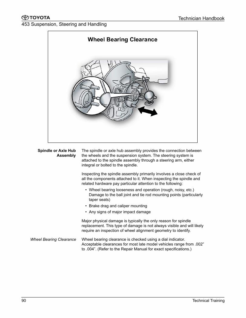
The spindle or axle hub assembly provides the connection between
the wheels and the suspension system. The steering system is
attached to the spindle assembly through a steering arm, either
integral or bolted to the spindle.
Inspecting the spindle assembly primarily involves a close check of
all the components attached to it. When inspecting the spindle and
related hardware pay particular attention to the following:
•� Wheel bearing looseness and operation (rough, noisy, etc.)
Damage to the ball joint and tie rod mounting points (particularly
taper seats)
•� Brake drag and caliper mounting
•� Any signs of major impact damage
Major physical damage is typically the only reason for spindle
replacement. This type of damage is not always visible and will likely
require an inspection of wheel alignment geometry to identify.
Wheel bearing clearance is checked using a dial indicator.
Acceptable clearances for most late model vehicles range from .002”
to .004”. (Refer to the Repair Manual for exact specifications.)
Spindle or Axle Hub
Assembly
Wheel Bearing Clearance
90 Technical Training