Embed Size (px)
Citation preview
MIT OpenCourseWare http://ocw.mit.edu
4.510 Digital Design Fabrication Fall 2008
For information about citing these materials or our Terms of Use, visit: http://ocw.mit.edu/terms.
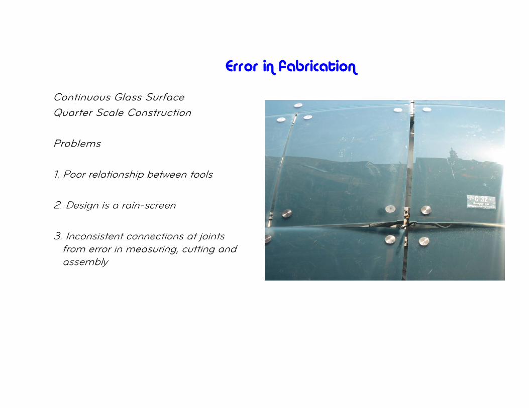
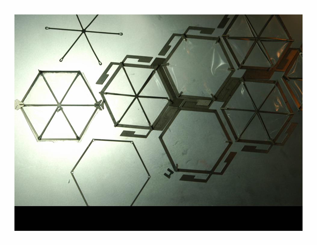
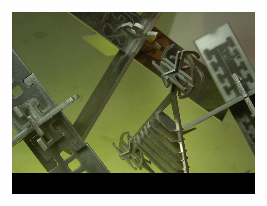
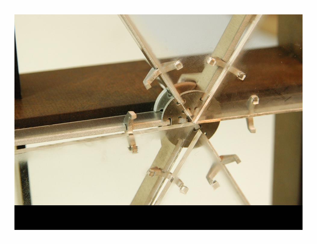
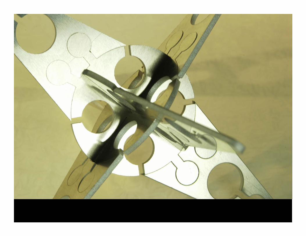
Error in fabrication
Continuous Glass Surface Quarter Scale Construction
Problems
1. Poor relationship between tools
2. Design is a rain-screen
3. Inconsistent connections at joints from error in measuring, cutting and assembly
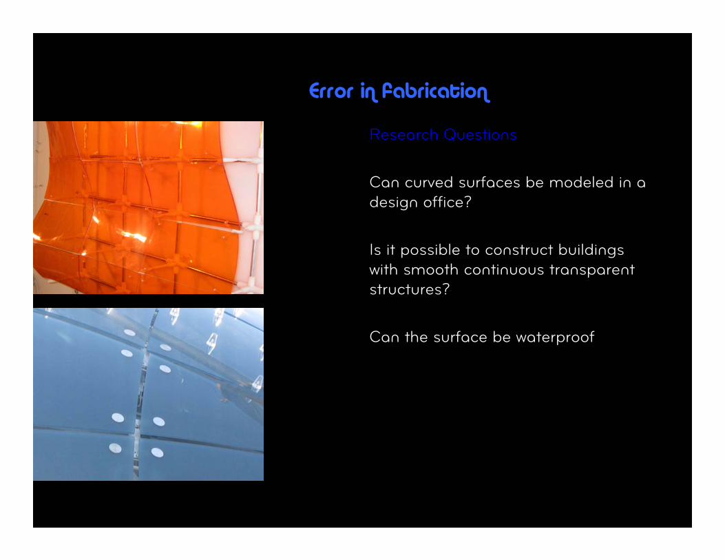
Error in fabrication
Research Questions
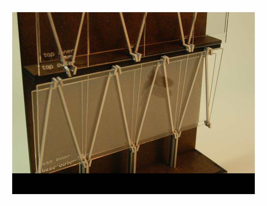
Can curved surfaces be modeled in a design office?
Is it possible to construct buildings with smooth continuous transparent structures?
Can the surface be waterproof
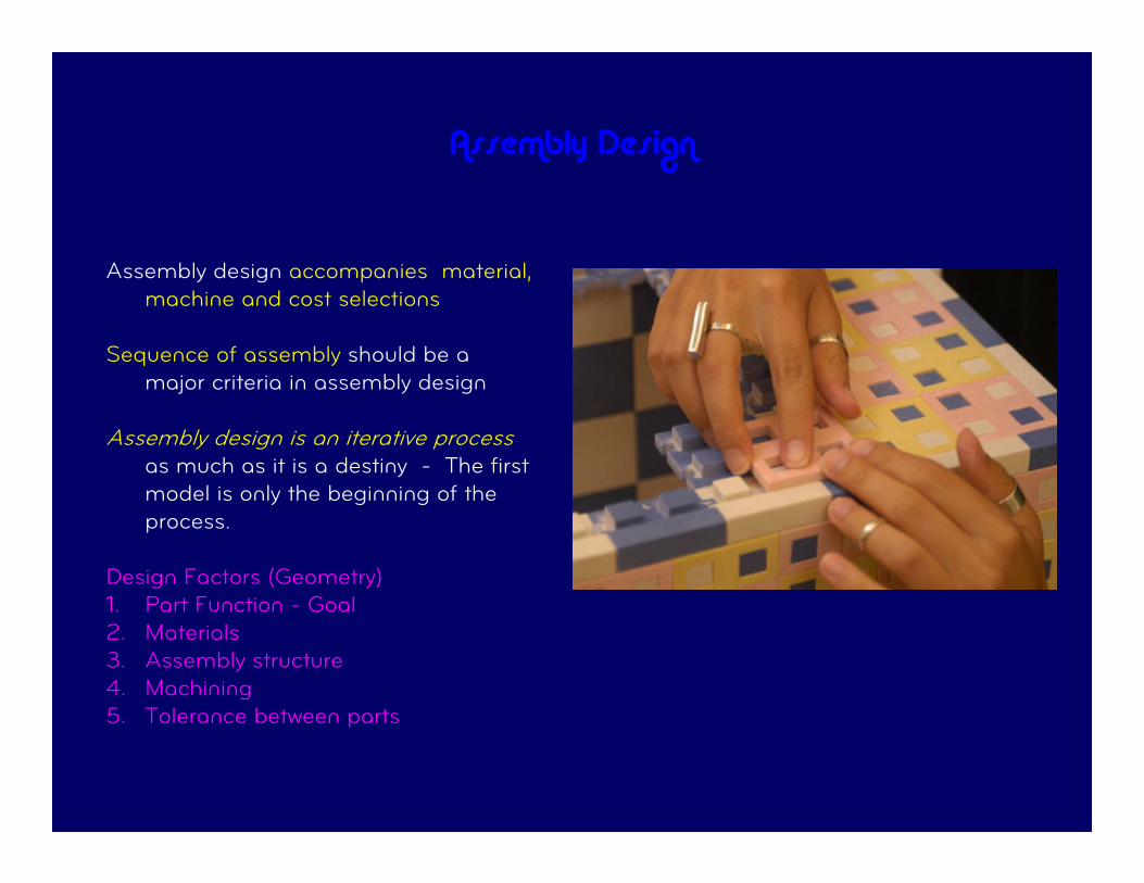
Assembly Design
Assembly design accompanies material, machine and cost selections
Sequence of assembly should be a major criteria in assembly design
Assembly design is an iterative process as much as it is a destiny - The first model is only the beginning of the process.
Design Factors (Geometry) 1. Part Function - Goal 2. Materials 3. Assembly structure 4. Machining 5. Tolerance between parts
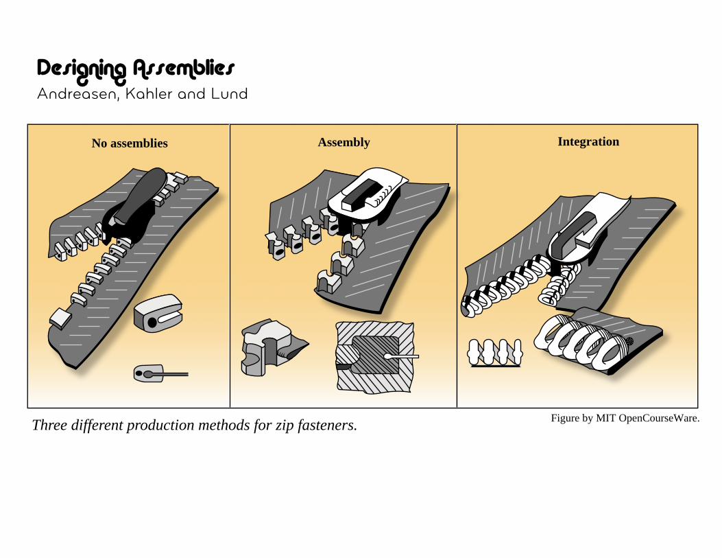
Designing Assemblies Andreasen, Kahler and Lund
Making a Zipper No assemblies Assembly Integration
Three different production methods for zip fasteners. Figure by MIT OpenCourseWare.
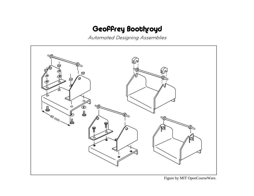
Geoffrey Boothroyd Automated Designing Assemblies
48 mm
Figure by MIT OpenCourseWare.

Factors in Automated Assembly
• Automate assembly process using machines that assemble parts on a line
• Increase productivity and reduce cost
• Build a more consistent product with higher reliability
48 mm
1
0.9
0.8
0.7
0.6
0.5
0.4
0.3
0.2
0.1
024 8 4 2
Number of parts
Ass
embl
y co
st ($
)
ManualRobotAutomatic
Annual Production Volumes:
Robotic - 200,000Automatic - 2,400,000
Figure by MIT OpenCourseWare.
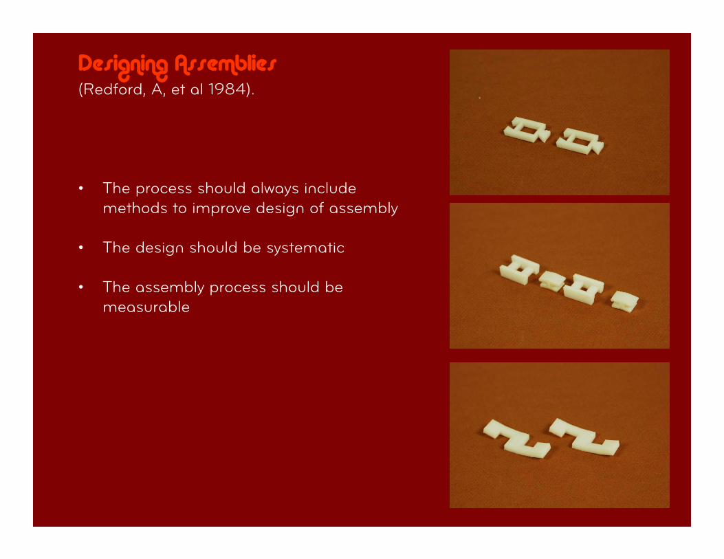
Designing Assemblies (Redford, A, et al 1984).
• The process should always include methods to improve design of assembly
• The design should be systematic
• The assembly process should be measurable
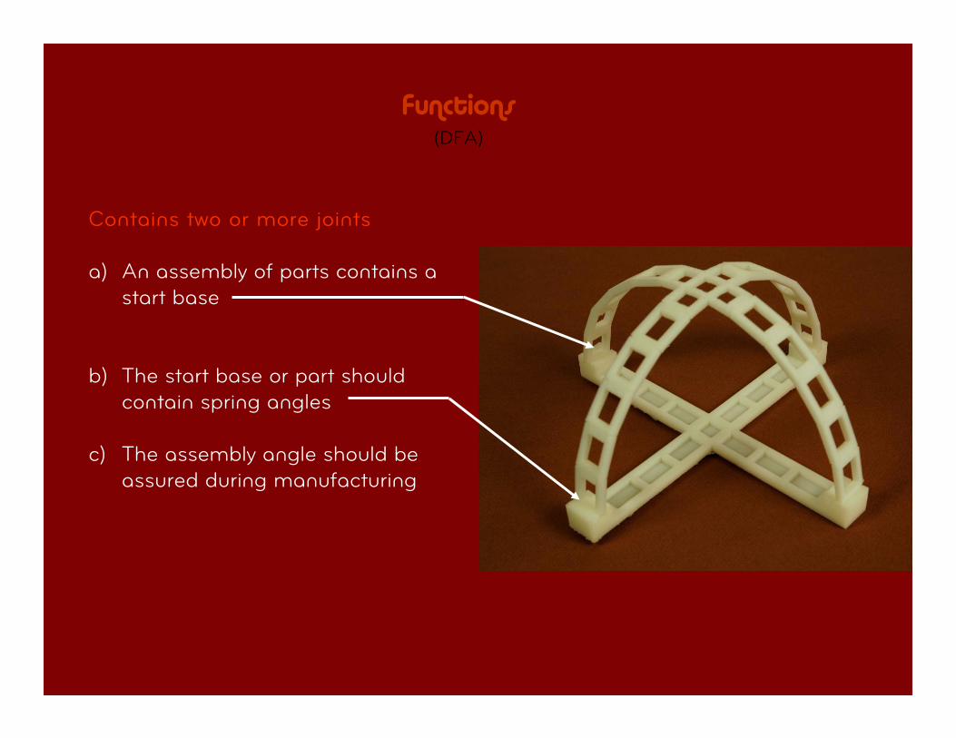
Functions (DFA)
Contains two or more joints
a) An assembly of parts contains a start base
b) The start base or part should contain spring angles
c) The assembly angle should be assured during manufacturing
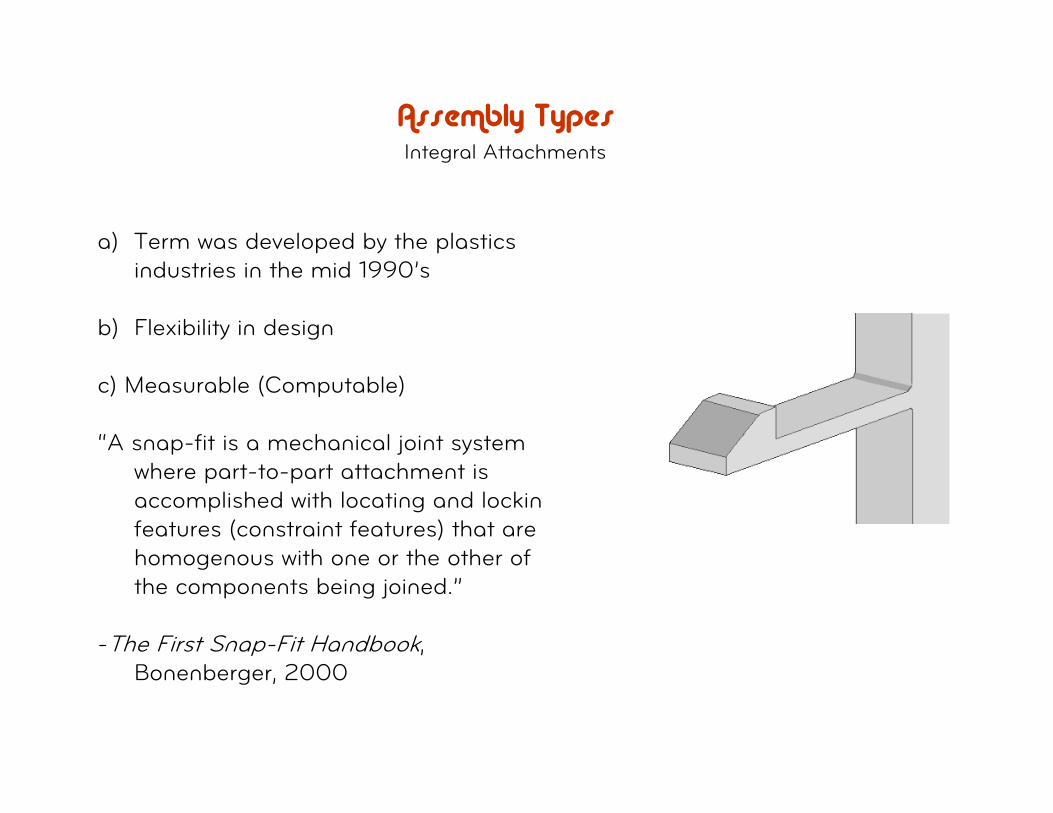
Assembly Types Integral Attachments
a) Term was developed by the plastics industries in the mid 1990’s
b) Flexibility in design
c) Measurable (Computable)
“A snap-fit is a mechanical joint system where part-to-part attachment is accomplished with locating and locking features (constraint features) that are homogenous with one or the other of the components being joined.”
-The First Snap-Fit Handbook, Bonenberger, 2000
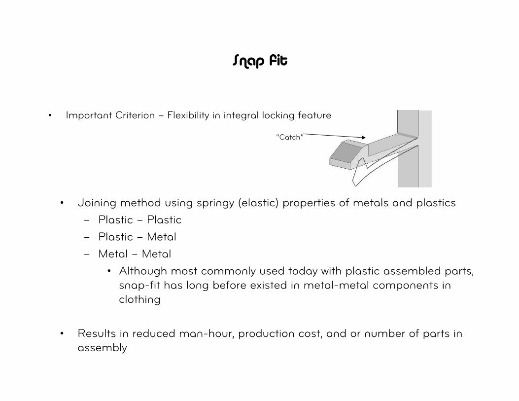
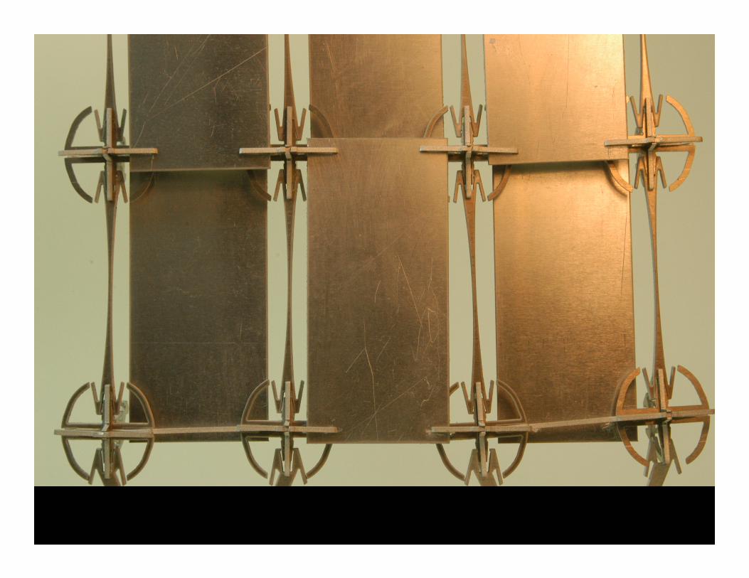
Snap fit
• Important Criterion – Flexibility in integral locking feature
“Catch”
• Joining method using springy (elastic) properties of metals and plastics
– Plastic – Plastic
– Plastic – Metal
– Metal – Metal
• Although most commonly used today with plastic assembled parts, snap-fit has long before existed in metal-metal components in clothing
• Results in reduced man-hour, production cost, and or number of parts in assembly
Snap fit examples
• Toys
• Small Appliances
• Automotive
• Electronic Fields
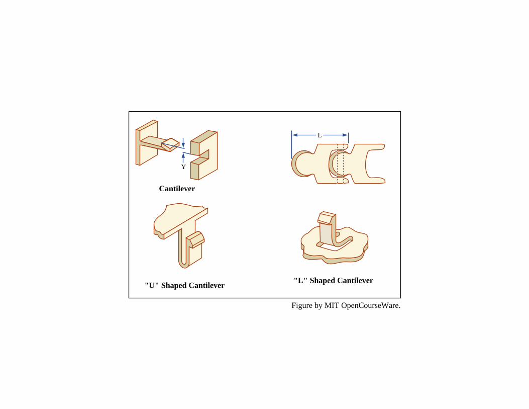
Y
L
Cantilever
"L" Shaped Cantilever"U" Shaped Cantilever
Figure by MIT OpenCourseWare.
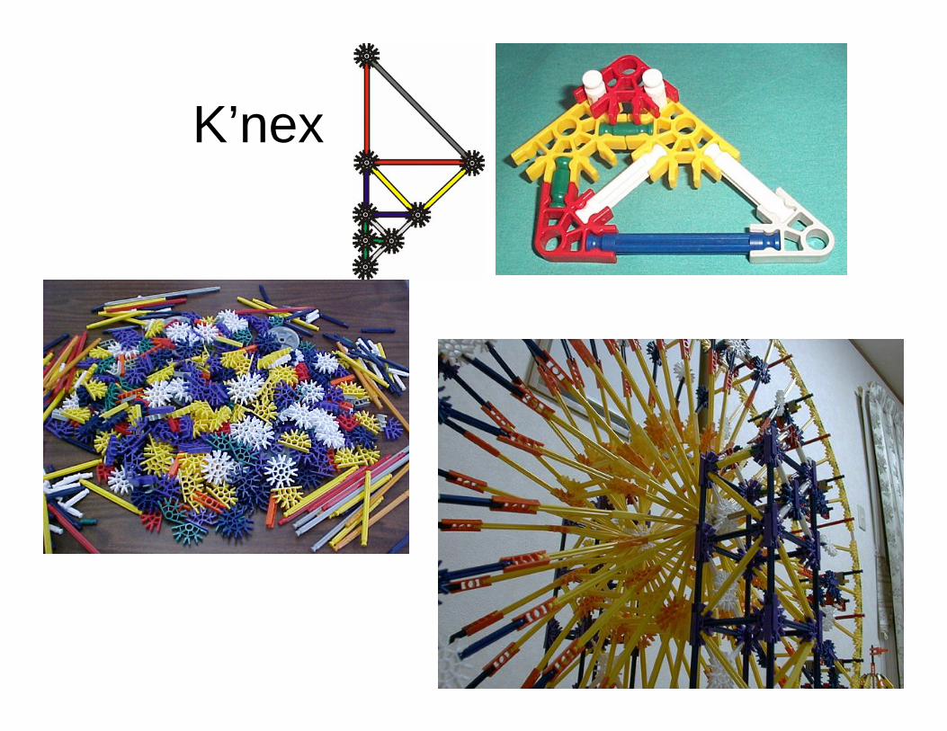
K’nex
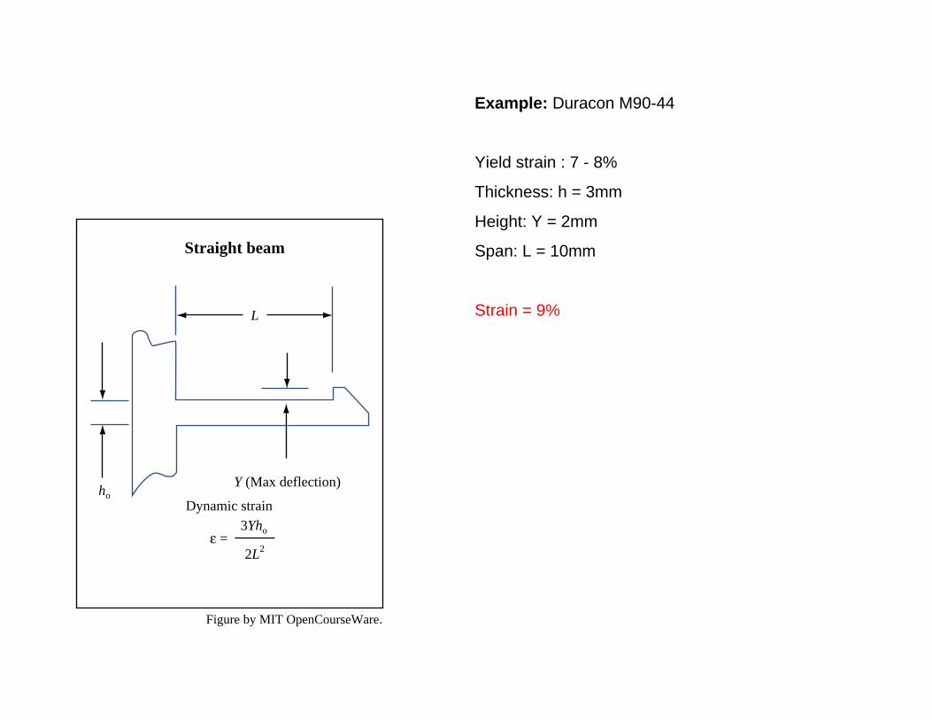
Example: Duracon M90-44
Yield strain : 7 - 8%
Thickness: h = 3mm
Height: Y = 2mm
Span: L = 10mm
Strain = 9%
Y (Max deflection)
Straight beam
Dynamic strain3Yho
ho
2L2ε =
L
Figure by MIT OpenCourseWare.
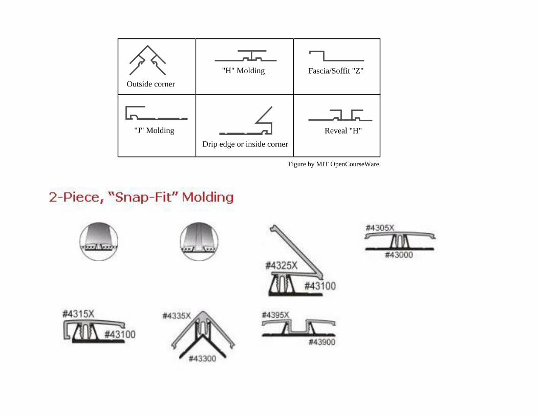
Fascia/Soffit "Z"
"J" Molding
Outside corner
Drip edge or inside cornerReveal "H"
"H" Molding
Figure by MIT OpenCourseWare.