Embed Size (px)
DESCRIPTION
WING SPAR
Citation preview

1CADES Proprietary Confidential
Design of Front and Rear Spars for The
Trainer Aircraft Wing.
2CADES Proprietary Confidential
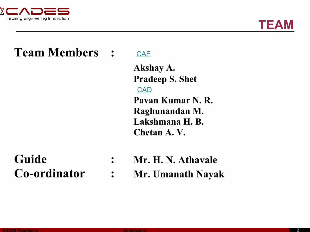
TEAM
Team Members :Akshay A. Pradeep S. Shet
Pavan Kumar N. R.Raghunandan M.Lakshmana H. B.Chetan A. V.
Guide : Mr. H. N. Athavale
Co-ordinator : Mr. Umanath Nayak
CAE
CAD
3CADES Proprietary Confidential
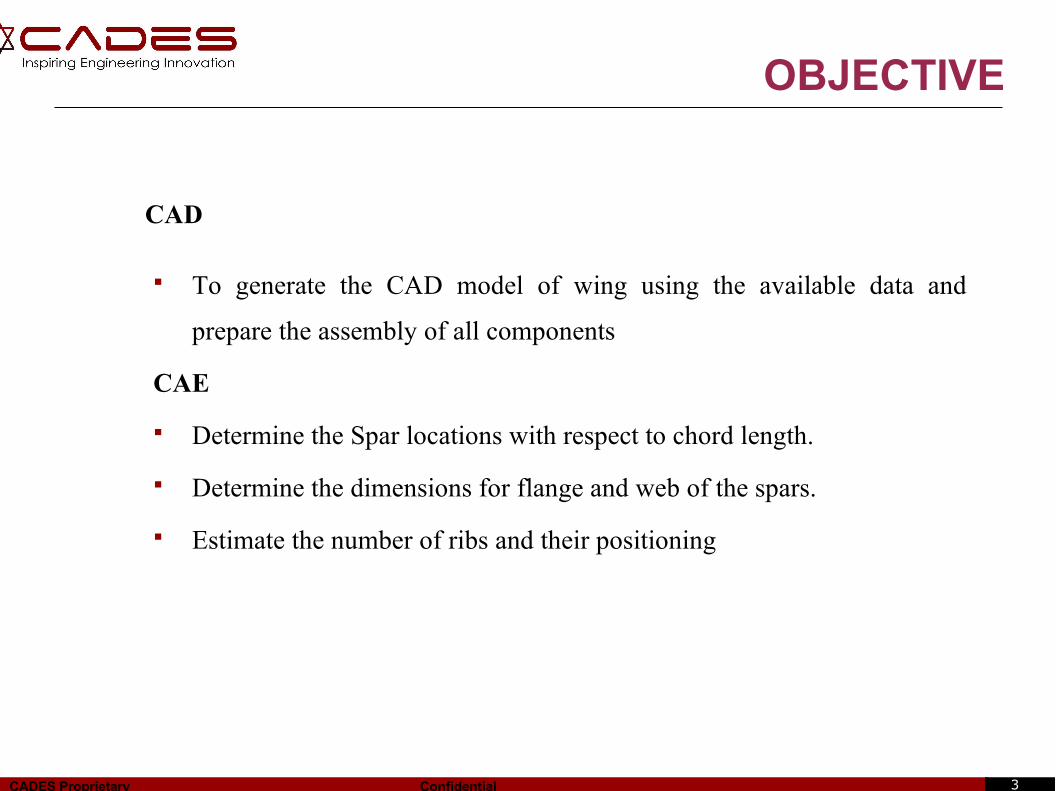
OBJECTIVE
CAD
To generate the CAD model of wing using the available data and
prepare the assembly of all components
CAE
Determine the Spar locations with respect to chord length.
Determine the dimensions for flange and web of the spars.
Estimate the number of ribs and their positioning
4CADES Proprietary Confidential
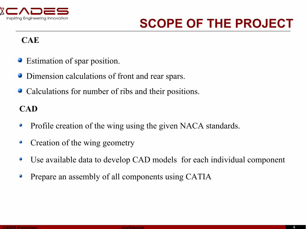
SCOPE OF THE PROJECT
Estimation of spar position.
Dimension calculations of front and rear spars.
Calculations for number of ribs and their positions.
CAD
Profile creation of the wing using the given NACA standards.
Creation of the wing geometry
Use available data to develop CAD models for each individual component
Prepare an assembly of all components using CATIA
CAE
5CADES Proprietary Confidential
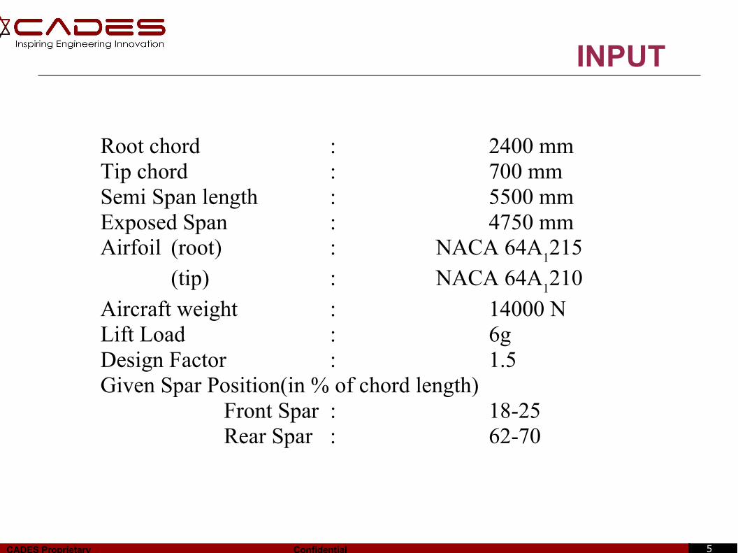
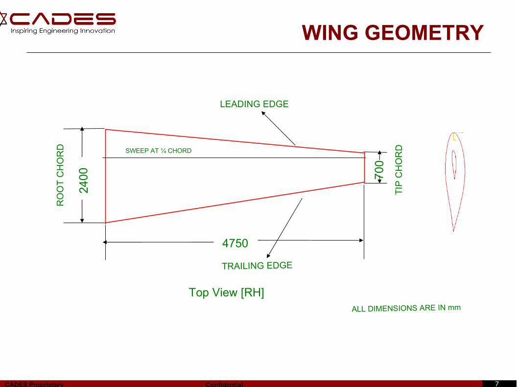
Root chord : 2400 mmTip chord : 700 mmSemi Span length : 5500 mmExposed Span : 4750 mmAirfoil (root) : NACA 64A
1215
(tip) : NACA 64A1210
Aircraft weight : 14000 NLift Load : 6gDesign Factor : 1.5Given Spar Position(in % of chord length)
Front Spar : 18-25Rear Spar : 62-70
INPUT
6CADES Proprietary Confidential
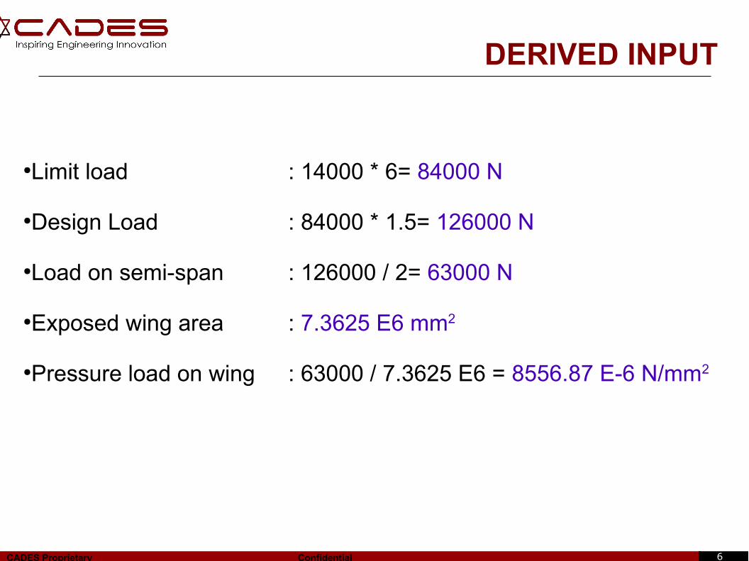
DERIVED INPUT
●Limit load : 14000 * 6= 84000 N
●Design Load : 84000 * 1.5= 126000 N
●Load on semi-span : 126000 / 2= 63000 N
●Exposed wing area : 7.3625 E6 mm2
●Pressure load on wing : 63000 / 7.3625 E6 = 8556.87 E-6 N/mm2
7CADES Proprietary Confidential
WING GEOMETRY
ALL DIMENSIONS ARE IN mm
RO
OT
CH
OR
D SWEEP AT ¼ CHORD
4750
700
2400
TIP
CH
OR
D
LEADING EDGE
TRAILING EDGE
Top View [RH]
8CADES Proprietary Confidential
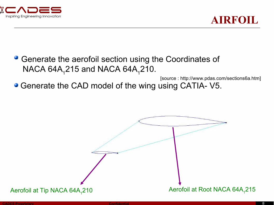
AIRFOIL
Generate the aerofoil section using the Coordinates of NACA 64A
1215 and NACA 64A
1210.
[source : http://www.pdas.com/sections6a.htm]
Generate the CAD model of the wing using CATIA- V5.
Aerofoil at Root NACA 64A1215Aerofoil at Tip NACA 64A
1210
9CADES Proprietary Confidential
DESIGN PROCEDURE
Calculation of the Shear force, Bending moment & Torsion for the
given load.
Calculation of load distribution between the front and rear spar.
Estimation of spar positions.
Generation of CAD Model and Drafting.
10CADES Proprietary Confidential
DESIGN PROCEDURE
Divide the wing area into number of divisions.
Calculate the chord length at each section.
Determine the C.G of each area.
Calculate the shear force, bending moment and Torque at the respective
sections.
Shear force =pressure*area.
Bending moment=shear force*CG distance.
Torque = Shear force*Distance b/w CG and CP.
11CADES Proprietary Confidential
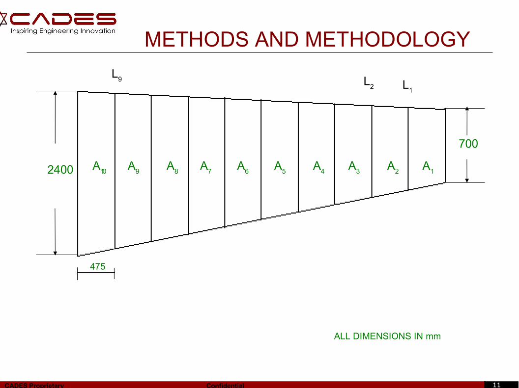
METHODS AND METHODOLOGY
A10
A9
A8
A7
A6
A5
A4
A3
A2
A1
475
2400
700
ALL DIMENSIONS IN mm
L1
L2
L9
12CADES Proprietary Confidential
Chord Length, L1= L
root-((L
root-L
tip) / S) * x
At section 2, L1 = 2400-((2400-700)/4750)*4275
L1 = 870 mm
Area of Trapezium, A1 = 0.5*(L
1+L
tip)*h
A1 = 0.5*(870+700)*475
A1 = 373 E3 mm2
CG of Trapezoid Section = h/3*((Ltip
+2L1)/(L
tip+L
1))
CG=475/3*((700+2*870)/(700+870)) CG = 246 mm from L
tip
DESIGN PROCEDURE
S
xLroot
Ltip
L1
A1
h
13CADES Proprietary Confidential
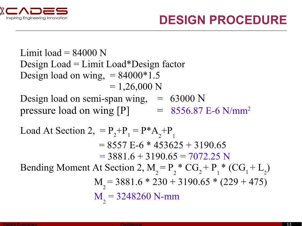
DESIGN PROCEDURE
Limit load = 84000 NDesign Load = Limit Load*Design factorDesign load on wing, = 84000*1.5 = 1,26,000 NDesign load on semi-span wing, = 63000 Npressure load on wing [P] = 8556.87 E-6 N/mm2
Load At Section 2, = P2+P
1 = P*A
2+P
1
= 8557 E-6 * 453625 + 3190.65 = 3881.6 + 3190.65 = 7072.25 N
Bending Moment At Section 2, M2 = P
2 * CG
2 + P
1 * (CG
1 + L
2)
M2 = 3881.6 * 230 + 3190.65 * (229 + 475)
M2 = 3248260 N-mm
14CADES Proprietary Confidential
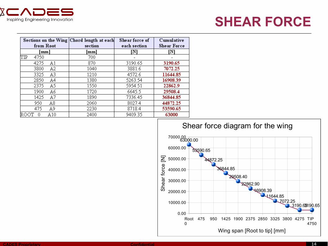
SHEAR FORCE
Root 0
475 950 1425 1900 2375 2850 3325 3800 4275 TIP 4750
0.00
10000.00
20000.00
30000.00
40000.00
50000.00
60000.00
70000.0063000.00
53590.65
44872.25
36844.85
29508.40
22862.90
16908.3911644.85
7072.253190.653190.65
Shear force diagram for the wing
Wing span [Root to tip] [mm]
Sh
ea
r fo
rce
[N
]
15CADES Proprietary Confidential
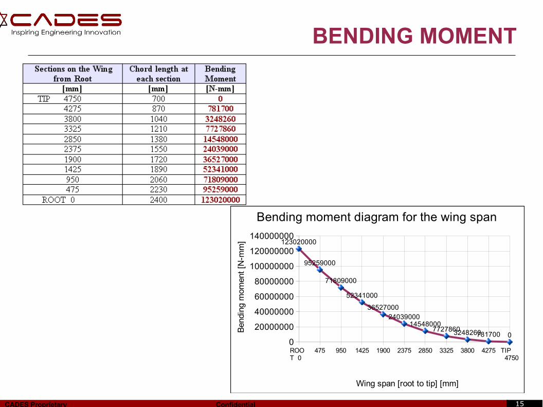
BENDING MOMENT
ROOT 0
475 950 1425 1900 2375 2850 3325 3800 4275 TIP 4750
0
20000000
40000000
60000000
80000000
100000000
120000000
140000000123020000
95259000
71809000
52341000
3652700024039000
1454800077278603248260781700 0
Bending moment diagram for the wing span
Wing span [root to tip] [mm]
Ben
ding
mo m
ent
[N-m
m]
16CADES Proprietary Confidential
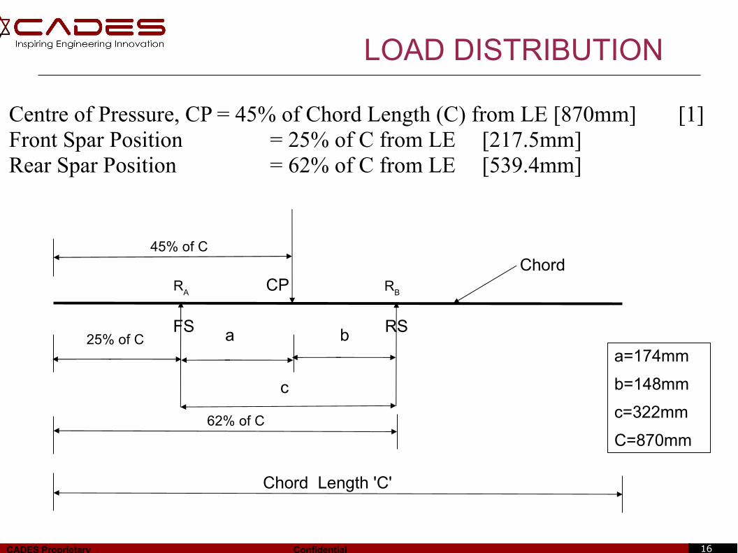
LOAD DISTRIBUTION
Centre of Pressure, CP = 45% of Chord Length (C) from LE [870mm] [1]Front Spar Position = 25% of C from LE [217.5mm]Rear Spar Position = 62% of C from LE [539.4mm]
Chord Length 'C'
45% of C
25% of C a b
c
62% of C
RA R
B
FS RS
ChordCP
a=174mm
b=148mm
c=322mm
C=870mm
17CADES Proprietary Confidential
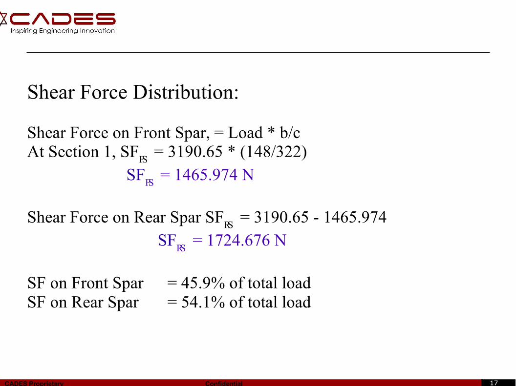
Shear Force Distribution:
Shear Force on Front Spar, = Load * b/cAt Section 1, SF
FS = 3190.65 * (148/322)
SFFS
= 1465.974 N
Shear Force on Rear Spar SFRS
= 3190.65 - 1465.974 SF
RS = 1724.676 N
SF on Front Spar = 45.9% of total loadSF on Rear Spar = 54.1% of total load
18CADES Proprietary Confidential
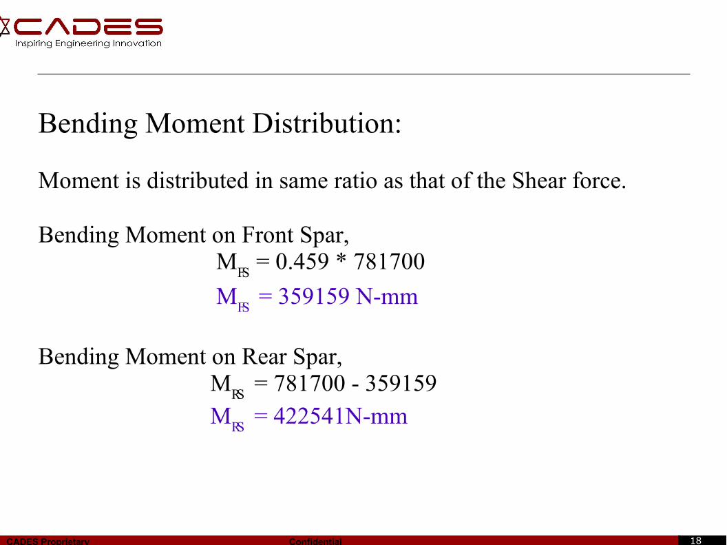
Bending Moment Distribution:
Moment is distributed in same ratio as that of the Shear force.
Bending Moment on Front Spar, M
FS = 0.459 * 781700
MFS
= 359159 N-mm
Bending Moment on Rear Spar, M
RS = 781700 - 359159
MRS
= 422541N-mm
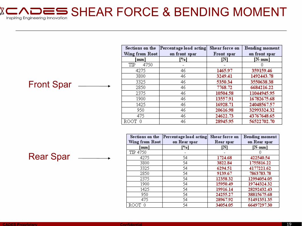
19CADES Proprietary Confidential
Front Spar
Rear Spar
SHEAR FORCE & BENDING MOMENT
20CADES Proprietary Confidential
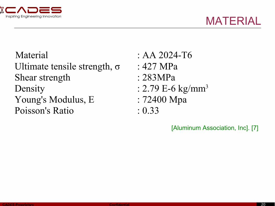
MATERIAL
Material : AA 2024-T6 Ultimate tensile strength, σ : 427 MPa Shear strength : 283MPa Density : 2.79 E-6 kg/mm3
Young's Modulus, E : 72400 Mpa Poisson's Ratio : 0.33
[Aluminum Association, Inc]. [7]
21CADES Proprietary Confidential
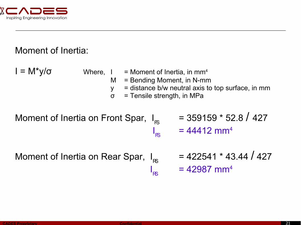
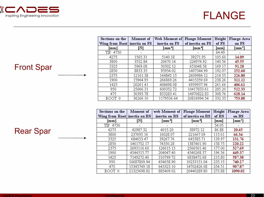
Moment of Inertia:
I = M*y/σ Where, I = Moment of Inertia, in mm4
M = Bending Moment, in N-mmy = distance b/w neutral axis to top surface, in mmσ = Tensile strength, in MPa
Moment of Inertia on Front Spar, IFS
= 359159 * 52.8 / 427
IFS
= 44412 mm4
Moment of Inertia on Rear Spar, IRS
= 422541 * 43.44 / 427
IRS
= 42987 mm4
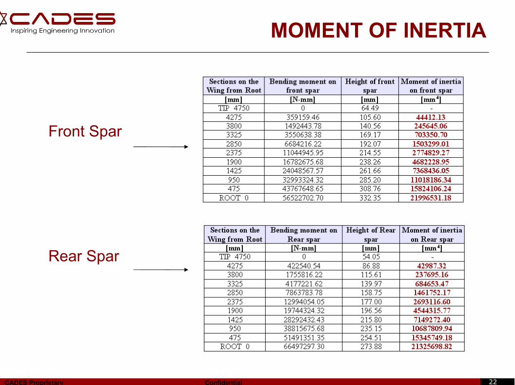
22CADES Proprietary Confidential
MOMENT OF INERTIA
Front Spar
Rear Spar
23CADES Proprietary Confidential
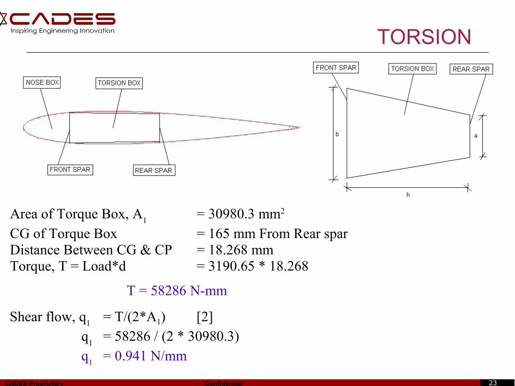
TORSION
Area of Torque Box, A1 = 30980.3 mm2
CG of Torque Box = 165 mm From Rear sparDistance Between CG & CP = 18.268 mmTorque, T = Load*d = 3190.65 * 18.268
T = 58286 N-mm
Shear flow, q1 = T/(2*A1) [2]
q1
= 58286 / (2 * 30980.3) q
1= 0.941 N/mm
24CADES Proprietary Confidential
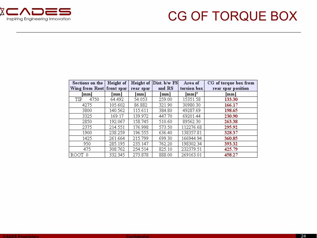
CG OF TORQUE BOX
25CADES Proprietary Confidential
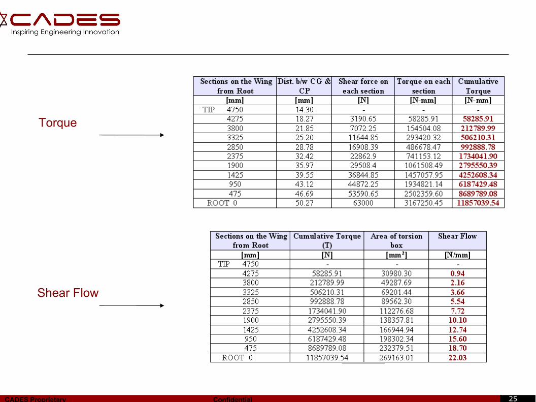
Torque
Shear Flow
26CADES Proprietary Confidential
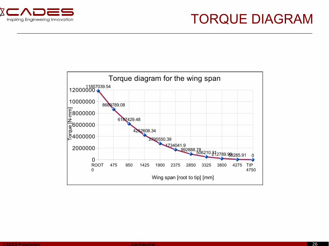
TORQUE DIAGRAM
ROOT 0
475 950 1425 1900 2375 2850 3325 3800 4275 TIP 4750
0
2000000
4000000
6000000
8000000
10000000
1200000011857039.54
8689789.08
6187429.48
4252608.34
2795550.391734041.9
992888.78506210.31212789.9958285.91 0
Torque diagram for the wing span
Wing span [root to tip] [mm]
Tor
que
[N- m
m]
27CADES Proprietary Confidential
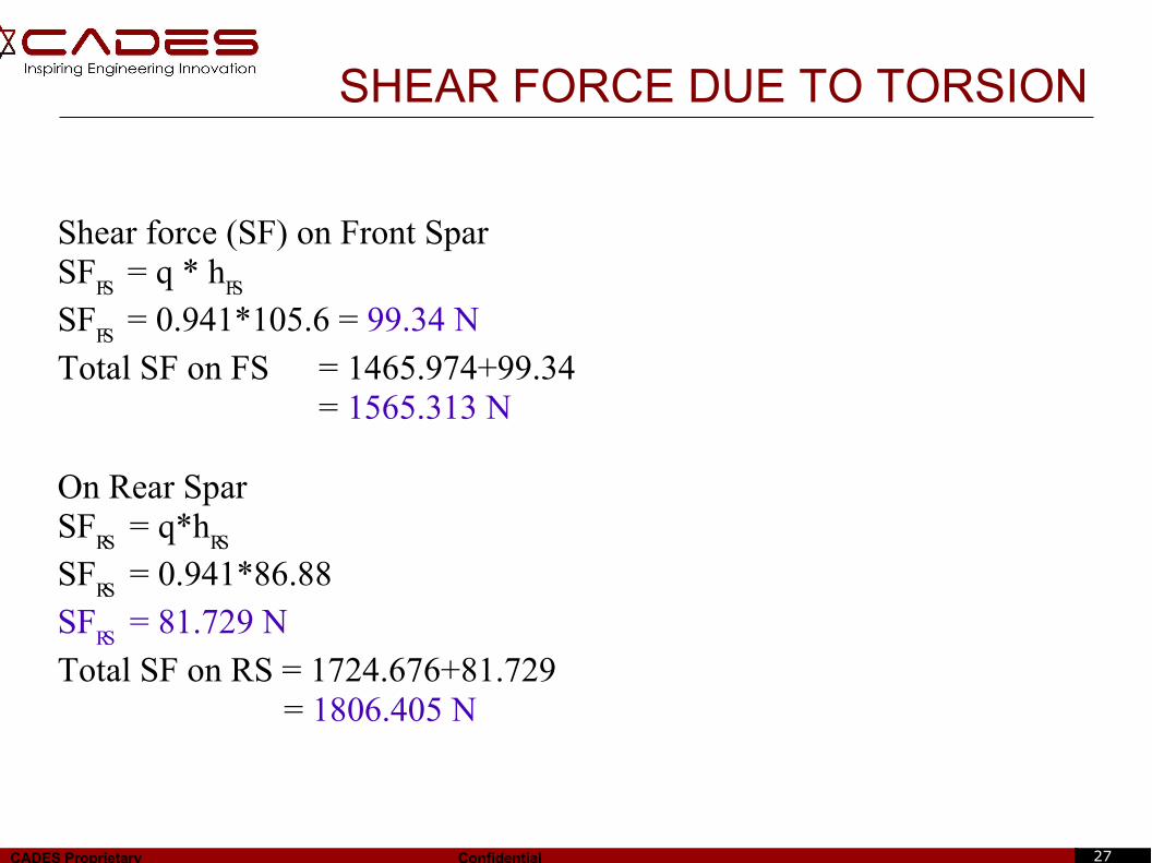
Shear force (SF) on Front SparSF
FS = q * h
FS
SFFS
= 0.941*105.6 = 99.34 N
Total SF on FS = 1465.974+99.34 = 1565.313 N
On Rear SparSF
RS = q*h
RS
SFRS
= 0.941*86.88SF
RS = 81.729 N
Total SF on RS = 1724.676+81.729 = 1806.405 N
SHEAR FORCE DUE TO TORSION
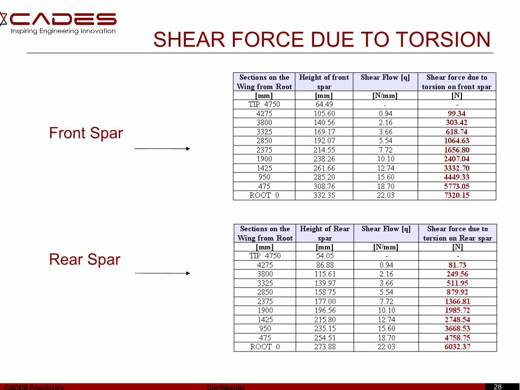
28CADES Proprietary Confidential
SHEAR FORCE DUE TO TORSION
Front Spar
Rear Spar
29CADES Proprietary Confidential
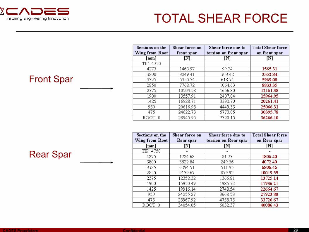
TOTAL SHEAR FORCE
Front Spar
Rear Spar
30CADES Proprietary Confidential
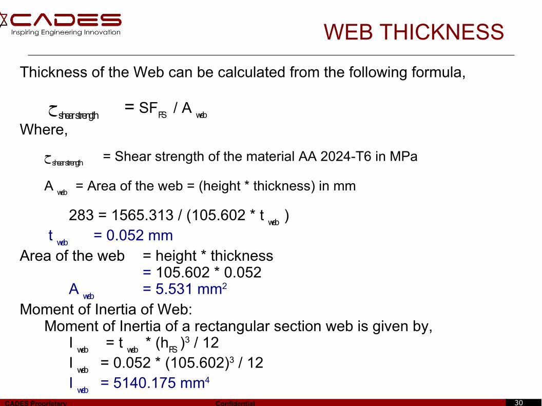
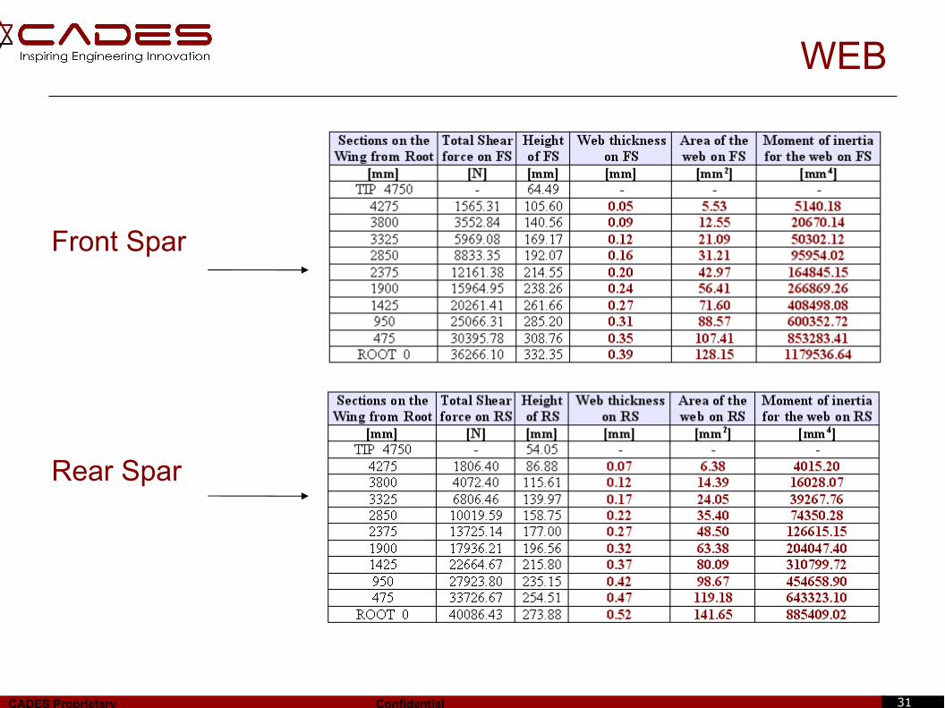
WEB THICKNESS
Thickness of the Web can be calculated from the following formula,
ح shear strength
= SFFS
/ A web
Where,
ح shear strength
= Shear strength of the material AA 2024-T6 in MPa
A web
= Area of the web = (height * thickness) in mm
283 = 1565.313 / (105.602 * t web
) t
web = 0.052 mmArea of the web = height * thickness
= 105.602 * 0.052 A
web = 5.531 mm2
Moment of Inertia of Web:Moment of Inertia of a rectangular section web is given by,
I web
= t web * (hFS
)3 / 12I
web = 0.052 * (105.602)3 / 12I
web = 5140.175 mm4
31CADES Proprietary Confidential
Front Spar
Rear Spar
WEB
32CADES Proprietary Confidential
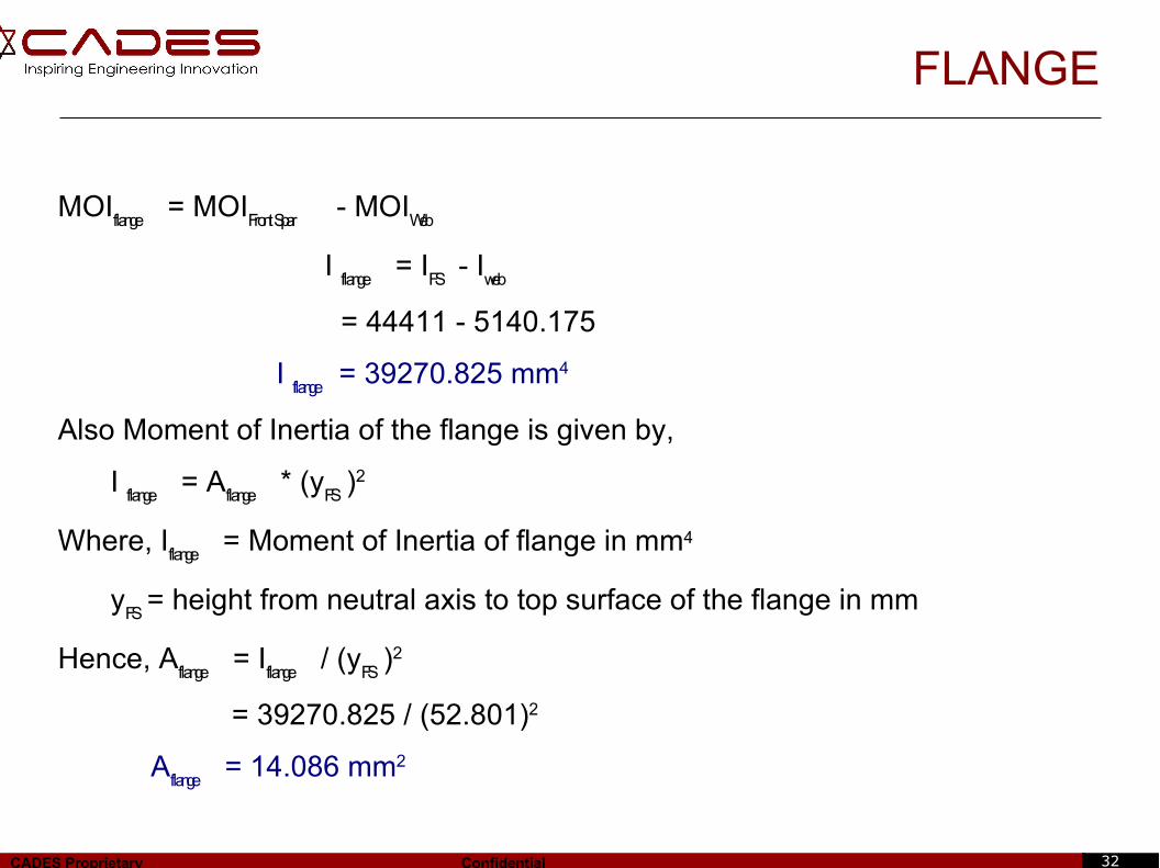
FLANGE
MOIflange
= MOIFront Spar
- MOIWeb
I flange
= IFS
- Iweb
= 44411 - 5140.175
I flange
= 39270.825 mm4
Also Moment of Inertia of the flange is given by,
I flange
= Aflange
* (yFS
)2
Where, Iflange
= Moment of Inertia of flange in mm4
yFS
= height from neutral axis to top surface of the flange in mm
Hence, Aflange
= Iflange
/ (yFS
)2
= 39270.825 / (52.801)2
Aflange
= 14.086 mm2
33CADES Proprietary Confidential
FLANGE
Front Spar
Rear Spar
34CADES Proprietary Confidential
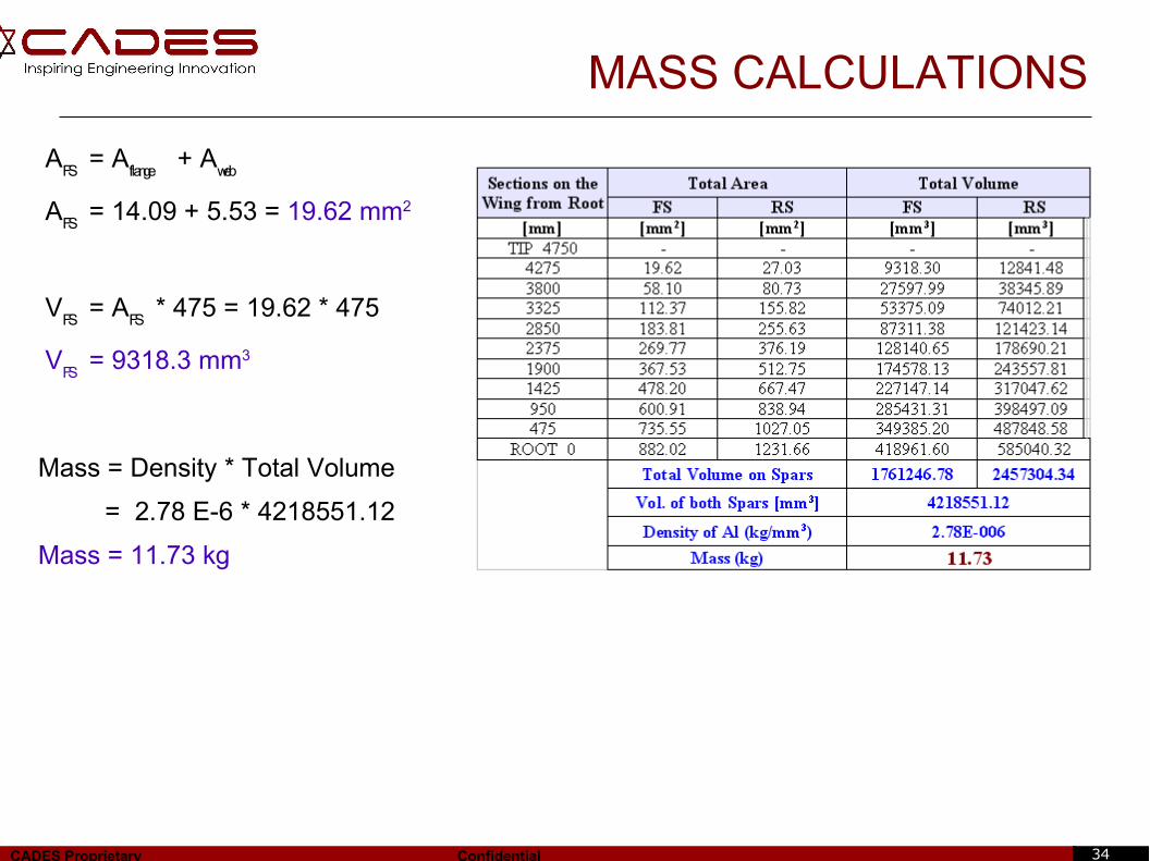
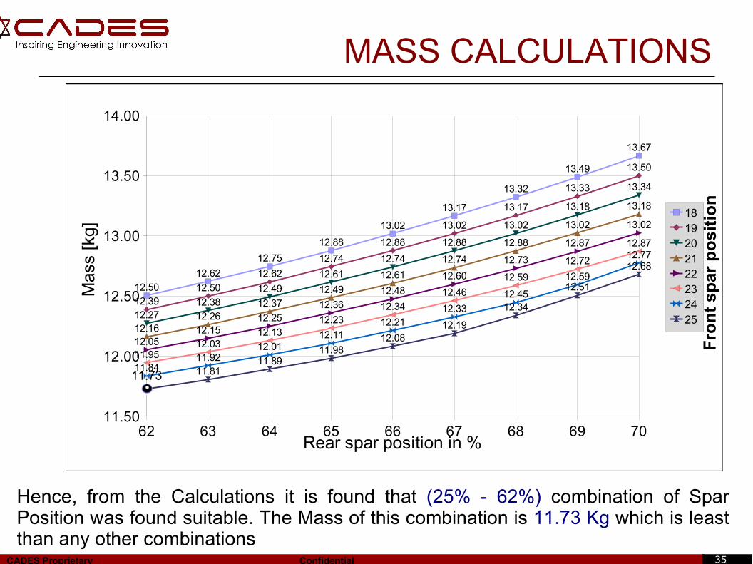
MASS CALCULATIONS
AFS
= Aflange
+ Aweb
AFS
= 14.09 + 5.53 = 19.62 mm2
VFS
= AFS
* 475 = 19.62 * 475
VFS
= 9318.3 mm3
Mass = Density * Total Volume
= 2.78 E-6 * 4218551.12
Mass = 11.73 kg
35CADES Proprietary Confidential
62 63 64 65 66 67 68 69 7011.50
12.00
12.50
13.00
13.50
14.00
12.50
12.62
12.75
12.88
13.02
13.17
13.32
13.49
13.67
12.3912.50
12.62
12.74
12.88
13.02
13.17
13.33
13.50
12.2712.38
12.49
12.61
12.74
12.88
13.02
13.18
13.34
12.1612.26
12.3712.49
12.61
12.74
12.88
13.02
13.18
12.0512.15
12.2512.36
12.48
12.60
12.73
12.87
13.02
11.9512.03
12.1312.23
12.34
12.46
12.59
12.72
12.87
11.8411.92
12.0112.11
12.2112.33
12.45
12.59
12.77
11.73 11.8111.89
11.9812.08
12.19
12.34
12.51
12.68
1819202122232425
Rear spar position in %
Mas
s [k
g]
MASS CALCULATIONS
Fro
nt
s par
po
siti
on
Hence, from the Calculations it is found that (25% - 62%) combination of Spar Position was found suitable. The Mass of this combination is 11.73 Kg which is least than any other combinations
36CADES Proprietary Confidential
BUCKLING
To Check whether the web fails under shear buckling.
Condition: Shear stressinduced
< Buckling stress (safe design)
●The thickness calculation is based on iterations,
Finduced
= q / tweb
Fcritical
= k*E*(tweb
/ b)2
where, q = shear flow, in N/mm
E = Young's Modulus, in MPa
b = height of spar, in mm
tweb
= web thickness, in mm
k = shear buckling coefficient from graph
[4]
[4]
37CADES Proprietary Confidential
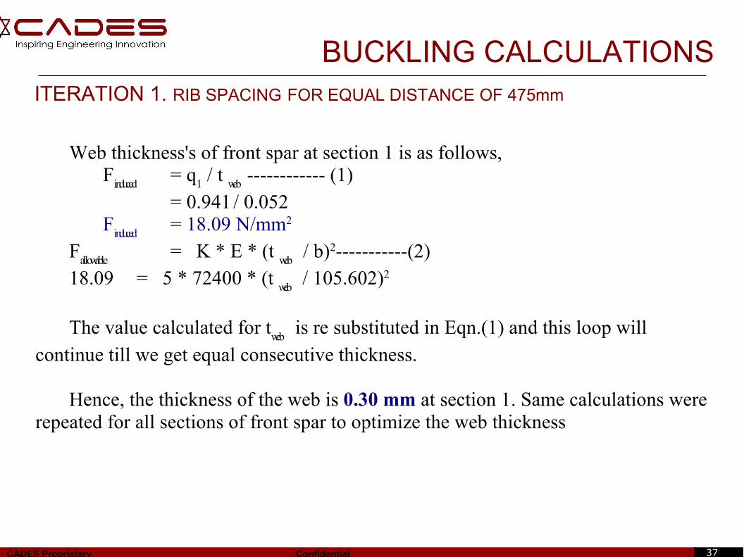
BUCKLING CALCULATIONSITERATION 1. RIB SPACING FOR EQUAL DISTANCE OF 475mm
Web thickness's of front spar at section 1 is as follows,F
induced = q
1 / t
web------------ (1)
= 0.941 / 0.052 F
induced = 18.09 N/mm2
Fallowable
= K * E * (t web
/ b)2-----------(2)18.09 = 5 * 72400 * (t
web / 105.602)2
The value calculated for tweb
is re substituted in Eqn.(1) and this loop will
continue till we get equal consecutive thickness.
Hence, the thickness of the web is 0.30 mm at section 1. Same calculations were repeated for all sections of front spar to optimize the web thickness
38CADES Proprietary Confidential
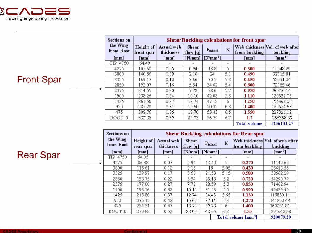
Front Spar
Rear Spar
39CADES Proprietary Confidential
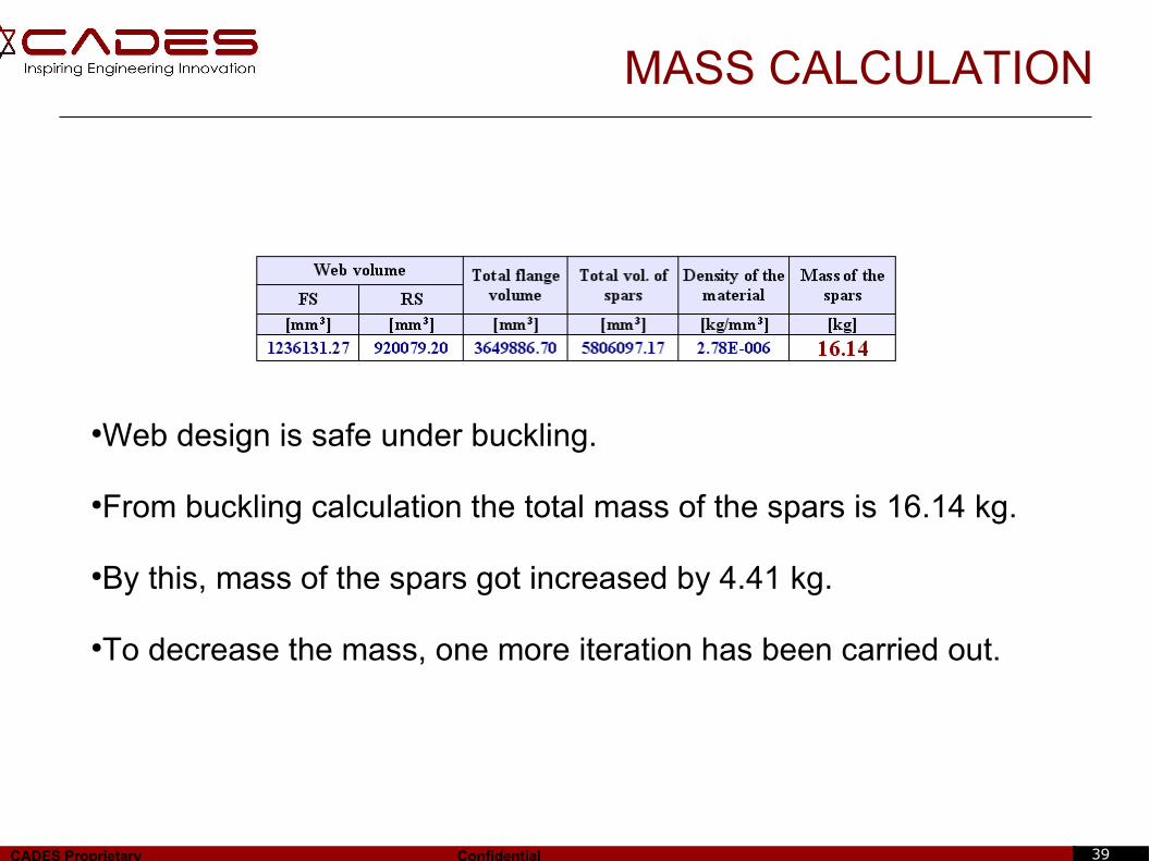
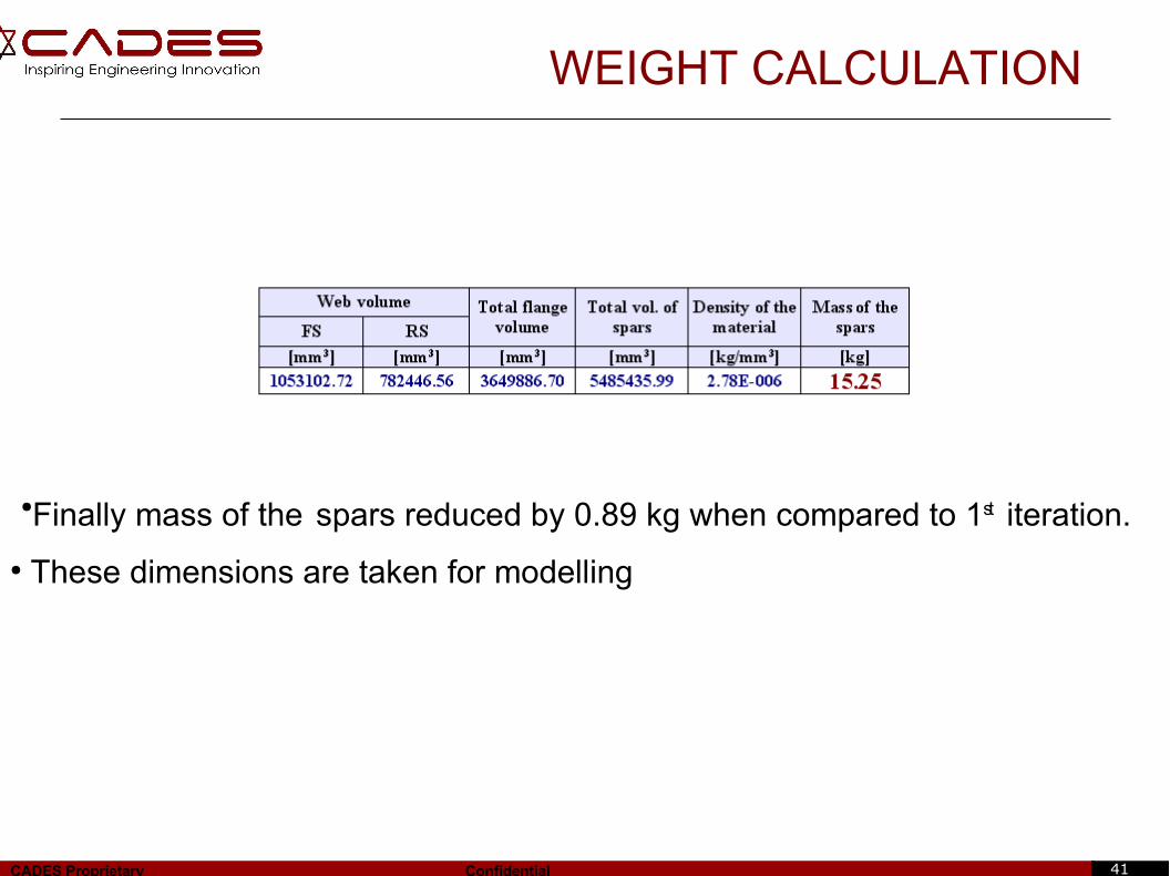
MASS CALCULATION
●Web design is safe under buckling.
●From buckling calculation the total mass of the spars is 16.14 kg.
●By this, mass of the spars got increased by 4.41 kg.
●To decrease the mass, one more iteration has been carried out.
40CADES Proprietary Confidential
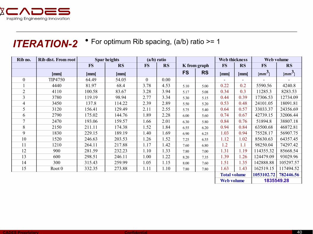
ITERATION-2● For optimum Rib spacing, (a/b) ratio >= 1
Rib no. Rib dist. From root Spar heights (a/b) ratioK from graph
Web thickness Web volumeFS RS FS RS FS RS FS RS
[mm] [mm] [mm] [mm] [mm]0 TIP4750 64.49 54.05 0 0.00 - - - -1 4440 81.97 68.4 3.78 4.53 5.10 5.00 0.22 0.2 5590.56 4240.82 4110 100.58 83.67 3.28 3.94 5.17 5.08 0.34 0.3 11285.3 8283.533 3780 119.19 98.94 2.77 3.34 5.30 5.15 0.44 0.39 17306.53 12734.094 3450 137.8 114.22 2.39 2.89 5.50 5.20 0.53 0.48 24101.05 18091.815 3120 156.41 129.49 2.11 2.55 5.75 5.40 0.64 0.57 33033.37 24356.696 2790 175.02 144.76 1.89 2.28 6.00 5.60 0.74 0.67 42739.15 32006.447 2470 193.06 159.57 1.66 2.01 6.30 5.80 0.84 0.76 51894.8 38807.188 2150 211.11 174.38 1.52 1.84 6.55 6.20 0.94 0.84 63500.68 46872.819 1830 229.15 189.19 1.40 1.69 6.90 6.25 1.03 0.94 75528.17 56907.7510 1520 246.63 203.53 1.26 1.52 7.25 6.55 1.12 1.02 85630.63 64357.4511 1210 264.11 217.88 1.17 1.42 7.60 6.80 1.2 1.1 98250.04 74297.4212 900 281.59 232.23 1.10 1.33 7.80 7.00 1.31 1.19 114355.32 85668.5413 600 298.51 246.11 1.00 1.22 8.20 7.35 1.39 1.26 124479.09 93029.9614 300 315.43 259.99 1.05 1.15 8.00 7.60 1.51 1.35 142888.88 105297.5715 Root 0 332.35 273.88 1.11 1.10 7.80 7.80 1.63 1.43 162519.15 117494.52
Total volume 1053102.72 782446.56Web volume 1835549.28
[mm3] [mm3]FS RS
41CADES Proprietary Confidential
WEIGHT CALCULATION
●Finally mass of the spars reduced by 0.89 kg when compared to 1st iteration.
● These dimensions are taken for modelling
42CADES Proprietary Confidential
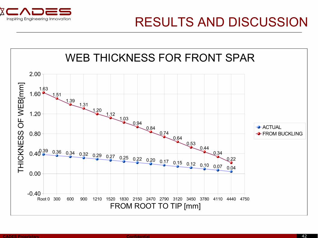
RESULTS AND DISCUSSION
Root 0 300 600 900 1210 1520 1830 2150 2470 2790 3120 3450 3780 4110 4440 4750-0.40
0.00
0.40
0.80
1.20
1.60
2.00
0.39 0.36 0.34 0.32 0.29 0.27 0.25 0.22 0.20 0.17 0.15 0.12 0.10 0.07 0.04
1.631.51
1.391.31
1.201.12
1.030.94
0.840.74
0.640.53
0.440.34
0.22
WEB THICKNESS FOR FRONT SPAR
ACTUALFROM BUCKLING
FROM ROOT TO TIP [mm]
TH
ICK
NE
SS
OF
WE
B[m
m]
43CADES Proprietary Confidential
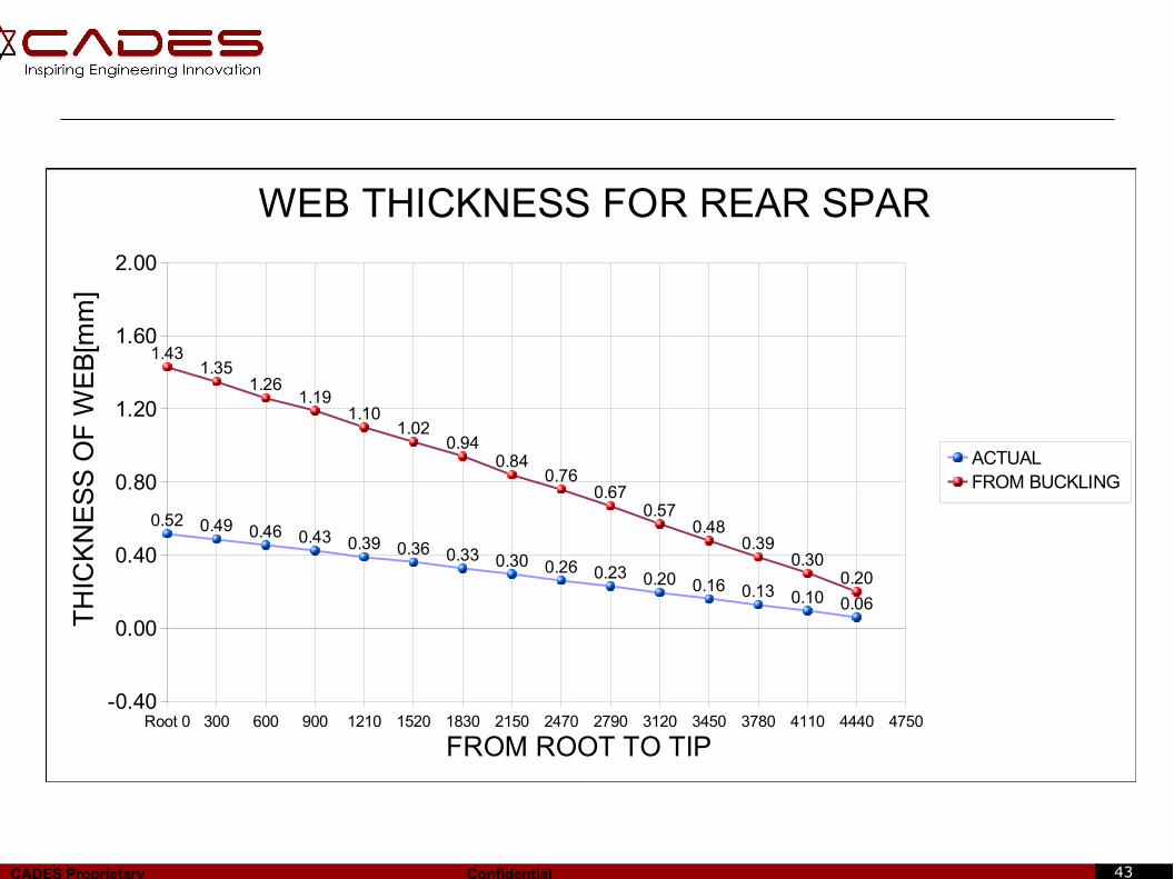
Root 0 300 600 900 1210 1520 1830 2150 2470 2790 3120 3450 3780 4110 4440 4750-0.40
0.00
0.40
0.80
1.20
1.60
2.00
0.52 0.49 0.46 0.43 0.39 0.36 0.33 0.30 0.26 0.23 0.20 0.16 0.13 0.10 0.06
1.431.35
1.261.19
1.101.02
0.940.84
0.760.67
0.570.48
0.390.30
0.20
WEB THICKNESS FOR REAR SPAR
ACTUALFROM BUCKLING
FROM ROOT TO TIP
TH
ICK
NE
SS
OF
WE
B[m
m]
44CADES Proprietary Confidential
CONCLUSION
● Front Spar positioning is estimated to 25% and Rear Spar to 62% of the
Chord Length.
● Flange and web dimensions are calculated and suitable changes in
dimensions are incorporated from manufacturing point of view.
● Number of Ribs and their positioning for the prevention of bending and
buckling of Spars is calculated.
● Mass of the spars calculated from iterations is 15.25 kg.
● The Detail drawings for the front and rear spars are provided using CATIA V5.
45CADES Proprietary Confidential
SCOPE FOR FURTHER WORK
● Spar position can be optimized based on buckling calculations.
● Further optimization of Rib is possible.--Varying number of Ribs and spacing of Ribs.
● Use of other materials for the design of spars can be thought of.
● Detail stress analysis of individual components and its validation with calculations can be carried out.
46CADES Proprietary Confidential
CAD
47CADES Proprietary Confidential
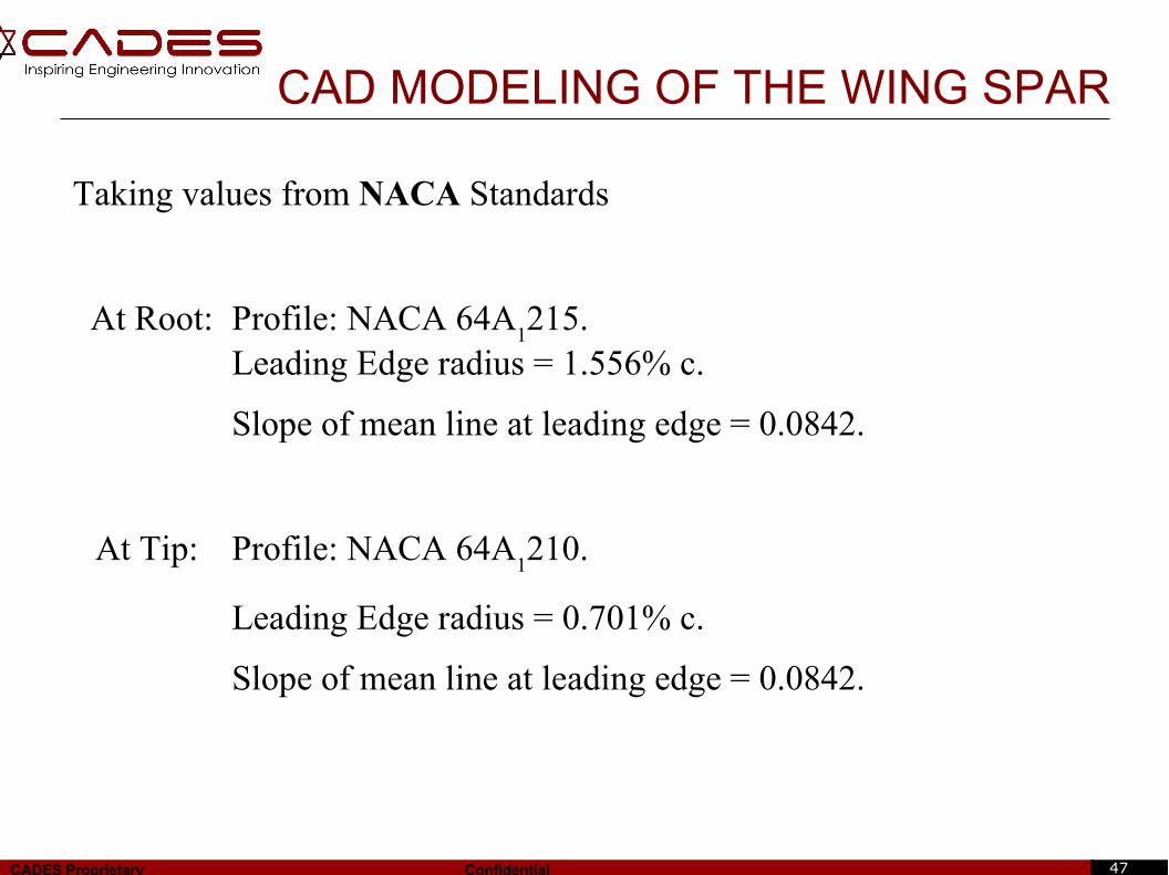
Taking values from NACA Standards
At Root: Profile: NACA 64A1215.
Leading Edge radius = 1.556% c.
Slope of mean line at leading edge = 0.0842.
At Tip: Profile: NACA 64A1210.
Leading Edge radius = 0.701% c.
Slope of mean line at leading edge = 0.0842.
CAD MODELING OF THE WING SPAR
48CADES Proprietary Confidential
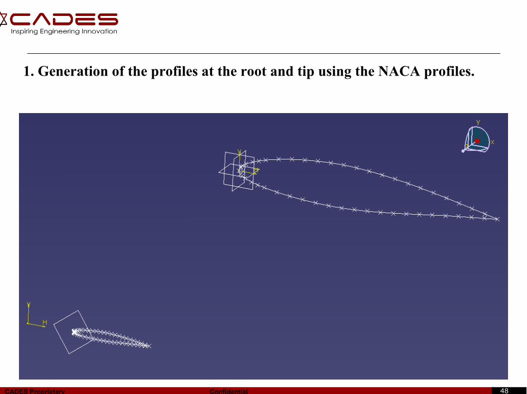
1. Generation of the profiles at the root and tip using the NACA profiles.
49CADES Proprietary Confidential
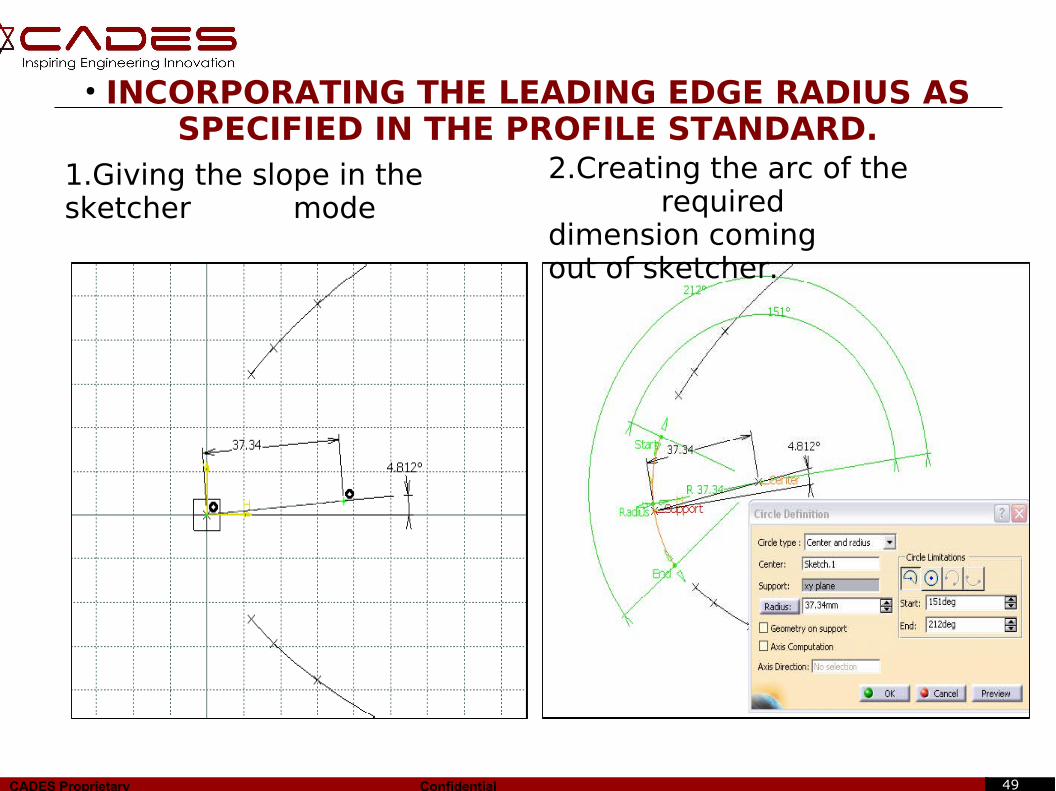
● INCORPORATING THE LEADING EDGE RADIUS AS SPECIFIED IN THE PROFILE STANDARD.
1.Giving the slope in the sketcher mode
2.Creating the arc of the required dimension coming out of sketcher.

50CADES Proprietary Confidential
● Using the connect curve option to join the leading edge radius and the aerofoil profile.
● Create the surface using multi section surface option.
51CADES Proprietary Confidential
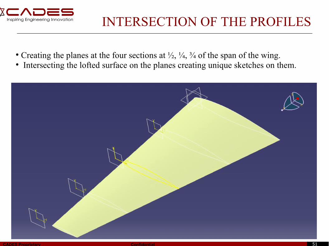
INTERSECTION OF THE PROFILES
● Creating the planes at the four sections at ½, ¼, ¾ of the span of the wing.● Intersecting the lofted surface on the planes creating unique sketches on them.
52CADES Proprietary Confidential
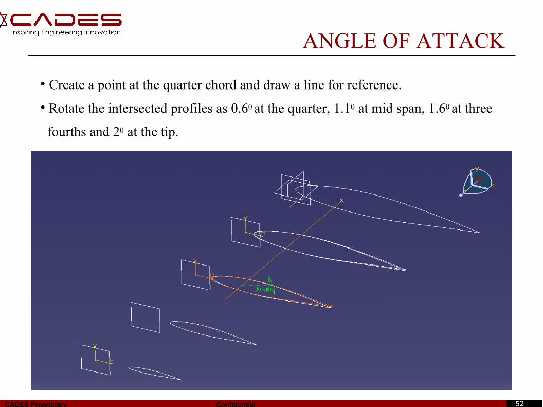
ANGLE OF ATTACK
● Create a point at the quarter chord and draw a line for reference.
● Rotate the intersected profiles as 0.60 at the quarter, 1.10 at mid span, 1.60 at three
fourths and 20 at the tip.
53CADES Proprietary Confidential
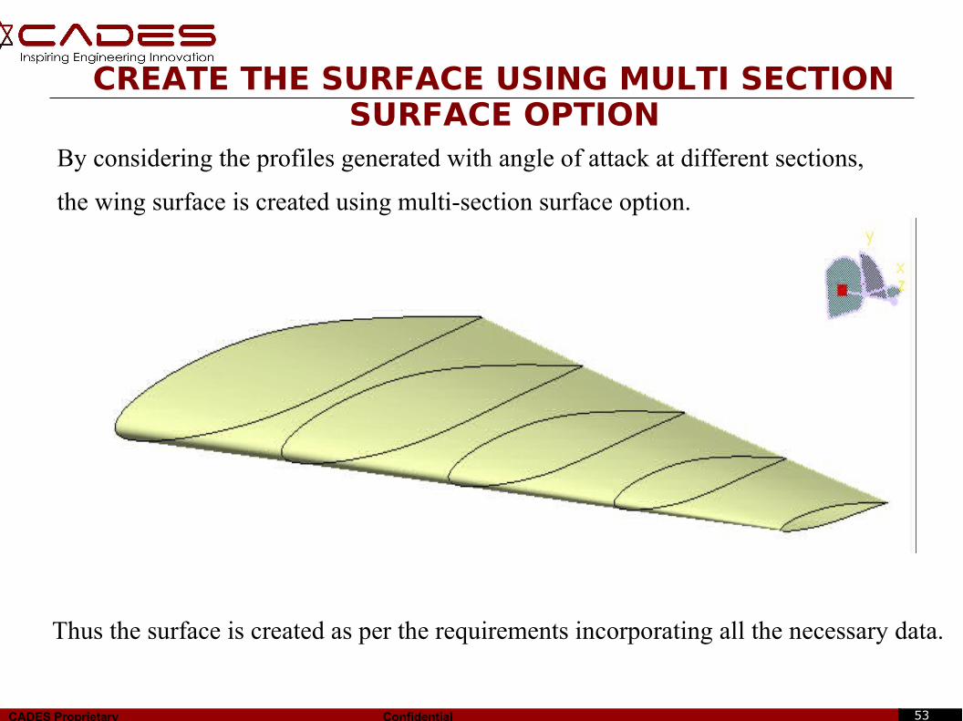
By considering the profiles generated with angle of attack at different sections,
the wing surface is created using multi-section surface option.
CREATE THE SURFACE USING MULTI SECTION SURFACE OPTION
Thus the surface is created as per the requirements incorporating all the necessary data.
54CADES Proprietary Confidential
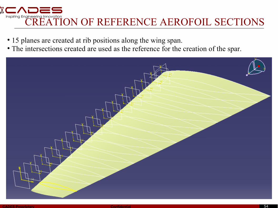
CREATION OF REFERENCE AEROFOIL SECTIONS
● 15 planes are created at rib positions along the wing span.● The intersections created are used as the reference for the creation of the spar.
55CADES Proprietary Confidential
CONSIDERATIONS MADE DURING THE DESIGN OF SPAR
ELEMENTS
●The maintenance of the nose box is made easy.
● The front spar is I – section.
● The rear spar is C – section.
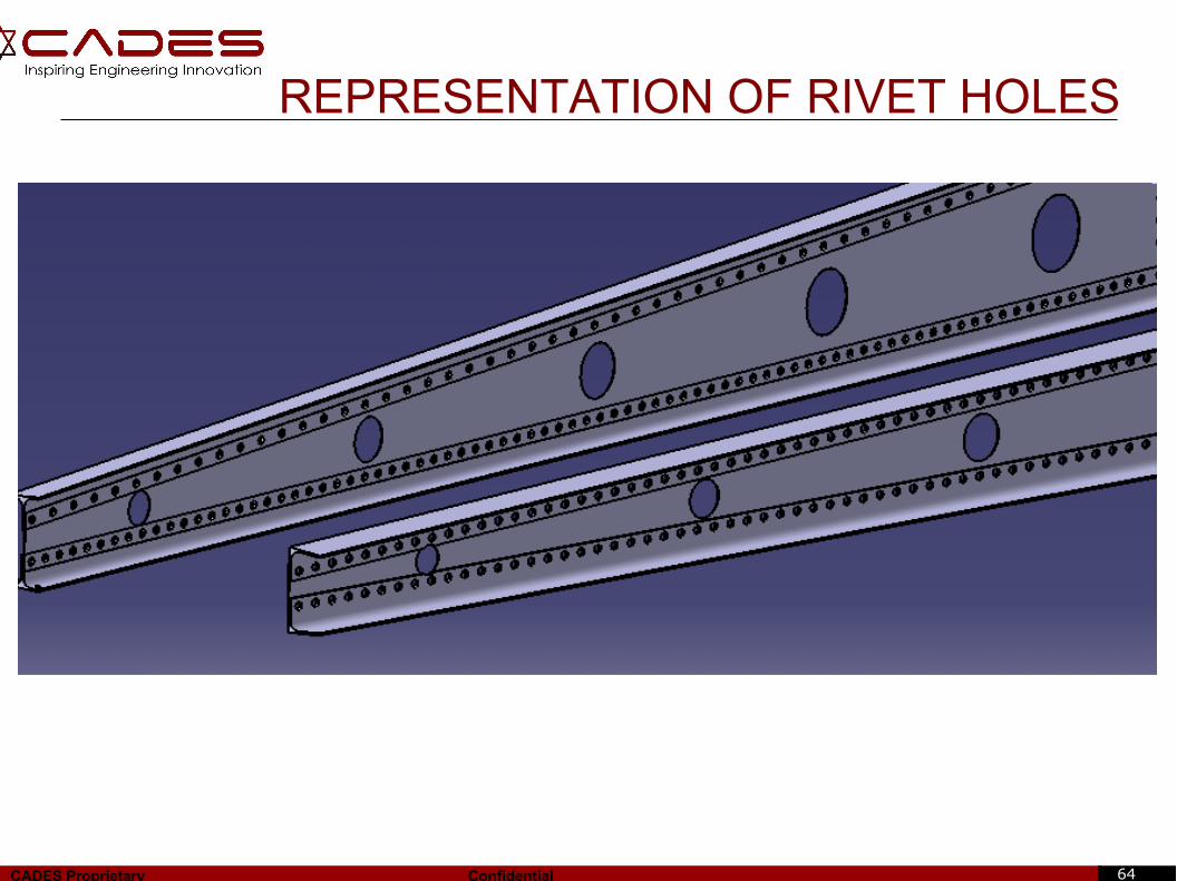
● Minimum distance required for a single row riveting is kept as 15 mm.
56CADES Proprietary Confidential
DESIGNING OF SPAR ON MANUFACTURING BASIS
➢ The front spar is placed at 25% of chord length from leading edge.
➢ The rear spar is placed at 62% of chord length from leading edge.
➢ Thicknesses of the flanges and webs are different.
➢ The flanges are made of T-sections and L- sections.
➢ The webs are made with sheet metal.
➢ The thicknesses are optimized based on the availability of the standard gages of sheet metal.
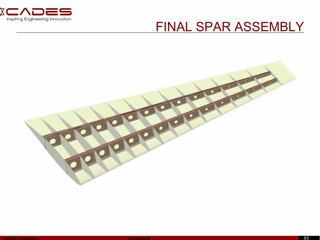
➢ The final assembly of elements can be fastened with rivets.
57CADES Proprietary Confidential
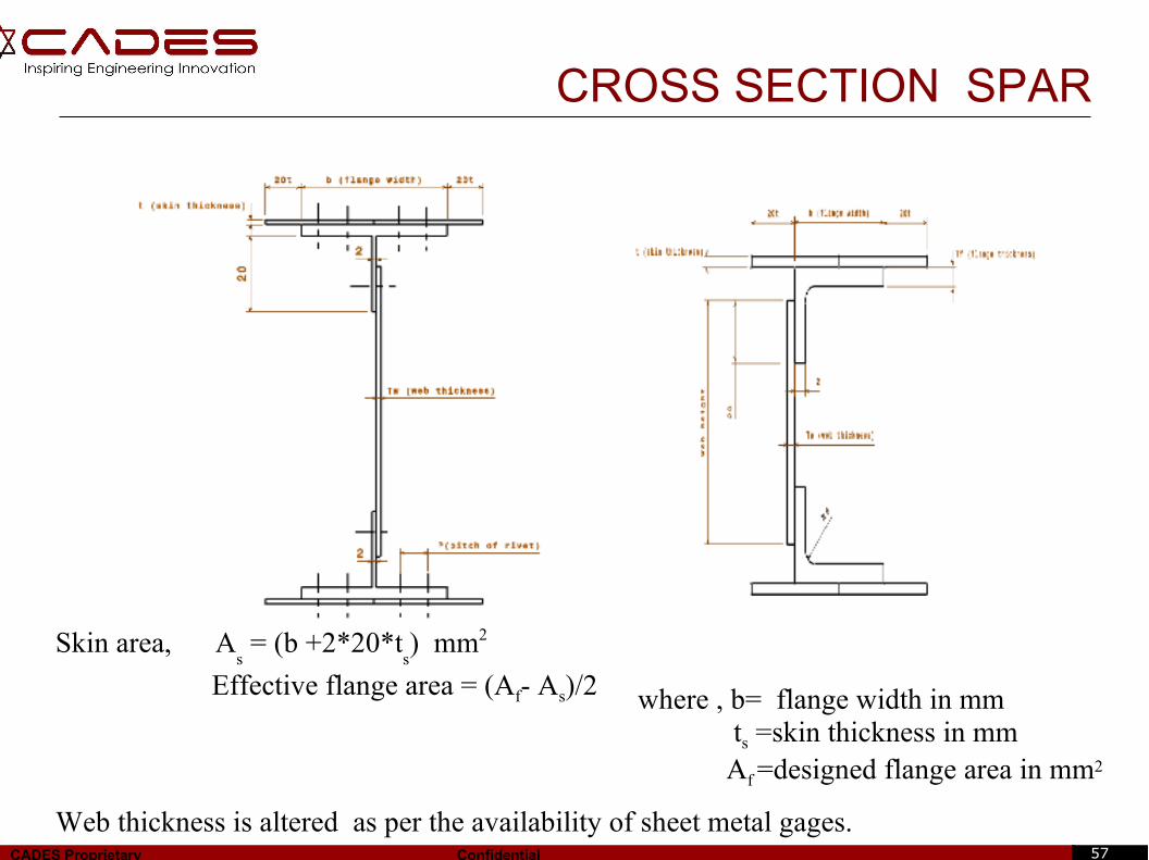
CROSS SECTION SPAR
Skin area, As = (b +2*20*t
s) mm2
Effective flange area = (Af- As)/2
Web thickness is altered as per the availability of sheet metal gages.
where , b= flange width in mm ts =skin thickness in mm Af =designed flange area in mm2
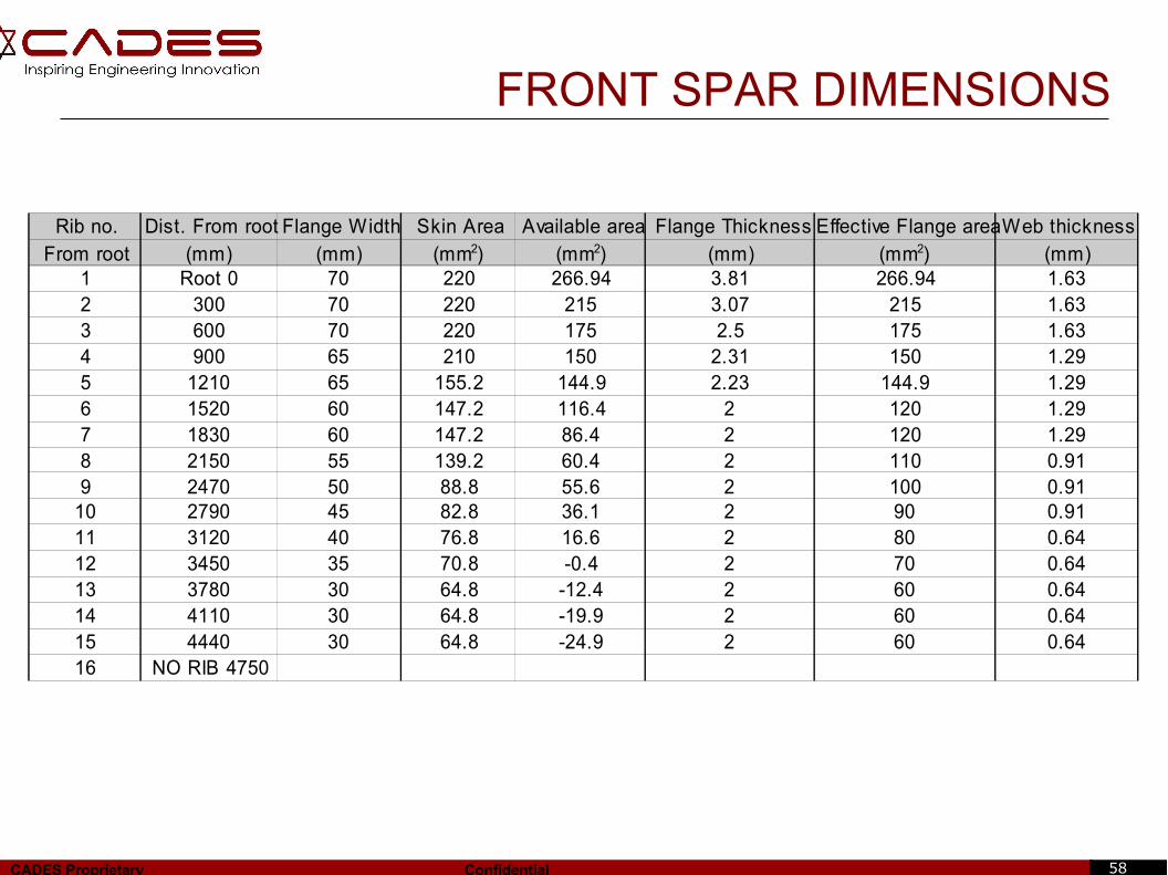
58CADES Proprietary Confidential
Rib no. Dist. From root Flange Width Skin Area Available area Flange Thickness Effective Flange areaWeb thicknessFrom root (mm) (mm) (mm) (mm)
1 Root 0 70 220 266.94 3.81 266.94 1.632 300 70 220 215 3.07 215 1.633 600 70 220 175 2.5 175 1.634 900 65 210 150 2.31 150 1.295 1210 65 155.2 144.9 2.23 144.9 1.296 1520 60 147.2 116.4 2 120 1.297 1830 60 147.2 86.4 2 120 1.298 2150 55 139.2 60.4 2 110 0.919 2470 50 88.8 55.6 2 100 0.91
10 2790 45 82.8 36.1 2 90 0.9111 3120 40 76.8 16.6 2 80 0.6412 3450 35 70.8 -0.4 2 70 0.6413 3780 30 64.8 -12.4 2 60 0.6414 4110 30 64.8 -19.9 2 60 0.6415 4440 30 64.8 -24.9 2 60 0.6416 NO RIB 4750
(mm2) (mm2) (mm2)
FRONT SPAR DIMENSIONS
59CADES Proprietary Confidential
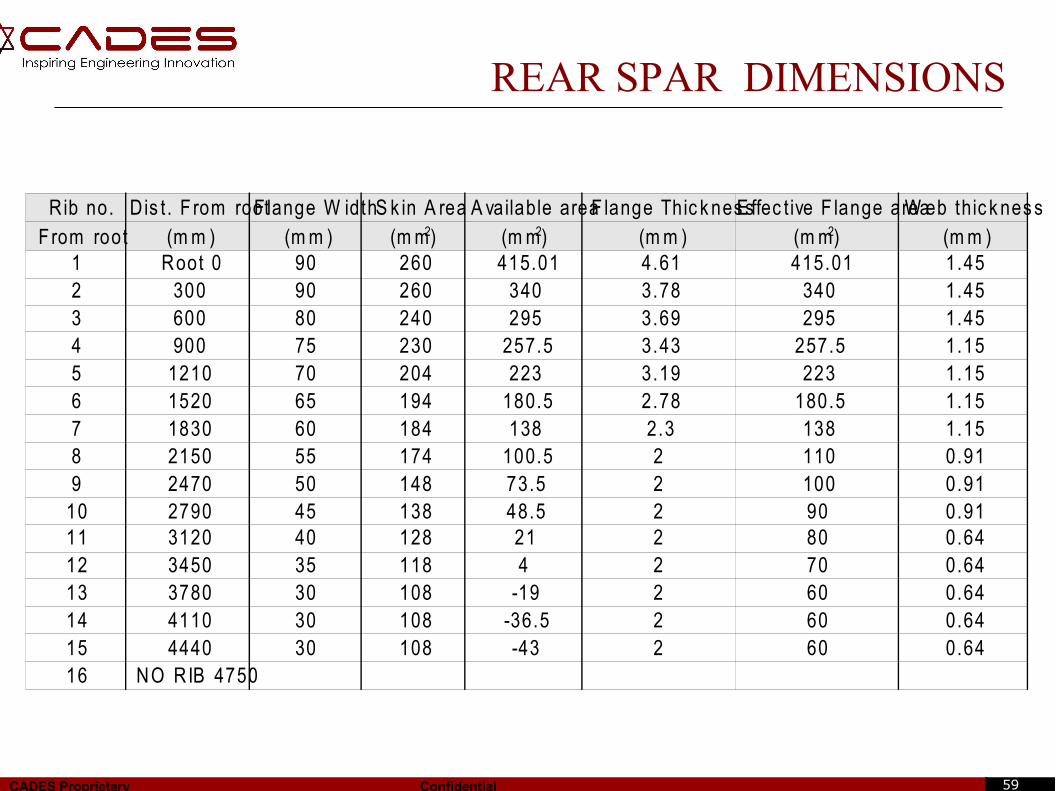
REAR SPAR DIMENSIONS
Rib no. D is t . F rom rootF lange W idthS k in A rea A vailable areaF lange Thic k nes sE ffec t ive F lange areaW eb thic k nes sF rom root (m m ) (m m ) (m m ) (m m )
1 Root 0 90 260 415.01 4.61 415.01 1.452 300 90 260 340 3.78 340 1.453 600 80 240 295 3.69 295 1.454 900 75 230 257.5 3.43 257.5 1.155 1210 70 204 223 3.19 223 1.156 1520 65 194 180.5 2.78 180.5 1.157 1830 60 184 138 2.3 138 1.158 2150 55 174 100.5 2 110 0.919 2470 50 148 73.5 2 100 0.91
10 2790 45 138 48.5 2 90 0.9111 3120 40 128 21 2 80 0.6412 3450 35 118 4 2 70 0.6413 3780 30 108 -19 2 60 0.6414 4110 30 108 -36.5 2 60 0.6415 4440 30 108 -43 2 60 0.6416 NO RIB 4750
(m m2) (m m2) (m m2)
60CADES Proprietary Confidential
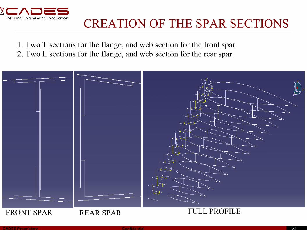
CREATION OF THE SPAR SECTIONS
1. Two T sections for the flange, and web section for the front spar.2. Two L sections for the flange, and web section for the rear spar.
FRONT SPAR REAR SPAR FULL PROFILE
61CADES Proprietary Confidential
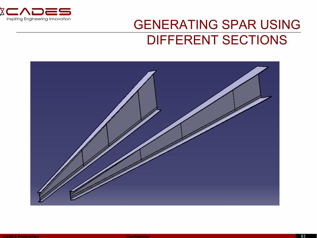
GENERATING SPAR USINGDIFFERENT SECTIONS
62CADES Proprietary Confidential
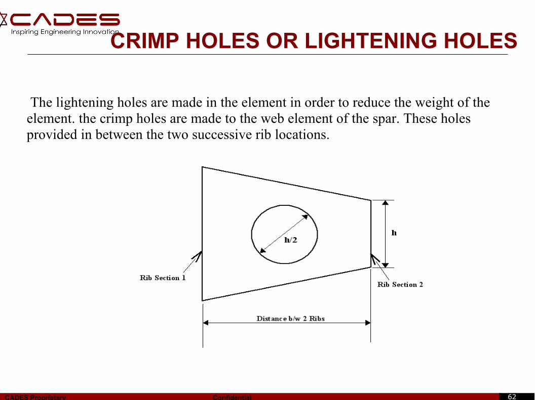
CRIMP HOLES OR LIGHTENING HOLES
The lightening holes are made in the element in order to reduce the weight of the element. the crimp holes are made to the web element of the spar. These holes provided in between the two successive rib locations.
63CADES Proprietary Confidential
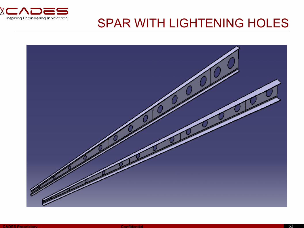
SPAR WITH LIGHTENING HOLES
64CADES Proprietary Confidential
REPRESENTATION OF RIVET HOLES
65CADES Proprietary Confidential
FINAL SPAR ASSEMBLY
66CADES Proprietary Confidential
BIBLIOGRAPHY
1] Abbot & Albert,'Theory of wing sections',Dover publication,1949.
2] David J. Perry,'Aircraft structures',Mc-Graw Hill publication,1950.
3] E. F. Bruhn,'Analysis and design of flight vehicle structures',1973.
4] Michael C. Y. Niu, 'Airframe Stress Analysis and Sizing', 2001.
5] Michael C. Y. Niu, 'Airframe structural design', Conmilit press Ltd., 1989.
6] Kuethe and Schetzer, 'Foundations of Aerodynamics', 2nd Edition, John Wiley
and Sons, New York, 1959.
7] ASM Material Data Sheet
8] MIL Handbook.
&CADES Library.

67CADES Proprietary Confidential
THANK YOU
CADES Digitech Pvt. Ltd.Tel: +91 80 4193 9000Fax: +91 80 4193 9099
URL: www.cadestech.com