Embed Size (px)
Citation preview

Operating manual
HDM 50 pro, HDM 80 pro Item-no.: 110600330, 110600340, 110600350, 110600430, 110600440, 110600450
Tran
slat
ion o
f th
e
ori
ginal
oper
atin
g m
anual
Fig. 110600350
2 44 1689 001 GB-F HDM 50 pro, HDM 80 pro
Important! The operating manual is always to be read before commissioning the equipment. No warranty claim will be granted for faults and damage to the equipment arising from insufficient knowledge of the operating manual.
Copyright © HORN GmbH & Co. KG. All rights reserved. Text, graphics and layout copyright protected. Reproduction and copying, including in part, only permitted with written permission. Technical changes reserved.
Service Hotline +49 1805 900 301 (0,14 €/Min: on the German landline network, Mobile telephone max. 0,42 €/Min.) [email protected]
Document-No.: 44 1689 001 GB-F Translation of document-no. 44 1689 001 DE-F As of: 19.08.2015
44 1689 001 GB-F HDM 50 pro, HDM 80 pro 3
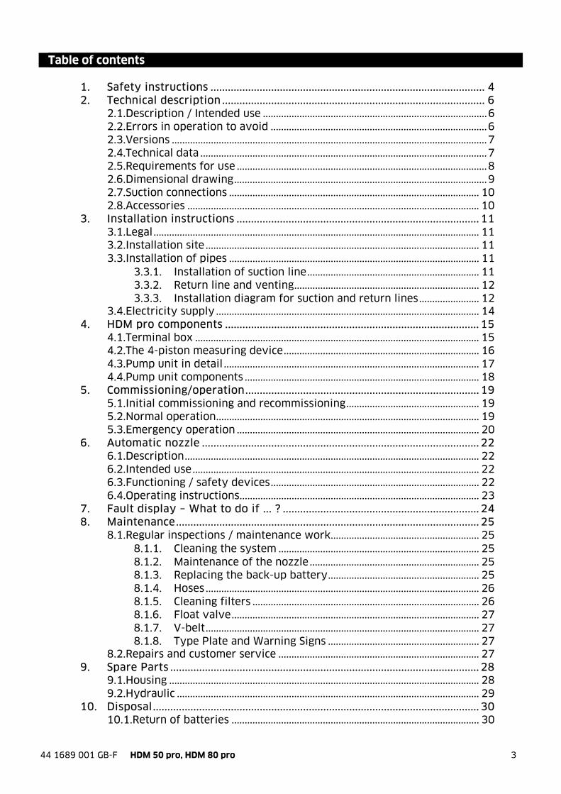
Table of contents 1. Safety instructions ............................................................................................... 4 2. Technical description ........................................................................................... 6
2.1.Description / Intended use ...................................................................................... 6 2.2.Errors in operation to avoid ................................................................................... 6 2.3.Versions ......................................................................................................................... 7 2.4.Technical data .............................................................................................................. 7 2.5.Requirements for use ................................................................................................ 8 2.6.Dimensional drawing ................................................................................................. 9 2.7.Suction connections ................................................................................................ 10 2.8.Accessories ................................................................................................................ 10
3. Installation instructions .................................................................................... 11 3.1.Legal ............................................................................................................................. 11 3.2.Installation site ......................................................................................................... 11 3.3.Installation of pipes ................................................................................................ 11
3.3.1. Installation of suction line .................................................................. 11 3.3.2. Return line and venting ....................................................................... 12 3.3.3. Installation diagram for suction and return lines ....................... 12
3.4.Electricity supply ..................................................................................................... 14 4. HDM pro components ........................................................................................ 15
4.1.Terminal box ............................................................................................................. 15 4.2.The 4-piston measuring device ........................................................................... 16 4.3.Pump unit in detail .................................................................................................. 17 4.4.Pump unit components .......................................................................................... 18
5. Commissioning/operation ................................................................................. 19 5.1.Initial commissioning and recommissioning ................................................... 19 5.2.Normal operation ..................................................................................................... 19 5.3.Emergency operation ............................................................................................. 20
6. Automatic nozzle ................................................................................................ 22 6.1.Description ................................................................................................................. 22 6.2.Intended use .............................................................................................................. 22 6.3.Functioning / safety devices ................................................................................ 22 6.4.Operating instructions ............................................................................................ 23
7. Fault display – What to do if ... ? .................................................................... 24 8. Maintenance ......................................................................................................... 25
8.1.Regular inspections / maintenance work ......................................................... 25 8.1.1. Cleaning the system ............................................................................. 25 8.1.2. Maintenance of the nozzle ................................................................. 25 8.1.3. Replacing the back-up battery .......................................................... 25 8.1.4. Hoses ......................................................................................................... 26 8.1.5. Cleaning filters ....................................................................................... 26 8.1.6. Float valve ............................................................................................... 27 8.1.7. V-belt ......................................................................................................... 27 8.1.8. Type Plate and Warning Signs .......................................................... 27
8.2.Repairs and customer service ............................................................................. 27 9. Spare Parts ........................................................................................................... 28
9.1.Housing ....................................................................................................................... 28 9.2.Hydraulic .................................................................................................................... 29
10. Disposal ................................................................................................................. 30 10.1.Return of batteries ............................................................................................... 30

4 44 1689 001 GB-F HDM 50 pro, HDM 80 pro
1. Safety instructions
The device is a state of the art piece of equipment and has been constructed according to recognised safety specifications. It is nevertheless possible that use of the device will present hazards to the operator or to third parties, or may damage the device or other property. It is therefore essential to act in accordance with these safety instructions, and in particular with those sections identified as warnings.
Warning notices and symbols
In the operating manual, the following signs are used for highlighting important information.
Special information for economical use of the equipment.
Special information or "dos and don'ts" for damage prevention.
Information or “dos and don'ts” for the prevention of damage to persons or equipment.
Appropriate use
The device may only be used if it is in perfect condition, and then only for its intended purpose, in compliance with all safety regulations, with an awareness of the potential risks, and according to the operating manual. Any faults that may impair the safety must be rectified immediately. The device and its components are only to be used for handling the liquids listed and the purpose described. Using the machine for any other purpose would constitute inappropriate use. The manufacturer is not responsible for any loss arising as a result of this, the risk for this is borne only by the operating company.
Organisational measures
This operating manual should always be kept readily available at the site of operation! Each person concerned with the assembly, commissioning, maintenance and operation of the equipment must have read and understood the entire operating manual. It is essential that the type plate and the warning notices attached to the device are observed, and are maintained in a fully readable condition.
Qualified personnel
The operating, maintenance and assembly personnel must be appropriately qualified for their work. The areas of responsibility, competences and supervision of the personnel must be precisely regulated by the operating company. If the personnel do not have the required knowledge, they must be trained and instructed. The operating company must also ensure that the contents of the operating manual are properly understood by the personnel.
Waters protection
The device has been designed to handle water hazardous substances. The regulations on the operating place (e.g. Water Resources Act WHG, = ordinance on installations for handling of substances hazardous to water VAwS) must be adhered to.

44 1689 001 GB-F HDM 50 pro, HDM 80 pro 5
Hydraulics
Only persons with special knowledge and experience with hydraulic systems may carry out work on hydraulic parts and equipment. All lines, hoses and screw joints should regularly be checked for leaks and visible external damage. Any damage must be rectified immediately. Any oil spurting out can cause injuries and fire. The relevant safety regulations for the product must be followed when handling oils, greases or other chemical substances!
Maintenance and Service
According to the regulations of the water resources law only authorized services may work on devices for flammable and/or water endangering substances. During such works, appropriate tools are to be used (avoid sparking). Before any kind of work on the device, all fuel lines are to be completely emptied and aerated. Do not make any changes. Modifications or additions to the device which may affect the safety cannot be carried out without consent of the manufacturer. Exclusively genuine spare parts made by the manufacturer may be used.
Electric power
Work on the electrical equipment may only be carried out by a qualified electrician or by trained persons under the guidance and supervision of a qualified electrician according to electro-technical guidelines.Machine or system components, on which inspection, maintenance or repair work is to be carried out must be de-energised.
6 44 1689 001 GB-F HDM 50 pro, HDM 80 pro
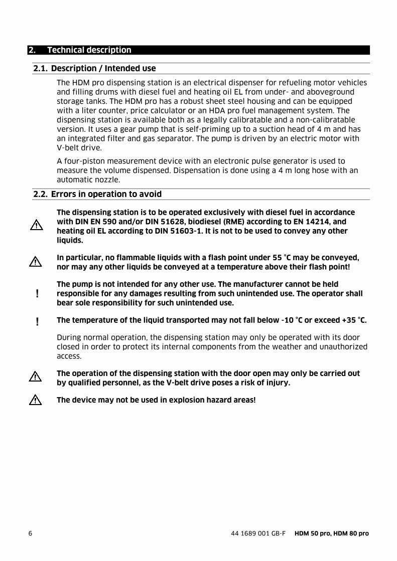
2. Technical description
2.1. Description / Intended use
The HDM pro dispensing station is an electrical dispenser for refueling motor vehicles and filling drums with diesel fuel and heating oil EL from under- and aboveground storage tanks. The HDM pro has a robust sheet steel housing and can be equipped with a liter counter, price calculator or an HDA pro fuel management system. The dispensing station is available both as a legally calibratable and a non-calibratable version. It uses a gear pump that is self-priming up to a suction head of 4 m and has an integrated filter and gas separator. The pump is driven by an electric motor with V-belt drive.
A four-piston measurement device with an electronic pulse generator is used to measure the volume dispensed. Dispensation is done using a 4 m long hose with an automatic nozzle.
2.2. Errors in operation to avoid
The dispensing station is to be operated exclusively with diesel fuel in accordance with DIN EN 590 and/or DIN 51628, biodiesel (RME) according to EN 14214, and heating oil EL according to DIN 51603-1. It is not to be used to convey any other liquids.
In particular, no flammable liquids with a flash point under 55 °C may be conveyed, nor may any other liquids be conveyed at a temperature above their flash point!
The pump is not intended for any other use. The manufacturer cannot be held responsible for any damages resulting from such unintended use. The operator shall bear sole responsibility for such unintended use.
The temperature of the liquid transported may not fall below -10 °C or exceed +35 °C.
During normal operation, the dispensing station may only be operated with its door closed in order to protect its internal components from the weather and unauthorized access.
The operation of the dispensing station with the door open may only be carried out by qualified personnel, as the V-belt drive poses a risk of injury.
The device may not be used in explosion hazard areas!
44 1689 001 GB-F HDM 50 pro, HDM 80 pro 7
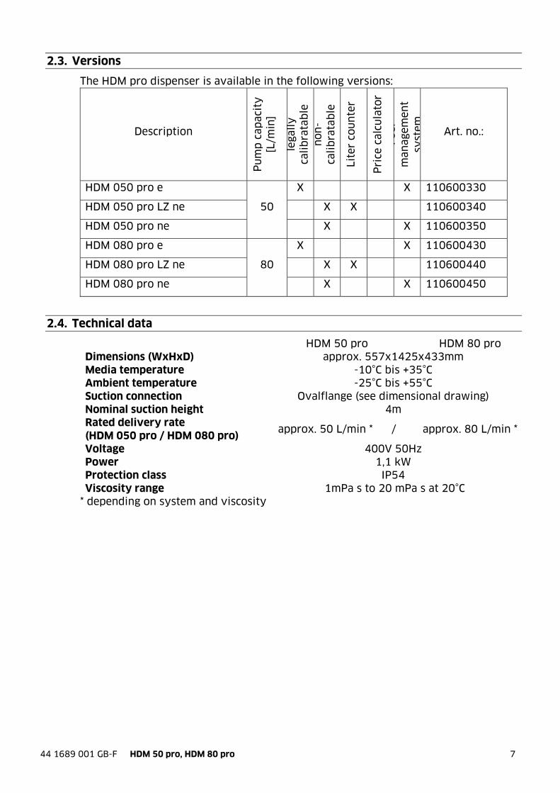
2.3. Versions
The HDM pro dispenser is available in the following versions:
Description
Pu
mp
cap
acit
y
[L/m
in]
lega
lly
ca
lib
rata
ble
n
on
-ca
lib
rata
ble
Lite
r co
un
ter
Pri
ce c
alcu
lato
r Fu
el
man
agem
ent
syst
em Art. no.:
HDM 050 pro e
50
X X 110600330
HDM 050 pro LZ ne X X 110600340
HDM 050 pro ne X X 110600350
HDM 080 pro e
80
X X 110600430
HDM 080 pro LZ ne X X 110600440
HDM 080 pro ne X X 110600450
2.4. Technical data
HDM 50 pro HDM 80 pro Dimensions (WxHxD) approx. 557x1425x433mm Media temperature -10°C bis +35°C Ambient temperature -25°C bis +55°C Suction connection Ovalflange (see dimensional drawing) Nominal suction height 4m Rated delivery rate (HDM 050 pro / HDM 080 pro)
approx. 50 L/min * / approx. 80 L/min *
Voltage 400V 50Hz Power 1,1 kW Protection class IP54 Viscosity range 1mPa s to 20 mPa s at 20°C
* depending on system and viscosity
8 44 1689 001 GB-F HDM 50 pro, HDM 80 pro
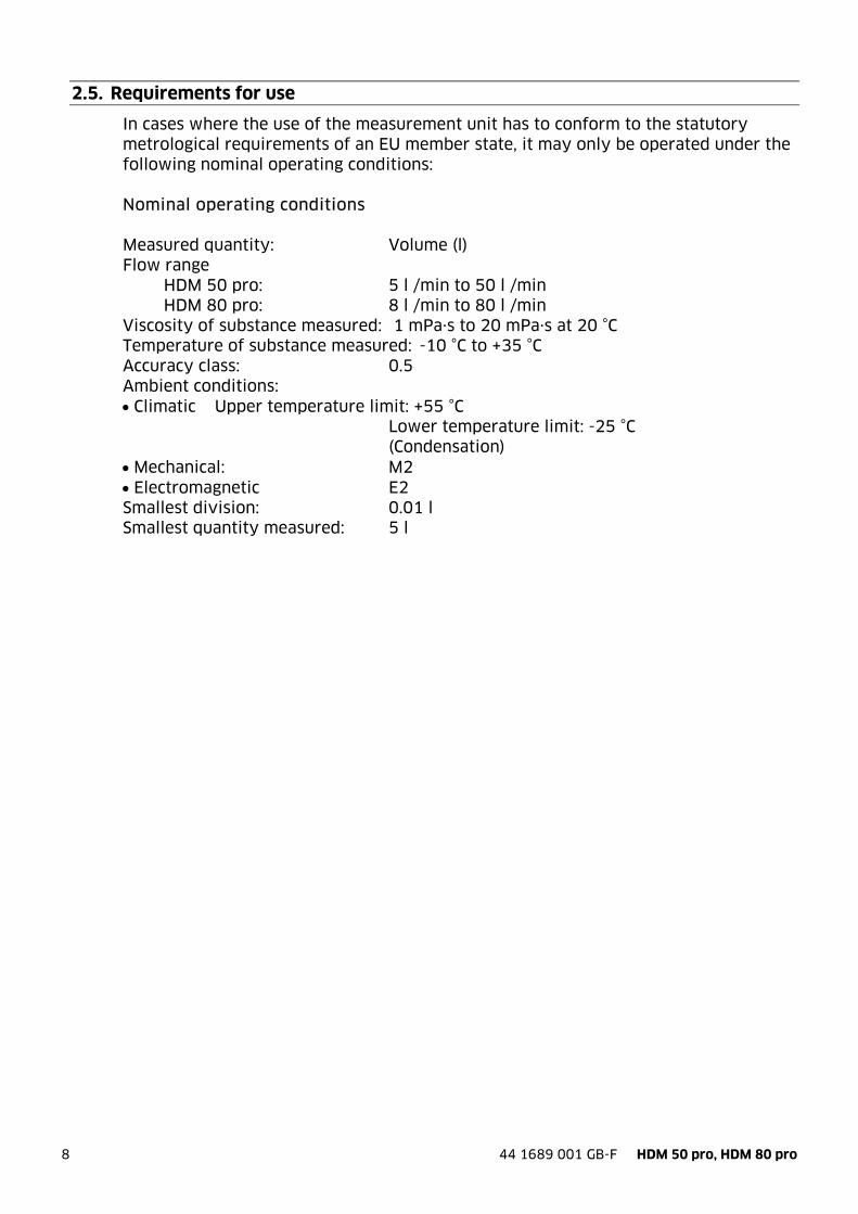
2.5. Requirements for use
In cases where the use of the measurement unit has to conform to the statutory metrological requirements of an EU member state, it may only be operated under the following nominal operating conditions: Nominal operating conditions Measured quantity: Volume (l) Flow range HDM 50 pro: 5 l /min to 50 l /min HDM 80 pro: 8 l /min to 80 l /min Viscosity of substance measured: 1 mPa·s to 20 mPa·s at 20 °C Temperature of substance measured: -10 °C to +35 °C Accuracy class: 0.5 Ambient conditions: Climatic Upper temperature limit: +55 °C Lower temperature limit: -25 °C (Condensation) Mechanical: M2 Electromagnetic E2 Smallest division: 0.01 l Smallest quantity measured: 5 l
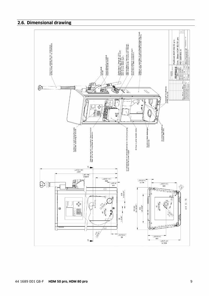
44 1689 001 GB-F HDM 50 pro, HDM 80 pro 9
2.6. Dimensional drawing

10 44 1689 001 GB-F HDM 50 pro, HDM 80 pro
2.7. Suction connections
2.8. Accessories
The following accessories are available for the HDM pro dispenser Description Art. no.: Base frame 233400370 Spring mast 233400325 Angled non-return valve 1 1/4" Incl. Pressure relief mechanism for underground
tank 233400188
Angled non-return valve 1 1/4" Incl. Siphon protection and pressure relief mechanism for aboveground tank
233400182
Floating switch* 233400165 Level probe interface (In the case of orders for upgrades, please
indicate factory number and year of construction of dispensing station)
233400450
Fee for activation code* (Activation by telephone for upgrade with fill level sensor)
233400470
200 mbar level probe* (Max. tank height: 2 m; cable length 5 m) 224010000 300 mbar level probe* (Max. tank height: 3 m; cable length 5 m) 224020000 500 mbar level probe* (Max. tank height: 3 m; cable length 7 m) 224050000 Terminal box with pressure equalization filter*
(For extending cable on level probes) 224061000
LAN connection* (Add-on board; in the case of orders for
upgrades, please indicate factory number and year of construction of dispensing station)
233400031 WiFi connection* 233400034 GPRS module * 233400037 RS422 interface* 233400170 RS232 interface* 233400190 TAG* (Key fob for contactless driver/vehicle
identification) 233400200
USB flash drive with HD Manager eco*
PC software for data evaluation and configuration of the HDA pro automatic dispenser
616700001
HD Manager 8, full version* 233500351 HD Manager 8, server version* 233500402
*only for dispensing stations with HDA pro automatic dispenser
Suction port: Flange joint for Elaflex-DN 40 corrugated pipe. Customer's suction line min. DN 40.
44 1689 001 GB-F HDM 50 pro, HDM 80 pro 11
3. Installation instructions
3.1. Legal
The dispensing station fulfills the water quality and commercial requirements as laid out in the German Water Resources Act (WHG), the Ordinance on Installations for the Handling of Substances Hazardous to Water (VAwS), the Ordinance on Industrial Safety and Health (BetrSichV) and the Technical Regulations for Combustible Liquids (TRbF). The operator is to update himself on and comply with local regulations for installation and operation, as well as obtain the required permits. Installation, commissioning and maintenance may only be performed by licensed specialist companies in accordance with art. 19l of the Water Resources Act (WHG) or by qualified personnel in accordance with the relevant local regulations.
Outside the scope of the abovementioned regulations, the operator is to ensure that all prevailing regulations and technical regulations for the setting up, installation and operation of the dispensing station are adhered to.
3.2. Installation site
The dispensing station has been conceived for outdoor operation. An installation site is to be chosen such that detrimental environmental conditions (e.g. seawater, road salt) do not adversely affect the components. The device is to be installed, affixed onto and operated on a level, load-bearing surface. For space requirements, see chapter 0. The dispensing station has four bore holes in its base frame which are to be used to mount the column. Depending on the on-site structural conditions, the column may also be mounted using heavy-duty dowels suitable for the ground it is to be mounted on. Alternatively, the optionally available base frame may also be used (see chapter 2.8).
The device may not be used in explosion hazard areas!
The operator is to ensure that all regional structural regulations complied with; e.g. sealed road surfaces that are impermeable to liquids, oil separator etc.
3.3. Installation of pipes
3.3.1. Installation of suction line
The suction line for aboveground and underground storage tanks are to comply with at least DN 32. The suction head and the length of the suction line significantly influence the delivery rate of the dispensing station. In order for the dispensing station to provide an optimal flow rate, the suction line is to be kept as short and streamlined as possible. The maximum permissible suction head is 4 m. For suction lines up to a length of 10 m, DN32 is recommended. For longer suction lines, the diameter is to be increased.
In the case of longer suction lines and greater suction heads, an additional connection for an external vacuum pump may be required, with which the initial priming is facilitated.
A suitable on-site siphon protection valve is to be installed for aboveground tanks.

12 44 1689 001 GB-F HDM 50 pro, HDM 80 pro
For all installations, pressure relief of the dispensing station must be possible via the suction line. Non-return valves are not to be installed in the suction line without a pressure relief mechanism. On-site, precautions are to be taken to ensure that pressures exceeding the delivery pressure of the pump cannot arise in the suction line due to e.g. thermal expansion.
It must be ensured that no dirt or foreign objects are able to enter the pump and the meter. For this purpose, a suction filter has been installed in the suction line.
The installation of a corrugated pipe or another suitable elastic compensating element between the pump flange and suction line is necessary for a connection with strain relief. Otherwise, damages to the lines and/or excessive noise emissions cannot be ruled out.
When installing the suction line, ensure that it does not come into contact with housing components.
The operator is to ensure that all regional structural regulations complied with; e.g. double-walled suction lines etc.
For questions on the laying of the suction line, please contact HORN TECALEMIT's customer service.
3.3.2. Return line and venting
For discharging gases and/or foam from the venting line in systems with aboveground tanks, a return line complying with at least DN6 is to lead back into the tank from the dispensing station. In the case of systems with underground tanks, the gases and/or foam can be discharged into the collection reservoir provided; otherwise, a return line is to be laid.
The collection reservoir is to be checked at regular intervals and to be emptied as and when required.
3.3.3. Installation diagram for suction and return lines
We recommend that the suction and return lines be installed as follows:
Aboveground tank – Variant A: Magnetic ventilation valve
The suction line is outfitted with a foot valve (check valve). An electroless, open magnetic valve is mounted on a T-piece at the highest point of the suction line. A line from the magnet valve leads to the air space above the liquid level of the tank. The magnetic valve is connected in parallel with the pump motor. A return line is installed as described in chapter 3.3.2.
44 1689 001 GB-F HDM 50 pro, HDM 80 pro 13
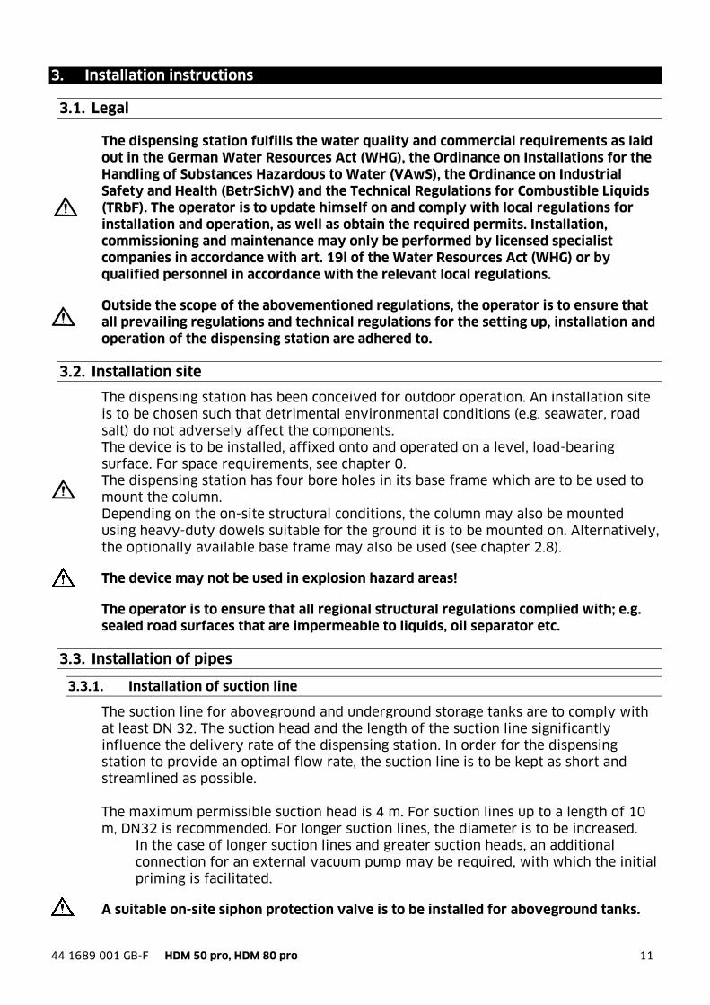
Underground tank – Variant A: Siphon protection check valve
A check valve with siphon protection for the corresponding height is installed at the highest point of the suction line. A pressure relief mechanism is to be installed in order to prevent an unacceptable pressure increase due to e.g. an increase in the temperature of the medium in the suction line (see diagram). A suitable valve is available as an accessory: See chapter 2.8
A return line is installed as described in chapter 3.3.2.
In the case of high tanks (= high opening pressure on the siphon protection valve), an additional connection for an external vacuum pump may be required in order to facilitate the initial priming, or it must be possible to reduce the opening pressure for the initial priming.
14 44 1689 001 GB-F HDM 50 pro, HDM 80 pro
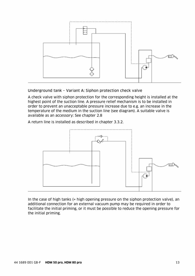
Underground tank: Angled check valve
In the case of underground tanks, a check valve with a low opening pressure is installed in the suction line. The valve is to have a pressure relief mechanism. A suitable valve is available as an accessory: See chapter 2.8
A return line may be installed as described in chapter 3.3.2, or the provided collection flask is to be used.
3.4. Electricity supply
Work on the unit's electrical equipment may only be done by a certified electrician or trained personnel under the guidance and supervision of a certified electrician, and must be done in accordance with the relevant regulations for electrical equipment.
For error-free operation, an electrical connection from a breaker panel with a residual-current device is to be chosen!
The electrical connections are to be done according to the wiring diagram (see Appendix A). In the case of an aboveground tank connection, openings in the rear base are present for cable connections. In the case of an underground tank connection, an opening in the bottom plate is provided. (Also see "Dimension sheet" (Chapter 2.6)). Depending on the variant of the processing unit installed, data interfaces, level probes etc. can be connected. Please refer to the instruction manuals for the associated components. Some variants of the HDM pro have an additional terminal box for connecting the data line (see chapter 4).

44 1689 001 GB-F HDM 50 pro, HDM 80 pro 15
4. HDM pro components
The configuration of the HDM pro is as shown in the following diagram:
4.1. Terminal box
The terminal box in the housing contains:
• 3-step switch with the positions
a. System on
b. System off
c. Emergency operation on
• Start switch and stop switch for emergency operation
3-step switch
Emergency operation switch
Viewing glass (only legally calibratable versions)
Dispensing hose
Drip bottle for oil
Pump unit
Display + keyboard
(depending on computer)
Electrical connection box
Electric motor Suction line
Drip tray
USB port (only HDA pro)
Terminal box Data cable

16 44 1689 001 GB-F HDM 50 pro, HDM 80 pro
4.2. The 4-piston measuring device
The 4-piston measuring device keeps track of the quantity dispensed.
With the help of the calibration wheel, the distance of travel of the piston can be modified, thereby adjusting the measurement accuracy. In the case of non-legally calibratable variants, the user may perform this calibration. In the case of legally calibratable variants, the calibration is to take place as part of a precalibration procedure, and/or must take place as part of an official calibration. Always try to calibrate the HDM using the electronic system.
In non-legally calibratable versions, the integrated single pulse generator is used. In legally calibratable versions, a calibratable double pulse generator is mounted on the measuring device.
4-piston measuring device with pulse generator (legally calibratable)
Calibration wheel
Pulse generator (legally calibratable)

44 1689 001 GB-F HDM 50 pro, HDM 80 pro 17
4.3. Pump unit in detail
The compact pump unit installed in the device comprises the following elements:
Pump unit Side view
Overflow valve
Gas separator
Dry bleed

18 44 1689 001 GB-F HDM 50 pro, HDM 80 pro
4.4. Pump unit components
The following image shows the components of the pump block:
In the side view (right side when installed), you will see the openings for the gear pump and the filter.
Pump unit Components
Dry bleed
Pressure port
Pump unit Components View of right side
Filter
Pressure port
44 1689 001 GB-F HDM 50 pro, HDM 80 pro 19
5. Commissioning/operation
5.1. Initial commissioning and recommissioning
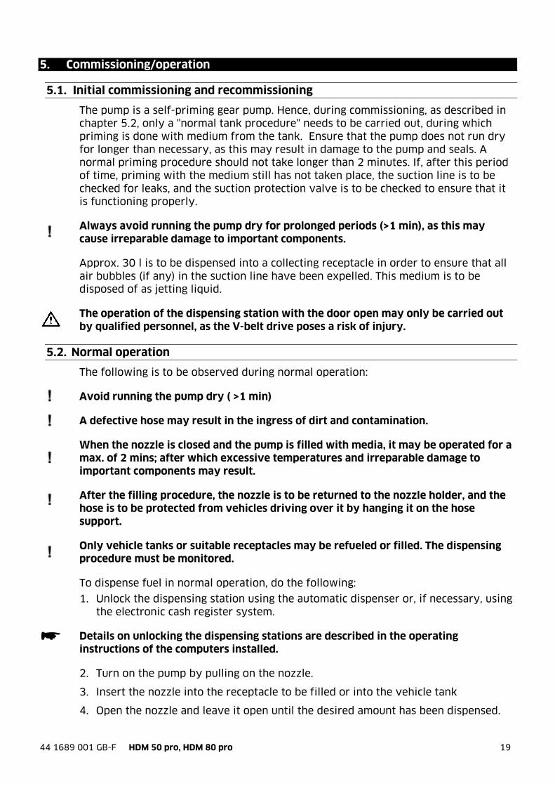
The pump is a self-priming gear pump. Hence, during commissioning, as described in chapter 5.2, only a "normal tank procedure" needs to be carried out, during which priming is done with medium from the tank. Ensure that the pump does not run dry for longer than necessary, as this may result in damage to the pump and seals. A normal priming procedure should not take longer than 2 minutes. If, after this period of time, priming with the medium still has not taken place, the suction line is to be checked for leaks, and the suction protection valve is to be checked to ensure that it is functioning properly.
Always avoid running the pump dry for prolonged periods (>1 min), as this may cause irreparable damage to important components.
Approx. 30 l is to be dispensed into a collecting receptacle in order to ensure that all air bubbles (if any) in the suction line have been expelled. This medium is to be disposed of as jetting liquid.
The operation of the dispensing station with the door open may only be carried out by qualified personnel, as the V-belt drive poses a risk of injury.
5.2. Normal operation
The following is to be observed during normal operation:
Avoid running the pump dry ( >1 min)
A defective hose may result in the ingress of dirt and contamination.
When the nozzle is closed and the pump is filled with media, it may be operated for a max. of 2 mins; after which excessive temperatures and irreparable damage to important components may result.
After the filling procedure, the nozzle is to be returned to the nozzle holder, and the hose is to be protected from vehicles driving over it by hanging it on the hose support.
Only vehicle tanks or suitable receptacles may be refueled or filled. The dispensing procedure must be monitored.
To dispense fuel in normal operation, do the following:
1. Unlock the dispensing station using the automatic dispenser or, if necessary, using the electronic cash register system.
Details on unlocking the dispensing stations are described in the operating instructions of the computers installed.
2. Turn on the pump by pulling on the nozzle.
3. Insert the nozzle into the receptacle to be filled or into the vehicle tank
4. Open the nozzle and leave it open until the desired amount has been dispensed.

20 44 1689 001 GB-F HDM 50 pro, HDM 80 pro
You can use the catch to lock the nozzle lever in place (hold it open). The automatic nozzle shuts off the flow automatically when the tank is full. If you would like to end the dispensation procedure before this happens,
a. release the nozzle lever (if it has not been locked in place)
b. If the lever has been locked in place, pull it up and then release it.
The dispensation procedure must be monitored constantly!
5. Return the nozzle to the nozzle holder immediately after the nozzle has been shut off. The pump turns off automatically.
Please also refer to the operating instructions for the nozzle and/or chapter 6.
5.3. Emergency operation
If the price calculator, liter counter or automatic dispenser has stopped working, dispensation can still take place in emergency operation mode.
In this case, it will not be possible to calculate or measure the quantity dispensed.
To dispense fuel in emergency operation mode, do the following:
1. Remove the door of the housing.
The operation of the dispensing station with the door open may only be carried out by qualified personnel, as the V-belt drive poses a risk of injury.
2. Turn the 3-step switch to "Emergency operation" This will enable you to start and stop
the pump in emergency operation.
3. Press on "Start" in the switching cabinet to start the dispensation.
4. Insert the nozzle into the receptacle to be filled or into the vehicle tank
3-step switch
Emergency operation switch
Terminal box Operating switches
44 1689 001 GB-F HDM 50 pro, HDM 80 pro 21
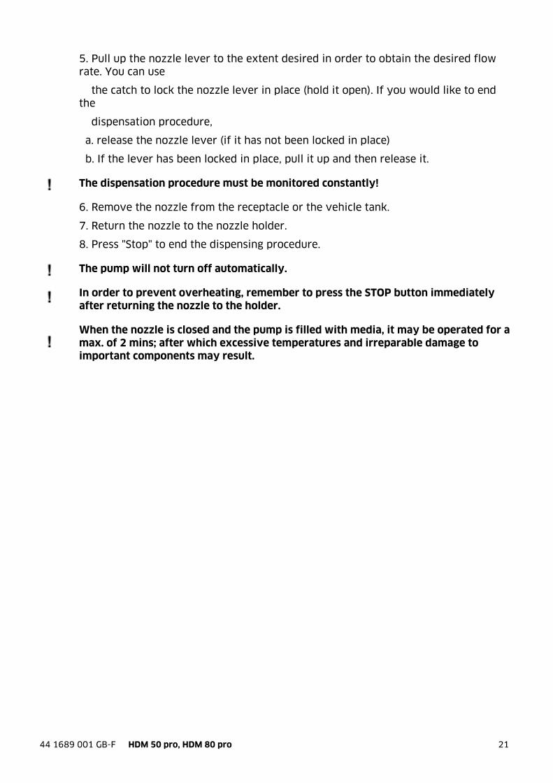
5. Pull up the nozzle lever to the extent desired in order to obtain the desired flow rate. You can use
the catch to lock the nozzle lever in place (hold it open). If you would like to end the
dispensation procedure,
a. release the nozzle lever (if it has not been locked in place)
b. If the lever has been locked in place, pull it up and then release it.
The dispensation procedure must be monitored constantly!
6. Remove the nozzle from the receptacle or the vehicle tank.
7. Return the nozzle to the nozzle holder.
8. Press "Stop" to end the dispensing procedure.
The pump will not turn off automatically.
In order to prevent overheating, remember to press the STOP button immediately after returning the nozzle to the holder.
When the nozzle is closed and the pump is filled with media, it may be operated for a max. of 2 mins; after which excessive temperatures and irreparable damage to important components may result.
22 44 1689 001 GB-F HDM 50 pro, HDM 80 pro
6. Automatic nozzle
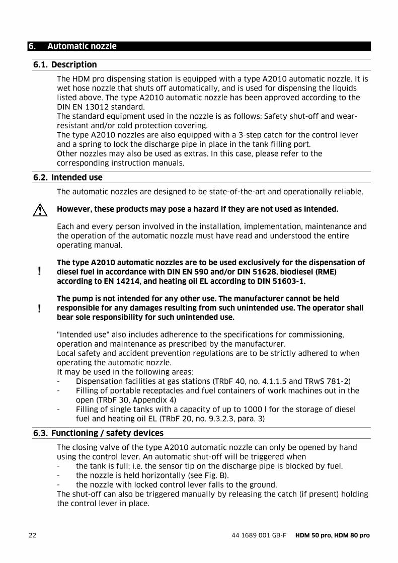
6.1. Description
The HDM pro dispensing station is equipped with a type A2010 automatic nozzle. It is wet hose nozzle that shuts off automatically, and is used for dispensing the liquids listed above. The type A2010 automatic nozzle has been approved according to the DIN EN 13012 standard. The standard equipment used in the nozzle is as follows: Safety shut-off and wear-resistant and/or cold protection covering. The type A2010 nozzles are also equipped with a 3-step catch for the control lever and a spring to lock the discharge pipe in place in the tank filling port. Other nozzles may also be used as extras. In this case, please refer to the corresponding instruction manuals.
6.2. Intended use
The automatic nozzles are designed to be state-of-the-art and operationally reliable.
However, these products may pose a hazard if they are not used as intended.
Each and every person involved in the installation, implementation, maintenance and the operation of the automatic nozzle must have read and understood the entire operating manual.
The type A2010 automatic nozzles are to be used exclusively for the dispensation of diesel fuel in accordance with DIN EN 590 and/or DIN 51628, biodiesel (RME) according to EN 14214, and heating oil EL according to DIN 51603-1.
The pump is not intended for any other use. The manufacturer cannot be held responsible for any damages resulting from such unintended use. The operator shall bear sole responsibility for such unintended use.
"Intended use" also includes adherence to the specifications for commissioning, operation and maintenance as prescribed by the manufacturer. Local safety and accident prevention regulations are to be strictly adhered to when operating the automatic nozzle. It may be used in the following areas: - Dispensation facilities at gas stations (TRbF 40, no. 4.1.1.5 and TRwS 781-2) - Filling of portable receptacles and fuel containers of work machines out in the
open (TRbF 30, Appendix 4) - Filling of single tanks with a capacity of up to 1000 l for the storage of diesel
fuel and heating oil EL (TRbF 20, no. 9.3.2.3, para. 3)
6.3. Functioning / safety devices
The closing valve of the type A2010 automatic nozzle can only be opened by hand using the control lever. An automatic shut-off will be triggered when - the tank is full; i.e. the sensor tip on the discharge pipe is blocked by fuel. - the nozzle is held horizontally (see Fig. B). - the nozzle with locked control lever falls to the ground. The shut-off can also be triggered manually by releasing the catch (if present) holding the control lever in place.
44 1689 001 GB-F HDM 50 pro, HDM 80 pro 23
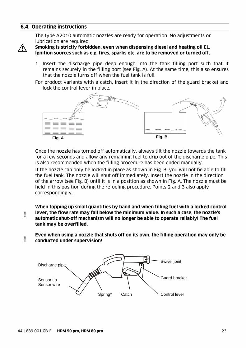
Fig. A
6.4. Operating instructions
The type A2010 automatic nozzles are ready for operation. No adjustments or lubrication are required. Smoking is strictly forbidden, even when dispensing diesel and heating oil EL. Ignition sources such as e.g. fires, sparks etc. are to be removed or turned off.
1. Insert the discharge pipe deep enough into the tank filling port such that it remains securely in the filling port (see Fig. A). At the same time, this also ensures that the nozzle turns off when the fuel tank is full.
For product variants with a catch, insert it in the direction of the guard bracket and lock the control lever in place.
Once the nozzle has turned off automatically, always tilt the nozzle towards the tank for a few seconds and allow any remaining fuel to drip out of the discharge pipe. This is also recommended when the filling procedure has been ended manually.
If the nozzle can only be locked in place as shown in Fig. B, you will not be able to fill the fuel tank. The nozzle will shut off immediately. Insert the nozzle in the direction of the arrow (see Fig. B) until it is in a position as shown in Fig. A. The nozzle must be held in this position during the refueling procedure. Points 2 and 3 also apply correspondingly.
When topping up small quantities by hand and when filling fuel with a locked control lever, the flow rate may fall below the minimum value. In such a case, the nozzle's automatic shut-off mechanism will no longer be able to operate reliably! The fuel tank may be overfilled.
Even when using a nozzle that shuts off on its own, the filling operation may only be conducted under supervision!
Discharge pipe
Sensor tip Sensor wire
Spring* Catch Control lever
Guard bracket
Swivel joint
Fig. B

24 44 1689 001 GB-F HDM 50 pro, HDM 80 pro
7. Fault display – What to do if ... ?
... the pump runs, but the automatic nozzle immediately shuts off again? The sensor pipe of the automatic nozzle is clogged: The nozzle must be cleaned.
... the pump runs, but no medium is pumped? Storage tank is empty: hang up the nozzle immediately and refill the tank Air has entered the suction line: hang up the nozzle immediately and fill the
suction line as described above. ...when the pump does not start up after the nozzle has been removed?
Flap of nozzle switch is stiff: Lubricate as described below. Variants with automatic dispenser: The dispensing station has been locked due
to too many zero dispensations: See the operating instructions for the dispensing station
Variants with price calculator / liter counter: The station is not unlocked: See the operating instructions for the processing unit
The motor protection switch has been triggered: Resolve the source of the error and switch system on again.
... The pumps is operating, but too little media is pumped? The suction-side filter is dirty and must be cleaned. The V-belt slips due to insufficient tension.

44 1689 001 GB-F HDM 50 pro, HDM 80 pro 25
8. Maintenance
For any maintenance the valid and applicable accident prevention regulations must be observed. Disconnect the device from the power supply and depressurise it when carrying out maintenance work. Secure it against being unintentionally switched on. Maintenance and repair work may only be carried out by specially-trained service technicians. Although the HDM eco dispenser is to a large extent maintenance-free, the following work should be performed regularly in order to ensure reliable operation.
8.1. Regular inspections / maintenance work
Components Checks / maintenance operations
Mo
nth
ly
An
nu
ally
Aft
er 1
mil
lio
n
lite
rs
As
nee
de
d /
up
on
m
alfu
nct
ion
Automatic pump nozzle Check functioning of automatic mechanism
X X
Pump nozzle holder Clean with water and non-aggressive household cleaner
X X
Lubricate switch flap with resin-free spray oil
X X
Dispensing hose Check the dispensing hose for damages and increased wear
X X
Hydraulic components Visually inspect system for leaks X X Housing Clean with water and non-
aggressive household cleaner; check for damage to paintwork + corrosion — if necessary, renew corrosion protection
X X
V-belt Check tension and check for damage
X X
Filter Clean as described below X X The maintenance intervals are maximum periods that must be shortened in the case of difficult operating conditions (e.g. heavy use, careless users).
8.1.1. Cleaning the system
Clean dirty outsides carefully with a damp cloth and gentle household cleaner. Do not use aggressive (e.g. abrasive, chlorinated) cleaning agents or solvents. The equipment must not be cleaned with a high-pressure cleaner or water jet.
8.1.2. Maintenance of the nozzle
Make sure that the sensor jet on the outlet pipe is always open. The nozzle does not work if the sensor jet is dirty. Any dirt particles can be removed using a suitable wire. Greasing or oiling is not necessary.
8.1.3. Replacing the back-up battery
Some variants of the processing unit have a back-up battery that needs to be replaced regularly. For further information, please refer to the operating instructions of the processing unit installed.
26 44 1689 001 GB-F HDM 50 pro, HDM 80 pro
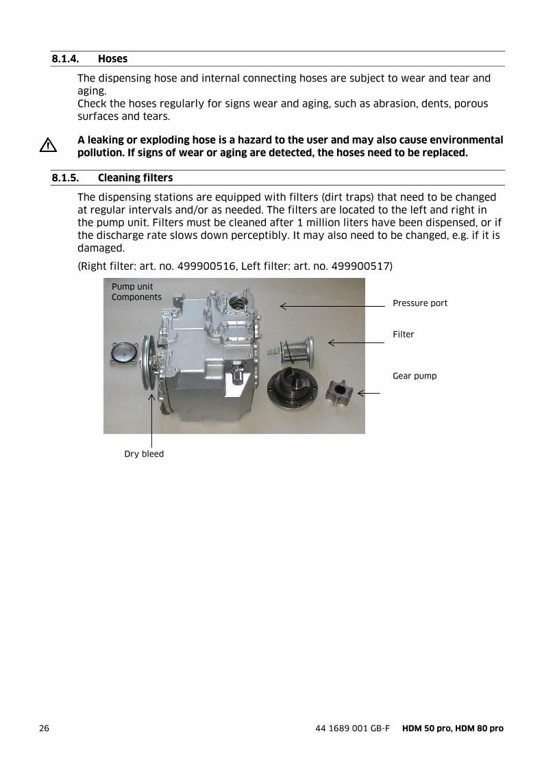
Pressure port Filter Gear pump
Dry bleed
8.1.4. Hoses
The dispensing hose and internal connecting hoses are subject to wear and tear and aging. Check the hoses regularly for signs wear and aging, such as abrasion, dents, porous surfaces and tears.
A leaking or exploding hose is a hazard to the user and may also cause environmental pollution. If signs of wear or aging are detected, the hoses need to be replaced.
8.1.5. Cleaning filters
The dispensing stations are equipped with filters (dirt traps) that need to be changed at regular intervals and/or as needed. The filters are located to the left and right in the pump unit. Filters must be cleaned after 1 million liters have been dispensed, or if the discharge rate slows down perceptibly. It may also need to be changed, e.g. if it is damaged.
(Right filter: art. no. 499900516, Left filter: art. no. 499900517)
Pump unit Components

44 1689 001 GB-F HDM 50 pro, HDM 80 pro 27
Float 1
Float 2
8.1.6. Float valve
The pump unit is outfitted with a float valve that needs to be checked to ensure that it is functioning properly when the gas separator malfunctions. To do so, open the chamber and check the mobility of the float.
8.1.7. V-belt
The tension of the V-belt needs to be checked at regular intervals. If signs of damage or wear are noticeable on the V-belt, it is to be replaced. The tension of the V-belt must be checked if it starts emitting noise and/or at the very latest, after 1 million liters have been dispensed.
8.1.8. Type Plate and Warning Signs
The warning signs attached to the device and the type plate must be well legible. Dirty signs must be cleaned, and replaced if necessary.
8.2. Repairs and customer service
The HDM was developed with the goal of enabling operation with the lowest possible maintenance costs. You can achieve this by operating the device in accordance with this instruction manual. However, if you require our services, please contact our Horn customer service.
Pump unit With both floats

28 44 1689 001 GB-F HDM 50 pro, HDM 80 pro
9. Spare Parts
9.1. Housing
44 1689 001 GB-F HDM 50 pro, HDM 80 pro 29
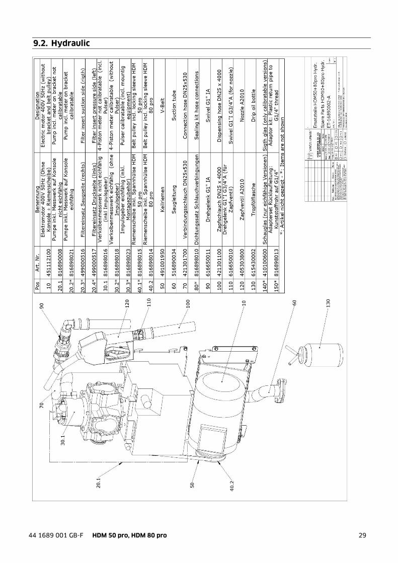
9.2. Hydraulic
30 44 1689 001 GB-F HDM 50 pro, HDM 80 pro
10. Disposal
The device is to be emptied completely and the liquids properly disposed of in case it is taken out of service. The equipment is to be disposed of properly when taken permanently out of service:
- Return old metal for recycling. - Return plastic parts for recycling. - Return electronic waste for recycling.
The water legal regulations are to be followed.
10.1. Return of batteries
Batteries must not be disposed of with the domestic waste. Batteries can be returned free of charge via a suitable collecting point or to the dispatch stores. Consumers are legally obliged to return used batteries. Batteries that contain harmful substances are marked with a crossed out dustbin (see above) and the chemical symbol (Cd, Hg or Pb) of the heavy metal that is decisive for the classification as containing harmful substances: 1. “Cd” stands for cadmium. 2. “Pb” stands for lead. 3. “Hg” stands for mercury.

44 1689 001 GB-F HDM 50 pro, HDM 80 pro 31
Appendix A. Wiring diagram
32 44 1689 001 GB-F HDM 50 pro, HDM 80 pro
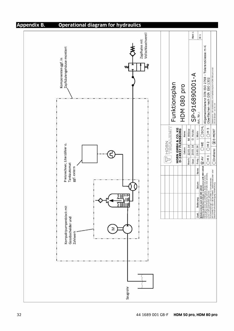
Appendix B. Operational diagram for hydraulics
44 1689 001 GB-F HDM 50 pro, HDM 80 pro 33
Appendix C. Declaration of conformity of the A2010 nozzle Horn GmbH & Co. KG hereby declares the conformity of the A2010 automatic nozzle to DIN EN 13012 and the general building authority test certificate P-TÜ7-01340.
34 44 1689 001 GB-F HDM 50 pro, HDM 80 pro
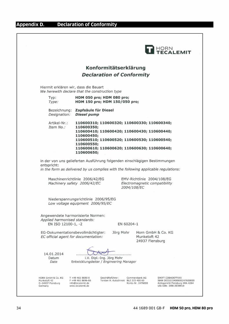
Appendix D. Declaration of Conformity

44 1689 001 GB-F HDM 50 pro, HDM 80 pro 35

36 44 1689 001 GB-F HDM 50 pro, HDM 80 pro
HORN GmbH & Co. KG Munketoft 42 24937 Flensburg Deutschland T +49 461-8696-0 F +49 461-8696-66 www.tecalemit.de [email protected]