Embed Size (px)
Citation preview

Kentucky Construction Site BMP Planning and Technical Specifications Manual 41
4.3 Site Preparation
Initial clearing and grading work on a site requires attention to a fairly common set of general goals:
• Minimize site disturbance to preserve and maintain existing vegetative cover
• Limit the number of access points to the site to control off-site mud tracking
• Phase and sequence construction activities by dividing the project into logical work zones
• Locate temporary and permanent soil disposal areas, haul roads, and construction staging areas to minimize erosion, sediment transport, and disturbance to existing vegetation
• Install sediment barriers and controls before land clearing and grading wherever possible
• Get to final grade, seed and mulch as soon as you can
Construction site work includes clearing, grading, and preparing the site for built features like roads, utilities, buildings, parking lots, and the site drainage system. This section covers a broad range of site preparation tasks including land grading, installation of the construction exit, topsoil storage, identifying buffer zones around drainage features, and initial preparation of soil surfaces by roughening.
For more information about designing construction projects that cost less and minimize water resource impacts, see the Low Impact Development Design Strategies guide posted at www.epa.gov/owow/nps/lid/lidnatl.pdf, or see the Best Management Practices Manual for Erosion Prevention and Sediment Control published by the Kentucky MS4 Work Group, posted at www.bgky.org/publicworks/planningdesign/bmpindex.htm.
The normal sequence for basic site preparation work begins with the installation of controls before clearing and excavation work and ends with all bare areas covered with grass, gravel, or built surfaces, and stable ditches with functioning stormwater systems (see table that follows).
Planning the clearing, grubbing, and site preparation work is necessary, especially for larger sites. Written plans—even very basic ones—help to ensure that everyone understands where the active work zones are, various activity phases, and the schedule.
Contractors and equipment operators should understand erosion control plans developed by engineers and be prepared to adapt the controls as the job progresses. Key control points are areas of concentrated runoff and sheet runoff. Make sure the design, location, schedule, installation, and maintenance of BMPs is logged in the KPDES permit files if the site has a disturbed area of one acre or more.

42 Technical Specifications for BMPs
Typical Construction Phasing Schedule for Site Preparation Work
Construction Activity Scheduling Considerations
Identify work zones and construction phases by analyzing proposed cut/fill work, location of proposed structures, site conditions, and site resources
Construction phase and work zone identification will ensure that land clearing and grading exposes a minimum amount of soil at any one time.
Identify and flag off areas to be protected, such as buffer zones near creeks or sinkholes, drainage features, vegetated filter strips, mature trees, and so on.
All areas should be flagged and posted before land clearing and grading begins.
Install construction entrance/exit and designate vehicle parking areas
First land disturbing activity. Use geotextile liner under rock to maintain effectiveness; stabilize bare areas as soon as possible.
Install upgradient diversion swales or berms. Seed and mulch as soon as construction of swales or berms is completed.
Size and install sediment barriers (e.g., silt fences), sediment traps, sediment basins, and outlet protection.
Install principal sediment basin(s) first; install other basins and traps as needed during clearing/grading or construction.
Install inlet protection dams, dikes, filters, screens, and such.
Applies to all curb, drop, pipe, or other inlets.
Construct drainage / runoff conveyance system; stabilize ditches and culvert outlets.
Seed and mulch as soon as possible. Use triple seeding (see seeding rates in Section 4.4.1) in ditches, and blankets/mats as necessary. Ensure that drainage entering streams or other waterbodies does not cause sedimentation.
Begin clearing, grubbing, and grading. Strip and grade areas only as needed. Get to final grade and apply seed and mulch as soon as possible. Direct runoff toward appropriate controls; install new controls as needed.
Stabilize bare areas after final grade is reached.
Apply temporary or permanent seed, mulch, or other controls as soon as work is completed, but no later than 14 days after grading work in each area is finished.
Construct roads, buildings, parking lots and install utilities.
Install runoff controls as needed to deal with muddy runoff, rutting, and such.
Install landscaping and other final features. Stabilize all bare areas and ditches. Remove all temporary controls.
Maintenance Inspect and maintain controls weekly and after each rain of one-half inch or more.
Designating a logical progression for active project work zones and phasing work within those zones helps to minimize the area requiring erosion and sediment controls. Try to match cut and fill needs to minimize disturbed area and material handling.
BMP Plan preparers and work crews should understand that controls change as the site is graded and construction proceeds. For example, fiber rolls (logs) can control sediment along curbs and roads in relatively flat residential developments, rather than silt fences, which function well in large areas of sheet runoff but are often moved or damaged on small lot applications.

Kentucky Construction Site BMP Planning and Technical Specifications Manual 43
4.3 Site Preparation
4.3.1 Land Grading
DefinitionOperations that remove vegetation—such as clearing and grubbing—and reshape the surface of the land through excavation or placement of fill material.
PurposeLand grading serves to construct designed site drainage features, achieve site grades necessary for construction of roads, buildings, parking lots, and other site features.
Design Criteria • All borrow and fill or disposal areas should be noted on the BMP Plan.
• A phased clearing and grading schedule that minimizes the extent of the denuded areas and minimizes the length of time the areas are exposed should be developed and followed.
• Existing drainage features (e.g., swales, ditches, channels) and the vegetation nearby should be preserved wherever possible.
• Finished cut and fill slopes to be vegetated should not be steeper than 3H:1V unless erosion control blankets or turf reinforcement mats are used.
• Cuts or fills should not be so close to property lines as to endanger adjoining property—adequate protection against erosion, sedimentation, slippage, settlement, subsidence, and other damage must be implemented.
• Subsurface drainage should be provided to areas having high water tables to intercept seepage that might affect slope stability.
• Ditches and other drainage system features should be designed to safely convey increased runoff from cleared or developed areas without causing downstream channel aggradation, degradation, or increased off-site flooding.
• The site should be graded to direct flows to appropriate BMPs or other controls.
• Temporary structural controls (e.g., silt fencing, ditch checks, inlet dikes) installed during construction must be designed to accomplish maximum stabilization and control of erosion and sedimentation and must be installed, maintained, and removed according to the specifications set forth in this manual.
The goal for land grading is to install necessary controls before clearing or cut/fill work, then get to final grade and seed/mulch as quickly as possible. Protect slopes and concentrated flow areas with extra controls as needed.

44 Technical Specifications for BMPs
• All permanent structural controls, including drainage facilities such as channels, storm sewer inlets, and detention basins, must be designed according to the standards set forth in this manual.
Construction Specifications • Drainage system controls (e.g., sediment traps/basins, ditches) and perimeter controls
(silt fences, construction exit) should be installed before land grading.
• No fill may be placed where it can slide or wash onto adjoining property unless proper erosion and sediment control measures and proper stabilization is provided.
• No fill may be placed adjacent to creek channel banks where it can cause bank failure, reduce stream flow capacity, or wash into creeks unless proper erosion and sediment control measures and proper stabilization is provided.
• Brush cleared from the site can be used as a temporary downgradient sediment barrier if placed on the contour to intercept and detain muddy runoff.
• Stabilized construction entrances must be located and used at all points of ingress/egress on a construction site. The transfer of soil, mud and dust onto public rights-of-ways must be prevented.
• Whenever construction dewatering operations are required on a site, they must be conducted according to the specifications set forth in this manual and according to KPDES requirements if discharging to a ditch or waterbody.
• Crossings of waterways during construction must be minimized and covered under the appropriate USACE section 404 permit. Encroachment into stream buffers, riparian areas, and wetlands must be avoided.
• Topsoil must be stockpiled and preserved from erosion or dispersal both during and after site grading operations.
• Cut and fill slopes should be seeded and mulched (or covered with blankets/mats) immediately after construction (i.e., within 14 days).
• Where construction or land disturbance activity will or has temporarily ceased on any portion of a site, temporary site stabilization measures must be required as soon as practicable, but no later than 14 calendar days after the activity has ceased.
• Final stabilization of the site must be required within 14 calendar days of construction completion.
The following sensitive features should be noted on site maps and plans:
• Local Regulatory Floodplain and Conveyance Zone, as defined by local ordinances (see local planning and zoning or public works office).
• Stream and river corridors (including blue line and intermittent), as mapped by United States Geological Survey on 7.5 minute topographic maps.
• Karst features with a well-defined surface opening, such as a cave, sinkhole, vadose shaft, or other karst feature.
• Lakes and impoundments and their dams and spillways.
• Jurisdictional wetlands as determined by the USACE or that meet USACE designation criteria.
• Slopes greater than 25% (4H:1V).• Erodible and severely erodible soils, as
determined by the Natural Resources Conservation Service.
• Sites with the potential to drain stormwater directly into a sensitive feature listed above (including any designated buffer area for that feature) or into a designated greenway.
Kentucky Construction Site BMP Planning and Technical Specifications Manual 45
Inspection and Maintenance
• Inspect ditches and other areas where runoff exits the site for rutting or evidence of muddy flows. Install BMPs (e.g., silt traps, sediment barriers) as needed.
• Inspect perimeter controls where sheet runoff exits the site for silt fence undercutting, bypassing, or damage. Repair existing controls or install new ones as needed.
• Inspect sediment traps and basins and other drainage system controls weekly and after rainfall of one-half inch or more to verify available sediment storage capacity.
• Inspect construction exit to ensure that no mud tracking onto the paved road is occurring.
• Check flagged areas to ensure that no damage or other impacts are occurring in stream buffers or other protected areas.
• Inspect cleared and excavated areas continuously to check for the presence of underground pipelines, tanks, sinkholes, or other unforeseen features.
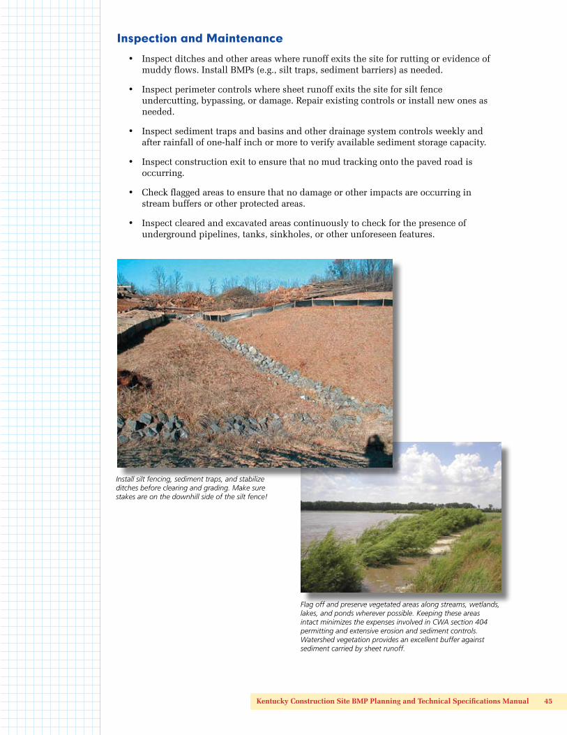
Install silt fencing, sediment traps, and stabilize ditches before clearing and grading. Make sure stakes are on the downhill side of the silt fence!
Flag off and preserve vegetated areas along streams, wetlands, lakes, and ponds wherever possible. Keeping these areas intact minimizes the expenses involved in CWA section 404 permitting and extensive erosion and sediment controls. Watershed vegetation provides an excellent buffer against sediment carried by sheet runoff.
46 Technical Specifications for BMPs
4.3 Site Preparation
4.3.2 Construction Exit
DefinitionA construction exit is a stabilized pad of 2-inch or larger rock at any point where vehicles or equipment leave a construction site and enter a public right-of-way, street, alley, sidewalk, or parking area.
PurposeA stabilized construction exit is intended to reduce off-site sedimentation and improve public safety by eliminating the tracking or other movement of sediment onto public rights-of-way.
Design Criteria
Construction plans must limit traffic exiting the site to properly constructed and stabilized construction exits.
• The entrance must be constructed at a location that minimizes the impact to streams and storm drains and maximizes public safety.
• The aggregate size for construction of the pad must be 2–3 inch stone, at a minimum (KYTC No. 1 or No. 2, not 57s or DGA).
• The thickness of the pad must not be less than 6 inches. Use geotextile fabrics below the rock, if necessary, to improve stability of the foundation in locations subject to seepage or high water table.
• The width of the pad must not be less than the full width of all points of ingress or egress and, in any case, must not be less than 12 feet wide. Allow for necessary turning radii for trucks and equipment. The length of the pad must be as required, but not less than 50 feet.
Construction Specifications • Construct rock construction exit before clearing, grubbing, and grading the site.
Place the gravel to the specific grade and dimensions shown on the plans, and level it out. A geotextile underliner helps to keep rock up out of the mud and functioning properly to remove mud from vehicle and equipment tires.
• Construction entrances will be located as shown on the development plans, or as directed by approving regulatory agency. Any deviation from this location must receive regulatory agency approval.
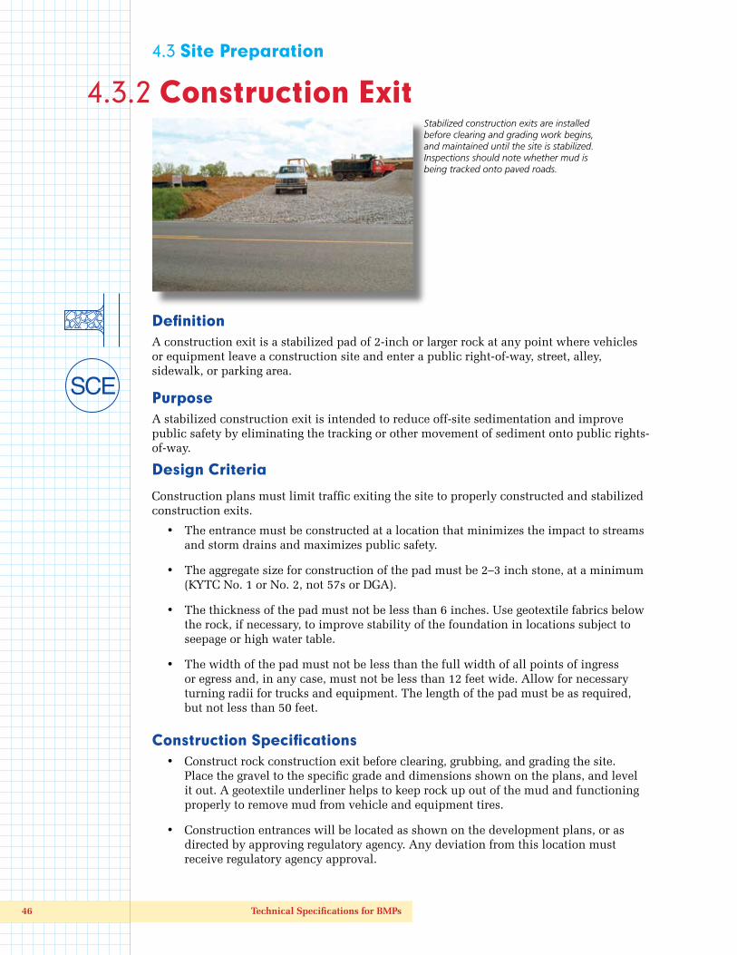
Stabilized construction exits are installed before clearing and grading work begins, and maintained until the site is stabilized. Inspections should note whether mud is being tracked onto paved roads.
Kentucky Construction Site BMP Planning and Technical Specifications Manual 47
• Provide drainage to direct muddy runoff from the construction exit toward a sediment trap or other controlled area. In no case should muddy runoff from the construction exit flow onto roads, parking lots, or adjacent properties.
• When necessary, wheels must be cleaned with a shovel, scraper, or high-pressure water hose to remove sediment before entrance onto roads or other paved areas. When washing is required, it must be done on an area stabilized with KYTC No. 1 or No. 2 rock that drains into an approved sediment trap or sediment basin.
Inspection and MaintenanceInspect all construction exits twice a day during dry weather and more often during wet weather. Encourage equipment operators and other personnel to immediately report any mud tracking onto paved off-site areas.
• All sediment spilled, dropped, washed or tracked onto public rights-of-way must be removed immediately.
• The entrance must be maintained in a condition that will prevent tracking or flowing of sediment onto public rights-of-way. This could require periodic top dressing with additional stone as conditions demand, and repair or maintenance of any measures used to trap sediment.
• Replace gravel material when surface voids are filled with soil, or use a grubbing rake mounted to a front-end loader to stir the rock during dry conditions and shake down fine soil particles.
• Sediment from construction entrances and exits must be prevented from entering any storm drain, ditch, or watercourse through use of sediment traps, sand bags, commercial sediment dikes, inlet filters, or other approved methods. Maintain traps or other sediment trapping structures as needed.
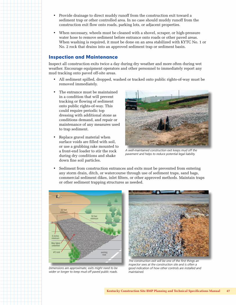
Dimensions are approximate; exits might need to be wider or longer to keep mud off paved public roads.
The construction exit will be one of the first things an inspector sees at the construction site and is often a good indication of how other controls are installed and maintained.
A well-maintained construction exit keeps mud off the pavement and helps to reduce potential legal liability.

48 Technical Specifications for BMPs

Kentucky Construction Site BMP Planning and Technical Specifications Manual 49
4.3 Site Preparation
4.3.3 Temporary Diversion (Berm or Ditch)
DefinitionA temporary berm, ditch, or channel constructed above an area of exposed soil.
PurposeTemporary diversion is intended to divert clean upland runoff or drainage water away from unprotected disturbed areas and toward a vegetated infiltration area, stabilized ditch, or other stabilized outlet.
Design CriteriaLocate diversion berms and ditches to intercept and carry runoff around or through bare soil areas as needed. Berms should be located to minimize damage by construction operations and traffic.
• Berms and ditches should be designed to carry the 10-year, 24-hour peak flow.
• Side slopes should be 2H:1V or flatter.
• Freeboard should be at least 0.5 feet.
• Berms and ditches should be stabilized with triple-seeded grass (see seeding rates in Section 4.4.1) and mulch or an erosion control blanket, turf reinforcement mat, or rock. For information on stabilizing ditches of varying slopes, see Sections 4.6.5–4.6.7.
Construction SpecificationsTemporary diversion berms or ditches must be installed as a first step in the land-disturbing activity and must be functional before downslope land disturbance.
• The berm must be adequately compacted to prevent failure.
• Temporary or permanent seeding and mulch must be applied to the berm or ditch immediately following its construction. Triple-seed areas below the flow line, and use erosion control blankets or turf reinforcement mats as needed.
Use berms, ditches, fiber rolls, or other diversions to direct upslope water away from the disturbed area. This helps to reduce the amount of muddy runoff that controls must handle.

50 Technical Specifications for BMPs
Inspection and MaintenanceInspect berms and ditches weekly and after every rainfall greater than one-half inch and after any repairs are made to the berm or flow channel. Check to make sure that berm or ditch is stable and outlet or infiltration areas are not eroding.
• If vegetation has not been established, reseed damaged and sparse areas immediately. Triple seed (see seeding rates in Section 4.4.1) areas below the flow line, and use erosion control blankets or turf reinforcement mats as necessary.
• Damages caused by construction traffic or other activity must be repaired before the end of each working day.
Diversion berms can be temporary or permanent. Make sure they are seeded and mulched immediately after construction. The upslope swale alongside steep berms might need an erosion control blanket to prevent scouring (for drainage system controls, see Section 4.5).
Stabilize diversion ditches by triple-seeding and mulching. Use nets or blankets if slopes are long (> 50 ft) and exceed 2 percent.
Stable diversion ditch protects slope during excavation and afterwards. Note spreader configuration of ditch discharge point, which helps dissipate flows.
Diversion berm directing runoff toward sediment trap: Controlling sheet runoff with berms and ditches ensures that flows are managed appropriately and provides the framework for a system of sediment traps and basins on larger sites.

Kentucky Construction Site BMP Planning and Technical Specifications Manual 51
52 Technical Specifications for BMPs
4.3 Site Preparation
4.3.4 Topsoil Stockpiling
DefinitionStockpiling is the salvaging, storing, protecting, and use of topsoil to enhance final site stabilization and support selected vegetation.
PurposeThe purpose of topsoil stockpiling is to provide a suitable growth medium for vegetation. It should be used where the subsoil or areas of existing surface soil present the following problems:
• The structure, pH, or nutrient balance of the available soil cannot be amended by reasonable means to provide an adequate growth medium for the desired vegetation.
• The soil is too shallow to provide adequate rooting depth or will not supply necessary moisture and nutrients for growth of desired vegetation.
• The soil contains substances toxic to the desired vegetation.
• Stockpiling should also be used where high-quality turf or ornamental plants are desired and where slopes are 2H:1V or flatter.
Topsoil is the surface layer of the soil profile, generally characterized as darker than the subsoil because of enrichment with organic matter. It is the major zone of root development and biological activity—microorganisms that enhance plant growth thrive in this layer. Topsoil can usually be differentiated from subsoil by texture as well as color. Clay content usually increases in the subsoil. Where subsoils are often high in clay, the topsoil layer can be significantly coarser in texture. The depth of topsoil can be quite variable. On severely eroded sites, it might be gone entirely.
Advantages of topsoil over subsoil include its high organic-matter content and friable consistence (soil aggregates can be crushed with only moderate pressure) and its available water-holding capacity and nutrient content. The texture and friability of topsoil provide benefits to seedlings the growth of their roots. In addition to being a better growth medium, topsoils are often less erodible than subsoils, and the coarser texture of topsoil increases infiltration capacity and reduces runoff.
Although topsoil can provide an improved growth medium, there could be disadvantages, too. Stripping, stockpiling, hauling, and spreading topsoil or importing topsoil might not be cost effective. Handling can be difficult if large amounts of branches or rocks are present, or if the terrain is rough. Most topsoil contains weed seeds that compete with desirable species.
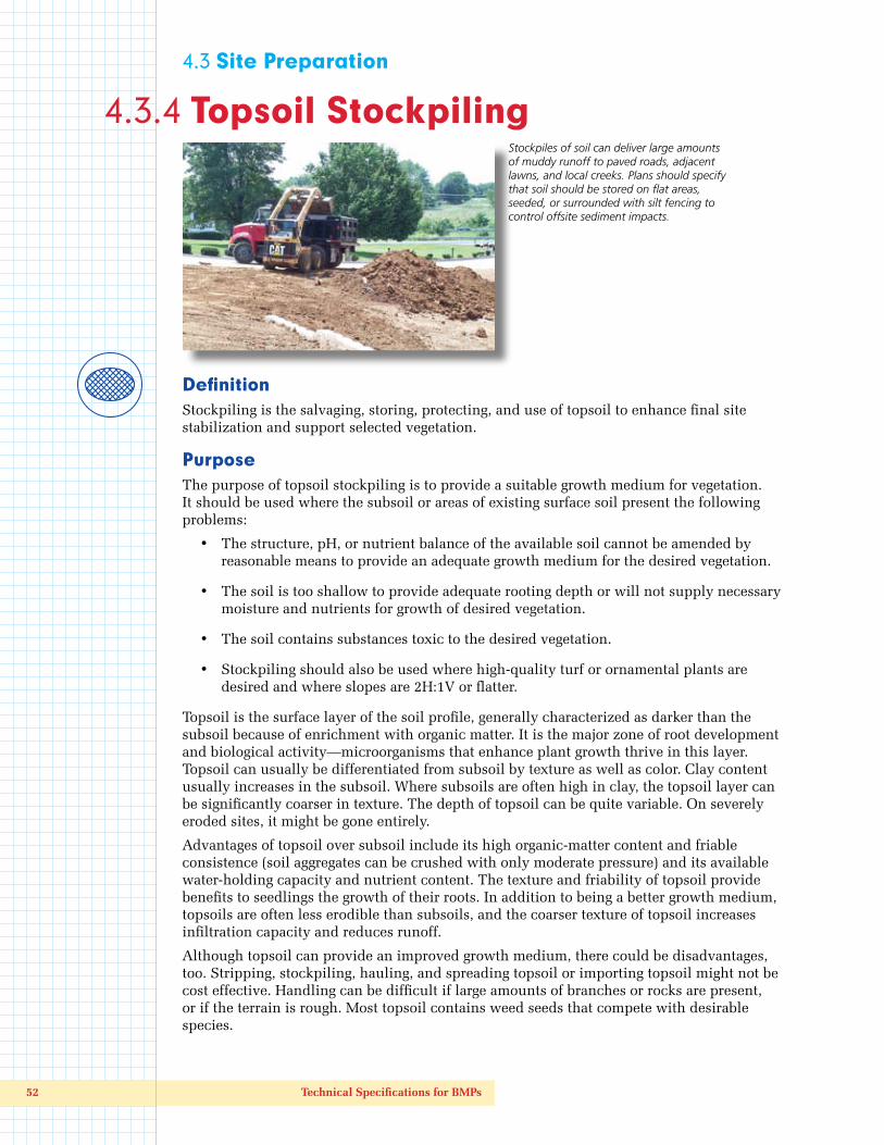
Stockpiles of soil can deliver large amounts of muddy runoff to paved roads, adjacent lawns, and local creeks. Plans should specify that soil should be stored on flat areas, seeded, or surrounded with silt fencing to control offsite sediment impacts.

Kentucky Construction Site BMP Planning and Technical Specifications Manual 53
In site planning, compare the options of stockpiling with preparing a seedbed in the available subsoil. The clay content of many subsoils retains moisture. When properly limed and fertilized, subsoils can provide a satisfactory growth medium that is generally free of weed seeds. Stockpiling is normally recommended where ornamental plants or high-maintenance turf will be grown. It might also be required to establish vegetation on shallow soils, soils containing potentially toxic materials, stony soils, and soils of critically low pH (high acidity).
Design Criteria
If topsoil is to be stockpiled, consider the following:
• Quality and amount of topsoil available and needed.
• Location for a stabilized stockpile that will not erode, block drainage, or interfere with work on the site. Topsoil stockpiles should be on flat ground if possible, and protected by a silt fence or other sediment barrier on the downgradient sides. Topsoil that will not be used for more than 21 days should be mulched or seeded.
• If topsoil and subsoil are not properly bonded, water will not infiltrate the soil profile evenly, and it will be difficult to establish vegetation. To promote bonding, scarify or rip subsoil to a depth of 8–12 inches; do not compact during topsoil placement operations.
• Do not apply topsoil to slopes steeper than 2:1 to avoid slippage, or to a subsoil of highly contrasting texture. Sandy topsoil over clay subsoil is a particularly poor combination, especially on steep slopes. Water can creep along the junction between the soil layers and cause the topsoil layer to slip or slough.
Cubic Yards of Topsoil Required to Attain Various Soil Depths
Depth (Inches) Per 1,000 Square Feet Per Acre
1 3.1 134
2 6.2 268
3 9.3 403
4 12.4 537
5 15.5 672
6 18.6 806
Construction SpecificationsMaterials
Quality topsoil has the following characteristics:
The best texture is loam, sandy loam, and silt loam. Sandy clay loam, silty clay loam, clay loam, and loamy sand are fair. Do not use heavy clay and highly organic soils such as peat or muck as topsoil.
Organic matter content should be greater than 1 percent by weight.
Liming is required if pH is less than 6.0.
The depth of material meeting the above qualifications should be at least 2 inches. Soil factors such as rock fragments, slope, depth to water table, and layer thickness affect the ease of excavation and spreading of topsoil.
Generally, the upper part of the soil that is richest in organic matter is most desirable; however, material excavated from deeper layers could be worth storing if it meets the other criteria listed above.

54 Technical Specifications for BMPs
Organic soils such as mucks and peats do not make good topsoil. They can be identified by their extremely light weight when dry.
Stripping
Strip topsoil from only those areas that will be disturbed by excavation, filling, road building, or compaction by equipment. A 4–6 inch stripping depth is common but depth varies depending on the site. Determine depth of stripping by taking soil cores at several locations within each area to be stripped. Topsoil depth generally varies along a gradient from hilltop to toe of slope. Put sediment basins, diversions, and other controls into place before stripping.
Stockpiling
Select stockpile location to avoid slopes, flood plains, natural channels, and traffic routes. Stockpiles should be placed away from water bodies to prevent sedimentation. On large sites, re-spreading is easier and more economical when topsoil is stockpiled in small piles near areas where they will be used.
Use silt fences or other barriers where necessary to retain sediment.
Protect topsoil stockpiles by temporarily seeding as soon as possible, and for no longer than 14 days if the stockpile is idle.
If stockpiles will not be used within 2 months, they should be stabilized with permanent vegetation to control erosion and weed growth.
Site Preparation
Before spreading topsoil, establish erosion and sedimentation control practices such as diversions, berms, and sediment basins.
Maintain grades on the areas to be topsoiled according to the approved plan. Adjust grades and elevations for receipt of topsoil.
Where the pH of the existing subsoil is 6.0 or less, or the soil is composed of heavy clays, incorporate agricultural limestone in amounts recommended by soil tests or specified for the seeding mixture to be used. Incorporate lime to a depth of at least 2 inches by disking.
Immediately before spreading the topsoil, loosen the subgrade by disking or scarifying to a depth of at least 4 inches to ensure bonding of the topsoil and subsoil. If no amendments have been incorporated, loosen the soil to a depth of at least 6 inches before spreading topsoil.
Spreading Topsoil
Uniformly distribute topsoil to a minimum compact depth of 2 inches on 3:1 slopes and 4 inches on flatter slopes. Do not spread topsoil while it is frozen or muddy or when the subgrade is wet or frozen.
Correct any irregularities in the surface that result from stockpiling or other operations to prevent the formation of depressions or water pockets.
Compact the topsoil enough to ensure good contact with the underlying soil, but avoid excessive compaction as it increases runoff and inhibits seed germination. Light packing with a roller is recommended where high-maintenance turf is to be established.
On slopes and areas that will not be mowed, the surface may be left rough after spreading topsoil. A disk may be used to promote bonding at the interface between the topsoil and subsoil.
After topsoil application, follow procedures for temporary or permanent seeding, taking care to avoid excessive mixing of topsoil into the subsoil.
This is a good location of topsoil pile on flat, grassy area and good use of a silt fence to protect nearby creek (foreground).

Kentucky Construction Site BMP Planning and Technical Specifications Manual 55
4.3 Site Preparation
4.3.5 Surface Roughening
DefinitionSurface roughening is a technique for creating horizontal depressions, furrows, or other roughened surfaces on bare ground using tracked or other equipment.
PurposeSurface roughening is intended to aid the establishment of vegetative cover from seed, reduce runoff velocity, increase infiltration, reduce erosion, and to provide for sediment trapping. All construction slopes require surface roughening to facilitate long-term stabilization with vegetation, particularly slopes that are steeper than 3H:1V.
Rough slope surfaces are preferred because they aid the establishment of vegetation, improve water infiltration, and decrease runoff velocity. Graded areas with smooth, hard surfaces can be initially attractive, but such surfaces increase the potential for erosion. A rough, loose soil surface is more favorable for rain infiltration and moisture retention than hard, smooth surfaces; this aids in seed germination.
Design CriteriaThere are different methods for achieving a roughened soil surface on a slope, and the selection of an appropriate method depends upon the type of slope. Roughening methods include stair-step grading, furrowing, and tracking. Factors to consider in choosing a method are slope steepness, mowing requirements, and whether the slope is formed by cutting or filling.
Roughening techniques that call for indentations, furrows, ridges, stair-step grading (small benches), and so forth (see table) should specify that all these features be perpendicular to the direction of flow (i.e., across the slope rather than up and down). Surface roughening should be specified for all slopes at final grade and those not being actively worked as detailed below in the Construction Specifications section.
Soil Conditions vs. Erosion
If soil is: Erosion will be:
Compacted and smooth 30 percent more
Tracks across slopes 20 percent more
Tracks up & down slopes 10 percent less
Rough and irregular 10 percent less
Rough & loose to 12" deep 20 percent less
Specify surface roughening for bare areas that will be prepared for seeding and sodding. Roughening improves soil-to-seed contact and reduces erosion on slopes.

56 Technical Specifications for BMPs
Construction SpecificationsCut Slope Roughening
• Stair-step grade or groove all cut slopes that are steeper than 3H:1V.
• Use stair-step grading on any erodible material soft enough to be ripped with a bulldozer. Slopes consisting of soft rock with some subsoil are particularly suited to stair-step grading.
• Make the vertical cut distance less than the horizontal distance, and slightly slope the horizontal position of the step in toward the vertical wall.
• Do not make individual vertical cuts more than 2 feet high in soft materials or more than 3 feet high in rocky materials.
• Groove the slope using machinery to create a series of ridges and depressions that run across the slope, on the contour.
Fill Slope Roughening
• Place fill slopes with a gradient steeper than 3H:1V in lifts not to exceed 8 inches, and make sure each lift is properly compacted.
• Ensure that the face of the slope consists of loose, uncompacted fill 4–6 inches deep.
• Use grooving or tracking to roughen the face of the slopes, if necessary. Grooves and track indentions must be perpendicular to the direction of downslope flow.
• Apply seed, fertilizer, and straw mulch then track or punch in the mulch with the bulldozer.
• Do not blade or scrape the final slope face.
Cuts, Fills, and Graded Areas
• Make mowed slopes no steeper than 3H:1V.
• Roughen these areas to shallow grooves by normal tilling, disking, harrowing, or use a cultipacker-seeder. Make the final pass of any such tillage on the contour (i.e., across the slope rather than up and down).
• Make grooves formed by such implements close together (less than 10 inches, and not less than 1 inch deep).
• Excessive roughness is undesirable where mowing is planned.
Roughening With Tracked Machinery
• Limit roughening with tracked machinery to soils with a sandy textural component to avoid undue compaction of the soil surface. Tracking soils with heavy clay content can cause compaction and seal the slope soils, increasing runoff and making seed germination difficult.
• Operate tracked machinery up and down the slope to leave horizontal depressions in the soil. Do not back-blade during the final grading operation.
• Immediately seed and mulch roughened areas to obtain optimum seed germination and growth. Use erosion control blankets or turf reinforcement mats on long (> 50 feet) steep (> 2H:1V) slopes as necessary, or hydroseed.
Inspection and MaintenancePeriodically check the seeded slopes for rills and washes. Fill these areas slightly above the original grade, then reseed and mulch or cover with blanket or mat as soon as possible.

Kentucky Construction Site BMP Planning and Technical Specifications Manual 57