Embed Size (px)
Citation preview
IEEE TRANSACTIONS ON CIRCUITS AND SYSTEMS-11: ANALOG AND DIGITAL SIGNAL PROCESSING, VOL. 43, NO. 5 , MAY 1996 387
A Multiplier-Free Digital Sinusoid Generator Based on Sigma-Delta Modulation
Clemens M. Zierhofer
Abstract-In this paper sigma-delta (%A) sequences derived from a single-loop numeric E-A modulator with sinusoidal input are investigated. A class of limit cycles shows :a special kind of symmetry, designated as "half-symmetry". It is shown that half- symmetric E-A sequences are especially suited for automatic generation by means of an autonomous oscillator. The design of such an oscillator is presented. The central part is a single- loop numeric E-A modulator. The two-level output sequence of the E-A modulator is accumulated in lossless discrete integrators and fed back to the input. If the initial conditions of the oscillator registers are chosen properly in relation to a system constant F , the oscillator generates a two-level E-A sequence identical to the sequence of a S A modulator which is externally driven by a pure sinusoid. Conditions for system constant E and initialization for periodic operation are derived. If constant F i s an integer, the operation of the oscillator is exclusively based aln integers. Thus, although the network is highly recursive, truncation- or round- off errors are avoided and problems with respect to stability do not occur.
I. INTRODUCTION N PRINCIPLE, digital sinusoids can be generated exclu- I sively from a table look-up scheme, from a recursion, or
from a combination of table look-up and computation. Purely recursive generation requires digital networks with recursive (or IIR-) structures. A general feature of recursive networks is truncation- or round-off errors due to limited computation precision and thus digital oscillators based on icecursion usually tend to unstable operation. An example of a recursive digital sinusoid generator is a cascade of two discrete-time integrators with z-transforms z-'/(l-z-') and l/(l-z--'), respectively, and a multibit-multiplier in a loop. The oscillation frequency is determined by the multiplier factor, and the oscillation amplitude is defined by the initial conditions of the registers. A description of an oscillator based on this concept has been published in [l].
The digital oscillator described in [2] essentially utilizes the double-integration topology of the oscillator [ 11. However, the multibit-multiplier is replaced by a sigma-delta ( E A ) modulator, which is incorporated between the integrators. In [2], the basic operation parameters of the oscillator such as oscillation frequency and amplitude are exclusively derived from the double-integration oscillator without taking into account the E A modulator. It is assumed that the E-A modulator works fully equivalently to a mudiplier (plus one
Manuscript received June 20, 1994; revised June 26, 1995. This paper was
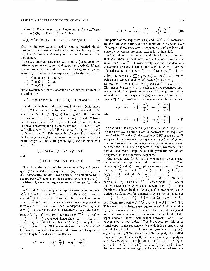
The author is with the Institute for Applied Physics, Univeristy of Innsbruck,
Publisher Item Identifier S 1057-7130(96)03755-X.
recommended by Associate Editor D. A. Johns.
A-6020 Innsbruck, Austria.
unit delay stage) and therefore the noise introduced in the quantization stage of the modulator has no influence on the stability of oscillation. This assumption is justified by experiment, but not by theory.
This paper presents a E-A based oscillator similar to the oscillator circuit as described in [2]. The oscillator is analyzed and conditions for guaranteed stable oscillation modes are derived. It is shown in Section IV-C of this paper that this type of oscillator is highly sensitive to variations of system parameters; only small changes in the initial conditions of the registers may lead to unstable operation modes.
The digital oscillator analyzed in this paper contains a single-loop numeric E-A modulator. The oversampling E A modulation concept is primarily known for its suitability for high-performance analog-to-digital (AD)- and digital-to- analog (D/A) conversion [3]. In the E-A-modulator, the analog input signal is converted to a two-level output sequence (y-sequence) at a rate f s which is much higher than the Nyquist rate 2 f c (fc is the signal bandwidth). The ratio & is usually designated as oversampling ratio (OSR). In the time domain, the amplitude of the input signal is represented in the y-sequence as the short-time mean value. In the frequency do- main, the spectrum of the y-sequence consists of the spectrum of the input signal in the base band plus the spectrum of the noise signal (due to the noise added at the quantization stage). Because of the noise-shaping properties inherent in the E A concept, most of the energy of the noise spectrum is shifted outside the signal band toward higher frequencies. However, as far as the signal band is concerned, the representation of the input signal in the y-sequence is not perfect, since some noise energy remains in the base band and introduces a systematic error (finite signal-to-noise ratio). As a general feature of AD- conversion, this imperfection in signal representation can be interpreted as an uncertainty about the input signal. This means that a particular y-sequence can be generated not only by one single specific input signal, but also by slightly deviating input signals.
This general property is exploited in the E-A oscillator analyzed in this paper. A method is presented to derive conditions for the oscillator to generate periodic y-sequences identical to the y-sequences of a E-A modulator which is externally driven by a pure sinusoid. Although the input signal of the E-A modulator within the resonator loop is not perfectly harmonic, it is possible to obtain identity of the y-sequences in the light of the considerations mentioned above.
This paper is organized as follows. In Section 11, y- sequences are investigated when a discrete-time %A
1057-7130/96$05,00 0 1996 IEEE
38X IEEE TRANSACTIONS ON CIRCUITS AND SYSTEMS-11: ANALOG AND DIGITAL SIGNAL PROCESSING, VOL. 43, NO. 5 , MAY 1996
Y o b > 0
(b)
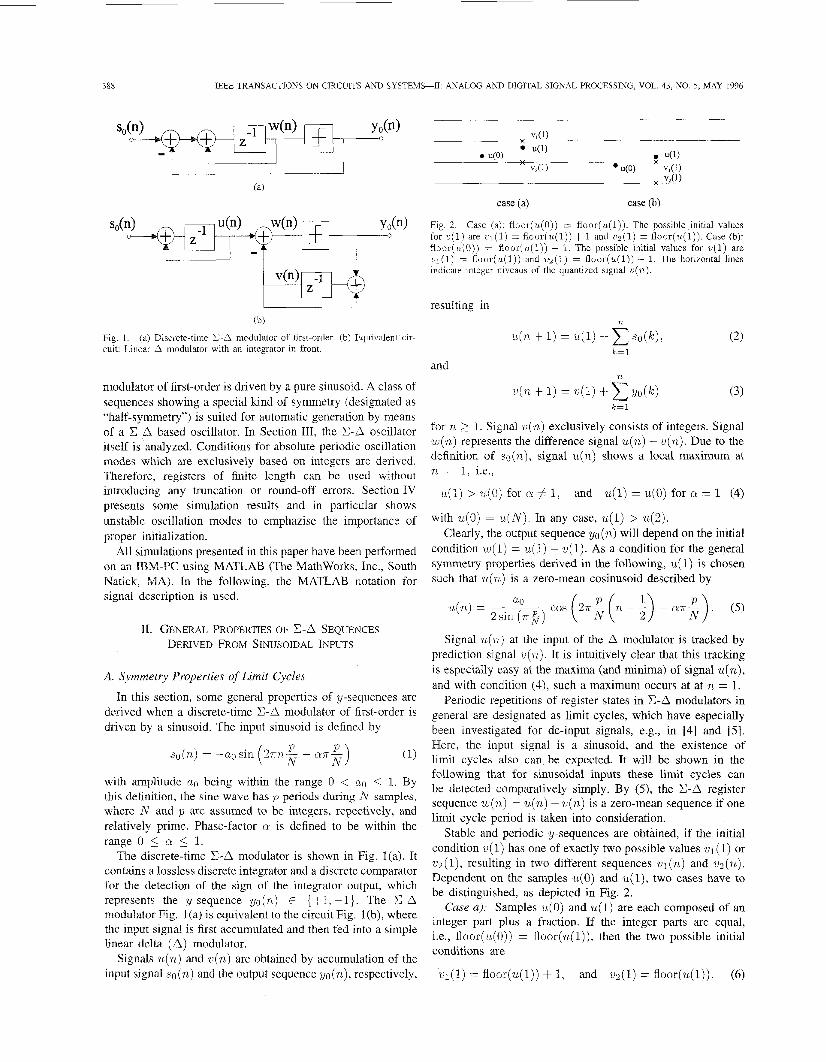
Fig. 1. cuit: Linear A modulator with an integrator in front.
(a) Discrete-time S A modulator of first-order. (b) Equivalent cir-
modulator of first-order is driven by a pure sinusoid. A class of sequences showing a special kind of symmetry (designated as “half-symmetry”) is suited for automatic generation by means of a E A based oscillator. In Section 111, the E A oscillator itself is analyzed. Conditions for absolute periodic oscillation modes which are exclusively based on integers are derived. Therefore, registers of finite length can be used without introducing any truncation or round-off errors. Section IV presents some simulation results and in particular shows unstable oscillation modes to emphazise the importance of proper initialization.
All simulations presented in this paper have been performed on an IBM-PC using MATLAB (The Mathworks, Inc., South Natick, MA). In the following, the MATLAB notation for signal description is used.
11. GENERAL PROPERTIES OF E A SEQUENCES DERIVED FROM SINUSOIDAL INPUTS
case (a) case (b)
Fig. 2. Case (a): f loor(u(0)) E floor(u(1)). The possible initial values for ~ ( 1 ) are c l (1) = f loo r (u ( l ) )+ 1 and v2(1) = floor(u(1)). Case (b): floor(u(0)) = fioor(u(1)) - 1. The possible initial values for v(1) are ~ ~ ( 1 ) = floor(u(1)) and v z ( 1 ) = floor(u(1)) - 1. The horizontal lines indicate integer niveaus of the quantized signal v ( n ) .
resulting in
and
n
u(n + I) = u(1) + s o ( k ) , k=l
n
v(n + 1) = 41) -I- Yo(k) ( 3 ) k=l
for n 2 1. Signal w ( n ) exclusively consists of integers. Signal ~ ( n ) represents the difference signal U(.) - U(.). Due to the definition of so (%) , signal U(.) shows a local maximum at n = 1, i.e.,
and u(1) = u(0) for cr = 1 (4) u(1) > u(0) for Q # 1,
with u(0) = u ( N ) . In any case, u(1) > 4 2 ) . Clearly, the output sequence yo (n) will depend on the initial
condition w(1) = u(1) - ~ ( 1 ) . As a condition for the general symmetry properties derived in the following, U ( 1) is chosen such that U(.) is a zero-mean cosinusoid described by
u(n) =
Signal u(n) at the input of the A modulator is tracked by prediction signal Y (n). It is intuitively clear that this tracking is especially easy at the maxima (and minima) of signal u(n), and with condition (4), such a maximum occurs at at n = 1.
Periodic repetitions of register states in E A modulators in general are designated as limit cycles, which have especially been investigated for dc-input signals, e.g., in [4] and [5] . Here, the input signal is a sinusoid, and the existence of limit cycles also can be expected. It will be shown in the
A. Symmetry Properties of Limit Cycles
In this section, Some general Properties of Y-sequences are derived when a discrete-time c-a modulator Of first-order 1s driven by a sinusoid. The input sinusoid is defined by
( l ) P so(n,) = -aosin 2 ~ n - - QT- ( N N
with amplitude a0 being within the range 0 < a0 1. By this definition, the sine wave has p periods during N samples, where N and p are assumed to be integers, repectively, and relatively prime. Phase-factor a is defined to be within the range 0 5 a 5 1.
The discrete-time E-A modulator is shown in Fig. l(a). It contains a lossless discrete integrator and a discrete comparator for the detection of the sign of the integrator output, which represents the y-sequence yo(n) E {+l, -1}. The E-A modulator Fig. l(a) is equivalent to the circuit Fig. l(b), where the input signal is first accumulated and then fed into a simple linear delta (A) modulator.
Signals U(.) and ~ ( n ) are obtained by accumulation of the input signal s o ( n ) and the output sequence yo (n), respectively,
following that for sinusoidal inputs these limit cycles can be detected comparatively simply. By (3, the E-A register sequence w ( n ) = u(n) - ~ ( n ) is a zero-mean sequence if one limit cycle period is taken into consideration.
Stable and periodic y-sequences are obtained, if the initial condition Y (1) has one of exactly two possible values wI(1) or u2(1), resulting in two different sequences ~ ( n ) and v~(n). Dependent on the samples u(0) and u(l), two cases have to be distinguished, as depicted in Fig. 2.
Case a): Samples u(0) and u(1) are each composed of an integer part plus a fraction. If the integer parts are equal, i.e., floor(u(0)) = floor(u(l)), then the two possible initial conditions are
~ ~ ( 1 ) = floor(u(1)) + I, and ,u2(1) = floor(u(1)). (6)
ZIERHOFER MULTIPLIER-FREE DIGITAL SINUSOID GENERATOR 389
Case b): If the integer parts of u(0) and u(1) are different, i.e., floor(u(0)) = floor(u(1)) - 1, then
q(1) = floor(u(l)), and w2(1) = floor(u(1)) - 1. (7)
Each of the two cases a) and b) can be verified simply looking at the possible predecessors of samples vl(1) and w2(1), respectively, and taking into account the rules of A- modulation.
The two different sequences vl(n) and v2(n) result in two different y-sequences yol(n) and yoz(n), respectively. If u(n) is a zero-mean cosinusoid as described in (3, some general symmetry properties of the sequences can be derived for
i) N mod 2 = 1 (odd N ) , ii) N mod 4 = 2, and
iii) N mod 4 = 0. For convenience, a parity operator on an integer argument q is defined by
P{q} = 0 for even q , and P{q} = 1 for odd q. (8)
ad i): for N being odd, the period of a;(.) (with index i = 1 , 2 here and in the following) cannot be equal to N , since P{wi(N+ l)} # P{v i ( l ) } . Looking at (3), the reason is that necessarily P{x,",l yo;(n)} = P { N } = 1 with N being odd. However, since u ( N + 1) = u(1) and thle considerations of above concerning the possible values for vi(.) at n = 1 are still valid at n = N + 1, it follows that wl(N$- 1) = v ~ ( 1 ) and wz(N + 1) = wl( 1). This means that for n = 1 : 2N, each of the two sequences vi(.) is composed of two partial sequences of the length N , one starting with q ( 1 ) and the other with v2(1), i.e.,
v,1(1:2N) = [w,(l :N) w2(1:N)],
v2(1:2N) = /.2(1:N) v1(1:N)]. (9)
and
Therefore, the period of the sequences U;(.) and conse- quently the period of the sequences w; (n ) = U ( n) - U; (n) is 2N, representing the limit cycle period. The amplitude-DFT- spectra over 2 N samples of the associated y-slequences yo; (n) are identical, since the sequences are equal except for a time shift.
ad ii): if N is an integer multiple of two, it follows that
and U ( % + 1) = -u(1). Thus U(.) has a local minimum at n = $ + 1, and the considerations concerning possible locations for U;(.) at n = 1 can be adapted accordingly at n = $ + 1. However, if N is a multiple of two, but not of four, P{w;(~+l)} # P{wi(l)}, because P{><,"=l y;o(n)} = P { T } = 1 for $ being odd. Since signal w;(n) tracks U(.)
at n = $! + 1, it follows that w ~ ( : + 1) = -vz(l) and v2 ( + 1) = - w1 (1). This means that for n '= 1 : N , each of the two sequences U;(.) is composed of two partial sequences of the length 9 and can be written as
N + 1 : N ) = -u( l : +), and especially ,U($) = -u(0)
N
N
v 1 ( l : N ) = [?Jl(l:;) -w2(1:;)],
and
The period of the sequences .ut(.) and w,(n) is N, represent- ing the limit cycle period, and the amplitude-DFT-spectra over N samples of the associated y-sequences yo,(.) are identical, since the sequences are equal except for a time shift.
ad iii): if N is an integer multiple of four, it follows that U(.) shows a local maximum and a local minimum at n = 1 and n = $ + 1, respectively, and the considerations concerning possible locations for v,(n) at n = 1 can be adapted accordingly at n = $ + 1. Here, P{v,($ + I)} =
P{w,(l)}, because P{C,2=1y~/o,(n)} = P{?} = 0 for being even. Since signals v,(n) track U(.) at n = $ + 1, if follows that w ~ ( $ + 1) = -v l ( l ) and w2(: + 1) = -va(l). This means that for n = 1 : N , each of the two sequences v,(n) is composed of two partial sequences of the length $ and the second half of each sequence v,(n) is obtained from the first by a simple sign inversion. The sequences can be written as
N N
v 1 ( l : N ) = -vl(l:;)],
and
The period of the sequences w, (n) and w, (n ) IS N , represent- ing the limit cycle period. Here, in contrast to the sequences described in (9) and (lo), the amplitude-DFT-spectra over N samples of the associated y-sequences yo, (n) are different. For convenience, the symmetry property within one period as described in (11) is designated as "half-symmetry,'' and periodic sequences composed of half-symmetric periods are designated as half-symmetric sequences.
One special case for N mod 4 = 0 occurs, when phase- factor Q of the input sinusoid is set to Q = 1. Then signals so(n) and u(n) are highly symmetric and it follows that so(1 :N) = [ s o ( l : + ) s o ( $ : - l : l ) - s ~ ( l : $ ) - 30($:-1:1)] and u ( 1 : N ) = [u(l) ~(2::) 0 - u ( T : - 1 : 2 ) -u( l ) - u ( 2 : 7 ) 0 u ( 7 : - 1 : 2 ) ] with zeros at n = + 1. Starting at n = 1, one of the two sequences ut(.) will also be zero at n = % + 1, and therefore the determination of yo, (n) at this location will cause difficulties. Condition for sequence v, (n ) for not being zero at
is different from parity P{C$, yO,(n)} = P{ $} (cf. (3)). This means that $ being even requires an odd initial condition w , ( 1 ) to produce a valid sequence u,(n), and being odd an even initial condition. Depending on the amplitude of the input sinusoid, index i will change between 1 and 2. For convenience, a new index "s" is introduced for this case: signal w,(n) is the sequence w,(n) with index z properly set such that U, ( $ + 1) # 0. The resulting y-sequence is yo, (n). Signal w, (n) in general has a remarkable property: the shifted sequence us (n + 1) has exactly the same symmetry property as u ( n ) , i . e . , ~ , ( 2 : ~ + 1 ) = [vs(2) w3(3:$+1) o -us($ !+ 1 : -1 : 3) -ws(2) -vs(3 : ++l) 0 w , ( ? + l : -1 : 3)]. Since the zero-mean sequences v,(n) and u(n) are derived from the
+ 1 and n = 4
n = + 1 (i.e., P { V , ( ~ N + 1)) = 1) is that parity P{v,(l)}
390 IEEE TRANSACTIONS ON CIRCUITS AND SYSTEMS-11: ANALOG AND DIGlTAL SIGNAL PROCESSING, VOL. 43, NO. 5 , MAY 1996
zero-mean sequences yos (n) and SO (n) by accumulation, respectively, the shifted sequence yos (n + 1) also shows the same kind of symmetry as so(n) , i.e., yos(2 : N + 1) =
1 : -1 : a)]. It will be shown in Section IV-A that sequences y ~ , ~ ( n ) are especially suited for automatic generation by means of an oscillator.
The question might arise, whether or not (for arbitrary N ) the sequences w1(n) and u2(n) collapse into each other, i.e., u1(n) = v~(R) for R > n,. This case can simply be ex- cluded, because the intitial parities are different (P(v1 (l)} # P{ v2 (1)) since ul(1) - v2 (1) = 1) and the parities of adjacent samples are different (i.e., P{vz (n ) } # P{v?,(n + I)}), and thus P { v l ( n ) } # P(vz(n)} for arbitrary n.
[yos (2 :q+1) N y o s ( 7 + 1 : - 1 : 2 ) N -yos (2 :$+ l ) -yos(:+
B. Properties of Half-Symmetric Sequences
Half-symmetric sequences as described in (1 1) in general some highly interesting properties. Sequence h(n) is assumed to be a half-symmetric and composed of integers. Thus, the shifted sequence h(n + no) is also half-symmetric (index no is arbitrary). There- fore, the properties described in the following for the indexes k = 1: N (first period) can be adapted to arbitrary indexes k = no : no + N - 1. The mean of h(n) over one period is zero, since
2 N -
k = l k = $ + l
Regarding the accumulated sequence CL=, h ( k ) , a short calculation yields a general expression for the mean of this sequence over one period N
N - . N n r 2
t 13) 1 - h ( k ) = h ( k ) .
k=l 2
n=l k=l N
If the accumulated sequence ~ ~ = , h ( k ) is dc-compensated
h ( k ) 'V
and multiplied by two, sequence 2 E:=, h ( k ) - is obtained. This sequence shows the following prc,perties:
a) it consists exclusively of integers, and b) shows half-symmetry again. These features are demonstrated with the help of a simple
example. One period within a half-symmetric sequence is given by [4 1 -2 8 -4 -1 2 -81. The accumulated sequence is 14 5 3 11 7 6 8 01. The mean of this sequence is y , thus the zero-mean sequence multiplied by two is [-3 -1 -5 11 3 1 5 -1 11, which again shows half-symmetry.
A half-symmetric integer sequence is obtained by accu- mulation of h(n) without multiplication by two, if the term
h ( k ) is integer (cf. (13)). Sufficient conditions there- fore are that N mod 4 = 0 (and thus $ is even) and that h(n) exclusively consists of either even or odd integers. Then an accumulation of an even number of even (or odd) integers results in an even integer and thus division by two yields an integer result.
As a consequence of the properties a) and b) of above, a sequence composed of integers with half-symmetry can be accumulated an arbitrary number of times without loosing the half-symmetry property and without introducing noninteger numbers.
C. Determination of Amplitude Limits
If a particular sequence yo(n) is derived from a sinusoid so(n) , sequence y ~ ( n ) will not change, if amplitude a0 re- mains within a particular range ao+in < ao < a ~ , ~ ~ ~ . To determine this range, signals U(.) and W(R) are regarded. The amplitude of u(n) can be varied within particular limits without changing ~(n). Reducing the amplitude of ~(n), the lower limit is reached, when U(.) is equal to w(n) at particular positions. Such positions can only occur at indexes n+, where abs(u(n)) > abs(v(n)) (note that indexes n+ can also be derived from signals U(.) and yo(n): for n+, yo(%) = 1 for z,(n) 2 0 and yo(n) = -1 for ~ ( n ) 5 0). Increasing the amplitude of u(n), the upper limit is reached, when U(.)
is equal to U(.) at particular positions. Here, such positions can only occur at indexes n-, where abs(u(n)) < abs(w(n)) (corresponding to above, indexes n- can also be derived from signals U(.) and yo(n): for n-,yo(n) = -1 for w(n) > 0 and yo(n) = 1 for U(.) < 0). Since the amplitude of U(.)
is proportional to amplitude ao, the limits are proportional to the maximum and the minimum of the sequences [m] and [w], respectively, i.e.,
and
4n+) 4n-)
and
D. Number of y-Sequences for Amplitudes 0 < a0 5 1
If amplitude a0 of an input sinusoid is continuously de- creased from a0 = l to a. = 0, only a finite number of different y-sequences are obtained. In the following, the number of different y-sequences is estimated, if N mod 4 = 0 is assumed.
First, the amplitude of so(n) is first set to a0 = 1. According to Section 11-A, for N mod 4 = 0 and Q # 1, two independent sequences u l ( n ) and v2(n ) are associated with this sinusoid. Thus, two different amplitude ranges with [ a ~ l , ~ i ~ , and [u02+in, u , , ~ , ~ J , respectively, are obtained. These two ranges have immediately neighboring ranges, whose upper limits are equal to the lower limits a 0 1 , ~ i ~ and a 0 2 , ~ i ~ .
respectively. The lower limits of the neighboring ranges will also be different. The neighboring ranges of these ranges, and of these again, and so on can be calculated, until the lower limits reach zero. In all, two closed sets of ranges are obtained, where neighboring ranges have no gaps and are not overlapping. For cr = 1, an input sinusoid is associated with only one sequence yos(.). Therefore, only one set of neighboring ranges is obtained.
To estimate the number of ranges in each set, the difference of the sequences u(n) which are associated with neighboring
ZIERHOFER MULTIPLIER-FREE DIGITAL SINUSOID GENERATOR 391
ranges is of interest. Let U(.) and U(.) be associated with range [ao,min, U O , ~ ~ ~ ] . Setting a0 = ao,mln, sequence U(.) is equal to U(.) at particular positions n,, where indexes n, are a subset of indexes n+ (cf. Section 11-C). If the amplitude is set to a0 = uO,min + E (with F << 1), then abs(u(n,)) is slightly greater than abs(v(n,)). For a0 = a0,min - E , abs(u(n,)) is slightly smaller than abs(w(n,)), and therefore the two- level signal yo(n) changes its sign at indexes n, and at the following indexes a, + 1, respectively. However, except for these changes, yo(n) remains the same. The changes in yo(n) result in changes of w(n) only at positions n, + 1, and there, abs(w(n)) is reduced exactly by 2.
For illustration, a simple example is presented. Setting parameters N = 24, p = 1, a = 0, and amplitude a0 = 1.00 results in sequence u(1 : 6) = [3.80 3.54 3.04 2.33 1.44 0.501 (here, only one quarter of period N is considered). Selecting v(1) = 3 results in sequences w(1 : 6) = [3 4 3 4 3 21 and yo(1 : 6) = [ l -1 1 -1 -1 -11. Here, u(3) = 3.04 is slightly greater than w(3) = 3, and hence yo(3) = 1. If the amplitude is reduced to a0 = 0.97 and again ~ ( 1 ) = 3 is selected, sequences u(1 : 6) = [3.68 3.43 2.95 2.26 1.42 0.491, v(1 : 6) = [3 4 3 2 3 21, and yo(1 : 6) = [ l -1 -1 1 -1 -I] are obtained. Here, u(3) = 2.95 is slightly smaller than w(3) = 3. Consequently, yo(n) changes at n = 3 and n = 4 to yo(3) = -1 and yo(4) = 1, respectively. The neighboring sequence w( 1 : 6) has only changed at position n = 4 from v(4) = 4 (for a0 = 1.00) to v(4) = 2 (for a0 = 0.97), and the difference is 2.
The number of positions n, within one period N depends on the symmetry properties of U( n) and w (n) I For N # 1, there exist exactly two positions, one in each half of period N . For N = 1, in general four positions n, exist, two in each half of period N . However, if n, = 0 occurs, for symmetry reasons only one additional position nz = is possible, resulting in two neighboring sequences U(.) which are different at only two positions n = 1 and n = 1 + 1.
If some neighboring sequences U(.) are regarded, the positions of differences change in a hardly predictable way and therefore it is difficult to determine the overall number of ranges if sequences w(n) alone are taken into account. However, the well defined differences between neighboring sequences w(n) can be made visible independent of their positions if the sequences w(n) are accumulated. Since se- quences w (n) are half-symmetric, (zero-mean) half-symmetric sequences can be obtained by accumulation (cf. Section 11-B). The differences between neighboring sequences v (n) cause an exactly defined difference A in the amplitudes of the accumulated sequences. For p = 1, the amplitude difference is exactly A = 1, when two positions n, occur within period N , and A = 2 for four positions n,. For 11 # 1, the mean amplitude differences are A = l / p and A = 2 / p for two and four positions n,, respectively.
Accumulation of w (n) means double-integration of sequence yo(n). Since the input sinusoid is represented in yo(n) as short-time mean value, the amplitude of the double-integration sequence is approximately an( SIz. Setting ao = I results in the maximum amplitude ( z)2. The minimum amplitude
N
U
F (cl
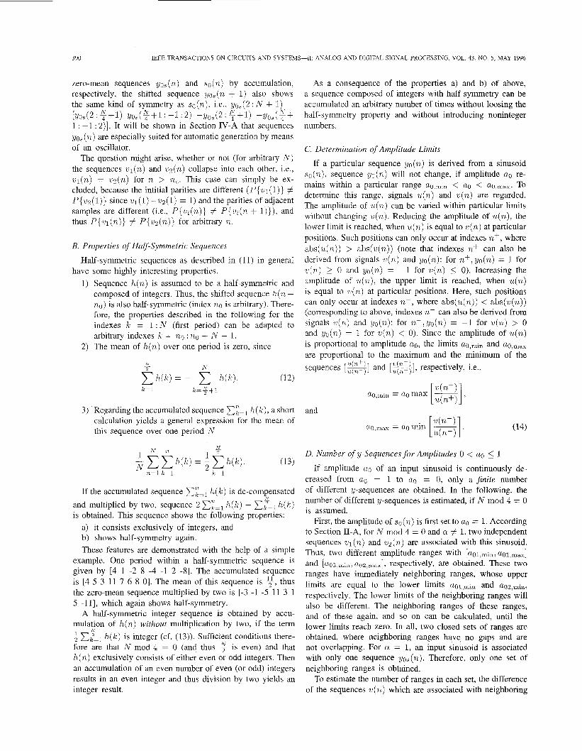
Fig. 3. (a) Block diagram of a digital oscillator incorporating a E-A modulator. (b) Double-integration network (LDIz ). (c) Single-loop E-A modulator
is obtained, when the sequence w(a) derived from an input sinusoid with a0 = E is accumulated. In this case, U(.) is an alternating sequence . . . , 0 1 0 l . . . if U(.) > 0, and . . . , 0 -1 0 -1 0 . . . if U(.) < 0. The resulting amplitude of the accumulated sequence is 6. Assuming a constant decrease A for neighboring ranges, an overall number of i((g)2 - f ) z i(&)' neighboring ranges is obtained, resulting in approximately ;(E)' and ranges for a # 1 and N = 1, respectively.
111. ANALYSIS OF A c-a OSCILLATOR
Section I1 demonstrates that a sinusoid in general is as- sociated with exactly two y-sequences, if U(.) is assumed to be a zero-mean sequence (cf. (5)). For N mod 4 = 0, these y-sequences are independent of each other and show half-symmetry, respectively. It has been shown that integer half-symmetric sequences can be accumulated such that again half-symmetric sequences consisting of integers are obtained. It has also been shown that y-sequences can be insensitive to slight variations of the input sinusoid. These variations in general might be caused by some noise added to the sinusoid, or may simply be variations of the amplitude of the sinusoid (cf. (14)).
In the light of these considerations it seems reasonable to construct an oscillator which automatically generates half- symmetric y-sequences identical to those produced by the driven E A modulator. In the following, only half-symmetric y-sequences are considered, and for convenience, index i = 1 , 2 is omitted.
A. Principle of Operation A block diagram of a E A oscillator is shown in Fig. 3(a).
It consists of a cascade of pairs of lossless discrete integration
392 IEEE TRANSACTIONS ON CIRCUITS AND SYSTEMS-11: ANALOG AND DIGITAL SIGNAL PROCESSING, VOL. 43, NO. 5, MAY 1996
_ - - - - - _ - - - _ - - _ _ _ _ _ -
Fig. 4. (a)
I
LDI,
#1
#R
(b)
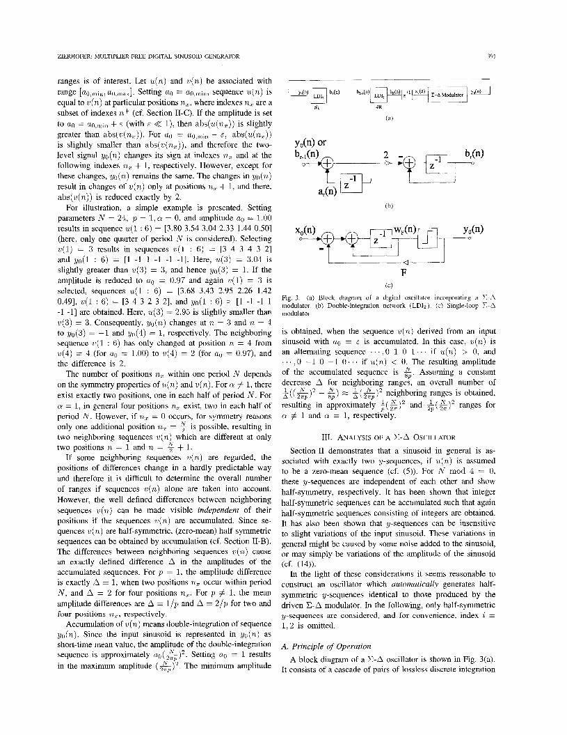
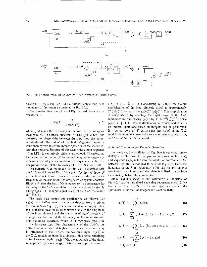
Resonator circuit cut off after the E-A comparator. (b) Modified circuit.
networks (LDI2’s, Fig. 3(b)) and a numeric single-loop E A modulator of first-order as depicted in Fig. 3(c).
The transfer function of an LDIz derived from its z- transform is
where f denotes the frequency normalized to the sampling frequency f s . The phase spectrum of LDIz(f) is zero and therefore no phase shift between the input and the output is introduced. The output of the first integration circuit is multiplied by two to ensure integer operation of the second in- tegration network. Because of this factor, the output sequence of an LDT2 is exclusively either even or odd. Therefore, no factor two at the output of the second integration network is necessary for integer accumulation of sequences in the first integration circuit of the following LDI2 (cf. Section 11-B).
The numeric X-A modulator of Fig. 3(c) is identical with the X-A modulator of Fig. l(a), except for the multiplier F in the feedback branch. Since F determines the oscillation frequency of the oscillator, it is designated as system constant. Block z+l after the last LDI2 is necessary to compensate for the delay in the E A modulator. It can be realized by simply taking b ~ ( n + 1) as input signal ~ ( n ) of the E-A modulator
The basic idea behind this oscillator is as follows. Let yo(n) be a half-symmetric sequence derived from a driven X-A modulator Fig. l(a) for a sinusoidal input so(n). Then the short-time mean of yo(n) is proportional to the amplitude of the input sinusoid and the spectrum of yo(n) consists of a single spectral line at the frequency of the input sinusoid plus the noise spectrum, which is of high-pass type. Due to the low-pass type filter characteristic of the LDT2’s, the noise floor is reduced at higher frequencies. Since no delay is introduced in the LDIz’s, the resulting signal zo(n) at the .CA modulator input is a sinusoid plus some remaining noise. However, within each LDIz, the amplitude of the signal is amplified by about 2(&j2 (this is an approximation of
(cf. Fig. 4).
(15) for f = 5 << 1). Considering R LDIz’s, the overall amplification of the input sinusoid so (n ) is approximately 2 R ( & ) 2 R , i.e., xo(n) M s 0 ( n ) 2 ~ ( X ) ~ ~ . ZTP This amplification is compensated by adapting the input range of the E-A modulator by multiplying yo(n) by F M 2R(&)2R. Since yo(n) E {-I, I}, this multiplication is trivial, and if F is an integer, operations based on integers can be performed. If a system constant F exists such that xo(n) at the %A modulator input is converted into the sequence yo(n) again, self-oscillation can be achieved.
B. Initial Conditions for Periodic Operation
For analysis, the oscillator of Fig. 3(a) is cut open imme- diately after the discrete comparator as shown in Fig. 4(a), and sequence yo (n) is fed into the input. Far convenience, the network Fig. 4(a) is modified to network Fig. 4(b). Here, the integrator of the X-A modulator in Fig. 2(a) is split up into two integration circuits, and the adder is shifted to a position immediately before the comparator.
Since sequence yo(n) is half-symmetric, all registers of Fig. 4(b) can be initialized such that sequences a,(n), b,(n) (for T = 1 ; 2 . . . . . R ) , u ~ ( n ) and U(.) are again half- symmetric composed of integers (cf. Section TI-B)
N 2 -
b , . ( l ) = ~ u , , ( k + I ) , f o r r = 1 , 2 , . . . , R , (17) k = l
N - l 2 2
u ~ ( 1 ) = -- c b ~ ( k + l), and k=l
ZIERHOFER: MULTIPLIER-FREE DIGITAL SINUSOID GENERATOR 393
Note that these initial conditions can be detfermined without system constant F . After determination of F (cf. Section III- C), the initial condition W F (1) can be calculated by W F (1) = U&) - Fw(1).
C. Constraints for System Constant F for Periodic Operation If the output sequence y & ( n ) in Fig. 4(b) is q u a l to the input
sequence yo (n) , the loop can be closed, and operation as au- tonomous oscillator can be achieved. As shown above, the ini- tial conditions for the registers can exclusively be derived from sequence yo (n) . It has also been demonstrated above that con- stant F is approximately F M aR( G ) 2 R , but unfortunately, simple rounding operations like F = floor1[2~( &)2R) , or F = ~ e i l ( 2 ~ ( &)2R) in general yield scaling factors F , which do not result in yb(n) = yo(n).
A convenient approach for finding adequate values of F is made possible with the help of Fig. 4(b). Here, the signal u ~ ( n ) is directly compared with signal F*v(n) . Both signals U F (n) and w (n) are derived from the same input signal yo (n) . Signal ~ ( n ) is obtained by accumulating ?/o(n). The time waveform obtained after multiplying the result by F is rather rough since two neighboring values differ by :tF, respectively. Signal U F (n) is considerably smoother since it is the result of 2R + 1 integrations which eliminate a great deal more of the high-frequency E A noise. Signal y&(n) is simply
yb(n) = sign(uF(n) - F*v(n ) ) . (21)
For general sequences yo(n) with half-symmetry at the input of the network Fig. 4(b) and initial conditions from (16)-(20), yA(n) will differ from yo(n) . However, if yo(n) is E A sequence derived from a pure sinusoid, possibly a real region with upper and lower limits Fmin and F,,,, respectively, can be found, and all real numbers F within Fmlin < F < F,,, yield yb(n) = yo(n).
The limits Pmin and F,,, can be found as the maximum and minimum of the sequences [ -1 and [ -1, respec- tively, where indexes n- and n+ are defined by sequences U(.) and yo(n) as shown in Section II-C
Note that real regions [F,;, , F,,,] (with Fmin < F,,,) are of particular importance for the oscillator implementation, if they contain at least one integer. However, this must not necessarily be the case (cf. Section IV-A, Table I).
D. Hardware Cost As far as R LDI2’s are concerned, the oscillator can be im-
plemented using 2R+1 registers and 2R+2 adders. The length of the registers can be determined by estimating the amplitudes of the signals a l ( n ) , u2(n ) , . . . , U R ( ~ ) , h~(n),bz(n),..., b ~ ( n ) , and w ~ ( n ) , if sequence yo(n) is derived from a sinusoid with amplitude a. = 1. With T = 1,2, . . . , R, these
amplitudes are approximately
max[u,(n)] M 2T-1 ( & y - l ,
and
The resulting register lengths (including the sign-bit) are
and
The maximum register length is L,. For example, for N = 213 = 8192 and p = 1, L, = 24 b for R = 1, and L, = 46 b for R = 2. Each doubling of period N increases the length of L, by 2R b.
IV. SIMULATION RESULTS
A. Generability of y-Sequences This section investigates whether a sequence yo(n) derived
from a sinusoid so(n) can be generated by means of the autonomous E A oscillator. Some general conclusions can be drawn regarding at the DFT-spectra Yo(m) and So(m). The DFT of sequence so(n) here is defined as
So(m) as the DFT of a sinusoid shows two spectral lines at m = p + 1 and m = N + 1 - p and is zero elsewhere. The spectrum Yo(m) in general can be written as
Yo(m) = So(m) exp -j-(m - I) + r (m) (26)
where the first term is the spectrum of so(n) delayed by one unit, and the second term is the noise spectrum r(m) as a consequence of the quantization noise. Since yo(n) is zero-mean, the dc-component Yo(l) = 0 in any case. In the resonator loop, signal yo(n) is filtered by a chain of LDI2’s to remove the influence of r(m) and to enhance the component at m = p+ 1 (here and in the following only indexes 1 5 m 5 are considered). However, the noise spectrum r(m) in general is not zero at m = p + 1, and its influence on the phase of Yo(p + 1) in principle cannot be removed by the LDI2’s (cf. the zero-delay transfer-function (15)).
For p # 1, spectrum Yo(m) in general has components within 1 < m < p + 1, and due to the filter-function of the LDI2 ’s, these components are amplified even more strongly than the spectral line at m = p + 1. Therefore, with respect
( : 1
394 IEEE TRANSACTIONS ON CIRCUITS AND SYSTEMS-11: ANALOG AND DIGITAL SIGNAL PROCESSING, VOL. 43, NO. 5 , MAY 1996
TABLE I GENERABILITY OF SEQUENCES
to the generability of a y-sequence, the case p = 1 clearly has to be preferred.
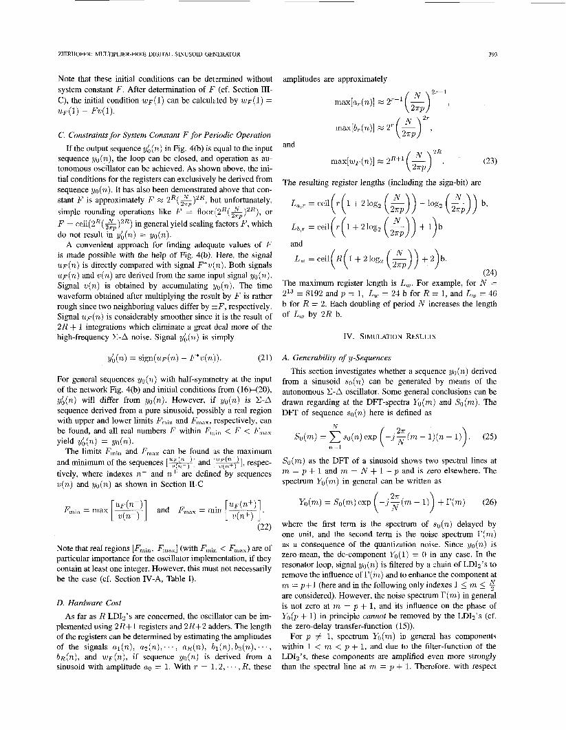
As shown in Section II-A, special symmetry properties occur setting cr = 1. In this case, sequence yos(n) is associated Fig. 5. Regions [Fmin, Fmax] for an oscillator with one
p = 1, and a = 1. Each single horizontal solid line corresponds to one output sequence yos(n + 1) have the same kind of symmetry. region [Fmin, Fma,l,
Setting p = 1, it follows for the spectral line at m = 2 that
Regions Emin, F,&
with the input sinusoid, and the input sinusoid and the shifted LDI2(R = 1): y-sequences are derived from sinusoids with h’ = 256 ,
i.e., the phase of the input sinusoid exactly coincides with the phase of the first harmonic of sequence yos(n), except for one unit delay. This fact has an important impact on the generability of sequences yos(n) (with p = 1). It means that in principle each sequence yos (n ) can be generated by means of the oscillator, provided a sufficient reduction of the noise spectrum of Yos(m) by the chain of LDI2’s. Equation (27) in general is not fulfilled for arguments arg(Yo(2)) for arbitrary phase factors cr and p = 1, and therefore additional filtering with LDI2’s will not necessarily improve the generability of the sequences yo (n) .
Some results are summarized in Table I. Columns 1-3 contain the parameters N , a, and p defining the sinusoid so(n) . The overall number of y-sequences is calculated in column 4, if the amplitude is reduced from a0 = 1 to a0 = 0. Depending on the number R of LDI2’s (column 5), a particular number of y-sequences can be generated by means of the oscillator. Column 6 shows the number of y-sequences with F,,, < F < F,,,, and column 7 yields the number of regions [F,,,, Fmax] which contain at least one integer.
For sinusoids defined by N = 256, p = 1, and U: = 1, in all 826 different sequences yos(n) are obtained. For an oscillator containing one LDI2(R = l), 815 sequences yield regions with Fmin < F < F,,,, and out of these, 797 regions contain at least one F as an integer. For 11 regions, Fmln > F,,,, and these results correspond to y-sequences, which cannot be generated by the oscillator with one LDI2. For R = 2, 824 y- sequences can be generated with operations on integers. Here, additional filtering helps to increase the number of sequences that can be produced by the oscillator.
If all possible y-sequences are derived for N = 256, p = 1, and cr = 0, 1631 different y-sequences are obtained. For R = 1, 1095 sequences yield regions with F,,, < F < Fmax. Out of these, 1048 regions contain at least one F as an integer. For R = 2, 1009 regions with F,,, < F < F,, are obtained,
and each of these contains at least one integer. Here the number of sequences that can be generated by the oscillator even decreases, when two LDIz’s are used instead of one. This clearly underlines the importance of (27) and the exceptional importance of sequences yos (n) in the present application.
Table I also depicts some results for p = 3. As expected, the number of y-sequences that can be generated by the oscillator is comparatively low. Corresponding to the considerations stated above, the number of possible sequences is significantly reduced for R = 2 instead of R = 1.
For illustration, all regions [Fmin, F,,] with F,in < Fmax derived from input sinusoids with N = 256 ,p = 1, and a = 1 are depicted in Fig. 5 and show a structure similar to a fir tree. The location of the tree is at F M M 3320. In Fig. 5, each region [F,;,, F,,,] is represented by a horizontal solid line.
It might be of practical interest to search for y-sequences for a given amplitude a0 and varying period N , which can be generated by the oscillator. However, the number of different y-sequences increases approximately proportional to N 2 , and thus the mean width of the regions [a~,,i~,u~,,,~] over one period is proportional to &. Therefore, if the original sequence yo(n) cannot be generated, it might be sufficiently accurate to take the next possible sequence y i (n ) , whose corresponding region [a:,,;,, is closest to the original region.
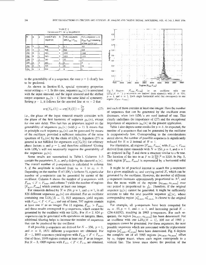
For example, all y-sequences have been computed for a0 = .95,p = 1, and cr = 1, and increasing period N = (256:4:8192), resulting in 1985 y-sequences. For each se- quence, the region [ q m i n , a ~ , ~ ~ ~ ] has been determined. For an oscillator with one LDIz(El = 1), 106 out of 1985 y- sequences cannot be generated. For these sequences, the next possible sequences which are associated with the replacement regions a{,max] have been determined. Fig. 6 depicts the complete set of all 1985 regions [ u o , ~ ~ , , u ~ , ~ ~ ~ ] offset by a0 (upper trace), where each region corresponds to a vertical line. The lower trace shows the position of the
ZIERHOFER: MULTIPLIER-FREE DIGITAL SINUSOID GENERATOR 395
-5
x 10"
-
9 0 ~
2000 3000 4000 5000 6wO 7000 8000 9000 Period N
5t 1 O t
Fig. 6. Upper trace: All regions [ a ~ , ~ i ~ , u o , ~ ~ ~ ] offset by ao = 0.95 and N = (256 : 4 : 8192), Lower trace: Replacement regiam [a:,min, a:,max] offset by a0 for y-sequences which can be generated by an oscillator with R = 1. Each region is associated with a vertical line.
106 replacement regions [a:,min, a~,,,,]. Fig. 6 also contains functions k(g)-2 representing the mean width 2(g)-2 of the regions [ u ~ , ~ i ~ , a ~ , ~ ~ , ] for period N , when a! = 1 and p = 1 (cf. Section 11-D). Fig. 6 demonstrates that the regions are situated close to or even within the functions Az($ ) -~ , so that the error resulting from taking thern instead of the original region is marginal.
If an oscillator with two LDI2's is considered, there are only 3 y-sequences which cannot be generated for a. = 0.95, a = 1 , p = 1, and N = (256:4:8192).
B. Signal-to-Noise Ratio
The spectral properties of two-level E A sequences in general have been broadly discussed in literature, e.g., [6]. In [7], especially E A systems of first-order with sinusoidal input signals are investigated.
In the present application, the Signal-to-Noise ratio within a given signal band f c can be exactly computed, since for N mod 4 = 0, both sequences so (n ) and y / ~ ( n ) are periodic with period N . The overall noise spectrum is given by
The number of spectral lines m, within the signal band [O, fc] is
m, = ceil f c - = ceil -- ( I) (2&) (29)
where OSR is the oversampling ratio. Thus the noise power within [-fc,fc] is
2o t I
0 0.1 0.2 0.3 0.4 0.5 0.6 0.7 0.8 0.9 1 101
Amplitude
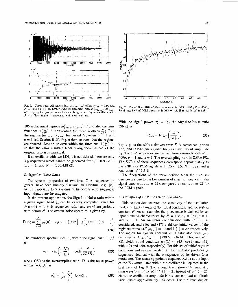
Fig. 7. Solid line: SNR of PCM-signals with OSR = 1.5, B =11.5 b ( N = 128).
Dotted line: SNR of S A sequences for OSR =I92 (iV = 4096),
With the signal power cr: = 9, the Signal-to-Noise ratio (SNR) is
SNR= lolog(&).
Fig. 7 plots the SNR's derived from E-A sequences (dotted line) and PCM-signals (solid line) as functions of amplitude ao. The E-A sequences are derived from sinusoids with N = 4096, p = 1 and a = 1. The oversampling ratio is OSR=192. The SNR's of these sequences correspond approximately to the SNR's of PCM-signals with OSR=1.5, N = 128, and a resolution of 11.5 b.
The fluctuations of the curve derived from the S A se- quences are due to the low number of spectral lines within the signal band (mc,c-a = l l ) , compared to m c , p c ~ = 43 for the PCM-signals.
C. Examples of Unstable Oscillation Modes
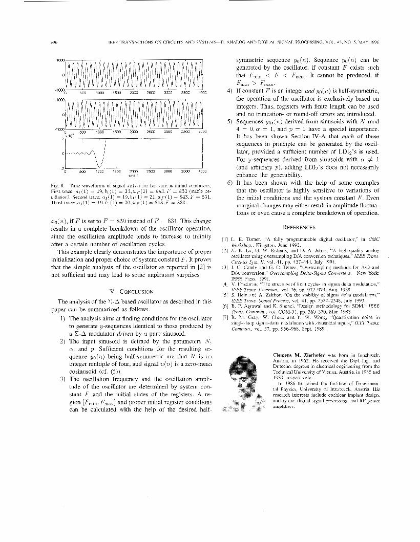
This section demonstrates the sensitivity of the oscillation modes to slight changes of the initial conditions and the system constant F . As an example, the y-sequence is derived for an input sinusoid characterized by N = 128, a0 = 0 . 9 8 , ~ = 1, and a! = 1. An oscillator configuration with R = 1 is considered, and (16) and (17) yield the initial values of the registers of the LDI 2a1 (1) = 19 and bl (I) = 20, respectively. The region for system constant F is calculated with (22) resulting in [F,i,, F,,,] = [830.60, 836.441. Choosing F = 831 yields initial condition w ~ ( 1 ) = 843 ( u ~ ( 1 ) and w ( 1 ) with (19) and (20), respectively). For this set of initial register conditions and system constant F , the oscillator produces y- sequences identical with the y-sequences of the driven E A modulator. The resulting periodic sequence zo(n) at the input of the E-A-modulator within the oscillator is depicted in the first trace of Fig. 8. The second trace shows the simulated time waveform of ~ ( n ) if b l ( 1 ) = 21 instead of b l ( 1 ) = 20. Here, the oscillation amplitude is not constant and amplitude variations of approximately 10% occur. The third trace depicts
396 IEEE TRANSACTIONS ON CIRCUITS AND SYSTEMS-11: ANALOG AND DIGITAL SIGNAL PROCESSING, VOL. 43, NO. 5 , MAY 1996
0
0 500 1000 1500 2000 2500 3000 3500 4000 -1 000
1000
0
-1000 0 500 1000 1500 2000 2500 3000 3500 4000
lo4
0 Y 1
0 500 1000 1500 2000 2500 3000 3500 4000 -2 ’
time n
Fig. 8. Time waveforms of signal xc(n) for for various initial conditions, First trace: al(1) = 1 9 , b l ( l ) = 2 0 , w p ( l ) = 843.F = 831 (stable os- cillation). Second trace: a l ( 1 ) = 1 9 , b l ( l ) = 2 1 . ~ ~ ( 1 ) = S43.F = 831. Third trace: al(1) = 1 9 , b l ( l ) = 2 0 , u , ~ ( 1 ) = 813.F = 830.
rco(n), if F is set to F = 830 instead of F = 831. This change results in a complete breakdown of the oscillator operation, since the oscillation amplitude tends to increase to infinity after a certain number of oscillation cycles.
This example clearly demonstrates the importance of proper initialization and proper choice of system constant F . It proves that the simple analysis of the oscillator as reported in [2] is not sufficient and may lead to some unpleasant surprises.
V. CONCLUSION
The analysis of the E-A based oscillator as described in this
1) The analysis aims at finding conditions for the oscillator to generate y-sequences identical to those produced by a E A modulator driven by a pure sinusoid.
2) The input sinusoid is defined by the parameters N . a , and p . Sufficient conditions for the resulting se- quence yo(n) being half-symmetric are that N is an integer multiple of four, and signal U(.) is a zero-mean cosinusoid (cf. (5)).
3) The oscillation frequency and the oscillation ampli- tude of the oscillator are determined by system con- stant F and the initial states of the registers. A re- gion [F’,, , F,,,] and proper initial register conditions can be calculated with the help of the desired half-
paper can be summarized as follows.
symmetric sequence yo(n). Sequence yo(n) can be generated by the oscillator, if constant F exists such that F,,,, < F < F,,,. It cannot be produced, if
4) If constant F is an integer and y o ( n ) is half-symmetric, the operation of the oscillator is exclusively based on integers. Thus, registers with finite length can be used and no truncation- or round-off errors are introduced.
5) Sequences yos(.) derived from sinusoids with N mod 4 = 0. Q = 1, and p = 1 have a special importance. It has been shown Section IV-A that each of these sequences in principle can be generated by the oscil- lator, provided a sufficient number of LDI2’s is used. For y-sequences derived from sinusoids with a # 1 (and arbitrary p), adding LDIz’s does not necessarily enhance the generability.
6) It has been shown with the help of some examples that the oscillator is highly sensitive to variations of the initial conditions and the system constant F . Even marginal changes may either result in amplitude fluctua- tions or even cause a complete breakdown of operation.
F m m > F m a x .
REFERENCES
[ I ] L. E. Turner, “A fully programmable digital oscillator,” in CMC Workshop.. Kingston, June 1992.
[2] A. K. Lu; G. W. Roberts, and D. A. Johns, “A high-quality analog oscillator using oversampling D/A conversion techniques,” IEEE Trans. Circuits Spr . ZZ, vol. 41, pp. 437444 , July 1994.
131 J. C. Candy and G. C. Temes, “Oversampling methods for AD and DIA conversion,“ Oversampling Delta-Sigma Converters. New York: IEEE Press, 1991.
[4] V. Friedman, “The structure of limit cycles in sigma-delta modulation,”
[5] S. Hein and A. Zakhor, “On the stability of sigma delta modulators,” IEEE Trans. Signal Process, vol. 41, pp. 2322-2348, July 1993.
[6] B. P. Agrawal and K. Shenoi, “Design methodology for SDM,” IEEE Trans. Commun., vol. COM-31, pp. 360-370, Mar. 1983.
[7] R. M. Gray, W. Chou, and P. W. Wong, “Quantization noise in single-loop sigma-delta modulation with sinusoidal inputs,” IEEE Trans. Cominun., vol. 37, pp. 956-968, Sept. 1989.
IEEE Trails. Commun.. vol. 36, pp. 972-979, Aug. 1988.
Clemens M. Zierhofer was born in Innsbruck, Austria, in 1962. He received the DipLIng. and Dr.techn. degrees in electrical engineering from the Technical University of Vienna, Austria, in 1985 and 1989, respectively.
In 1986 he joined the Institute of Experimen- tal Physics, University of Innsbruck, Austria. His research interests include cochlear implant design, analog and digital signal processing, and RF-power amplifiers.