Embed Size (px)
Citation preview

Astoria Generating Company , LP
18-01 20th Avenue
Long Island City NY 11105-4271
X
Gowanus Generating Station
29th St & Second Avenue
Brooklyn 11232
X X
General Electric LMS100 Combustion Turbine
Baranello, Mark (718) 499-6368
0 0 1 0 0 0 46 100 162 774 105.85 909,052 885.8 X
03 885.8 Gas 839.2 Oil 1
69
LMSOC Express Integrated Technologies or Equivalent – Oxidation Catalyst 6-2010
52
06 2010
98
Janet Bernardo 16 078701(781)431 -1151
LMS100 Power Block 1
XX
Figure 1 Site Locus, Figure 2 Site Plan, Figure 3 LMS100
1 General Electric LMS100 885 885
51 1 General Electric LMS100 32 839 839
LMSCR 98 Express Integrated Technologies or Equivalent – Selective Catalytic Reduction 6-2010
24 365
24 365
X 3
786 103.56 889,453 839.216210046000100
Gas
Oil
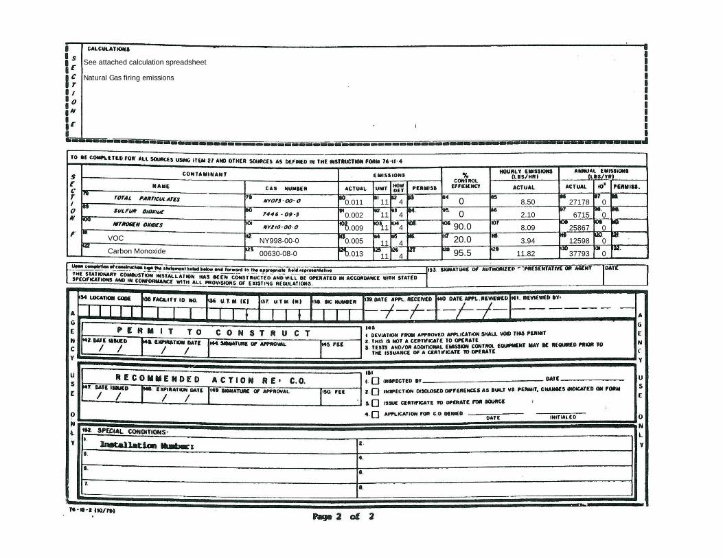
VOC
Carbon MonoxideNY998-00-0
00630-08-0
11
11
11
11
11
4
4
4
4
4 27178
6715
25867
12598
37793
0
0
0
0
0
See attached calculation spreadsheet
00
90.020.095.5
0.011
0.002
0.009
0.005
0.013
8.50
2.10
8.09
3.94
11.82
Natural Gas firing emissions

VOC
Carbon MonoxideNY998-00-0
00630-08-0
11
11
11
11
11
4
4
4
4
4 22733
1017
9004
3824
9398
0
0
0
0
0
See attached calculation spreadsheet
0
0
91.7
37.5
96.0
0.0344
0.0015
0.0136
0.0058
0.0142
28.83
1.29
11.42
4.85
11.92
X3 X 3
Lead 007439-92-1 0.000014 11 4 0 0.012 9.5 0
ULSD firing emissions

NYC DEP Emissions CalculationsSummary Sheet
LMS100 Emission Analysis - Summary Sheets
Pollutant LMS100 PTETons Per Year
NOx 13.94CO 21.23SO2 3.36NO2 (as NOx) 13.94PM 19.26PM10 19.26PM2.5 19.26VOC 6.32Pb 0.005NH3 11.03
2009 ESS Group, Inc. 2/20/2009

LMS100 PTE
Potential LMS100 Capacity Factor (CF) and Allowable Emissions
Gas Oil Gas Oil Gas Oil2,452.80 613.2 0.00 788.4 3,197.4 0
Gas fired (lbs/hr)
Oil fired (lbs/hr)
Start Up PTE/Yr (Tons)
Shut Down PTE/Yr (Tons)
LMS100 Natural Gas Emissions
TPY
LMS100 ULSD
Emissions TPY
LMS100 Potential To Emit
TPY
LMS100 Natural Gas Emissions
TPY
LMS100 ULSD
Emissions TPY
LMS100 Potential To Emit
TPY
LMS100 Natural Gas Emissions
TPY
LMS100 ULSD
Emissions TPY
LMS100 Potential To Emit
TPYNOx 8.09 11.42 0.20 0.31 10.44 3.50 13.94 0.51 4.50 5.02 13.45 0.00 13.45CO 11.82 11.92 0.99 1.35 16.83 3.65 20.49 2.34 4.70 7.04 21.23 0.00 21.23SO2 2.10 1.29 2.58 0.40 2.97 0.00 0.51 0.51 3.36 0.00 3.36PM10/PM2.5 8.50 28.83 10.42 8.84 19.26 0.00 11.37 11.37 13.59 0.00 13.59VOC 3.94 4.85 4.83 1.49 6.32 0.00 1.91 1.91 6.30 0.00 6.30Pb 0.00 0.012 0.00 0.004 0.004 0.00 0.005 0.005 0.00 0.00 0.000NH3 5.98 12.06 7.33 3.70 11.03 0.00 4.75 4.75 9.56 0.00 9.56Note: The shaded emissions above represents the potential-to-emit (PTE) in tons per year (TPY) for the LMS100
LMS100 PTE Emission SummaryPollutant LMS100 PTE
Tons per YearNOx 13.94CO 21.23SO2 3.36PM10/PM2.5 19.26VOC 6.32Pb 0.005NH3 11.03
LMS100 36.5% NG CFHours per YearHours per Year
LMS100 35% Annual CF LMS100 9% Oil CFHours per Year
2009 ESS Group, Inc. 2/20/2009
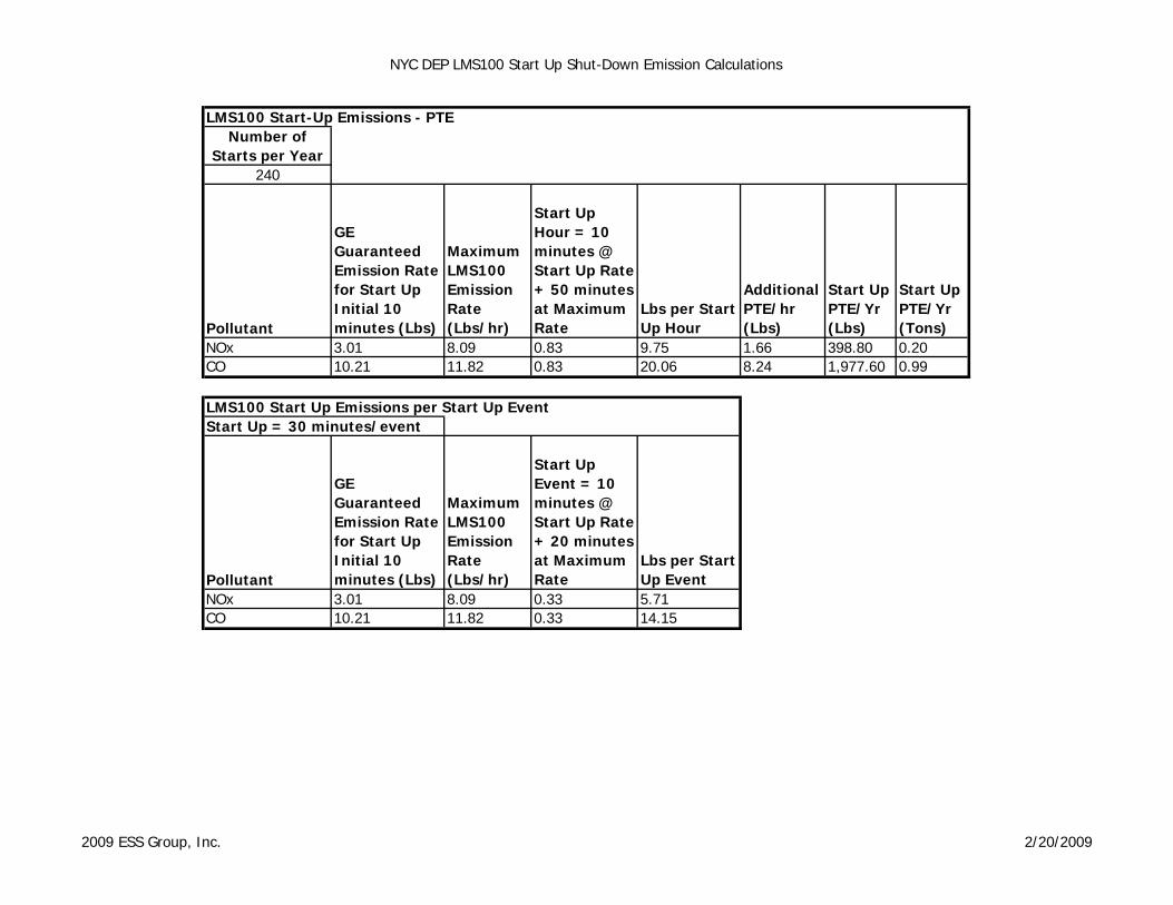
NYC DEP LMS100 Start Up Shut-Down Emission Calculations
LMS100 Start-Up Emissions - PTE
240
Pollutant
GE Guaranteed Emission Rate for Start Up Initial 10 minutes (Lbs)
Maximum LMS100 Emission Rate (Lbs/hr)
Start Up Hour = 10 minutes @ Start Up Rate + 50 minutes at Maximum Rate
Lbs per Start Up Hour
Additional PTE/hr (Lbs)
Start Up PTE/Yr (Lbs)
Start Up PTE/Yr (Tons)
NOx 3.01 8.09 0.83 9.75 1.66 398.80 0.20CO 10.21 11.82 0.83 20.06 8.24 1,977.60 0.99
LMS100 Start Up Emissions per Start Up Event Start Up = 30 minutes/event
Pollutant
GE Guaranteed Emission Rate for Start Up Initial 10 minutes (Lbs)
Maximum LMS100 Emission Rate (Lbs/hr)
Start Up Event = 10 minutes @ Start Up Rate + 20 minutes at Maximum Rate
Lbs per Start Up Event
NOx 3.01 8.09 0.33 5.71CO 10.21 11.82 0.33 14.15
Number of Starts per Year
2009 ESS Group, Inc. 2/20/2009

NYC DEP LMS100 Start Up Shut-Down Emission Calculations
LMS100 Shut-Down Emissions - PTE
240
Pollutant
GE Guaranteed Emission Rate for Shut Down Final 10 Minutes (Lbs)
Maximum LMS100 Emission Rate (Lbs/hr)
Shut Down Hour = 10 minutes @ Shut Down Rate + 50 minutes @ Maximum Rate
Lbs per Shut Down Hour
Additional PTE/hr (Lbs)
Shut Down PTE/Yr (Lbs)
Shut Down PTE/Yr (Tons)
NOx 3.97 8.09 0.83 10.71 2.62 629.20 0.31CO 13.21 11.82 0.83 23.06 11.24 2,697.60 1.35
LMS100 Shut Down Emissions per Shut Down Event Shut Down = 30 minutes/event
Pollutant
GE Guaranteed Emission Rate for Shut Down Final 10 minutes (Lbs)
Maximum LMS100 Emission Rate (Lbs/hr)
Shut Down Event = 10 minutes @ Shut Down Rate + 20 minutes at Maximum Rate
Lbs per Shut Down Event
NOx 3.97 8.09 0.33 6.67CO 13.21 11.82 0.33 17.15
Number of Starts per Year
2009 ESS Group, Inc. 2/20/2009

GE LMS100 NG Emission Rates
Operation 3,197.40 hrs/yrStack Base Elevation 4.00 ft mslStack Base Elevation 1.22 m mslStack Height 100.00 feetStack Height 30.48 metersStack Diameter 13.50 feetStack Diameter 4.11 metersExhaust Area 143.14 sq feetReference Temp 68.00 oFCase Number 300 203 303 301 204 304 302 205 305Load (%) 100 100 100 75 75 75 50 50 50Ambient Temp (oF) -5 59 105 -5 59 105 -5 59 105Air+Gas Flow (lb/hr) 1,732,698 1,699,142 1,465,993 1,463,575 1,456,181 1,253,267 1,162,871 1,155,972 999,715Air+Gas Flow mol wt 28.12 28.05 27.92 28.23 28.15 28.05 28.35 28.24 28.16Exhaust Flow (scfm) 395,492 388,830 336,986 332,754 332,008 286,778 263,263 262,765 227,856Exhaust Flow (acfm) 889,507 909,052 818,089 750,933 763,964 693,096 602,841 613,438 560,757Exit Velocity (ft/sec) 103.572 105.847 95.256 87.436 88.954 80.702 70.193 71.427 65.293Exit Velocity (m/sec) 31.569 32.262 29.034 26.651 27.113 24.598 21.395 21.771 19.901Exhaust Temp (oF) 727.5 774.4 821.8 731.5 755.0 816.1 749.1 772.6 839.4Exhaust Temp (K) 659.6 685.6 711.9 661.8 674.8 708.8 671.5 684.6 721.7
NOx 7.75 8.09 6.88 6.16 6.34 5.49 4.56 4.66 4.11CO 11.32 11.82 10.05 8.99 9.26 8.01 6.65 6.81 6.00PM10/PM2.5 7.78 8.43 8.46 7.60 7.88 8.04 7.48 7.69 7.81NH3 5.73 5.98 5.09 4.55 4.68 4.05 3.37 3.45 3.03S from Turbine 1.05 0.82 0.61SO2 1.91 2.10 1.70 1.51 1.64 1.35 1.11 1.21 1.01VOC 3.94 3.59 3.02 3.32 3.06 1.86 2.56 1.90 1.14PbH2SO4 0.05 0.05 0.05 0.05 0.05 0.05 0.05 0.05 0.05
MMBtu/hr, LHV 787.7 805.3 700.5 623.9 631.3 556.6 453.5 464.8 415.3MMBtu/hr, HHV 866.5 885.8 770.6 686.3 694.4 612.3 498.9 511.3 456.8
NOx 0.00895 0.00913 0.00893 0.00897 0.00913 0.00896 0.00913 0.00912 0.00899CO 0.01307 0.01334 0.01305 0.01311 0.01333 0.01309 0.01334 0.01333 0.01313PM10/PM2.5 0.00898 0.00952 0.01098 0.01107 0.01134 0.01313 0.01499 0.01504 0.01710NH3 0.00661 0.00675 0.00660 0.00663 0.00675 0.00662 0.00675 0.00674 0.00664S from Turbine 0.00118 0.00118 0.00118SO2 0.00220 0.00237 0.00220 0.00220 0.00237 0.00220 0.00223 0.00237 0.00220VOC 0.00455 0.00405 0.00392 0.00483 0.00441 0.00304 0.00513 0.00372 0.00249PbH2SO4 0.00006 0.00006 0.00006 0.00007 0.00007 0.00008 0.00010 0.00010 0.00011
Notes:1. All emission rates provided by General Electric2. Natural Gas = (1.1) LHV = HHV3. Natural Gas Maximum Fuel Sulfur Content = 0.85 grains of Sulfur per 100 SCF
Copyright © ESS Group, Inc., 2009
Emissions (lb/hr)
Fuel Flow
lb/MMBtu, HHV
SPIP - Gowanus Generating StationNatural Gas Firing
GE LMS100 Emission Inputs & Emission Rates - AQ PermittingESS Job № U160-000
2009 ESS Group, Inc. 2/20/2009

GE LMS100 ULSD Emission Rates
Operation 788.40 hrs/yrStack Base Elevation 4.00 ft mslStack Base Elevation 1.22 m mslStack Height 100.00 feetStack Height 30.48 metersStack Diameter 13.50 feetStack Diameter 4.11 metersExhaust Area 143.14 sq feetReference Temp 68.00 oFCase Number 100B 103 103B 101B 104 104B 102B 105 105BLoad (%) 100 100 100 75 75 75 50 50 50Ambient Temp (oF) -5 59 105 -5 59 105 -5 59 105Air+Gas Flow (lb/hr) 1,735,367 1,677,347 1,421,523 1,465,832 1,435,489 1,211,705 1,164,578 1,138,054 983,166Air+Gas Flow mol wt 28.65 28.56 28.52 28.70 28.62 28.56 28.75 28.67 28.61Exhaust Flow (scfm) 388,733 376,913 319,962 327,828 321,914 272,314 260,005 254,777 220,588Exhaust Flow (acfm) 888,103 889,453 786,060 750,325 748,120 669,148 603,017 601,053 547,317Exit Velocity (ft/sec) 103.408 103.565 91.527 87.366 87.109 77.914 70.214 69.985 63.728Exit Velocity (m/sec) 31.519 31.567 27.897 26.629 26.551 23.748 21.401 21.331 19.424Exhaust Temp (oF) 746.3 786.0 837.2 748.5 767.1 837.4 764.6 785.6 850.1Exhaust Temp (K) 670.0 692.0 720.5 671.2 681.5 720.6 680.1 691.8 727.6
NOx 11.28 11.42 9.55 8.93 8.95 7.62 6.58 6.60 5.70CO 11.77 11.92 9.96 9.32 9.34 7.95 6.86 6.89 5.95PM10/PM2.5 28.59 28.83 24.71 22.73 22.62 19.79 16.92 16.85 14.92NH3 11.91 12.06 10.08 9.43 9.45 8.05 6.94 6.97 6.02S from Turbine 0.65 0.51 0.37SO2 1.28 1.29 1.08 1.01 1.01 0.86 0.74 0.75 0.64VOC 4.85 4.70 3.99 4.09 4.01 3.39 3.24 3.18 2.75Pb 0.01 0.01 0.01 0.01 0.01 0.01 0.01 0.01 0.01H2SO4 0.02 0.02 0.02 0.02 0.02 0.02 0.02 0.02 0.02
MMBtu/hr, LHV 794.6 791.7 671.6 629.2 621.2 536.3 463.4 457.9 401.3MMBtu/hr, HHV 842.3 839.2 711.9 667.0 658.5 568.5 491.2 485.4 425.4
NOx 0.01340 0.01361 0.01341 0.01339 0.01360 0.01340 0.01339 0.01360 0.01340CO 0.01398 0.01420 0.01399 0.01397 0.01419 0.01399 0.01397 0.01419 0.01398PM10/PM2.5 0.03394 0.03436 0.03471 0.03408 0.03436 0.03481 0.03445 0.03472 0.03507NH3 0.01414 0.01437 0.01416 0.01414 0.01436 0.01415 0.01414 0.01436 0.01415S from Turbine 0.00077 0.00077 0.00077SO2 0.00152 0.00154 0.00152 0.00151 0.00154 0.00151 0.00151 0.00154 0.00150VOC 0.00575 0.00560 0.00560 0.00613 0.00609 0.00597 0.00660 0.00654 0.00646Pb 0.00001 0.00001 0.00001 0.00001 0.00002 0.00002 0.00002 0.00002 0.00002H2SO4 0.00002 0.00002 0.00003 0.00003 0.00003 0.00004 0.00004 0.00004 0.00005
Notes:1. All emission rates provided by General Electric2. Maximum Liquid Fuel Sulfur Content = 0.0015% S by weight3. Liquid Fuel = (1.06) LHV = HHV
Copyright © ESS Group, Inc., 2009
Emissions (lb/hr)
Fuel Flow
lb/MMBtu, HHV
SPIP - Gowanus Generating StationULSD Firing
GE LMS100 Emission Inputs & Emission Rates - AQ PermittingESS Job № U160-000
2009 ESS Group, Inc. 2/20/2009

Gowanus Generating Station, 29th St. & Second Avenue Brooklyn
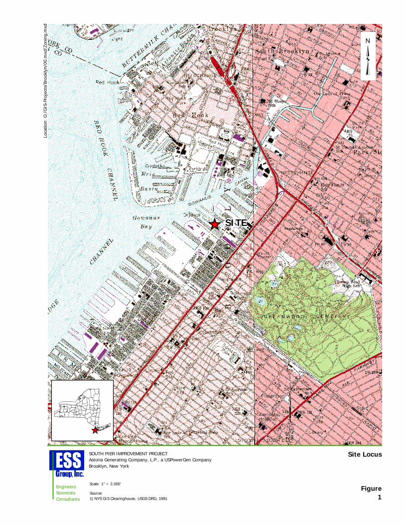
Figure1
Site Locus
Loca
tion:
G:/
GIS
-Pro
ject
s/B
rook
lyn/
00.m
xd/Z
onin
g.m
xd
EngineersScientistsConsultants
SOUTH PIER IMPROVEMENT PROJECTAstoria Generating Company, L.P., a USPowerGen CompanyBrooklyn, New York
Source:1) NYS GIS Clearinghouse, USGS DRG, 1981
Scale: 1" = 2,000'
SITE


GE Power Systems2707 North Loop WestHouston, TX 77008Telephone 1-713-803-0900
www.gepower.com
GEA13640 (3M, 11/03)
CF6-80C2 and CF6-80E1 are trademarks of GE Aircraft Engines, General Electric Co. LMS100 and MS6001 are trademarks of GE Power Systems, General Electric Co.
Copyright 2003, General Electric Co. All rights reserved.
GE’s New Gas Turbine System: Designed to Change the Game in Power Generation
The Tradition of Excellence Continues …
™

ANew
Beginning
GE Aircraft Engines Technology
GE Power SystemsTechnology
New High Efficiency Gas TurbineFor the Power Generation Industry
LM MSLMS
GE's NewGas TurbinePowerGenerationSystem
The LMS100™ is the first intercooled gas turbine system developed especially for the power generation industry, utilizing the best of two technologies --- heavy-duty frame gas turbine and aeroderivative gas turbine technology. The LMS100 will deliver 100MW at 46% thermal efficiency. This efficiency is 10 % higher than GE's highest simple cycle efficiency gas turbine available today. It is specifically designed for cyclic applications providing flexible power for peaking, mid-range and baseload.
The compressed air from the Low Pressure Compressor (LPC) is cooled in either an air-to-air or air-to-water heat exchanger (intercooler) and ducted to the High Pressure Compressor (HPC). The cooled flow means less work for the HPC, increased overall efficiency and power output. The cooler LPC exit temperature air, used for turbine cooling, allows higher firing temperatures, resulting in increased power output and overall efficiency.
Only GE Can Bring You the Best of Both WorldsThe LMS100 features a heavy-duty low pressure compressor derived from GE Power Systems’ MS6001FA heavy-duty gas turbine compressor; its core which includes the high pressure compressor, combustor and high pressure turbine is derived from GE Aircraft Engines’ CF6-80C2® and CF6–80E1® aircraft engines. The design of the new 2-stage intermediate pressure turbine and new 5-stage power turbine is based on the latest aeroderivative gas turbine technology. The exhaust and aft shaft for hot-end drive are designed using heavy-duty gas turbine practices.
Inlet Collector
To
Intercooler
LPC
Exhaust Collector
Aeroderivative
Supercore
From
Intercooler
Flexible Power: High Efficiency High Part-Power Efficiency, 50% Power......39% High Simple Cycle Efficiency…………......46% High STIG Efficiency……………………....50% High Combined Cycle Efficiency……….....54%
Intercooler
LPCHPC
Combustor
HPTIPT
PT
Output Shaft
Only GE has the Imagination and Ability to Combine the… Best of Both Worlds.

LMS100Addressing
IndustryNeeds
LMS100ProductFeatures
The Right Solution. Rugged Design With Proven Components.
When asked to describe their requirements for future power generation facilities, customers identified the following items as high on their priority list:
100 MW blocks of power
High efficiency at full and part-power
Cycling capability
Fast start
Peaking capability
Sustained hot-day power
Fuel flexibility
Low emissions
All agreed that a new gas turbine which met theserequirements would be an important addition to their generation mix.
The LMS100 has been designed to specificallyaddress all of these needs, changing the game inthe power generating industry.
The LMS100 is the Right Solution: Outstanding full- and part-power efficiency
Low hot-day lapse rate
High availability – aero modular maintenance
Low maintenance cost
Designed for cycling applications No cost penalty for starts and stops Load-following capability
10 Minutes to full power Improves average efficiency in cycling Potential for spinning reserve credits Reduced start-up emissions
Synchronous condenser capability
The LMS100 features an inlet and an LPC comprised of the first six stages of the MS6001FA compressor. These stages are followed by an aerodynamically designed volute which ducts the low pressure compressed air into the intercooler. This LPC provides high airflow capacity for the LMS100 Gas Turbine System.
Industrial
of a Finned Tube
Cooled air from the intercooler is ducted back through another aerodynamically designed volute into the aero supercore. The high efficiency aeroderivative supercore consists of: a high pressure compressor (HPC) based on the CF6-80C2 strengthened fof the LMS100
a combustoannular combulow emissions a high presthe CF6-80E1 a 2-stage indesigned to drand flexible c
Following the coupled powespecifically forand aft drive sgas turbine ex
Over 600 Advanced F
aircraft engine compressor,
Industrial Example
of a Tube & Shell Heat Exchanger
Example
Heat Exchanger
or the high (42:1) pressure ratio ; r which can be either a standard stor (SAC) or an advanced dry
(DLE2) combustor;sure turbine (HPT) derived from aircraft engine;termediate pressure turbine (IPT) ive the LPC through a mid-shaft oupling.
IPT is a 5-stage aerodynamically r turbine (PT) that has been designed the LMS100. The exhaust frame haft are based on a rugged heavy-duty haust design.
Technology Units WithNearly 8 Million Fired Hours
3,786 CF6-80 Engines in OperationWith More Than 103 Million Operating Hours
The LPC air is ducted to an air-to-air orair-to-water heat exchanger where it is cooled before being ducted to the HPC. Both designs are industry standard heat exchangers with significant operating hours in multiple industries and are designed to the API 660 and TEMA C standards.

Designed for Availability and Maintainability.
LMS 100Gas
TurbineProduct
Description
To Intercooler
LM Aero Supercore
Low Pressure Compressor (LPC)
LPC Exit& DiffuserDuct toIntercooler
High Pressure Collector & DuctFrom Intercooler
Radial Inlet
Maintainability Features
Modular construction permits replacement of the aero components without total disassembly. Multiple borescope ports allow on-condition monitoring without turbine disassembly. Condition based maintenance and
remote diagnostics.
Split casing construction of the LPC and aeroderivative compressor allows detailed on-site inspection and blade replacement. Hot-section field maintenance can be done in several days. Accessories are externally mounted for ease of on-site replacement.
2-StageIntermediatePressure Turbine(Drives LPC)
5-Stage Power Turbine
Hot End Drive ShaftCoupling
DiffuserTurbine RearFrameStandard Annular
Combustor
High Pressure Compressor
Rotable “Supercore” Enhances Power Plant AvailabilityGE has established a target availability of 97.5% for a mature GE-built LMS100 power plant. Its power plant target reliability is 98.5%. The rotable “supercore” consists of the HPC, Combustor, HPT and IPT modules.
LMS100 Service IntervalsThe expected service intervals for the LMS100 based upon normal operation include: On-site hot-section replacement………………………….25,000 fired hours* Depot maintenance; overhaul of hot section and inspection of all systems, power turbine overhaul …50,000 fired hours* Next on-site hot section replacement ……………………75,000 fired hours* Depot maintenance……………………………………….100,000 fired hours*
*Note: These are actual fired hours; no multipliers for cycling are needed.
Rotable modules can be installed duringon-site maintenance. A lease or spare “supercore”and a power turbine module can be installed in 24 hours when depot maintenance is required.
Maintenance ServicesAll warranty and follow-on services for the LMS100will be provided by GE Power Systems on-site or at its several depot locations around the world. These services can include ContractualService Agreements, Lease Engines, Spare Parts,Rotable Modules, Training and Training Tools.
2-StageHigh Pressure Turbine

PackageDesign
LMS100PlantSystemDesign
Reliability Designed In . Configured To Meet Your Needs.
AuxiliariesSkid
Inlet
VBV Stack and Silencer
Air-to-AirIntercooler
Exhaust StackGenerator
Bellows ExpansionJoints
The LMS100 gas turbine package system was designed for reliable operation, easy access for maintenance and quick installation. The auxiliarysystems are pre-assembled on a single skid and factory tested prior to shipment. The auxiliary skid is mounted in front of the turbine base plateutilizing short flexible connectors reducing mechanical interconnects by 25%. The complete gas turbine driver package can be shipped by truck.
LMS100 Plant System DesignWhile the actual plant layout will besite dependent, it will contain basic elementswhich include an inlet, an auxiliaries skid containing a water wash system, lube oil system and starter system, a turbine skid, an intercooling system, a generator, silencers, exhaust system and acontrol system.
Air-to-Air IntercoolerIn locations where water is scarce or very expensive, the basic LMS100 power plant will contain a highly reliable air-to-air intercooler. This unit will be a tube and fin style heat exchanger in an A-frame configuration which is the same as typical steam condensing units in general conformance with API 661 standards. Similar units are in service in the Oil and Gas industry today. In high ambient temperature climates, an evaporative cooling system can be added for power augmentation. This system would use a small amount of water for short time periods as required.
Air-to-Water IntercoolerIn locations where water is readily abundant or less expensive the intercooler can be of the air-to-water type also found in many industrial applications. The intercooler would be a tube and shell type heat exchanger.
Either type of intercooler will be connected through a system of piping and expansion bellows, from the low pressure compressor volute to the intercooler and upon return to the high pressure compressor inlet volute.
Control SystemSignificant emphasis has been placed on controls design for increased reliability of the entire power plant. The LMS100 control system will have dual channel architecture with a cross-channel data link providing redundancy which will allow multiple failures without engine shutdown. A fiberoptic distributed I/O system located outside the module will be unaffected by electromagnetic or radio frequency interference which will eliminate noisy wiring. Site intercon-nects are reduced by 90% compared to the typical gas turbine control system.
FuelsThe LMS100 SAC will be equipped with dual fuel capability so that it can burn either natural gas or distillate fuels. The LMS100 DLE will operate ongas fuel.
Emissions ControlThe LMS100 gas turbine system has all the advantages of an aeroderivative gas turbine inachieving low emissions. The LMS100 gas turbine with the SAC combustor (using water or steam for NOx control) and the advanced DLEcombustor (DLE2) are designed to achieve 25 ppm NOx. This represents a 7 to 18% reduction in mass emissions rate (lbs/kwh) vs. the LM6000. In locations where less than 25 ppm NOx is required a low temperature SCR can be used. The high efficiency of the LMS100 results in exhaust temperatures below 800ºF (427ºC) which permits the use of low temperature SCRs without tempering air.
Noise ControlThe gas turbine-generator will be rated at 85 dBA average at 3 feet (1 meter). An option for 80 dBA at 3 feet will be available.
GeneratorThe generator is dual rated for 50 or 60 Hz applications. Either an air-cooled or TWAC configuration can be provided.
LMS100 is Available in a Variety of ConfigurationsFour basic LMS100 configurations are available as this product is introduced. When combined with intercooler selection and duty applications, the LMS100 will offer the customer 20 different configuration choices.
LMS100 SYSTEM CONFIGURATIONSProduct Offerings CombustorFuel Power
Augmentation
LMS100 SAC, 50/60 Hz
Gas, Liquid or Dual Fuel
Single Annular (SAC)
Single Annular (SAC)
Water None 25 ppm
25 ppm
25 ppm
25 ppm
LMS100 SACSTIG, 50/60 Hz
Gas
Gas
Steam
Steam
None None
NoneLMS100 SAC Steam, 50/60 Hz
Steam Injection
LMS100 DLE, 50/60 Hz
DLE2
Moisture Separator
AuxiliariesSkid
Inlet
VBV Stack and Silencer
Air-to-AirIntercooler
Exhaust StackGenerator
Bellows ExpansionJoints
Gas Single Annular (SAC)
Wind Wall
Air-to-AirFinned TubeHeat Exchanger
CoolingTower
Air-to-WaterTube and ShellHeat Exchanger
Diluent NOx Level

LMS100Applications
For Power
Generation
Competitive Over A Wide Output Range.
LMS100 Provides Outstanding Customer Value in 80+ MW Applications
The attributes of the LMS100 make it a versatile power generation system offering customers increased operational flexibility in a wide variety of applications:
Simple Cycle / Peaking & Mid-Range…high efficiency, low first cost, sustained hot day power, 10-minute starts and no maintenance penalty for cycling, yield the ideal peaking solution. Throw in high part-power efficiency and load following capability to get high dispatch capability for mid-range applications.
STIG …steam injection for power augmentation provides significant efficiency and power improvements, as well as flexibility. With variable STIG, an operator can inject all of the steam into the gas turbine or pass the steam to process to take advantage of electricity prices or process steam value.
Combined Cycle …the low exhaust temperature leads to lower cost exhaust system materials, smaller steam turbines, condensers and generators, leading to a lower steam plant installed cost.
Another benefit from the lower exhaust temperature is more power from duct firing (up to 30MW).
Combined Heat & Power …the high power-to-steam ratio allows the LMS100 to meet the steam demand served by 40-50MW gas turbines while delivering more than twice the power. Using both exhaust and air-to-water intercooler energy, an LMS100 plant can reach >85% thermal efficiency.
50Hz and 60Hz Applications …the LMS100 can operate at 50Hz and 60Hz operation without a gearbox, reducing system complexity, plot size and cost, while increasing reliability.
Off-Frequency Operation …the LMS100 will operate with very little power variation for up to 5% reduction in grid frequency, allowing grid support in times of high demand and load fluctuations.
When your power generation need exceeds 100MW, the LMS100 can provide an economic solution in a multi-unit arrangement by providing high efficiency power with unmatched flexibility.

LMS100 ISO Performance Data
Conditions: Performance at the generator terminals
NOx = 25 ppm
59ºF, 60% Relative Humidity
Losses: 0”/0” inlet/exhaust
Fuel: Spec. Gas (LHV = 19000 BTU/lb)
Simple Cycle Gas Turbine 60Hz Applications
ISO
Per
form
ance
Dat
a
Model Output Heat Rate Efficiency (MWe) (BTU/KWH) %
DLE 98.7 7509 46
SAC (w/Steam) 102.1 7167 48
SAC (w/Water) 102.6 7813 44
STIG 112.2 6845 50
AuxiliariesSkid
Air Inlet(Loss Included)
VBV Silencer
Cooling Tower
Exhaust Stack(Loss Not Included)
Generator (Performance at Generator Terminals)
Turbine Skid
Air-to-Water Intercooler(Pressure LossIncluded)
Air Inlet(Loss Not Included)
Simple Cycle Gas Turbine 50Hz Applications
GEA13640-1 (11/03)
Model Output Heat Rate Efficiency (MWe) (KJ/KWH) %
DLE 99 7921 45
SAC (w/Steam) 102.2 7603 47
SAC (w/Water) 102.5 8247 44
STIG 110.8 7263 50
Conditions: Performance at the generator terminals
NOx = 25 ppm
15ºC, 60% Relative Humidity
Losses: 0mm/0mm inlet/exhaust
Fuel: Spec Gas (LHV = 44.2MJ/KG)
AuxiliariesSkid
VBV Silencer
Cooling Tower
Exhaust Stack(Loss Not Included)
Generator (Performance at Generator Terminals)
Air-to-Water Intercooler(Pressure LossIncluded)
Air Inlet(Loss Not Included)
LMS100 ISO Performance Data