Embed Size (px)
Citation preview

OWNERS MANUALMODEL #425
KRENDL MACHINE COMPANY • 1201 SPENCERVILLE RDDELPHOS, OHIO 45833 • TELEPHONE 800-459-2069 • FAX 419-695-9301
E - MAIL: [email protected] • WEB SITE: www.krendlmachine.com
60 YEARS OF AMERICAN INGENUITY

CONGRATULATIONS ON YOUR PURCHASE OF KRENDL EQUIPMENT
MODEL #425OWNER'S MANUAL
FOR ASSURED SAFETY AND CONFIDENCE, PLEASE READ THISMANUAL CAREFULLY BEFORE INSTALLING AND OPERATINGYOUR MACHINE.
E-MAIL ADDRESS IS: [email protected] SITE IS: www.krendlmachine.com
INTRODUCTION. . . . . . . . . . . . . . . . . . . . . . . . . . . . . . . . .
GENERAL SAFETY INFORMATION. . . . . . . . . . . . . . . . . .
DECALS . . . . . . . . . . . . . . . . . . . . . . . . . . . . . . . . . . . . . .
WARRANTY . . . . . . . . . . . . . . . . . . . . . . . . . . . . . . . . . . . .
RETURNED GOODS PROCEDURE and SPECIFICATIONS
BASIC COMPONENTS. . . . . . . . . . . . . . . . . . . . . . . . . . . .
OPERATING INSTRUCTIONS . . . . . . . . . . . . . . . . . . . . . .
GENERAL MAINTENANCE . . . . . . . . . . . . . . . . . . . . . . . . .
TROUBLESHOOTING . . . . . . . . . . . . . . . . . . . . . . . . . . . .
ELECTRICAL . . . . . . . . . . . . . . . . . . . . . . . . . . . . . . . . . . .
LADDER DIAGRAM . . . . . . . . . . . . . . . . . . . . . . . . . . . . . .
PARTS LIST . . . . . . . . . . . . . . . . . . . . . . . . . . . . . . . . . . . .
GLOSSARY . . . . . . . . . . . . . . . . . . . . . . . . . . . . . . . . . . . .
SERVICE RECORD. . . . . . . . . . . . . . . . . . . . . . . . . . . . . .
PAGE1
2-3
4-5
6
7
8
9-10
11-13
14
15-19
20-23
24-27
28
29
Table of Contents
Rev. Date: 7/7/20 Page 1
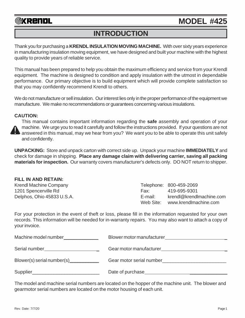
MODEL #425INTRODUCTION
Thank you for purchasing a KRENDL INSULATION MOVING MACHINE. With over sixty years experiencein manufacturing insulation moving equipment, we have designed and built your machine with the highestquality to provide years of reliable service.
This manual has been prepared to help you obtain the maximum efficiency and service from your Krendlequipment. The machine is designed to condition and apply insulation with the utmost in dependableperformance. Our primary objective is to build equipment which will provide complete satisfaction sothat you may confidently recommend Krendl to others.
We do not manufacture or sell insulation. Our interest lies only in the proper performance of the equipment wemanufacture. We make no recommendations or guarantees concerning various insulations.
CAUTION:This manual contains important information regarding the safe assembly and operation of yourmachine. We urge you to read it carefully and follow the instructions provided. If your questions are notanswered in this manual, may we hear from you? We want you to be able to operate this unit safelyand confidently.
UNPACKING: Store and unpack carton with correct side up. Unpack your machine IMMEDIATELY andcheck for damage in shipping. Place any damage claim with delivering carrier, saving all packingmaterials for inspection. Our warranty covers manufacturer's defects only. DO NOT return to shipper.
FILL IN AND RETAIN:Krendl Machine Company Telephone: 800-459-20691201 Spencerville Rd Fax: 419-695-9301Delphos, Ohio 45833 U.S.A. E-mail: [email protected]
Web Site: www.krendlmachine.com
For your protection in the event of theft or loss, please fill in the information requested for your ownrecords. This information will be needed for in-warranty repairs. You may also want to attach a copy ofyour invoice.
Machine model number_____________ Blower motor manufacturer _
Serial number _ Gear motor manufacturer _
Blower(s) serial number(s)___________ Gear motor serial number________________________
Supplier_________________________ Date of purchase ______________
The model and machine serial numbers are located on the hopper of the machine unit. The blower andgearmotor serial numbers are located on the motor housing of each unit.
Rev. Date: 7/7/20 Page 2
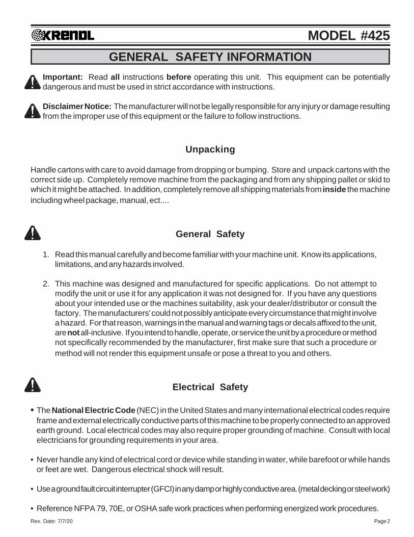
MODEL #425GENERAL SAFETY INFORMATION
Important: Read all instructions before operating this unit. This equipment can be potentiallydangerous and must be used in strict accordance with instructions.
Disclaimer Notice: The manufacturer will not be legally responsible for any injury or damage resultingfrom the improper use of this equipment or the failure to follow instructions.
Unpacking
Handle cartons with care to avoid damage from dropping or bumping. Store and unpack cartons with thecorrect side up. Completely remove machine from the packaging and from any shipping pallet or skid towhich it might be attached. In addition, completely remove all shipping materials from inside the machineincluding wheel package, manual, ect....
General Safety
1. Read this manual carefully and become familiar with your machine unit. Know its applications,limitations, and any hazards involved.
2. This machine was designed and manufactured for specific applications. Do not attempt tomodify the unit or use it for any application it was not designed for. If you have any questionsabout your intended use or the machines suitability, ask your dealer/distributor or consult thefactory. The manufacturers' could not possibly anticipate every circumstance that might involvea hazard. For that reason, warnings in the manual and warning tags or decals affixed to the unit,are not all-inclusive. If you intend to handle, operate, or service the unit by a procedure or methodnot specifically recommended by the manufacturer, first make sure that such a procedure ormethod will not render this equipment unsafe or pose a threat to you and others.
Electrical Safety
• The National Electric Code (NEC) in the United States and many international electrical codes requireframe and external electrically conductive parts of this machine to be properly connected to an approvedearth ground. Local electrical codes may also require proper grounding of machine. Consult with localelectricians for grounding requirements in your area.
• Never handle any kind of electrical cord or device while standing in water, while barefoot or while handsor feet are wet. Dangerous electrical shock will result.
• Use a ground fault circuit interrupter (GFCI) in any damp or highly conductive area. (metal decking or steel work)
• Reference NFPA 79, 70E, or OSHA safe work practices when performing energized work procedures.
Rev. Date: 7/7/20 Page 3
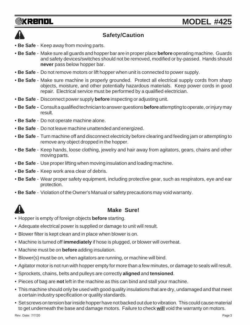
MODEL #425Safety/Caution
• Be Safe - Keep away from moving parts.• Be Safe - Make sure all guards and hopper bar are in proper place before operating machine. Guards
and safety devices/switches should not be removed, modified or by-passed. Hands shouldnever pass below hopper bar.
• Be Safe - Do not remove motors or lift hopper when unit is connected to power supply.• Be Safe - Make sure machine is properly grounded. Protect all electrical supply cords from sharp
objects, moisture, and other potentially hazardous materials. Keep power cords in goodrepair. Electrical service must be performed by a qualified electrician.
• Be Safe - Disconnect power supply before inspecting or adjusting unit.• Be Safe - Consult a qualified technician to answer questions before attempting to operate, or injury may
result.• Be Safe - Do not operate machine alone.• Be Safe - Do not leave machine unattended and energized.• Be Safe - Turn machine off and disconnect electricity before clearing and feeding jam or attempting to
remove any object dropped in the hopper.• Be Safe - Keep hands, loose clothing, jewelry and hair away from agitators, gears, chains and other
moving parts.• Be Safe - Use proper lifting when moving insulation and loading machine.• Be Safe - Keep work area clear of debris.• Be Safe - Wear proper safety equipment, including protective gear, such as respirators, eye and ear
protection.• Be Safe - Violation of the Owner's Manual or safety precautions may void warranty.
Make Sure!• Hopper is empty of foreign objects before starting.• Adequate electrical power is supplied or damage to unit will result.• Blower filter is kept clean and in place when blower is on.• Machine is turned off immediately if hose is plugged, or blower will overheat.• Machine must be on before adding insulation.• Blower(s) must be on, when agitators are running, or machine will bind.• Agitator motor is not run with hopper empty for more than a few minutes, or damage to seals will result.• Sprockets, chains, belts and pulleys are correctly aligned and tensioned.• Pieces of bag are not left in the machine as this can bind and stall your machine.• This machine should only be used with good quality insulations that are dry, undamaged and that meet
a certain industry specification or quality standards.• Set screws on tension bar inside hopper have not backed out due to vibration. This could cause material
to get underneath the base and damage motors. Failure to check will void the warranty on motors.
Rev. Date: 7/7/20 Page 4
MODEL #425DECALS
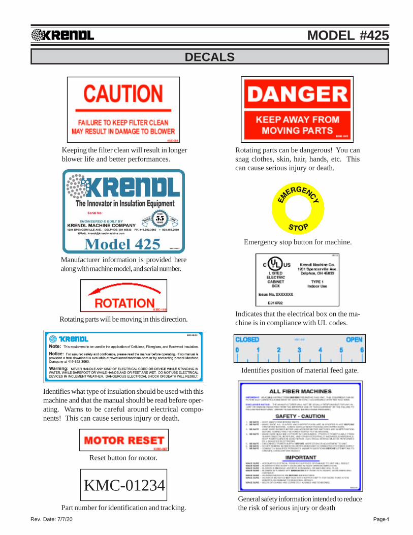
Rotating parts can be dangerous! You cansnag clothes, skin, hair, hands, etc. Thiscan cause serious injury or death.
Manufacturer information is provided herealong with machine model, and serial number.
Keeping the filter clean will result in longerblower life and better performances.
General safety information intended to reducethe risk of serious injury or death
Reset button for motor.
Rotating parts will be moving in this direction.
KMC-01234Part number for identification and tracking.
Indicates that the electrical box on the ma-chine is in compliance with UL codes.
Emergency stop button for machine.
Identifies position of material feed gate.
Identifies what type of insulation should be used with thismachine and that the manual should be read before oper-ating. Warns to be careful around electrical compo-nents! This can cause serious injury or death.
Rev. Date: 7/7/20 Page 5
MODEL #425
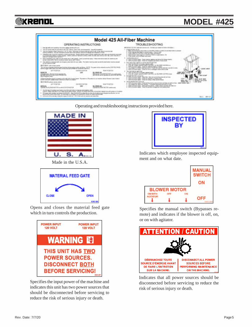
Opens and closes the material feed gatewhich in turn controls the production.
Made in the U.S.A.
Indicates which employee inspected equip-ment and on what date.
Indicates that all power sources should bedisconnected before servicing to reduce therisk of serious injury or death.
Operating and troubleshooting instructions provided here.
Specifies the manual switch (Bypasses re-mote) and indicates if the blower is off, on,or on with agitator.
Specifies the input power of the machine andindicates this unit has two power sources thatshould be disconnected before servicing toreduce the risk of serious injury or death.
Rev. Date: 7/7/20 Page 6
MODEL #425WARRANTY:
Krendl Machine Company (Company) warrants to each original purchaser (Buyer) of itsmachines that such products will be free of manufacturing defects for a period of 2 years fromthe date of shipment to the Buyer. (This does not include accessories, pumps, blowers, wallscrubbers, etc.)
No warranty is made with respect to:
1. Components or accessories manufactured and warranted by others. Warranties forpurchased component parts as supplied from vendor such as engine, electric motor,blower, gearbox, transmission, etc., if furnished by the manufacturer of the component, areon file at the Company’s main office and copies will be furnished at request of Buyer.Component(s), shipping costs prepaid, shall be sent to Company who in turn shall forwardto vendor for evaluation and warranty determination.
2. Any defect caused by repair, alteration and/or adjustment performed by Buyer or customer/vendor of Buyer without the express written authorization of the Company.
3. The labor costs of replacing parts by parties other than the Company.4. Any machine that has not been operated and/or maintained in accordance with normal
industry practice and the written recommendations of the Company. (e.g. machine oper-ated with an improperly sized, worn or damaged hose, improper or inattention to preven-
maintenance, etc.)5. The product has been subjected to misuse, negligence or accident or results of any
application or use of the blowing equipment not in accordance with the Company recom-mendations.
This limited warranty does not cover the free replacement of component parts that becomeinoperative due to wear and usage and need to be replaced on a regular basis, including but notlimited to: airlock seal(s), agitator(s), shredder(s), auger(s), fuse(s), switch(es), clutch(es), hose(s),shaft seal(s), chain(s), belt(s), sprocket(s), pulley(s), bearing(s), cable(s), battery(ies), filter(s),fan(s), etc.
The Company’s obligation under this warranty is limited to repairing or replacing (at Companyoption) any part that is determined by the Company to be suffering from a manufacturing defect.The Company (at Company option) will provide any required parts and labor to the Buyer. If theequipment or parts must be returned to the Company for repair, all transportation costs shall bethe Buyer’s responsibility.
THIS LIMITED WARRANTY IS EXPRESSLY IN LIEU OF ANY OTHER GUARANTEES AND / ORWARRANTIES, ORAL OR WRITTEN, EXPRESSED OR IMPLIED, INCLUDING WITHOUT LIMITA-TION, THE IMPLIED WARRANTY OF MERCHANTABILITY. NO WARRANTY, EXPRESS ORIMPLIED, OTHER THAN THE AFORESAID WARRANTY IS MADE OR AUTHORIZED BY COM-PANY. COMPANY SHALL NOT BE LIABLE FOR ANY DIRECT, INDIRECT, INCIDENTAL ORCONSEQUENTIAL DAMAGES TO PROPERTY OR INJURY TO ANY PERSON OR COSTS ASSO-CIATED WITH LOSS OF PRODUCTION RESULTING IN LOSS OF REVENUE, PROFITS OR LOSSOF EQUIPMENT THROUGH THE USE OF THIS EQUIPMENT.
Note: Special job circumstances incurring costs for specialized repair and next day deliveryof parts will not be reimbursed by the manufacturer unless authorized by factory.
Rev. Date: 7/7/20 Page 7
MODEL #425RETURNED GOODS PROCEDURE:
IF MACHINE WAS NOT PURCHASED DIRECTLY FROM KRENDL MACHINE COMPANY, CONTACTYOUR SUPPLIER / DISTRIBUTOR.
When returning products to Krendl for repair, first obtain a return goods authorization, at which time youwill be given shipping instructions. The product must be shipped PREPAID:
Krendl Machine Company Telephone: 800-459-20691201 Spencerville Rd Fax: 419-695-9301Delphos, Ohio 45833 U.S.A. E-mail: [email protected]
Web Site: www.krendlmachine.com
Once the unit is received, it will be inspected. In-warranty units will be repaired and returnedimmediately. An estimate of repair charges will be provided for out-of-warranty units.
SPECIFICATIONSMODEL#: 425 (Single Input) 425 (Double Input)
HEIGHT: 44" 44"WIDTH (DEPTH): 25" 25"LENGTH: 36" 36"WEIGHT: 220 pounds 220 poundsELECTRICAL: 120VAC, 15 amp, S.I. 120VAC, 15 amp, D.I.BLOWER VOLUME: 104 CFM 140 CFMBLOWER PRESSURE: 2.0 PSI maximum 4.5 PSI maximumHOSE OUTPUT: 2.5” diameter 2.5" diameter
MAXIMUM FEED RATES:CELLULOSE: 1400 lbs./hr.FIBERGLASS: 480 lbs./hr.MINERAL FIBER: 800 lbs./hr.
WARNING: Recommended hose size, type and length must be used to achieve maximum results. Krendlcannot guarantee performance of the machine if hoses are undersized, worn, damaged, orhoses other than those we recommend are used.
BEFORE YOU RUN THIS MACHINE...PLEASE READ THE REST OF THIS MANUAL!!
Rev. Date: 7/7/20 Page 8
MODEL #425
I G
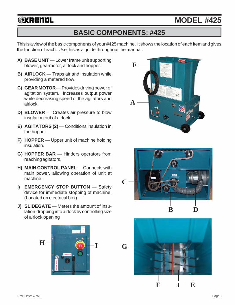
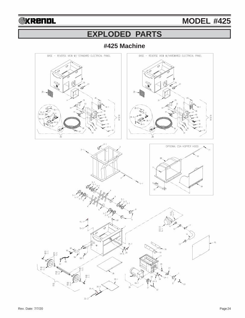
BASIC COMPONENTS: #425This is a view of the basic components of your #425 machine. It shows the location of each item and givesthe function of each. Use this as a guide throughout the manual.
A) BASE UNIT — Lower frame unit supportingblower, gearmotor, airlock and hopper.
B) AIRLOCK — Traps air and insulation whileproviding a metered flow.
C) GEAR MOTOR — Provides driving power ofagitation system. Increases output powerwhile decreasing speed of the agitators andairlock.
D) BLOWER — Creates air pressure to blowinsulation out of airlock.
E) AGITATORS (2) — Conditions insulation inthe hopper.
F) HOPPER — Upper unit of machine holdinginsulation.
G) HOPPER BAR — Hinders operators fromreaching agitators.
H) MAIN CONTROL PANEL — Connects withmain power, allowing operation of unit atmachine.
I) EMERGENCY STOP BUTTON — Safetydevice for immediate stopping of machine.(Located on electrical box)
J) SLIDEGATE — Meters the amount of insu-lation dropping into airlock by controlling sizeof airlock opening
F
A
H
B
C
E
D
J E
Rev. Date: 7/7/20 Page 9
MODEL #425OPERATING INSTRUCTIONS
1. Read all safety and operating instructions before operating this unit.
2. This unit comes ready for connection with hose, clamps, and power cords, and accessories.
3. This unit provides a direct hook-up to 2 1/2" I.D. hose. Slide hose on blower outlet and secure with ahose clamp to provide safe working conditions. All hose connections should have hose clamps toprevent air leakage and separation of hose.
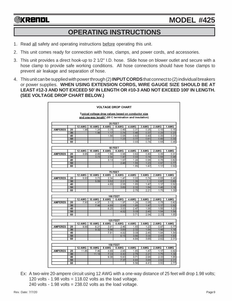
4. This unit can be supplied with power through (2) INPUT CORDS that connect to (2) individual breakersor power supplies. WHEN USING EXTENSION CORDS, WIRE GAUGE SIZE SHOULD BE ATLEAST #12-3 AND NOT EXCEED 50' IN LENGTH OR #10-3 AND NOT EXCEED 100' IN LENGTH.(SEE VOLTAGE DROP CHART BELOW.)
Ex: A two-wire 20-ampere circuit using 12 AWG with a one-way distance of 25 feet will drop 1.98 volts;120 volts - 1.98 volts = 118.02 volts as the load voltage.240 volts - 1.98 volts = 238.02 volts as the load voltage.
Rev. Date: 7/7/20 Page 10
MODEL #425
Operating Instruction (cont.)5. When assembling unit, make sure all controls are in OFF position. Hook up electrical supply. Caution:
Operating unit with less than required voltage, more than required voltage, or inadequate generator sizewill result in damage to electrical components. This machine is marked on the side of the machine withthe correct input voltage required. Note: Agitator motor and blower should only be operated with steadyor constant flow of electricity between 110-120 volts. Do not operate machine with less than or morethan required voltage. Damage to motors and other electrical parts will result, voiding warranty.
Follow instructions below for machines with remote control (SECTION A) or without remote (SECTION B).NOTE: Input cords must be supplied with power from two separate sources for the unit to work properly.
6. This machine is equipped with an emergency stop button for your safety. This button must be pulled outand the start button must be pressed for the machine to start.
7. This machine is equipped with a limit switch that does not allow the machine to run without the hopperattached to the machine. The hopper must be on and tightly secured for machine to operate.
SECTION A (with remote control)This unit has a separate electrical panel that has a three position switch as follows: (NOTE: This panel willbe referred to as the CONTROL PANEL and the toggle switch at the end of the remote cord as theREMOTE CONTROL SWITCH.)
LEFT POSITION CENTER POSITION RIGHT POSITIONREMOTE OFF BLOWER ON
Automatic side of switch whichoperates the BLOWER MOTORon with AGITATOR MOTOR withthe remote control switch. (Mostfrequently used.)
A Manual Operation Switch is located on the right side of control panel. Flip switch to ON position to runmachine without Remote Control Switch. NOTE: Units with variable blower control turn to on position.
LEFT POSITION CENTER POSITION RIGHT POSITIONMANUAL OFF BLOWER ON
Operates the BLOWER MOTORon with AGITATOR MOTOR
8. The first bag of insulation in the hopper should be well broken by hand to assist agitator action.Note: Hopper bars MUST be in place while loading hopper.Caution: NEVER put hands below bars or force-feed material by pushing down on insulation.
9. Fill hopper with insulation and adjust SLIDEGATE. Open SLIDEGATE to allow insulation to drop intothe airlock providing good production, but not beyond point where hose plugs. As hose length isincreased, the SLIDEGATE should be closed proportionally.
10.At the end of the workday, empty the hopper and BLOW OUT THE HOSE with the machine.
SECTION B (without remote control)
Manual side which operates theBLOWER MOTOR continuouslywhile operating the AGITATORMOTOR with remote control switch.
Manual side operates theBLOWER MOTOR continuously.
Rev. Date: 7/7/20 Page 11
MODEL #425GENERAL MAINTENANCE
Periodic preventive maintenance will add years of life to your equipment. Reviewing the information inthis manual will go a long way in reducing downtime. Remove hopper for easy maintenance of lowerbase unit.
KEEP CLEAN: During operation, keep material from accumulating on Blower Filter. Always keep Filterin place while operating machine. After each use, remove insulation from hopper and blow out hose.Caution: Be sure to unplug machine before servicing.
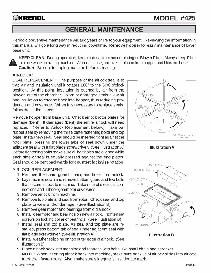
AIRLOCK:SEAL REPLACEMENT: The purpose of the airlock seal is totrap air and insulation until it rotates 180O to the 6:00 o'clockposition. At this point, insulation is pushed by air from theblower, out of the chamber. Worn or damaged seals allow airand insulation to escape back into hopper, thus reducing pro-duction and coverage. When it is necessary to replace seals,follow these directions:
Remove hopper from base unit. Check airlock rotor plates fordamage (bent). If damaged (bent) the entire airlock will needreplaced. (Refer to Airlock Replacement below.) Take outrubber seal by removing the three plate fastening bolts and topplate. Install new seal. Seal should be inserted tight against therotor plate, pressing the lower tabs of seal down under theadjacent seal with a flat blade screwdriver. (See Illustration A)Before tightening bolts make sure all bolt holes are aligned whileeach side of seal is equally pressed against the end plates.Seal should be bent backwards for counterclockwise rotation.
AIRLOCK REPLACEMENT:1. Remove the chain guard, chain, and hose from airlock.2. Lay machine down and remove bottom guard and two bolts
that secure airlock to machine. Take note of electrical con-nections and unhook gearmotor drive wires.
3. Remove airlock from machine.4. Remove top plate and seal from rotor. Check seal and top
plate for wear and/or damage. (See Illustration B)5. Remove gear motor and bearings from old airlock.6. Install gearmotor and bearings on new airlock. Tighten set
screws on locking collar of bearings. (See Illustration B)7. Install seal and top plate. As seal and top plate are in-
stalled, press bottom tab of seal under adjacent seal withflat blade screwdriver. (See Illustration A)
8. Install weather stripping on top outer edge of airlock. (SeeIllustration B)
9. Place airlock back into machine and reattach with bolts. Reinstall chain and sprocket.NOTE: When inserting airlock back into machine, make sure back lip of airlock slides into airlocktrack then fasten bolts. Also, make sure slidegate is in slidegate track.
Illustration A
Illustration B
Rev. Date: 7/7/20 Page 12
MODEL #425General Maintenance (cont.)
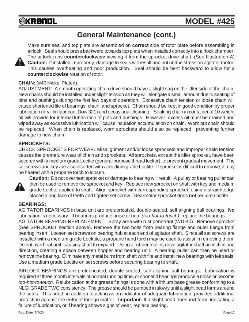
Make sure seal and top plate are assembled on correct side of rotor plate before assembling inairlock. Seal should press backward towards top plate when installed correctly into airlock chamber.The airlock runs counterclockwise viewing it from the sprocket drive shaft. (See Illustration A)Caution: If installed improperly, damage to seals will result and put undue stress on agitator motor.This causes overheating and poor production. Seal should be bent backward to allow for acounterclockwise rotation of rotor.
CHAIN: (#40 Nickel Plated)ADJUSTMENT: A smooth operating chain drive should have a slight sag on the idler side of the chain.New chains should be installed under slight tension as they will elongate a small amount due to seating ofpins and bushings during the first few days of operation. Excessive chain tension or loose chain willcause shortened life of bearings, chain, and sprocket. Chain should be kept in good condition by properlubrication (dry film lubricant Dow 321) and occasional cleaning. Soaking chain in container of 10 weightoil will provide for internal lubrication of pins and bushings. However, excess oil must be drained andwiped away as excessive lubrication will cause insulation accumulation on chain. Worn out chain shouldbe replaced. When chain is replaced, worn sprockets should also be replaced, preventing furtherdamage to new chain.
SPROCKETS:CHECK SPROCKETS FOR WEAR. Misalignment and/or loose sprockets and improper chain tensioncauses the premature wear of chain and sprockets. All sprockets, except the idler sprocket, have beensecured with a medium grade Loctite (general purpose thread locker), to prevent gradual movement. Theset screws and key are also inserted with a medium grade Loctite. If sprocket is difficult to remove, it maybe heated with a propane torch to loosen.
Caution: Do not overheat sprocket or damage to bearing will result. A pulley or bearing puller canthen be used to remove the sprocket and key. Replace new sprocket on shaft with key and mediumgrade Loctite applied to shaft. Align sprocket with corresponding sprocket, using a straightedgeplaced along face of teeth and tighten set screw. Gearmotor sprocket does not require Loctite.
BEARINGS:AGITATOR BEARINGS in base unit are prelubricated, double-sealed, self aligning ball bearings. Nolubrication is necessary. If bearings produce noise or heat (too-hot-to-touch), replace the bearings.AGITATOR BEARING REPLACEMENT: Spray area with rust penetrant (WD-40). Remove sprocket(See SPROCKET section above). Remove the two bolts from bearing flange and outer flange frombearing insert. Loosen set screws on bearing hub at each end of agitator shaft. Since all set screws areinstalled with a medium grade Locktite, a propane hand torch may be used to assist in removing them.Do not overheat unit, causing shaft to expand. Using a rubber mallet, drive agitator shaft an inch in onedirection, creating a space between hopper and bearing unit. A bearing puller can then be used toremove the bearing. Eliminate any metal burrs from shaft with file and install new bearings with felt seals.Use a medium grade Loctite on set screws before securing bearing to shaft.
AIRLOCK BEARINGS are prelubricated, double sealed, self aligning ball bearings. Lubrication isrequired at three month intervals of normal running time, or sooner if bearings produce a noise or becometoo-hot-to-touch. Relubrication at the grease fittings is done with a lithium base grease conforming to aNLGI GRADE TWO consistency. The grease should be pumped in slowly until a slight bead forms aroundthe seals. This bead, in addition to acting as an indicator of adequate lubrication, provides additionalprotection against the entry of foreign matter. Important: If a slight bead does not form, indicating afailure of lubrication, or if bearing shows signs of wear, replace bearing.
Rev. Date: 7/7/20 Page 13
MODEL #425General Maintenance (cont.)
AIRLOCK BEARING REPLACEMENT: Remove two bolts from bearing and follow steps above for agitatorbearing replacement.
GEARMOTOR DRIVE:If drive motor runs hot, or unit does not run properly, refer to troubleshooting sections of manual. Thedrive motor should start quickly and run smoothly. If not, shut motor off immediately and check for lowvoltage, incorrect power supply, or misconnected wiring which could cause motor failure. Theseconditions void the motor warranty. Overload conditions such as bearing failure, sprocket and chainmisalignment, or gear failure in the reducer can be detected by checking the electrical current(amperage) compared with nameplate current (amperage) located on the body of the motor.
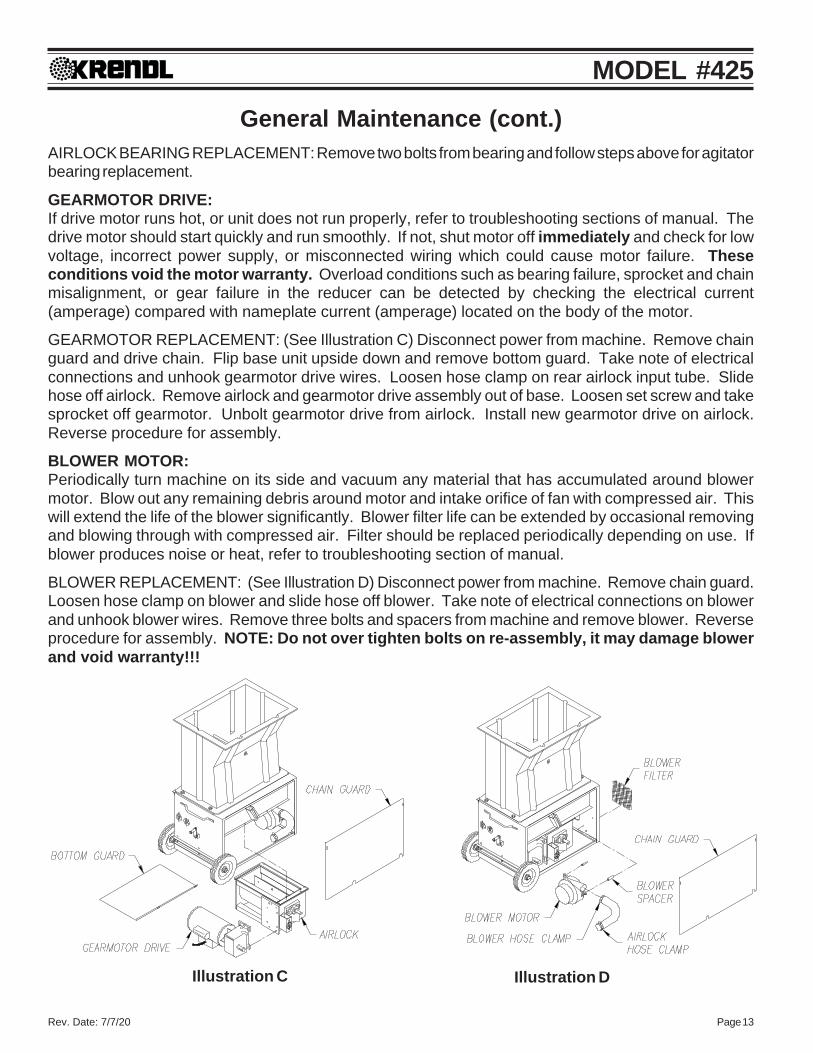
GEARMOTOR REPLACEMENT: (See Illustration C) Disconnect power from machine. Remove chainguard and drive chain. Flip base unit upside down and remove bottom guard. Take note of electricalconnections and unhook gearmotor drive wires. Loosen hose clamp on rear airlock input tube. Slidehose off airlock. Remove airlock and gearmotor drive assembly out of base. Loosen set screw and takesprocket off gearmotor. Unbolt gearmotor drive from airlock. Install new gearmotor drive on airlock.Reverse procedure for assembly.
BLOWER MOTOR:Periodically turn machine on its side and vacuum any material that has accumulated around blowermotor. Blow out any remaining debris around motor and intake orifice of fan with compressed air. Thiswill extend the life of the blower significantly. Blower filter life can be extended by occasional removingand blowing through with compressed air. Filter should be replaced periodically depending on use. Ifblower produces noise or heat, refer to troubleshooting section of manual.
BLOWER REPLACEMENT: (See Illustration D) Disconnect power from machine. Remove chain guard.Loosen hose clamp on blower and slide hose off blower. Take note of electrical connections on blowerand unhook blower wires. Remove three bolts and spacers from machine and remove blower. Reverseprocedure for assembly. NOTE: Do not over tighten bolts on re-assembly, it may damage blowerand void warranty!!!
Illustration C Illustration D
Rev. Date: 7/7/20 Page 14
MODEL #425
Illustration E
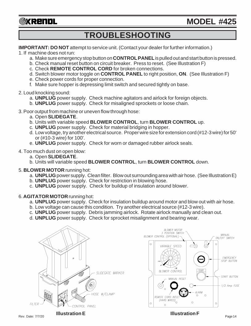
TROUBLESHOOTINGIMPORTANT: DO NOT attempt to service unit. (Contact your dealer for further information.)1. If machine does not run:
a. Make sure emergency stop button on CONTROL PANEL is pulled out and start button is pressed.b. Check manual reset button on circuit breaker. Press to reset. (See Illustration F)c. Check REMOTE CONTROL CORD for broken connections.d. Switch blower motor toggle on CONTROL PANEL to right position, ON. (See Illustration F)e. Check power cords for proper connection.f. Make sure hopper is depressing limit switch and secured tightly on base.
2. Loud knocking sound:a. UNPLUG power supply. Check machine agitators and airlock for foreign objects.b. UNPLUG power supply. Check for misaligned sprockets or loose chain.
3. Poor output from machine or uneven flow through hose:a. Open SLIDEGATE.b. Units with variable speed BLOWER CONTROL, turn BLOWER CONTROL up.c. UNPLUG power supply. Check for material bridging in hopper.d. Low voltage, try another electrical source. Proper wire size for extension cord (#12-3 wire) for 50'
or (#10-3 wire) for 100'.e. UNPLUG power supply. Check for worn or damaged rubber airlock seals.
4. Too much dust on open blow:a. Open SLIDEGATE.b. Units will variable speed BLOWER CONTROL, turn BLOWER CONTROL down.
5. BLOWER MOTOR running hot:a. UNPLUG power supply. Clean filter. Blow out surrounding area with air hose. (See Illustration E)b. UNPLUG power supply. Check for restriction in blowing hose.c. UNPLUG power supply. Check for buildup of insulation around blower.
6. AGITATOR MOTOR running hot:a. UNPLUG power supply. Check for insulation buildup around motor and blow out with air hose.b. Low voltage can cause this condition. Try another electrical source (#12-3 wire).c. UNPLUG power supply. Debris jamming airlock. Rotate airlock manually and clean out.d. UNPLUG power supply. Check for sprocket misalignment and bearing wear.
Illustration F
Rev. Date: 7/7/20 Page 15
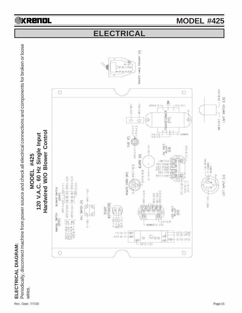
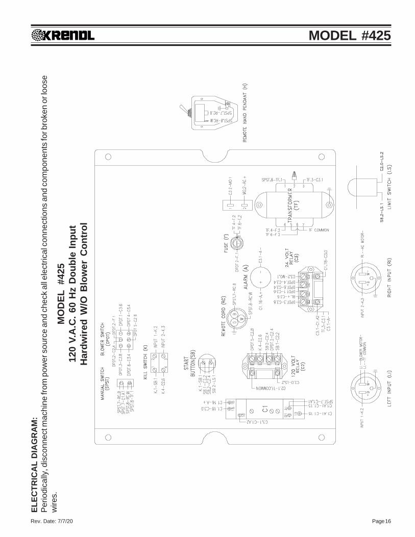
MODEL #425ELECTRICAL
MO
DEL
#42
512
0 V.
A.C
. 60
Hz
Sing
le In
put
Har
dwire
d W
/O B
low
er C
ontr
ol
ELEC
TRIC
AL
DIA
GR
AM
:Pe
riodi
cally
, dis
conn
ect m
achi
ne fr
om p
ower
sou
rce
and
chec
k al
l ele
ctric
al c
onne
ctio
ns a
nd c
ompo
nent
s fo
r bro
ken
or lo
ose
wire
s.
Rev. Date: 7/7/20 Page 16
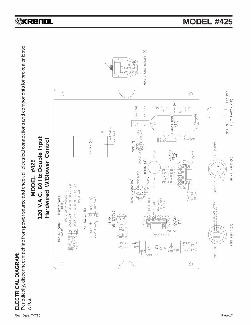
MODEL #425M
OD
EL #
425
120
V.A
.C. 6
0 H
z D
oubl
e In
put
Har
dwire
d W
/O B
low
er C
ontr
ol
ELEC
TRIC
AL
DIA
GR
AM
:Pe
riodi
cally
, dis
conn
ect m
achi
ne fr
om p
ower
sou
rce
and
chec
k al
l ele
ctric
al c
onne
ctio
ns a
nd c
ompo
nent
s fo
r bro
ken
or lo
ose
wire
s.
Rev. Date: 7/7/20 Page 17
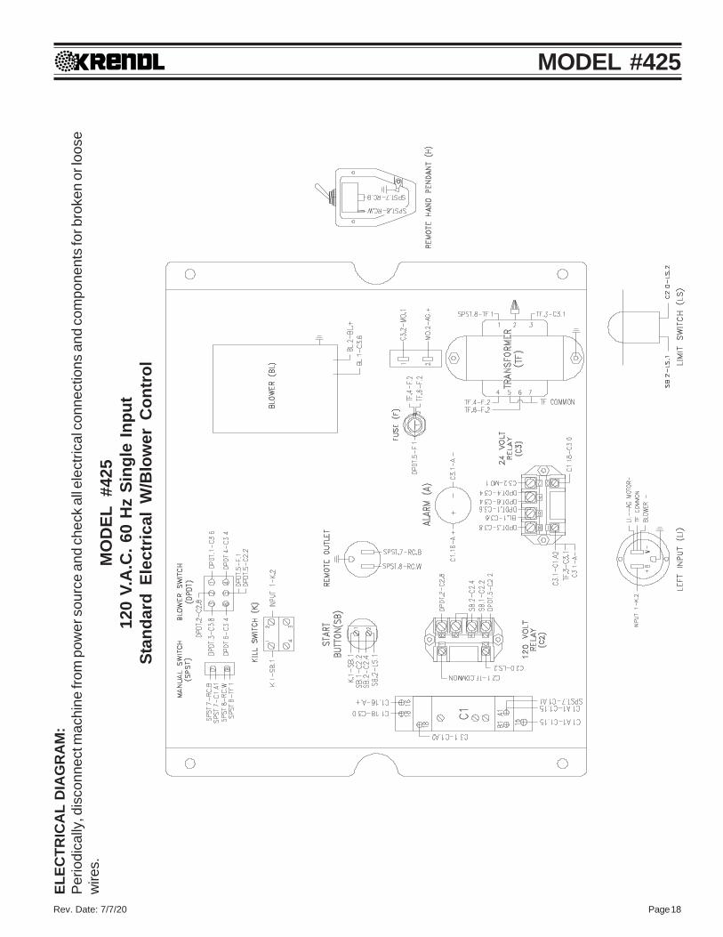
MODEL #425M
OD
EL #
425
120
V.A
.C. 6
0 H
z D
oubl
e In
put
Har
dwire
d W
/Blo
wer
Con
trol
ELEC
TRIC
AL
DIA
GR
AM
:Pe
riodi
cally
, dis
conn
ect m
achi
ne fr
om p
ower
sou
rce
and
chec
k al
l ele
ctric
al c
onne
ctio
ns a
nd c
ompo
nent
s fo
r bro
ken
or lo
ose
wire
s.
Rev. Date: 7/7/20 Page 18
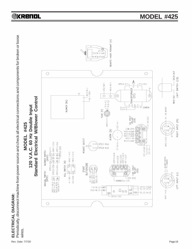
MODEL #425M
OD
EL #
425
120
V.A
.C. 6
0 H
z Si
ngle
Inpu
tSt
anda
rd E
lect
rical
W/B
low
er C
ontr
ol
ELEC
TRIC
AL
DIA
GR
AM
:Pe
riodi
cally
, dis
conn
ect m
achi
ne fr
om p
ower
sou
rce
and
chec
k al
l ele
ctric
al c
onne
ctio
ns a
nd c
ompo
nent
s fo
r bro
ken
or lo
ose
wire
s.
Rev. Date: 7/7/20 Page 19
MODEL #425M
OD
EL #
425
120
V.A
.C. 6
0 H
z D
oubl
e In
put
Stan
dard
Ele
ctric
al W
/Blo
wer
Con
trol
ELEC
TRIC
AL
DIA
GR
AM
:Pe
riodi
cally
, dis
conn
ect m
achi
ne fr
om p
ower
sou
rce
and
chec
k al
l ele
ctric
al c
onne
ctio
ns a
nd c
ompo
nent
s fo
r bro
ken
or lo
ose
wire
s.
Rev. Date: 7/7/20 Page 20
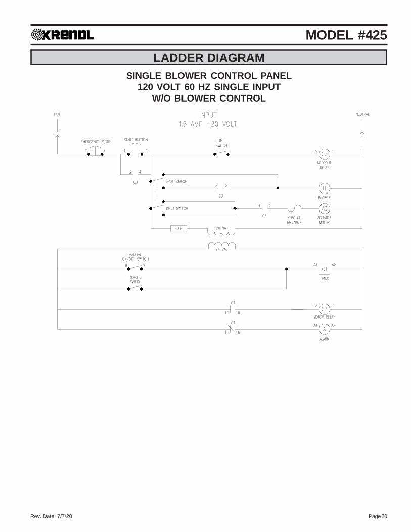
MODEL #425LADDER DIAGRAM
SINGLE BLOWER CONTROL PANEL120 VOLT 60 HZ SINGLE INPUT
W/O BLOWER CONTROL

Rev. Date: 7/7/20 Page 21
MODEL #425LADDER DIAGRAM
SINGLE BLOWER CONTROL PANEL120 VOLT 60 HZ DOUBLE INPUT
W/O BLOWER CONTROL
Rev. Date: 7/7/20 Page 22
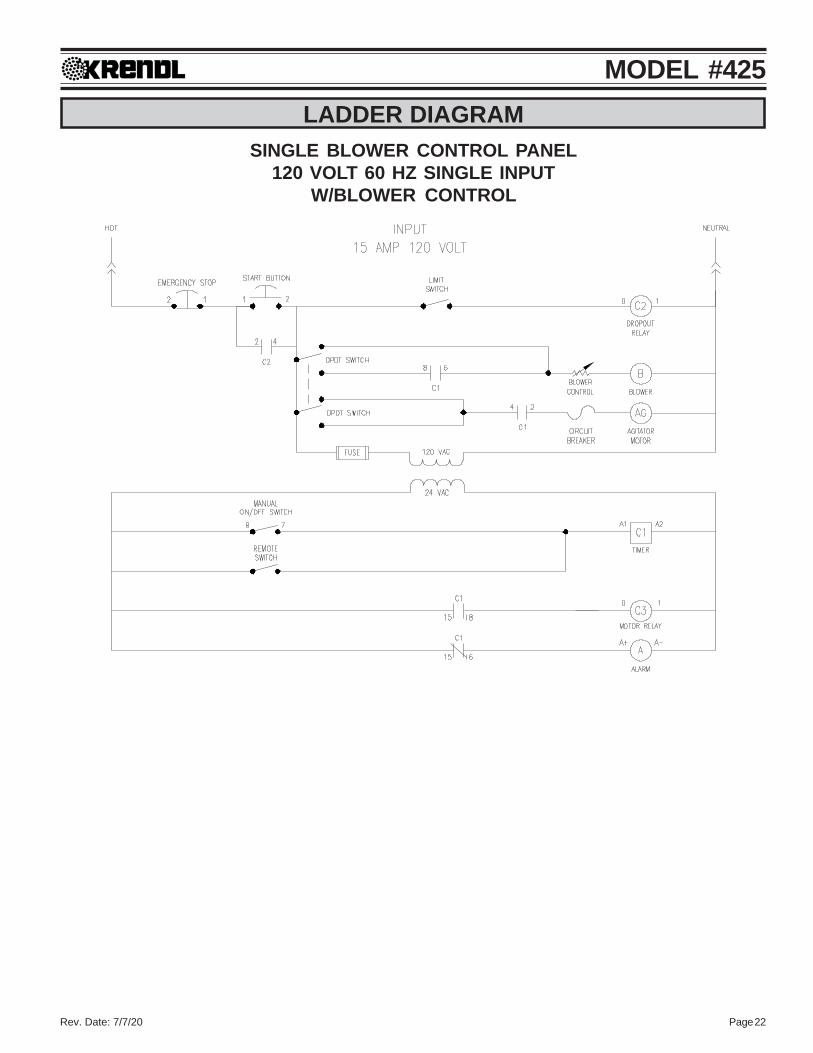
MODEL #425LADDER DIAGRAM
SINGLE BLOWER CONTROL PANEL120 VOLT 60 HZ SINGLE INPUT
W/BLOWER CONTROL
Rev. Date: 7/7/20 Page 23
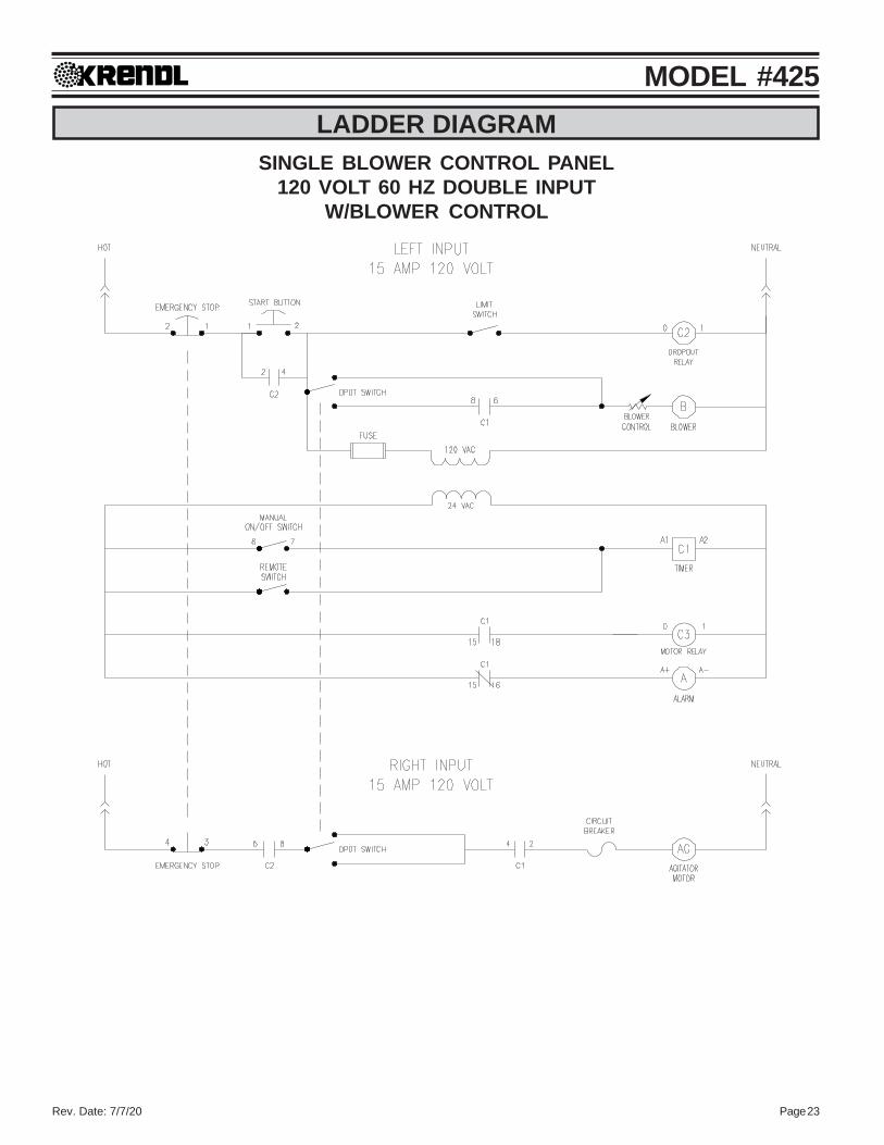
MODEL #425LADDER DIAGRAM
SINGLE BLOWER CONTROL PANEL120 VOLT 60 HZ DOUBLE INPUT
W/BLOWER CONTROL
Rev. Date: 7/7/20 Page 24
MODEL #425EXPLODED PARTS
#425 Machine
Rev. Date: 7/7/20 Page 25
MODEL #425
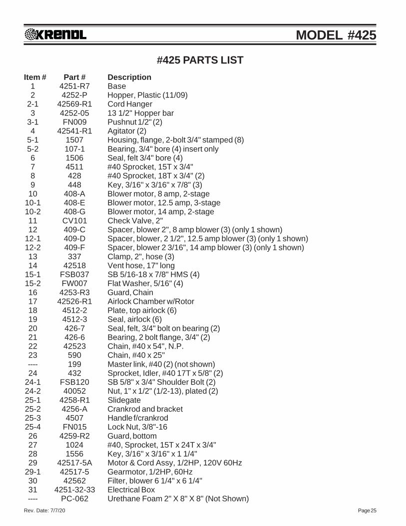
#425 PARTS LISTItem # Part # Description
1 4251-R7 Base2 4252-P Hopper, Plastic (11/09)
2-1 42569-R1 Cord Hanger3 4252-05 13 1/2" Hopper bar
3-1 FN009 Pushnut 1/2" (2)4 42541-R1 Agitator (2)
5-1 1507 Housing, flange, 2-bolt 3/4" stamped (8)5-2 107-1 Bearing, 3/4" bore (4) insert only6 1506 Seal, felt 3/4" bore (4)7 4511 #40 Sprocket, 15T x 3/4"8 428 #40 Sprocket, 18T x 3/4" (2)9 448 Key, 3/16" x 3/16" x 7/8" (3)
10 408-A Blower motor, 8 amp, 2-stage10-1 408-E Blower motor, 12.5 amp, 3-stage10-2 408-G Blower motor, 14 amp, 2-stage11 CV101 Check Valve, 2"12 409-C Spacer, blower 2", 8 amp blower (3) (only 1 shown)
12-1 409-D Spacer, blower, 2 1/2", 12.5 amp blower (3) (only 1 shown)12-2 409-F Spacer, blower 2 3/16", 14 amp blower (3) (only 1 shown)13 337 Clamp, 2", hose (3)14 42518 Vent hose, 17" long
15-1 FSB037 SB 5/16-18 x 7/8" HMS (4)15-2 FW007 Flat Washer, 5/16" (4)16 4253-R3 Guard, Chain17 42526-R1 Airlock Chamber w/Rotor18 4512-2 Plate, top airlock (6)19 4512-3 Seal, airlock (6)20 426-7 Seal, felt, 3/4" bolt on bearing (2)21 426-6 Bearing, 2 bolt flange, 3/4" (2)22 42523 Chain, #40 x 54", N.P.23 590 Chain, #40 x 25"---- 199 Master link, #40 (2) (not shown)24 432 Sprocket, Idler, #40 17T x 5/8" (2)
24-1 FSB120 SB 5/8" x 3/4" Shoulder Bolt (2)24-2 40052 Nut, 1" x 1/2" (1/2-13), plated (2)25-1 4258-R1 Slidegate25-2 4256-A Crankrod and bracket25-3 4507 Handle f/crankrod25-4 FN015 Lock Nut, 3/8"-1626 4259-R2 Guard, bottom27 1024 #40, Sprocket, 15T x 24T x 3/4"28 1556 Key, 3/16" x 3/16" x 1 1/4"29 42517-5A Motor & Cord Assy, 1/2HP, 120V 60Hz
29-1 42517-5 Gearmotor, 1/2HP, 60Hz30 42562 Filter, blower 6 1/4" x 6 1/4"31 4251-32-33 Electrical Box---- PC-062 Urethane Foam 2" X 8" X 8" (Not Shown)
Rev. Date: 7/7/20 Page 26
MODEL #425#425 PARTS LIST
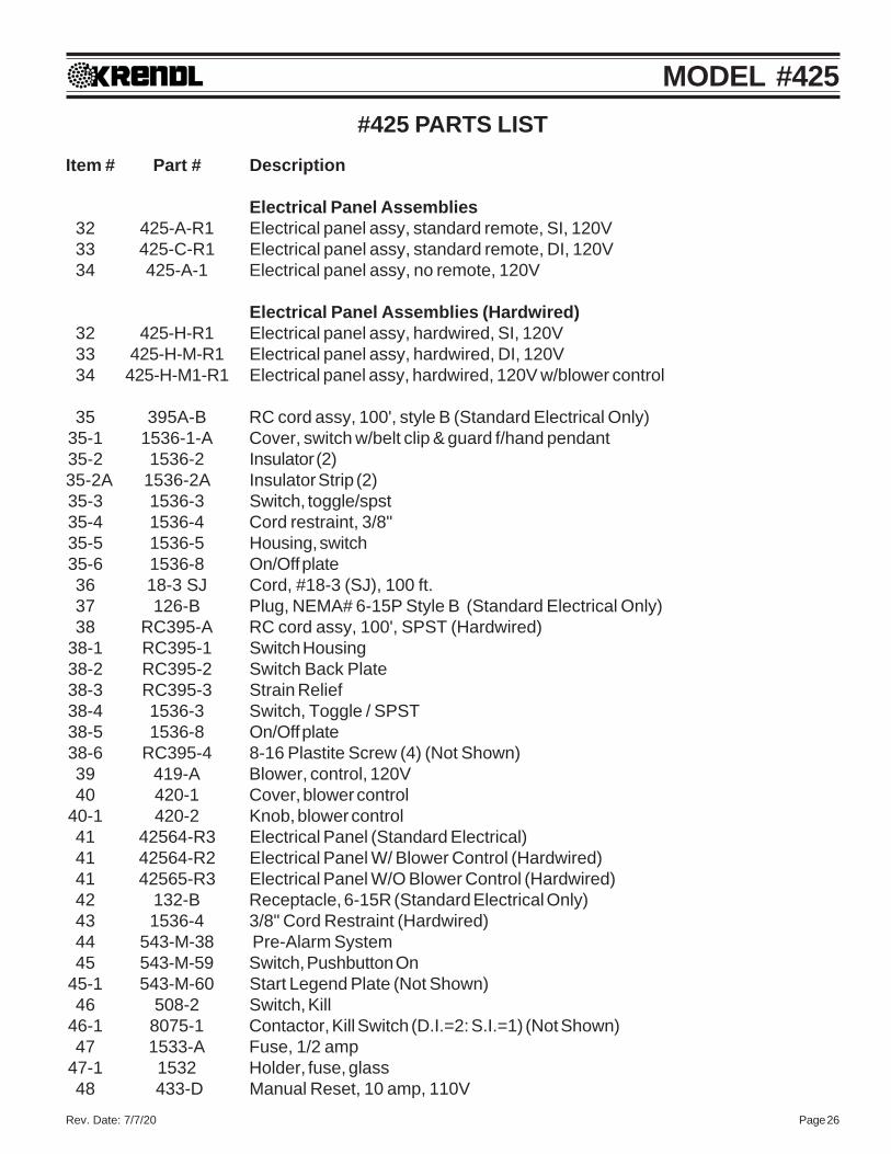
Item # Part # Description
Electrical Panel Assemblies32 425-A-R1 Electrical panel assy, standard remote, SI, 120V33 425-C-R1 Electrical panel assy, standard remote, DI, 120V34 425-A-1 Electrical panel assy, no remote, 120V
Electrical Panel Assemblies (Hardwired)32 425-H-R1 Electrical panel assy, hardwired, SI, 120V33 425-H-M-R1 Electrical panel assy, hardwired, DI, 120V34 425-H-M1-R1 Electrical panel assy, hardwired, 120V w/blower control
35 395A-B RC cord assy, 100', style B (Standard Electrical Only)35-1 1536-1-A Cover, switch w/belt clip & guard f/hand pendant35-2 1536-2 Insulator (2)35-2A 1536-2A Insulator Strip (2)35-3 1536-3 Switch, toggle/spst35-4 1536-4 Cord restraint, 3/8"35-5 1536-5 Housing, switch35-6 1536-8 On/Off plate36 18-3 SJ Cord, #18-3 (SJ), 100 ft.37 126-B Plug, NEMA# 6-15P Style B (Standard Electrical Only)38 RC395-A RC cord assy, 100', SPST (Hardwired)
38-1 RC395-1 Switch Housing38-2 RC395-2 Switch Back Plate38-3 RC395-3 Strain Relief38-4 1536-3 Switch, Toggle / SPST38-5 1536-8 On/Off plate38-6 RC395-4 8-16 Plastite Screw (4) (Not Shown)39 419-A Blower, control, 120V40 420-1 Cover, blower control
40-1 420-2 Knob, blower control41 42564-R3 Electrical Panel (Standard Electrical)41 42564-R2 Electrical Panel W/ Blower Control (Hardwired)41 42565-R3 Electrical Panel W/O Blower Control (Hardwired)42 132-B Receptacle, 6-15R (Standard Electrical Only)43 1536-4 3/8" Cord Restraint (Hardwired)44 543-M-38 Pre-Alarm System45 543-M-59 Switch, Pushbutton On
45-1 543-M-60 Start Legend Plate (Not Shown)46 508-2 Switch, Kill
46-1 8075-1 Contactor, Kill Switch (D.I.=2: S.I.=1) (Not Shown)47 1533-A Fuse, 1/2 amp
47-1 1532 Holder, fuse, glass48 433-D Manual Reset, 10 amp, 110V
Rev. Date: 7/7/20 Page 27
MODEL #425#425 PARTS LIST
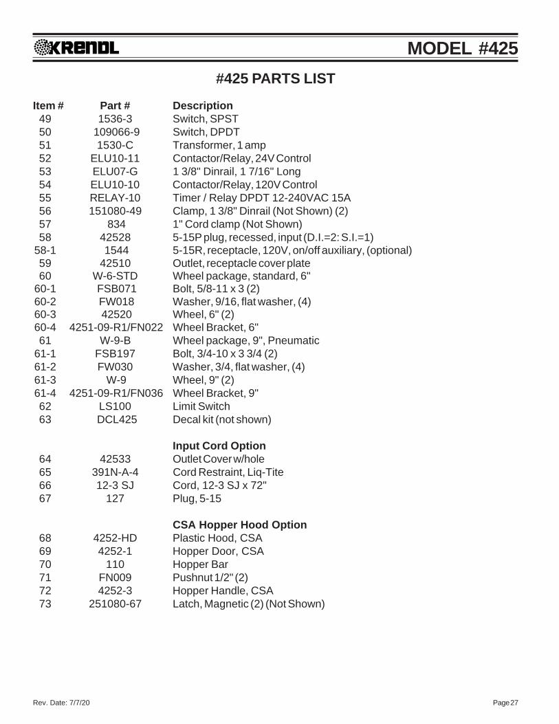
Item # Part # Description49 1536-3 Switch, SPST50 109066-9 Switch, DPDT51 1530-C Transformer, 1 amp52 ELU10-11 Contactor/Relay, 24V Control53 ELU07-G 1 3/8" Dinrail, 1 7/16" Long54 ELU10-10 Contactor/Relay, 120V Control55 RELAY-10 Timer / Relay DPDT 12-240VAC 15A56 151080-49 Clamp, 1 3/8" Dinrail (Not Shown) (2)57 834 1" Cord clamp (Not Shown)58 42528 5-15P plug, recessed, input (D.I.=2: S.I.=1)
58-1 1544 5-15R, receptacle, 120V, on/off auxiliary, (optional)59 42510 Outlet, receptacle cover plate60 W-6-STD Wheel package, standard, 6"
60-1 FSB071 Bolt, 5/8-11 x 3 (2)60-2 FW018 Washer, 9/16, flat washer, (4)60-3 42520 Wheel, 6" (2)60-4 4251-09-R1/FN022 Wheel Bracket, 6"61 W-9-B Wheel package, 9", Pneumatic
61-1 FSB197 Bolt, 3/4-10 x 3 3/4 (2)61-2 FW030 Washer, 3/4, flat washer, (4)61-3 W-9 Wheel, 9" (2)61-4 4251-09-R1/FN036 Wheel Bracket, 9"62 LS100 Limit Switch63 DCL425 Decal kit (not shown)
Input Cord Option64 42533 Outlet Cover w/hole65 391N-A-4 Cord Restraint, Liq-Tite66 12-3 SJ Cord, 12-3 SJ x 72"67 127 Plug, 5-15
CSA Hopper Hood Option68 4252-HD Plastic Hood, CSA69 4252-1 Hopper Door, CSA70 110 Hopper Bar71 FN009 Pushnut 1/2" (2)72 4252-3 Hopper Handle, CSA73 251080-67 Latch, Magnetic (2) (Not Shown)
Rev. Date: 7/7/20 Page 28
MODEL #425GLOSSARY
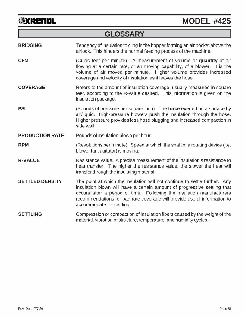
BRIDGING Tendency of insulation to cling in the hopper forming an air pocket above theairlock. This hinders the normal feeding process of the machine.
CFM (Cubic feet per minute). A measurement of volume or quantity of airflowing at a certain rate, or air moving capability, of a blower. It is thevolume of air moved per minute. Higher volume provides increasedcoverage and velocity of insulation as it leaves the hose.
COVERAGE Refers to the amount of insulation coverage, usually measured in squarefeet, according to the R-value desired. This information is given on theinsulation package.
PSI (Pounds of pressure per square inch). The force exerted on a surface byair/liquid. High-pressure blowers push the insulation through the hose.Higher pressure provides less hose plugging and increased compaction inside wall.
PRODUCTION RATE Pounds of insulation blown per hour.
RPM (Revolutions per minute). Speed at which the shaft of a rotating device (i.e.blower fan, agitator) is moving.
R-VALUE Resistance value. A precise measurement of the insulation's resistance toheat transfer. The higher the resistance value, the slower the heat willtransfer through the insulating material.
SETTLED DENSITY The point at which the insulation will not continue to settle further. Anyinsulation blown will have a certain amount of progressive settling thatoccurs after a period of time. Following the insulation manufacturersrecommendations for bag rate coverage will provide useful information toaccommodate for settling.
SETTLING Compression or compaction of insulation fibers caused by the weight of thematerial, vibration of structure, temperature, and humidity cycles.
Rev. Date: 7/7/20 Page 29
MODEL #425SERVICE RECORD
DATE MAINTENANCE PERFORMED COMPONENTS REQUIRED

KRENDL MACHINE COMPANY • 1201 SPENCERVILLE RDDELPHOS, OHIO 45833 • TELEPHONE 800-459-2069 • FAX 419-695-9301
E - MAIL: [email protected] • WEB SITE: www.krendlmachine.com
60 YEARSOF AMERICAN INGENUITY
Made in the U.S.A.