Embed Size (px)
Citation preview
422 IEEE TRANSACTIONS ON ENERGY CONVERSION, VOL. 25, NO. 2, JUNE 2010
A Series-Dynamic-Resistor-Based ConverterProtection Scheme for Doubly-Fed InductionGenerator During Various Fault ConditionsJin Yang, Student Member, IEEE, John E. Fletcher, and John O’Reilly, Senior Member, IEEE
Abstract—This paper proposes a new converter protectionmethod, primarily based on a series dynamic resistor (SDR) thatavoids the doubly-fed induction generator (DFIG) control beingdisabled by crowbar protection during fault conditions. A com-bined converter protection scheme based on the proposed SDR andconventional crowbar is analyzed and discussed. The main protec-tion advantages are due to the series topology when comparedwith crowbar and dc-chopper protection. Various fault overcur-rent conditions (both symmetrical and asymmetrical) are analyzedand used to design the protection in detail, including the switchingstrategy and coordination with crowbar, and resistance value cal-culations. PSCAD/EMTDC simulation results show that the pro-posed method is advantageous for fault overcurrent protection,especially for asymmetrical faults, in which the traditional crow-bar protection may malfunction.
Index Terms—Converter protection scheme, doubly-fed induc-tion generator (DFIG), fault ride-through (FRT), series dynamicresistor (SDR), wind power generation.
NOMENCLATURE
Ls, Lr , Lls , Llr Stator, rotor self- and leakage inductances.Lm Magnetizing inductance.Ps,Qs Stator-side active and reactive power.Rs,Rr Stator, rotor resistances.v,i, ψ Voltage, current, and flux vectors.Vs, Vr Stator, rotor voltage amplitudes.ωs, ωr , sωs Synchronous, rotor, and slip angular fre-
quencies.τs, τr , τ Stator, rotor, and combined time constants.s, r Stator and rotor subscripts.n Nominal value subscript.
I. INTRODUCTION
LARGE-SCALE offshore wind farms are gradually grow-ing all around the world, especially in Europe, where off-
shore wind resources are rich and located in shallow water. By2020, 20% of power consumption in Europe will be suppliedfrom renewable resources. The realization of this ambitious plan
Manuscript received August 14, 2009; revised November 20, 2009; acceptedNovember 24, 2009. Date of publication February 2, 2010; date of currentversion May 21, 2010. Paper no. TEC-00329-2009.
J. Yang and J. O’Reilly are with the Department of Electronics and Elec-trical Engineering, University of Glasgow, Glasgow, G12 8LT, U.K. (e-mail:[email protected]; [email protected]).
J. E. Fletcher is with the Department of Electronic and Electrical En-gineering, University of Strathclyde, Glasgow, G1 1XW, U.K. (e-mail:[email protected]).
Color versions of one or more of the figures in this paper are available onlineat http://ieeexplore.ieee.org.
Digital Object Identifier 10.1109/TEC.2009.2037970
relies heavily on the large-scale offshore wind farms. For theU.K.’s 2020 target, offshore wind farms will contribute as muchas 9.4% [1]. There is now planning for more than 30 GW of off-shore wind farm capacity in the European seas by 2015—almost30 times more than the current installation [2]. Therefore, thereliability of offshore wind farms needs to be assessed in de-tail because of the costly maintenance and repair in the offshoreenvironment. The reliability is distributed between the wind tur-bines, the wind power generation systems, the collection grid,and the transmission system [3].
For wind power generation systems, the doubly-fed inductiongenerator (DFIG), with its variable wind speed tracking perfor-mance, and relatively low cost compared to fully rated con-verter wind power generation system, e.g., permanent-magnetsynchronous generator (PMSG), is a popular wind generationconcept. However, a significant disadvantage of the DFIG is itsvulnerability to grid disturbances because the stator windingsare connected directly to the grid through a transformer andswitchgear with only the rotor-side buffered from the grid via apartially rated converter. Therefore, as to protect the wind farmfrom interruptions due to onshore grid faults and wind farmfaults, crowbar protects the induction generator and associatedpower electronics. This is widely used in industrial applications.
A major disadvantage of crowbar protection is that the rotor-side converter (RSC) has to be disabled when using the crowbarand the generator consumes reactive power leading to deterio-ration of grid voltage. In line with developing fault ride-through(FRT) requirements, an active crowbar control scheme is pro-posed [4], [5] to shorten the time the crowbar is in operationbut this does not avoid the reactive power consumption. Someresearchers developed a new fault-control strategy [6] or a fault-tolerant series grid-side converter topology [7]. However, thesemake the control systems complex or increase the issues withcontrol coordination between normal and fault operation.
A series topology can drop rotor circuit voltage hence limitingthe current, and is an alternative to crowbar protection. However,to the authors’ knowledge, there has been no published literatureon a series topology protection schemes. Therefore, this researchassesses series protection for effective turbine and converterprotection during various fault conditions.
The paper is organized as follows. In Section II, the existingprotection schemes for variable-speed wind turbine generationsystems, including DFIGs and PMSGs, are summarized. Then,a protection scheme with series dynamic resistor (SDR) con-nected to the rotor winding is proposed. The faults that can occurin wind farms and the currents in the rotor windings of DFIGs
0885-8969/$26.00 © 2010 IEEE
YANG et al.: SERIES-DYNAMIC-RESISTOR-BASED CONVERTER PROTECTION SCHEME 423
are discussed in detail as the basis of the converter protectionscheme design: fault rotor current expressions are given theo-retically and with simulation results; and the difference betweenrotor current characteristics for symmetrical and asymmetricalfaults is discussed which highlights the advantage SDRs as theprimary protection of the converter. In Section IV, a new con-verter protection scheme combining the SDR and the crowbar isintroduced. Analysis and discussion of PSCAD/EMTDC simu-lations are provided in Sections III and V.
II. CONVERTER PROTECTION SCHEMES FOR DFIG
A. Crowbar Protection
The prevalent DFIG protection scheme is crowbar protection.A crowbar is a set of resistors that are connected in parallel withthe rotor winding on occurrence of an interruption, bypassingthe RSC. The active crowbar control scheme connects the crow-bar resistance when necessary and disables it to resume DFIGcontrol.
For active crowbar control schemes, the control signals areactivated by the RSC devices [which are usually insulated gatebipolar transistors (IGBTs)]. These have voltage and currentlimits that must not be exceeded. Therefore, the RSC voltagesand currents are the critical regulation reference. The dc-linkbus voltage can increase rapidly under these conditions, so itis also used as a monitored variable for crowbar triggering.Bidirectional thyristors [8], gate turn-OFF thyristors (GTOs) [5],[9], or IGBTs [10] are typically used for crowbar switching.
B. DC-Chopper
In [5] and [11], a braking resistor (dc-chopper) is connected inparallel with the dc-link capacitor to limit the overcharge duringlow grid voltage. This protects the IGBTs from overvoltage andcan dissipate energy, but this has no effect on the rotor current.It is also used as protection for the dc-link capacitor in full ratedconverter topologies, for example, PMSGs [12].
C. Series Dynamic Resistor
In a similar way to the series dynamic braking resistor [13],which has been used in the stator side of generators, a dynamicresistor is proposed to be put in series with the rotor (SDR) andthis limits the rotor overcurrent. Being controlled by a power-electronic switch, in normal operation, the switch is on and theresistor is bypassed; during fault conditions, the switch is OFF
and the resistor is connected in series to the rotor winding.The difference between the SDR and the crowbar or dc-link
braking resistor is its topology. The latter are shunt-connectedand control the voltage while the SDR has the distinct advantageof controlling the current magnitude directly. Moreover, with theSDR, the high voltage will be shared by the resistance becauseof the series topology; therefore, the induced overvoltage maynot lead to the loss of converter control. Therefore, it not onlycontrols the rotor overvoltage which could cause the RSC tolose control, but, more significantly, limits high rotor current.In addition, the limited current can reduce the charging currentto the dc-link capacitor, hence avoiding dc-link overvoltage.
Therefore, with the SDR, the RSC does not need to be inhibitedduring the fault.
The crowbar is adequate for protection of the wind turbinesystem during grid faults in on-shore developments. The influ-ence of temporarily losing rotor-side control of DFIGs can beneglected—which is not presently the case for large-scale off-shore wind farms. The series topology is straightforward enoughto limit the overcurrent and share overvoltage, but there appearsto be no literature investigating their use.
To show the protection schemes and their interaction withthe rotor circuit, the rotor equivalent circuit is described firstwith the general Park’s model of induction generators. From thevoltage and flux equations of induction generators in a staticstator-oriented reference frame [14]
vs = Rsis +
dψs
dt(1)
vr = Rrir +
dψr
dt− jωr
ψr (2)
ψs = Lsis + Lm
ir (3)
ψr = Lmis + Lr
ir (4)
where vs is imposed by the grid. The rotor voltage vr is con-trolled by the RSC and used to perform generator control.
From (3) and (4), we can eliminateis and obtain an expres-sion, which is substituted into (2); eliminating ψr gives
vr =Lm
Ls
(d
dt− jωr
)ψs
+[Rr + Lr
(1 − L2
m
LsLr
)(d
dt− jωr
)]·ir . (5)
Defining the leakage factor as
σ = 1 − L2m
LsLr. (6)
Then, using a voltage source vro to represent the voltage dueto the stator flux produces
vro =Lm
Ls
(d
dt− jωr
)ψs. (7)
Therefore, (5) becomes
vr = vro +[Rr + σLr
(d
dt− jωr
)]·ir . (8)
The rotor voltage in (8) can be expressed in a rotor referenceframe (i.e., multiply both sides by e−jωr t)
v rr = v r
ro + Rr ·i rr + σLr
di rr
dt. (9)
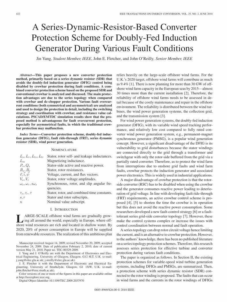
This is the relationship between rotor voltage and current.Therefore, the rotor equivalent circuit is obtained and shownwith all the earlier protection schemes in Fig. 1.
III. DFIG ROTOR CURRENTS DURING FAULT CONDITIONS
DFIG rotor currents under three-phase short-circuit fault havebeen thoroughly analyzed. In [15], exact expressions of stator
424 IEEE TRANSACTIONS ON ENERGY CONVERSION, VOL. 25, NO. 2, JUNE 2010
Fig. 1. DFIG rotor equivalent circuit with all protection schemes shown.
and rotor currents during the short circuit are derived mathe-matically. The approximate maximum stator fault current ex-pression was also discussed from the analysis of DFIG physicalresponse with crowbar protection [8]. However, there has beenno analysis of fault currents during less serious voltage dips orasymmetrical disturbances. Nonetheless, this is important forthe design of DFIG protection systems. In this paper, the ro-tor current expressions during various fault conditions will bededuced on the basis of the analysis of [14], [16].
The phase-a voltage expression is
vra(t) = Rev rro + Rr · ira(t) + σLr
dira(t)dt
. (10)
This can be written as a linear differential equation for ira (t)
i′ra(t) +Rr
σLrira(t) =
1σLr
[vra(t) − Rev rro] (11)
where with converter in operation, let vra(t) = Vr cos(sωst +β), β is the phase-a rotor voltage angle at the instant the faultoccurs.
A. Symmetrical Fault Conditions
For a symmetrical voltage disturbance on the stator side,if there is a three-phase step amplitude change from Vs to(1 − p)Vs (p is the voltage dip ratio), v r
ro in (9) can exceed themaximum voltage that the rotor converter can generate, whichcauses the failure of current control. The voltage is [16]
v rro = (1 − p)Vs
Lm
Lssejsωs t − Lm
Ls
(1τs
+ jωr
)pVs
jωse−t/τs .
(12)With time constants defined as
τr =σLr
Rr; τs =
Ls
Rs; τ =
τr τs
τs − τr(13)
Equation (12) can be simplified by omitting 1/τs , which is verysmall because of the small stator resistance of the generator,therefore
v rro ≈ Vs
Lm
Ls[s(1 − p)ejsωs t − (1 − s)pe−jωr te−t/τs ]. (14)
From (11) and (14), the final expression of ira(t) can besolved and divided into four components
ira(t) = idc + ivr + ivrf + ivrn (15)
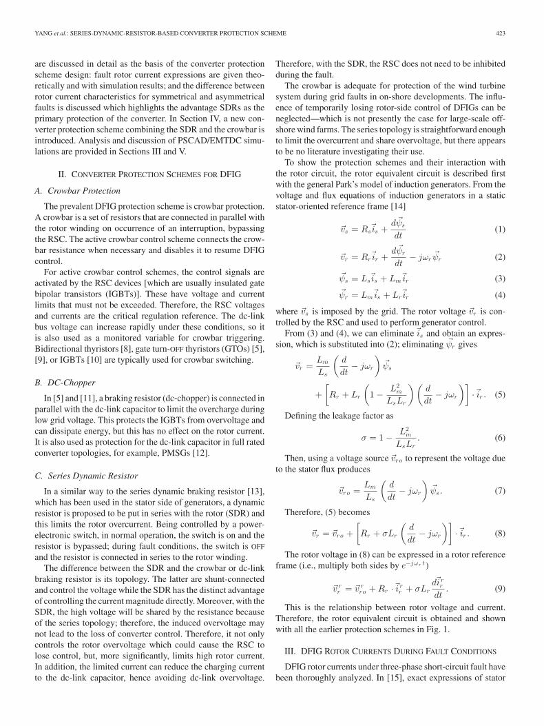
TABLE ISYMMETRICAL FAULT ROTOR CURRENT COMPONENTS
where the components are
idc =
ira(t−0 ) − 1σLr
τr
1 + τ 2r (sωs)2
×[Vr cos β − Vs
Lm
Lss(1 − p)
]
− 1σLr
VsLm
Ls(1 − s)p
τ
1 + τ 2ω2r
e−t/τr (16)
ivr =Vr
σLr
[τr
1 + τ 2r ω2
r
cos(sωst + β)
+τ 2r ωr
1 + τ 2r ω2
r
sin(sωst + β)]
(17)
ivrf = − 1σLr
VsLm
Lss(1 − p) ×
[τr
1 + τ 2r (sωs)
2 cos(sωst)
+τ 2r sωs
1 + τ 2r (sωs)
2 sin(sωst)]
(18)
ivrn =Vs
σLr
Lm
Ls(1 − s)p ×
[τ
1 + τ 2ω2r
cos(ωr t)
+τ 2ωr
1 + τ 2ω2r
sin(ωr t)]e−t/τs . (19)
The components are listed in Table I with frequency anddecaying time constant characteristics.
B. Asymmetrical Fault Conditions
For asymmetrical faults, the stator voltage is divided into threeparts: positive-, negative-, and zero-sequence components, in theuse of symmetrical components theory [16]:
vs = Vs1ejωs t + Vs2e
−jωs t + Vs0 . (20)
Then, v rro in (9) can also be expressed as
v rro = v r
r1 + v rr2 + v r
rn (21)
where
v rr1 = Vs1
Lm
Lssejsωs t (22)
v rr2 = Vs2
Lm
Ls(s − 2)e−j (2−s)ωs t (23)
vrrn ≈ −jωr
Lm
Ls
ψn0e−t/τs e−jωr t . (24)
The components Vs1 , Vs2 , Vs0 , and ψn0 depend on the typeof fault.
YANG et al.: SERIES-DYNAMIC-RESISTOR-BASED CONVERTER PROTECTION SCHEME 425
1) Single-Phase Voltage Dip: Phase a suffers a voltage dip.The positive-, negative-, and zero-sequence components of thestator voltage are
Vs1 = Vs
(1 − p
3
)
Vs2 = Vs
(−p
3
)
Vs0 = Vs
(−p
3
)(25)
where p is the phase-a voltage dip ratio due to the fault. There-fore, the aforementioned v r
r0 components are
v rr1 = Vs
(1 − p
3
) Lm
Lssejsωs t (26)
v rr2 = Vs
(−p
3
) Lm
Ls(s − 2)e−j (2−s)ωs t . (27)
From the natural flux initial value analysis in [16]
ψn0 =Vs(2/3)p
ωs(28)
v rrn ≈ −j
23Vs
Lm
Ls(1 − s)pe−t/τs e−jωr t (29)
hence
vro ≈ VsLm
Lss(1 − p
3
)ejsωs t − Vs
Lm
Ls(s − 2)
p
3e−j (2−s)ωs t
− j23Vs
Lm
Ls(1 − s)pe−t/τs e−jωr t . (30)
From (11) and (30), the final expression of ira(t) can besolved and divided into five components
ira(t) = idc + ivr + ivr1 + ivr2 + ivrn (31)
where the components are solved as
idc =
ira(t−0 ) − 1σLr
τr
1 + τ 2r (sωs)
2
×[Vr cos β − Vs
Lm
Lss(1 − p
3
)]
− 1σLr
VsLm
Ls
[(s − 2)
p
3τr
1 + τ 2r (2 − s)2ω2
s
+23(1 − s)p
−τ 2ωr
1 + τ 2ω2r
]e−t/τr (32)
ivr =Vr
σLr
[τr
1 + τ 2r ω2
r
cos(sωst + β)
+τ 2r ωr
1 + τ 2r ω2
r
sin(sωst + β)]
(33)
ivr1 = − Vs
σLr
Lm
Lss(1 − p
3
)×
[τr
1 + τ 2r (sωs)
2 cos(sωst)
+τ 2r sωs
1 + τ 2r (sωs)
2 sin(sωst)]
(34)
ivr2 =1
σLrVs
Lm
Ls(s − 2)
p
3
×[
τr
1 + τ 2r (2 − s)2ω2
s
cos ((2 − s)ωst)
+τ 2r (2 − s)ωs
1 + τ 2r (2 − s)2ω2
s
sin ((2 − s)ωst)]
(35)
ivrn =23
Vs
σLr
Lm
Ls(1 − s)p ×
[−τ 2ωr
1 + τ 2ω2r
cos(ωr t)
+τ
1 + τ 2ω2r
sin(ωr t)]e−t/τs . (36)
2) Phase-to-Phase Fault: Here, phases b and c are short-circuited leading to a voltage dip at the terminals. Then, thepositive-, negative-, and zero-sequence components of the statorvoltage are
Vs1 = Vs
(1 − p
2
)
Vs2 = Vs
(p
2
)
Vs0 = Vs
(p
2
)(37)
where p is the phases b and c voltage dip ratio due to the fault.Also, the initial value of natural flux is [16]
ψn0 =Vsp
ωs. (38)
The current expression, in this case, is similar to the single-phase fault case, with the same five components, but differentamplitudes. The components are solved as
idc =
ira(t−0 ) − 1σLr
τr
1 + τ 2r (sωs)
2
×[Vr cos β − Vs
Lm
Lss(1 − p
2
)]
+1
σLrVs
Lm
Ls
[(s − 2)
p
2τr
1 + τ 2r (2 − s)2ω2
s
− (1 − s)p−τ 2ωr
1 + τ 2ω2r
]e−t/τr (39)
ivr =Vr
σLr
[τr
1 + τ 2r ω2
r
cos(sωst + β)
+τ 2r ωr
1 + τ 2r ω2
r
sin(sωst + β)]
(40)
ivr1 = − Vs
σLr
Lm
Lss(1 − p
2
)×
[τr
1 + τ 2r (sωs)
2 cos(sωst)
+τ 2r sωs
1 + τ 2r (sωs)
2 sin(sωst)]
(41)
ivr2 = − 1σLr
VsLm
Ls(s − 2)
p
2
×[
τr
1 + τ 2r (2 − s)2ω2
s
cos ((2 − s)ωst)
426 IEEE TRANSACTIONS ON ENERGY CONVERSION, VOL. 25, NO. 2, JUNE 2010
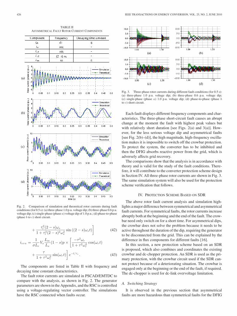
TABLE IIASYMMETRICAL FAULT ROTOR CURRENT COMPONENTS
Fig. 2. Comparison of simulation and theoretical rotor currents during faultconditions (for 0.5 s): (a) three-phase 1.0 p.u. voltage dip; (b) three-phase 0.6 p.u.voltage dip; (c) single-phase (phase a) voltage dip of 1.0 p.u.; (d) phase-to-phase(phase b to c) short circuit.
+τ 2r (2 − s)ωs
1 + τ 2r (2 − s)2ω2
s
sin ((2 − s)ωst)]
(42)
ivrn =1
σLrVs
Lm
Ls(1 − s)p ×
[−τ 2ωr
1 + τ 2ω2r
cos(ωr t)
+τ
1 + τ 2ω2r
sin(ωr t)]
e−t/τs . (43)
The components are listed in Table II with frequency anddecaying time constant characteristics.
The fault rotor currents are simulated in PSCAD/EMTDC tocompare with the analysis, as shown in Fig. 2. The generatorparameters are shown in the Appendix, and the RSC is controlledusing a voltage-regulating vector controller. The simulationshave the RSC connected when faults occur.
Fig. 3. Three-phase rotor currents during different fault conditions (for 0.5 s):(a) three-phase 1.0 p.u. voltage dip; (b) three-phase 0.6 p.u. voltage dip;(c) single-phase (phase a) 1.0 p.u. voltage dip; (d) phase-to-phase (phase bto c) short circuit.
Each fault displays different frequency components and char-acteristics. The three-phase short-circuit fault causes an abruptchange at the moment the fault with highest peak values butwith relatively short duration [see Figs. 2(a) and 3(a)]. How-ever, for the less serious voltage dip and asymmetrical faults[see Fig. 2(b)–(d)], the high magnitude, high-frequency oscilla-tion makes it is impossible to switch off the crowbar protection.To protect the system, the converter has to be inhibited andthen the DFIG absorbs reactive power from the grid, which isadversely affects grid recovery.
The comparisons show that the analysis is in accordance withtheory and is valid for the study of the fault conditions. There-fore, it will contribute to the converter protection scheme designin Section IV. All three-phase rotor currents are shown in Fig. 3.The same simulation system will also be used for the protectionscheme verification that follows.
IV. PROTECTION SCHEME BASED ON SDR
The above rotor fault current analysis and simulation high-lights a major difference between symmetrical and asymmetricalfault currents. For symmetrical faults, the rotor currents increaseabruptly both at the beginning and the end of the fault. The crow-bar need only switch on for a short time. For asymmetrical dips,the crowbar does not solve the problem because it needs to beactive throughout the duration of the dip, requiring the generatorto be disconnected from the grid. This can be explained by thedifference in flux components for different faults [16].
In this section, a new protection scheme based on an SDRis proposed, which also combines and coordinates the existingcrowbar and dc-chopper protection. An SDR is used as the pri-mary protection, with the crowbar circuit used if the SDR can-not protect because of a deteriorating situation. The crowbar isengaged only at the beginning or the end of the fault, if required.The dc-chopper is used for dc-link overvoltage limitation.
A. Switching Strategy
It is observed in the previous section that asymmetricalfaults are more hazardous than symmetrical faults for the DFIG
YANG et al.: SERIES-DYNAMIC-RESISTOR-BASED CONVERTER PROTECTION SCHEME 427
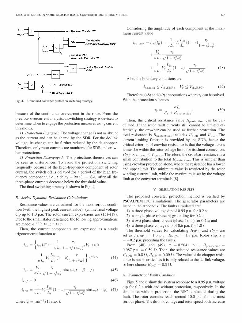
Fig. 4. Combined converter protection switching strategy.
because of the continuous overcurrent in the rotor. From theprevious overcurrent analysis, a switching strategy is devised todetermine when to engage the protection measures using currentthresholds.
1) Protection Engaged: The voltage change is not as abruptas the current and can be shared by the SDR. For the dc-linkvoltage, its change can be further reduced by the dc-chopper.Therefore, only rotor currents are monitored for SDR and crow-bar protections.
2) Protection Disengaged: The protections themselves canbe seen as disturbances. To avoid the protections switchingfrequently because of the high-frequency component of rotorcurrent, the switch off is delayed for a period of the high fre-quency component, i.e., t delay = 2π/(1 − s)ωs after all thethree-phase currents decrease below the threshold value.
The final switching strategy is shown in Fig. 4.
B. Series-Dynamic-Resistance Calculations
Resistance values are calculated for the most serious condi-tion (with the highest peak current value): symmetrical voltagedip up to 1.0 p.u. The rotor current expressions are (15)–(19).Due to the small stator resistance, the following approximationsare made: e−t/τs ≈ 1; τ ≈ τr .
Then, the current components are expressed as a singletrigonometric function as
idc =
ira(t−0 ) − 1σLr
τr
1 + τ 2r (sωs)
2 Vr cos β
− 1σLr
VsLm
Ls(1 − s)
τ
1 + τ 2ω2r
e−t/τr (44)
ivr =Vr
σLr
τr√1 + τ 2
r ω2r
sin(sωst + β + ϕ) (45)
ivrf = 0 (46)
ivrn =1
σLrVs
Lm
Ls(1 − s)
τr√1 + τ 2
r ω2r
sin(ωr t + ϕ) (47)
where ϕ = tan−1 (1/τrωr ).
Considering the amplitude of each component at the maxi-mum current value
ira,max = ira(t−0 ) − 1σLr
VsLm
Ls(1 − s)
τr
1 + τ 2r ω2
r
+Vr
σLr
τr√1 + τ 2
r ω2r
+1
σLrVs
Lm
Ls(1 − s)
τr√1 + τ 2
r ω2r
. (48)
Also, the boundary conditions are
ira,max ≤ Ith SDR , Vr ≤ Vth RSC . (49)
Therefore, (48) and (49) are equations where τr can be solved.With the protection schemes
τr =σLr
Rr + Rprotection. (50)
Then, the critical resistance value Rprotection can be cal-culated. If the rotor fault currents still cannot be limited ef-fectively, the crowbar can be used as further protection. Thetotal resistance is Rprotection , includes RSDR and RC B . Thecurrent-limiting function is provided by the SDR, hence thecritical criterion of crowbar resistance is that the voltage acrossit must be within the rotor voltage limit, for its shunt connection:RC B × ir,max ≤ Vr,max . Therefore, the crowbar resistance is asmall contribution to the total Rprotection . This is simpler thanusing crowbar protection alone, where the resistance has a lowerand upper limit. The minimum value is restricted by the rotorwinding current limit, while the maximum is set by the voltagelimit at the converter terminals [8].
V. SIMULATION RESULTS
The proposed converter protection method is verified byPSCAD/EMTDC simulations. The generator parameters arelisted in the Appendix. The faults simulated are:
1) a three-phase voltage dip of 0.95 p.u. for 0.2 s;2) a single-phase (phase a) grounding for 0.2 s;3) a two-phase short circuit (phase b to c) for 0.2 s; and4) a three-phase voltage dip of 0.6 p.u. for 1.0 s.The threshold values for calculating RSDR and RC B are
set as Ith SDR = 1.5 p.u., Ith C B = 1.8 p.u. Rotor slip is s= −0.2 p.u. preceding the faults.
From (48) and (49), τr = 0.2041 p.u., Rprotection =0.987 p.u. = 0.59 Ω. Then, the selected resistance values areRSDR = 0.5 Ω, RC B = 0.09 Ω. The value of dc-chopper resis-tance is not so critical as it is only related to the dc-link voltage,so here choose RdcC = 0.5 Ω.
A. Symmetrical Fault Condition
Figs. 5 and 6 show the system response to a 0.95 p.u. voltagedip for 0.2 s with and without protection, respectively. In thesimulation without protection, the RSC is blocked during thefault. The rotor currents reach around 10.0 p.u. for the mostserious phase. The dc-link voltage and rotor speed both increase
428 IEEE TRANSACTIONS ON ENERGY CONVERSION, VOL. 25, NO. 2, JUNE 2010
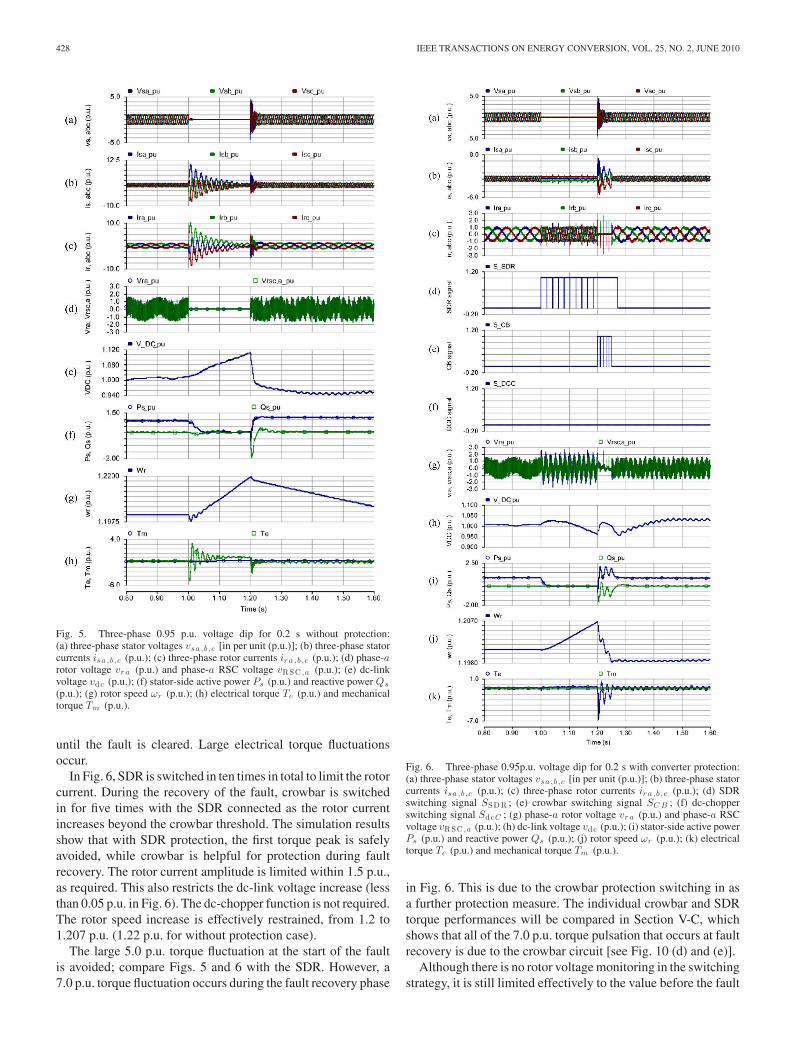
Fig. 5. Three-phase 0.95 p.u. voltage dip for 0.2 s without protection:(a) three-phase stator voltages vsa ,b ,c [in per unit (p.u.)]; (b) three-phase statorcurrents isa ,b ,c (p.u.); (c) three-phase rotor currents ir a ,b ,c (p.u.); (d) phase-arotor voltage vr a (p.u.) and phase-a RSC voltage vRSC ,a (p.u.); (e) dc-linkvoltage vdc (p.u.); (f) stator-side active power Ps (p.u.) and reactive power Qs
(p.u.); (g) rotor speed ωr (p.u.); (h) electrical torque Te (p.u.) and mechanicaltorque Tm (p.u.).
until the fault is cleared. Large electrical torque fluctuationsoccur.
In Fig. 6, SDR is switched in ten times in total to limit the rotorcurrent. During the recovery of the fault, crowbar is switchedin for five times with the SDR connected as the rotor currentincreases beyond the crowbar threshold. The simulation resultsshow that with SDR protection, the first torque peak is safelyavoided, while crowbar is helpful for protection during faultrecovery. The rotor current amplitude is limited within 1.5 p.u.,as required. This also restricts the dc-link voltage increase (lessthan 0.05 p.u. in Fig. 6). The dc-chopper function is not required.The rotor speed increase is effectively restrained, from 1.2 to1.207 p.u. (1.22 p.u. for without protection case).
The large 5.0 p.u. torque fluctuation at the start of the faultis avoided; compare Figs. 5 and 6 with the SDR. However, a7.0 p.u. torque fluctuation occurs during the fault recovery phase
Fig. 6. Three-phase 0.95p.u. voltage dip for 0.2 s with converter protection:(a) three-phase stator voltages vsa ,b ,c [in per unit (p.u.)]; (b) three-phase statorcurrents isa ,b ,c (p.u.); (c) three-phase rotor currents ir a ,b ,c (p.u.); (d) SDRswitching signal SSDR ; (e) crowbar switching signal SC B ; (f) dc-chopperswitching signal SdcC ; (g) phase-a rotor voltage vr a (p.u.) and phase-a RSCvoltage vRSC ,a (p.u.); (h) dc-link voltage vdc (p.u.); (i) stator-side active powerPs (p.u.) and reactive power Qs (p.u.); (j) rotor speed ωr (p.u.); (k) electricaltorque Te (p.u.) and mechanical torque Tm (p.u.).
in Fig. 6. This is due to the crowbar protection switching in asa further protection measure. The individual crowbar and SDRtorque performances will be compared in Section V-C, whichshows that all of the 7.0 p.u. torque pulsation that occurs at faultrecovery is due to the crowbar circuit [see Fig. 10 (d) and (e)].
Although there is no rotor voltage monitoring in the switchingstrategy, it is still limited effectively to the value before the fault
YANG et al.: SERIES-DYNAMIC-RESISTOR-BASED CONVERTER PROTECTION SCHEME 429
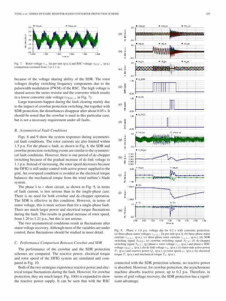
Fig. 7. Rotor voltage vr a [in per unit (p.u.)] and RSC voltage vRSC ,a (p.u.)comparison (zoomed from 1 to 1.1 s).
because of the voltage sharing ability of the SDR. The rotorvoltages display switching frequency components due to thepulsewidth modulation (PWM) of the RSC. The high voltage isshared across the series resistor and the converter which resultsin a lower converter side voltage (vRSC ,a in Fig. 7).
Large transients happen during the fault clearing mainly dueto the impact of crowbar protection switching, but together withSDR protection, the disturbances disappear after about 0.05 s. Itshould be noted that the crowbar is used in this particular case,but is not a necessary requirement under all faults.
B. Asymmetrical Fault Conditions
Figs. 8 and 9 show the system responses during asymmetri-cal fault conditions. The rotor currents are also limited within1.5 p.u. For the phase-a fault, as shown in Fig. 8, the SDR andcrowbar protection switching events are similar to the symmetri-cal fault conditions. However, there is one period of dc-chopperswitching because of the gradual increase of dc-link voltage to1.1 p.u. Instead of increasing, the rotor speed decreases becausethe DFIG is still under control with active power supplied to thegrid. An overspeed condition is avoided as the electrical torquebalances the mechanical torque from the wind turbine’s bladesystem.
The phase b to c short circuit, as shown in Fig. 9, in termsof fault current, is less serious than in the single-phase case.There is no need for both crowbar and dc-chopper operation.The SDR is effective in this condition. However, in terms ofstator voltage, this is more serious than for a single-phase fault.There are much larger power and electrical torque fluctuationsduring the fault. This results in gradual increase of rotor speed,from 1.20 to 1.21 p.u., but this is not serious.
The two asymmetrical conditions result in fluctuations afterstator voltage recovery. Although most of the variables are undercontrol, these fluctuations should be studied in more detail.
C. Performance Comparison Between Crowbar and SDR
The performance of the crowbar and the SDR protectionschemes are compared. The reactive power, electrical torqueand rotor speed of the DFIG system are simulated and com-pared in Fig. 10.
Both of the two strategies experience reactive power and elec-trical torque fluctuations during the fault. However, for crowbarprotection, they are much larger. Fig. 10(b) is expanded to showthe reactive power supply. It can be seen that with the RSC
Fig. 8. Phase a 1.0 p.u. voltage dip for 0.2 s with converter protection:(a) three-phase stator voltages vsa ,b ,c [in per unit (p.u.)]; (b) three-phase statorcurrents isa ,b ,c (p.u.); (c) three-phase rotor currents ir a ,b ,c (p.u.); (d) SDRswitching signal SSDR ; (e) crowbar switching signal SC B ; (f) dc-chopperswitching signal SdcC ; (g) phase-a rotor voltage vr a (p.u.) and phase-a RSCvoltage vRSC ,a (p.u.); (h) dc-link voltage vdc (p.u.); (i) stator-side active powerPs (p.u.) and reactive power Qs (p.u.); (j) rotor speed ωr (p.u.); (k) electricaltorque Te (p.u.) and mechanical torque Tm (p.u.).
connected with the SDR protection scheme, no reactive poweris absorbed. However, for crowbar protection, the asynchronousmachine absorbs reactive power, up to 0.2 p.u. Therefore, interms of grid voltage recovery, the SDR protection has a signif-icant advantage.
430 IEEE TRANSACTIONS ON ENERGY CONVERSION, VOL. 25, NO. 2, JUNE 2010
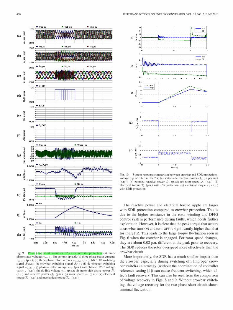
Fig. 9. Phase b to c short circuit for 0.2 s with converter protection: (a) three-phase stator voltages vsa ,b ,c [in per unit (p.u.)]; (b) three-phase stator currentsisa ,b ,c (p.u.); (c) three-phase rotor currents ir a ,b ,c (p.u.); (d) SDR switchingsignal SSDR ; (e) crowbar switching signal SC B ; (f) dc-chopper switchingsignal SdcC ; (g) phase-a rotor voltage vr a (p.u.) and phase-a RSC voltagevRSC ,a (p.u.); (h) dc-link voltage vdc (p.u.); (i) stator-side active power Ps
(p.u.) and reactive power Qs (p.u.); (j) rotor speed ωr (p.u.); (k) electricaltorque Te (p.u.) and mechanical torque Tm (p.u.).
Fig. 10. System response comparison between crowbar and SDR protections,voltage dip of 0.6 p.u. for 2 s: (a) stator-side reactive power Qs [in per unit(p.u.)]; (b) zoomed reactive power Qs (p.u.); (c) rotor speed ωr (p.u.); (d)electrical torque Te (p.u.) with CB protection; (e) electrical torque Te (p.u.)with SDR protection.
The reactive power and electrical torque ripple are largerwith SDR protection compared to crowbar protection. This isdue to the higher resistance in the rotor winding and DFIGcontrol system performance during faults, which needs furtherexploration. However, it is clear that the peak torque that occursat crowbar turn-ON and turn-OFF is significantly higher than thatfor the SDR. This leads to the large torque fluctuation seen inFig. 6 when the crowbar is engaged. For rotor speed changes,they are about 0.02 p.u. different at the peak prior to recovery.The SDR reduces the rotor overspeed more effectively than thecrowbar circuit.
More importantly, the SDR has a much smaller impact thanthe crowbar, especially during switching off. Improper crow-bar switch-OFF strategy (without the coordination of controllerreference setting [4]) can cause frequent switching, which af-fects fault recovery. This can also be seen from the comparisonof voltage recovery in Figs. 8 and 9. Without crowbar switch-ing, the voltage recovery for the two-phase short-circuit showsminimal fluctuation.
YANG et al.: SERIES-DYNAMIC-RESISTOR-BASED CONVERTER PROTECTION SCHEME 431
VI. APPLICATION DISCUSSIONS
A. Switch Time of the Bypass Switch
In practical applications, the switch time may be an issue,especially for serious fault protection and recovery when fastswitching response is required, e.g., some crowbar thyristorswitches cannot interrupt the current before zero-crossing [8].This will influence the protection performance. In the earliersimulations, switching times of the crowbar and SDR power-electronic switches are considered by disabling the interpolationin PSCAD/EMTDC. This solves the conflict between immediateswitching operation with simulation time step. The simulationtime step is set as 20 µs, so the actual switch time for IGBT is20 µs, which is enough for the IGBTs in applications (commonlyseveral microseconds [17]).
B. Switch Normal Operation Losses
The SDR is realized here by a power-electronic switch. How-ever, the bypass switch that is closed during normal opera-tion will produce additional losses, specifically device ON-statelosses. But compared to the stator-side braking resistor bypassswitches [13], this is far lower due to the lower power rating onthe rotor side.
VII. CONCLUSION
Converter protection is necessary for DFIG wind power gen-eration systems during fault conditions. In this paper, variousresistor protection schemes are reviewed. The purpose of anSDR is to avoid the frequent use of crowbar short-circuit, tomaximize the operation time of the RSC, and to reduce torquefluctuations during protection operation. The rotor currents dur-ing various fault conditions are discussed and current expres-sions are given to instruct the design of the protection scheme.Resistance calculations for the SDR and crowbar using the ex-pression of maximum rotor current are described.
The SDR can operate with the RSC control functioning. Forthe control of the grid-side converter to dc-link bus voltage, theresumption time can be shorter than for a system with normalactive crowbar protection. This is helpful for resuming normalcontrol and provides reactive power for grid voltage support.During this process, inspection of the reactive power, electricaltorque, and rotor speed fluctuations show that the proposedmethod enhances DFIG FRT capability.
APPENDIX
The generator parameters are shown in Table III.
TABLE IIIGENERATOR PARAMETERS
REFERENCES
[1] British Wind Energy Association. Offshore wind. (2009). [Online].Available: http://www.bwea.org/offshore/info.html
[2] The European Wind Energy Association. European statistics. (2009).[Online]. Available: http://www.ewea.org/index.php?id=1486
[3] P. J. Tavner, J. Xiang, and F. Spinato. (2007). Reliability analysis for windturbines. Wind Energy [Online]. 10, pp. 1–18. Available: http://www3.interscience.wiley.com/cgi-bin/fulltext/112701014/PDFSTART
[4] J. Morren and S. W. H. de Haan, “Ridethrough of wind turbines withdoubly-fed induction generator during a voltage dip,” IEEE Trans. EnergyConvers., vol. 20, no. 2, pp. 435–441, Jun. 2005.
[5] I. Erlich, J. Kretschmann, J. Fortmann, S. Mueller-Engelhardt, andH. Wrede, “Modeling of wind turbines based on doubly-fed inductiongenerators for power system stability studies,” IEEE Trans. Power Syst.,vol. 22, no. 3, pp. 909–919, Aug. 2007.
[6] D. Xiang, R. Li, P. J. Tavner, and S. Yang, “Control of a doubly fedinduction generator in a wind turbine during grid fault ride-through,”IEEE Trans. Energy Convers., vol. 21, no. 3, pp. 652–662, Sep. 2006.
[7] P. S. Flannery and G. Venkataramanan, “A fault tolerant doubly fed in-duction generator wind turbine using a parallel grid side rectifier andseries grid side converter,” IEEE Trans. Power Electron., vol. 23, no. 3,pp. 1126–1135, May 2008.
[8] J. Morren and S. W. H. de Haan, “Short-circuit current of wind turbineswith doubly fed induction generator,” IEEE Trans. Energy Convers.,vol. 22, no. 1, pp. 174–180, Mar. 2007.
[9] P. Zhou and Y. He, “Control strategy of an active crowbar for DFIG basedwind turbine under grid voltage dips,” presented at the Int. Conf. Electr.Mach. Syst. 2007, Seoul, Korea, Oct. 8–11, 2007.
[10] M. Rodrıguez, G. Abad, I. Sarasola, and A. Gilabert, “Crowbar controlalgorithms for doubly fed induction generator during voltage dips,” pre-sented at the 11th Eur. Conf. Power Electron. Appl., Dresden, Germany,Sep. 11–14, 2005.
[11] I. Erlich, H. Wrede, and C. Feltes, “Dynamic behavior of DFIG-basedwind turbines during grid faults,” presented at the Power Convers. Conf.,Nagoya, Japan, Apr. 2–5, 2007.
[12] J. F. Conroy and R. Watson, “Low-voltage ride-through of a full con-verter wind turbine with permanent magnet generator,” IET Renew. PowerGener., vol. 1, no. 3, pp. 182–189, 2007.
[13] A. Causebrook, D. J. Atkinson, and A. G. Jack, “Fault ride-through oflarge wind farms using series dynamic braking resistors,” IEEE Trans.Power Syst., vol. 22, no. 3, pp. 966–975, Aug. 2007.
[14] J. Lopez, P. Sanchis, X. Roboam, and L. Marroyo, “Dynamic behaviorof the doubly fed induction generator during three-phase voltage dips,”IEEE Trans. Energy Convers., vol. 22, no. 3, pp. 709–717, Sep. 2007.
[15] M. S. Vicatos and J. A. Tegopoulos, “Transient state analysis of a doubly-fed induction generator under three phase short circuit,” IEEE Trans.Energy Convers., vol. 6, no. 1, pp. 62–68, Mar. 1991.
[16] J. Lopez, E. Gubıa, P. Sanchis, X. Roboam, and L. Marroyo, “Windturbines based on doubly fed induction generator under asymmetricalvoltage dips,” IEEE Trans. Energy Convers., vol. 23, no. 1, pp. 321–330,Mar. 2008.
[17] S. Castagno, R. D. Curry, and E. Loree, “Analysis and comparison of afast turn-on series IGBT stack and high-voltage-rated commercial IGBTs,”IEEE Trans. Plasma Sci., vol. 34, no. 5, pp. 1692–1696, Oct. 2006.
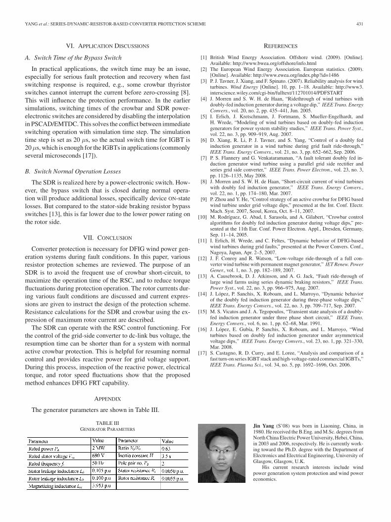
Jin Yang (S’08) was born in Liaoning, China, in1980. He received the B.Eng. and M.Sc. degrees fromNorth China Electric Power University, Hebei, China,in 2003 and 2006, respectively. He is currently work-ing toward the Ph.D. degree with the Department ofElectronics and Electrical Engineering, University ofGlasgow, Glasgow, U.K.
His current research interests include windpower generation system protection and wind powereconomics.

432 IEEE TRANSACTIONS ON ENERGY CONVERSION, VOL. 25, NO. 2, JUNE 2010
John E. Fletcher received the B.Eng. (first-class hon-ors) and Ph.D. degrees from Heriot-Watt University,Edinburgh, U.K., in 1991 and 1995, respectively, bothin electrical and electronic engineering.
Until 2007, he was with Heriot-Watt University.He is currently a Senior Lecturer with the Univer-sity of Strathclyde, Glasgow, U.K. His research in-terests include power electronics, drives and energyconversion, and manages research projects, includingdistributed and renewable integration, silicon-carbideelectronics, pulsed-power applications of power elec-
tronics, and the design and control of electrical machines.Dr. Fletcher is a Chartered Engineer in the U.K. and a Fellow of the Institu-
tion of Engineering and Technology.
John O’Reilly (M’81–SM’00) received the B.Sc.,Ph.D., and D.Sc. degrees in engineering from QueensUniversity, Belfast, U.K., in 1972, 1976, and 1985,respectively.
He is currently a Professor of control engineeringwith the Department of Electronics and Electrical En-gineering, University of Glasgow, Glasgow, U.K. Hisinterests include power system dynamics and controlwith renewable energy.