Embed Size (px)
Citation preview

422
Translation of the original instructions
FAAC S.p.A. Soc. UnipersonaleVia Calari, 10 - 40069 Zola Predosa BOLOGNA - ITALYTel. +39 051 61724 - Fax +39 051 09 57 820www.faac.it - www.faacgroup.com
© Copyright FAAC S.p.A. dal 2018. Tutti i diritti riservati.Nessuna parte di questo manuale può essere riprodotta, archiviata, distribuita a terzi né altrimenti copiata, in qualsiasi formato e con qualsiasi mezzo, sia esso elettronico, meccanico o tramite fotocopia, senza il preventivo consenso scritto di FAAC S.p.A.Tutti i nomi e i marchi citati sono di proprietà dei rispettivi fabbricanti.I clienti possono effettuare copie per esclusivo utilizzo proprio.Questo manuale è stato pubblicato nel 2018.
© Copyright FAAC S.p.A. from 2018. All rights reserved.No part of this manual may be reproduced, archived, distributed to third parties nor copied in any other way, in any format and with any means, be it electronic, mechanical or by photocopying, without prior written authorisation by FAAC S.p.A.All names and trademarks mentioned are the property of their respective manu-facturers.Customers may make copies exclusively for their own use.This manual was published in 2018.
© Copyright FAAC S.p.A. depuis 2018. Tous droits réservés.Aucune partie de ce manuel ne peut être reproduite, archivée ou distribuée à des tiers ni copiée, sous tout format et avec tout moyen, qu’il soit électronique, mécanique ou par photocopie, sans le consentement écrit préalable de FAAC S.p.A.Tous les noms et les marques cités sont la propriété de leurs fabricants respectifs.Les clients peuvent faire des copies pour leur usage exclusif.Ce manuel a été publié en 2018.
© Copyright FAAC S.p.A. ab dem 2018. Alle Rechte vorbehalten.Kein Teil dieses Handbuchs darf reproduziert, gespeichert, an Dritte weitergegeben oder sonst auf eine beliebige Art in einem beliebigen Format und mit beliebigen Mitteln kopiert werden, weder mit elektronischen, noch mechanischen oder durch Fotokopieren, ohne die Genehmigung von FAAC S.p.A.Alle erwähnten Namen und Marken sind Eigentum der jeweiligen Hersteller.Die Kunden dürfen nur für den Eigengebrauch Kopien anfertigen.Dieses Handbuch wurde 2018 veröffentlicht.
© Copyright FAAC S.p.A. del 2018. Todos los derechos están reservados.No puede reproducirse, archivarse, distribuirse a terceros ni copiarse de ningún modo, ninguna parte de este manual, con medios mecánicos o mediante fotocopia, sin el permiso previo por escrito de FAAC S.p.A.Todos los nombre y las marcas citadas son de propiedad de los respectivos fabricantes.Los clientes pueden realizar copias para su uso exclusivo.Este manual se ha publicado en 2018.
© Copyright FAAC S.p.A. van 2018. Alle rechten voorbehouden.Niets uit deze handleiding mag gereproduceerd, gearchiveerd, aan derden openbaar gemaakt of op andere wijze gekopieerd worden, in om het even welke vorm en met geen enkel middel, noch elektronisch, mechanisch of via fotokopiëren, zonder schrfitelijke toestemming vooraf van FAAC S.p.A.Alle vermelde namen en merken zijn eigendom van de respectievelijke fabrikanten.De klanten mogen kopieën maken die enkel voor eigen gebruik bestemd zijn.Dez handleiding werd in 2018 gepubliceerd.

422 1 732870 - Rev.C
Tran
slatio
n of
the
orig
inal
inst
ruct
ions
ENGLISH
Tran
slatio
n of
the
orig
inal
inst
ruct
ions
ENGLISH
EU DECLARATION OF CONFORMITY
The Manufacturer
Company name: FAAC S.p.A. Soc. Unipersonale
Address: Via Calari, 10 - 40069 Zola Predosa BOLOGNA - ITALY
hereby declares on his sole responsibility that the following products:
Description: Swing gate actuator
Models: 422
comply with the following applicable EU legislations:
2014/30/EU2011/65/EU
Furthermore, the following harmonised standards have been applied:
EN61000-6-2:2005EN61000-6-3:2007 + A1:2011
Bologna, Italy, 01-08-2018 CEOA. Marcellan
DECLARATION OF INCORPORATION FOR PARTLY COMPLETED MACHINERY(2006/42/EC ANNEX II P.1, B)
Manufacturer and person authorised to prepare the relevant technical documentation
Company name: FAAC S.p.A. Soc. Unipersonale
Address: Via Calari, 10 - 40069 Zola Predosa BOLOGNA - ITALY
hereby declares that for the partly completed machinery:
Description: Swing gate actuator
Model: 422
The essential requirements of the Machinery Directive 2006/42/EC (including all applicable amendments) that have been applied and fulfilled are as follows:
1.1.2, 1.1.3, 1.1.5, 1.1.6, 1.3.1, 1.3.2, 1.3.4, 1.5.1, 1.5.3, 1.5.5, 1.5.6, 1.5.8, 1.5.13, 1.6.1, 1.6.4, 1.7.2, 1.7.3, 1.7.4.
and that the relevant technical documentation has been compiled in compliance with part B of Annex VII. Furthermore, the following harmonised standards have been applied:
EN12100:2010EN13849-1:2015EN13849-2:2012
Other standards applied:EN 12453:2017
And also undertakes to transmit, in response to a reasoned request by the national au-thorities, relevant information on the partly completed machinery by mail or e-mail.Finally, the manufacturer declares that the above-mentioned partly completed machinery must not be put into service until the final machine in which it is to be incorporated has been declared compliant with the requirements of the above-mentioned Machinery Directive 2006/42/EC.
Bologna, Italy, 01-08-2018 CEOA. Marcellan

422 2 732870 - Rev.C
CONTENTSEU Declaration of conformity . . . . . . . . . . . . . . . . . . . . . . . . . . . . . . . . . . . 1Declaration of incorporation for partly completed machinery 1
1. INTRODUCTION TO THE INSTRUCTION MANUAL . . . . . . . . . . . 31.1 Meaning of the symbols used . . . . . . . . . . . . . . . . . . . . . . . . . . . . . . . . . . . 3
2. SAFETY RECOMMENDATIONS . . . . . . . . . . . . . . . . . . . . . . . . . . . . . . . . . . 42.1 Installer safety . . . . . . . . . . . . . . . . . . . . . . . . . . . . . . . . . . . . . . . . . . . . . . . . . . . . 42.2 Transport and storage . . . . . . . . . . . . . . . . . . . . . . . . . . . . . . . . . . . . . . . . . . . . 42.3 Unpacking and handling . . . . . . . . . . . . . . . . . . . . . . . . . . . . . . . . . . . . . . . . 5
Vent closure . . . . . . . . . . . . . . . . . . . . . . . . . . . . . . . . . . . . . . . . . . . . . . . . . . . . . . . 52.4 Disposal of the product . . . . . . . . . . . . . . . . . . . . . . . . . . . . . . . . . . . . . . . . . . 5
3. 422 . . . . . . . . . . . . . . . . . . . . . . . . . . . . . . . . . . . . . . . . . . . . . . . . . . . . . . . . . . . . . . . . . . . . 63.1 Intended use . . . . . . . . . . . . . . . . . . . . . . . . . . . . . . . . . . . . . . . . . . . . . . . . . . . . . . 63.2 Limitations of use . . . . . . . . . . . . . . . . . . . . . . . . . . . . . . . . . . . . . . . . . . . . . . . . . 63.3 Unauthorised use . . . . . . . . . . . . . . . . . . . . . . . . . . . . . . . . . . . . . . . . . . . . . . . . . 63.4 Emergency use . . . . . . . . . . . . . . . . . . . . . . . . . . . . . . . . . . . . . . . . . . . . . . . . . . . . 63.5 Product identification . . . . . . . . . . . . . . . . . . . . . . . . . . . . . . . . . . . . . . . . . . . . 6
Indications on the product . . . . . . . . . . . . . . . . . . . . . . . . . . . . . . . . . . . . . . 63.6 Technical characteristics . . . . . . . . . . . . . . . . . . . . . . . . . . . . . . . . . . . . . . . . . 73.7 Component identification . . . . . . . . . . . . . . . . . . . . . . . . . . . . . . . . . . . . . . . 8
Components supplied . . . . . . . . . . . . . . . . . . . . . . . . . . . . . . . . . . . . . . . . . . . 83.8 Dimensions . . . . . . . . . . . . . . . . . . . . . . . . . . . . . . . . . . . . . . . . . . . . . . . . . . . . . . . . 93.9 Manual operation. . . . . . . . . . . . . . . . . . . . . . . . . . . . . . . . . . . . . . . . . . . . . . . . . 9
Releasing the actuator (6 ) . . . . . . . . . . . . . . . . . . . . . . . . . . . . . . . . . . . 9Restoring operation (7 ) . . . . . . . . . . . . . . . . . . . . . . . . . . . . . . . . . . . . . . 9
4. INSTALLATION REQUIREMENTS . . . . . . . . . . . . . . . . . . . . . . . . . . . . . . 104.1 Mechanical requirements . . . . . . . . . . . . . . . . . . . . . . . . . . . . . . . . . . . . . . . 104.2 Electrical system . . . . . . . . . . . . . . . . . . . . . . . . . . . . . . . . . . . . . . . . . . . . . . . . . 104.3 Example system. . . . . . . . . . . . . . . . . . . . . . . . . . . . . . . . . . . . . . . . . . . . . . . . . . 11
5. INSTALLATION . . . . . . . . . . . . . . . . . . . . . . . . . . . . . . . . . . . . . . . . . . . . . . . . . . . 11Tools required . . . . . . . . . . . . . . . . . . . . . . . . . . . . . . . . . . . . . . . . . . . . . . . . . . . . 11
5.1 Determining the position of the rear bracket . . . . . . . . . . . . . . . . 125.2 Installing the rear bracket . . . . . . . . . . . . . . . . . . . . . . . . . . . . . . . . . . . . . . 13
Steel pillar . . . . . . . . . . . . . . . . . . . . . . . . . . . . . . . . . . . . . . . . . . . . . . . . . . . . . . . . 13Masonry pillar with plate to embed . . . . . . . . . . . . . . . . . . . . . . . . . . . 13Masonry pillar with screw-on plate . . . . . . . . . . . . . . . . . . . . . . . . . . . . 13
5.3 Installing the fork and joint . . . . . . . . . . . . . . . . . . . . . . . . . . . . . . . . . . . . . 14Installing the rear Fork . . . . . . . . . . . . . . . . . . . . . . . . . . . . . . . . . . . . . . . . . . 14Installing the front Joint . . . . . . . . . . . . . . . . . . . . . . . . . . . . . . . . . . . . . . . . 14
5.4 Fastening the actuator . . . . . . . . . . . . . . . . . . . . . . . . . . . . . . . . . . . . . . . . . . 145.5 Installing the casing . . . . . . . . . . . . . . . . . . . . . . . . . . . . . . . . . . . . . . . . . . . . . 155.6 Installing the power cable . . . . . . . . . . . . . . . . . . . . . . . . . . . . . . . . . . . . . . 15
6. START-UP. . . . . . . . . . . . . . . . . . . . . . . . . . . . . . . . . . . . . . . . . . . . . . . . . . . . . . . . . . 166.1 Removing the breather screw . . . . . . . . . . . . . . . . . . . . . . . . . . . . . . . . . . 166.2 Adjusting the force (By-Pass) . . . . . . . . . . . . . . . . . . . . . . . . . . . . . . . . . . . 16
7. PUTTING INTO SERVICE . . . . . . . . . . . . . . . . . . . . . . . . . . . . . . . . . . . . . . . . 177.1 Final checks . . . . . . . . . . . . . . . . . . . . . . . . . . . . . . . . . . . . . . . . . . . . . . . . . . . . . . 177.2 Final operations . . . . . . . . . . . . . . . . . . . . . . . . . . . . . . . . . . . . . . . . . . . . . . . . . . 17
8. ACCESSORIES . . . . . . . . . . . . . . . . . . . . . . . . . . . . . . . . . . . . . . . . . . . . . . . . . . . . . 17
9. MAINTENANCE . . . . . . . . . . . . . . . . . . . . . . . . . . . . . . . . . . . . . . . . . . . . . . . . . . . 189.1 Routine maintenance . . . . . . . . . . . . . . . . . . . . . . . . . . . . . . . . . . . . . . . . . . . 189.2 Operational problems . . . . . . . . . . . . . . . . . . . . . . . . . . . . . . . . . . . . . . . . . . . 18
10. INSTRUCTIONS FOR USE . . . . . . . . . . . . . . . . . . . . . . . . . . . . . . . . . . . . . 2010.1 Safety recommendations. . . . . . . . . . . . . . . . . . . . . . . . . . . . . . . . . . . . . . 2010.2 Emergency use . . . . . . . . . . . . . . . . . . . . . . . . . . . . . . . . . . . . . . . . . . . . . . . . . 2010.3 Manual operation . . . . . . . . . . . . . . . . . . . . . . . . . . . . . . . . . . . . . . . . . . . . . . 20
Releasing the actuator (29 ) . . . . . . . . . . . . . . . . . . . . . . . . . . . . . . . . 20Restoring operation (30 ) . . . . . . . . . . . . . . . . . . . . . . . . . . . . . . . . . . . 20Adjusting the force (By-Pass) . . . . . . . . . . . . . . . . . . . . . . . . . . . . . . . . . . . 23
TABLES 1 Symbols: notes and warnings on the instructions . . . . . . . . . . . . . 3 2 Symbols: safety signs and symbols (EN ISO 7010) . . . . . . . . . . . . . 3 3 Symbols: Personal Protective Equipment . . . . . . . . . . . . . . . . . . . . . . 3 4 Technical data . . . . . . . . . . . . . . . . . . . . . . . . . . . . . . . . . . . . . . . . . . . . . . . . . . . . . 7 5 Symbols: tools (type and size) . . . . . . . . . . . . . . . . . . . . . . . . . . . . . . . . . 11 6 Distances 422 Standard . . . . . . . . . . . . . . . . . . . . . . . . . . . . . . . . . . . . . . . . 12 7 Distances 422 PED. . . . . . . . . . . . . . . . . . . . . . . . . . . . . . . . . . . . . . . . . . . . . . . 12 8 Troubleshooting. . . . . . . . . . . . . . . . . . . . . . . . . . . . . . . . . . . . . . . . . . . . . . . . . 18 9 Scheduled maintenance . . . . . . . . . . . . . . . . . . . . . . . . . . . . . . . . . . . . . . . 19 10 422 standard, flow rate 0.75 l/min . . . . . . . . . . . . . . . . . . . . . . . . . . . . 21 11 422 standard, flow rate 1.0 l/min . . . . . . . . . . . . . . . . . . . . . . . . . . . . . . 21 12 422 standard, flow rate 1.5 l/min . . . . . . . . . . . . . . . . . . . . . . . . . . . . . . 21 13 422 PED. flow rate 1.5 l/min . . . . . . . . . . . . . . . . . . . . . . . . . . . . . . . . . . . . 22 14 Distances 422 Standard . . . . . . . . . . . . . . . . . . . . . . . . . . . . . . . . . . . . . . . . 23 15 Distances 422 PED. . . . . . . . . . . . . . . . . . . . . . . . . . . . . . . . . . . . . . . . . . . . . . . 23
ADDENDUM 1 Limits of use of the 422 in relation to wind . . . . . . . . . . . . . . . . . . 21 2 Outward opening applications . . . . . . . . . . . . . . . . . . . . . . . . . . . . . . . . 23

422 3 732870 - Rev.C
Tran
slatio
n of
the
orig
inal
inst
ruct
ions
ENGLISH
Tran
slatio
n of
the
orig
inal
inst
ruct
ions
ENGLISH
1. INTRODUCTION TO THE INSTRUCTION MANUAL
1 Symbols: notes and warnings on the instructions
FWARNING ELECTRIC SHOCK HAZARD - The operation or stage described must be performed following the supplied instructions and applicable safety regulations.
!WARNING, PERSONAL INJURY HAZARD OR RISK OF DAMAGE TO COMPO-NENTS - The procedure or step described must be carried out following the instructions provided and according to the applicable safety regulations.
i WARNING - Details and specifications which must be respected in order to ensure that the system operates correctly.
RECYCLING and DISPOSAL - Components and structural materials, batteries and electronic components must not be disposed of together with household waste. They must be taken to authorised disposal and recycling centres.
For manual lifting, there should be 1 person for every 20 kg to be lifted.
PAGE E.g.: 6 see Page 6.
FIGURE E.g.: 1 -3 see Figure 1 - detail 3.
TABLE E.g.: 1 see Table 1.
§ CHAPTER/SECTION E.g.: §1.1 see section 1.1.
APPENDIX E.g.: 1 see Appendix 1.
2 Symbols: safety signs and symbols (EN ISO 7010)
GENERIC HAZARDPersonal injury hazard or risk of damage to components.
ELECTROCUTION HAZARDRisk of electric shock from live parts.
CRUSHING HAZARDRisk of crushing to the hands/feet due to the presence of heavy parts.
CUTTING/AMPUTATION/PIERCING HAZARDCutting hazard due to the presence of sharp components or the use of pointed/sharp tools (drill).
RISK OF IMPACT/CRUSHINGRisk of impact or crushing due to moving parts.
COLLISION WITH FORKLIFT TRUCKS HAZARDRisk of collision/impact with forklift trucks.
1.1 MEANING OF THE SYMBOLS USED
This manual provides the correct procedures and requirements for installing 422 and maintaining it in a safe condition.When drafting the manual, the results of the risk assessment con-ducted by FAAC S.p.A. on the entire product life cycle have been taken into account in order to implement effective risk reduction measures.The following stages of the life cycle of the product have been con-sidered:
- Delivery/handling - Assembly and installation - Set-up and commissioning - Operation - Maintenance/troubleshooting - Disposal at the end of the product’s life cycle
Risks arising from installation and using the product have been taken into consideration; these include:
- Risks for the installation/maintenance technician (technical personnel)
- Risks for the user of the automation system - Risks to product integrity (damage)
In Europe, the automation of a gate falls under the Machinery Directive 2006/42/EC and the corresponding harmonised standards. Anyone automating a gate (new or existing) is classified as the Manufacturer of the Machine. They are therefore required by law, among other things, to carry out a risk analysis of the machine (automatic gate in its entirety) and take protective measures to fulfil the essential safety requirements specified in Annex I of the Machinery Directive.FAAC S.p.A. recommends that you always comply with the EN 12453 standard and in particular that you adopt the safety criteria and de-vices indicated, without exception, including the dead-man function.This manual also contains general information and guidelines, which are purely illustrative and not exhaustive, in order to facilitate the ac-tivities carried out by the Manufacturer of the Machine in all respects with regard to carrying out the risk analysis and drafting the instruc-tions for use and maintenance of the machine. It should be clearly understood that FAAC S.p.A. accepts no liability for the reliability and/ or completeness of the above instructions. As such, the manufacturer of the machine must carry out all the activities required by the Machi-nery Directive and the corresponding harmonised standards on the basis of the actual condition of the locations and structures where the product 422 will be installed, prior to commissioning the machine. These activities include the analysis of all the risks associated with the machine and subsequent implementation of all safety measures intended to fulfil the essential safety requirements.This manual contains references to European standards. The au-tomation of a gate must fully comply with any laws, standards and regulations applicable in the country where installation will take place.
Li Unless otherwise specified, the measurements provided in the instructions are in mm.
3 Symbols: Personal Protective EquipmentPersonal protective equipment must be worn to protect against hazards (e.g. crushing, cutting, shearing etc.):
Obligation to wear safety footwear.
Obligation to wear mask/goggles to protect the eyes from the risk of frag-ments due to the use of drill or welder.
Obligation to wear work gloves.
Obligation to wear work clothes without parts that could become caught in moving parts.

422 4 732870 - Rev.C
2. SAFETY RECOMMENDATIONS
Installation activities require special work conditions to reduce to the minimum the risks of accidents and serious damage. Furthermore, the suitable precautions must be taken to prevent risks of injury to persons or damage.
! The installer must be in good physical and mental condition, aware of and responsible for the hazards that may be generated when using the product.The work area must be kept tidy and must not be left unattended.Do not wear clothes or accessories (scarves, bracelets, etc.) that may get caught in moving parts.Always wear the personal protective equipment recommended for the type of activity to be carried out.The required level of workplace lighting must be equal to at least 200 lux.Operate CE marked machinery and equipment in compliance with the manufacturer's instructions. Use work instruments in good conditions.Use the transport and lifting equipment recommended in the instructions manual.Use safety-compliant portable ladders of adequate size, fitted with anti-slip devices at the top and bottom, equipped with retainer hooks.
2.1 INSTALLER SAFETY
This product is placed onto the market as “partly completed machinery”, therefore it cannot be commissioned until the machine in which it will be incorporated has been identified and declared to conform to the Machinery Directive 2006/42/EC by the actual Manufacturer.
! Incorrect installation and/or incorrect use of the product might cause serious harm to people. Read and comply with all the instructions before starting any activity on the product. Keep these instructions for future reference.Perform installation and other activities adhering to the sequences provided in the instructions manual.Always comply with all the requirements contained in the instructions and warning tables at the beginning of the paragraphs. Always comply with the safety recommendations.Only the installer and/or maintenance technician is authorised to work on the automation components. Do not modify the original components in any way.Close off the work site (even temporarily) and prevent access/transit. EC countries must comply with the legislation that transposes the European Construction Site Directive 92/57/EC.
The installer is responsible for the installation/testing of the automation and for completing the Register of the system.The installer must prove or declare to possess technical and professional proficiency to perform installation, testing and maintenance activi-ties according to the requirements in these instructions.
2.2 TRANSPORT AND STORAGE
SINGLE PACKAGERISKS
PERSONAL PROTECTIVE EQUIPMENT
! Follow the instructions on the packaging during handling.Use a forklift or pallet truck, following safety regulations to avoid the risk of impacts or collisions.
! Follow the instructions on the packaging during handling.
PALLETISED SUPPLYRISKS
PERSONAL PROTECTIVE EQUIPMENT
STOCCAGGIOConservare il prodotto nel proprio imballo originale, in ambienti chiu-si, asciutti, al riparo dal sole e privi di polvere e sostanze aggressive. Proteggere da sollecitazioni meccaniche. In caso di stoccaggio oltre 3 mesi, controllare periodicamente le condizioni dei componenti e dell’imballo.
- Temperatura di stoccaggio: da 5 °C a 30 °C. - Percentuale di umidità: da 30% a 70%.

1
2
422 5 732870 - Rev.C
1
2
3
5
4
67
3
Tran
slatio
n of
the
orig
inal
inst
ruct
ions
ENGLISH
Tran
slatio
n of
the
orig
inal
inst
ruct
ions
ENGLISH
1 4222 Casing3 Capacitor support4 Capacitor5 Instruction manual6 Power cable7 Installation accessories
2.3 UNPACKING AND HANDLINGRISKS
PERSONAL PROTECTIVE EQUIPMENT
1. Open the package and remove the contents.2. Check that all components are present and intact (1 ).3. Dispose of the packaging materials.
! The packaging materials (plastic, polystyrene etc.) must not be left within reach of children as they are potential sources of danger.
When you have finished with them, dispose of the packaging in the appropri-ate containers, as per applicable waste disposal regulations.
VENT CLOSURE
! The 422 is supplied with the vent hole closed with a screw and washer (2 ). Whenever the gate is handled, the vent must be closed to prevent oil leaking out.
2.4 DISPOSAL OF THE PRODUCT
After having dismantled the product, dispose of it in compliance with the current waste disposal regulations.
Components and structural materials, batteries and electronic components must not be disposed of together with household waste. They must be taken to authorised disposal and recycling centres.The oil must be gathered in a watertight container and given to an authorised disposal and recycling centre. Do not mix with other substances such as antifreeze or transmission fluids. Keep the used oil away from sources of heat and out of the children's reach. The fluid is not hazardous to health. In case of contact with eyes, skin or clothing, wash and rinse the affected parts.The technical data sheets of the fluids are available on request.

3
422 6 732870 - Rev.C
422
FAAC S.p.A. Soc. UnipersonaleVia Calari, 10 - 40069 Zola Predosa BOLOGNAItaly
••••••
••••••••••
•••••••••••
••••••
••••••
••••••
••••••
3. 422
3.1 INTENDED USEFAAC 422 series actuators are designed to operate horizontal move-ment swing gates for residential buildings / apartment complexes.One actuator must be installed for each leaf.The 422 is intended for installation on gates in areas that are acces-sible by people, the main purpose of which is to provide access for goods, vehicles and people.To move the gate manually, follow the Manual operation instructions.
! Any other use that is not expressly specified in these instructions is prohibited and could affect the integrity of the product and/or represent a source of danger.
3.3 UNAUTHORISED USE
3.2 LIMITATIONS OF USE
3.4 EMERGENCY USE
Sale codeProduct nameIDENTIFICATION NUMBER Month/year of production + progressive number for the month of productionExample: 0117 0001
produced in January 2017 S/N 1
In emergencies or if there is a fault, turn off the power supply to the automation. If the leaf can be moved safely by hand, use the MANUAL OPERATION mode; otherwise place the automation out of service until it has been reset/repaired. In the case of a breakdown, the automation must be reset/repaired exclusively by the installer/maintenance technician.
- Uses other than the intended use are prohibited. - It is prohibited to install the automation system outside of the
limits specified in the Technical Data and Installation Require-ments sections.
- It is forbidden to use 422 in a constructional configuration other than the one provided by the manufacturer.
- No component part of the product may be modified. - It is prohibited to install the automation system on escape routes. - It is prohibited to install the automation system to create fire
doors. - It is prohibited to install the automation system in environments
in which there is a risk of explosion and/or fire: the presence of flammable gases or fumes is a serious safety hazard.
- It is prohibited to power the system with energy sources other than those specified.
- It is prohibited to integrate commercial systems and/or equipment other than those specified, or use them for purposes not intended and authorised by their respective manufacturers.
- Do not allow water jets of any type or size to come into direct contact with the actuator.
- Do not expose the actuator to corrosive chemicals or atmospheric agents.
- It is prohibited to use and/or install accessories which have not been specifically approved by FAAC S.p.A.
- It is prohibited to use the automation system before performing commissioning.
- It is prohibited to use the automation system in the presence of faults which could compromise safety.
- It is prohibited to use the automation system with the fixed and/or mobile guards removed or altered.
- Do not use the automation system unless the area of operation is free of persons, animals or objects.
- Do not enter/remain in the area of operation of the automation system while it is moving.
- Do not try to prevent the movement of the automation system. - Do not climb on, hold onto or let yourself be pulled by the
leaf. Do not climb onto the actuator. - Do not allow children to approach or play in the area of operation
of the automation system. - Do not allow the control devices to be used by anyone who is
not specifically authorised and trained to do so. - Do not allow the control devices to be used by children or persons
with mental and physical deficiencies unless they are supervised by an adult who is responsible for their safety.
! During manual operation, gently guide the leaf the whole way, do not push it and let it slide freely.
The leaf must fall within the dimensional and frequency of use limits indicated in the technical data.The presence of weather conditions such as snow, ice and strong wind, even occasional, could affect the correct operation of the automation, the integrity of the components and be a potential source of danger (see § Emergency use). The limitations of use of the 422 in wind are detailed in table Limits of use in relation to wind.422 is not designed to be a security (break-in protection) system.If there is a pedestrian access gate integrated in the leaf of the gate, the motorised movement must be disabled when the pedestrian gate is not in a safe position.The installation must be visible during the day and at night. If it is not, appropriate solutions must be provided to make the fixed and moving parts visible.The 422 must be connected to a FAAC electronic board as indicated in this manual ( Technical characteristics).Implementing the automation requires the installation of the neces-sary safety devices, identified by the installer through an appropriate risk assessment of the installation site.
3.5 PRODUCT IDENTIFICATION
INDICATIONS ON THE PRODUCT
Indicates the screw to be removed before putting into service. It is located on the rear flange of the actuator.
The product can be identified by the plate (see 3 ).

422 7 732870 - Rev.C
Tran
slatio
n of
the
orig
inal
inst
ruct
ions
ENGLISH
Tran
slatio
n of
the
orig
inal
inst
ruct
ions
ENGLISH
3.6 TECHNICAL CHARACTERISTICSThe 422 is a hydraulic actuator for swing gates. The system consists of an electric motor that displaces the oil in the hydraulic circuit by means of a pump and activates the piston (rod). The rod is fixed to the leaf in order to transmit movement.The 422 range of actuators includes different models according to:
The stroke of the rod in addition to the standard version, the actuators with a shorter rod (PED.) can be installed even on small gates.Pump flow rate the electric motor and pump assembly determines the speed of movement of the leaf. The slow models (S) are suitable for long leaves.Type of lock the hydraulic lock makes it impossible to reverse the movement when the actuator is not in operation. The following models can be defined according to the presence or absence of locks:
- CBAC (with opening and closing lock) The actuator is non-reversing during both opening and closing. To allow manual operation, the release manoeuvre must be performed. Electric locks are not required to maintain the open and closed positions.
- CBC (with closing bock) The actuator is non-reversing during opening. To allow manual operation during opening, the release manoeuvre must be performed. To allow manual operation dur-ing closing, it is not necessary to perform the release manoeu-vre. The force required to close the leaf manually, without having released the actuator, depends on various factors (length of the leaf, by-pass screw adjustment, installation measurements); it is therefore advisable to carry out the release manoeuvre. An electric lock is required to maintain the open position.
- SB/SBS (without lock, without slow lock) The actuator is revers-ible. To allow manual operation, it is not necessary to perform the release manoeuvre. The force required to move the leaf manually, without having released the actuator, depends on
various factors (length of the leaf, by-pass screw adjustment, installation measurements); it is therefore advisable to carry out the release manoeuvre. Electric locks are required to maintain the open and closed positions.
Winter version the versions with Winter oil can be installed in envi-ronments with temperatures down to -40°C.
Control system: The 422 must be connected to a FAAC electronic board for controlling 230 V /115 V motors (depending on the version) for swing gates.
Standard equipment (on all versions) - Key-protected by-pass screws: allow the maximum crushing force
during opening and closing to be regulated. - Key-protected release device: allows manual operation. When
used with actuators without a lock, it reduces the force required for manual operation.
Optional FAAC equipment: - Lock with personalised key - Plate to embed in masonry - Fitting for RTA sheath
4 Technical dataModelVersion
422CBACS
422CBAC
422CBAC [115 V]
422CBAC
422CBCS
422CBC
422SBS
422SB
Power supply voltage 220-240 V~50/60 Hz
220-240 V~50/60 Hz
115 V~60 Hz
220-240 V~50/60 Hz
220-240 V~50/60 Hz
220-240 V~50/60 Hz
220-240 V~50/60 Hz
220-240 V~50/60 Hz
Electric motor Asynchronous single phase
Asynchronous single phase
Asynchronous single phase
Asynchronous single phase
Asynchronous single phase
Asynchronous single phase
Asynchronous single phase
Asynchronous single phase
Thrust capacitor 8 μF 8 μF 25 μF 8 μF 8 μF 8 μF 8 μF 8 μFThermal protection 120° C 120° C 120° C 120° C 120° C 120° C 120° C 120° CMax power 220 W 220 W 220 W 220W 220 W 220 W 220 W 220 WMax. thrust 6900 N 5000 N 1280 lbf 3800 N 6900 N 5000 N 6900 N 5000 NMax leaf length 1.8 m 1.8 m 1.8 m 1.8 m 1.8 m 1.8 m 3.0 m 3.0 mMin leaf length 0.9 m 0.9 m 0.9 m 0.9 m 0.9 m 0.9 m 0.9 m 0.9 mRod stroke 250 mm 250 mm 250 mm 250 mm 250 mm 250 mm 250 mm 250 mmMax. rod speed 10 mm/s 13 mm/s 13 mm/s 20 mm/s 10 mm/s 13 mm/s 10 mm/s 13 mm/sMotor-pump unit flow rate 0.75 l/min 1 l/min 1 lpm 1.5 l/min 0.75 l/min 1 l/min 0.75 l/min 1 l/minAmbient operating temperature(WINTER version)
-20 °C to +55 °C-40 °C to +40 °C
-20 °C to +55 °C-40 °C to +40 °C
-20 °C +55 °C-40 °C +40 °C
-20 °C to +55 °C -20 °C to +55 °C -20 °C to +55 °C -20 °C to +55 °C -20 °C to +55 °C
Type of use Residential buildings - Apartment complexes
Residential buildings - Apartment complexes
Residential buildings - Apartment complexes
Residential buildings - Apartment complexes
Residential buildings - Apartment complexes
Residential buildings - Apartment complexes
Residential buildings - Apartment complexes
Residential buildings - Apartment complexes
Continuous use time (ROT) 70 min at 25°C40 min at 55°C
70 min at 25°C40 min at 55°C
70 min at 25°C40 min at 55°C
70 min at 25°C40 min at 55°C
70 min at 25°C40 min at 55°C
70 min at 25°C40 min at 55°C
70 min at 25°C40 min at 55°C
70 min at 25°C40 min at 55°C
Use frequency 50% to 25°C35% to 55°C
50% to 25°C35% to 55°C
50% to 25°C35% to 55°C
50% to 25°C35% to 55°C
50% to 25°C35% to 55°C
50% to 25°C35% to 55°C
50% to 25°C35% to 55°C
50% to 25°C35% to 55°C
Protection rating IP55 IP55 IP55 IP55 IP55 IP55 IP55 IP55Oil type(WINTER version)
FAAC HP OILFAAC HP2 OIL
FAAC HP OILFAAC HP2 OIL
FAAC HP OILFAAC HP2 OIL
FAAC HP OIL FAAC HP OIL FAAC HP OIL FAAC HP OIL FAAC HP OIL
Weight 7 kg 7 kg 7 kg 7 kg 7 kg 7 kg 7 kg 7 kg

4
422 8 732870 - Rev.C
5 6
18 1519 16
910
7
8
11
12
13
17 14
1 2 3 43.7 COMPONENT IDENTIFICATION
COMPONENTS SUPPLIED1 By-pass screws (force adjustment)2 Release knob3 Release device cover4 Rear bracket plate5 Rear bracket arm6 Front bracket7 Joint8 Rear fork9 Anti-vibration insert10 Rod11 End cap12 Casing13 Release key14 Short pin for rear fork15 Long pin for rear fork16 Power cable17 Lock cover18 Breather screw
19 Oil filler plug
ModelVersion
422CBAC PED. [115 V]
422CBC PED.
422SB PED.
Power supply voltage 115 V~ 60 Hz 220-240 V~ 50/60 Hz 220-240 V~ 50/60 HzElectric motor Asynchronous single phase Asynchronous single phase Asynchronous single phaseThrust capacitor 25 μF 8 μF 8 μFThermal protection 120° C 120° C 120° CMax power 220 W 220 W 220 WMax. thrust 3800 N 3800 N 3800 NMax leaf length 1.2 m 1.2 m 1.2 mMin leaf length 0.8 m 0.8 m 0.8 mRod stroke 170 mm 170 mm 170 mmMax. rod speed 20 mm/s 20 mm/s 20 mm/sMotor-pump unit flow rate 1.5 lpm 1.5 l/min 1.5 l/minAmbient operating temperature(WINTER version)
-20 °C +55 °C -20 °C to +55 °C-40 °C to +40 °C
-20 °C to +55 °C
Type of use Residential buildings - Apartment complexes
Residential buildings - Apartment complexes
Residential buildings - Apartment complexes
Continuous use time (ROT) 60 min at 25°C35 min at 55°C
60 min at 25°C35 min at 55°C
60 min at 25°C35 min at 55°C
Use frequency 45% to 25°C30% to 55°C
45% to 25°C30% to 55°C
45% to 25°C30% to 55°C
Protection rating IP55 IP55 IP55Oil type(WINTER version)
FAAC HP OIL FAAC HP OILFAAC HP2 OIL
FAAC HP OIL
Weight 6.3 kg 6.3 kg 6.3 kg

5
422 9 732870 - Rev.C
90°
A
B
C
90°
7
6 Tran
slatio
n of
the
orig
inal
inst
ruct
ions
ENGLISH
Tran
slatio
n of
the
orig
inal
inst
ruct
ions
ENGLISH
3.8 DIMENSIONSThe dimensions of the 422 are shown in 5 .
422 STANDARD 422 PED.A 987 827B 120 120C 85 85
3.9 MANUAL OPERATIONIn order to operate the leaf manually, the actuator has to be released using the key provided.
! Disconnect the power supply from the automation before releasing the actuator.During manual operation, gently guide the leaf the whole way. Do not push it and let it slide freely.Do not leave the actuator in the released mode: restore automatic operation after moving it manually.
RELEASING THE ACTUATOR (6 )1. Open the lock cover.2. Insert the key and turn it clockwise by 90°.3. Open the release device cover.4. Turn the knob fully anticlockwise without forcing it (about two
complete turns). Move the barrier manually.
RESTORING OPERATION (7 )1. Turn the knob fully clockwise.2. Close the release device cover.3. Turn the key anticlockwise by 90°, then remove it.4. Close the lock cover.
Releasing the actuator
Restoring operation

422 10 732870 - Rev.C
4.1 MECHANICAL REQUIREMENTS
4. INSTALLATION REQUIREMENTS
4.2 ELECTRICAL SYSTEM
The mechanical structural components must comply with the require-ments of EN 12604. Before installing the automation, the suitability of the mechanical requirements must be established and any work that is necessary in order to meet them carried out.The essential mechanical requirements are as follows:
! Flat, horizontal paving in the area of movement of the leaf. The structure (columns, hinges and leaves) must be solid and there must be no risk of detachment or collapse, (considering the weight of the leaf and the forces applied by the door actuator and wind action). Perform structural calculations where necessary.The structure must show no signs of corrosion or cracking.The hinges must be in good condition, lubricated and with no play or friction.The leaf must remain vertical throughout the entire length of travel, with a regular, smooth and uniform movement. Appropriate devices must be installed to prevent the leaf from falling.Presence of external mechanical limit stops to limit the travel of the leaf when opening and closing. The stops must be suitably sized and solidly fastened so that they resist any impact of the leaf in the event of improper use (leaf pushed and left to slide freely). The thresholds and protrusions of the paving must be appropriately shaped in order to prevent the risk of sliding or slipping.Presence of a safety area between the wall (or other fixed element) and the furthest protruding part of the open leaf, to protect against the risk of persons becoming trapped/crushed. Alternatively, check that the opening force required falls within the maximum permissible limits according to applicable standards and legislation.Presence of safety areas between the fixed and moving parts, to protect against the risk of hands being trapped. Alternatively, apply protective elements that prevent fingers from being introduced.Presence of a safety area between the floor and lower edge of the leaf, along its entire stroke, to protect feet from becoming caught and crushed. Alterna-tively, apply protective elements preventing the introduction of feet.No sharp edges or protruding parts should be present to ensure there are no cutting, hooking or perforation hazards. Alternatively, eliminate or protect any sharp edges and protruding parts.For the minimum dimensions to prevent crushing/shearing of body parts, refer to EN 349. For the safety distances required to prevent danger zones being reached, refer to ISO 13857.
F Always shut off the power supply before performing any work. If the disconnect switch is not in view, apply a warning sign stating “WARNING - Maintenance in Progress”.
! The electrical system must comply with applicable legislation in the country of installation.Use components and materials with CE marking which are compliant with the Low Voltage Directive 2014/35/EU and EMC Directive 2014/30/EU.The power supply line for the automation must be fitted with a multi-pole cir-cuit breaker, with a suitable tripping threshold, a contact opening distance of at least 3 mm and a breaking capacity that complies with current regulations.The power supply for the automation must be fitted with a 30 mA differential switch. The metal parts of the structure must be earthed.Check that the protective earthing system complies with applicable regula-tions in the country of installation.The electrical cables of the automation system must be of a size and insulation class that is compliant with current legislation and laid in appropriate rigid or flexible conduits, either above or below ground.Use separate conduits for the power supply and the 12-24 V control devices / accessories cables.Check buried cable plans to ensure that there are no other electrical cables in proximity to the planned digging/drilling locations to prevent the risk of electrocution.Check that there are no pipes in the vicinity as well.The external electronic board must be housed in an enclosure that has a minimum IP 44 protection rating and fitted with a lock or another type of device to prevent access by unauthorised persons. The enclosure must be located in an accessible and non-hazardous area and at least 30 cm from the ground. The cable outlets must face downwards.The conduit fittings and the cable glands must prevent the entry of moisture, insects and small animals.Protect extension connections using junction boxes with an IP 67 protection rating or higher.It is recommended to install a flashing light in a visible position to indicate when it is moving.The control accessories must be positioned in areas that are always accessible and not dangerous for the user. It is recommended to position the control accessories within the field of view of the automation.If an emergency stop button has been installed, it must be EN13850 compliant.Comply with the following heights from the ground:- control accessories = minimum 150 cm- emergency buttons = maximum 120 cmIf the manual controls are intended to be used by disabled or infirm persons, highlight them with suitable pictograms and make sure that these users are able to access them.

8
422 11 732870 - Rev.C
1
2
3
4
5
8 98
3 45
76
Tran
slatio
n of
the
orig
inal
inst
ruct
ions
ENGLISH
Tran
slatio
n of
the
orig
inal
inst
ruct
ions
ENGLISH
4.3 EXAMPLE SYSTEMThe example is an illustration only and is just one of the possible ap-plications of the 422 (8 ).Example system Minimum wire cross section1 Power supply according to the model version
230 V~ 50 Hz / 115V~ 60 Hz3G 1.5 sq. mm
2 Board enclosure and circuit breaker3 422 actuators 4G 1.5 sq. mm4 Pair of internal photocells
Example system Minimum wire cross section5 Mechanical stops6 Junction box7 Key button8 Pair of external photocells9 Flashing light
! The installation must comply with standard EN 12453. Mark off the work site and prohibit access/transit.Installation must be carried out when it is not raining. If it is raining, an ad-equate shelter for the actuator must be provided until installation is complete.
5. INSTALLATIONTOOLS REQUIREDThe tools required are indicated below ( 5 ).
! Use appropriate tools and equipment in working environments which comply with applicable legislation.
5 Symbols: tools (type and size)
13, 14, 17
SPANNERsizes indicated
LEVEL TAPE MEASURE
3, 5
PHILLIPS SCREWDRIVERSsizes indicated
3, 5
HEX KEY DRILL BIT FOR METALsizes indicated
WIRE STRIPPER/CABLE LUG CRIMPER WELDING EQUIPMENT

10
9
422 12 732870 - Rev.C
2
3
1
A
D
Z
B
S
Y
1 A - 50 mm2 200 mm3 B + 100 mm
5.1 DETERMINING THE POSITION OF THE REAR BRACKET
Li The 422 must be installed inside the property, with the gate opening inwards.For applications in which the gate opens outwards, see the details in the appendix.
7 Distances 422 PED.S = 0 B
60 70 80 90 100
A
70 105° ➀➁ 95° ➀ 90° ➀ 85° ➀80 100° ➁ 95° ➁ 90° 85°90 95° ➁ 90°100 90°
S = 10 B60 70 80 90
A
80 90° ➀➁ 100° ➀➁ 90° ➀ 85° ➀90 90° 90°100 90°
S = 20 B60 70
A
80 90° ➀➁90 90° ➁ 90°100 90° 85°
➀ indicates that a closing electric lock has to be installed.➁ indicates that the speed of the leaf could be uneven dur-
ing the final stage of movement.
6 Distances 422 StandardS = 0 B
80 90 100 110 120 130
A
80 120° ➁ 110° ➀ 105° ➀90 115° ➁ 115° 105° 100°100 115° ➁ 105° 100°110 110° ➁ 100° 95°120 105° ➁ 100° 95°130 100° ➁ 95° 90°140 100° ➁ 90° 90°150 95° 85°160 85°
S = 20 B80 90 100 110 120 130 140
A
100 95° ➀ 100° ➀ 105° ➀ 105° ➀ 100° ➀ 95° ➀ 90° ➀110 95° 100° 105° 100° 95° 90°120 95° 100° 100° 95° 90° 85°130 95° 100° 95° 90° 85°140 95° 95° 90°150 95° 85°160 85°
S = 40 B80 90 100 110 120 130
A
110 90° ➀ 95° ➀ 100° ➀ 95° ➀ 90° ➀120 85° ➀ 90° 95° ➀ 95° ➀ 90° ➀ 85°130 85° 90° 95° 90° 85°140 85° 90° 90° 85°150 85° 90°160 85°
Refer to 6 or 7 and 9 to establish the correct position for rear bracket and then install it:
- A and B installation measurements of the rear bracket, which determines the maximum opening angle of the leaf.
- D distance between the edge of the pillar and the axis of the hinge of the leaf. If the distance D does not allow the correct distance A to be obtained, make a recess on the pillar (10 ).
- Z distance between the fulcrum of the rear bracket and the pillar. The minimum distance is 50 mm to prevent the actuator touching the pillar.
- S the distance between the axis of the hinge of the leaf and the mount-ing surface of the front bracket.
- Y = 65 mm distance between the fulcrum of the front bracket and the leaf.The maximum opening angle of the leaf is indicated in the tables.

11
12
14
13
15
422 13 732870 - Rev.C
Tran
slatio
n of
the
orig
inal
inst
ruct
ions
ENGLISH
Tran
slatio
n of
the
orig
inal
inst
ruct
ions
ENGLISH
5.2 INSTALLING THE REAR BRACKETRISKS
PERSONAL PROTECTIVE EQUIPMENT
! The structure of the pillar must be suitable for fixing the actuator. If neces-sary, create a solid support to which to attach it. It is the responsibility of the installer to provide suitable fastenings for the applied loads. Welding must be carried out in a workmanlike manner. Safety may be affected if it is carried out badly.
Li Keep to the measurements indicated. If necessary, modify the length of the rear bracket arm.
STEEL PILLARWeld the rear bracket arm to the pillar (11 ).
MASONRY PILLAR WITH PLATE TO EMBED - Embed the plate into the pillar (12 ). - Weld the rear bracket arm (13 ).
MASONRY PILLAR WITH SCREW-ON PLATE - Drill holes in the pillar and install the rear bracket plate (14 ).
Use dowels with suitable screws and fastening torque. - Weld the rear bracket arm onto the plate (15 )

16
17
18
20
422 14 732870 - Rev.C
13 - 14
17
14
1
- 5 mm
2
19
17 x2
5.3 INSTALLING THE FORK AND JOINTRISKS
PERSONAL PROTECTIVE EQUIPMENT
INSTALLING THE REAR FORK
Li If you use the SAFECODER accessory, install the rear fork following the instructions provided in the specific manual.
1. Grease the long pin.2. Fasten the rear fork to the actuator using the long pin (16 ).3. Tighten the nut using two spanners.
INSTALLING THE FRONT JOINT1. Screw the joint in halfway, inserting the washer and nut in the
order indicated (17 ). Screwing the joint in halfway makes it easier to make adjustments during installation.
2. Place the nut against the rod without tightening it.
5.4 FASTENING THE ACTUATORRISKS
PERSONAL PROTECTIVE EQUIPMENT
! The structure of the gate must be suitable for fixing the actuator. If neces-sary, create a solid support to which to attach it. It is the responsibility of the installer to provide suitable fastenings for the applied loads. Welding must be carried out in a workmanlike manner. Safety may be affected if it is carried out badly.
1. Grease the short pin and use it to connect the rear fork to the rear bracket (18 ).
2. Make sure that the actuator has been released.3. Pull out the rod as far as it will go and then push it back in by 5
mm (19 -1 ).4. Connect the front bracket to the joint (19 -2 ).5. With the leaf closed, locate the mounting position for the front
bracket and mark it (20 ), making sure that you keep the actua-tor horizontal (use a spirit level).

21
25
22
23
24
422 15 732870 - Rev.C
1
2
17 x2
1
2
21
A B
Tran
slatio
n of
the
orig
inal
inst
ruct
ions
ENGLISH
Tran
slatio
n of
the
orig
inal
inst
ruct
ions
ENGLISH
6. Disconnect the front bracket from the joint (21 ).7. Protect the rod from weld spatter.8. Rotate the actuator so that it does not obstruct the work area.9. Depending on the structure of the gate, it is possible to:
- Weld the front bracket to the leaf (22 -A). - Fasten the front bracket with screws (22 -B). Drill holes in
the bracket at the points provided, on the side that is in contact with the leaf. Drill the leaf in correspondence with the holes made in the front bracket. Fasten the bracket using dowels with suitable screws and fastening torque.
10. Reconnect the front bracket to the joint. In order to obtain the correct closed position, small adjustments can be made by turning the joint by a few turns before remounting the front bracket. When finished, tighten the nut onto the rod.
11. Open and close the leaf manually to make sure that it can be com-pletely opened and closed manually. If it is not possible to do so, make sure that all the installation procedure has been carried out correctly. When finished, re-lock the actuator.
! During manual operation, gently guide the leaf the whole way.
5.5 INSTALLING THE CASING1. Insert the anti-vibration insert (23 -1 ).2. Insert the casing as far as it will go. The two holes in the centre
of the casing must face downwards (23 -2 ).3. Fasten the casing to the actuator using the screw provided
(24 -1 ).4. Install the end cap and fasten it using the plug provided (24 -2 ).
5.6 INSTALLING THE POWER CABLE
Li Make sure that the minimum bending radius of the cable is 60 mm.Move the leaf to make sure that the position of the cable does not interfere with other parts.
1. Push the power cable connector onto the actuator (25 ).2. Fasten it using the two screws.

26
28
27
422 16 732870 - Rev.C
5
3
RISKS
PERSONAL PROTECTIVE EQUIPMENT
F Before making electrical connections, cut off the automation power sup-ply. If the disconnect switch is not in view, apply a warning sign stating “WARNING - Maintenance in Progress”.
1. Remove the breather screw2. Connect the actuator to the electronic board:Electric motor cableyellow-green earth brown Openingblue or grey neutral black Closing
3. Connect the thrust capacitor supplied between the two phases of the electric motor.
4. Turn the power back on.5. Adjust the by-pass screws.6. Start the electronic board following the specific instructions.
6.1 REMOVING THE BREATHER SCREWOpen the vent hole by removing the breather screw and wash-er (26 ).The screw is indicated by a label (see § Indications on the product).
Li A few drops of oil may leak out after the breather screw has been removed, even due to the initial movements. Keep the screw as it will have to be reinstalled if the actuator has to be removed and subsequently transported.
6.2 ADJUSTING THE FORCE (BY-PASS)1. Open the lock cover.2. Insert the key and turn it clockwise by 90°.3. Lift the release device cover.4. To regulate the opening and closing force, adjust the by-pass screw
corresponding to the current movement (27 ):
Li OPEN screw = regulates the force of the leaf during openingCLOSE screw = regulates the force of the leaf during closingtighten to increase the force +loosen to decrease the force –
We suggest that for each by-pass you: - Loosen the by-pass screw completely - Use the controls to move the leaf - Gradually tighten the by-pass screw until the leaf starts to move - Adjust the by-pass screw
! Be careful when working in the area of movement of the leaf because of the risk of impact and crushing.
5. Make sure it has been adjusted correctly by using an impact force tester in accordance with standard EN 12453. For non-EU countries, of there are no specific local regulations, the force must be less than 150 N.
6. Fasten the release knob using the screw provided (28 ).7. Close the cover.
6. START-UP

422 17 732870 - Rev.C
Tran
slatio
n of
the
orig
inal
inst
ruct
ions
ENGLISH
Tran
slatio
n of
the
orig
inal
inst
ruct
ions
ENGLISH
7. PUTTING INTO SERVICE
7.1 FINAL CHECKS1. Make sure that the forces generated by the leaf are within the
limits permitted by the current regulations. Use an impact force tester in accordance with standard EN 12453 . For non-EU countries, of there are no specific local regulations, the force must be less than 150 N.
2. Check that the maximum force required to move the leaf manu-ally is less than 225 N in residential areas and 260 N in industrial or commercial areas.
3. Make sure that the automation is working properly with all the devices installed.
7.2 FINAL OPERATIONS4. Highlight all areas with adequate warning signs in which there
are still residual risks, even if all possible safety measures having been adopted.
5. Place a “DANGER, AUTOMATICALLY CONTROLLED” sign in a promi-nent position on the door.
6. Attach the CE marking to the gate.7. Fill out the EC declaration of conformity and the system register.8. Give the EC Declaration, the system register with the maintenance
plan and the instructions for use of the automation to the system owner/operator.
8. ACCESSORIES
Plate to embed in masonry
Release lock with personalised key
Fitting for RTA sheath
SAFEcoder absolute magnetic BUS en-coder

422 18 732870 - Rev.C
9. MAINTENANCE
RISKS
PERSONAL PROTECTIVE EQUIPMENT
9.2 OPERATIONAL PROBLEMS 8 Troubleshooting
CONDITION FINDING SOLUTIONS
No movement
Check that the actuator is not released Check that there is powerCheck the motor connectionCheck the adjustment of the by-pass screwsCheck the connection and operation of the thrust capacitorCheck the operation of the electronic equipment
The gate CLOSES rather than OPEN-ING and vice versa Invert the phases of the motor connection
Slow movement Check the adjustment of the by-pass screws
Irregular movement
Check that the breather screw has been removedMove the gate several times to purge any air that may be present in the pistonCheck the installation measurements
F Before performing any maintenance, disconnect the mains power supply. If the disconnecting switch is not visible, apply a "ATTENTION - Maintenance in progress" sign. Restore the power supply once maintenance is complete and after tidying up the area.
! Maintenance must be performed by the installer/maintenance technician.Comply with all the safety instructions and recommendations provided in this manual.Close off the work site and prevent access/transit. Do not leave the work site unattended.The work area must be kept tidy and clear upon completing maintenance.Before starting activities, wait for the components subject to heating to cool down.Do not modify the original components in any way.FAAC S.p.A. disclaims any liability for damage caused by components that are modified or tampered with.
Li The warranty shall be forfeited in the event of tampering with components.For replacements, use only original spare parts FAAC.
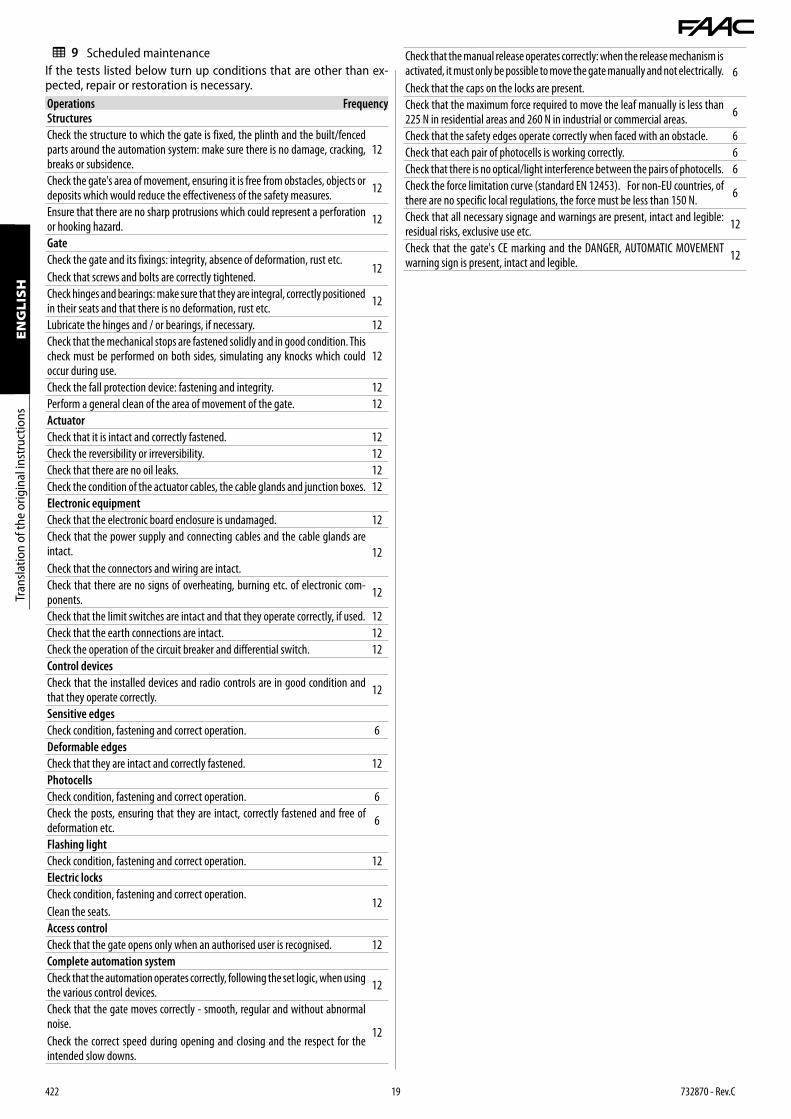
9.1 ROUTINE MAINTENANCEThe Scheduled Maintenance table ( 19 ) lists the operations that must be performed on a regular basis in order to keep the auto-mation system working reliably and safely; these are given purely as a guideline and should not be considered exhaustive. The installer/machine manufacturer is responsible for drawing up the maintenance plan for the automation, supplementing this list or modifying the maintenance intervals according to the machine characteristics.
422 19 732870 - Rev.C
Tran
slatio
n of
the
orig
inal
inst
ruct
ions
ENGLISH
Tran
slatio
n of
the
orig
inal
inst
ruct
ions
ENGLISH
9 Scheduled maintenanceIf the tests listed below turn up conditions that are other than ex-pected, repair or restoration is necessary.Operations FrequencyStructuresCheck the structure to which the gate is fixed, the plinth and the built/fenced parts around the automation system: make sure there is no damage, cracking, breaks or subsidence.
12
Check the gate's area of movement, ensuring it is free from obstacles, objects or deposits which would reduce the effectiveness of the safety measures. 12
Ensure that there are no sharp protrusions which could represent a perforation or hooking hazard. 12
GateCheck the gate and its fixings: integrity, absence of deformation, rust etc.Check that screws and bolts are correctly tightened.
12
Check hinges and bearings: make sure that they are integral, correctly positioned in their seats and that there is no deformation, rust etc. 12
Lubricate the hinges and / or bearings, if necessary. 12Check that the mechanical stops are fastened solidly and in good condition. This check must be performed on both sides, simulating any knocks which could occur during use.
12
Check the fall protection device: fastening and integrity. 12Perform a general clean of the area of movement of the gate. 12ActuatorCheck that it is intact and correctly fastened. 12Check the reversibility or irreversibility. 12Check that there are no oil leaks. 12Check the condition of the actuator cables, the cable glands and junction boxes. 12Electronic equipmentCheck that the electronic board enclosure is undamaged. 12Check that the power supply and connecting cables and the cable glands are intact.Check that the connectors and wiring are intact.
12
Check that there are no signs of overheating, burning etc. of electronic com-ponents. 12
Check that the limit switches are intact and that they operate correctly, if used. 12Check that the earth connections are intact. 12Check the operation of the circuit breaker and differential switch. 12Control devicesCheck that the installed devices and radio controls are in good condition and that they operate correctly. 12
Sensitive edgesCheck condition, fastening and correct operation. 6Deformable edgesCheck that they are intact and correctly fastened. 12Photocells Check condition, fastening and correct operation. 6Check the posts, ensuring that they are intact, correctly fastened and free of deformation etc. 6
Flashing lightCheck condition, fastening and correct operation. 12Electric locksCheck condition, fastening and correct operation.Clean the seats.
12
Access controlCheck that the gate opens only when an authorised user is recognised. 12Complete automation systemCheck that the automation operates correctly, following the set logic, when using the various control devices. 12
Check that the gate moves correctly - smooth, regular and without abnormal noise.Check the correct speed during opening and closing and the respect for the intended slow downs.
12
Check that the manual release operates correctly: when the release mechanism is activated, it must only be possible to move the gate manually and not electrically.Check that the caps on the locks are present.
6
Check that the maximum force required to move the leaf manually is less than 225 N in residential areas and 260 N in industrial or commercial areas. 6
Check that the safety edges operate correctly when faced with an obstacle. 6Check that each pair of photocells is working correctly. 6Check that there is no optical/light interference between the pairs of photocells. 6Check the force limitation curve (standard EN 12453). For non-EU countries, of there are no specific local regulations, the force must be less than 150 N. 6
Check that all necessary signage and warnings are present, intact and legible: residual risks, exclusive use etc. 12
Check that the gate's CE marking and the DANGER, AUTOMATIC MOVEMENT warning sign is present, intact and legible. 12

422 20 732870 - Rev.C
90°
90°
29
30
10.1 SAFETY RECOMMENDATIONSThe 422 is intended for installation on gates in areas that are acces-sible by people, the main purpose of which is to provide access for goods, vehicles and people.The user must be in good physical and mental health and be aware of and responsible for the dangers which use of the product can lead to.
! - Do not remain in or walk/drive through the area of operation of the automa-tion while it is moving.- Do not use the automation when the area of operation is not free of persons, animals or objects.- Do not allow children to approach or play in the area of operation of the automation.- Do not try to prevent the movement of the automation.- Do not climb on, hold onto or let yourself be pulled by the leaf.- Do not allow the devices to be used by anyone who is not specifically authorised and trained to do so.- Do not allow the devices to be controlled by children or persons with mental and physical deficiencies unless they are supervised by an adult who is responsible for their safety.- Do not use the automation with the fixed and/or mobile guards removed or altered.- Do not use the automation in the presence of faults which could compromise safety.- Do not expose the automation system to corrosive chemical or atmospheric agents; do not expose the actuator to corrosive chemical or atmospheric agents.- Do not expose the automation to flammable gases or fumes.- Do not perform any work on the components of the automation.
It is the responsibility of the machine installer/manufacturer to draft the user instructions of the automation in accordance with the Ma-chinery Directive, including all the required information and instruc-tions based on the characteristics of the automation.The guidelines below, which are purely indicative and in no way exhaustive, help the installer draft the user instructions.
! The installer must provide the owner/operator of the automation with the EC Declaration, the system Logbook with the maintenance schedule and the user instructions of the automation.The installer must inform the owner/operator of any residual risks and the intended use and ways in which the machine should not be used.The owner is responsible for operating the automation and must:- comply with all User instructions provided by the installer/maintenance technician and the Safety recommendations- keep the user instructions- have the maintenance schedule implemented - keep the system Logbook, which must be completed by the maintenance technician at the end of all servicing
10.3 MANUAL OPERATIONIn order to operate the leaf manually, the actuator has to be released using the key provided.
! Disconnect the power supply from the automation before releasing the actuator.During manual operation, gently guide the leaf the whole way. Do not push it and let it slide freely.Do not leave the actuator in the released mode: restore automatic operation after moving it manually.
RELEASING THE ACTUATOR (29 )1. Open the lock cover.2. Insert the key and turn it clockwise by 90°.3. Open the release device cover.4. Turn the knob fully anticlockwise without forcing it (about two
complete turns). Move the barrier manually.
RESTORING OPERATION (30 )1. Turn the knob fully clockwise.2. Close the release device cover.3. Turn the key anticlockwise by 90°, then remove it.4. Close the lock cover.
10. INSTRUCTIONS FOR USE
In emergencies or if there is a fault, turn off the power supply to the automation. If the leaf can be moved safely by hand, use the MANUAL OPERATION mode; otherwise place the automation out of service until it has been reset/repaired.
Environmental phenomena, even occasional, such as ice, snow and strong wind may hinder correct operation of the automation and affect component integrity and may become a potential source of danger.
10.2 EMERGENCY USE
Releasing the actuator
Restoring operation
In the case of a breakdown, the automation must be reset/repaired exclusively by the installer/maintenance technician.
422 21 732870 - Rev.C
Tran
slatio
n of
the
orig
inal
inst
ruct
ions
ENGLISH
Tran
slatio
n of
the
orig
inal
inst
ruct
ions
ENGLISH
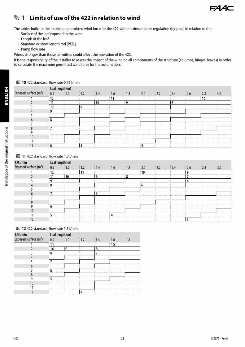
1 Limits of use of the 422 in relation to wind
The tables indicate the maximum permitted wind force for the 422 with maximum force regulation (by-pass) in relation to the: - Surface of the leaf exposed to the wind - Length of the leaf - Standard or short length rod (PED.) - Pump flow rate
Winds stronger than those permitted could affect the operation of the 422.It is the responsibility of the installer to assess the impact of the wind on all components of the structure (columns, hinges, leaves) in order to calculate the maximum permitted wind force for the automation.
10 422 standard, flow rate 0.75 l/min
Exposed surface (m²)Leaf length (m)0.9 1.0 1.2 1.4 1.6 1.8 2.0 2.2 2.4 2.6 2.8 3.0
1 12 11 102 11 10 9 83 10 94 956 878 79
101112 6 5 4
11 422 standard, flow rate 1.0 l/min1.0 l/minExposed surface (m²)
Leaf length (m)0.9 1.0 1.2 1.4 1.6 1.8 2.0 2.2 2.4 2.6 2.8 3.0
1 12 11 10 92 11 10 9 8 73 9 64 8 656 7 6789 6
1011 5 412 3
12 422 standard, flow rate 1.5 l/min1.5 l/minExposed surface (m²)
Leaf length (m)0.9 1.0 1.2 1.4 1.6 1.8
1 11 102 10 9 83 8 745 767 689 5
101112 4

422 22 732870 - Rev.C
13 422 PED. flow rate 1.5 l/minPED.Exposed surface (m²)
Leaf length (m)0.8 0.9 1.0 1.2 1.4
1.0 11 10 91.5 10 9 82.0 92.5 83.03.5 74.0 6 5
Beaufort number and description(Beaufort scale)
Wind speed (km/h)
0 Calm ≤ 11 Light air > 1…62 Light breeze > 6…113 Gentle breeze > 11…194 Moderate breeze > 19…295 Fresh breeze > 29…396 Strong breeze > 39…507 High wind > 50…628 Gale > 62…759 Severe gale > 75…8710 Storm > 87…10211 Violent storm > 102…11712 Hurricane force > 117

31
422 23 732870 - Rev.C
A
B
D
Z
S
Y
Tran
slatio
n of
the
orig
inal
inst
ruct
ions
ENGLISH
Tran
slatio
n of
the
orig
inal
inst
ruct
ions
ENGLISH
2 Outward opening applications
For applications in which the gate opens outwards, see 14 , 15 and 31 to establish the correct position for the rear bracket.
Li Keep to the measurements indicated. If necessary, modify the length and shape of the rear bracket arm.
Install the actuator as indicated in the specific section.During start-up, disconnect power and swap the phase wires of the motor to modify the direction of travel for this application.
ADJUSTING THE FORCE (BY-PASS)To regulate the opening and closing force, adjust the by-pass screw as follows:
- CLOSE screw = regulates the force of the leaf during opening - OPEN screw = regulates the force of the leaf during closing - tighten to increase the force + - loosen to decrease the force –
Regulate the force as indicated in the specific section.
14 Distances 422 StandardS = 0 B
90 100 110 120 130 140 150 160
A
70 125° ➁ 115° ➀ 110° ➀ 100° ➀ 95° ➀ 90° ➀80 120° ➁ 110° 105° 95° 90°90 115° ➁ 115° 105° 100° 90° 90°100 125° ➁ 105° 100° 95°110 110° ➁ 100° 95° 90°120 90° ➁ 105°
S = 20 B70 80 90 100 110 120 130 140 150
A
90 90° ➀ 95° ➀ 100° ➀ 105° ➁ 110° ➀ 105° ➀ 100° ➀ 90° ➀ 90° ➀100 90° 95° 100° 105° 110° 100° 95° 90°110 90° 95° 100° 105° 100° 95° 90°120 90° 95° 100° 105° 95° 90°130 90° 95° 100° 95° 90°140 90° 95° 100° 90°
S = 40 B80 90 100 110 120 130
A
110 90° ➀ 95° ➀ 100° ➀ 95° ➀ 90° ➀120 90° 90° 95° 95° 90°130 90° 90° 95° 90°140 90° 90° 90°150 90° 90°160 90°
15 Distances 422 PED.S = 0 B
60 70 80 90
A
70 100° ➀➁ 105° ➀➁ 95° ➀ 90° ➀80 100° ➁ 100° 90°90 100° ➁ 90°100 90°
S = 10 B60 70 80
A
80 90° ➀ 100° ➀ 90° ➀90 90° ➁ 90°100 90°
S = 20 B60 70
A90 90° ➀ 90° ➀100 90°
➀ indicates that a closing electric lock has to be installed.➁ indicates that the speed of the leaf could be uneven
during the final stage of movement.

422 24 732870 - Rev.C

422 25 732870 - Rev.C

FAAC S.p.A. Soc. UnipersonaleVia Calari, 10 - 40069 Zola Predosa BOLOGNA - ITALYTel. +39 051 61724 - Fax +39 051 09 57 820www.faac.it - www.faacgroup.com
422 26 732870 - Rev.C