Embed Size (px)
Citation preview
HERZ ArmaturenRichard-Strauss-Straße 22 • A-1230 Wiene-mail: [email protected] • www.herz-armaturen.com
1
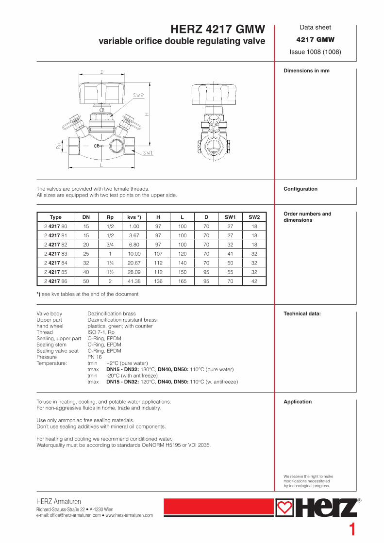
HERZ 4217 GMWvariable orifi ce double regulating valve
Data sheet
4217 GMW
Issue 1008 (1008)
Dimensions in mm
The valves are provided with two female threads.All sizes are equipped with two test points on the upper side.
Configuration
Type DN Rp kvs *) H L D SW1 SW2
2 4217 80 15 1/2 1.00 97 100 70 27 18
2 4217 81 15 1/2 3.67 97 100 70 27 18
2 4217 82 20 3/4 6.80 97 100 70 32 18
2 4217 83 25 1 10.00 107 120 70 41 32
2 4217 84 32 1¼ 20.67 112 140 70 50 32
2 4217 85 40 1½ 28.09 112 150 95 55 32
2 4217 86 50 2 41.38 136 165 95 70 42
*) see kvs tables at the end of the document
Order numbers anddimensions
Valve body Dezincification brass Upper part Dezincification resistant brasshand wheel plastics, green; with counterThread ISO 7-1, RpSealing, upper part O-Ring, EPDMSealing stem O-Ring, EPDMSealing valve seat O-Ring, EPDMPressure PN 16Temperature: tmin +2°C (pure water) tmax DN15 - DN32: 130°C, DN40, DN50: 110°C (pure water) tmin -20°C (with antifreeze) tmax DN15 - DN32: 120°C, DN40, DN50: 110°C (w. antifreeze)
Technical data:
To use in heating, cooling, and potable water applications.For non-aggressive fluids in home, trade and industry.
Use only ammoniac free sealing materials.Don’t use sealing additives with mineral oil components.
For heating and cooling we recommend conditioned water. Waterquality must be according to standards OeNORM H5195 or VDI 2035.
Application
We reserve the right to make modifications necessitated by technological progress.

2
HERZ - “PipeFix” Pipe and Fitting system:
273 Drain plug for hex-keys 276 Drain valve with rotatable hose connector.
1 284 01/02 Testpoint for heating2 284 01/02 Testpoint for potable water
1 284 11/12 Testpoint, long model for insulation up to 40 mm
284 Testpoint with integrated drain valve
Accessories
To get correct measuring results, we recommend a straight piece of pipe before and after the valve.Upstream 10x pipe diameter, downstream 5x pipe diameter.
Messurement
4117 MW STRÖMAX Balancing valve for potable water, Y-form, DN 15 - DN 50 4217 GM STRÖMAX Balancing valve for heating and cooling, straight-form, DN 15 - DN 80 4215 AG STRÖMAX Shut-off valve for heating and cooling, straight-form, DN 15 - DN 80 4218 GMF STRÖMAX Balancing valve for heating and cooling, straight-form, grey cast valve
body with flange connection and brass upperparts, DN 25 - DN 80 4218 GF STRÖMAX Balancing valve for heating and cooling, straight-form, body and upper
part from grey cast, valve body with flange connection, DN 50 - DN 300 4219 Butterfly valves, cast iron, DN 50 - DN 300 4010 Circulation Temperature controllers for district heating plants 4011 Circulation Temperature controllers with legionella protection 4216 STROMAX-MS, Regulation Valve for manual adjustment 4007 Differntial pressure controller 4037 HERZ Three-way mixing and diverting valve 4000 HERZ metering sation with two testpoints, DN 15 - DN 50, kvs 0,55 ....48 m3/h 4017 HERZ FODRV, Fixed orificed double regulating valves, DN 15 - DN 50 4217 GMW STRÖMAX Balancing valve with solder connection special edition on request
Other products
The non-rising valve spindle arranged perpendicular to the valve axis guarantees optimum accessibility and optimum valve operation in any installation position.
Installation Position
The current position of the flow restriction cone is shown on a clearly visible digital display on the front side of the hand wheel. The desired presetting step can be easily adjusted and secured by means of the covered presetting spindle located inside the valve. The preset circuit control valve can be shut off at any time and/or can be set to any desired position below the fixed presetting. The presetting spindle is covered by the hand wheel fastening screw and thus protected against unauthorized operation.
Presetting

3
Preset SealingThe presetting seal (1 6517 04) is attached above the hand wheel fastening screw to prevent unauthorized operation. If the seal is removed it breaks and cannot be mounted again. Therefore, it can be clearly seen whether tampering with the valve has occurred.
Presetting MarkerThe pre-setting marker (1 6517 05) is fastened as a tag above the valve or pipe. The setting of the respective valve is marked by cutting or breaking off the teeth at the figures for full and partial turns. This permits checking and/or restoration of the original pre-setting made on the occasion of the system set-up after servicing without having to rely on documentation.
The double-O-ring seals of both the main spindle and the presetting spindle ensure complete and lasting tightness and ease of valve operation. The seals have been approved for a max. operating temperature of 130 °C.
The temperature-resistant and permanently elastic soft seal is corrosion-resistant, permits operation with a low shutting force, and has been approved for a maximum operating temperature of 130°C.
Spindle Seal
Seat Seal
Setting and Fixing The STRÖMAX-GMW circuit control valves are supplied in open position, preset to permit the maximum possible valve lift. The hand wheel mechanism is adjusted in such a way that the digital reading will be 0.0 when the valve is closed.
Presetting Procedure1. Set to the desired step according to calculation (digital display on the hand wheel).2. Remove the hand wheel locking screw, do not remove the hand wheel from the valve.3. Screw the presetting spindle, which is now accessible, in up to the stop.4. Screw in the hand wheel locking screw again.5. Seal with presetting seal.6. Mark the step set at the presetting marker and attach the marker to the valve.
Points 5 and 6 are not necessary for function, but are recommended. When using a differential manometer setting can be performed only on the basis of the HERZ-setting diagrams. A flowrate for the STRÖMAX-GMW valve can only be set without specifying a pre-setting step if a measuring instrument is used. Follow the operating instructions when using a measuring computer.
Presetting
Factory Setting The factory setting of the digital display is 0.0 when the valve is closed. If the complete hand wheel (rotating grip, figure wheels, base plate) is removed from the valve or if a defective part has to be replaced, proceed as follows to ensure correct digital display reading:1. Return the complete hand wheel into position and slide it onto the valve until the hexagon at the
valve body and the spindle gear interlock.2. Shut the valve by turning clockwise.3. If the digital display reads 0.0 in the shut position, the hand wheel has been positioned correct
and can be secured by means of the locking screw. In case of a different reading remove the complete hand wheel.
4. Twist the base plate and rotating grip until the digital display reads 0.0 and then return the complete hand wheel into position without twisting the spindle.
5. Tighten hand wheel locking screw.
Then, the valve can be set to the desired position.
Digital Display
HERZ ArmaturenRichard-Strauss-Straße 22 • A-1230 Wiene-mail: [email protected] • www.herz-armaturen.com
4
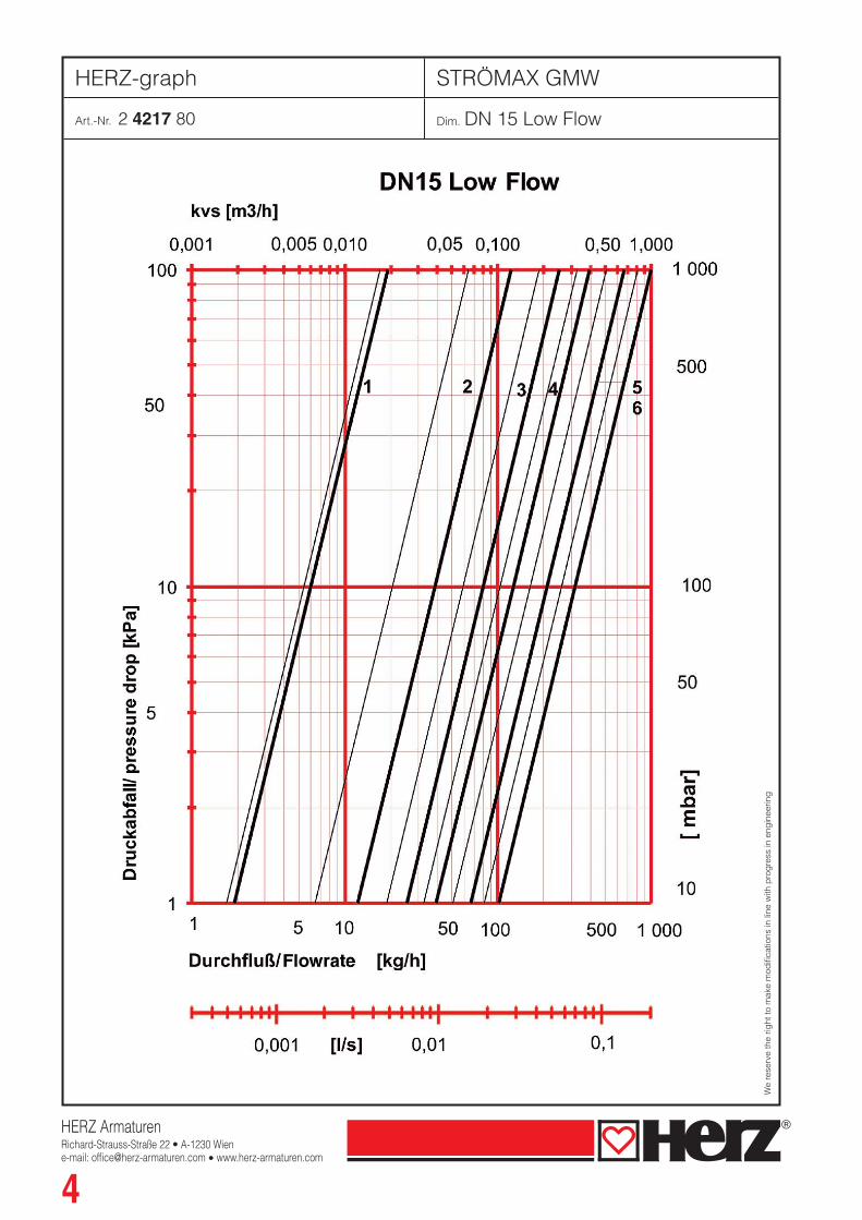
HERZ-graph STRÖMAX GMW
Art.-Nr. 2 4217 80 Dim. DN 15 Low Flow
We
rese
rve
the
right
to m
ake
mod
ifi ca
tions
in li
ne w
ith p
rog
ress
in e
ngin
eerin
g
HERZ ArmaturenRichard-Strauss-Straße 22 • A-1230 Wiene-mail: [email protected] • www.herz-armaturen.com
5
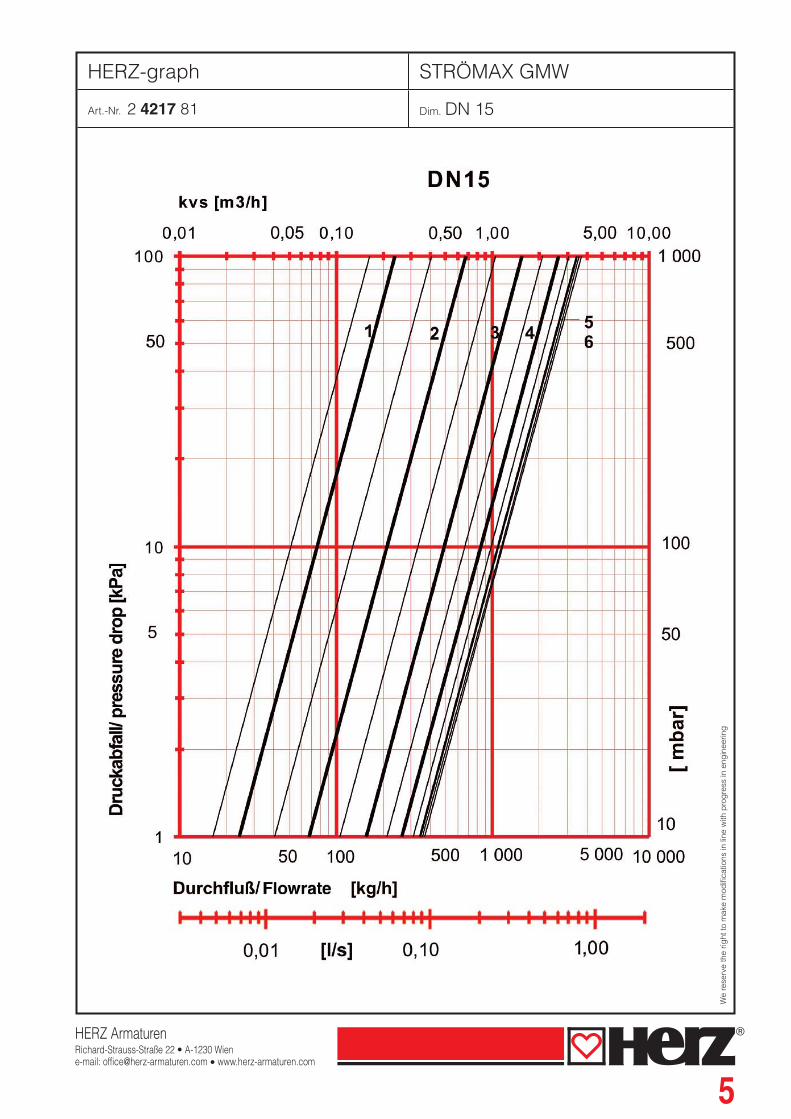
HERZ-graph STRÖMAX GMW
Art.-Nr. 2 4217 81 Dim. DN 15
We
rese
rve
the
right
to m
ake
mod
ifi ca
tions
in li
ne w
ith p
rog
ress
in e
ngin
eerin
g

HERZ ArmaturenRichard-Strauss-Straße 22 • A-1230 Wiene-mail: [email protected] • www.herz-armaturen.com
6
HERZ-graph STRÖMAX GMW
Art.-Nr. 2 4217 82 Dim. DN 20
We
rese
rve
the
right
to m
ake
mod
ifi ca
tions
in li
ne w
ith p
rog
ress
in e
ngin
eerin
g

HERZ ArmaturenRichard-Strauss-Straße 22 • A-1230 Wiene-mail: [email protected] • www.herz-armaturen.com
7
HERZ-graph STRÖMAX GMW
Art.-Nr. 2 4217 83 Dim. DN 25
We
rese
rve
the
right
to m
ake
mod
ifi ca
tions
in li
ne w
ith p
rog
ress
in e
ngin
eerin
g

HERZ ArmaturenRichard-Strauss-Straße 22 • A-1230 Wiene-mail: [email protected] • www.herz-armaturen.com
8
HERZ-graph STRÖMAX GMW
Art.-Nr. 2 4217 84 Dim. DN 32
We
rese
rve
the
right
to m
ake
mod
ifi ca
tions
in li
ne w
ith p
rog
ress
in e
ngin
eerin
g

HERZ ArmaturenRichard-Strauss-Straße 22 • A-1230 Wiene-mail: [email protected] • www.herz-armaturen.com
9
HERZ-graph STRÖMAX GMW
Art.-Nr. 2 4217 85 Dim. DN 40
We
rese
rve
the
right
to m
ake
mod
ifi ca
tions
in li
ne w
ith p
rog
ress
in e
ngin
eerin
g

HERZ ArmaturenRichard-Strauss-Straße 22 • A-1230 Wiene-mail: [email protected] • www.herz-armaturen.com
10
HERZ-graph STRÖMAX GMW
Art.-Nr. 2 4217 86 Dim. DN 50
We
rese
rve
the
right
to m
ake
mod
ifi ca
tions
in li
ne w
ith p
rog
ress
in e
ngin
eerin
g

11
Signal kv values for each preset handwheel position
Test points
kv-value [m3/h](Testing)
presetting DN 15 DN 20 DN 25 DN 32 DN 40 DN 50
0.5 0.16 0.44 0.48 0.72 0.25 1.41
0.6 0.17 0.47 0.49 0.74 0.35 1.42
0.7 0.18 0.50 0.50 0.79 0.44 1.52
0.8 0.20 0.53 0.53 0.85 0.52 1.66
0.9 0.22 0.57 0.56 0.93 0.60 1.86
1 0.24 0.62 0.59 1.02 0.68 2.08
1.1 0.27 0.67 0.64 1.12 0.76 2.33
1.2 0.29 0.72 0.68 1.23 0.84 2.59
1.3 0.33 0.78 0.74 1.35 0.93 2.87
1.4 0.36 0.84 0.79 1.47 1.01 3.15
1.5 0.40 0.91 0.86 1.60 1.10 3.43
1.6 0.45 0.99 0.92 1.73 1.19 3.72
1.7 0.50 1.07 0.99 1.86 1.29 4.01
1.8 0.55 1.15 1.06 2.00 1.39 4.29
1.9 0.61 1.24 1.13 2.13 1.50 4.59
2 0.67 1.34 1.21 2.27 1.62 4.88
2.1 0.74 1.44 1.29 2.41 1.74 5.19
2.2 0.81 1.55 1.37 2.55 1.86 5.50
2.3 0.89 1.67 1.46 2.69 1.99 5.82
2.4 0.97 1.79 1.54 2.83 2.13 6.17
2.5 1.06 1.92 1.63 2.97 2.27 6.53
2.6 1.15 2.05 1.72 3.11 2.42 6.91
2.7 1.24 2.19 1.82 3.26 2.58 7.31
2.8 1.34 2.33 1.91 3.41 2.74 7.75
2.9 1.44 2.48 2.01 3.56 2.91 8.22
3 1.55 2.63 2.11 3.71 3.08 8.72
3.1 1.66 2.78 2.21 3.87 3.26 9.25
3.2 1.77 2.94 2.31 4.03 3.45 9.82
3.3 1.88 3.10 2.42 4.20 3.64 10.44
3.4 1.99 3.27 2.52 4.37 3.83 11.09
3.5 2.10 3.43 2.64 4.55 4.03 11.78
3.6 2.21 3.60 2.75 4.74 4.24 12.51
3.7 2.32 3.76 2.86 4.93 4.45 13.28
3.8 2.43 3.93 2.98 5.13 4.67 14.10
3.9 2.54 4.09 3.11 5.34 4.90 14.94
4 2.64 4.25 3.23 5.55 5.12 15.83
4.1 2.75 4.41 3.36 5.78 5.36 16.74
4.2 2.84 4.56 3.49 6.01 5.60 17.69
4.3 2.94 4.72 3.62 6.26 5.85 18.66
4.4 3.02 4.86 3.76 6.51 6.10 19.65
4.5 3.11 5.01 3.90 6.77 6.36 20.66
4.6 3.18 5.14 4.04 7.05 6.63 21.69
4.7 3.25 5.28 4.19 7.33 6.90 22.72
4.8 3.31 5.40 4.34 7.62 7.18 23.76
4.9 3.37 5.53 4.50 7.92 7.47 24.79
5 3.42 5.65 4.65 8.23 7.77 25.82
12
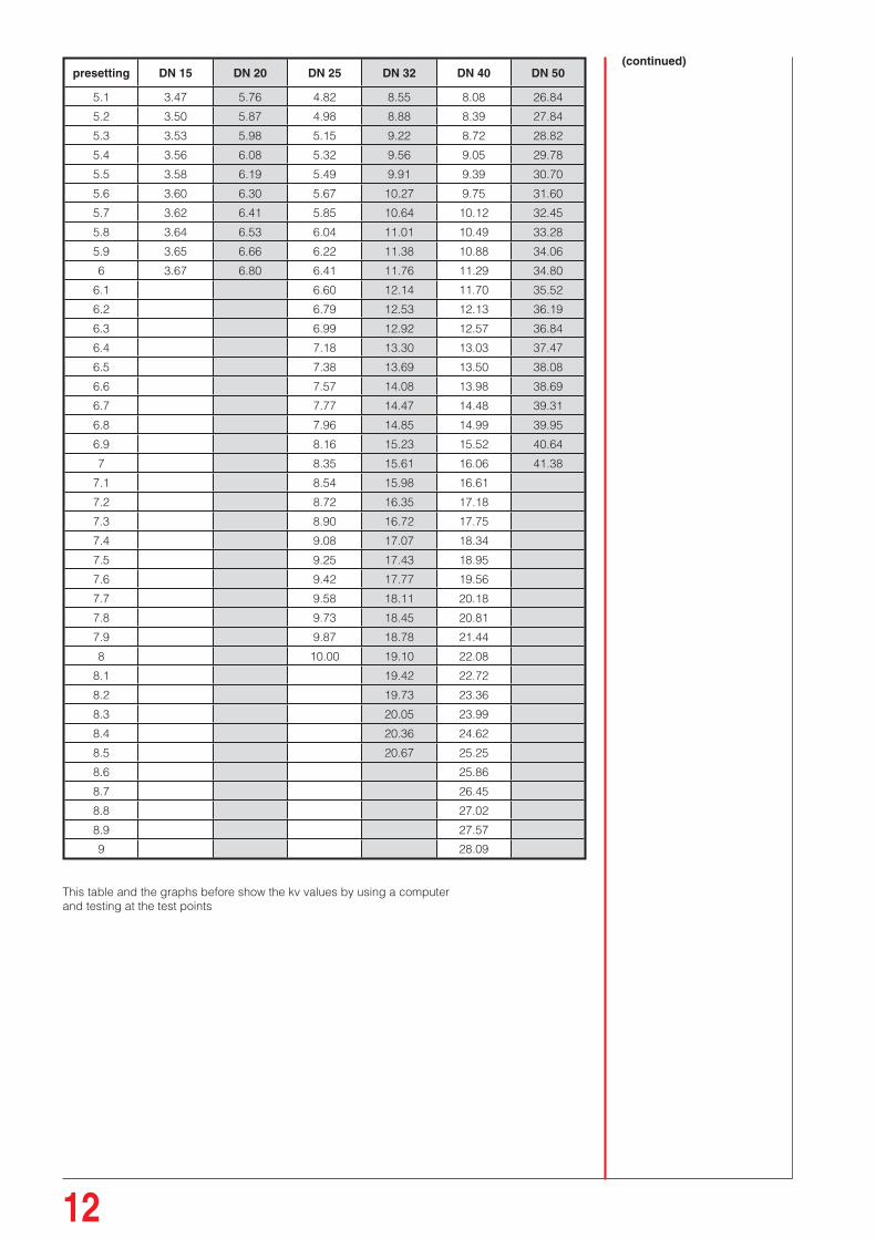
presetting DN 15 DN 20 DN 25 DN 32 DN 40 DN 50
5.1 3.47 5.76 4.82 8.55 8.08 26.84
5.2 3.50 5.87 4.98 8.88 8.39 27.84
5.3 3.53 5.98 5.15 9.22 8.72 28.82
5.4 3.56 6.08 5.32 9.56 9.05 29.78
5.5 3.58 6.19 5.49 9.91 9.39 30.70
5.6 3.60 6.30 5.67 10.27 9.75 31.60
5.7 3.62 6.41 5.85 10.64 10.12 32.45
5.8 3.64 6.53 6.04 11.01 10.49 33.28
5.9 3.65 6.66 6.22 11.38 10.88 34.06
6 3.67 6.80 6.41 11.76 11.29 34.80
6.1 6.60 12.14 11.70 35.52
6.2 6.79 12.53 12.13 36.19
6.3 6.99 12.92 12.57 36.84
6.4 7.18 13.30 13.03 37.47
6.5 7.38 13.69 13.50 38.08
6.6 7.57 14.08 13.98 38.69
6.7 7.77 14.47 14.48 39.31
6.8 7.96 14.85 14.99 39.95
6.9 8.16 15.23 15.52 40.64
7 8.35 15.61 16.06 41.38
7.1 8.54 15.98 16.61
7.2 8.72 16.35 17.18
7.3 8.90 16.72 17.75
7.4 9.08 17.07 18.34
7.5 9.25 17.43 18.95
7.6 9.42 17.77 19.56
7.7 9.58 18.11 20.18
7.8 9.73 18.45 20.81
7.9 9.87 18.78 21.44
8 10.00 19.10 22.08
8.1 19.42 22.72
8.2 19.73 23.36
8.3 20.05 23.99
8.4 20.36 24.62
8.5 20.67 25.25
8.6 25.86
8.7 26.45
8.8 27.02
8.9 27.57
9 28.09
This table and the graphs before show the kv values by using a computer and testing at the test points
(continued)
13
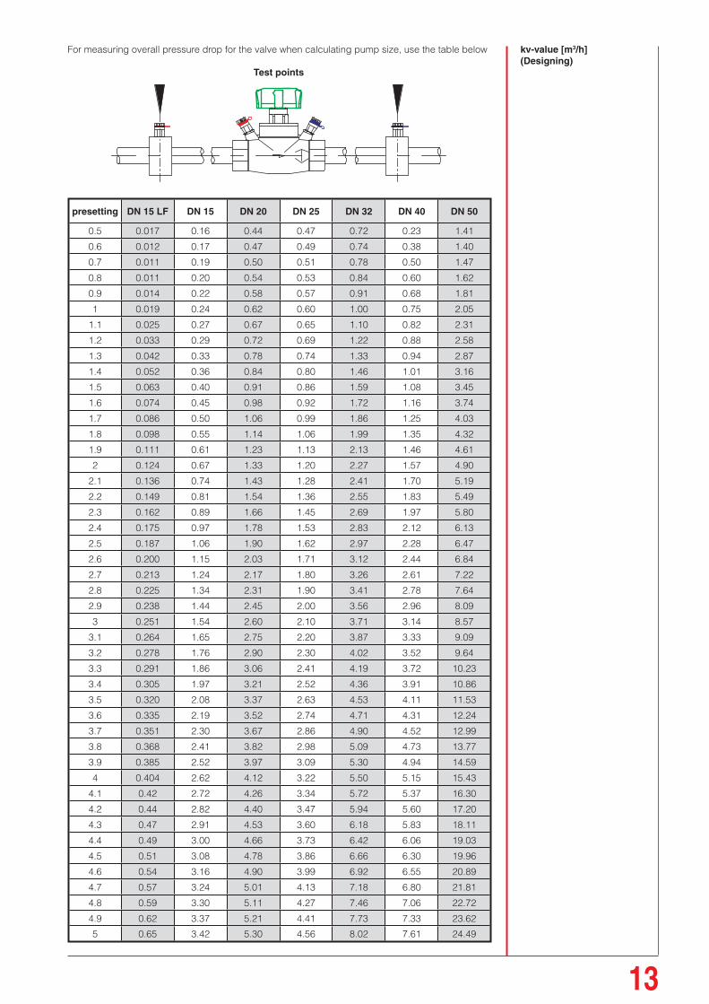
For measuring overall pressure drop for the valve when calculating pump size, use the table below
Test points
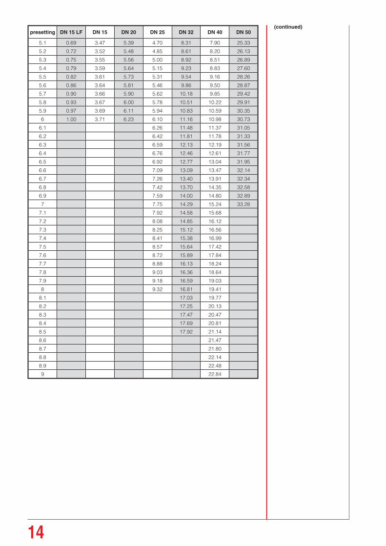
kv-value [m3/h](Designing)
presetting DN 15 LF DN 15 DN 20 DN 25 DN 32 DN 40 DN 50
0.5 0.017 0.16 0.44 0.47 0.72 0.23 1.41
0.6 0.012 0.17 0.47 0.49 0.74 0.38 1.40
0.7 0.011 0.19 0.50 0.51 0.78 0.50 1.47
0.8 0.011 0.20 0.54 0.53 0.84 0.60 1.62
0.9 0.014 0.22 0.58 0.57 0.91 0.68 1.81
1 0.019 0.24 0.62 0.60 1.00 0.75 2.05
1.1 0.025 0.27 0.67 0.65 1.10 0.82 2.31
1.2 0.033 0.29 0.72 0.69 1.22 0.88 2.58
1.3 0.042 0.33 0.78 0.74 1.33 0.94 2.87
1.4 0.052 0.36 0.84 0.80 1.46 1.01 3.16
1.5 0.063 0.40 0.91 0.86 1.59 1.08 3.45
1.6 0.074 0.45 0.98 0.92 1.72 1.16 3.74
1.7 0.086 0.50 1.06 0.99 1.86 1.25 4.03
1.8 0.098 0.55 1.14 1.06 1.99 1.35 4.32
1.9 0.111 0.61 1.23 1.13 2.13 1.46 4.61
2 0.124 0.67 1.33 1.20 2.27 1.57 4.90
2.1 0.136 0.74 1.43 1.28 2.41 1.70 5.19
2.2 0.149 0.81 1.54 1.36 2.55 1.83 5.49
2.3 0.162 0.89 1.66 1.45 2.69 1.97 5.80
2.4 0.175 0.97 1.78 1.53 2.83 2.12 6.13
2.5 0.187 1.06 1.90 1.62 2.97 2.28 6.47
2.6 0.200 1.15 2.03 1.71 3.12 2.44 6.84
2.7 0.213 1.24 2.17 1.80 3.26 2.61 7.22
2.8 0.225 1.34 2.31 1.90 3.41 2.78 7.64
2.9 0.238 1.44 2.45 2.00 3.56 2.96 8.09
3 0.251 1.54 2.60 2.10 3.71 3.14 8.57
3.1 0.264 1.65 2.75 2.20 3.87 3.33 9.09
3.2 0.278 1.76 2.90 2.30 4.02 3.52 9.64
3.3 0.291 1.86 3.06 2.41 4.19 3.72 10.23
3.4 0.305 1.97 3.21 2.52 4.36 3.91 10.86
3.5 0.320 2.08 3.37 2.63 4.53 4.11 11.53
3.6 0.335 2.19 3.52 2.74 4.71 4.31 12.24
3.7 0.351 2.30 3.67 2.86 4.90 4.52 12.99
3.8 0.368 2.41 3.82 2.98 5.09 4.73 13.77
3.9 0.385 2.52 3.97 3.09 5.30 4.94 14.59
4 0.404 2.62 4.12 3.22 5.50 5.15 15.43
4.1 0.42 2.72 4.26 3.34 5.72 5.37 16.30
4.2 0.44 2.82 4.40 3.47 5.94 5.60 17.20
4.3 0.47 2.91 4.53 3.60 6.18 5.83 18.11
4.4 0.49 3.00 4.66 3.73 6.42 6.06 19.03
4.5 0.51 3.08 4.78 3.86 6.66 6.30 19.96
4.6 0.54 3.16 4.90 3.99 6.92 6.55 20.89
4.7 0.57 3.24 5.01 4.13 7.18 6.80 21.81
4.8 0.59 3.30 5.11 4.27 7.46 7.06 22.72
4.9 0.62 3.37 5.21 4.41 7.73 7.33 23.62
5 0.65 3.42 5.30 4.56 8.02 7.61 24.49
14
presetting DN 15 LF DN 15 DN 20 DN 25 DN 32 DN 40 DN 50
5.1 0.69 3.47 5.39 4.70 8.31 7.90 25.33
5.2 0.72 3.52 5.48 4.85 8.61 8.20 26.13
5.3 0.75 3.55 5.56 5.00 8.92 8.51 26.89
5.4 0.79 3.59 5.64 5.15 9.23 8.83 27.60
5.5 0.82 3.61 5.73 5.31 9.54 9.16 28.26
5.6 0.86 3.64 5.81 5.46 9.86 9.50 28.87
5.7 0.90 3.66 5.90 5.62 10.18 9.85 29.42
5.8 0.93 3.67 6.00 5.78 10.51 10.22 29.91
5.9 0.97 3.69 6.11 5.94 10.83 10.59 30.35
6 1.00 3.71 6.23 6.10 11.16 10.98 30.73
6.1 6.26 11.48 11.37 31.05
6.2 6.42 11.81 11.78 31.33
6.3 6.59 12.13 12.19 31.56
6.4 6.76 12.46 12.61 31.77
6.5 6.92 12.77 13.04 31.95
6.6 7.09 13.09 13.47 32.14
6.7 7.26 13.40 13.91 32.34
6.8 7.42 13.70 14.35 32.58
6.9 7.59 14.00 14.80 32.89
7 7.75 14.29 15.24 33.28
7.1 7.92 14.58 15.68
7.2 8.08 14.85 16.12
7.3 8.25 15.12 16.56
7.4 8.41 15.38 16.99
7.5 8.57 15.64 17.42
7.6 8.72 15.89 17.84
7.7 8.88 16.13 18.24
7.8 9.03 16.36 18.64
7.9 9.18 16.59 19.03
8 9.32 16.81 19.41
8.1 17.03 19.77
8.2 17.25 20.13
8.3 17.47 20.47
8.4 17.69 20.81
8.5 17.92 21.14
8.6 21.47
8.7 21.80
8.8 22.14
8.9 22.48
9 22.84
(continued)

15
On plants with glycol-freeze protection, you must use correction factors in order to get the correct results. This fluid has a different density to pure water and is also temperature dependant.
Factors by using the HERZ-Flowplus computer
Temperature Ethylenglycol Ethylenglycol Ethylenglycol°C Conc. 34% Conc. 40% Conc. 44%
(Factor) (Factor) (Factor)-20 1.980 2.1330 2.235
-15 1.833 1.9908 2.096
-10 1.737 1.8738 1.965
-5 1.649 1.7702 1.851
0 1.567 1.6744 1.746
5 1.482 1.5876 1.658
10 1.412 1.505 1.567
15 1.342 1.4254 1.481
20 1.281 1.3554 1.405
25 1.226 1.2956 1.342
30 1.163 1.2284 1.272
35 1.123 1.1848 1.226
40 1.079 1.1360 1.174
45 1.040 1.0928 1.128
50 1 1.0528 1.088
55 0.974 1.0214 1.053
60 0.947 0.9938 1.025
65 0.926 0.9714 1
70 0.912 0.9528 0.980
75 0.893 0.9332 0.960
80 0.884 0.9242 0.951
Example: Glycolconcentration 40%, Temperature 35°C ---> factor 1.848dp to set 12 kPa.
12/ 1.848 = 6.49 kpa shown on computerdisplay.
16
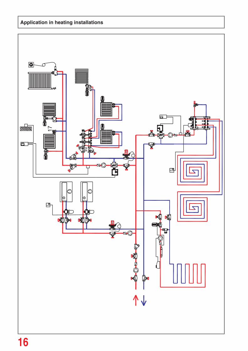
Application in heating installations
17
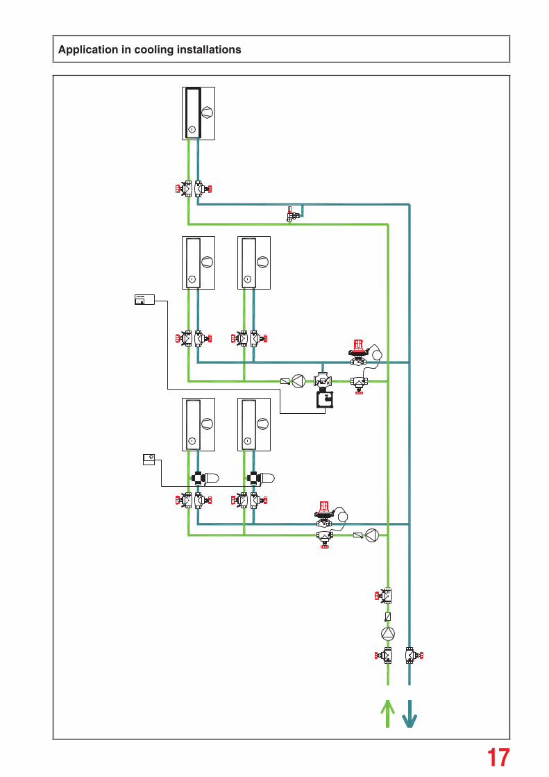
Application in cooling installations

18
Application in potable water installations
All diagrams have symbolic character and must not be complete.
All specifi cations and statements within this brochure are according to information available at the time of printing and meant for informational purpose only. HERZ Armaturen reserves the right to modify and change products as well as its technical specifi cations and/or it functioning according to technological progress and requirements. It is understood that all images of HERZ products are symbolic representations and therefore may visually differ from the actual product. Colours may differ due to printing technology used.In case of any further questions don’t hesitate to contact your closest HERZ Branch-offi ce.


Prin
ted
by B
ello
prin
t Ltd
.of
fice@
bello
prin
t.com


![[4217] – 447](https://img.pdfslide.us/doc/110x75/61ed6e37fbc61e6b780d5f86/4217-447.jpg)