Embed Size (px)
Citation preview
EV 420 Aligner SOP Page 1 of 8Revision 1-011210
EV 420 Aligner SOP
1. Scope
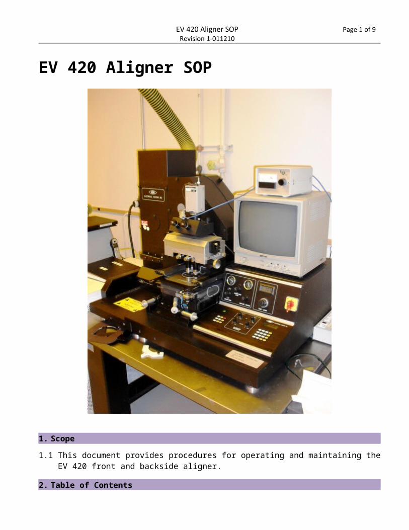
1.1 This document provides procedures for operating and maintaining the EV 420 front and backside aligner.
2. Table of Contents1. Scope...........................................................................................................................................................1
EV 420 Aligner SOP Page 2 of 8Revision 1-011210
2. Table of Contents........................................................................................................................................13. Reference Documents.................................................................................................................................2
3.1 Referenced within this Document.........................................................................................................23.2 External Documents..............................................................................................................................2
4. Equipment and/or Materials.......................................................................................................................25. Safety...........................................................................................................................................................26. Setup Procedures........................................................................................................................................3
6.1 Turn on UV Lamp...................................................................................................................................36.2 Replace Mask Holder.............................................................................................................................36.3 Turn on Aligner......................................................................................................................................4
7. Front Side Alignment Procedures................................................................................................................47.1 Load Mask.............................................................................................................................................47.2 Align Mask.............................................................................................................................................47.3 Load and Align Sample..........................................................................................................................57.4 Enter Exposure Time.............................................................................................................................57.5 Contact Mask and Sample.....................................................................................................................57.6 Expose and Remove Sample..................................................................................................................67.7 Remove Mask and Shutdown................................................................................................................6
8. Back Side Alignment....................................................................................................................................68.1 Align Mask and Sample.........................................................................................................................6
9. Process Notes..............................................................................................................................................79.1 Exposing Thick SU-8..............................................................................................................................79.2 Adjust Pressures....................................................................................................................................7
10. Revision History...........................................................................................................................................7
Figure 1, UV Lamp Power Supply..............................................................................................................................3Figure 2, Control Panel.............................................................................................................................................4Figure 3, Microscope Light Power Supply.................................................................................................................5
3. Reference Documents
3.1 Referenced within this Document
3.1.1 None
3.2 External Documents
3.2.1 None
4. Equipment and/or Materials
4.1 EV 420 Aligner
4.2 Mask
4.3 Wafer/Sample
5. Safety
5.1 Follow all Nanofab safety procedures.
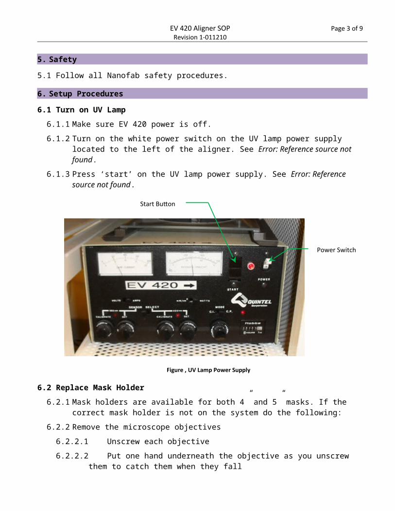
Power Switch
Start Button
Figure , UV Lamp Power Supply
EV 420 Aligner SOP Page 3 of 8Revision 1-011210
6. Setup Procedures
6.1 Turn on UV Lamp
6.1.1 Make sure EV 420 power is off.
6.1.2 Turn on the white power switch on the UV lamp power supply located to the left of the aligner. See Error: Reference source not found.
6.1.3 Press ‘start’ on the UV lamp power supply. See Error: Reference source not found.
6.2 Replace Mask Holder
6.2.1 Mask holders are available for both 4” and 5” masks. If the correct mask holder is not on the system do the following:
6.2.2 Remove the microscope objectives
6.2.2.1 Unscrew each objective
6.2.2.2 Put one hand underneath the objective as you unscrew them to catch them when they fall
6.2.2.3 Place the objectives in a safe place where they won’t fall and get damaged.
6.2.3 Remove the mask holder
6.2.3.1 Unscrew thumbscrews on each side of the mask holder and slide the sliders away
6.2.3.2 Lift up gently and slide mask holder towards front of the aligner
6.2.3.3 Put mask holder in the top drawer of the white spinner bench.
6.2.4 Install the new mask holder
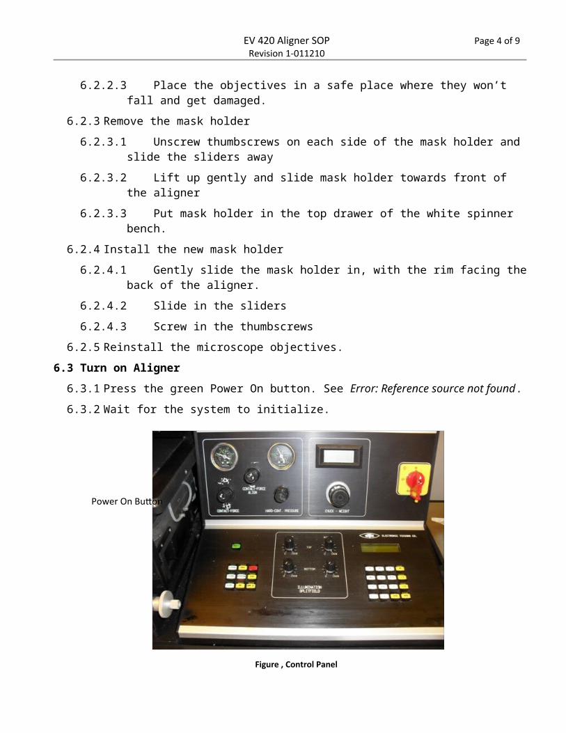
Figure , Control Panel
Power On Button
EV 420 Aligner SOP Page 4 of 8Revision 1-011210
6.2.4.1 Gently slide the mask holder in, with the rim facing the back of the aligner.
6.2.4.2 Slide in the sliders
6.2.4.3 Screw in the thumbscrews
6.2.5 Reinstall the microscope objectives.
6.3 Turn on Aligner
6.3.1 Press the green Power On button. See Error: Reference source not found.
6.3.2 Wait for the system to initialize.
7. Front Side Alignment Procedures
7.1 Load Mask
7.1.1 Move out the tray when prompted.
7.1.2 Load the mask frame with the three plastic pins facing up.
7.1.3 Place the mask face down between the three pins.
7.1.4 Move the tray in.
7.1.5 Wait for the mask to level.
7.2 Align Mask
7.2.1 Turn on the microscope light power supply. See Error: Reference source not found.
7.2.2 Adjust the voltage until it reads 7.0 V. See Error: Reference source not found.
7.2.3 View the mask through the optics.
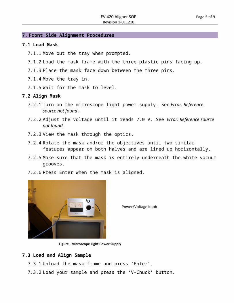
Power/Voltage Knob
Figure , Microscope Light Power Supply
EV 420 Aligner SOP Page 5 of 8Revision 1-011210
7.2.4 Rotate the mask and/or the objectives until two similar features appear on both halves and are lined up horizontally.
7.2.5 Make sure that the mask is entirely underneath the white vacuum grooves.
7.2.6 Press Enter when the mask is aligned.
7.3 Load and Align Sample
7.3.1 Unload the mask frame and press ‘Enter’.
7.3.2 Load your sample and press the ‘V-Chuck’ button.
7.3.3 Press ‘Enter” when it says ‘remove ruler’ on the LCD.
7.3.4 Move the tray in when prompted.
7.3.5 Wait for the system to level. The LCD will read ‘align wafer’ when it is done leveling.
7.3.6 Align the wafer to the mask using the micrometers to rotate the substrate or move it back and forth.
7.4 Enter Exposure Time
7.4.1 Press ‘Menu’.
7.4.2 Press the right arrow once (numeric keypad 6) to select ‘Proc’ on the display.
7.4.3 Press ‘Enter’.
7.4.4 Press ‘Enter’.
7.4.5 Press ‘Enter’.
7.4.6 Press ‘Enter’.
7.4.7 Press ‘Enter’.
7.4.8 Enter the desired exposure time.
7.4.9 Press ‘Enter’.
7.4.10 Press ‘Enter’.
EV 420 Aligner SOP Page 6 of 8Revision 1-011210
7.4.11 Press ‘Menu’.
7.5 Contact Mask and Sample
7.5.1 When the substrate and mask are aligned, press the ‘separation’ button.
7.5.2 Press the ‘H-Cont’ button and wait until it says ‘Adjust Chamber Vaccum’.
7.5.3 Make sure the hard-cont pressure gauge reads a max of 1 bar, then press ‘Enter’.
7.6 Expose and Remove Sample
7.6.1 Press the ‘EXP’ button when it is selected.
7.6.2 Wait for the prompt, then move tray out and remove sample.
7.6.3 Load another sample if desired (see 7.1).
7.7 Remove Mask and Shutdown
7.7.1 Press the red “RESET” key.
7.7.2 Press ‘Enter’ when the LCD reads ‘unload mask’.
7.7.3 Move tray in when prompted.
7.7.4 Move tray out when prompted.
7.7.5 Remove your mask.
8. Back Side Alignment
8.1 Align Mask and Sample
8.1.1 Move tray out when prompted.
8.1.2 Place the mask face down but DO NOT use the mask frame with the three pins.
8.1.3 Move tray in when prompted.
8.1.4 Wait for the mask to level (LCD will read ‘align mask’).
8.1.5 Turn up the backside (bottom) illumination on the control panel.
8.1.6 Press the TB button.
8.1.7 On the TV monitor turn brightness down all the way and turn contrast up all the way.
8.1.8 Turn off the top illumination and the room lights.
8.1.9 Press LR to toggle between moving the microscope objectives.
8.1.10 Press the up and down arrows to focus the left and right objectives.
8.1.11 Align the crosses on the mask to the crosses on the TV screen by rotating and moving the mask left and right with the micrometers.
8.1.12 Press ‘enter’ and the mask vacuum will turn on.
8.1.13 Load the wafer (see 7.1).
8.1.14 Do not touch the bottom focus or move the bottom lenses. Move only the sample when it tells you to align the sample.
EV 420 Aligner SOP Page 7 of 8Revision 1-011210
8.1.15 Align the crosses on the backside of the sample to the crosses on the TV screen.
8.1.16 Press the ‘Enter’ button when the sample is aligned.
8.1.17 Set the exposure time (see 7.4).
8.1.18 Expose and remove the sample (see 7.6).
8.1.19 Shut down the system (see 7.7).
9. Process Notes
9.1 Exposing Thick SU-8
9.1.1 Use a filter over top of mask
9.1.2 Break up exposure into small time increments (~30 sec. intervals) so SU-8 does not over heat and cure before development.
9.1.2.1 Menu>Proc>Expo>Exp>Preset>Edit>1
9.1.2.2 Enter total exposure time in seconds
9.1.2.3 Int- enter # of breaks
9.1.2.4 Enter break time (lamp off time)
9.1.2.5 Proximity off
9.1.2.6 Enter separation gap (typically 80 um)
9.1.2.7 Select>1>Menu
9.2 Adjust Pressures
9.2.1 Contact Force-Align: 1.1
9.2.1.1 This is what the left gage usually reads, except during WEC.
9.2.2 Chuck Weight: should be between 0.26-0.29 (bellows under WEC unit)
9.2.3 To calibrate WEC Chuck Weight:
9.2.3.1 Menu>Proc>Exp>WEC>Cal
9.2.3.2 Load substrate, V-Chuck, Move tray in
9.2.3.3 Adjust chuck weight to read 0.241
9.2.3.4 Controls separation distance between mask and wafer during soft contact and alignment.
9.2.4 Contact Force: 0.5 bar (WEC force)
9.2.4.1 Adjust the contact force during WEC. This pressure is only displayed during WEC.
9.2.4.2 The higher the number the lower the contact force.
9.2.5 Hard Contact Pressure: adjust any time (Max 1 bar)
EV 420 Aligner SOP Page 8 of 8Revision 1-011210
10. Revision History
Rev Date Originator Description of Changes
1 12 Jan 2010 Sam Bell