Embed Size (px)
Citation preview
SELECTED TOPICS
4/20/2010R. Munden - Fairfield University 1
EE 350 / ECE 490Analog Communication Systems
More References
Microwaves 101 – Microwave Encyclopedia – www.microwaves101.com
Spread Spectrum Scene - http://sss-mag.com/index.html
RF Café - http://rfcafe.com/ IEEE societies – Antennas and Propagation,
Broadcast Technology, Communications http://www.ieee.org/societies_communities/societies/about_societies.html
Smith Chart Program
Freeware tool for calculating Smith Chart values
Resources available online: RF Café - http://
www.rfcafe.com/references/electrical/smith.htm
Agilent Smith Chart applet - http://education.tm.agilent.com/index.cgi?CONTENT_ID=5
16-1 Microwave Antennas
Horn AntennasParabolic ReflectorsLens AntennaPatch Antenna
Horn Antennas
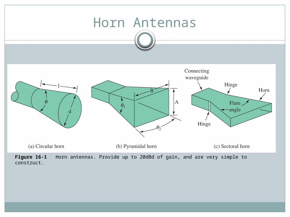
Figure 16-1 Horn antennas. Provide up to 20dBd of gain, and are very simple to construct.
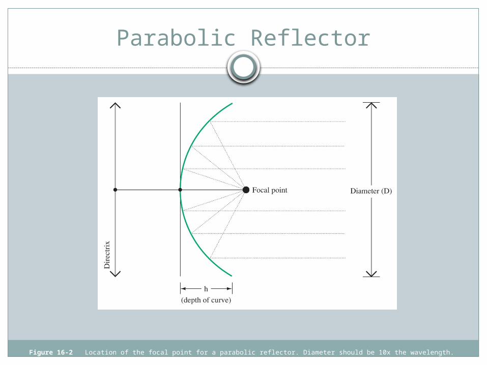
Parabolic Reflector
Figure 16-2 Location of the focal point for a parabolic reflector. Diameter should be 10x the wavelength.
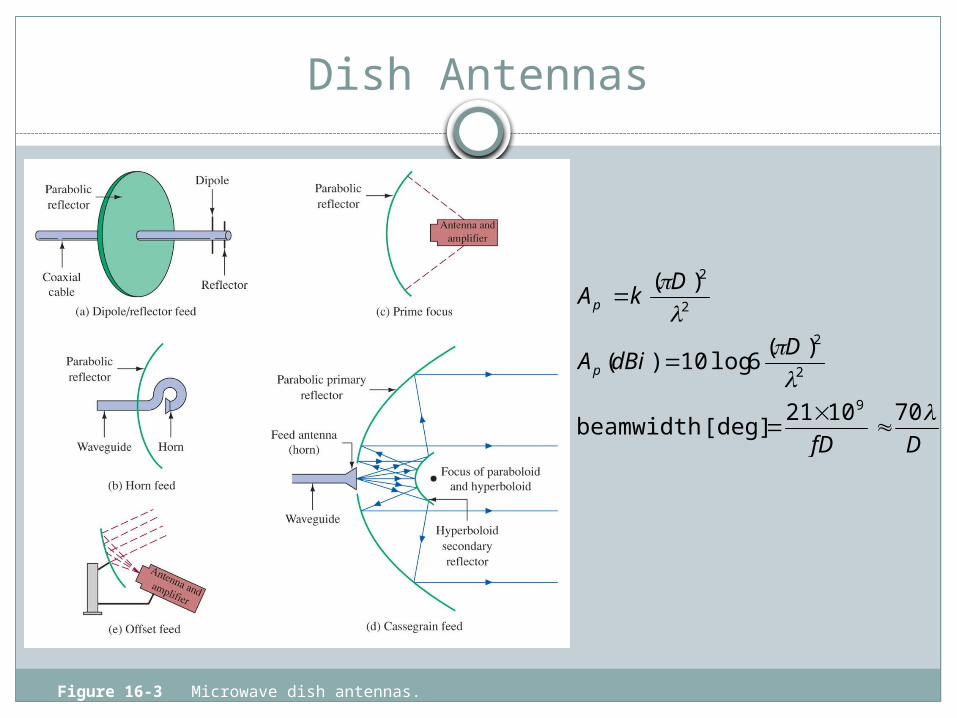
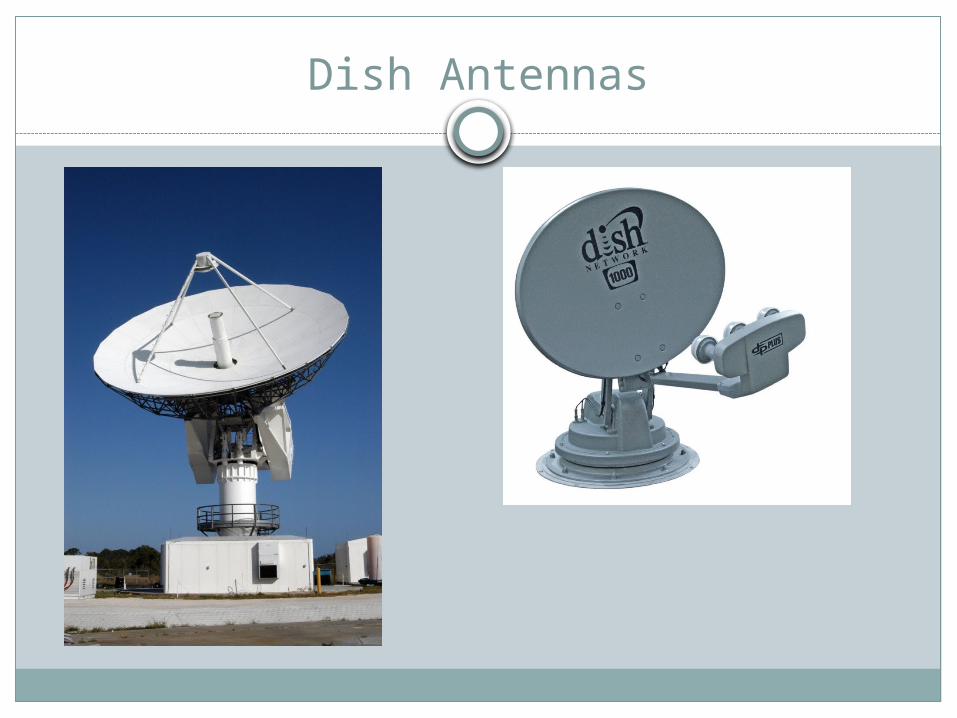
Dish Antennas
Figure 16-3 Microwave dish antennas.
DfD
DdBiA
DkA
p
p
701021[deg] beamwidth
)(6log10)(
)(
9
2
2
2
2
Dish Antennas
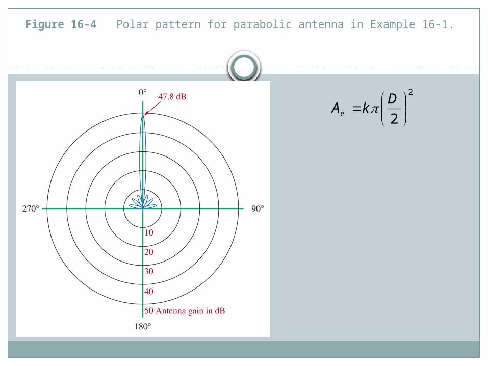
Figure 16-4 Polar pattern for parabolic antenna in Example 16-1.
2
2
D
kAe
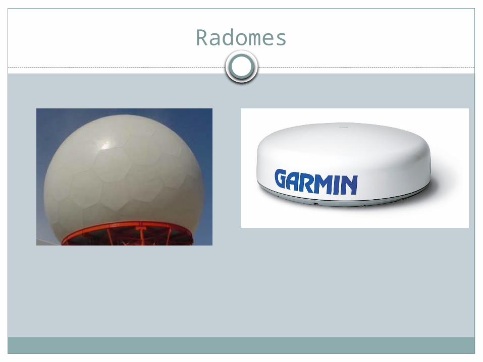
Radomes
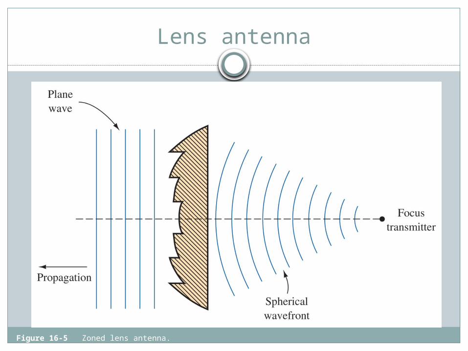
Lens antenna
Figure 16-5 Zoned lens antenna.
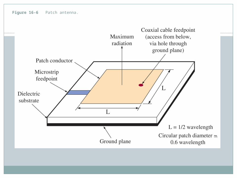
Figure 16-6 Patch antenna.
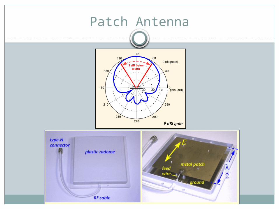
Patch Antenna
10-3 Spread-Spectrum Techniques
Modern communication are relying more and more on Spread Spectrum to make more efficient use of a single band, by making many channels within the band.
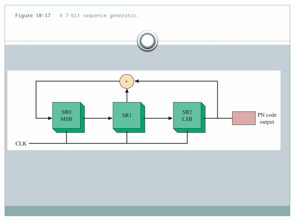
Figure 10-17 A 7-bit sequence generator.
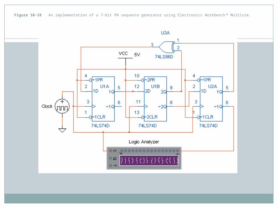
Figure 10-18 An implementation of a 7-bit PN sequence generator using Electronics WorkbenchTM Multisim.
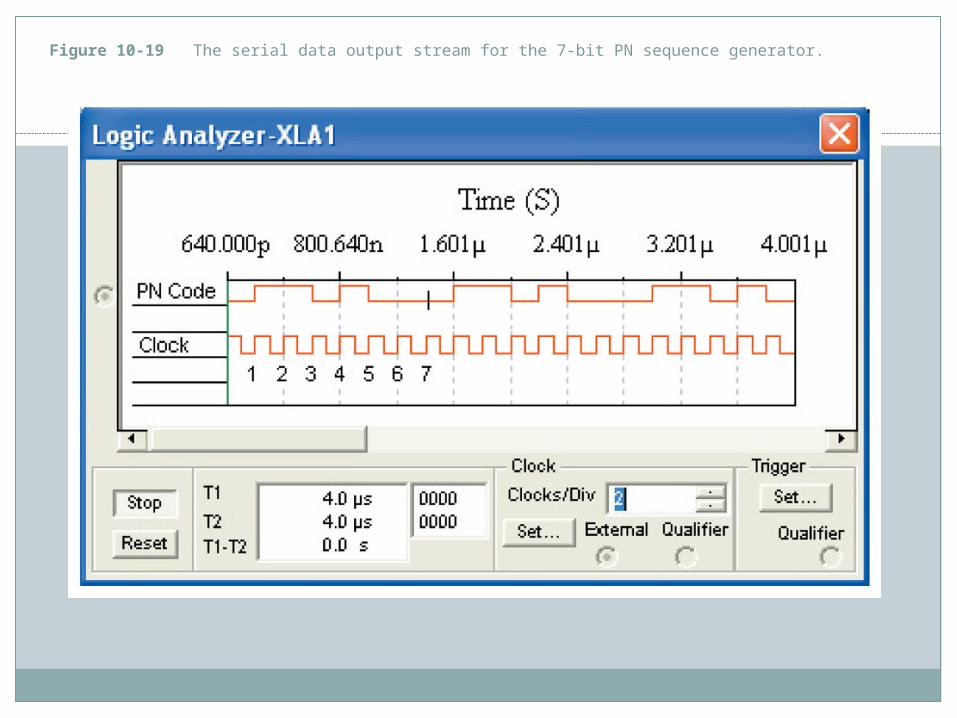
Figure 10-19 The serial data output stream for the 7-bit PN sequence generator.
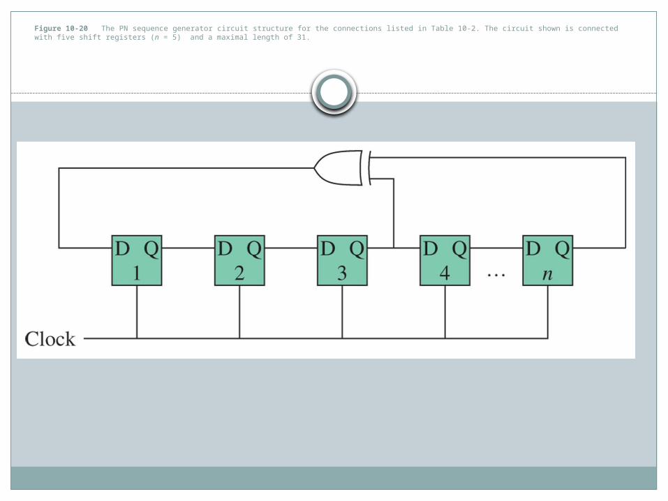
Figure 10-20 The PN sequence generator circuit structure for the connections listed in Table 10-2. The circuit shown is connected with five shift registers (n = 5) and a maximal length of 31.
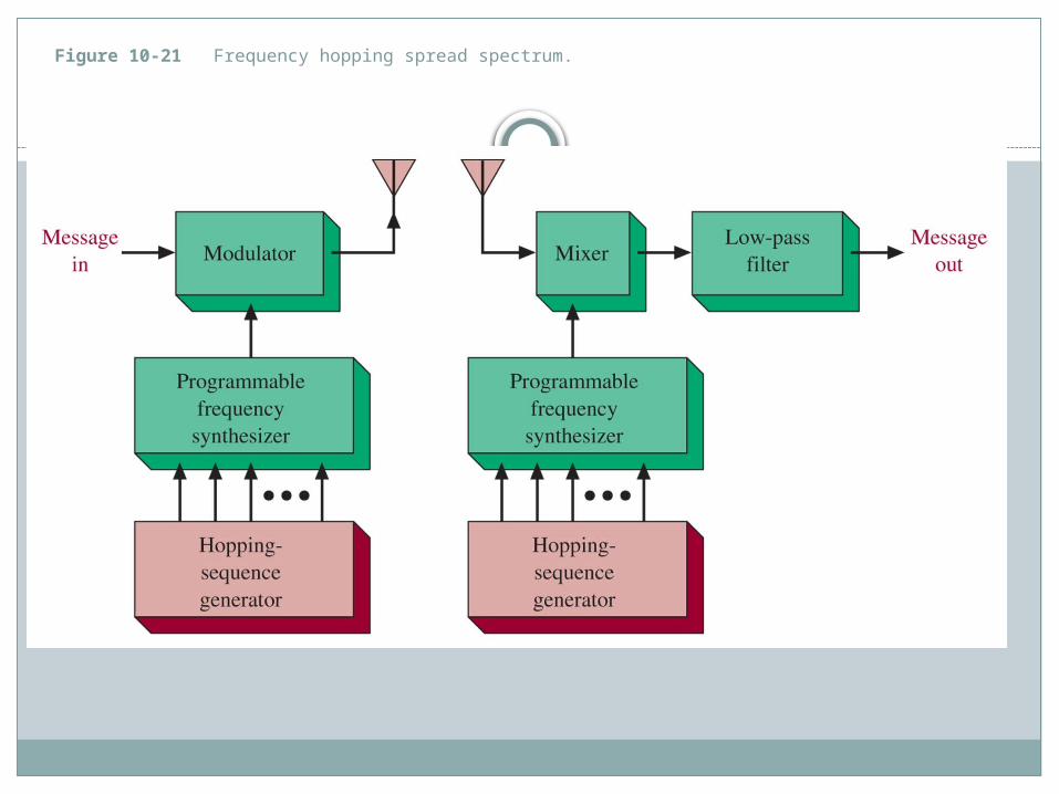
Figure 10-21 Frequency hopping spread spectrum.
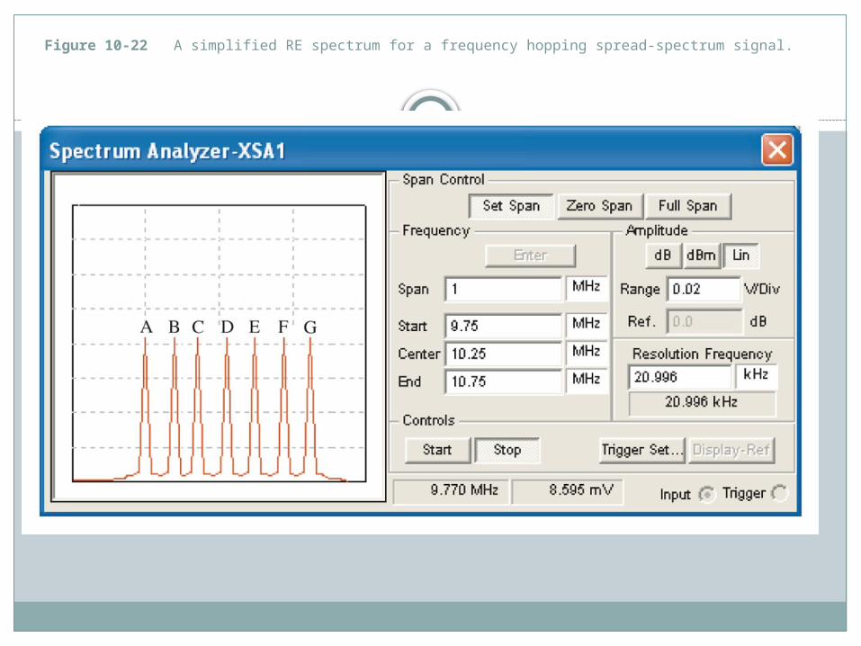
Figure 10-22 A simplified RE spectrum for a frequency hopping spread-spectrum signal.
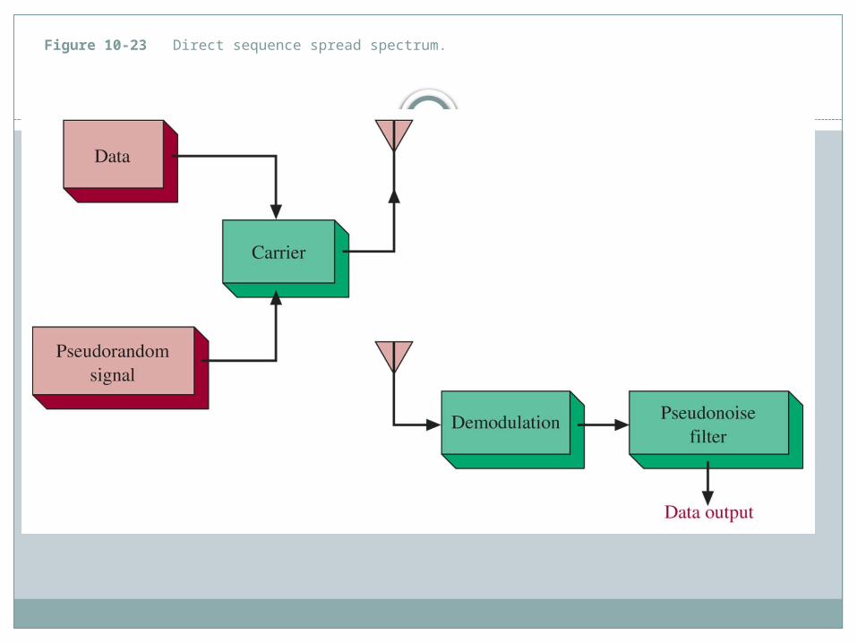
Figure 10-23 Direct sequence spread spectrum.
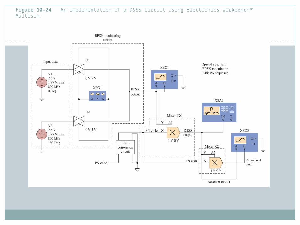
Figure 10-24 An implementation of a DSSS circuit using Electronics WorkbenchTM Multisim.
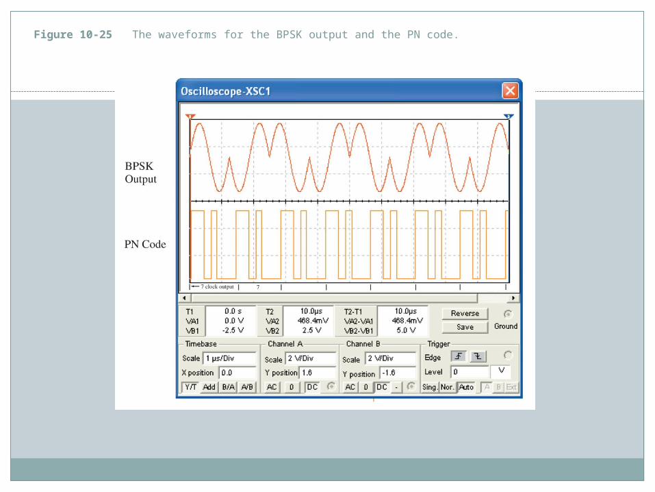
Figure 10-25 The waveforms for the BPSK output and the PN code.
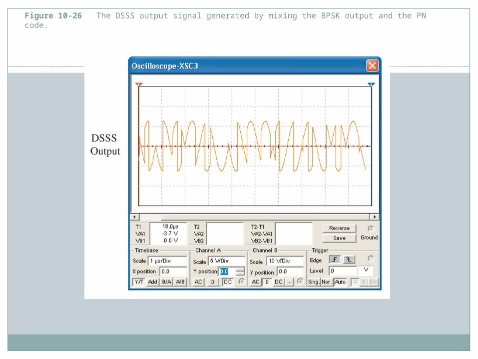
Figure 10-26 The DSSS output signal generated by mixing the BPSK output and the PN code.
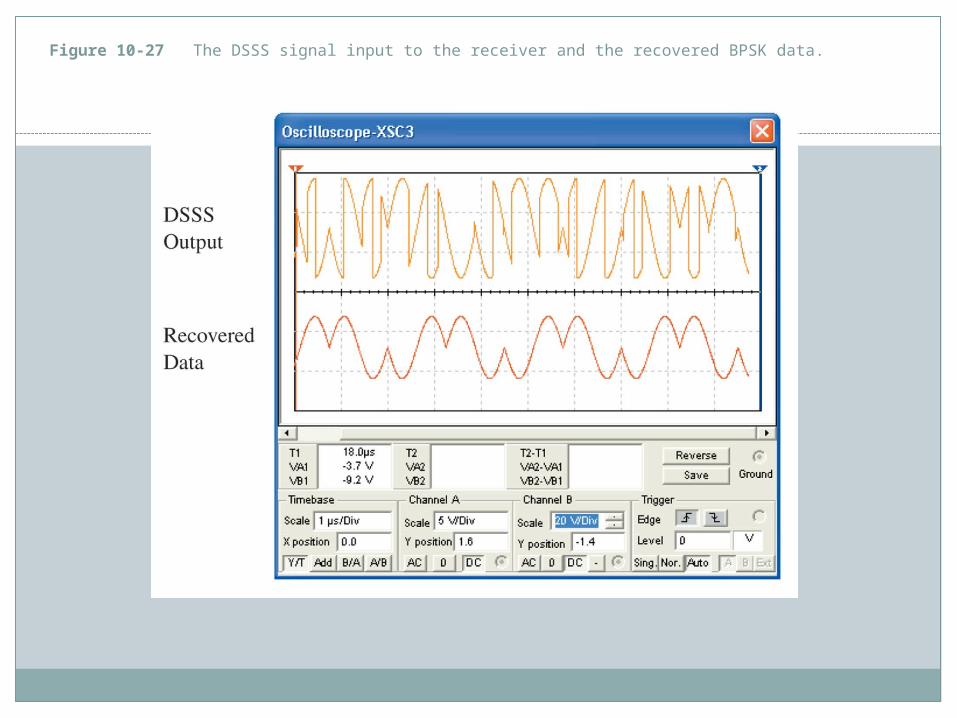
Figure 10-27 The DSSS signal input to the receiver and the recovered BPSK data.

Figure 10-28 The spectrum of the BPSK signal.

Figure 10-29 The time domain waveforms for the BPSK and PN code outputs using the proper chip modulation rate relationship.
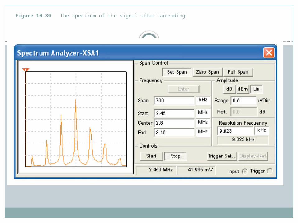
Figure 10-30 The spectrum of the signal after spreading.


![The Big Picture - Fairfield University · The Big Picture FAIRFIELD UNIVERSITYFAIRFIELD UNIVERSITY. FAIRFIELD UNIVERSITY ___ NIQZÅMTL ML] 1 Y ... Biochemistry Biology chemistry communication](https://img.pdfslide.us/doc/110x75/5f5ce6f6442979647317c439/the-big-picture-fairfield-university-the-big-picture-fairfield-universityfairfield.jpg)