Embed Size (px)
Citation preview
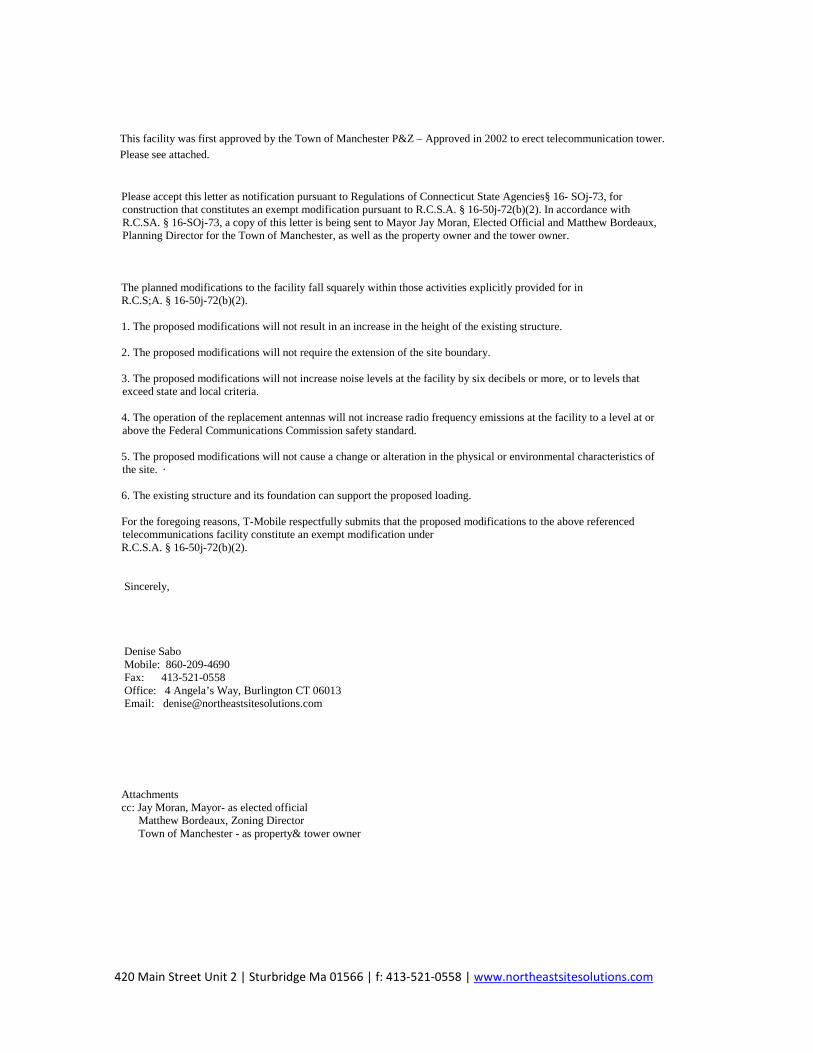
Denise Sabo 420 Main Street, Box 2 Sturbridge MA 01566
860-209-4690 [email protected]
June 13, 2018
Members of the Siting Council Connecticut Siting Council Ten Franklin Square New Britain, CT 06051
RE: Exempt Modification Application 239 East Middle Turnpike, Manchester CT 06040
Latitude: 41.78438900 Longitude: -72.51177100 T-Mobile Site#: CT11365D-L700 4x2
Dear Ms. Bachman:
T-Mobile is requesting to file an exempt modification for an existing 184-foot monopole tower located at 239 East Middle Turnpike, Manchester CT 06040. T-Mobile currently has approval for nine (9) antennas at the 163-foot level of the existing 184-foot tower. The tower and property are owned by Town of Manchester. T-Mobile now intends to install one (1) IBR1300 Dish and replace existing antenna equipment. The new dish would be installed at the 163-foot level of the tower.
Planned Modifications: Remove: NONE
Remove and Replace: (3) LNX6515 Antenna (remove) - (3) APXAARR24 Antenna 600-700 Mhz (replace) (3) AIR21 Antenna (remove) - (3) AIR3246 B66 Antenna 1900-2100 Mhz (replace) (3) TMA (remove) – TMA KRY112 144/2 (replace) (3) RRU (remove) – RRU -4449 B71 B12 (replace)
Install New: (1)IBR1300 Dish (1)Fiber line (2)CAT6 Cables
Existing to Remain: (21) 1-5/8” Coax (2) Hybrid line (3) AIR32 Antenna – 1900-2100 Mhz
This facility was first approved by the Town of Manchester P&Z – Approved in 2002 to erect telecommunication tower. Please see attached.
Please accept this letter as notification pursuant to Regulations of Connecticut State Agencies§ 16- SOj-73, for construction that constitutes an exempt modification pursuant to R.C.S.A. § 16-50j-72(b)(2). In accordance with R.C.SA. § 16-SOj-73, a copy of this letter is being sent to Mayor Jay Moran, Elected Official and Matthew Bordeaux, Planning Director for the Town of Manchester, as well as the property owner and the tower owner.
The planned modifications to the facility fall squarely within those activities explicitly provided for in R.C.S;A. § 16-50j-72(b)(2).
1. The proposed modifications will not result in an increase in the height of the existing structure.
2. The proposed modifications will not require the extension of the site boundary.
3. The proposed modifications will not increase noise levels at the facility by six decibels or more, or to levels thatexceed state and local criteria.
4. The operation of the replacement antennas will not increase radio frequency emissions at the facility to a level at orabove the Federal Communications Commission safety standard.
5. The proposed modifications will not cause a change or alteration in the physical or environmental characteristics ofthe site. ·
6. The existing structure and its foundation can support the proposed loading.
For the foregoing reasons, T-Mobile respectfully submits that the proposed modifications to the above referenced telecommunications facility constitute an exempt modification under R.C.S.A. § 16-50j-72(b)(2).
Sincerely,
Denise Sabo Mobile: 860-209-4690 Fax: 413-521-0558 Office: 4 Angela’s Way, Burlington CT 06013 Email: [email protected]
Attachments cc: Jay Moran, Mayor- as elected official
Matthew Bordeaux, Zoning Director Town of Manchester - as property& tower owner
420 Main Street Unit 2 | Sturbridge Ma 01566 | f: 413-521-0558 | www.northeastsitesolutions.com

Exhibit A

Exhibit B
Location 239 MIDDLE TURNPIKE EAST Mblu 92/ 3950/ 239/ /
Acct# 395000239 Owner MANCHESTER TOWN OF
Assessment $4,243,700 Appraisal $6,062,100
PID 10705 Building Count 2
Owner MANCHESTER TOWN OF
Address 41 CENTER ST MANCHESTER, CT 06040-5096
Sale Price $0Certificate CBook & Page
Sale Date
239 MIDDLE TURNPIKE EAST
Current Value
Appraisal
Valuation Year Improvements Land Total
2016 $5,573,900 $488,200 $6,062,100
Assessment
Valuation Year Improvements Land Total
2016 $3,901,900 $341,800 $4,243,700
Owner of Record
Ownership History
Ownership History
Owner Sale Price Certificate Book & Page Sale Date
MANCHESTER TOWN OF $0 C
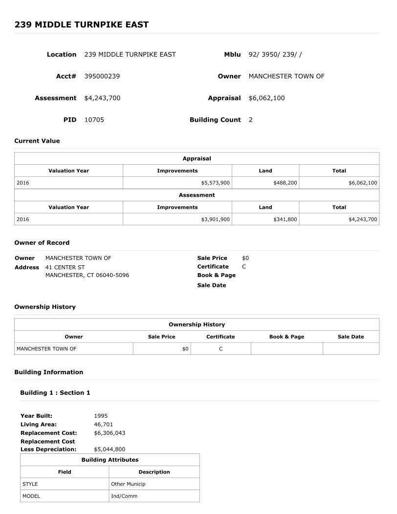
Year Built: 1995Living Area: 46,701Replacement Cost: $6,306,043Replacement Cost Less Depreciation:
$5,044,800
Building Attributes
Field Description
STYLE Other Municip
MODEL Ind/Comm
Building Information
Building 1 : Section 1
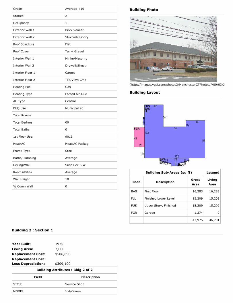
Grade Average +10
Stories: 2
Occupancy 1
Exterior Wall 1 Brick Veneer
Exterior Wall 2 Stucco/Masonry
Roof Structure Flat
Roof Cover Tar + Gravel
Interior Wall 1 Minim/Masonry
Interior Wall 2 Drywall/Sheetr
Interior Floor 1 Carpet
Interior Floor 2 Tile/Vinyl Cmp
Heating Fuel Gas
Heating Type Forced Air-Duc
AC Type Central
Bldg Use Municipal 96
Total Rooms
Total Bedrms 00
Total Baths 0
1st Floor Use: 901I
Heat/AC Heat/AC Packag
Frame Type Steel
Baths/Plumbing Average
Ceiling/Wall Susp Ceil & Wl
Rooms/Prtns Average
Wall Height 10
% Comn Wall 0
Legend
Building Photo
(http://images.vgsi.com/photos2/ManchesterCTPhotos//\00\03\2
Building Layout
Building Sub-Areas (sq ft)
Code DescriptionGross Area
Living Area
BAS First Floor 16,283 16,283
FLL Finished Lower Level 15,209 15,209
FUS Upper Story, Finished 15,209 15,209
FGR Garage 1,274 0
47,975 46,701
Year Built: 1975Living Area: 7,000Replacement Cost: $506,690Replacement Cost Less Depreciation:
$309,100
Building Attributes : Bldg 2 of 2
Field Description
STYLE Service Shop
MODEL Ind/Comm
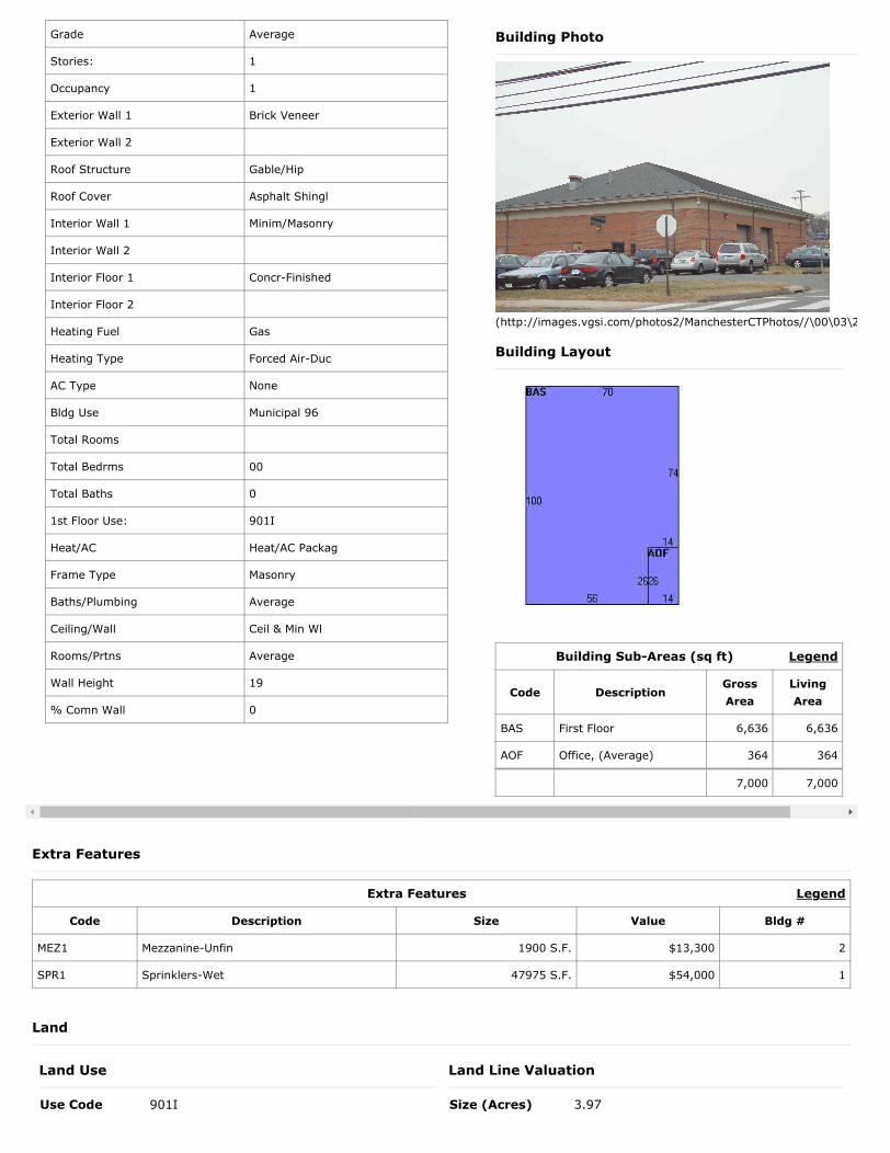
Building 2 : Section 1
Legend
Land Use
Use Code 901I
Land Line Valuation
Size (Acres) 3.97
Extra Features
Extra Features
Code Description Size Value Bldg #
MEZ1 Mezzanine-Unfin 1900 S.F. $13,300 2
SPR1 Sprinklers-Wet 47975 S.F. $54,000 1
Land
Grade Average
Stories: 1
Occupancy 1
Exterior Wall 1 Brick Veneer
Exterior Wall 2
Roof Structure Gable/Hip
Roof Cover Asphalt Shingl
Interior Wall 1 Minim/Masonry
Interior Wall 2
Interior Floor 1 Concr-Finished
Interior Floor 2
Heating Fuel Gas
Heating Type Forced Air-Duc
AC Type None
Bldg Use Municipal 96
Total Rooms
Total Bedrms 00
Total Baths 0
1st Floor Use: 901I
Heat/AC Heat/AC Packag
Frame Type Masonry
Baths/Plumbing Average
Ceiling/Wall Ceil & Min Wl
Rooms/Prtns Average
Wall Height 19
% Comn Wall 0
Legend
Building Photo
(http://images.vgsi.com/photos2/ManchesterCTPhotos//\00\03\2
Building Layout
Building Sub-Areas (sq ft)
Code DescriptionGross Area
Living Area
BAS First Floor 6,636 6,636
AOF Office, (Average) 364 364
7,000 7,000
Description Municipal 96 Zone RANeighborhood 4000Alt Land Appr NoCategory
Frontage 0Depth 0Assessed Value $341,800Appraised Value $488,200
Legend
(c) 2016 Vision Government Solutions, Inc. All rights reserved.
Outbuildings
Outbuildings
Code Description Sub Code Sub Description Size Value Bldg #
PAV1 Paving Asphalt 97700 S.F. $122,100 1
FN4 Fence 8' Chain 128 L.F. $1,900 1
LT1 Lights 1Fix 15 UNITS $12,900 1
CNP1 Canopy Ave 360 S.F. $7,800 1
SHD2 Shed W/Imp 120 S.F. $1,300 1
SHD1 Shed 168 S.F. $1,500 1
FN3 Fence 6' Chain 160 L.F. $3,700 1
SHD2 Shed W/Imp 140 S.F. $1,500 1
Valuation History
Appraisal
Valuation Year Improvements Land Total
2015 $4,365,100 $488,200 $4,853,300
2010 $4,125,100 $423,400 $4,548,500
2005 $3,622,600 $380,200 $4,002,800
Assessment
Valuation Year Improvements Land Total
2015 $3,055,600 $341,800 $3,397,400
2010 $2,887,500 $296,400 $3,183,900
2005 $2,535,800 $266,200 $2,802,000

Exhibit C
SITE IMAGE:
VICINITY MAP:
SITE
LOCATION
SITE
LOCATION
Co
pyrig
ht ©
2
01
6 F
ore
site
L
LC
a
ll rig
hts re
se
rve
d. T
he
d
eta
ils, te
mp
la
te
s, d
ra
win
g fo
rm
ats o
r a
ny p
ortio
n o
f th
is d
ocu
me
nt g
en
era
te
d b
y F
ore
site
L
LC
m
ay n
ot b
e d
up
lica
te
d, tra
ce
d o
r u
se
d o
th
erw
ise
fo
r a
ny p
ro
fit-d
rive
n e
nte
rp
rise
.
420 MAIN STREET, BLDG 4
STURBRIDGE, MA 01566
203-275-6669
462 WALNUT STREET
NEWTON, MA 02460
617-212-3123
THIS DOCUMENT IS THE DESIGN PROPERTY
AND COPYRIGHT OF FORESITE, LLC. AND
FOR THE EXCLUSIVE USE BY THE TITLE
CLIENT. DUPLICATION OR USE WITHOUT
THE EXPRESS WRITTEN CONSENT
OF THE CREATOR IS STRICTLY PROHIBITED.
DRAWING SCALES ARE INTENDED FOR
11"x17" SIZE PRINTED MEDIA ONLY. ALL
OTHER PRINTED SIZES ARE DEEMED
"NOT TO SCALE".
SITE NUMBER: CT11365D
SITE NAME: CT365/Manchester PD_MP
SITE ADDRESS: 239 E. MIDDLE TPK
MANCHESTER, CT 06040
SHEET TITLE:
REV DESCRIPTION DATE
A PRELIMINARY 03/19/18
PROFESSIONAL SEAL
PROJECT MANGER
CONSULTANT:
APPLICANT:
T-MOBILE NORTHEAST LLC
35 GRIFFIN ROAD SOUTH
BLOOMFIELD, CT 06002
860-692-7100
PROJECT NOTES:
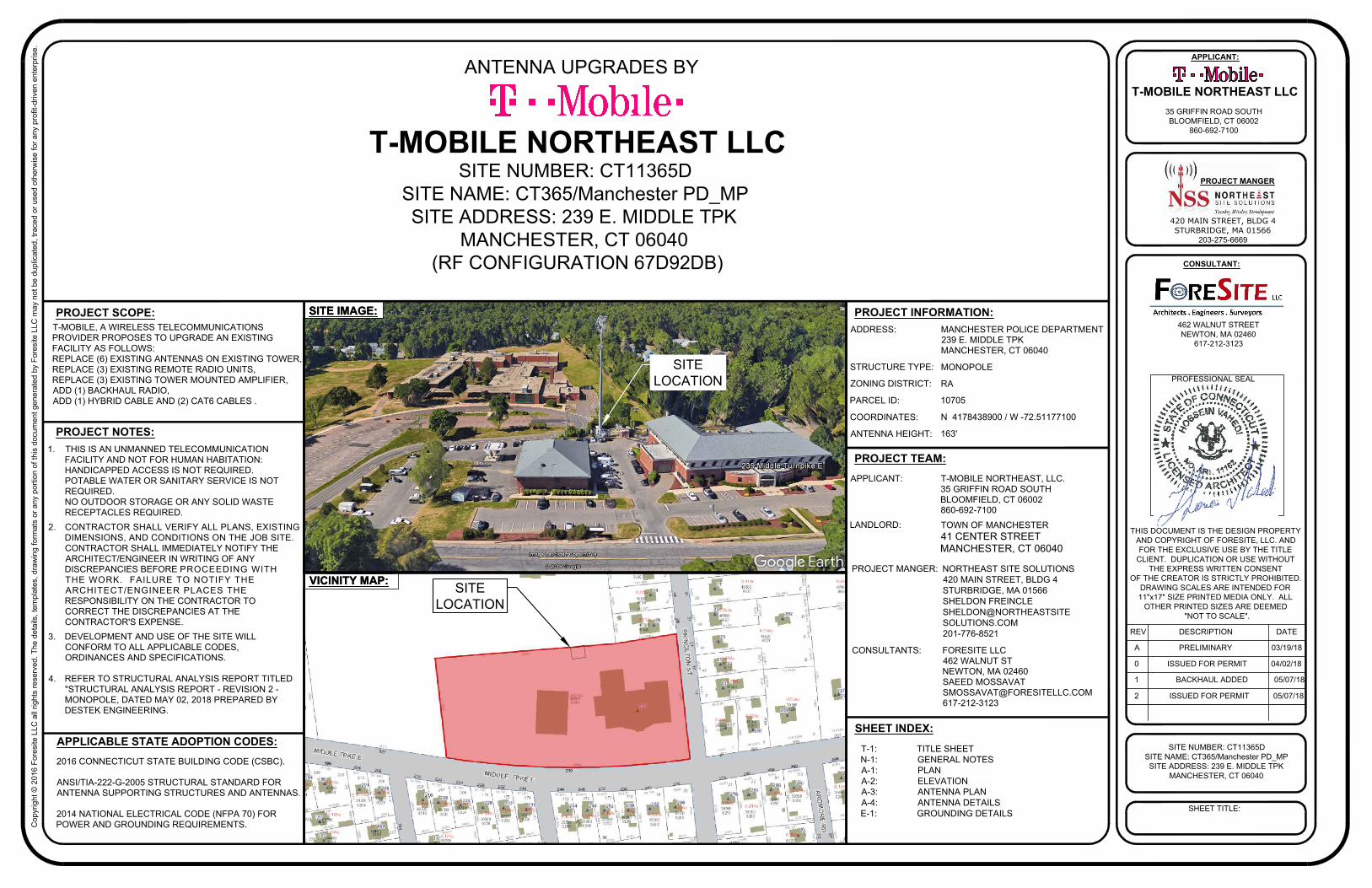
PROJECT SCOPE:
ADDRESS:
STRUCTURE TYPE:
ZONING DISTRICT:
PARCEL ID:
COORDINATES:
ANTENNA HEIGHT:
PROJECT INFORMATION:
PROJECT TEAM:
SHEET INDEX:
APPLICABLE STATE ADOPTION CODES:
2016 CONNECTICUT STATE BUILDING CODE (CSBC).
ANSI/TIA-222-G-2005 STRUCTURAL STANDARD FOR
ANTENNA SUPPORTING STRUCTURES AND ANTENNAS.
2014 NATIONAL ELECTRICAL CODE (NFPA 70) FOR
POWER AND GROUNDING REQUIREMENTS.
T-MOBILE NORTHEAST LLC
APPLICANT:
TOWN OF MANCHESTER
41 CENTER STREET
MANCHESTER, CT 06040
PROJECT MANGER:
CONSULTANTS:
LANDLORD:
SITE NUMBER: CT11365D
SITE NAME: CT365/Manchester PD_MP
SITE ADDRESS: 239 E. MIDDLE TPK
MANCHESTER, CT 06040
(RF CONFIGURATION 67D92DB)
MANCHESTER POLICE DEPARTMENT
239 E. MIDDLE TPK
MANCHESTER, CT 06040
MONOPOLE
RA
10705
N 4178438900 / W -72.51177100
163'
T-MOBILE NORTHEAST, LLC.
35 GRIFFIN ROAD SOUTH
BLOOMFIELD, CT 06002
860-692-7100
NORTHEAST SITE SOLUTIONS
420 MAIN STREET, BLDG 4
STURBRIDGE, MA 01566
SHELDON FREINCLE
SHELDON@NORTHEASTSITE
SOLUTIONS.COM
201-776-8521
FORESITE LLC
462 WALNUT ST
NEWTON, MA 02460
SAEED MOSSAVAT
617-212-3123
SITE IMAGE:
VICINITY MAP:
ANTENNA UPGRADES BY
0 ISSUED FOR PERMIT 04/02/18
1 BACKHAUL ADDED 05/07/18
1. THIS IS AN UNMANNED TELECOMMUNICATION
FACILITY AND NOT FOR HUMAN HABITATION:
HANDICAPPED ACCESS IS NOT REQUIRED.
POTABLE WATER OR SANITARY SERVICE IS NOT
REQUIRED.
NO OUTDOOR STORAGE OR ANY SOLID WASTE
RECEPTACLES REQUIRED.
2. CONTRACTOR SHALL VERIFY ALL PLANS, EXISTING
DIMENSIONS, AND CONDITIONS ON THE JOB SITE.
CONTRACTOR SHALL IMMEDIATELY NOTIFY THE
ARCHITECT/ENGINEER IN WRITING OF ANY
DISCREPANCIES BEFORE PROCEEDING WITH
THE WORK. FAILURE TO NOTIFY THE
ARCHITECT/ENGINEER PLACES THE
RESPONSIBILITY ON THE CONTRACTOR TO
CORRECT THE DISCREPANCIES AT THE
CONTRACTOR'S EXPENSE.
3. DEVELOPMENT AND USE OF THE SITE WILL
CONFORM TO ALL APPLICABLE CODES,
ORDINANCES AND SPECIFICATIONS.
4. REFER TO STRUCTURAL ANALYSIS REPORT TITLED
"STRUCTURAL ANALYSIS REPORT - REVISION 2 -
MONOPOLE, DATED MAY 02, 2018 PREPARED BY
DESTEK ENGINEERING.
T-MOBILE, A WIRELESS TELECOMMUNICATIONS
PROVIDER PROPOSES TO UPGRADE AN EXISTING
FACILITY AS FOLLOWS:
REPLACE (6) EXISTING ANTENNAS ON EXISTING TOWER,
REPLACE (3) EXISTING REMOTE RADIO UNITS,
REPLACE (3) EXISTING TOWER MOUNTED AMPLIFIER,
ADD (1) BACKHAUL RADIO,
ADD (1) HYBRID CABLE AND (2) CAT6 CABLES .
2 ISSUED FOR PERMIT 05/07/18
T-1: TITLE SHEET
N-1: GENERAL NOTES
A-1: PLAN
A-2: ELEVATION
A-3: ANTENNA PLAN
A-4: ANTENNA DETAILS
E-1: GROUNDING DETAILS
Co
pyrig
ht ©
2
01
6 F
ore
site
L
LC
a
ll rig
hts re
se
rve
d. T
he
d
eta
ils, te
mp
la
te
s, d
ra
win
g fo
rm
ats o
r a
ny p
ortio
n o
f th
is d
ocu
me
nt g
en
era
te
d b
y F
ore
site
L
LC
m
ay n
ot b
e d
up
lica
te
d, tra
ce
d o
r u
se
d o
th
erw
ise
fo
r a
ny p
ro
fit-d
rive
n e
nte
rp
rise
.
420 MAIN STREET, BLDG 4
STURBRIDGE, MA 01566
203-275-6669
462 WALNUT STREET
NEWTON, MA 02460
617-212-3123
THIS DOCUMENT IS THE DESIGN PROPERTY
AND COPYRIGHT OF FORESITE, LLC. AND
FOR THE EXCLUSIVE USE BY THE TITLE
CLIENT. DUPLICATION OR USE WITHOUT
THE EXPRESS WRITTEN CONSENT
OF THE CREATOR IS STRICTLY PROHIBITED.
DRAWING SCALES ARE INTENDED FOR
11"x17" SIZE PRINTED MEDIA ONLY. ALL
OTHER PRINTED SIZES ARE DEEMED
"NOT TO SCALE".
SITE NUMBER: CT11365D
SITE NAME: CT365/Manchester PD_MP
SITE ADDRESS: 239 E. MIDDLE TPK
MANCHESTER, CT 06040
SHEET TITLE:
REV DESCRIPTION DATE
A PRELIMINARY 03/19/18
PROFESSIONAL SEAL
PROJECT MANGER
CONSULTANT:
APPLICANT:
T-MOBILE NORTHEAST LLC
35 GRIFFIN ROAD SOUTH
BLOOMFIELD, CT 06002
860-692-7100
0 ISSUED FOR PERMIT 04/02/18
1 BACKHAUL ADDED 05/07/18
2 ISSUED FOR PERMIT 05/07/18
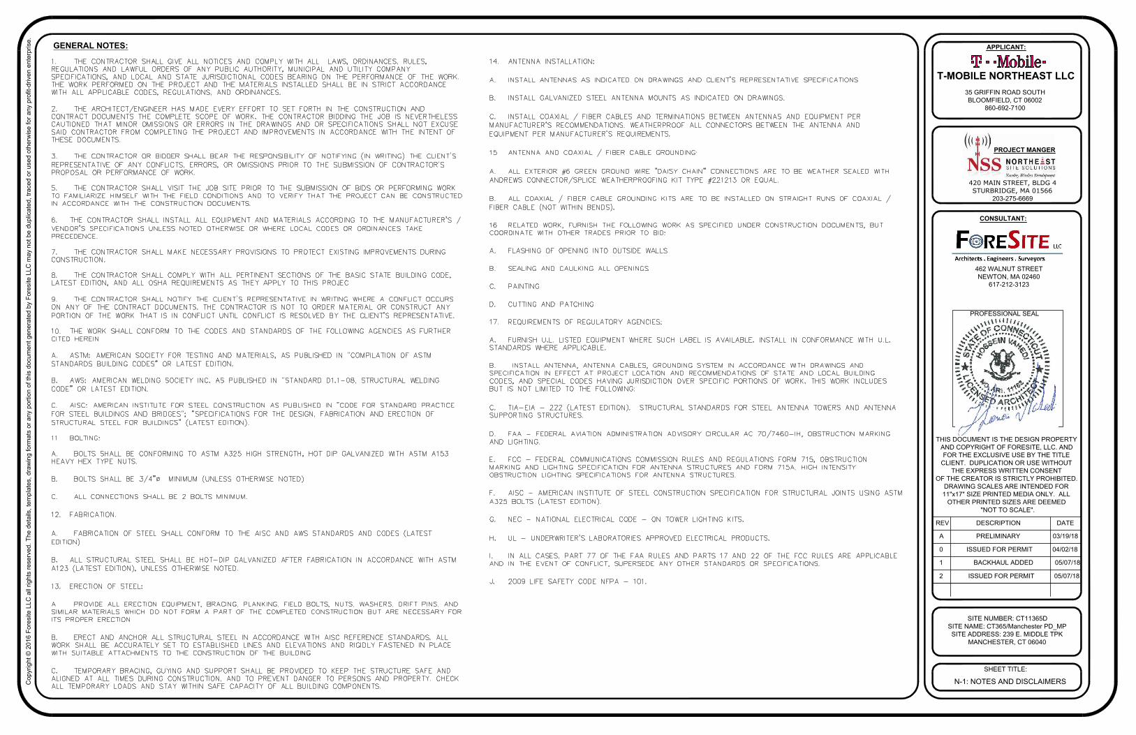
GENERAL NOTES:
N-1: NOTES AND DISCLAIMERS
Co
pyrig
ht ©
2
01
6 F
ore
site
L
LC
a
ll rig
hts re
se
rve
d. T
he
d
eta
ils, te
mp
la
te
s, d
ra
win
g fo
rm
ats o
r a
ny p
ortio
n o
f th
is d
ocu
me
nt g
en
era
te
d b
y F
ore
site
L
LC
m
ay n
ot b
e d
up
lica
te
d, tra
ce
d o
r u
se
d o
th
erw
ise
fo
r a
ny p
ro
fit-d
rive
n e
nte
rp
rise
.
420 MAIN STREET, BLDG 4
STURBRIDGE, MA 01566
203-275-6669
462 WALNUT STREET
NEWTON, MA 02460
617-212-3123
THIS DOCUMENT IS THE DESIGN PROPERTY
AND COPYRIGHT OF FORESITE, LLC. AND
FOR THE EXCLUSIVE USE BY THE TITLE
CLIENT. DUPLICATION OR USE WITHOUT
THE EXPRESS WRITTEN CONSENT
OF THE CREATOR IS STRICTLY PROHIBITED.
DRAWING SCALES ARE INTENDED FOR
11"x17" SIZE PRINTED MEDIA ONLY. ALL
OTHER PRINTED SIZES ARE DEEMED
"NOT TO SCALE".
SITE NUMBER: CT11365D
SITE NAME: CT365/Manchester PD_MP
SITE ADDRESS: 239 E. MIDDLE TPK
MANCHESTER, CT 06040
SHEET TITLE:
REV DESCRIPTION DATE
A PRELIMINARY 03/19/18
PROFESSIONAL SEAL
PROJECT MANGER
CONSULTANT:
APPLICANT:
T-MOBILE NORTHEAST LLC
35 GRIFFIN ROAD SOUTH
BLOOMFIELD, CT 06002
860-692-7100
0 ISSUED FOR PERMIT 04/02/18
1 BACKHAUL ADDED 05/07/18
2 ISSUED FOR PERMIT 05/07/18
A-1: PLAN
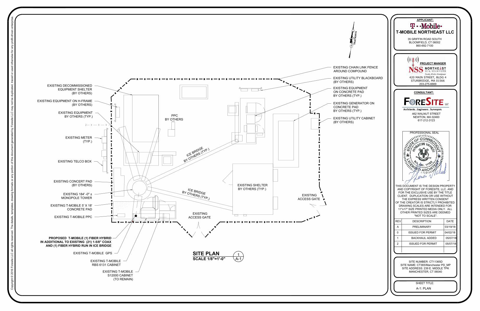
SCALE 1/8"=1'-0"
SITE PLAN
A-1
1
EXISTING SHELTER
BY OTHERS (TYP.)
EXISTING GENERATOR ON
CONCRETE PAD
BY OTHERS (TYP.)
EXISTING UTILITY BLACKBOARD
(BY OTHERS)
EXISTING UTILITY CABINET
(BY OTHERS)
EXISTING DECOMMISSIONED
EQUIPMENT SHELTER
(BY OTHERS)
EXISTING EQUIPMENT ON H-FRAME
(BY OTHERS)
EXISTING METER
(TYP.)
EXISTING TELCO BOX
EXISTING CONCERT PAD
(BY OTHERS)
EXISTING 184' -0" ±
MONOPOLE TOWER
EXISTING T-MOBILE 5' X 18'
CONCRETE PAD
EXISTING T-MOBILE PPC
EXISTING
ACCESS GATE
EXISTING
ACCESS GATE
I
C
E
B
R
I
D
G
E
B
Y
O
T
H
E
R
S
(
T
Y
P
.
)
IC
E
B
R
ID
G
E
B
Y
O
T
H
E
R
S
(T
Y
P
.)
PPC
BY OTHERS
EXISTING EQUIPMENT
ON CONCRETE PAD
BY OTHERS (TYP.)
EXISTING EQUIPMENT
BY OTHERS (TYP.)
EXISTING CHAIN LINK FENCE
AROUND COMPOUND
TR
U
E N
O
R
TH
PROPOSED T-MOBILE (1) FIBER HYBRID
IN ADDITIONAL TO EXISTING (21) 1-5/8" COAX
AND (1) FIBER HYBRID RUN IN ICE BRIDGE
EXISTING T-MOBILE
RBS 6131 CABINET
EXISTING T-MOBILE
S12000 CABINET
(TO REMAIN)
EXISTING T-MOBILE GPS
Co
pyrig
ht ©
2
01
6 F
ore
site
L
LC
a
ll rig
hts re
se
rve
d. T
he
d
eta
ils, te
mp
la
te
s, d
ra
win
g fo
rm
ats o
r a
ny p
ortio
n o
f th
is d
ocu
me
nt g
en
era
te
d b
y F
ore
site
L
LC
m
ay n
ot b
e d
up
lica
te
d, tra
ce
d o
r u
se
d o
th
erw
ise
fo
r a
ny p
ro
fit-d
rive
n e
nte
rp
rise
.
420 MAIN STREET, BLDG 4
STURBRIDGE, MA 01566
203-275-6669
462 WALNUT STREET
NEWTON, MA 02460
617-212-3123
THIS DOCUMENT IS THE DESIGN PROPERTY
AND COPYRIGHT OF FORESITE, LLC. AND
FOR THE EXCLUSIVE USE BY THE TITLE
CLIENT. DUPLICATION OR USE WITHOUT
THE EXPRESS WRITTEN CONSENT
OF THE CREATOR IS STRICTLY PROHIBITED.
DRAWING SCALES ARE INTENDED FOR
11"x17" SIZE PRINTED MEDIA ONLY. ALL
OTHER PRINTED SIZES ARE DEEMED
"NOT TO SCALE".
SITE NUMBER: CT11365D
SITE NAME: CT365/Manchester PD_MP
SITE ADDRESS: 239 E. MIDDLE TPK
MANCHESTER, CT 06040
SHEET TITLE:
REV DESCRIPTION DATE
A PRELIMINARY 03/19/18
PROFESSIONAL SEAL
PROJECT MANGER
CONSULTANT:
APPLICANT:
T-MOBILE NORTHEAST LLC
35 GRIFFIN ROAD SOUTH
BLOOMFIELD, CT 06002
860-692-7100
0 ISSUED FOR PERMIT 04/02/18
1 BACKHAUL ADDED 05/07/18
2 ISSUED FOR PERMIT 05/07/18
A-2: ELEVATION
SCALE: NTS
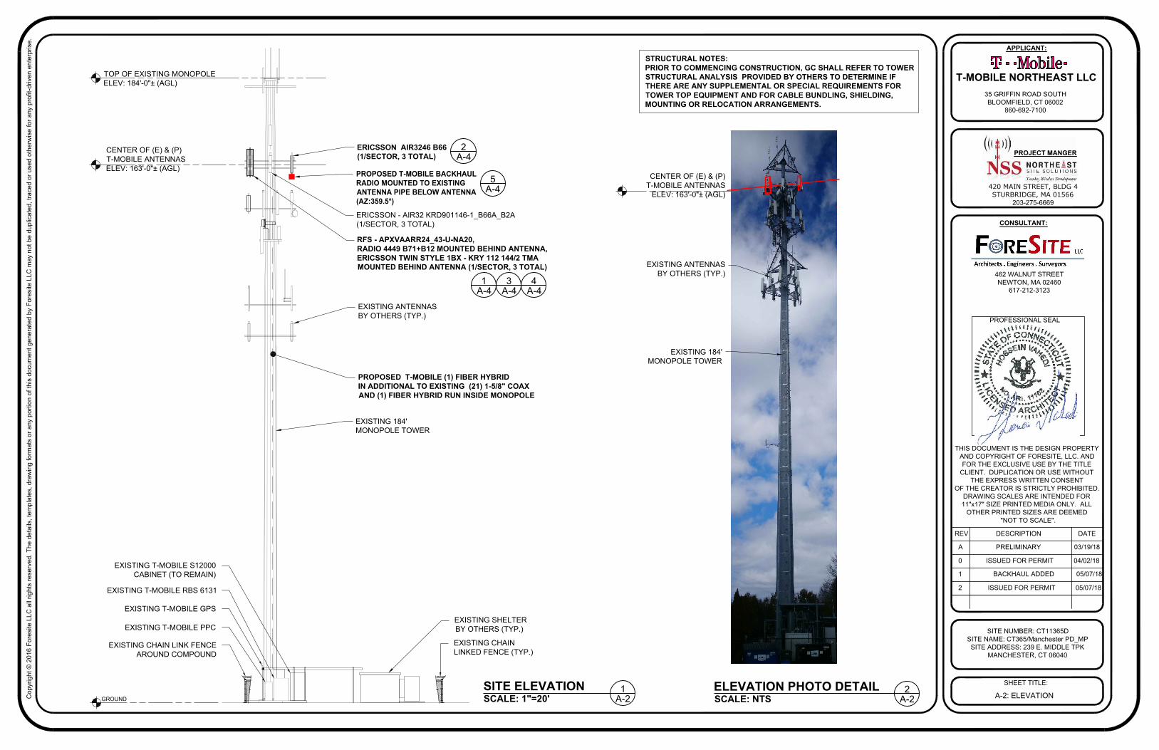
ELEVATION PHOTO DETAIL
A-2
2
EXISTING 184'
MONOPOLE TOWER
EXISTING ANTENNAS
BY OTHERS (TYP.)
SCALE: 1"=20'
SITE ELEVATION
A-2
1
TOP OF EXISTING MONOPOLE
ELEV: 184'-0"± (AGL)
CENTER OF (E) & (P)
T-MOBILE ANTENNAS
ELEV: 163'-0"± (AGL)
EXISTING ANTENNAS
BY OTHERS (TYP.)
GROUND
PROPOSED T-MOBILE (1) FIBER HYBRID
IN ADDITIONAL TO EXISTING (21) 1-5/8" COAX
AND (1) FIBER HYBRID RUN INSIDE MONOPOLE
STRUCTURAL NOTES:
PRIOR TO COMMENCING CONSTRUCTION, GC SHALL REFER TO TOWER
STRUCTURAL ANALYSIS PROVIDED BY OTHERS TO DETERMINE IF
THERE ARE ANY SUPPLEMENTAL OR SPECIAL REQUIREMENTS FOR
TOWER TOP EQUIPMENT AND FOR CABLE BUNDLING, SHIELDING,
MOUNTING OR RELOCATION ARRANGEMENTS.
EXISTING SHELTER
BY OTHERS (TYP.)
EXISTING CHAIN
LINKED FENCE (TYP.)
EXISTING CHAIN LINK FENCE
AROUND COMPOUND
EXISTING T-MOBILE PPC
EXISTING T-MOBILE RBS 6131
EXISTING T-MOBILE GPS
EXISTING T-MOBILE S12000
CABINET (TO REMAIN)
CENTER OF (E) & (P)
T-MOBILE ANTENNAS
ELEV: 163'-0"± (AGL)
EXISTING 184'
MONOPOLE TOWER
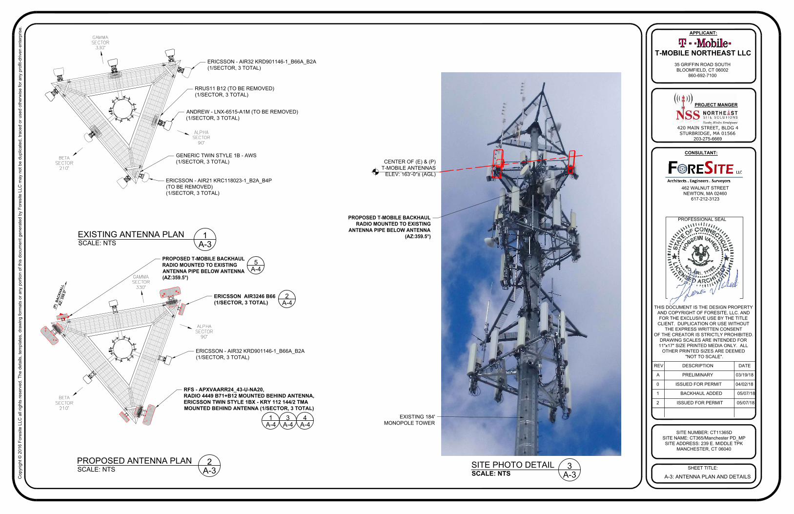
PROPOSED T-MOBILE BACKHAUL
RADIO MOUNTED TO EXISTING
ANTENNA PIPE BELOW ANTENNA
(AZ:359.5°)
A-4
5
ERICSSON - AIR32 KRD901146-1_B66A_B2A
(1/SECTOR, 3 TOTAL)
ERICSSON AIR3246 B66
(1/SECTOR, 3 TOTAL)
RFS - APXVAARR24_43-U-NA20,
RADIO 4449 B71+B12 MOUNTED BEHIND ANTENNA,
ERICSSON TWIN STYLE 1BX - KRY 112 144/2 TMA
MOUNTED BEHIND ANTENNA (1/SECTOR, 3 TOTAL)
A-4
1
A-4
3
A-4
4
A-4
2
Co
pyrig
ht ©
2
01
6 F
ore
site
L
LC
a
ll rig
hts re
se
rve
d. T
he
d
eta
ils, te
mp
la
te
s, d
ra
win
g fo
rm
ats o
r a
ny p
ortio
n o
f th
is d
ocu
me
nt g
en
era
te
d b
y F
ore
site
L
LC
m
ay n
ot b
e d
up
lica
te
d, tra
ce
d o
r u
se
d o
th
erw
ise
fo
r a
ny p
ro
fit-d
rive
n e
nte
rp
rise
.
420 MAIN STREET, BLDG 4
STURBRIDGE, MA 01566
203-275-6669
462 WALNUT STREET
NEWTON, MA 02460
617-212-3123
THIS DOCUMENT IS THE DESIGN PROPERTY
AND COPYRIGHT OF FORESITE, LLC. AND
FOR THE EXCLUSIVE USE BY THE TITLE
CLIENT. DUPLICATION OR USE WITHOUT
THE EXPRESS WRITTEN CONSENT
OF THE CREATOR IS STRICTLY PROHIBITED.
DRAWING SCALES ARE INTENDED FOR
11"x17" SIZE PRINTED MEDIA ONLY. ALL
OTHER PRINTED SIZES ARE DEEMED
"NOT TO SCALE".
SITE NUMBER: CT11365D
SITE NAME: CT365/Manchester PD_MP
SITE ADDRESS: 239 E. MIDDLE TPK
MANCHESTER, CT 06040
SHEET TITLE:
REV DESCRIPTION DATE
A PRELIMINARY 03/19/18
PROFESSIONAL SEAL
PROJECT MANGER
CONSULTANT:
APPLICANT:
T-MOBILE NORTHEAST LLC
35 GRIFFIN ROAD SOUTH
BLOOMFIELD, CT 06002
860-692-7100
0 ISSUED FOR PERMIT 04/02/18
1 BACKHAUL ADDED 05/07/18
2 ISSUED FOR PERMIT 05/07/18
A-3: ANTENNA PLAN AND DETAILS
(
P
)
B
A
C
K
H
A
L
L
A
Z
:
3
5
9
.
5
°
ERICSSON - AIR32 KRD901146-1_B66A_B2A
(1/SECTOR, 3 TOTAL)
ERICSSON - AIR21 KRC118023-1_B2A_B4P
(TO BE REMOVED)
(1/SECTOR, 3 TOTAL)
GENERIC TWIN STYLE 1B - AWS
(1/SECTOR, 3 TOTAL)
ANDREW - LNX-6515-A1M (TO BE REMOVED)
(1/SECTOR, 3 TOTAL)
RRUS11 B12 (TO BE REMOVED)
(1/SECTOR, 3 TOTAL)
SCALE: NTS
EXISTING ANTENNA PLAN
A-3
1
SCALE: NTS
PROPOSED ANTENNA PLAN
A-3
2
SCALE: NTS
SITE PHOTO DETAIL
EXISTING 184'
MONOPOLE TOWER
CENTER OF (E) & (P)
T-MOBILE ANTENNAS
ELEV: 163'-0"± (AGL)
PROPOSED T-MOBILE BACKHAUL
RADIO MOUNTED TO EXISTING
ANTENNA PIPE BELOW ANTENNA
(AZ:359.5°)
PROPOSED T-MOBILE BACKHAUL
RADIO MOUNTED TO EXISTING
ANTENNA PIPE BELOW ANTENNA
(AZ:359.5°)
A-4
5
ERICSSON - AIR32 KRD901146-1_B66A_B2A
(1/SECTOR, 3 TOTAL)
ERICSSON AIR3246 B66
(1/SECTOR, 3 TOTAL)
RFS - APXVAARR24_43-U-NA20,
RADIO 4449 B71+B12 MOUNTED BEHIND ANTENNA,
ERICSSON TWIN STYLE 1BX - KRY 112 144/2 TMA
MOUNTED BEHIND ANTENNA (1/SECTOR, 3 TOTAL)
A-4
1
A-4
3
A-4
4
A-4
2
A-3
3
Co
pyrig
ht ©
2
01
6 F
ore
site
L
LC
a
ll rig
hts re
se
rve
d. T
he
d
eta
ils, te
mp
la
te
s, d
ra
win
g fo
rm
ats o
r a
ny p
ortio
n o
f th
is d
ocu
me
nt g
en
era
te
d b
y F
ore
site
L
LC
m
ay n
ot b
e d
up
lica
te
d, tra
ce
d o
r u
se
d o
th
erw
ise
fo
r a
ny p
ro
fit-d
rive
n e
nte
rp
rise
.
420 MAIN STREET, BLDG 4
STURBRIDGE, MA 01566
203-275-6669
462 WALNUT STREET
NEWTON, MA 02460
617-212-3123
THIS DOCUMENT IS THE DESIGN PROPERTY
AND COPYRIGHT OF FORESITE, LLC. AND
FOR THE EXCLUSIVE USE BY THE TITLE
CLIENT. DUPLICATION OR USE WITHOUT
THE EXPRESS WRITTEN CONSENT
OF THE CREATOR IS STRICTLY PROHIBITED.
DRAWING SCALES ARE INTENDED FOR
11"x17" SIZE PRINTED MEDIA ONLY. ALL
OTHER PRINTED SIZES ARE DEEMED
"NOT TO SCALE".
SITE NUMBER: CT11365D
SITE NAME: CT365/Manchester PD_MP
SITE ADDRESS: 239 E. MIDDLE TPK
MANCHESTER, CT 06040
SHEET TITLE:
REV DESCRIPTION DATE
A PRELIMINARY 03/19/18
PROFESSIONAL SEAL
PROJECT MANGER
CONSULTANT:
APPLICANT:
T-MOBILE NORTHEAST LLC
35 GRIFFIN ROAD SOUTH
BLOOMFIELD, CT 06002
860-692-7100
0 ISSUED FOR PERMIT 04/02/18
1 BACKHAUL ADDED 05/07/18
2 ISSUED FOR PERMIT 05/07/18
A-4: ANTENNA DETAILS
W
H
D
D
W
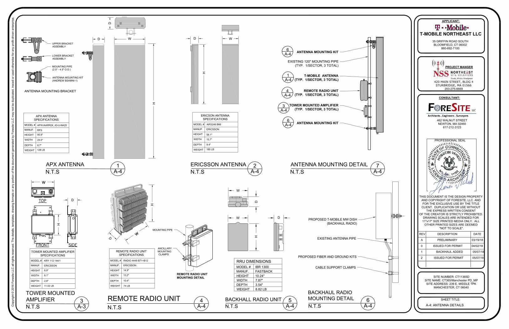
PROPOSED T-MOBILE MW DISH
(BACKHAUL RADIO)
EXISTING ANTENNA PIPE
PROPOSED FIBER AND GROUND KITS
CABLE SUPPORT CLAMPS
6
A-4
BACKHAUL RADIO
MOUNTING DETAIL
N.T.S
MODEL #
MANUF.
HEIGHT
DEPTH
8.82 LBWEIGHT
WIDTH
3.54"
7.87"
10.24"
FASTBACK
IBR 1300
RRU DIMENSIONS
5
A-4
BACKHALL RADIO UNIT
N.T.S
D
H
w
74 LB
10.4"
13.2"
14.9"
ERICSSON
RADIO 4449 B71+B12
REMOTE RADIO UNIT
SPECIFICATIONS
REMOTE RADIO UNIT
N.T.S
T-MOBILE ANTENNA
(TYP. 1/SECTOR, 3 TOTAL)
REMOTE RADIO UNIT
(TYP. 1/SECTOR, 3 TOTAL)
A-4
4
EXISTING 120" MOUNTING PIPE
(TYP. 1/SECTOR, 3 TOTAL)
ANTENNA MOUNTING KIT
ANTENNA MOUNTING KIT
A-4
6
REMOTE RADIO UNIT
MOUNTING DETAIL
ANCILLARY
MOUNTING
CLAMPS
MOUNTING PIPE
UPPER BRACKET
ASSEMBLY
LOWER BRACKET
ASSEMBLY
MOUNTING PIPE
(2.5" - 4.5" O.D.)
ANTENNA MOUNTING KIT
(ANDREW BSAMNI-1)
ANTENNA MOUNTING BRACKET
1
A-4
APX ANTENNA
N.T.S
D
H
W
128 LB
8.7"
24.0"
95.9"
RFS
MODEL #
MANUF.
HEIGHT
DEPTH
WEIGHT
WIDTH
APX ANTENNA
SPECIFICATIONS
D
APXVAARR24_43-U-NA20
11.02 LB
2.8"
6.1"
6.9"
ERICSSON
KRY 112 144/1
3
A-3
TOWER MOUNTED
AMPLIFIER
N.T.S
w
H
D
MODEL #
MANUF.
HEIGHT
DEPTH
WEIGHT
WIDTH
TOWER MOUNTED AMPLIFIER
SPECIFICATIONS
2
A-4
ERICSSON ANTENNA
N.T.S
D
H
W
180 LB
9.4"
15.7"
58.1"
ERICSSON
AIR3246 B66MODEL #
MANUF.
HEIGHT
DEPTH
WEIGHT
WIDTH
ERICSON ANTENNA
SPECIFICATIONS
MODEL #
MANUF.
HEIGHT
DEPTH
WEIGHT
WIDTH
4
A-4
7
A-4
ANTENNA MOUNTING DETAIL
N.T.S
A-4
6
A-4
1
TOWER MOUNTED AMPLIFIER
(TYP. 1/SECTOR, 3 TOTAL)
A-4
3
Co
pyrig
ht ©
2
01
6 F
ore
site
L
LC
a
ll rig
hts re
se
rve
d. T
he
d
eta
ils, te
mp
la
te
s, d
ra
win
g fo
rm
ats o
r a
ny p
ortio
n o
f th
is d
ocu
me
nt g
en
era
te
d b
y F
ore
site
L
LC
m
ay n
ot b
e d
up
lica
te
d, tra
ce
d o
r u
se
d o
th
erw
ise
fo
r a
ny p
ro
fit-d
rive
n e
nte
rp
rise
.
420 MAIN STREET, BLDG 4
STURBRIDGE, MA 01566
203-275-6669
462 WALNUT STREET
NEWTON, MA 02460
617-212-3123
THIS DOCUMENT IS THE DESIGN PROPERTY
AND COPYRIGHT OF FORESITE, LLC. AND
FOR THE EXCLUSIVE USE BY THE TITLE
CLIENT. DUPLICATION OR USE WITHOUT
THE EXPRESS WRITTEN CONSENT
OF THE CREATOR IS STRICTLY PROHIBITED.
DRAWING SCALES ARE INTENDED FOR
11"x17" SIZE PRINTED MEDIA ONLY. ALL
OTHER PRINTED SIZES ARE DEEMED
"NOT TO SCALE".
SITE NUMBER: CT11365D
SITE NAME: CT365/Manchester PD_MP
SITE ADDRESS: 239 E. MIDDLE TPK
MANCHESTER, CT 06040
SHEET TITLE:
REV DESCRIPTION DATE
A PRELIMINARY 03/19/18
PROFESSIONAL SEAL
PROJECT MANGER
CONSULTANT:
APPLICANT:
T-MOBILE NORTHEAST LLC
35 GRIFFIN ROAD SOUTH
BLOOMFIELD, CT 06002
860-692-7100
0 ISSUED FOR PERMIT 04/02/18
1 BACKHAUL ADDED 05/07/18
2 ISSUED FOR PERMIT 05/07/18
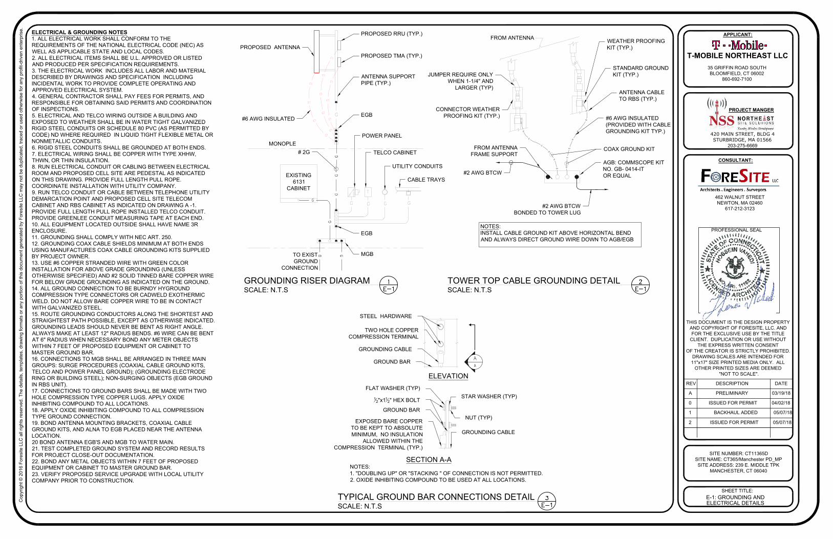
NOTES:
1. "DOUBLING UP" OR "STACKING " OF CONNECTION IS NOT PERMITTED.
2. OXIDE INHIBITING COMPOUND TO BE USED AT ALL LOCATIONS.
STEEL HARDWARE
GROUND BAR
STAR WASHER (TYP)
NUT (TYP)
GROUNDING CABLE
GROUNDING CABLE
FLAT WASHER (TYP)
1
2
"x1
1
2
" HEX BOLT
GROUND BAR
EXPOSED BARE COPPER
TO BE KEPT TO ABSOLUTE
MINIMUM, NO INSULATION
ALLOWED WITHIN THE
COMPRESSION TERMINAL (TYP.)
SECTION A-A
TYPICAL GROUND BAR CONNECTIONS DETAIL
SCALE: N.T.S
TWO HOLE COPPER
COMPRESSION TERMINAL
ELEVATION
ELECTRICAL & GROUNDING NOTES
1. ALL ELECTRICAL WORK SHALL CONFORM TO THE
REQUIREMENTS OF THE NATIONAL ELECTRICAL CODE (NEC) AS
WELL AS APPLICABLE STATE AND LOCAL CODES.
2. ALL ELECTRICAL ITEMS SHALL BE U.L. APPROVED OR LISTED
AND PRODUCED PER SPECIFICATION REQUIREMENTS.
3. THE ELECTRICAL WORK INCLUDES ALL LABOR AND MATERIAL
DESCRIBED BY DRAWINGS AND SPECIFICATION INCLUDING
INCIDENTAL WORK TO PROVIDE COMPLETE OPERATING AND
APPROVED ELECTRICAL SYSTEM.
4. GENERAL CONTRACTOR SHALL PAY FEES FOR PERMITS, AND
RESPONSIBLE FOR OBTAINING SAID PERMITS AND COORDINATION
OF INSPECTIONS.
5. ELECTRICAL AND TELCO WIRING OUTSIDE A BUILDING AND
EXPOSED TO WEATHER SHALL BE IN WATER TIGHT GALVANIZED
RIGID STEEL CONDUITS OR SCHEDULE 80 PVC (AS PERMITTED BY
CODE) ND WHERE REQUIRED IN LIQUID TIGHT FLEXIBLE METAL OR
NONMETALLIC CONDUITS.
6. RIGID STEEL CONDUITS SHALL BE GROUNDED AT BOTH ENDS.
7. ELECTRICAL WIRING SHALL BE COPPER WITH TYPE XHHW,
THWN, OR THIN INSULATION.
8. RUN ELECTRICAL CONDUIT OR CABLING BETWEEN ELECTRICAL
ROOM AND PROPOSED CELL SITE ARE PEDESTAL AS INDICATED
ON THIS DRAWING. PROVIDE FULL LENGTH PULL ROPE.
COORDINATE INSTALLATION WITH UTILITY COMPANY.
9. RUN TELCO CONDUIT OR CABLE BETWEEN TELEPHONE UTILITY
DEMARCATION POINT AND PROPOSED CELL SITE TELECOM
CABINET AND RBS CABINET AS INDICATED ON DRAWING A -1.
PROVIDE FULL LENGTH PULL ROPE INSTALLED TELCO CONDUIT.
PROVIDE GREENLEE CONDUIT MEASURING TAPE AT EACH END.
10. ALL EQUIPMENT LOCATED OUTSIDE SHALL HAVE NAME 3R
ENCLOSURE.
11. GROUNDING SHALL COMPLY WITH NEC ART. 250.
12. GROUNDING COAX CABLE SHIELDS MINIMUM AT BOTH ENDS
USING MANUFACTURES COAX CABLE GROUNDING KITS SUPPLIED
BY PROJECT OWNER.
13. USE #6 COPPER STRANDED WIRE WITH GREEN COLOR
INSTALLATION FOR ABOVE GRADE GROUNDING (UNLESS
OTHERWISE SPECIFIED) AND #2 SOLID TINNED BARE COPPER WIRE
FOR BELOW GRADE GROUNDING AS INDICATED ON THE GROUND.
14. ALL GROUND CONNECTION TO BE BURNDY HYGROUND
COMPRESSION TYPE CONNECTORS OR CADWELD EXOTHERMIC
WELD. DO NOT ALLOW BARE COPPER WIRE TO BE IN CONTACT
WITH GALVANIZED STEEL.
15. ROUTE GROUNDING CONDUCTORS ALONG THE SHORTEST AND
STRAIGHTEST PATH POSSIBLE, EXCEPT AS OTHERWISE INDICATED.
GROUNDING LEADS SHOULD NEVER BE BENT AS RIGHT ANGLE.
ALWAYS MAKE AT LEAST 12" RADIUS BENDS. #6 WIRE CAN BE BENT
AT 6" RADIUS WHEN NECESSARY BOND ANY METER OBJECTS
WITHIN 7 FEET OF PROPOSED EQUIPMENT OR CABINET TO
MASTER GROUND BAR.
16. CONNECTIONS TO MGB SHALL BE ARRANGED IN THREE MAIN
GROUPS: SURGE PROCEDURES (COAXIAL CABLE GROUND KITS,
TELCO AND POWER PANEL GROUND); (GROUNDING ELECTRODE
RING OR BUILDING STEEL); NON-SURGING OBJECTS (EGB GROUND
IN RBS UNIT).
17. CONNECTIONS TO GROUND BARS SHALL BE MADE WITH TWO
HOLE COMPRESSION TYPE COPPER LUGS. APPLY OXIDE
INHIBITING COMPOUND TO ALL LOCATIONS.
18. APPLY OXIDE INHIBITING COMPOUND TO ALL COMPRESSION
TYPE GROUND CONNECTION.
19. BOND ANTENNA MOUNTING BRACKETS, COAXIAL CABLE
GROUND KITS, AND ALNA TO EGB PLACED NEAR THE ANTENNA
LOCATION.
20 BOND ANTENNA EGB'S AND MGB TO WATER MAIN.
21. TEST COMPLETED GROUND SYSTEM AND RECORD RESULTS
FOR PROJECT CLOSE-OUT DOCUMENTATION.
22. BOND ANY METAL OBJECTS WITHIN 7 FEET OF PROPOSED
EQUIPMENT OR CABINET TO MASTER GROUND BAR.
23. VERIFY PROPOSED SERVICE UPGRADE WITH LOCAL UTILITY
COMPANY PRIOR TO CONSTRUCTION.
PROPOSED ANTENNA
#6 AWG INSULATED
ANTENNA SUPPORT
PIPE (TYP.)
EGB
POWER PANEL
TELCO CABINET
UTILITY CONDUITS
CABLE TRAYS
MONOPLE
EGB
MGB
TO EXIST
GROUND
CONNECTION
FROM ANTENNA
JUMPER REQUIRE ONLY
WHEN 1-1/4" AND
LARGER (TYP)
CONNECTOR WEATHER
PROOFING KIT (TYP.)
FROM ANTENNA
FRAME SUPPORT
#2 AWG BTCW
#2 AWG BTCW
BONDED TO TOWER LUG
AGB: COMMSCOPE KIT
NO. GB- 0414-IT
OR EQUAL
COAX GROUND KIT
#6 AWG INSULATED
(PROVIDED WITH CABLE
GROUNDING KIT TYP.)
ANTENNA CABLE
TO RBS (TYP.)
STANDARD GROUND
KIT (TYP.)
WEATHER PROOFING
KIT (TYP.)
GROUNDING RISER DIAGRAM
SCALE: N.T.S
TOWER TOP CABLE GROUNDING DETAIL
SCALE: N.T.S
NOTES:
INSTALL CABLE GROUND KIT ABOVE HORIZONTAL BEND
AND ALWAYS DIRECT GROUND WIRE DOWN TO AGB/EGB
# 2G
EXISTING
6131
CABINET
E-1: GROUNDING AND
ELECTRICAL DETAILS
PROPOSED RRU (TYP.)
PROPOSED TMA (TYP.)

Exhibit D
DESTEK ENGINEERING, LLC 1281 Kennestone Circle, Suite 100, Marietta, GA 30066 ‐Tel: (770) 693‐0835
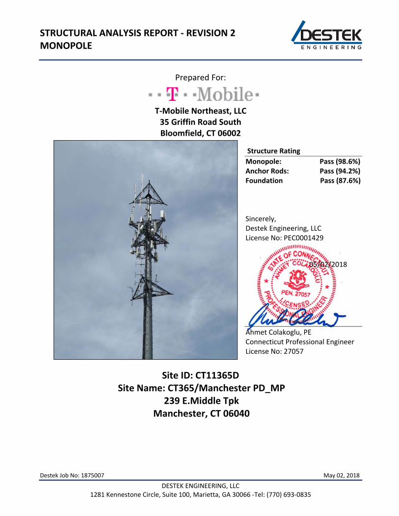
STRUCTURAL ANALYSIS REPORT ‐ REVISION 2 MONOPOLE
Prepared For:
T‐Mobile Northeast, LLC 35 Griffin Road South Bloomfield, CT 06002
Structure Rating
Monopole: Pass (98.6%) Anchor Rods: Pass (94.2%) Foundation Pass (87.6%)
Sincerely, Destek Engineering, LLC License No: PEC0001429 05/02/2018
Ahmet Colakoglu, PE Connecticut Professional Engineer License No: 27057
Site ID: CT11365D
Site Name: CT365/Manchester PD_MP 239 E.Middle Tpk
Manchester, CT 06040
Destek Job No: 1875007 May 02, 2018
CT11365D ‐ Structural Analysis Report – Rev. 2
P a g e | 0 DESTEK ENGINEERING, LLC 1281 Kennestone Circle, Suite 100, Marietta, GA 30066 ‐Tel: (770) 693‐0835
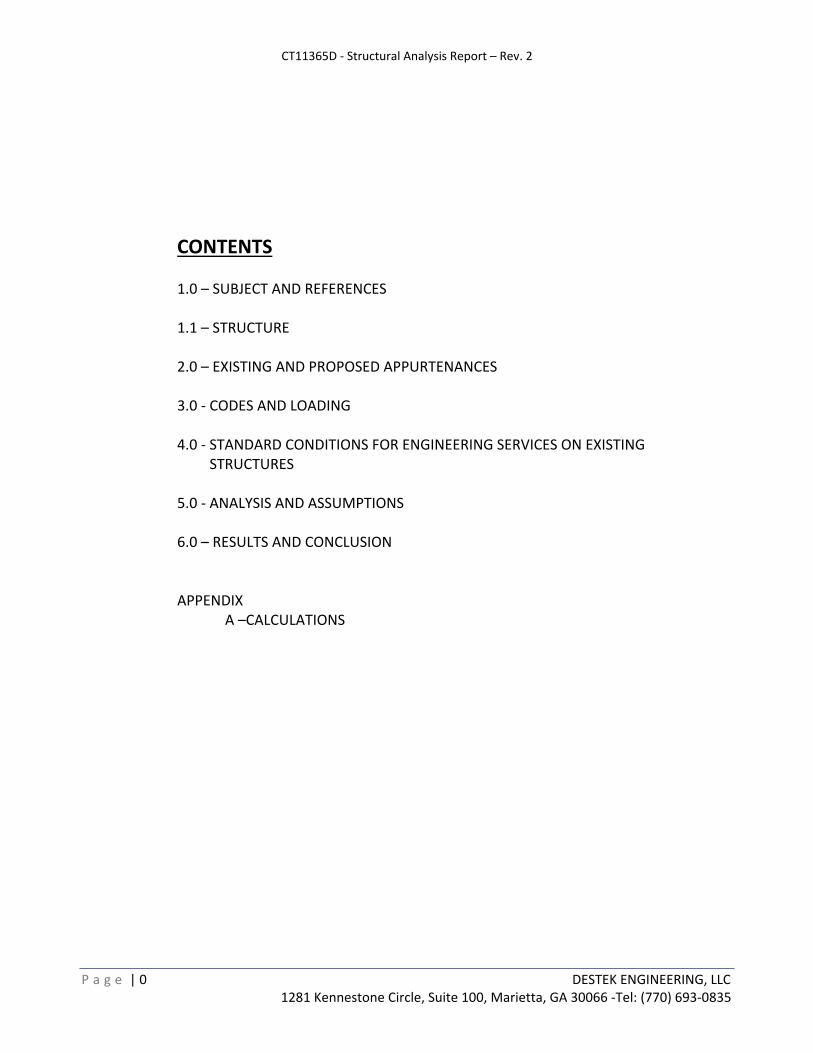
CONTENTS
1.0 – SUBJECT AND REFERENCES 1.1 – STRUCTURE
2.0 – EXISTING AND PROPOSED APPURTENANCES
3.0 ‐ CODES AND LOADING 4.0 ‐ STANDARD CONDITIONS FOR ENGINEERING SERVICES ON EXISTING STRUCTURES 5.0 ‐ ANALYSIS AND ASSUMPTIONS 6.0 – RESULTS AND CONCLUSION APPENDIX
A –CALCULATIONS
CT11365D ‐ Structural Analysis Report – Rev. 2
P a g e | 1 DESTEK ENGINEERING, LLC 1281 Kennestone Circle, Suite 100, Marietta, GA 30066 ‐Tel: (770) 693‐0835
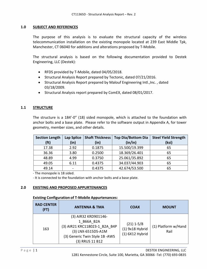
1.0 SUBJECT AND REFERENCES The purpose of this analysis is to evaluate the structural capacity of the wireless telecommunication installation on the existing monopole located at 239 East Middle Tpk, Manchester, CT 06040 for additions and alterations proposed by T‐Mobile. The structural analysis is based on the following documentation provided to Destek Engineering, LLC (Destek):
RFDS provided by T‐Mobile, dated 04/05/2018.
Structural Analysis Report prepared by Tectonic, dated 07/21/2016.
Structural Analysis Report prepared by Malouf Engineering Intl.,Inc. , dated 03/18/2009.
Structural Analysis report prepared by ComEX, dated 08/01/2017.
1.1 STRUCTURE
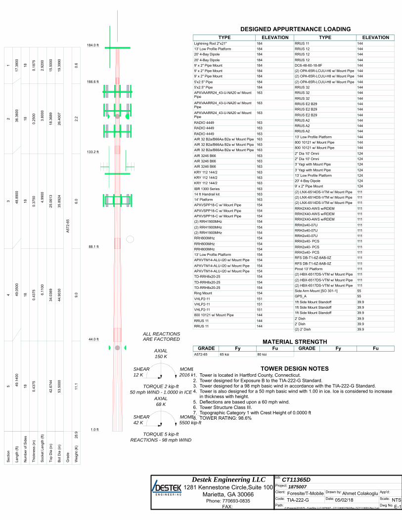
The structure is a 184’‐0” (18) sided monopole, which is attached to the foundation with anchor bolts and a base plate. Please refer to the software output in Appendix A, for tower geometry, member sizes, and other details.
Section Length (ft)
Lap Splice (in)
Shaft Thickness(in)
Top Dia/Bottom Dia (in/in)
Steel Yield Strength(ksi)
17.38 2.92 0.1875 15.500/19.399 65
36.36 3.80 0.2500 18.369/26.401 65
48.89 4.99 0.3750 25.061/35.892 65
49.05 6.11 0.4375 34.037/44.903 65
49.14 ‐ 0.4375 42.674/53.500 65 ‐ The monopole is 18 sided. ‐ It is connected to the foundation with anchor bolts and a base plate.
2.0 EXISTING AND PROPOSED APPURTENANCES
Existing Configuration of T‐Mobile Appurtenances:
RAD CENTER (FT)
ANTENNA & TMA COAX MOUNT
163
(3) AIR32 KRD901146‐1_B66A_B2A
(3) AIR21 KRC118023‐1_B2A_B4P (3) LNX‐6515DS‐A1M
(3) Generic Twin Style 1B ‐AWS (3) RRUS 11 B12
(21) 1‐5/8 (1) 9x18 Hybrid (1) 6X12 Hybrid
(1) Platform w/Hand Rail
CT11365D ‐ Structural Analysis Report – Rev. 2
P a g e | 2 DESTEK ENGINEERING, LLC 1281 Kennestone Circle, Suite 100, Marietta, GA 30066 ‐Tel: (770) 693‐0835
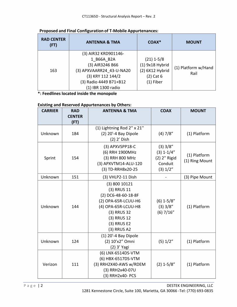
Proposed and Final Configuration of T‐Mobile Appurtenances:
RAD CENTER (FT)
ANTENNA & TMA COAX* MOUNT
163
(3) AIR32 KRD901146‐1_B66A_B2A
(3) AIR3246 B66 (3) APXVAARR24_43‐U‐NA20
(3) KRY 112 144/2 (3) Radio 4449 B71+B12
(1) IBR 1300 radio
(21) 1‐5/8 (1) 9x18 Hybrid (2) 6X12 Hybrid
(2) Cat 6 (1) Fiber
(1) Platform w/Hand Rail
*: Feedlines located inside the monopole
Existing and Reserved Appurtenances by Others:
CARRIER
RAD CENTER (FT)
ANTENNA & TMA COAX MOUNT
Unknown 184 (1) Lightning Rod 2'' x 21''
(2) 20'‐4 Bay Dipole (2) 2’ Dish
(4) 7/8” (1) Platform
Sprint 154
(3) APXVSPP18‐C (6) RRH 1900MHz (3) RRH 800 MHz
(3) APXVTM14‐ALU‐120 (3) TD‐RRH8x20‐25
(3) 3/8” (3) 1‐1/4” (2) 2'' Rigid Conduit (3) 1/2”
(1) Platform (1) Ring Mount
Unknown 151 (3) VHLP2‐11 Dish ‐ (3) Pipe Mount
Unknown 144
(3) 800 10121 (3) RRUS 11
(2) DC6‐48‐60‐18‐8F (2) OPA‐65R‐LCUU‐H6 (4) OPA‐65R‐LCUU‐H8
(3) RRUS 32 (3) RRUS 12 (3) RRUS E2 (3) RRUS A2
(6) 1‐5/8” (3) 3/8” (6) 7/16”
(1) Platform
Unknown 124 (1) 20'‐4 Bay Dipole (2) 10’x2” Omni
(2) 3’ Yagi (5) 1/2” (1) Platform
Verizon 111
(6) LNX‐6514DS‐VTM (6) HBX‐6517DS‐VTM
(3) RRH2X40‐AWS w/RDEM (3) RRH2x40‐07U (3) RRH2x40‐ PCS
(2) 1‐5/8” (1) Platform
CT11365D ‐ Structural Analysis Report – Rev. 2
P a g e | 3 DESTEK ENGINEERING, LLC 1281 Kennestone Circle, Suite 100, Marietta, GA 30066 ‐Tel: (770) 693‐0835
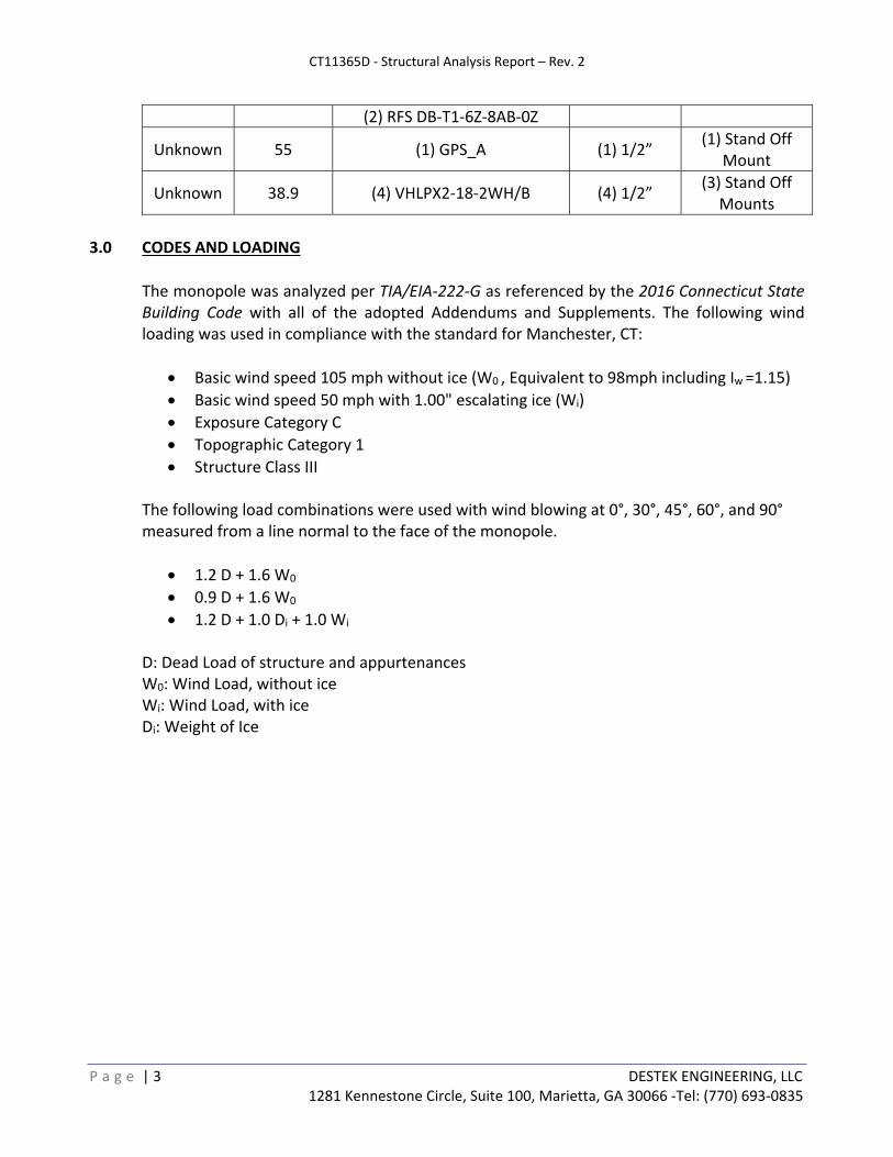
(2) RFS DB‐T1‐6Z‐8AB‐0Z
Unknown 55 (1) GPS_A (1) 1/2” (1) Stand Off
Mount
Unknown 38.9 (4) VHLPX2‐18‐2WH/B (4) 1/2” (3) Stand Off
Mounts
3.0 CODES AND LOADING
The monopole was analyzed per TIA/EIA‐222‐G as referenced by the 2016 Connecticut State Building Code with all of the adopted Addendums and Supplements. The following wind loading was used in compliance with the standard for Manchester, CT:
Basic wind speed 105 mph without ice (W0 , Equivalent to 98mph including Iw =1.15)
Basic wind speed 50 mph with 1.00" escalating ice (Wi)
Exposure Category C
Topographic Category 1
Structure Class III The following load combinations were used with wind blowing at 0°, 30°, 45°, 60°, and 90° measured from a line normal to the face of the monopole.
1.2 D + 1.6 W0
0.9 D + 1.6 W0
1.2 D + 1.0 Di + 1.0 Wi D: Dead Load of structure and appurtenances W0: Wind Load, without ice Wi: Wind Load, with ice Di: Weight of Ice
CT11365D ‐ Structural Analysis Report – Rev. 2
P a g e | 4 DESTEK ENGINEERING, LLC 1281 Kennestone Circle, Suite 100, Marietta, GA 30066 ‐Tel: (770) 693‐0835
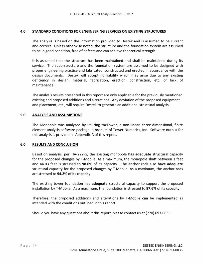
4.0 STANDARD CONDITIONS FOR ENGINEERING SERVICES ON EXISTING STRUCTURES
The analysis is based on the information provided to Destek and is assumed to be current and correct. Unless otherwise noted, the structure and the foundation system are assumed to be in good condition, free of defects and can achieve theoretical strength. It is assumed that the structure has been maintained and shall be maintained during its service. The superstructure and the foundation system are assumed to be designed with proper engineering practice and fabricated, constructed and erected in accordance with the design documents. Destek will accept no liability which may arise due to any existing deficiency in design, material, fabrication, erection, construction, etc. or lack of maintenance.
The analysis results presented in this report are only applicable for the previously mentioned existing and proposed additions and alterations. Any deviation of the proposed equipment and placement, etc., will require Destek to generate an additional structural analysis.
5.0 ANALYSIS AND ASSUMPTIONS
The Monopole was analyzed by utilizing tnxTower, a non‐linear, three‐dimensional, finite element‐analysis software package, a product of Tower Numerics, Inc. Software output for this analysis is provided in Appendix A of this report.
6.0 RESULTS AND CONCLUSION
Based on analysis, per TIA‐222‐G, the existing monopole has adequate structural capacity for the proposed changes by T‐Mobile. As a maximum, the monopole shaft between 1 feet and 44.03 feet is stressed to 98.6% of its capacity. The anchor rods also have adequate structural capacity for the proposed changes by T‐Mobile. As a maximum, the anchor rods are stressed to 94.2% of its capacity. The existing tower foundation has adequate structural capacity to support the proposed installation by T‐Mobile. As a maximum, the foundation is stressed to 87.6% of its capacity.
Therefore, the proposed additions and alterations by T‐Mobile can be implemented as intended with the conditions outlined in this report.
Should you have any questions about this report, please contact us at (770) 693‐0835.

APPENDIX A CALCULATIONS
Destek Engineering LLC 1281 Kennestone Circle,Suite 100
Marietta, GA 30066 Phone: 770693-0835
FAX:
Job: CT11365D Project: 1875007 Client: Foresite/T-Mobile Drawn by: Ahmet Colakoglu App'd:
Code: TIA-222-G Date: 05/02/18 Scale: NTS Path:
Z:\Projects\2018\75 - ForeSite LLC\1875007 - CT11365D\TNX\Rev.2\CT11365D-Rev.2.eri Dwg No. E-1
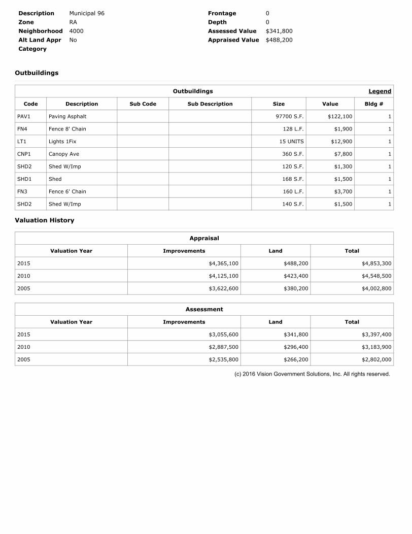
184.0 ft
166.6 ft
133.2 ft
88.1 ft
44.0 ft
1.0 ft
REACTIONS - 98 mph WINDTORQUE 5 kip-ft
42 KSHEAR
5500 kip-ftMOMENT
68 KAXIAL
50 mph WIND - 1.0000 in ICETORQUE 2 kip-ft
12 KSHEAR
2016 kip-ftMOMENT
150 KAXIAL
ARE FACTOREDALL REACTIONS
S
ect
ion
12
34
5
Le
ngth
(ft
)1
7.3
80
03
6.3
60
04
8.8
90
04
9.0
50
04
9.1
40
0
N
um
be
r o
f S
ide
s1
81
81
81
81
8
T
hic
kne
ss (
in)
0.1
87
50
.25
00
0.3
75
00
.43
75
0.4
37
5
S
ock
et
Le
ng
th (
ft)
2.9
20
03
.80
00
4.9
90
06
.11
00
T
op
Dia
(in
)1
5.5
00
01
8.3
68
92
5.0
61
33
4.0
36
94
2.6
74
4
B
ot
Dia
(in
)1
9.3
99
02
6.4
00
73
5.8
92
44
4.9
03
05
3.5
00
0
G
rad
eA
57
2-6
5
W
eig
ht
(K)
0.6
2.2
6.0
9.0
11
.12
8.9
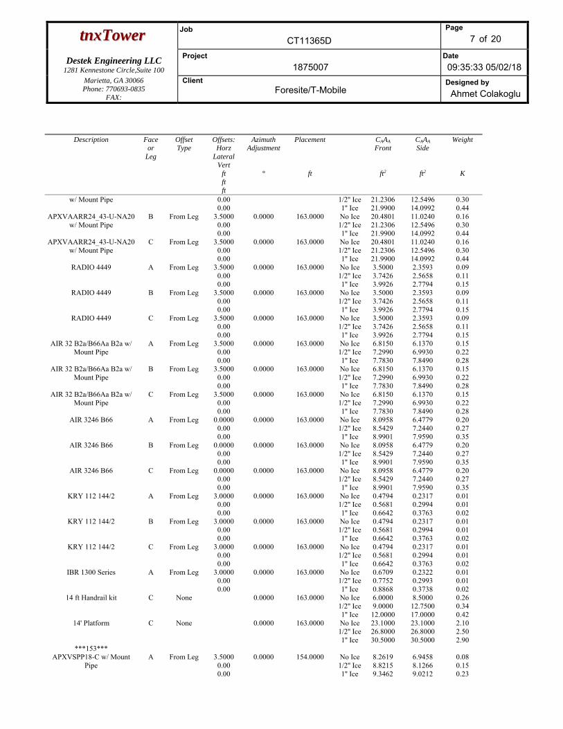
Lightning Rod 2"x21" 184 13' Low Profile Platform 184 20' 4-Bay Dipole 184 20' 4-Bay Dipole 184 9' x 2" Pipe Mount 184 9' x 2" Pipe Mount 184 9' x 2" Pipe Mount 184 5'x2.5" Pipe 184 5'x2.5" Pipe 184 APXVAARR24_43-U-NA20 w/ Mount Pipe
163 APXVAARR24_43-U-NA20 w/ Mount Pipe
163 APXVAARR24_43-U-NA20 w/ Mount Pipe
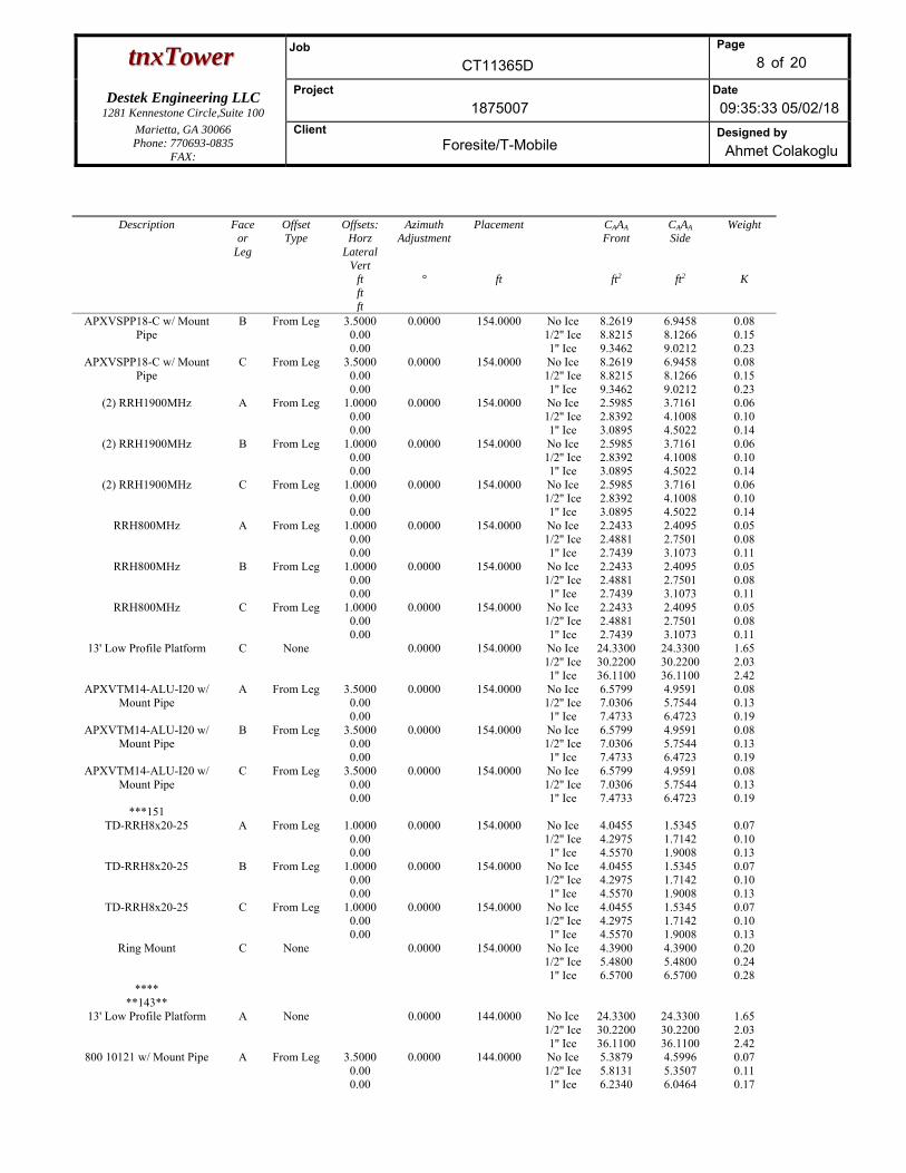
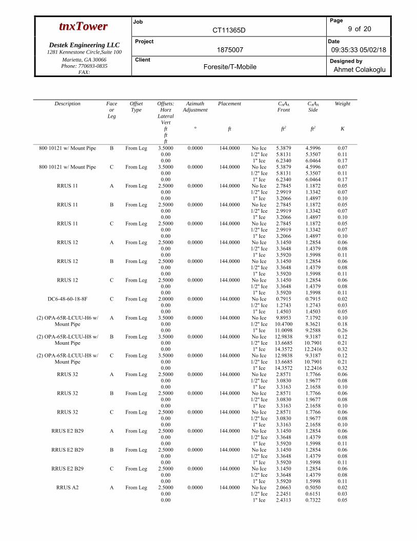
163 RADIO 4449 163 RADIO 4449 163 RADIO 4449 163 AIR 32 B2a/B66Aa B2a w/ Mount Pipe 163 AIR 32 B2a/B66Aa B2a w/ Mount Pipe 163 AIR 32 B2a/B66Aa B2a w/ Mount Pipe 163 AIR 3246 B66 163 AIR 3246 B66 163 AIR 3246 B66 163 KRY 112 144/2 163 KRY 112 144/2 163 KRY 112 144/2 163 IBR 1300 Series 163 14 ft Handrail kit 163 14' Platform 163 APXVSPP18-C w/ Mount Pipe 154 APXVSPP18-C w/ Mount Pipe 154 APXVSPP18-C w/ Mount Pipe 154 (2) RRH1900MHz 154 (2) RRH1900MHz 154 (2) RRH1900MHz 154 RRH800MHz 154 RRH800MHz 154 RRH800MHz 154 13' Low Profile Platform 154 APXVTM14-ALU-I20 w/ Mount Pipe 154 APXVTM14-ALU-I20 w/ Mount Pipe 154 APXVTM14-ALU-I20 w/ Mount Pipe 154 TD-RRH8x20-25 154 TD-RRH8x20-25 154 TD-RRH8x20-25 154 Ring Mount 154 VHLP2-11 151 VHLP2-11 151 VHLP2-11 151 800 10121 w/ Mount Pipe 144 RRUS 11 144 RRUS 11 144 RRUS 11 144 RRUS 12 144 RRUS 12 144 RRUS 12 144 DC6-48-60-18-8F 144 (2) OPA-65R-LCUU-H6 w/ Mount Pipe 144 (2) OPA-65R-LCUU-H8 w/ Mount Pipe 144 (2) OPA-65R-LCUU-H8 w/ Mount Pipe 144 RRUS 32 144 RRUS 32 144 RRUS 32 144 RRUS E2 B29 144 RRUS E2 B29 144 RRUS E2 B29 144 RRUS A2 144 RRUS A2 144 RRUS A2 144 13' Low Profile Platform 144 800 10121 w/ Mount Pipe 144 800 10121 w/ Mount Pipe 144 2" Dia 10' Omni 124 2" Dia 10' Omni 124 3' Yagi with Mount Pipe 124 3' Yagi with Mount Pipe 124 13' Low Profile Platform 124 20' 4-Bay Dipole 124 9' x 2" Pipe Mount 124 (2) LNX-6514DS-VTM w/ Mount Pipe 111 (2) LNX-6514DS-VTM w/ Mount Pipe 111 (2) LNX-6514DS-VTM w/ Mount Pipe 111 RRH2X40-AWS w/RDEM 111 RRH2X40-AWS w/RDEM 111 RRH2X40-AWS w/RDEM 111 RRH2x40-07U 111 RRH2x40-07U 111 RRH2x40-07U 111 RRH2x40- PCS 111 RRH2x40- PCS 111 RRH2x40- PCS 111 RFS DB-T1-6Z-8AB-0Z 111 RFS DB-T1-6Z-8AB-0Z 111 Pirod 13' Platform 111 (2) HBX-6517DS-VTM w/ Mount Pipe 111 (2) HBX-6517DS-VTM w/ Mount Pipe 111 (2) HBX-6517DS-VTM w/ Mount Pipe 111 Side Arm Mount [SO 301-1] 55 GPS_A 55 1ft Side Mount Standoff 39.9 1ft Side Mount Standoff 39.9 1ft Side Mount Standoff 39.9 2' Dish 39.9 2' Dish 39.9 (2) 2' Dish 39.9DESIGNED APPURTENANCE LOADINGTYPE TYPEELEVATION ELEVATION
Lightning Rod 2"x21" 184
13' Low Profile Platform 184
20' 4-Bay Dipole 184
20' 4-Bay Dipole 184
9' x 2" Pipe Mount 184
9' x 2" Pipe Mount 184
9' x 2" Pipe Mount 184
5'x2.5" Pipe 184
5'x2.5" Pipe 184
APXVAARR24_43-U-NA20 w/ Mount Pipe
163
APXVAARR24_43-U-NA20 w/ Mount Pipe
163
APXVAARR24_43-U-NA20 w/ Mount Pipe
163
RADIO 4449 163
RADIO 4449 163
RADIO 4449 163
AIR 32 B2a/B66Aa B2a w/ Mount Pipe 163
AIR 32 B2a/B66Aa B2a w/ Mount Pipe 163
AIR 32 B2a/B66Aa B2a w/ Mount Pipe 163
AIR 3246 B66 163
AIR 3246 B66 163
AIR 3246 B66 163
KRY 112 144/2 163
KRY 112 144/2 163
KRY 112 144/2 163
IBR 1300 Series 163
14 ft Handrail kit 163
14' Platform 163
APXVSPP18-C w/ Mount Pipe 154
APXVSPP18-C w/ Mount Pipe 154
APXVSPP18-C w/ Mount Pipe 154
(2) RRH1900MHz 154
(2) RRH1900MHz 154
(2) RRH1900MHz 154
RRH800MHz 154
RRH800MHz 154
RRH800MHz 154
13' Low Profile Platform 154
APXVTM14-ALU-I20 w/ Mount Pipe 154
APXVTM14-ALU-I20 w/ Mount Pipe 154
APXVTM14-ALU-I20 w/ Mount Pipe 154
TD-RRH8x20-25 154
TD-RRH8x20-25 154
TD-RRH8x20-25 154
Ring Mount 154
VHLP2-11 151
VHLP2-11 151
VHLP2-11 151
800 10121 w/ Mount Pipe 144
RRUS 11 144
RRUS 11 144
RRUS 11 144
RRUS 12 144
RRUS 12 144
RRUS 12 144
DC6-48-60-18-8F 144
(2) OPA-65R-LCUU-H6 w/ Mount Pipe 144
(2) OPA-65R-LCUU-H8 w/ Mount Pipe 144
(2) OPA-65R-LCUU-H8 w/ Mount Pipe 144
RRUS 32 144
RRUS 32 144
RRUS 32 144
RRUS E2 B29 144
RRUS E2 B29 144
RRUS E2 B29 144
RRUS A2 144
RRUS A2 144
RRUS A2 144
13' Low Profile Platform 144
800 10121 w/ Mount Pipe 144
800 10121 w/ Mount Pipe 144
2" Dia 10' Omni 124
2" Dia 10' Omni 124
3' Yagi with Mount Pipe 124
3' Yagi with Mount Pipe 124
13' Low Profile Platform 124
20' 4-Bay Dipole 124
9' x 2" Pipe Mount 124
(2) LNX-6514DS-VTM w/ Mount Pipe 111
(2) LNX-6514DS-VTM w/ Mount Pipe 111
(2) LNX-6514DS-VTM w/ Mount Pipe 111
RRH2X40-AWS w/RDEM 111
RRH2X40-AWS w/RDEM 111
RRH2X40-AWS w/RDEM 111
RRH2x40-07U 111
RRH2x40-07U 111
RRH2x40-07U 111
RRH2x40- PCS 111
RRH2x40- PCS 111
RRH2x40- PCS 111
RFS DB-T1-6Z-8AB-0Z 111
RFS DB-T1-6Z-8AB-0Z 111
Pirod 13' Platform 111
(2) HBX-6517DS-VTM w/ Mount Pipe 111
(2) HBX-6517DS-VTM w/ Mount Pipe 111
(2) HBX-6517DS-VTM w/ Mount Pipe 111
Side Arm Mount [SO 301-1] 55
GPS_A 55
1ft Side Mount Standoff 39.9
1ft Side Mount Standoff 39.9
1ft Side Mount Standoff 39.9
2' Dish 39.9
2' Dish 39.9
(2) 2' Dish 39.9
MATERIAL STRENGTHGRADE GRADEFy FyFu Fu
A572-65 65 ksi 80 ksi
TOWER DESIGN NOTES1. Tower is located in Hartford County, Connecticut.2. Tower designed for Exposure B to the TIA-222-G Standard.3. Tower designed for a 98 mph basic wind in accordance with the TIA-222-G Standard.4. Tower is also designed for a 50 mph basic wind with 1.00 in ice. Ice is considered to increase
in thickness with height.5. Deflections are based upon a 60 mph wind.6. Tower Structure Class III.7. Topographic Category 1 with Crest Height of 0.0000 ft8. TOWER RATING: 98.6%
ttnnxxTToowweerr Job
CT11365D
Page
1 of 20
Destek Engineering LLC 1281 Kennestone Circle,Suite 100
Project
1875007 Date
09:35:33 05/02/18 Marietta, GA 30066 Phone: 770693-0835
FAX:
Client Foresite/T-Mobile
Designed by
Ahmet Colakoglu
Tower Input Data
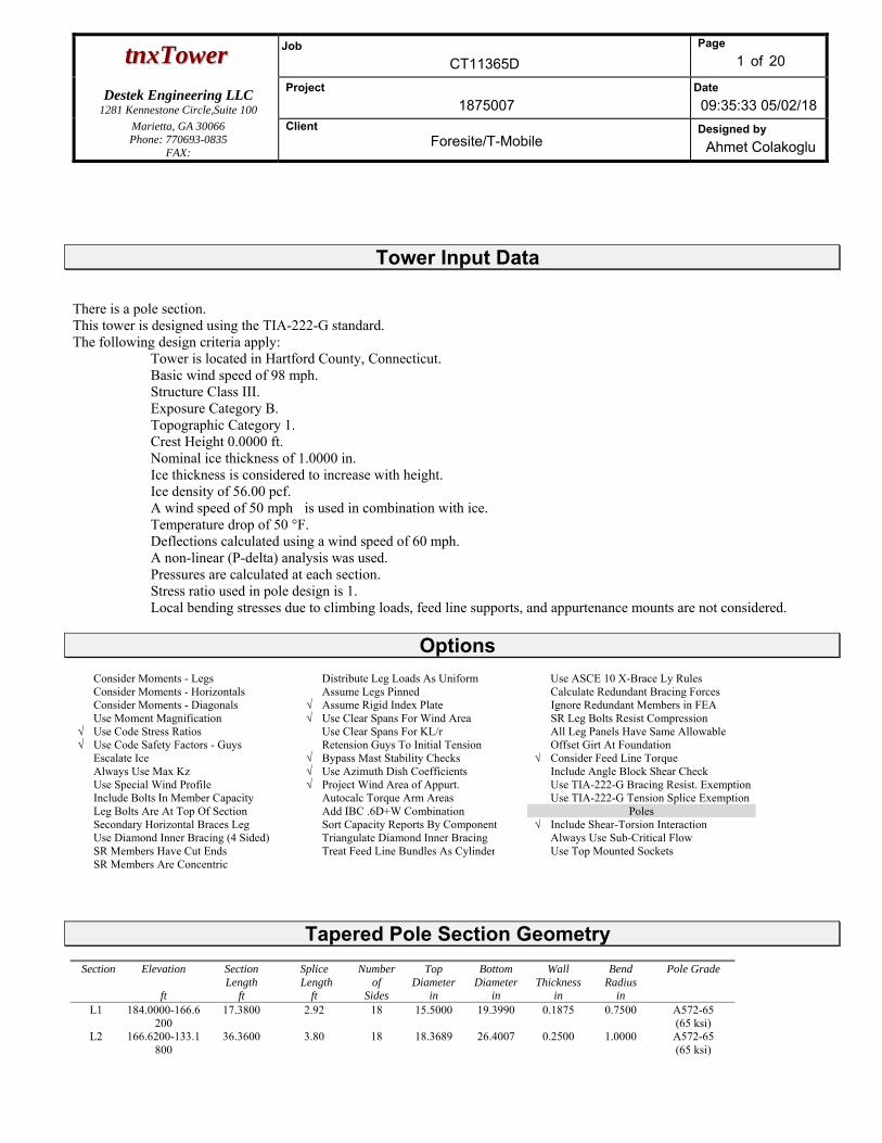
There is a pole section. This tower is designed using the TIA-222-G standard. The following design criteria apply:
Tower is located in Hartford County, Connecticut. Basic wind speed of 98 mph. Structure Class III. Exposure Category B. Topographic Category 1. Crest Height 0.0000 ft. Nominal ice thickness of 1.0000 in. Ice thickness is considered to increase with height. Ice density of 56.00 pcf. A wind speed of 50 mph is used in combination with ice. Temperature drop of 50 °F. Deflections calculated using a wind speed of 60 mph. A non-linear (P-delta) analysis was used. Pressures are calculated at each section. Stress ratio used in pole design is 1. Local bending stresses due to climbing loads, feed line supports, and appurtenance mounts are not considered.
Options
Consider Moments - Legs Distribute Leg Loads As Uniform Use ASCE 10 X-Brace Ly Rules Consider Moments - Horizontals Assume Legs Pinned Calculate Redundant Bracing Forces Consider Moments - Diagonals √ Assume Rigid Index Plate Ignore Redundant Members in FEA Use Moment Magnification √ Use Clear Spans For Wind Area SR Leg Bolts Resist Compression
√ Use Code Stress Ratios Use Clear Spans For KL/r All Leg Panels Have Same Allowable√ Use Code Safety Factors - Guys Retension Guys To Initial Tension Offset Girt At Foundation Escalate Ice √ Bypass Mast Stability Checks √ Consider Feed Line Torque Always Use Max Kz √ Use Azimuth Dish Coefficients Include Angle Block Shear Check Use Special Wind Profile √ Project Wind Area of Appurt. Use TIA-222-G Bracing Resist. Exemption Include Bolts In Member Capacity Autocalc Torque Arm Areas Use TIA-222-G Tension Splice Exemption Leg Bolts Are At Top Of Section Add IBC .6D+W Combination Poles Secondary Horizontal Braces Leg Sort Capacity Reports By Component √ Include Shear-Torsion Interaction Use Diamond Inner Bracing (4 Sided) Triangulate Diamond Inner Bracing Always Use Sub-Critical Flow SR Members Have Cut Ends Treat Feed Line Bundles As Cylinder Use Top Mounted Sockets SR Members Are Concentric
Tapered Pole Section Geometry Section Elevation
ft
Section Length
ft
Splice Length
ft
Numberof
Sides
Top Diameter
in
Bottom Diameter
in
Wall Thickness
in
Bend Radius
in
Pole Grade
L1 184.0000-166.6200
17.3800 2.92 18 15.5000 19.3990 0.1875 0.7500 A572-65 (65 ksi)
L2 166.6200-133.1800
36.3600 3.80 18 18.3689 26.4007 0.2500 1.0000 A572-65 (65 ksi)
ttnnxxTToowweerr Job
CT11365D
Page
2 of 20
Destek Engineering LLC 1281 Kennestone Circle,Suite 100
Project
1875007 Date
09:35:33 05/02/18 Marietta, GA 30066 Phone: 770693-0835
FAX:
Client Foresite/T-Mobile
Designed by
Ahmet Colakoglu
Section Elevation
ft
Section Length
ft
Splice Length
ft
Numberof
Sides
Top Diameter
in
Bottom Diameter
in
Wall Thickness
in
Bend Radius
in
Pole Grade
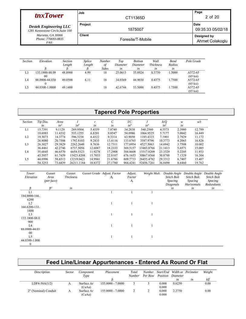
L3 133.1800-88.0900
48.8900 4.99 18 25.0613 35.8924 0.3750 1.5000 A572-65 (65 ksi)
L4 88.0900-44.0300
49.0500 6.11 18 34.0369 44.9030 0.4375 1.7500 A572-65 (65 ksi)
L5 44.0300-1.0000 49.1400 18 42.6744 53.5000 0.4375 1.7500 A572-65 (65 ksi)
Tapered Pole Properties Section Tip Dia.
in Area in2
I in4
r in
C in
I/C in3
J in4
It/Q in2
w in
w/t
L1 15.7391 9.1129 269.9504 5.4359 7.8740 34.2838 540.2560 4.5573 2.3980 12.789 19.6983 11.4332 533.1255 6.8201 9.8547 54.0986 1066.9525 5.7177 3.0842 16.449
L2 19.3073 14.3774 596.3238 6.4322 9.3314 63.9050 1193.4323 7.1901 2.7929 11.172 26.8080 20.7506 1792.8103 9.2835 13.4116 133.6765 3587.9796 10.3773 4.2065 16.826
L3 26.3027 29.3829 2262.2648 8.7636 12.7311 177.6954 4527.5063 14.6942 3.7508 10.002 36.4461 42.2746 6737.5056 12.6087 18.2333 369.5157 13483.8766 21.1413 5.6571 15.085
L4 35.6845 46.6570 6654.5323 11.9278 17.2908 384.8608 13317.8209 23.3329 5.2205 11.933 45.5957 61.7459 15423.8208 15.7853 22.8107 676.1653 30867.9366 30.8788 7.1329 16.304
L5 44.6996 58.6513 13219.0421 14.9941 21.6786 609.7733 26455.4782 29.3312 6.7407 15.407 54.3253 73.6839 26211.1184 18.8372 27.1780 964.4241 52456.7261 36.8490 8.6460 19.762
Tower
Elevation
ft
Gusset Area
(per face)
ft2
Gusset Thickness
in
Gusset Grade Adjust. FactorAf
Adjust. Factor
Ar
Weight Mult.
Double Angle Stitch Bolt Spacing
Diagonals in
Double Angle Stitch Bolt Spacing
Horizontals in
Double Angle Stitch Bolt Spacing
Redundants in
L1 184.0000-166.
6200
1 1 1
L2 166.6200-133.
1800
1 1 1
L3 133.1800-88.0
900
1 1 1
L4 88.0900-44.03
00
1 1 1
L5 44.0300-1.000
0
1 1 1
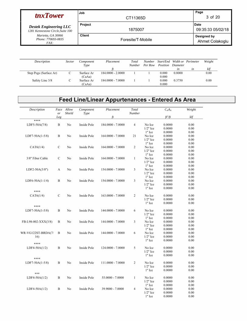
Feed Line/Linear Appurtenances - Entered As Round Or Flat
Description Sector Component Type
Placement
ft
Total Number
Number Per Row
Start/EndPosition
Width or Diameter
in
Perimeter
in
Weight
klfLDF4-50A(1/2) A Surface Ar
(CaAa) 155.0000 - 7.0000 3 3 0.000
0.0000.6250 0.00
2'' (Nominal) Conduit A Surface Ar (CaAa)
155.0000 - 7.0000 2 2 0.000 0.000
2.3750 0.00
ttnnxxTToowweerr Job
CT11365D
Page
3 of 20
Destek Engineering LLC 1281 Kennestone Circle,Suite 100
Project
1875007 Date
09:35:33 05/02/18 Marietta, GA 30066 Phone: 770693-0835
FAX:
Client Foresite/T-Mobile
Designed by
Ahmet Colakoglu
Description Sector Component Type
Placement
ft
Total Number
Number Per Row
Start/EndPosition
Width or Diameter
in
Perimeter
in
Weight
klfStep Pegs (Surface Ar) C Surface Ar
(CaAa) 184.0000 - 2.0000 1 1 0.000
0.0000.8000 0.00
Safety Line 3/8 C Surface Ar (CaAa)
184.0000 - 7.0000 1 1 0.000 0.000
0.3750 0.00
Feed Line/Linear Appurtenances - Entered As Area
Description Face or
Leg
Allow Shield
Component Type
Placement
ft
Total Number
CAAA
ft2/ft
Weight
klf ****
LDF5-50A(7/8) B No Inside Pole 184.0000 - 7.0000 4 No Ice 1/2'' Ice 1'' Ice
0.0000 0.0000 0.0000
0.00 0.00 0.00
LDF7-50A(1-5/8) B No Inside Pole 164.0000 - 7.0000 21 No Ice 1/2'' Ice 1'' Ice
0.0000 0.0000 0.0000
0.00 0.00 0.00
CAT6(1/4) C No Inside Pole 164.0000 - 7.0000 2 No Ice 1/2'' Ice 1'' Ice
0.0000 0.0000 0.0000
0.00 0.00 0.00
3/8'' Fiber Cable C No Inside Pole 164.0000 - 7.0000 1 No Ice 1/2'' Ice 1'' Ice
0.0000 0.0000 0.0000
0.00 0.00 0.00
LDF2-50A(3/8'') A No Inside Pole 154.0000 - 7.0000 3 No Ice 1/2'' Ice 1'' Ice
0.0000 0.0000 0.0000
0.00 0.00 0.00
LDF6-50A(1-1/4) B No Inside Pole 154.0000 - 7.0000 3 No Ice 1/2'' Ice 1'' Ice
0.0000 0.0000 0.0000
0.00 0.00 0.00
**** CAT6(1/4) C No Inside Pole 163.0000 - 7.0000 2 No Ice
1/2'' Ice 1'' Ice
0.0000 0.0000 0.0000
0.00 0.00 0.00
**** LDF7-50A(1-5/8) B No Inside Pole 144.0000 - 7.0000 6 No Ice
1/2'' Ice 1'' Ice
0.0000 0.0000 0.0000
0.00 0.00 0.00
FB-L98-002-XXX(3/8) B No Inside Pole 144.0000 - 7.0000 3 No Ice 1/2'' Ice 1'' Ice
0.0000 0.0000 0.0000
0.00 0.00 0.00
WR-VG122ST-BRDA(7/16)
B No Inside Pole 144.0000 - 7.0000 6 No Ice 1/2'' Ice 1'' Ice
0.0000 0.0000 0.0000
0.00 0.00 0.00
**** LDF4-50A(1/2) B No Inside Pole 124.0000 - 7.0000 5 No Ice
1/2'' Ice 1'' Ice
0.0000 0.0000 0.0000
0.00 0.00 0.00
**** LDF7-50A(1-5/8) B No Inside Pole 111.0000 - 7.0000 2 No Ice
1/2'' Ice 1'' Ice
0.0000 0.0000 0.0000
0.00 0.00 0.00
*** LDF4-50A(1/2) B No Inside Pole 55.0000 - 7.0000 1 No Ice
1/2'' Ice 1'' Ice
0.0000 0.0000 0.0000
0.00 0.00 0.00
LDF4-50A(1/2) B No Inside Pole 39.9000 - 7.0000 4 No Ice 1/2'' Ice 1'' Ice
0.0000 0.0000 0.0000
0.00 0.00 0.00
ttnnxxTToowweerr Job
CT11365D
Page
4 of 20
Destek Engineering LLC 1281 Kennestone Circle,Suite 100
Project
1875007 Date
09:35:33 05/02/18 Marietta, GA 30066 Phone: 770693-0835
FAX:
Client Foresite/T-Mobile
Designed by
Ahmet Colakoglu
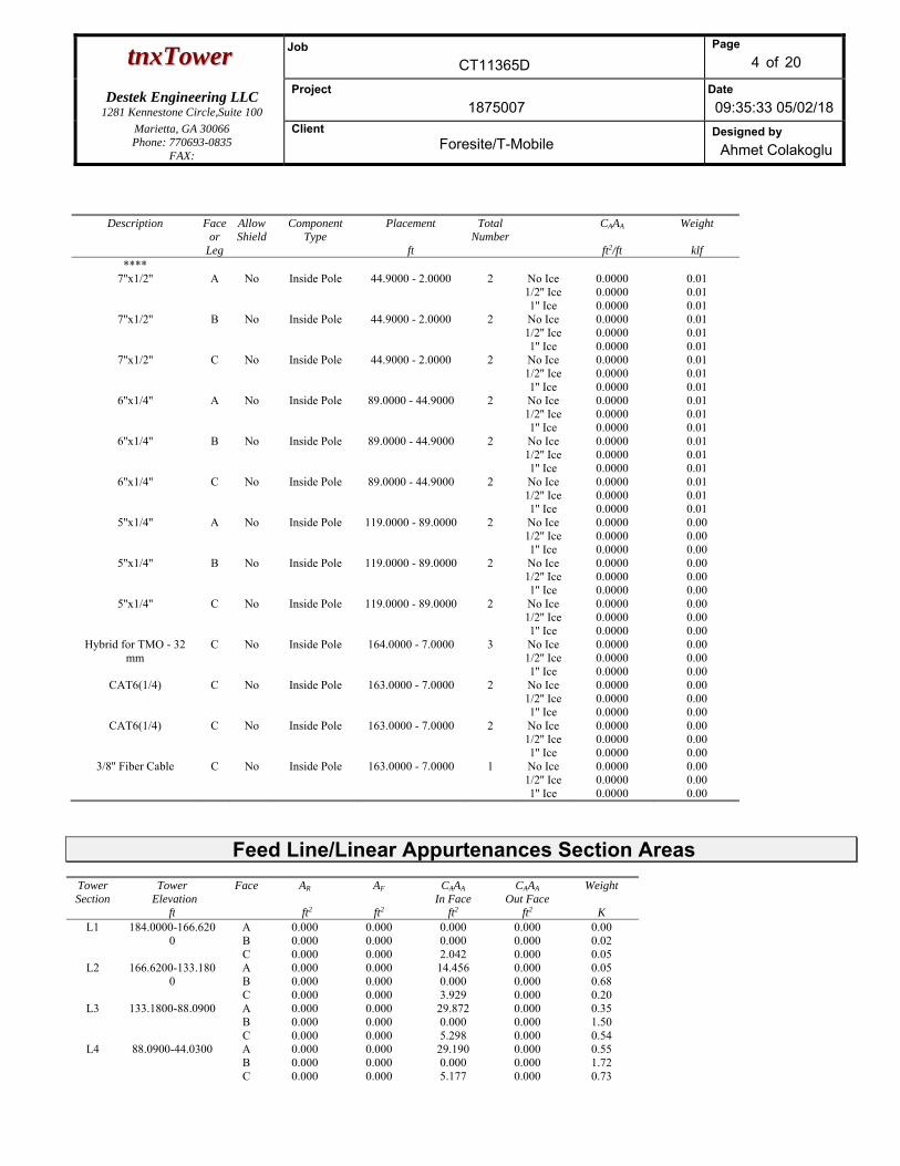
Description Face or
Leg
Allow Shield
Component Type
Placement
ft
Total Number
CAAA
ft2/ft
Weight
klf ****
7''x1/2'' A No Inside Pole 44.9000 - 2.0000 2 No Ice 1/2'' Ice 1'' Ice
0.0000 0.0000 0.0000
0.01 0.01 0.01
7''x1/2'' B No Inside Pole 44.9000 - 2.0000 2 No Ice 1/2'' Ice 1'' Ice
0.0000 0.0000 0.0000
0.01 0.01 0.01
7''x1/2'' C No Inside Pole 44.9000 - 2.0000 2 No Ice 1/2'' Ice 1'' Ice
0.0000 0.0000 0.0000
0.01 0.01 0.01
6''x1/4'' A No Inside Pole 89.0000 - 44.9000 2 No Ice 1/2'' Ice 1'' Ice
0.0000 0.0000 0.0000
0.01 0.01 0.01
6''x1/4'' B No Inside Pole 89.0000 - 44.9000 2 No Ice 1/2'' Ice 1'' Ice
0.0000 0.0000 0.0000
0.01 0.01 0.01
6''x1/4'' C No Inside Pole 89.0000 - 44.9000 2 No Ice 1/2'' Ice 1'' Ice
0.0000 0.0000 0.0000
0.01 0.01 0.01
5''x1/4'' A No Inside Pole 119.0000 - 89.0000 2 No Ice 1/2'' Ice 1'' Ice
0.0000 0.0000 0.0000
0.00 0.00 0.00
5''x1/4'' B No Inside Pole 119.0000 - 89.0000 2 No Ice 1/2'' Ice 1'' Ice
0.0000 0.0000 0.0000
0.00 0.00 0.00
5''x1/4'' C No Inside Pole 119.0000 - 89.0000 2 No Ice 1/2'' Ice 1'' Ice
0.0000 0.0000 0.0000
0.00 0.00 0.00
Hybrid for TMO - 32 mm
C No Inside Pole 164.0000 - 7.0000 3 No Ice 1/2'' Ice 1'' Ice
0.0000 0.0000 0.0000
0.00 0.00 0.00
CAT6(1/4) C No Inside Pole 163.0000 - 7.0000 2 No Ice 1/2'' Ice 1'' Ice
0.0000 0.0000 0.0000
0.00 0.00 0.00
CAT6(1/4) C No Inside Pole 163.0000 - 7.0000 2 No Ice 1/2'' Ice 1'' Ice
0.0000 0.0000 0.0000
0.00 0.00 0.00
3/8'' Fiber Cable C No Inside Pole 163.0000 - 7.0000 1 No Ice 1/2'' Ice 1'' Ice
0.0000 0.0000 0.0000
0.00 0.00 0.00
Feed Line/Linear Appurtenances Section Areas Tower Section
Tower Elevation
ft
Face AR
ft2
AF
ft2
CAAA
In Face ft2
CAAA
Out Face ft2
Weight
KL1 184.0000-166.620
0 A B C
0.000 0.000 0.000
0.000 0.000 0.000
0.000 0.000 2.042
0.000 0.000 0.000
0.00 0.02 0.05
L2 166.6200-133.1800
A B C
0.000 0.000 0.000
0.000 0.000 0.000
14.456 0.000 3.929
0.000 0.000 0.000
0.05 0.68 0.20
L3 133.1800-88.0900 A B C
0.000 0.000 0.000
0.000 0.000 0.000
29.872 0.000 5.298
0.000 0.000 0.000
0.35 1.50 0.54
L4 88.0900-44.0300 A B C
0.000 0.000 0.000
0.000 0.000 0.000
29.190 0.000 5.177
0.000 0.000 0.000
0.55 1.72 0.73
ttnnxxTToowweerr Job
CT11365D
Page
5 of 20
Destek Engineering LLC 1281 Kennestone Circle,Suite 100
Project
1875007 Date
09:35:33 05/02/18 Marietta, GA 30066 Phone: 770693-0835
FAX:
Client Foresite/T-Mobile
Designed by
Ahmet Colakoglu
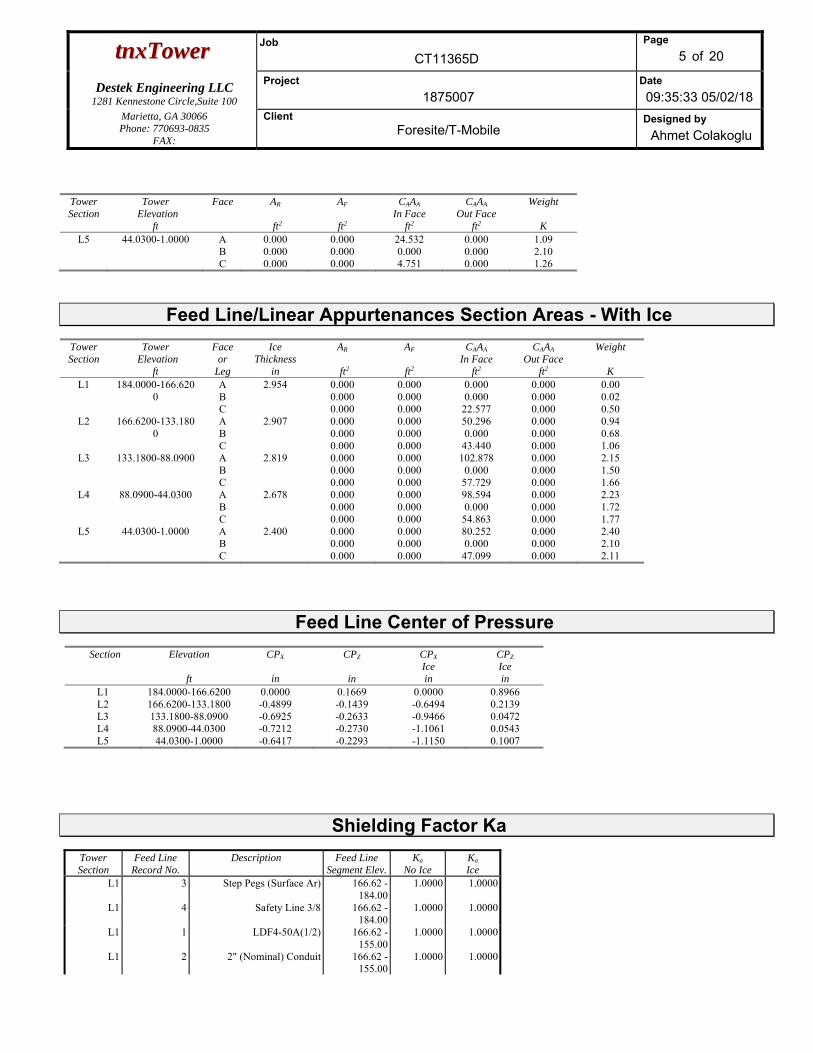
Tower Section
Tower Elevation
ft
Face AR
ft2
AF
ft2
CAAA
In Face ft2
CAAA
Out Face ft2
Weight
KL5 44.0300-1.0000 A
B C
0.000 0.000 0.000
0.000 0.000 0.000
24.532 0.000 4.751
0.000 0.000 0.000
1.09 2.10 1.26
Feed Line/Linear Appurtenances Section Areas - With Ice Tower Section
Tower Elevation
ft
Face or
Leg
Ice Thickness
in
AR
ft2
AF
ft2
CAAA
In Face ft2
CAAA
Out Face ft2
Weight
K L1 184.0000-166.620
0 A B C
2.954 0.000 0.000 0.000
0.000 0.000 0.000
0.000 0.000
22.577
0.000 0.000 0.000
0.00 0.02 0.50
L2 166.6200-133.1800
A B C
2.907 0.000 0.000 0.000
0.000 0.000 0.000
50.296 0.000
43.440
0.000 0.000 0.000
0.94 0.68 1.06
L3 133.1800-88.0900 A B C
2.819 0.000 0.000 0.000
0.000 0.000 0.000
102.878 0.000
57.729
0.000 0.000 0.000
2.15 1.50 1.66
L4 88.0900-44.0300 A B C
2.678 0.000 0.000 0.000
0.000 0.000 0.000
98.594 0.000
54.863
0.000 0.000 0.000
2.23 1.72 1.77
L5 44.0300-1.0000 A B C
2.400 0.000 0.000 0.000
0.000 0.000 0.000
80.252 0.000
47.099
0.000 0.000 0.000
2.40 2.10 2.11
Feed Line Center of Pressure
Section Elevation
ft
CPX
in
CPZ
in
CPX
Ice in
CPZ
Ice in
L1 184.0000-166.6200 0.0000 0.1669 0.0000 0.8966L2 166.6200-133.1800 -0.4899 -0.1439 -0.6494 0.2139L3 133.1800-88.0900 -0.6925 -0.2633 -0.9466 0.0472L4 88.0900-44.0300 -0.7212 -0.2730 -1.1061 0.0543L5 44.0300-1.0000 -0.6417 -0.2293 -1.1150 0.1007
Shielding Factor Ka
Tower Section
Feed Line Record No.
Description Feed Line Segment Elev.
Ka No Ice
Ka Ice
L1 3 Step Pegs (Surface Ar) 166.62 -184.00
1.0000 1.0000
L1 4 Safety Line 3/8 166.62 -184.00
1.0000 1.0000
L1 1 LDF4-50A(1/2) 166.62 -155.00
1.0000 1.0000
L1 2 2" (Nominal) Conduit 166.62 -155.00
1.0000 1.0000
ttnnxxTToowweerr Job
CT11365D
Page
6 of 20
Destek Engineering LLC 1281 Kennestone Circle,Suite 100
Project
1875007 Date
09:35:33 05/02/18 Marietta, GA 30066 Phone: 770693-0835
FAX:
Client Foresite/T-Mobile
Designed by
Ahmet Colakoglu
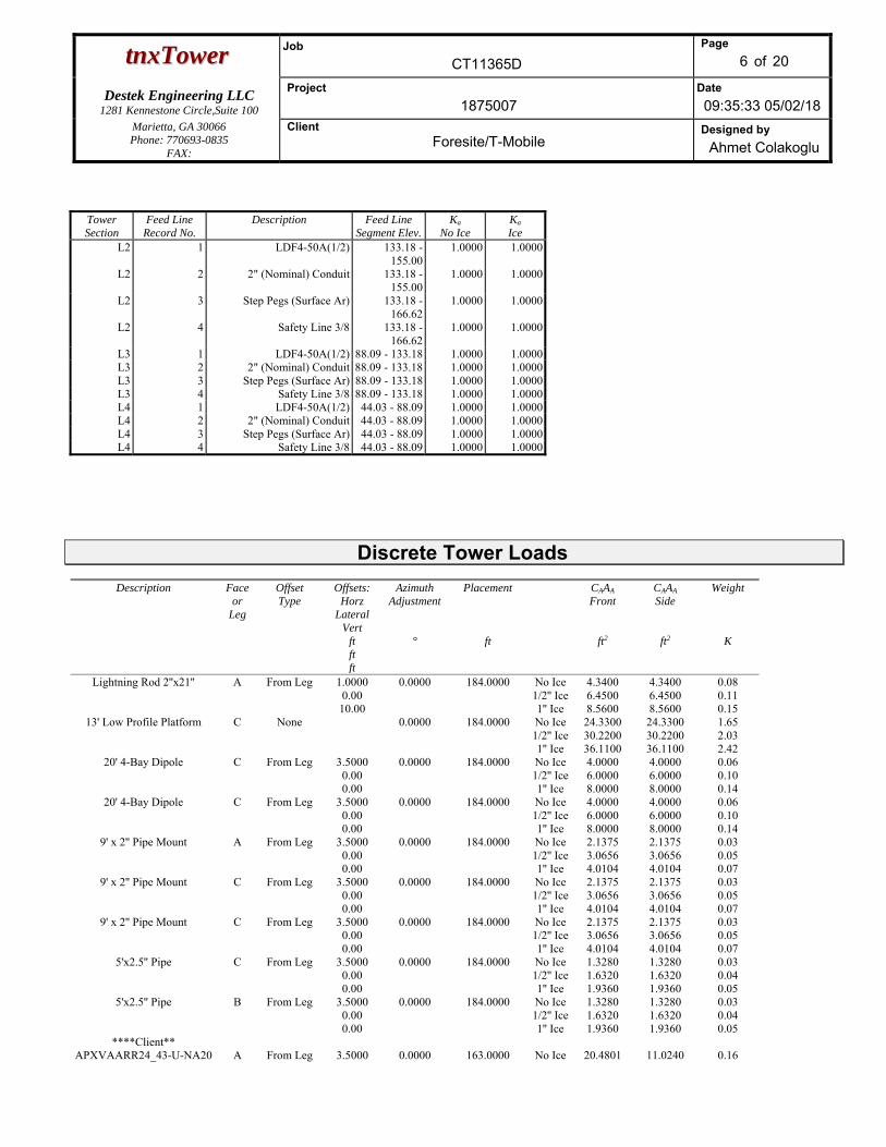
Tower Section
Feed Line Record No.
Description Feed Line Segment Elev.
Ka No Ice
Ka Ice
L2 1 LDF4-50A(1/2) 133.18 -155.00
1.0000 1.0000
L2 2 2" (Nominal) Conduit 133.18 -155.00
1.0000 1.0000
L2 3 Step Pegs (Surface Ar) 133.18 -166.62
1.0000 1.0000
L2 4 Safety Line 3/8 133.18 -166.62
1.0000 1.0000
L3 1 LDF4-50A(1/2) 88.09 - 133.18 1.0000 1.0000L3 2 2" (Nominal) Conduit 88.09 - 133.18 1.0000 1.0000L3 3 Step Pegs (Surface Ar) 88.09 - 133.18 1.0000 1.0000L3 4 Safety Line 3/8 88.09 - 133.18 1.0000 1.0000L4 1 LDF4-50A(1/2) 44.03 - 88.09 1.0000 1.0000L4 2 2" (Nominal) Conduit 44.03 - 88.09 1.0000 1.0000L4 3 Step Pegs (Surface Ar) 44.03 - 88.09 1.0000 1.0000L4 4 Safety Line 3/8 44.03 - 88.09 1.0000 1.0000
Discrete Tower Loads
Description Face or
Leg
Offset Type
Offsets: Horz
Lateral Vert
ft ft ft
Azimuth Adjustment
°
Placement
ft
CAAA Front
ft2
CAAA Side
ft2
Weight
K
Lightning Rod 2''x21'' A From Leg 1.0000 0.00 10.00
0.0000 184.0000 No Ice 1/2'' Ice1'' Ice
4.3400 6.4500 8.5600
4.3400 6.4500 8.5600
0.08 0.11 0.15
13' Low Profile Platform C None 0.0000 184.0000 No Ice 1/2'' Ice1'' Ice
24.3300 30.2200 36.1100
24.3300 30.2200 36.1100
1.65 2.03 2.42
20' 4-Bay Dipole C From Leg 3.5000 0.00 0.00
0.0000 184.0000 No Ice 1/2'' Ice1'' Ice
4.0000 6.0000 8.0000
4.0000 6.0000 8.0000
0.06 0.10 0.14
20' 4-Bay Dipole C From Leg 3.5000 0.00 0.00
0.0000 184.0000 No Ice 1/2'' Ice1'' Ice
4.0000 6.0000 8.0000
4.0000 6.0000 8.0000
0.06 0.10 0.14
9' x 2'' Pipe Mount A From Leg 3.5000 0.00 0.00
0.0000 184.0000 No Ice 1/2'' Ice1'' Ice
2.1375 3.0656 4.0104
2.1375 3.0656 4.0104
0.03 0.05 0.07
9' x 2'' Pipe Mount C From Leg 3.5000 0.00 0.00
0.0000 184.0000 No Ice 1/2'' Ice1'' Ice
2.1375 3.0656 4.0104
2.1375 3.0656 4.0104
0.03 0.05 0.07
9' x 2'' Pipe Mount C From Leg 3.5000 0.00 0.00
0.0000 184.0000 No Ice 1/2'' Ice1'' Ice
2.1375 3.0656 4.0104
2.1375 3.0656 4.0104
0.03 0.05 0.07
5'x2.5'' Pipe C From Leg 3.5000 0.00 0.00
0.0000 184.0000 No Ice 1/2'' Ice1'' Ice
1.3280 1.6320 1.9360
1.3280 1.6320 1.9360
0.03 0.04 0.05
5'x2.5'' Pipe B From Leg 3.5000 0.00 0.00
0.0000 184.0000 No Ice 1/2'' Ice1'' Ice
1.3280 1.6320 1.9360
1.3280 1.6320 1.9360
0.03 0.04 0.05
****Client** APXVAARR24_43-U-NA20 A From Leg 3.5000 0.0000 163.0000 No Ice 20.4801 11.0240 0.16
ttnnxxTToowweerr Job
CT11365D
Page
7 of 20
Destek Engineering LLC 1281 Kennestone Circle,Suite 100
Project
1875007 Date
09:35:33 05/02/18 Marietta, GA 30066 Phone: 770693-0835
FAX:
Client Foresite/T-Mobile
Designed by
Ahmet Colakoglu
Description Face or
Leg
Offset Type
Offsets: Horz
Lateral Vert
ft ft ft
Azimuth Adjustment
°
Placement
ft
CAAA Front
ft2
CAAA Side
ft2
Weight
K
w/ Mount Pipe 0.00 0.00
1/2'' Ice1'' Ice
21.2306 21.9900
12.5496 14.0992
0.30 0.44
APXVAARR24_43-U-NA20 w/ Mount Pipe
B From Leg 3.5000 0.00 0.00
0.0000 163.0000 No Ice 1/2'' Ice1'' Ice
20.4801 21.2306 21.9900
11.0240 12.5496 14.0992
0.16 0.30 0.44
APXVAARR24_43-U-NA20 w/ Mount Pipe
C From Leg 3.5000 0.00 0.00
0.0000 163.0000 No Ice 1/2'' Ice1'' Ice
20.4801 21.2306 21.9900
11.0240 12.5496 14.0992
0.16 0.30 0.44
RADIO 4449 A From Leg 3.5000 0.00 0.00
0.0000 163.0000 No Ice 1/2'' Ice1'' Ice
3.5000 3.7426 3.9926
2.3593 2.5658 2.7794
0.09 0.11 0.15
RADIO 4449 B From Leg 3.5000 0.00 0.00
0.0000 163.0000 No Ice 1/2'' Ice1'' Ice
3.5000 3.7426 3.9926
2.3593 2.5658 2.7794
0.09 0.11 0.15
RADIO 4449 C From Leg 3.5000 0.00 0.00
0.0000 163.0000 No Ice 1/2'' Ice1'' Ice
3.5000 3.7426 3.9926
2.3593 2.5658 2.7794
0.09 0.11 0.15
AIR 32 B2a/B66Aa B2a w/ Mount Pipe
A From Leg 3.5000 0.00 0.00
0.0000 163.0000 No Ice 1/2'' Ice1'' Ice
6.8150 7.2990 7.7830
6.1370 6.9930 7.8490
0.15 0.22 0.28
AIR 32 B2a/B66Aa B2a w/ Mount Pipe
B From Leg 3.5000 0.00 0.00
0.0000 163.0000 No Ice 1/2'' Ice1'' Ice
6.8150 7.2990 7.7830
6.1370 6.9930 7.8490
0.15 0.22 0.28
AIR 32 B2a/B66Aa B2a w/ Mount Pipe
C From Leg 3.5000 0.00 0.00
0.0000 163.0000 No Ice 1/2'' Ice1'' Ice
6.8150 7.2990 7.7830
6.1370 6.9930 7.8490
0.15 0.22 0.28
AIR 3246 B66 A From Leg 0.0000 0.00 0.00
0.0000 163.0000 No Ice 1/2'' Ice1'' Ice
8.0958 8.5429 8.9901
6.4779 7.2440 7.9590
0.20 0.27 0.35
AIR 3246 B66 B From Leg 0.0000 0.00 0.00
0.0000 163.0000 No Ice 1/2'' Ice1'' Ice
8.0958 8.5429 8.9901
6.4779 7.2440 7.9590
0.20 0.27 0.35
AIR 3246 B66 C From Leg 0.0000 0.00 0.00
0.0000 163.0000 No Ice 1/2'' Ice1'' Ice
8.0958 8.5429 8.9901
6.4779 7.2440 7.9590
0.20 0.27 0.35
KRY 112 144/2 A From Leg 3.0000 0.00 0.00
0.0000 163.0000 No Ice 1/2'' Ice1'' Ice
0.4794 0.5681 0.6642
0.2317 0.2994 0.3763
0.01 0.01 0.02
KRY 112 144/2 B From Leg 3.0000 0.00 0.00
0.0000 163.0000 No Ice 1/2'' Ice1'' Ice
0.4794 0.5681 0.6642
0.2317 0.2994 0.3763
0.01 0.01 0.02
KRY 112 144/2 C From Leg 3.0000 0.00 0.00
0.0000 163.0000 No Ice 1/2'' Ice1'' Ice
0.4794 0.5681 0.6642
0.2317 0.2994 0.3763
0.01 0.01 0.02
IBR 1300 Series A From Leg 3.0000 0.00 0.00
0.0000 163.0000 No Ice 1/2'' Ice1'' Ice
0.6709 0.7752 0.8868
0.2322 0.2993 0.3738
0.01 0.01 0.02
14 ft Handrail kit C None 0.0000 163.0000 No Ice 1/2'' Ice1'' Ice
6.0000 9.0000 12.0000
8.5000 12.7500 17.0000
0.26 0.34 0.42
14' Platform C None 0.0000 163.0000 No Ice 1/2'' Ice1'' Ice
23.1000 26.8000 30.5000
23.1000 26.8000 30.5000
2.10 2.50 2.90
***153*** APXVSPP18-C w/ Mount
Pipe A From Leg 3.5000
0.00 0.00
0.0000 154.0000 No Ice 1/2'' Ice1'' Ice
8.2619 8.8215 9.3462
6.9458 8.1266 9.0212
0.08 0.15 0.23
ttnnxxTToowweerr Job
CT11365D
Page
8 of 20
Destek Engineering LLC 1281 Kennestone Circle,Suite 100
Project
1875007 Date
09:35:33 05/02/18 Marietta, GA 30066 Phone: 770693-0835
FAX:
Client Foresite/T-Mobile
Designed by
Ahmet Colakoglu
Description Face or
Leg
Offset Type
Offsets: Horz
Lateral Vert
ft ft ft
Azimuth Adjustment
°
Placement
ft
CAAA Front
ft2
CAAA Side
ft2
Weight
K
APXVSPP18-C w/ Mount Pipe
B From Leg 3.5000 0.00 0.00
0.0000 154.0000 No Ice 1/2'' Ice1'' Ice
8.2619 8.8215 9.3462
6.9458 8.1266 9.0212
0.08 0.15 0.23
APXVSPP18-C w/ Mount Pipe
C From Leg 3.5000 0.00 0.00
0.0000 154.0000 No Ice 1/2'' Ice1'' Ice
8.2619 8.8215 9.3462
6.9458 8.1266 9.0212
0.08 0.15 0.23
(2) RRH1900MHz A From Leg 1.0000 0.00 0.00
0.0000 154.0000 No Ice 1/2'' Ice1'' Ice
2.5985 2.8392 3.0895
3.7161 4.1008 4.5022
0.06 0.10 0.14
(2) RRH1900MHz B From Leg 1.0000 0.00 0.00
0.0000 154.0000 No Ice 1/2'' Ice1'' Ice
2.5985 2.8392 3.0895
3.7161 4.1008 4.5022
0.06 0.10 0.14
(2) RRH1900MHz C From Leg 1.0000 0.00 0.00
0.0000 154.0000 No Ice 1/2'' Ice1'' Ice
2.5985 2.8392 3.0895
3.7161 4.1008 4.5022
0.06 0.10 0.14
RRH800MHz A From Leg 1.0000 0.00 0.00
0.0000 154.0000 No Ice 1/2'' Ice1'' Ice
2.2433 2.4881 2.7439
2.4095 2.7501 3.1073
0.05 0.08 0.11
RRH800MHz B From Leg 1.0000 0.00 0.00
0.0000 154.0000 No Ice 1/2'' Ice1'' Ice
2.2433 2.4881 2.7439
2.4095 2.7501 3.1073
0.05 0.08 0.11
RRH800MHz C From Leg 1.0000 0.00 0.00
0.0000 154.0000 No Ice 1/2'' Ice1'' Ice
2.2433 2.4881 2.7439
2.4095 2.7501 3.1073
0.05 0.08 0.11
13' Low Profile Platform C None 0.0000 154.0000 No Ice 1/2'' Ice1'' Ice
24.3300 30.2200 36.1100
24.3300 30.2200 36.1100
1.65 2.03 2.42
APXVTM14-ALU-I20 w/ Mount Pipe
A From Leg 3.5000 0.00 0.00
0.0000 154.0000 No Ice 1/2'' Ice1'' Ice
6.5799 7.0306 7.4733
4.9591 5.7544 6.4723
0.08 0.13 0.19
APXVTM14-ALU-I20 w/ Mount Pipe
B From Leg 3.5000 0.00 0.00
0.0000 154.0000 No Ice 1/2'' Ice1'' Ice
6.5799 7.0306 7.4733
4.9591 5.7544 6.4723
0.08 0.13 0.19
APXVTM14-ALU-I20 w/ Mount Pipe
C From Leg 3.5000 0.00 0.00
0.0000 154.0000 No Ice 1/2'' Ice1'' Ice
6.5799 7.0306 7.4733
4.9591 5.7544 6.4723
0.08 0.13 0.19
***151 TD-RRH8x20-25 A From Leg 1.0000
0.00 0.00
0.0000 154.0000 No Ice 1/2'' Ice1'' Ice
4.0455 4.2975 4.5570
1.5345 1.7142 1.9008
0.07 0.10 0.13
TD-RRH8x20-25 B From Leg 1.0000 0.00 0.00
0.0000 154.0000 No Ice 1/2'' Ice1'' Ice
4.0455 4.2975 4.5570
1.5345 1.7142 1.9008
0.07 0.10 0.13
TD-RRH8x20-25 C From Leg 1.0000 0.00 0.00
0.0000 154.0000 No Ice 1/2'' Ice1'' Ice
4.0455 4.2975 4.5570
1.5345 1.7142 1.9008
0.07 0.10 0.13
Ring Mount C None 0.0000 154.0000 No Ice 1/2'' Ice1'' Ice
4.3900 5.4800 6.5700
4.3900 5.4800 6.5700
0.20 0.24 0.28
**** **143**
13' Low Profile Platform A None 0.0000 144.0000 No Ice 1/2'' Ice1'' Ice
24.3300 30.2200 36.1100
24.3300 30.2200 36.1100
1.65 2.03 2.42
800 10121 w/ Mount Pipe A From Leg 3.5000 0.00 0.00
0.0000 144.0000 No Ice 1/2'' Ice1'' Ice
5.3879 5.8131 6.2340
4.5996 5.3507 6.0464
0.07 0.11 0.17
ttnnxxTToowweerr Job
CT11365D
Page
9 of 20
Destek Engineering LLC 1281 Kennestone Circle,Suite 100
Project
1875007 Date
09:35:33 05/02/18 Marietta, GA 30066 Phone: 770693-0835
FAX:
Client Foresite/T-Mobile
Designed by
Ahmet Colakoglu
Description Face or
Leg
Offset Type
Offsets: Horz
Lateral Vert
ft ft ft
Azimuth Adjustment
°
Placement
ft
CAAA Front
ft2
CAAA Side
ft2
Weight
K
800 10121 w/ Mount Pipe B From Leg 3.5000 0.00 0.00
0.0000 144.0000 No Ice 1/2'' Ice1'' Ice
5.3879 5.8131 6.2340
4.5996 5.3507 6.0464
0.07 0.11 0.17
800 10121 w/ Mount Pipe C From Leg 3.5000 0.00 0.00
0.0000 144.0000 No Ice 1/2'' Ice1'' Ice
5.3879 5.8131 6.2340
4.5996 5.3507 6.0464
0.07 0.11 0.17
RRUS 11 A From Leg 2.5000 0.00 0.00
0.0000 144.0000 No Ice 1/2'' Ice1'' Ice
2.7845 2.9919 3.2066
1.1872 1.3342 1.4897
0.05 0.07 0.10
RRUS 11 B From Leg 2.5000 0.00 0.00
0.0000 144.0000 No Ice 1/2'' Ice1'' Ice
2.7845 2.9919 3.2066
1.1872 1.3342 1.4897
0.05 0.07 0.10
RRUS 11 C From Leg 2.5000 0.00 0.00
0.0000 144.0000 No Ice 1/2'' Ice1'' Ice
2.7845 2.9919 3.2066
1.1872 1.3342 1.4897
0.05 0.07 0.10
RRUS 12 A From Leg 2.5000 0.00 0.00
0.0000 144.0000 No Ice 1/2'' Ice1'' Ice
3.1450 3.3648 3.5920
1.2854 1.4379 1.5998
0.06 0.08 0.11
RRUS 12 B From Leg 2.5000 0.00 0.00
0.0000 144.0000 No Ice 1/2'' Ice1'' Ice
3.1450 3.3648 3.5920
1.2854 1.4379 1.5998
0.06 0.08 0.11
RRUS 12 C From Leg 2.5000 0.00 0.00
0.0000 144.0000 No Ice 1/2'' Ice1'' Ice
3.1450 3.3648 3.5920
1.2854 1.4379 1.5998
0.06 0.08 0.11
DC6-48-60-18-8F C From Leg 2.0000 0.00 0.00
0.0000 144.0000 No Ice 1/2'' Ice1'' Ice
0.7915 1.2743 1.4503
0.7915 1.2743 1.4503
0.02 0.03 0.05
(2) OPA-65R-LCUU-H6 w/ Mount Pipe
A From Leg 3.5000 0.00 0.00
0.0000 144.0000 No Ice 1/2'' Ice1'' Ice
9.8953 10.4700 11.0098
7.1792 8.3621 9.2588
0.10 0.18 0.26
(2) OPA-65R-LCUU-H8 w/ Mount Pipe
B From Leg 3.5000 0.00 0.00
0.0000 144.0000 No Ice 1/2'' Ice1'' Ice
12.9838 13.6685 14.3572
9.3187 10.7901 12.2416
0.12 0.21 0.32
(2) OPA-65R-LCUU-H8 w/ Mount Pipe
C From Leg 3.5000 0.00 0.00
0.0000 144.0000 No Ice 1/2'' Ice1'' Ice
12.9838 13.6685 14.3572
9.3187 10.7901 12.2416
0.12 0.21 0.32
RRUS 32 A From Leg 2.5000 0.00 0.00
0.0000 144.0000 No Ice 1/2'' Ice1'' Ice
2.8571 3.0830 3.3163
1.7766 1.9677 2.1658
0.06 0.08 0.10
RRUS 32 B From Leg 2.5000 0.00 0.00
0.0000 144.0000 No Ice 1/2'' Ice1'' Ice
2.8571 3.0830 3.3163
1.7766 1.9677 2.1658
0.06 0.08 0.10
RRUS 32 C From Leg 2.5000 0.00 0.00
0.0000 144.0000 No Ice 1/2'' Ice1'' Ice
2.8571 3.0830 3.3163
1.7766 1.9677 2.1658
0.06 0.08 0.10
RRUS E2 B29 A From Leg 2.5000 0.00 0.00
0.0000 144.0000 No Ice 1/2'' Ice1'' Ice
3.1450 3.3648 3.5920
1.2854 1.4379 1.5998
0.06 0.08 0.11
RRUS E2 B29 B From Leg 2.5000 0.00 0.00
0.0000 144.0000 No Ice 1/2'' Ice1'' Ice
3.1450 3.3648 3.5920
1.2854 1.4379 1.5998
0.06 0.08 0.11
RRUS E2 B29 C From Leg 2.5000 0.00 0.00
0.0000 144.0000 No Ice 1/2'' Ice1'' Ice
3.1450 3.3648 3.5920
1.2854 1.4379 1.5998
0.06 0.08 0.11
RRUS A2 A From Leg 2.5000 0.00 0.00
0.0000 144.0000 No Ice 1/2'' Ice1'' Ice
2.0663 2.2451 2.4313
0.5050 0.6151 0.7322
0.02 0.03 0.05
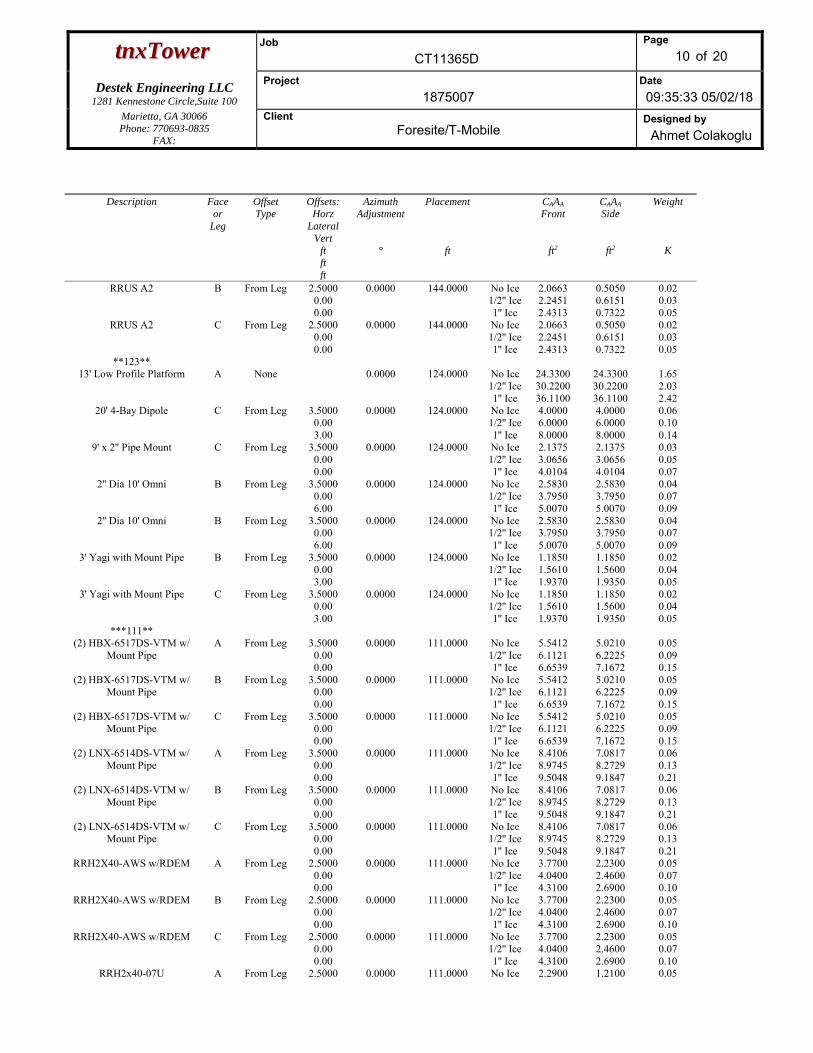
ttnnxxTToowweerr Job
CT11365D
Page
10 of 20
Destek Engineering LLC 1281 Kennestone Circle,Suite 100
Project
1875007 Date
09:35:33 05/02/18 Marietta, GA 30066 Phone: 770693-0835
FAX:
Client Foresite/T-Mobile
Designed by
Ahmet Colakoglu
Description Face or
Leg
Offset Type
Offsets: Horz
Lateral Vert
ft ft ft
Azimuth Adjustment
°
Placement
ft
CAAA Front
ft2
CAAA Side
ft2
Weight
K
RRUS A2 B From Leg 2.5000 0.00 0.00
0.0000 144.0000 No Ice 1/2'' Ice1'' Ice
2.0663 2.2451 2.4313
0.5050 0.6151 0.7322
0.02 0.03 0.05
RRUS A2 C From Leg 2.5000 0.00 0.00
0.0000 144.0000 No Ice 1/2'' Ice1'' Ice
2.0663 2.2451 2.4313
0.5050 0.6151 0.7322
0.02 0.03 0.05
**123** 13' Low Profile Platform A None 0.0000 124.0000 No Ice
1/2'' Ice1'' Ice
24.3300 30.2200 36.1100
24.3300 30.2200 36.1100
1.65 2.03 2.42
20' 4-Bay Dipole C From Leg 3.5000 0.00 3.00
0.0000 124.0000 No Ice 1/2'' Ice1'' Ice
4.0000 6.0000 8.0000
4.0000 6.0000 8.0000
0.06 0.10 0.14
9' x 2'' Pipe Mount C From Leg 3.5000 0.00 0.00
0.0000 124.0000 No Ice 1/2'' Ice1'' Ice
2.1375 3.0656 4.0104
2.1375 3.0656 4.0104
0.03 0.05 0.07
2'' Dia 10' Omni B From Leg 3.5000 0.00 6.00
0.0000 124.0000 No Ice 1/2'' Ice1'' Ice
2.5830 3.7950 5.0070
2.5830 3.7950 5.0070
0.04 0.07 0.09
2'' Dia 10' Omni B From Leg 3.5000 0.00 6.00
0.0000 124.0000 No Ice 1/2'' Ice1'' Ice
2.5830 3.7950 5.0070
2.5830 3.7950 5.0070
0.04 0.07 0.09
3' Yagi with Mount Pipe B From Leg 3.5000 0.00 3.00
0.0000 124.0000 No Ice 1/2'' Ice1'' Ice
1.1850 1.5610 1.9370
1.1850 1.5600 1.9350
0.02 0.04 0.05
3' Yagi with Mount Pipe C From Leg 3.5000 0.00 3.00
0.0000 124.0000 No Ice 1/2'' Ice1'' Ice
1.1850 1.5610 1.9370
1.1850 1.5600 1.9350
0.02 0.04 0.05
***111** (2) HBX-6517DS-VTM w/
Mount Pipe A From Leg 3.5000
0.00 0.00
0.0000 111.0000 No Ice 1/2'' Ice1'' Ice
5.5412 6.1121 6.6539
5.0210 6.2225 7.1672
0.05 0.09 0.15
(2) HBX-6517DS-VTM w/ Mount Pipe
B From Leg 3.5000 0.00 0.00
0.0000 111.0000 No Ice 1/2'' Ice1'' Ice
5.5412 6.1121 6.6539
5.0210 6.2225 7.1672
0.05 0.09 0.15
(2) HBX-6517DS-VTM w/ Mount Pipe
C From Leg 3.5000 0.00 0.00
0.0000 111.0000 No Ice 1/2'' Ice1'' Ice
5.5412 6.1121 6.6539
5.0210 6.2225 7.1672
0.05 0.09 0.15
(2) LNX-6514DS-VTM w/ Mount Pipe
A From Leg 3.5000 0.00 0.00
0.0000 111.0000 No Ice 1/2'' Ice1'' Ice
8.4106 8.9745 9.5048
7.0817 8.2729 9.1847
0.06 0.13 0.21
(2) LNX-6514DS-VTM w/ Mount Pipe
B From Leg 3.5000 0.00 0.00
0.0000 111.0000 No Ice 1/2'' Ice1'' Ice
8.4106 8.9745 9.5048
7.0817 8.2729 9.1847
0.06 0.13 0.21
(2) LNX-6514DS-VTM w/ Mount Pipe
C From Leg 3.5000 0.00 0.00
0.0000 111.0000 No Ice 1/2'' Ice1'' Ice
8.4106 8.9745 9.5048
7.0817 8.2729 9.1847
0.06 0.13 0.21
RRH2X40-AWS w/RDEM A From Leg 2.5000 0.00 0.00
0.0000 111.0000 No Ice 1/2'' Ice1'' Ice
3.7700 4.0400 4.3100
2.2300 2.4600 2.6900
0.05 0.07 0.10
RRH2X40-AWS w/RDEM B From Leg 2.5000 0.00 0.00
0.0000 111.0000 No Ice 1/2'' Ice1'' Ice
3.7700 4.0400 4.3100
2.2300 2.4600 2.6900
0.05 0.07 0.10
RRH2X40-AWS w/RDEM C From Leg 2.5000 0.00 0.00
0.0000 111.0000 No Ice 1/2'' Ice1'' Ice
3.7700 4.0400 4.3100
2.2300 2.4600 2.6900
0.05 0.07 0.10
RRH2x40-07U A From Leg 2.5000 0.0000 111.0000 No Ice 2.2900 1.2100 0.05
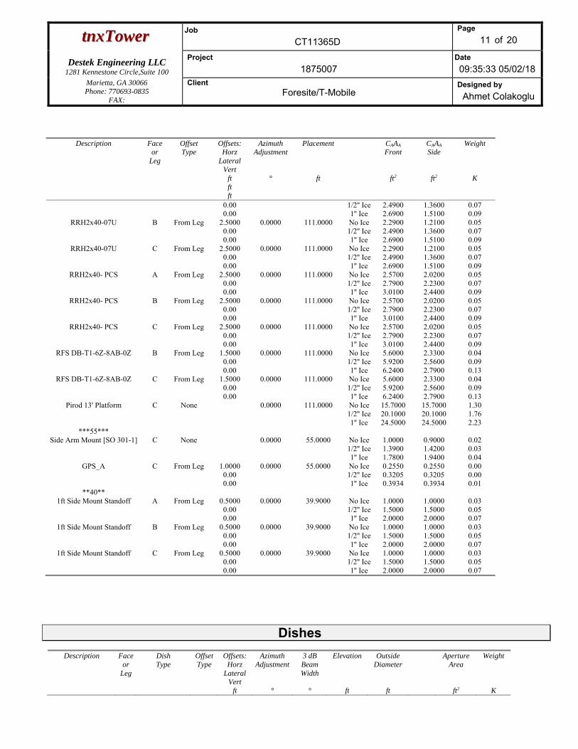
ttnnxxTToowweerr Job
CT11365D
Page
11 of 20
Destek Engineering LLC 1281 Kennestone Circle,Suite 100
Project
1875007 Date
09:35:33 05/02/18 Marietta, GA 30066 Phone: 770693-0835
FAX:
Client Foresite/T-Mobile
Designed by
Ahmet Colakoglu
Description Face or
Leg
Offset Type
Offsets: Horz
Lateral Vert
ft ft ft
Azimuth Adjustment
°
Placement
ft
CAAA Front
ft2
CAAA Side
ft2
Weight
K
0.00 0.00
1/2'' Ice1'' Ice
2.4900 2.6900
1.3600 1.5100
0.07 0.09
RRH2x40-07U B From Leg 2.5000 0.00 0.00
0.0000 111.0000 No Ice 1/2'' Ice1'' Ice
2.2900 2.4900 2.6900
1.2100 1.3600 1.5100
0.05 0.07 0.09
RRH2x40-07U C From Leg 2.5000 0.00 0.00
0.0000 111.0000 No Ice 1/2'' Ice1'' Ice
2.2900 2.4900 2.6900
1.2100 1.3600 1.5100
0.05 0.07 0.09
RRH2x40- PCS A From Leg 2.5000 0.00 0.00
0.0000 111.0000 No Ice 1/2'' Ice1'' Ice
2.5700 2.7900 3.0100
2.0200 2.2300 2.4400
0.05 0.07 0.09
RRH2x40- PCS B From Leg 2.5000 0.00 0.00
0.0000 111.0000 No Ice 1/2'' Ice1'' Ice
2.5700 2.7900 3.0100
2.0200 2.2300 2.4400
0.05 0.07 0.09
RRH2x40- PCS C From Leg 2.5000 0.00 0.00
0.0000 111.0000 No Ice 1/2'' Ice1'' Ice
2.5700 2.7900 3.0100
2.0200 2.2300 2.4400
0.05 0.07 0.09
RFS DB-T1-6Z-8AB-0Z B From Leg 1.5000 0.00 0.00
0.0000 111.0000 No Ice 1/2'' Ice1'' Ice
5.6000 5.9200 6.2400
2.3300 2.5600 2.7900
0.04 0.09 0.13
RFS DB-T1-6Z-8AB-0Z C From Leg 1.5000 0.00 0.00
0.0000 111.0000 No Ice 1/2'' Ice1'' Ice
5.6000 5.9200 6.2400
2.3300 2.5600 2.7900
0.04 0.09 0.13
Pirod 13' Platform C None 0.0000 111.0000 No Ice 1/2'' Ice1'' Ice
15.7000 20.1000 24.5000
15.7000 20.1000 24.5000
1.30 1.76 2.23
***55*** Side Arm Mount [SO 301-1] C None 0.0000 55.0000 No Ice
1/2'' Ice1'' Ice
1.0000 1.3900 1.7800
0.9000 1.4200 1.9400
0.02 0.03 0.04
GPS_A C From Leg 1.0000 0.00 0.00
0.0000 55.0000 No Ice 1/2'' Ice1'' Ice
0.2550 0.3205 0.3934
0.2550 0.3205 0.3934
0.00 0.00 0.01
**40** 1ft Side Mount Standoff A From Leg 0.5000
0.00 0.00
0.0000 39.9000 No Ice 1/2'' Ice1'' Ice
1.0000 1.5000 2.0000
1.0000 1.5000 2.0000
0.03 0.05 0.07
1ft Side Mount Standoff B From Leg 0.5000 0.00 0.00
0.0000 39.9000 No Ice 1/2'' Ice1'' Ice
1.0000 1.5000 2.0000
1.0000 1.5000 2.0000
0.03 0.05 0.07
1ft Side Mount Standoff C From Leg 0.5000 0.00 0.00
0.0000 39.9000 No Ice 1/2'' Ice1'' Ice
1.0000 1.5000 2.0000
1.0000 1.5000 2.0000
0.03 0.05 0.07
Dishes
Description Face or
Leg
Dish Type
Offset Type
Offsets: Horz
LateralVert
ft
Azimuth Adjustment
°
3 dB Beam Width
°
Elevation
ft
Outside Diameter
ft
Aperture Area
ft2
Weight
K
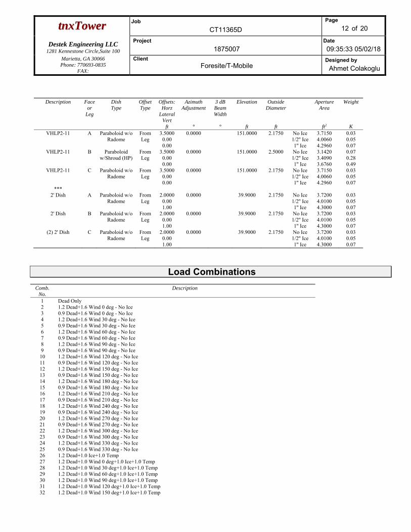
ttnnxxTToowweerr Job
CT11365D
Page
12 of 20
Destek Engineering LLC 1281 Kennestone Circle,Suite 100
Project
1875007 Date
09:35:33 05/02/18 Marietta, GA 30066 Phone: 770693-0835
FAX:
Client Foresite/T-Mobile
Designed by
Ahmet Colakoglu
Description Face or
Leg
Dish Type
Offset Type
Offsets: Horz
LateralVert
ft
Azimuth Adjustment
°
3 dB Beam Width
°
Elevation
ft
Outside Diameter
ft
Aperture Area
ft2
Weight
KVHLP2-11 A Paraboloid w/o
Radome From Leg
3.5000 0.00 0.00
0.0000 151.0000 2.1750 No Ice 1/2'' Ice 1'' Ice
3.7150 4.0060 4.2960
0.03 0.05 0.07
VHLP2-11 B Paraboloid w/Shroud (HP)
From Leg
3.5000 0.00 0.00
0.0000 151.0000 2.5000 No Ice 1/2'' Ice 1'' Ice
3.1420 3.4090 3.6760
0.07 0.28 0.49
VHLP2-11 C Paraboloid w/o Radome
From Leg
3.5000 0.00 0.00
0.0000 151.0000 2.1750 No Ice 1/2'' Ice 1'' Ice
3.7150 4.0060 4.2960
0.03 0.05 0.07
*** 2' Dish A Paraboloid w/o
Radome From Leg
2.0000 0.00 1.00
0.0000 39.9000 2.1750 No Ice 1/2'' Ice 1'' Ice
3.7200 4.0100 4.3000
0.03 0.05 0.07
2' Dish B Paraboloid w/o Radome
From Leg
2.0000 0.00 1.00
0.0000 39.9000 2.1750 No Ice 1/2'' Ice 1'' Ice
3.7200 4.0100 4.3000
0.03 0.05 0.07
(2) 2' Dish C Paraboloid w/o Radome
From Leg
2.0000 0.00 1.00
0.0000 39.9000 2.1750 No Ice 1/2'' Ice 1'' Ice
3.7200 4.0100 4.3000
0.03 0.05 0.07
Load Combinations Comb.
No. Description
1 Dead Only 2 1.2 Dead+1.6 Wind 0 deg - No Ice 3 0.9 Dead+1.6 Wind 0 deg - No Ice 4 1.2 Dead+1.6 Wind 30 deg - No Ice 5 0.9 Dead+1.6 Wind 30 deg - No Ice 6 1.2 Dead+1.6 Wind 60 deg - No Ice 7 0.9 Dead+1.6 Wind 60 deg - No Ice 8 1.2 Dead+1.6 Wind 90 deg - No Ice 9 0.9 Dead+1.6 Wind 90 deg - No Ice 10 1.2 Dead+1.6 Wind 120 deg - No Ice 11 0.9 Dead+1.6 Wind 120 deg - No Ice 12 1.2 Dead+1.6 Wind 150 deg - No Ice 13 0.9 Dead+1.6 Wind 150 deg - No Ice 14 1.2 Dead+1.6 Wind 180 deg - No Ice 15 0.9 Dead+1.6 Wind 180 deg - No Ice 16 1.2 Dead+1.6 Wind 210 deg - No Ice 17 0.9 Dead+1.6 Wind 210 deg - No Ice 18 1.2 Dead+1.6 Wind 240 deg - No Ice 19 0.9 Dead+1.6 Wind 240 deg - No Ice 20 1.2 Dead+1.6 Wind 270 deg - No Ice 21 0.9 Dead+1.6 Wind 270 deg - No Ice 22 1.2 Dead+1.6 Wind 300 deg - No Ice 23 0.9 Dead+1.6 Wind 300 deg - No Ice 24 1.2 Dead+1.6 Wind 330 deg - No Ice 25 0.9 Dead+1.6 Wind 330 deg - No Ice 26 1.2 Dead+1.0 Ice+1.0 Temp 27 1.2 Dead+1.0 Wind 0 deg+1.0 Ice+1.0 Temp 28 1.2 Dead+1.0 Wind 30 deg+1.0 Ice+1.0 Temp 29 1.2 Dead+1.0 Wind 60 deg+1.0 Ice+1.0 Temp 30 1.2 Dead+1.0 Wind 90 deg+1.0 Ice+1.0 Temp 31 1.2 Dead+1.0 Wind 120 deg+1.0 Ice+1.0 Temp 32 1.2 Dead+1.0 Wind 150 deg+1.0 Ice+1.0 Temp
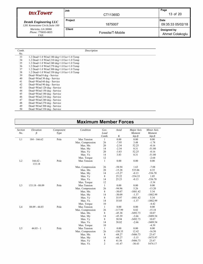
ttnnxxTToowweerr Job
CT11365D
Page
13 of 20
Destek Engineering LLC 1281 Kennestone Circle,Suite 100
Project
1875007 Date
09:35:33 05/02/18 Marietta, GA 30066 Phone: 770693-0835
FAX:
Client Foresite/T-Mobile
Designed by
Ahmet Colakoglu
Comb. No.
Description
33 1.2 Dead+1.0 Wind 180 deg+1.0 Ice+1.0 Temp 34 1.2 Dead+1.0 Wind 210 deg+1.0 Ice+1.0 Temp 35 1.2 Dead+1.0 Wind 240 deg+1.0 Ice+1.0 Temp 36 1.2 Dead+1.0 Wind 270 deg+1.0 Ice+1.0 Temp 37 1.2 Dead+1.0 Wind 300 deg+1.0 Ice+1.0 Temp 38 1.2 Dead+1.0 Wind 330 deg+1.0 Ice+1.0 Temp 39 Dead+Wind 0 deg - Service 40 Dead+Wind 30 deg - Service 41 Dead+Wind 60 deg - Service 42 Dead+Wind 90 deg - Service 43 Dead+Wind 120 deg - Service44 Dead+Wind 150 deg - Service45 Dead+Wind 180 deg - Service46 Dead+Wind 210 deg - Service47 Dead+Wind 240 deg - Service48 Dead+Wind 270 deg - Service49 Dead+Wind 300 deg - Service50 Dead+Wind 330 deg - Service
Maximum Member Forces Section
No. Elevation
ft Component
Type Condition Gov.
Load Comb.
Axial
K
Major Axis Moment
kip-ft
Minor Axis Moment
kip-ft L1 184 - 166.62 Pole Max Tension 1 0.00 0.00 0.00
Max. Compression 26 -7.95 3.48 -1.78 Max. Mx 20 -2.34 52.25 -0.16 Max. My 14 -2.34 0.31 -51.80 Max. Vy 20 -3.83 52.25 -0.16 Max. Vx 14 3.83 0.31 -51.80 Max. Torque 12 -2.64
L2 166.62 - 133.18
Pole Max Tension 1 0.00 0.00 0.00
Max. Compression 26 -58.94 1.63 -7.08 Max. Mx 20 -15.28 535.06 0.35 Max. My 14 -15.27 -0.13 -536.70 Max. Vy 8 25.22 -534.33 1.05 Max. Vx 14 25.23 -0.13 -536.70 Max. Torque 12 -3.34
L3 133.18 - 88.09 Pole Max Tension 1 0.00 0.00 0.00 Max. Compression 26 -94.96 5.26 -13.20 Max. Mx 8 -30.07 -1881.42 5.34 Max. My 14 -30.09 -1.37 -1882.99 Max. Vy 8 35.97 -1881.42 5.34 Max. Vx 14 35.85 -1.37 -1882.99 Max. Torque 10 -4.42
L4 88.09 - 44.03 Pole Max Tension 1 0.00 0.00 0.00 Max. Compression 26 -117.99 8.82 -15.18 Max. Mx 8 -45.38 -3492.73 10.07 Max. My 14 -45.39 -2.66 -3489.54 Max. Vy 8 38.94 -3492.73 10.07 Max. Vx 14 38.82 -2.66 -3489.54 Max. Torque 10 -4.39
L5 44.03 - 1 Pole Max Tension 1 0.00 0.00 0.00 Max. Compression 26 -150.35 12.42 -16.50 Max. Mx 8 -68.27 -5486.73 23.67 Max. My 14 -68.27 -3.15 -5475.97 Max. Vy 8 41.56 -5486.73 23.67 Max. Vx 2 -41.47 -30.43 5474.17
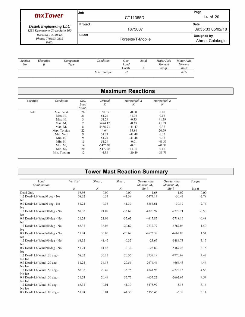
ttnnxxTToowweerr Job
CT11365D
Page
14 of 20
Destek Engineering LLC 1281 Kennestone Circle,Suite 100
Project
1875007 Date
09:35:33 05/02/18 Marietta, GA 30066 Phone: 770693-0835
FAX:
Client Foresite/T-Mobile
Designed by
Ahmet Colakoglu
Section No.
Elevation ft
Component Type
Condition Gov. Load
Comb.
Axial
K
Major Axis Moment
kip-ft
Minor Axis Moment
kip-ft Max. Torque 22 4.65
Maximum Reactions
Location Condition Gov. Load
Comb.
Vertical K
Horizontal, X K
Horizontal, Z K
Pole Max. Vert 26 150.35 -0.00 0.00 Max. Hx 21 51.24 41.36 0.16 Max. Hz 3 51.24 -0.33 41.39 Max. Mx 2 5474.17 -0.33 41.39 Max. Mz 8 5486.73 -41.47 0.32 Max. Torsion 22 4.64 35.86 20.59 Min. Vert 9 51.24 -41.48 0.32 Min. Hx 9 51.24 -41.48 0.32 Min. Hz 15 51.24 -0.01 -41.30 Min. Mx 14 -5475.97 -0.01 -41.30 Min. Mz 20 -5479.48 41.36 0.16 Min. Torsion 12 -4.58 -20.49 -35.75
Tower Mast Reaction Summary
Load Combination
Vertical
K
Shearx
K
Shearz
K
Overturning Moment, Mx
kip-ft
Overturning Moment, Mz
kip-ft
Torque
kip-ftDead Only 56.93 0.00 -0.00 1.68 1.02 0.001.2 Dead+1.6 Wind 0 deg - No Ice
68.32 0.33 -41.39 -5474.17 -30.43 -2.79
0.9 Dead+1.6 Wind 0 deg - No Ice
51.24 0.33 -41.39 -5354.61 -30.17 -2.76
1.2 Dead+1.6 Wind 30 deg - No Ice
68.32 21.09 -35.62 -4720.97 -2778.71 -0.50
0.9 Dead+1.6 Wind 30 deg - No Ice
51.24 21.09 -35.62 -4617.85 -2718.16 -0.48
1.2 Dead+1.6 Wind 60 deg - No Ice
68.32 36.06 -20.69 -2732.77 -4767.06 1.50
0.9 Dead+1.6 Wind 60 deg - No Ice
51.24 36.06 -20.69 -2673.38 -4662.85 1.51
1.2 Dead+1.6 Wind 90 deg - No Ice
68.32 41.47 -0.32 -23.67 -5486.73 3.17
0.9 Dead+1.6 Wind 90 deg - No Ice
51.24 41.48 -0.32 -23.82 -5367.23 3.16
1.2 Dead+1.6 Wind 120 deg - No Ice
68.32 36.13 20.56 2737.19 -4770.69 4.47
0.9 Dead+1.6 Wind 120 deg - No Ice
51.24 36.13 20.56 2676.46 -4666.43 4.44
1.2 Dead+1.6 Wind 150 deg - No Ice
68.32 20.49 35.75 4741.93 -2722.15 4.58
0.9 Dead+1.6 Wind 150 deg - No Ice
51.24 20.49 35.75 4637.22 -2662.67 4.54
1.2 Dead+1.6 Wind 180 deg - No Ice
68.32 0.01 41.30 5475.97 -3.15 3.14
0.9 Dead+1.6 Wind 180 deg - 51.24 0.01 41.30 5355.45 -3.38 3.11
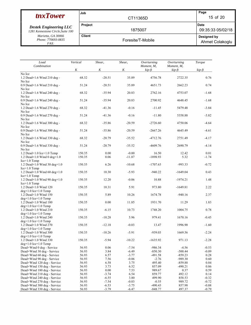
ttnnxxTToowweerr Job
CT11365D
Page
15 of 20
Destek Engineering LLC 1281 Kennestone Circle,Suite 100
Project
1875007 Date
09:35:33 05/02/18 Marietta, GA 30066 Phone: 770693-0835
FAX:
Client Foresite/T-Mobile
Designed by
Ahmet Colakoglu
Load Combination
Vertical
K
Shearx
K
Shearz
K
Overturning Moment, Mx
kip-ft
Overturning Moment, Mz
kip-ft
Torque
kip-ftNo Ice 1.2 Dead+1.6 Wind 210 deg - No Ice
68.32 -20.51 35.89 4756.78 2722.35 0.76
0.9 Dead+1.6 Wind 210 deg - No Ice
51.24 -20.51 35.89 4651.73 2662.23 0.74
1.2 Dead+1.6 Wind 240 deg - No Ice
68.32 -35.94 20.83 2762.16 4753.07 -1.68
0.9 Dead+1.6 Wind 240 deg - No Ice
51.24 -35.94 20.83 2700.92 4648.45 -1.68
1.2 Dead+1.6 Wind 270 deg - No Ice
68.32 -41.36 -0.16 -11.45 5479.48 -3.84
0.9 Dead+1.6 Wind 270 deg - No Ice
51.24 -41.36 -0.16 -11.80 5358.88 -3.82
1.2 Dead+1.6 Wind 300 deg - No Ice
68.32 -35.86 -20.59 -2726.60 4750.06 -4.64
0.9 Dead+1.6 Wind 300 deg - No Ice
51.24 -35.86 -20.59 -2667.26 4645.49 -4.61
1.2 Dead+1.6 Wind 330 deg - No Ice
68.32 -20.79 -35.52 -4712.76 2751.49 -4.17
0.9 Dead+1.6 Wind 330 deg - No Ice
51.24 -20.79 -35.52 -4609.76 2690.79 -4.14
1.2 Dead+1.0 Ice+1.0 Temp 150.35 0.00 -0.00 16.50 12.42 0.011.2 Dead+1.0 Wind 0 deg+1.0 Ice+1.0 Temp
150.35 0.06 -11.87 -1898.93 5.32 -1.74
1.2 Dead+1.0 Wind 30 deg+1.0 Ice+1.0 Temp
150.35 6.26 -10.68 -1707.63 -993.33 -0.72
1.2 Dead+1.0 Wind 60 deg+1.0 Ice+1.0 Temp
150.35 10.30 -5.93 -940.22 -1649.04 0.43
1.2 Dead+1.0 Wind 90 deg+1.0 Ice+1.0 Temp
150.35 12.20 -0.06 10.88 -1974.21 1.48
1.2 Dead+1.0 Wind 120 deg+1.0 Ice+1.0 Temp
150.35 10.31 5.91 973.80 -1649.81 2.22
1.2 Dead+1.0 Wind 150 deg+1.0 Ice+1.0 Temp
150.35 5.89 10.26 1674.78 -940.16 2.37
1.2 Dead+1.0 Wind 180 deg+1.0 Ice+1.0 Temp
150.35 0.00 11.85 1931.70 11.29 1.83
1.2 Dead+1.0 Wind 210 deg+1.0 Ice+1.0 Temp
150.35 -6.15 10.73 1748.20 1004.75 0.78
1.2 Dead+1.0 Wind 240 deg+1.0 Ice+1.0 Temp
150.35 -10.28 5.96 979.41 1670.16 -0.45
1.2 Dead+1.0 Wind 270 deg+1.0 Ice+1.0 Temp
150.35 -12.18 -0.03 13.47 1996.90 -1.60
1.2 Dead+1.0 Wind 300 deg+1.0 Ice+1.0 Temp
150.35 -10.26 -5.91 -939.03 1669.56 -2.24
1.2 Dead+1.0 Wind 330 deg+1.0 Ice+1.0 Temp
150.35 -5.94 -10.22 -1635.92 971.13 -2.28
Dead+Wind 0 deg - Service 56.93 0.06 -7.54 -986.34 -4.56 -0.53Dead+Wind 30 deg - Service 56.93 3.84 -6.49 -850.30 -500.44 -0.09Dead+Wind 60 deg - Service 56.93 6.57 -3.77 -491.58 -859.23 0.28Dead+Wind 90 deg - Service 56.93 7.56 -0.06 -2.76 -989.30 0.60Dead+Wind 120 deg - Service 56.93 6.58 3.75 495.40 -859.88 0.84Dead+Wind 150 deg - Service 56.93 3.73 6.52 857.09 -490.21 0.86Dead+Wind 180 deg - Service 56.93 0.00 7.53 989.67 0.37 0.59Dead+Wind 210 deg - Service 56.93 -3.74 6.54 859.77 492.12 0.14Dead+Wind 240 deg - Service 56.93 -6.55 3.80 499.90 858.53 -0.32Dead+Wind 270 deg - Service 56.93 -7.54 -0.03 -0.55 989.72 -0.72Dead+Wind 300 deg - Service 56.93 -6.53 -3.75 -490.43 857.98 -0.88Dead+Wind 330 deg - Service 56.93 -3.79 -6.47 -848.77 497.37 -0.79
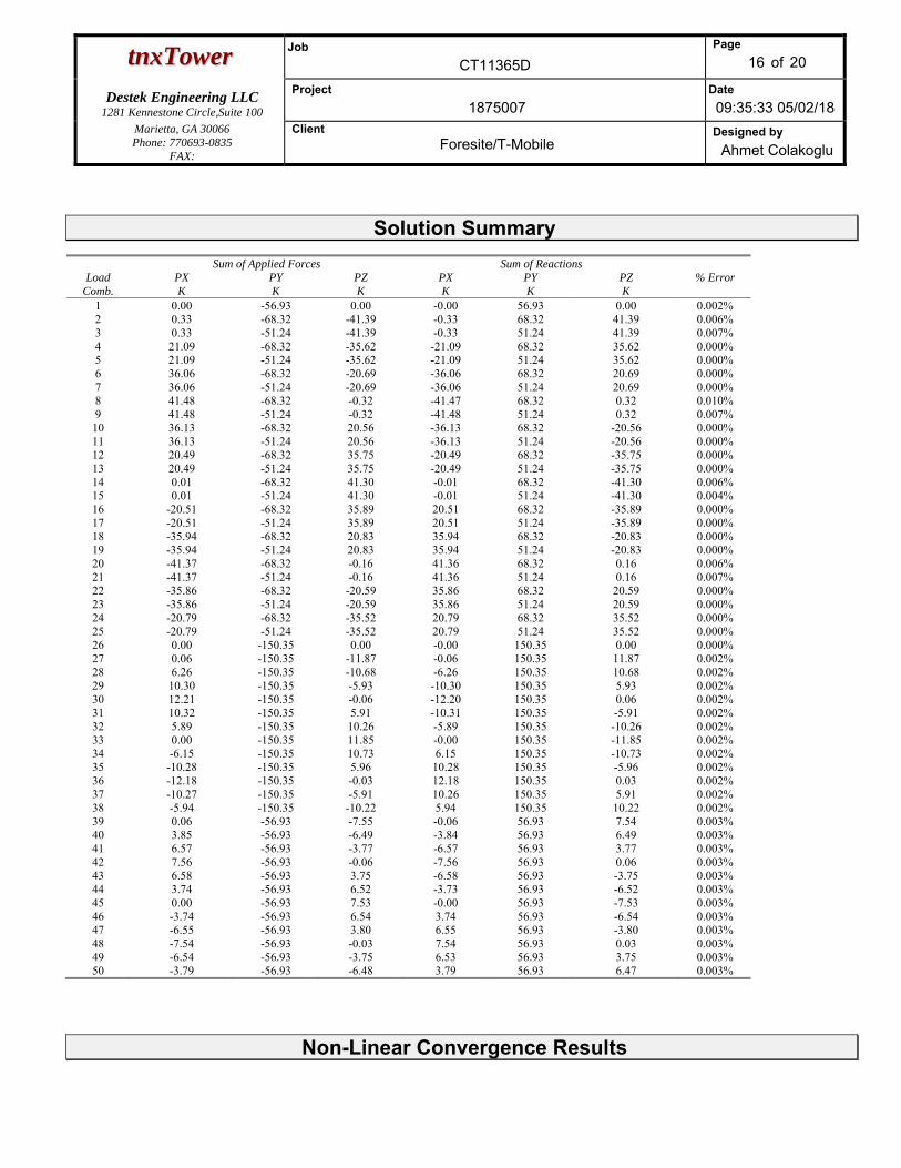
ttnnxxTToowweerr Job
CT11365D
Page
16 of 20
Destek Engineering LLC 1281 Kennestone Circle,Suite 100
Project
1875007 Date
09:35:33 05/02/18 Marietta, GA 30066 Phone: 770693-0835
FAX:
Client Foresite/T-Mobile
Designed by
Ahmet Colakoglu
Solution Summary
Load Comb.
Sum of Applied Forces Sum of Reactions % Error PX
K PY K
PZ K
PX K
PY K
PZ K
1 0.00 -56.93 0.00 -0.00 56.93 0.00 0.002%2 0.33 -68.32 -41.39 -0.33 68.32 41.39 0.006%3 0.33 -51.24 -41.39 -0.33 51.24 41.39 0.007%4 21.09 -68.32 -35.62 -21.09 68.32 35.62 0.000%5 21.09 -51.24 -35.62 -21.09 51.24 35.62 0.000%6 36.06 -68.32 -20.69 -36.06 68.32 20.69 0.000%7 36.06 -51.24 -20.69 -36.06 51.24 20.69 0.000%8 41.48 -68.32 -0.32 -41.47 68.32 0.32 0.010%9 41.48 -51.24 -0.32 -41.48 51.24 0.32 0.007%10 36.13 -68.32 20.56 -36.13 68.32 -20.56 0.000%11 36.13 -51.24 20.56 -36.13 51.24 -20.56 0.000%12 20.49 -68.32 35.75 -20.49 68.32 -35.75 0.000%13 20.49 -51.24 35.75 -20.49 51.24 -35.75 0.000%14 0.01 -68.32 41.30 -0.01 68.32 -41.30 0.006%15 0.01 -51.24 41.30 -0.01 51.24 -41.30 0.004%16 -20.51 -68.32 35.89 20.51 68.32 -35.89 0.000%17 -20.51 -51.24 35.89 20.51 51.24 -35.89 0.000%18 -35.94 -68.32 20.83 35.94 68.32 -20.83 0.000%19 -35.94 -51.24 20.83 35.94 51.24 -20.83 0.000%20 -41.37 -68.32 -0.16 41.36 68.32 0.16 0.006%21 -41.37 -51.24 -0.16 41.36 51.24 0.16 0.007%22 -35.86 -68.32 -20.59 35.86 68.32 20.59 0.000%23 -35.86 -51.24 -20.59 35.86 51.24 20.59 0.000%24 -20.79 -68.32 -35.52 20.79 68.32 35.52 0.000%25 -20.79 -51.24 -35.52 20.79 51.24 35.52 0.000%26 0.00 -150.35 0.00 -0.00 150.35 0.00 0.000%27 0.06 -150.35 -11.87 -0.06 150.35 11.87 0.002%28 6.26 -150.35 -10.68 -6.26 150.35 10.68 0.002%29 10.30 -150.35 -5.93 -10.30 150.35 5.93 0.002%30 12.21 -150.35 -0.06 -12.20 150.35 0.06 0.002%31 10.32 -150.35 5.91 -10.31 150.35 -5.91 0.002%32 5.89 -150.35 10.26 -5.89 150.35 -10.26 0.002%33 0.00 -150.35 11.85 -0.00 150.35 -11.85 0.002%34 -6.15 -150.35 10.73 6.15 150.35 -10.73 0.002%35 -10.28 -150.35 5.96 10.28 150.35 -5.96 0.002%36 -12.18 -150.35 -0.03 12.18 150.35 0.03 0.002%37 -10.27 -150.35 -5.91 10.26 150.35 5.91 0.002%38 -5.94 -150.35 -10.22 5.94 150.35 10.22 0.002%39 0.06 -56.93 -7.55 -0.06 56.93 7.54 0.003%40 3.85 -56.93 -6.49 -3.84 56.93 6.49 0.003%41 6.57 -56.93 -3.77 -6.57 56.93 3.77 0.003%42 7.56 -56.93 -0.06 -7.56 56.93 0.06 0.003%43 6.58 -56.93 3.75 -6.58 56.93 -3.75 0.003%44 3.74 -56.93 6.52 -3.73 56.93 -6.52 0.003%45 0.00 -56.93 7.53 -0.00 56.93 -7.53 0.003%46 -3.74 -56.93 6.54 3.74 56.93 -6.54 0.003%47 -6.55 -56.93 3.80 6.55 56.93 -3.80 0.003%48 -7.54 -56.93 -0.03 7.54 56.93 0.03 0.003%49 -6.54 -56.93 -3.75 6.53 56.93 3.75 0.003%50 -3.79 -56.93 -6.48 3.79 56.93 6.47 0.003%
Non-Linear Convergence Results
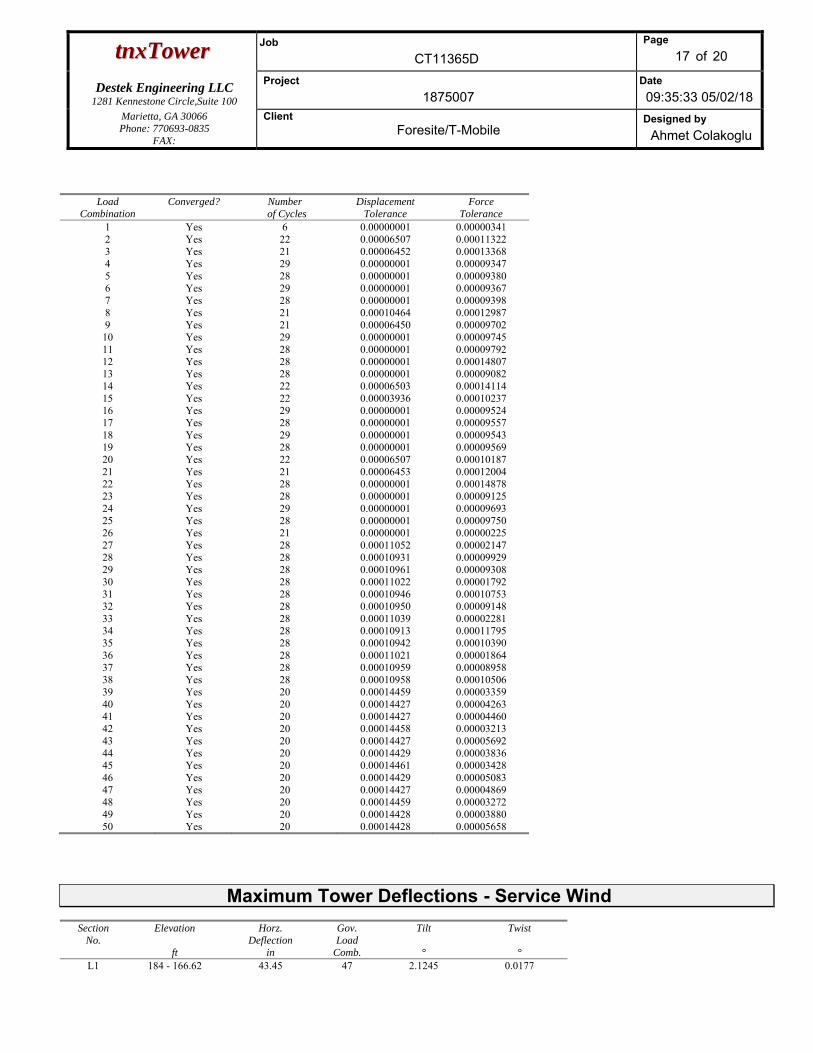
ttnnxxTToowweerr Job
CT11365D
Page
17 of 20
Destek Engineering LLC 1281 Kennestone Circle,Suite 100
Project
1875007 Date
09:35:33 05/02/18 Marietta, GA 30066 Phone: 770693-0835
FAX:
Client Foresite/T-Mobile
Designed by
Ahmet Colakoglu
Load Combination
Converged? Number of Cycles
Displacement Tolerance
Force Tolerance
1 Yes 6 0.00000001 0.000003412 Yes 22 0.00006507 0.000113223 Yes 21 0.00006452 0.000133684 Yes 29 0.00000001 0.000093475 Yes 28 0.00000001 0.000093806 Yes 29 0.00000001 0.000093677 Yes 28 0.00000001 0.000093988 Yes 21 0.00010464 0.000129879 Yes 21 0.00006450 0.0000970210 Yes 29 0.00000001 0.0000974511 Yes 28 0.00000001 0.0000979212 Yes 28 0.00000001 0.0001480713 Yes 28 0.00000001 0.0000908214 Yes 22 0.00006503 0.0001411415 Yes 22 0.00003936 0.0001023716 Yes 29 0.00000001 0.0000952417 Yes 28 0.00000001 0.0000955718 Yes 29 0.00000001 0.0000954319 Yes 28 0.00000001 0.0000956920 Yes 22 0.00006507 0.0001018721 Yes 21 0.00006453 0.0001200422 Yes 28 0.00000001 0.0001487823 Yes 28 0.00000001 0.0000912524 Yes 29 0.00000001 0.0000969325 Yes 28 0.00000001 0.0000975026 Yes 21 0.00000001 0.0000022527 Yes 28 0.00011052 0.0000214728 Yes 28 0.00010931 0.0000992929 Yes 28 0.00010961 0.0000930830 Yes 28 0.00011022 0.0000179231 Yes 28 0.00010946 0.0001075332 Yes 28 0.00010950 0.0000914833 Yes 28 0.00011039 0.0000228134 Yes 28 0.00010913 0.0001179535 Yes 28 0.00010942 0.0001039036 Yes 28 0.00011021 0.0000186437 Yes 28 0.00010959 0.0000895838 Yes 28 0.00010958 0.0001050639 Yes 20 0.00014459 0.0000335940 Yes 20 0.00014427 0.0000426341 Yes 20 0.00014427 0.0000446042 Yes 20 0.00014458 0.0000321343 Yes 20 0.00014427 0.0000569244 Yes 20 0.00014429 0.0000383645 Yes 20 0.00014461 0.0000342846 Yes 20 0.00014429 0.0000508347 Yes 20 0.00014427 0.0000486948 Yes 20 0.00014459 0.0000327249 Yes 20 0.00014428 0.0000388050 Yes 20 0.00014428 0.00005658
Maximum Tower Deflections - Service Wind
Section No.
Elevation
ft
Horz. Deflection
in
Gov. Load
Comb.
Tilt °
Twist °
L1 184 - 166.62 43.45 47 2.1245 0.0177
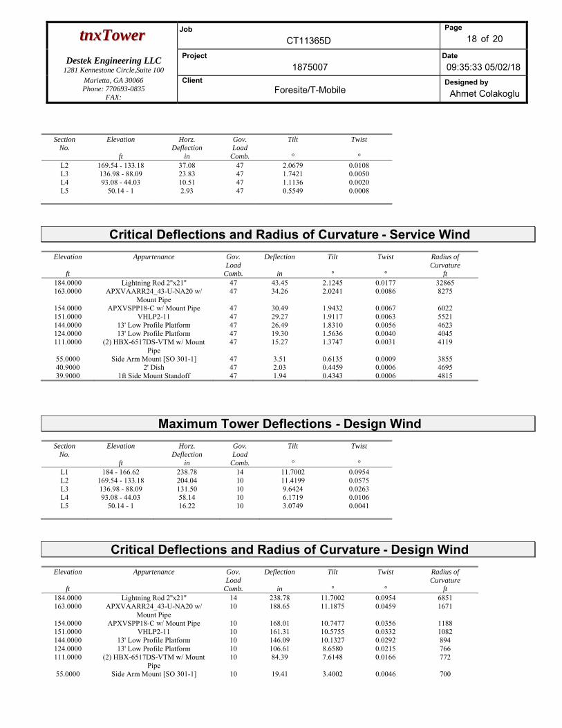
ttnnxxTToowweerr Job
CT11365D
Page
18 of 20
Destek Engineering LLC 1281 Kennestone Circle,Suite 100
Project
1875007 Date
09:35:33 05/02/18 Marietta, GA 30066 Phone: 770693-0835
FAX:
Client Foresite/T-Mobile
Designed by
Ahmet Colakoglu
Section No.
Elevation
ft
Horz. Deflection
in
Gov. Load
Comb.
Tilt °
Twist °
L2 169.54 - 133.18 37.08 47 2.0679 0.0108L3 136.98 - 88.09 23.83 47 1.7421 0.0050L4 93.08 - 44.03 10.51 47 1.1136 0.0020L5 50.14 - 1 2.93 47 0.5549 0.0008
Critical Deflections and Radius of Curvature - Service Wind
Elevation
ft
Appurtenance Gov. Load
Comb.
Deflection
in
Tilt °
Twist °
Radius of Curvature
ft 184.0000 Lightning Rod 2''x21'' 47 43.45 2.1245 0.0177 32865163.0000 APXVAARR24_43-U-NA20 w/
Mount Pipe 47 34.26 2.0241 0.0086 8275
154.0000 APXVSPP18-C w/ Mount Pipe 47 30.49 1.9432 0.0067 6022151.0000 VHLP2-11 47 29.27 1.9117 0.0063 5521144.0000 13' Low Profile Platform 47 26.49 1.8310 0.0056 4623124.0000 13' Low Profile Platform 47 19.30 1.5636 0.0040 4045111.0000 (2) HBX-6517DS-VTM w/ Mount
Pipe 47 15.27 1.3747 0.0031 4119
55.0000 Side Arm Mount [SO 301-1] 47 3.51 0.6135 0.0009 385540.9000 2' Dish 47 2.03 0.4459 0.0006 469539.9000 1ft Side Mount Standoff 47 1.94 0.4343 0.0006 4815
Maximum Tower Deflections - Design Wind
Section No.
Elevation
ft
Horz. Deflection
in
Gov. Load
Comb.
Tilt °
Twist °
L1 184 - 166.62 238.78 14 11.7002 0.0954L2 169.54 - 133.18 204.04 10 11.4199 0.0575L3 136.98 - 88.09 131.50 10 9.6424 0.0263L4 93.08 - 44.03 58.14 10 6.1719 0.0106L5 50.14 - 1 16.22 10 3.0749 0.0041
Critical Deflections and Radius of Curvature - Design Wind
Elevation
ft
Appurtenance Gov. Load
Comb.
Deflection
in
Tilt °
Twist °
Radius of Curvature
ft 184.0000 Lightning Rod 2''x21'' 14 238.78 11.7002 0.0954 6851163.0000 APXVAARR24_43-U-NA20 w/
Mount Pipe 10 188.65 11.1875 0.0459 1671
154.0000 APXVSPP18-C w/ Mount Pipe 10 168.01 10.7477 0.0356 1188151.0000 VHLP2-11 10 161.31 10.5755 0.0332 1082144.0000 13' Low Profile Platform 10 146.09 10.1327 0.0292 894 124.0000 13' Low Profile Platform 10 106.61 8.6580 0.0215 766 111.0000 (2) HBX-6517DS-VTM w/ Mount
Pipe 10 84.39 7.6148 0.0166 772
55.0000 Side Arm Mount [SO 301-1] 10 19.41 3.4002 0.0046 700
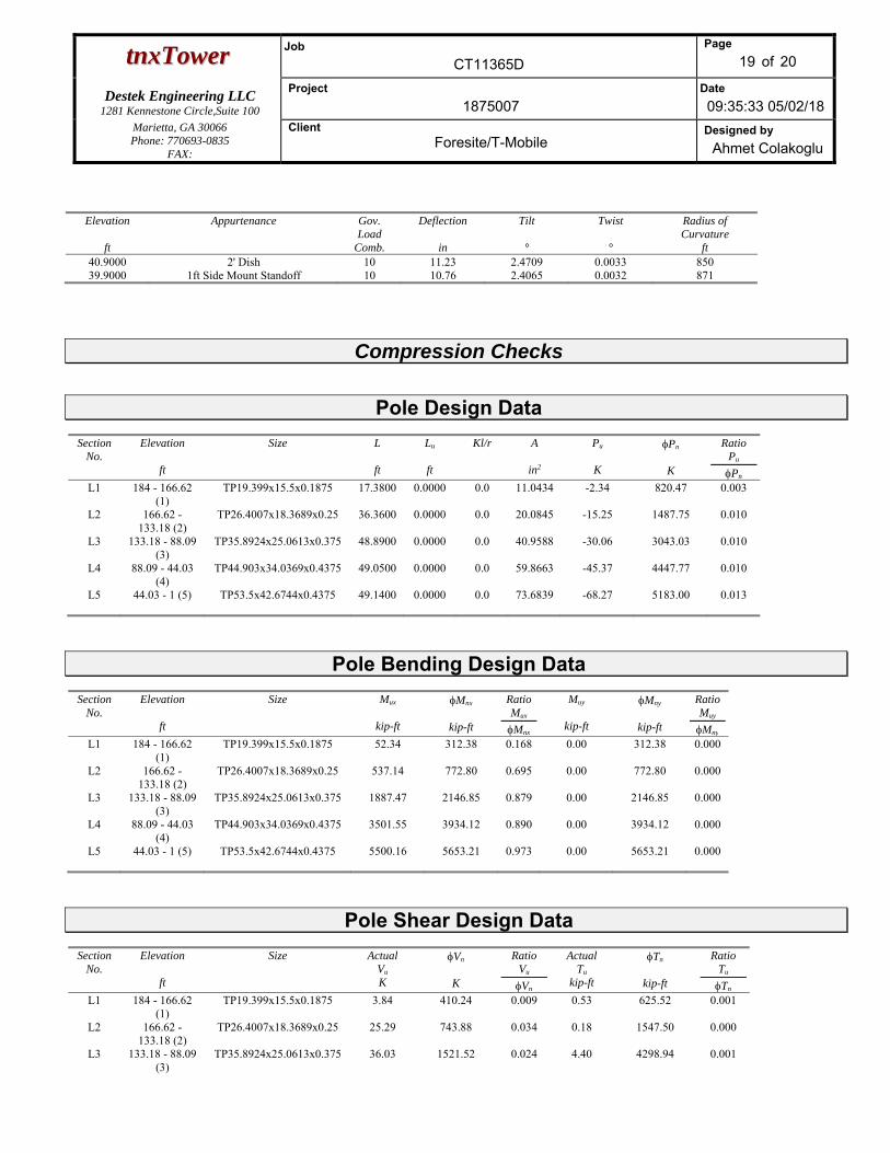
ttnnxxTToowweerr Job
CT11365D
Page
19 of 20
Destek Engineering LLC 1281 Kennestone Circle,Suite 100
Project
1875007 Date
09:35:33 05/02/18 Marietta, GA 30066 Phone: 770693-0835
FAX:
Client Foresite/T-Mobile
Designed by
Ahmet Colakoglu
Elevation
ft
Appurtenance Gov. Load
Comb.
Deflection
in
Tilt °
Twist °
Radius of Curvature
ft 40.9000 2' Dish 10 11.23 2.4709 0.0033 850 39.9000 1ft Side Mount Standoff 10 10.76 2.4065 0.0032 871
Compression Checks
Pole Design Data Section
No. Elevation
ft
Size
L
ft
Lu
ft
Kl/r
A
in2
Pu
K
Pn
K
Ratio Pu
Pn
L1 184 - 166.62 (1)
TP19.399x15.5x0.1875 17.3800 0.0000 0.0 11.0434 -2.34 820.47 0.003
L2 166.62 - 133.18 (2)
TP26.4007x18.3689x0.25 36.3600 0.0000 0.0 20.0845 -15.25 1487.75 0.010
L3 133.18 - 88.09 (3)
TP35.8924x25.0613x0.375 48.8900 0.0000 0.0 40.9588 -30.06 3043.03 0.010
L4 88.09 - 44.03 (4)
TP44.903x34.0369x0.4375 49.0500 0.0000 0.0 59.8663 -45.37 4447.77 0.010
L5 44.03 - 1 (5) TP53.5x42.6744x0.4375 49.1400 0.0000 0.0 73.6839 -68.27 5183.00 0.013
Pole Bending Design Data Section
No. Elevation
ft
Size
Mux
kip-ft
Mnx
kip-ft
Ratio Mux
Mnx
Muy
kip-ft
Mny
kip-ft
Ratio Muy
Mny
L1 184 - 166.62 (1)
TP19.399x15.5x0.1875 52.34 312.38 0.168 0.00 312.38 0.000
L2 166.62 - 133.18 (2)
TP26.4007x18.3689x0.25 537.14 772.80 0.695 0.00 772.80 0.000
L3 133.18 - 88.09 (3)
TP35.8924x25.0613x0.375 1887.47 2146.85 0.879 0.00 2146.85 0.000
L4 88.09 - 44.03 (4)
TP44.903x34.0369x0.4375 3501.55 3934.12 0.890 0.00 3934.12 0.000
L5 44.03 - 1 (5) TP53.5x42.6744x0.4375 5500.16 5653.21 0.973 0.00 5653.21 0.000
Pole Shear Design Data Section
No. Elevation
ft
Size
Actual Vu
K
Vn
K
Ratio Vu
Vn
Actual Tu
kip-ft
Tn
kip-ft
Ratio Tu
Tn
L1 184 - 166.62 (1)
TP19.399x15.5x0.1875 3.84 410.24 0.009 0.53 625.52 0.001
L2 166.62 - 133.18 (2)
TP26.4007x18.3689x0.25 25.29 743.88 0.034 0.18 1547.50 0.000
L3 133.18 - 88.09 (3)
TP35.8924x25.0613x0.375 36.03 1521.52 0.024 4.40 4298.94 0.001
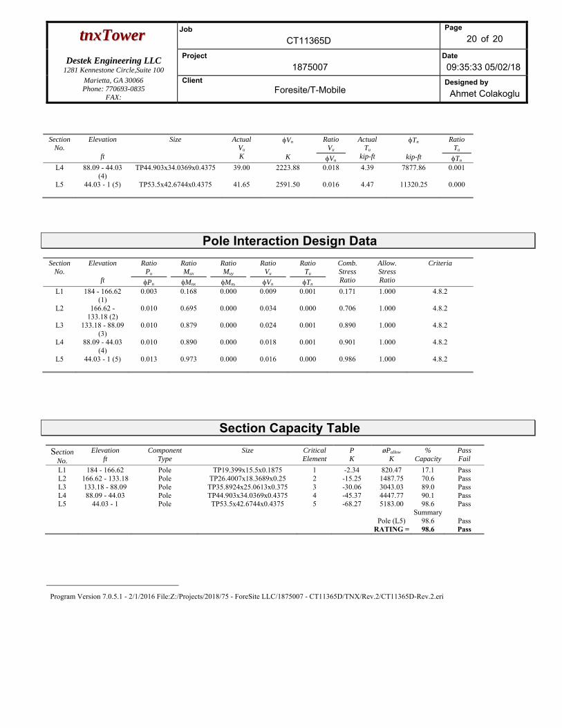
ttnnxxTToowweerr Job
CT11365D
Page
20 of 20
Destek Engineering LLC 1281 Kennestone Circle,Suite 100
Project
1875007 Date
09:35:33 05/02/18 Marietta, GA 30066 Phone: 770693-0835
FAX:
Client Foresite/T-Mobile
Designed by
Ahmet Colakoglu
Section No.
Elevation
ft
Size
Actual Vu
K
Vn
K
Ratio Vu
Vn
Actual Tu
kip-ft
Tn
kip-ft
Ratio Tu
Tn
L4 88.09 - 44.03 (4)
TP44.903x34.0369x0.4375 39.00 2223.88 0.018 4.39 7877.86 0.001
L5 44.03 - 1 (5) TP53.5x42.6744x0.4375 41.65 2591.50 0.016 4.47 11320.25 0.000
Pole Interaction Design Data Section
No. Elevation
ft
Ratio Pu
Pn
Ratio Mux
Mnx
Ratio Muy
Mny
Ratio Vu
Vn
Ratio Tu
Tn
Comb. Stress Ratio
Allow. Stress Ratio
Criteria
L1 184 - 166.62 (1)
0.003 0.168 0.000 0.009 0.001 0.171 1.000 4.8.2
L2 166.62 - 133.18 (2)
0.010 0.695 0.000 0.034 0.000 0.706 1.000 4.8.2
L3 133.18 - 88.09 (3)
0.010 0.879 0.000 0.024 0.001 0.890 1.000 4.8.2
L4 88.09 - 44.03 (4)
0.010 0.890 0.000 0.018 0.001 0.901 1.000 4.8.2
L5 44.03 - 1 (5) 0.013 0.973 0.000 0.016 0.000 0.986 1.000 4.8.2
Section Capacity Table
Section No.
Elevation ft
Component Type
Size CriticalElement
P K
øPallow
K %
Capacity Pass Fail
L1 184 - 166.62 Pole TP19.399x15.5x0.1875 1 -2.34 820.47 17.1 PassL2 166.62 - 133.18 Pole TP26.4007x18.3689x0.25 2 -15.25 1487.75 70.6 PassL3 133.18 - 88.09 Pole TP35.8924x25.0613x0.375 3 -30.06 3043.03 89.0 PassL4 88.09 - 44.03 Pole TP44.903x34.0369x0.4375 4 -45.37 4447.77 90.1 PassL5 44.03 - 1 Pole TP53.5x42.6744x0.4375 5 -68.27 5183.00 98.6 Pass
Summary Pole (L5) 98.6 Pass RATING = 98.6 Pass
Program Version 7.0.5.1 - 2/1/2016 File:Z:/Projects/2018/75 - ForeSite LLC/1875007 - CT11365D/TNX/Rev.2/CT11365D-Rev.2.eri
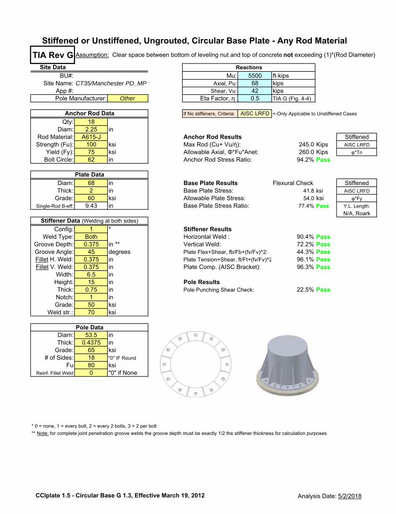
TIA Rev GSite Data
BU#: 5500 ft-kipsSite Name: 68 kips
App #: 42 kipsOther Eta Factor, η 0.5 TIA G (Fig. 4-4)
If No stiffeners, Criteria: AISC LRFD <-Only Applcable to Unstiffened Cases
Qty: 18Diam: 2.25 in
Rod Material: A615-J Anchor Rod Results StiffenedStrength (Fu): 100 ksi Max Rod (Cu+ Vu/ή): 245.0 Kips AISC LRFD
Yield (Fy): 75 ksi Allowable Axial, Φ*Fu*Anet: 260.0 Kips φ*Tn
Bolt Circle: 62 in Anchor Rod Stress Ratio: 94.2% Pass
Diam: 68 in Base Plate Results Flexural Check StiffenedThick: 2 in Base Plate Stress: 41.8 ksi AISC LRFD
Grade: 60 ksi Allowable Plate Stress: 54.0 ksi φ*Fy
Single-Rod B-eff: 9.43 in Base Plate Stress Ratio: 77.4% Pass Y.L. Length:
N/A, Roark
Config: 1 * Stiffener ResultsWeld Type: Both Horizontal Weld : 90.4% Pass
Groove Depth: 0.375 in ** Vertical Weld: 72.2% PassGroove Angle: 45 degrees Plate Flex+Shear, fb/Fb+(fv/Fv)^2: 44.3% PassFillet H. Weld: 0.375 in Plate Tension+Shear, ft/Ft+(fv/Fv)^2 96.1% PassFillet V. Weld: 0.375 in Plate Comp. (AISC Bracket): 96.3% Pass
Width: 6.5 inHeight: 15 in Pole ResultsThick: 0.75 in Pole Punching Shear Check: 22.5% PassNotch: 1 inGrade: 50 ksi
Weld str.: 70 ksi
Diam: 53.5 inThick: 0.4375 in
Grade: 65 ksi# of Sides: 18 "0" IF Round
Fu 80 ksiReinf. Fillet Weld 0 "0" if None
* 0 = none, 1 = every bolt, 2 = every 2 bolts, 3 = 2 per bolt
** Note: for complete joint penetration groove welds the groove depth must be exactly 1/2 the stiffener thickness for calculation purposes
Pole Manufacturer:
Assumption: Clear space between bottom of leveling nut and top of concrete not exceeding (1)*(Rod Diameter)
Stiffened or Unstiffened, Ungrouted, Circular Base Plate - Any Rod Material
Pole Data
Anchor Rod Data
Plate Data
Stiffener Data (Welding at both sides)
Reactions
Mu:Axial, Pu:
Shear, Vu:CT35/Manchester PD_MP
CCIplate 1.5 - Circular Base G 1.3, Effective March 19, 2012 Analysis Date: 5/2/2018
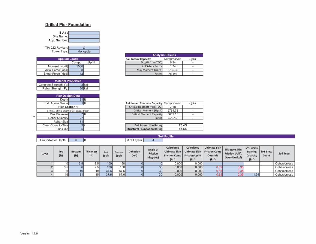
TIA-222 Revison: Check Pier Capacity only at location of Max Moment? NoTower Type:
Soil Lateral Capacity Compression UpliftComp. Uplift 6.94 -
5500 1.74 -68 5785.36 -42 76.4% -
Soil Vertical Capacity Compression Uplift159.61 -
3 ksi 44.45 -60 ksi 149.63 -
204.06 -217.63 -
31 ft 106.6% -1 ft Reinforced Concrete Capacity Compression Uplift
7.18 -5784.78 -
7 ft 6602.15 -27 87.6% -113 in5
6 ft # of Layers 4
FALSE 1 0 3.5 3.5 100 150 0 0 0.000 0.000FALSE 2 3.5 6 2.5 100 150 0 30 0.000 0.000 0.35 0.35FALSE 3 6 16 10 37.6 87.6 0 30 0.000 0.000 0.35 0.35FALSE 4 16 31 15 37.6 87.6 0 30 0.000 0.000 0.35 0.35 1.54
Moment (kip-ft)Axial Force (kips)
Shear Force (kips)
Concrete Strength, f'c:
Pier DiameterRebar Quantity
Rebar Strength, Fy:End Bearing (kips)
Total Capacity (kips)Axial (kips)
Dv=0 (ft from TOC)Soil Safety Factor
Max Moment (kip-ft)Rating
Skin Friction (kips)
Rebar SizeClear Cover to Ties
Tie Size
SPT Blow Count
Ult. Gross Bearing Capacity
(ksf)
γsoil
(pcf)γconcrete
(pcf)Cohesion
(ksf)
Angle of Friction
(degrees)
Calculated Ultimate Skin Friction Uplift
(ksf)
Calculated Ultimate Skin Friction Comp
(ksf)
LayerTop (ft)
Bottom (ft)
Thickness (ft)
Ultimate Skin Friction Comp
Override (ksf)
Ultimate Skin Friction Uplift Override (ksf)
Groundwater DepthSoil Profile
Soil Type
Rating
Weight of Concrete (kips)
DepthExt. Above Grade
Critical Depth (ft from TOC)Critical Moment (kip-ft)
Critical Moment CapacityRating
Pier Section 1From 1' above grade to 31' below grade
Analysis Results
Drilled Pier Foundation
BU # :Site Name:
App. Number:
Monopole
Applied Loads
Material Properties
Pier Design Data
G
76.4%87.6%
Soil Interaction RatingStructural Foundation Rating
Cohesionless
CohesionlessCohesionlessCohesionless
Version 1.1.0

Exhibit E
EBI Consulting environmental | engineering | due diligence
21 B Street . Burlington, MA 01803 . Tel: (781) 273.2500 . Fax: (781) 273.3311
RADIO FREQUENCY EMISSIONS ANALYSIS REPORT EVALUATION OF HUMAN EXPOSURE POTENTIAL
TO NON-IONIZING EMISSIONS
T-Mobile Existing Facility
Site ID: CT11365D
CT365/Manchester PD_MP 239 E. Middle Turnpike Manchester, CT 06040
May 22, 2018
EBI Project Number: 6218004013
Site Compliance Summary
Compliance Status: COMPLIANT
Site total MPE% of FCC general population
allowable limit:
14.684%
EBI Consulting environmental | engineering | due diligence
21 B Street . Burlington, MA 01803 . Tel: (781) 273.2500 . Fax: (781) 273.3311
May 22, 2018
T-Mobile USA
Attn: Jason Overbey, RF Manager
35 Griffin Road South
Bloomfield, CT 06002
Emissions Analysis for Site: CT11365D – CT365/Manchester PD_MP
EBI Consulting was directed to analyze the proposed T-Mobile facility located at 239 E. Middle
Turnpike, Manchester, CT, for the purpose of determining whether the emissions from the Proposed T-
Mobile Antenna Installation located on this property are within specified federal limits.
All information used in this report was analyzed as a percentage of current Maximum Permissible
Exposure (% MPE) as listed in the FCC OET Bulletin 65 Edition 97-01and ANSI/IEEE Std C95.1. The
FCC regulates Maximum Permissible Exposure in units of microwatts per square centimeter (W/cm2).
The number of W/cm2 calculated at each sample point is called the power density. The exposure limit
for power density varies depending upon the frequencies being utilized. Wireless Carriers and Paging
Services use different frequency bands each with different exposure limits, therefore it is necessary to
report results and limits in terms of percent MPE rather than power density.
All results were compared to the FCC (Federal Communications Commission) radio frequency exposure
rules, 47 CFR 1.1307(b)(1) – (b)(3), to determine compliance with the Maximum Permissible Exposure
(MPE) limits for General Population/Uncontrolled environments as defined below.
General population/uncontrolled exposure limits apply to situations in which the general population may
be exposed or in which persons who are exposed as a consequence of their employment may not be made
fully aware of the potential for exposure or cannot exercise control over their exposure. Therefore,
members of the general population would always be considered under this category when exposure is not
employment related, for example, in the case of a telecommunications tower that exposes persons in a
nearby residential area.
Public exposure to radio frequencies is regulated and enforced in units of microwatts per square
centimeter (μW/cm2). The general population exposure limits for the 600 MHz and 700 MHz Band are
approximately 400 μW/cm2 and 467 μW/cm2 respectively. The general population exposure limit for the
1900 MHz (PCS), 2100 MHz (AWS) and 5 GHz Microwave bands is 1000 μW/cm2. Because each carrier
will be using different frequency bands, and each frequency band has different exposure limits, it is
necessary to report percent of MPE rather than power density.
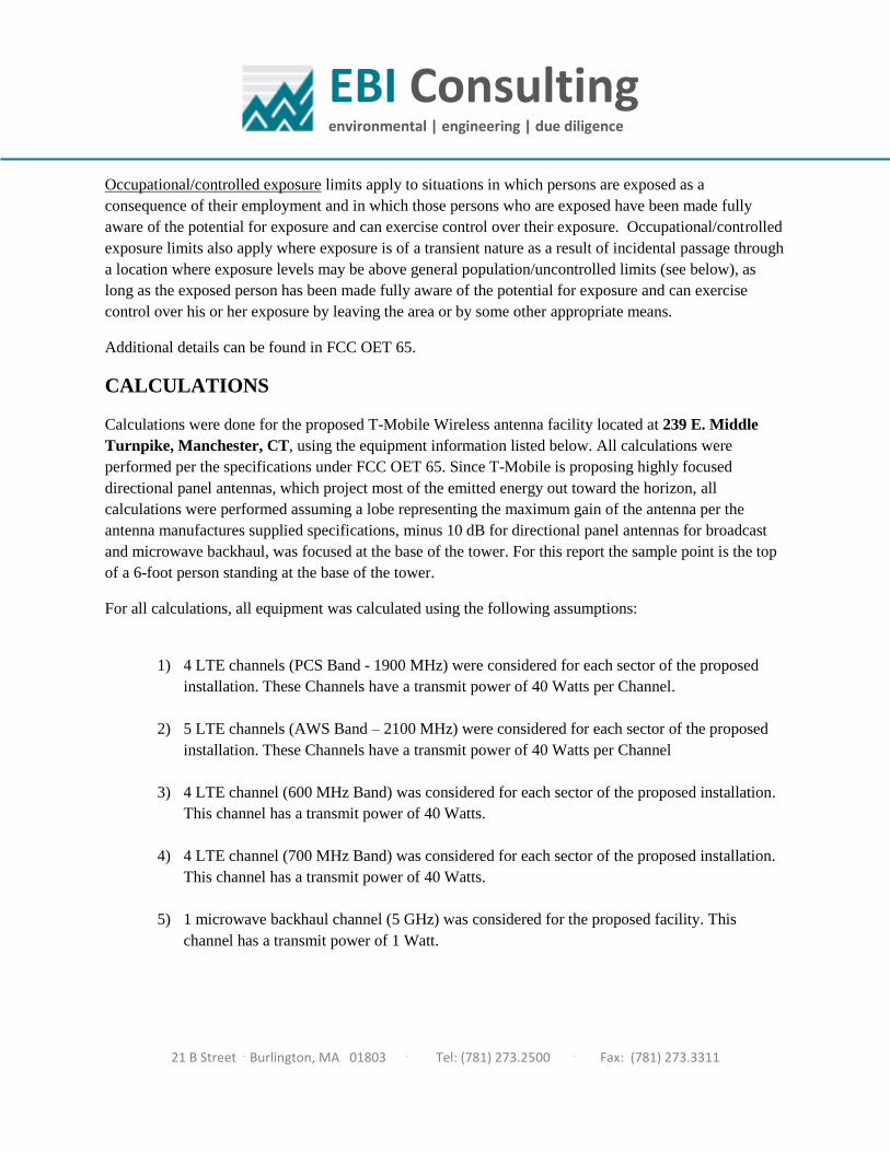
EBI Consulting environmental | engineering | due diligence
21 B Street . Burlington, MA 01803 . Tel: (781) 273.2500 . Fax: (781) 273.3311
Occupational/controlled exposure limits apply to situations in which persons are exposed as a
consequence of their employment and in which those persons who are exposed have been made fully
aware of the potential for exposure and can exercise control over their exposure. Occupational/controlled
exposure limits also apply where exposure is of a transient nature as a result of incidental passage through
a location where exposure levels may be above general population/uncontrolled limits (see below), as
long as the exposed person has been made fully aware of the potential for exposure and can exercise
control over his or her exposure by leaving the area or by some other appropriate means.
Additional details can be found in FCC OET 65.
CALCULATIONS
Calculations were done for the proposed T-Mobile Wireless antenna facility located at 239 E. Middle
Turnpike, Manchester, CT, using the equipment information listed below. All calculations were
performed per the specifications under FCC OET 65. Since T-Mobile is proposing highly focused
directional panel antennas, which project most of the emitted energy out toward the horizon, all
calculations were performed assuming a lobe representing the maximum gain of the antenna per the
antenna manufactures supplied specifications, minus 10 dB for directional panel antennas for broadcast
and microwave backhaul, was focused at the base of the tower. For this report the sample point is the top
of a 6-foot person standing at the base of the tower.
For all calculations, all equipment was calculated using the following assumptions:
1) 4 LTE channels (PCS Band - 1900 MHz) were considered for each sector of the proposed
installation. These Channels have a transmit power of 40 Watts per Channel.
2) 5 LTE channels (AWS Band – 2100 MHz) were considered for each sector of the proposed
installation. These Channels have a transmit power of 40 Watts per Channel
3) 4 LTE channel (600 MHz Band) was considered for each sector of the proposed installation.
This channel has a transmit power of 40 Watts.
4) 4 LTE channel (700 MHz Band) was considered for each sector of the proposed installation.
This channel has a transmit power of 40 Watts.
5) 1 microwave backhaul channel (5 GHz) was considered for the proposed facility. This
channel has a transmit power of 1 Watt.

EBI Consulting environmental | engineering | due diligence
21 B Street . Burlington, MA 01803 . Tel: (781) 273.2500 . Fax: (781) 273.3311
6) All radios at the proposed installation were considered to be running at full power and were
uncombined in their RF transmissions paths per carrier prescribed configuration. Per FCC
OET Bulletin No. 65 - Edition 97-01 recommendations to achieve the maximum anticipated
value at each sample point, all power levels emitting from the proposed antenna installation
are increased by a factor of 2.56 to account for possible in-phase reflections from the
surrounding environment. This is rarely the case, and if so, is never continuous.
7) For the following calculations the sample point was the top of a 6-foot person standing at the
base of the tower. The maximum gain of the antenna per the antenna manufactures supplied
specifications, minus 10 dB for directional panel antennas for broadcast and microwave
backhaul, was used in this direction. This value is a very conservative estimate as gain
reductions for these particular antennas are typically much higher in this direction.
8) The antennas used in this modeling are the Ericsson AIR32 B66A/B2A & Ericsson
AIR3246_B66 for 1900 MHz (PCS) and 2100 MHz (AWS) channels, the RFS
APXVAAR24-43-U-NA20 for 600 MHz and 700 MHz channels and the Fastback IBR1300
for the proposed 5 GHz microwave backhaul. This is based on feedback from the carrier with
regard to anticipated antenna selection. The Ericsson AIR32 B66A/B2A has a maximum
gain of 15.9 dBd at its main lobe at 1900 MHz and 2100 MHz. The Ericsson AIR3246_B66
has a maximum gain of 15.9 dBd at its main lobe at 1900 MHz and 2100 MHz. The RFS
APXVAAR24-43-U-NA20 has a maximum gain of 12.65/ 12.95 dBd at its main lobe at 600
MHz and 700 MHz respectively. The Fastback IBR1300 has a maximum gain of 10 dBd at
its main lobe at 5 GHz. The maximum gain of the antenna per the antenna manufactures
supplied specifications, minus 10 dB for directional panel antennas for broadcast and
microwave backhaul, was used for all calculations. This value is a very conservative estimate
as gain reductions for these particular antennas are typically much higher in this direction.
9) The antenna mounting height centerline of the proposed antennas (both panel antennas and
microwave antenna) is 163 feet above ground level (AGL).
10) Emissions values for additional carriers were taken from the Connecticut Siting Council
active database. Values in this database are provided by the individual carriers themselves.
11) All calculations were done with respect to uncontrolled / general population threshold limits.
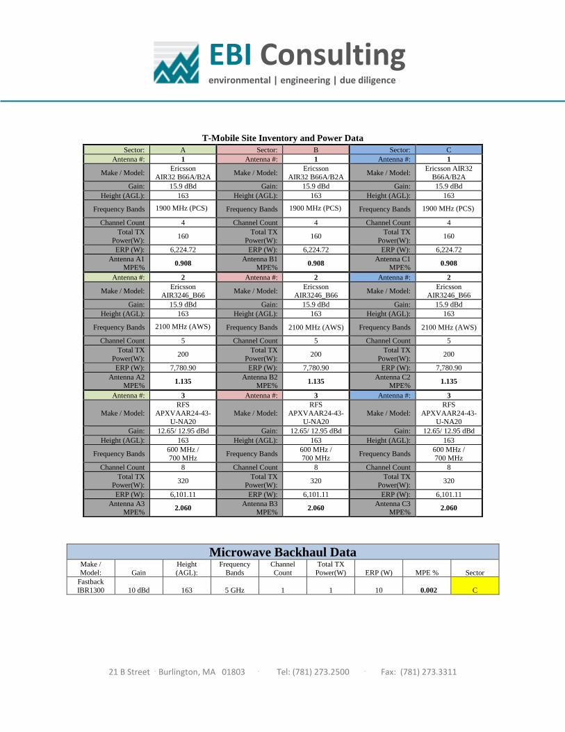
EBI Consulting environmental | engineering | due diligence
21 B Street . Burlington, MA 01803 . Tel: (781) 273.2500 . Fax: (781) 273.3311
T-Mobile Site Inventory and Power Data
Microwave Backhaul Data Make /
Model: Gain
Height
(AGL):
Frequency
Bands
Channel
Count
Total TX
Power(W) ERP (W) MPE % Sector
Fastback
IBR1300 10 dBd 163 5 GHz 1 1 10 0.002 C
Sector: A Sector: B Sector: C
Antenna #: 1 Antenna #: 1 Antenna #: 1
Make / Model: Ericsson
AIR32 B66A/B2A Make / Model:
Ericsson
AIR32 B66A/B2A Make / Model:
Ericsson AIR32
B66A/B2A
Gain: 15.9 dBd Gain: 15.9 dBd Gain: 15.9 dBd
Height (AGL): 163 Height (AGL): 163 Height (AGL): 163
Frequency Bands 1900 MHz (PCS) Frequency Bands 1900 MHz (PCS) Frequency Bands 1900 MHz (PCS)
Channel Count 4 Channel Count 4 Channel Count 4
Total TX
Power(W): 160
Total TX
Power(W): 160
Total TX
Power(W): 160
ERP (W): 6,224.72 ERP (W): 6,224.72 ERP (W): 6,224.72
Antenna A1 MPE%
0.908 Antenna B1
MPE% 0.908
Antenna C1 MPE%
0.908
Antenna #: 2 Antenna #: 2 Antenna #: 2
Make / Model: Ericsson
AIR3246_B66 Make / Model:
Ericsson AIR3246_B66
Make / Model: Ericsson
AIR3246_B66
Gain: 15.9 dBd Gain: 15.9 dBd Gain: 15.9 dBd
Height (AGL): 163 Height (AGL): 163 Height (AGL): 163
Frequency Bands 2100 MHz (AWS) Frequency Bands 2100 MHz (AWS) Frequency Bands 2100 MHz (AWS)
Channel Count 5 Channel Count 5 Channel Count 5
Total TX
Power(W): 200
Total TX
Power(W): 200
Total TX
Power(W): 200
ERP (W): 7,780.90 ERP (W): 7,780.90 ERP (W): 7,780.90
Antenna A2 MPE%
1.135 Antenna B2
MPE% 1.135
Antenna C2 MPE%
1.135
Antenna #: 3 Antenna #: 3 Antenna #: 3
Make / Model:
RFS
APXVAAR24-43-
U-NA20
Make / Model:
RFS
APXVAAR24-43-
U-NA20
Make / Model:
RFS
APXVAAR24-43-
U-NA20
Gain: 12.65/ 12.95 dBd Gain: 12.65/ 12.95 dBd Gain: 12.65/ 12.95 dBd
Height (AGL): 163 Height (AGL): 163 Height (AGL): 163
Frequency Bands 600 MHz /
700 MHz Frequency Bands
600 MHz /
700 MHz Frequency Bands
600 MHz /
700 MHz
Channel Count 8 Channel Count 8 Channel Count 8
Total TX Power(W):
320 Total TX
Power(W): 320
Total TX Power(W):
320
ERP (W): 6,101.11 ERP (W): 6,101.11 ERP (W): 6,101.11
Antenna A3 MPE%
2.060 Antenna B3
MPE% 2.060
Antenna C3 MPE%
2.060
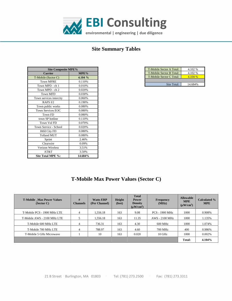
EBI Consulting environmental | engineering | due diligence
21 B Street . Burlington, MA 01803 . Tel: (781) 273.2500 . Fax: (781) 273.3311
Site Summary Tables
T-Mobile Max Power Values (Sector C)
T-Mobile Sector A Total: 4.102 %
T-Mobile Sector B Total: 4.102 %
T-Mobile Sector C Total: 4.104 %
Site Total: 14.684%
Site Composite MPE%
Carrier MPE%
T-Mobile (Sector C) 4.104 %
Town MFRE 0.110%
Town MPD - ch 1 0.010%
Town MPD - ch 2 0.020%
Town MFD 0.030%
Town services intercity 0.060%
RAFS I/2 0.190%
Town public works 0.080%
Town Services EOC 0.080%
Town FD 0.080%
town SP hotline 0.110%
Town Vol FD 0.070%
Town Service - School 0.020%
Htfd City FD 0.080%
Tolland MUT 0.080%
Sprint 2.46%
Clearwire 0.09%
Verizon Wireless 3.51%
AT&T 3.50%
Site Total MPE %: 14.684%
T-Mobile _Max Power Values
(Sector C)
#
Channels
Watts ERP
(Per Channel)
Height
(feet)
Total
Power
Density
(W/cm2)
Frequency
(MHz)
Allowable
MPE
(W/cm2)
Calculated %
MPE
T-Mobile PCS - 1900 MHz LTE 4 1,556.18 163 9.08 PCS - 1900 MHz 1000 0.908%
T-Mobile AWS - 2100 MHz LTE 5 1,556.18 163 11.35 AWS - 2100 MHz 1000 1.135%
T-Mobile 600 MHz LTE 4 736.31 163 4.30 600 MHz 1000 1.074%
T-Mobile 700 MHz LTE 4 788.97 163 4.60 700 MHz 400 0.986%
T-Mobile 5 GHz Microwave 1 10 163 0.020 10 GHz 1000 0.002%
Total: 4.104%
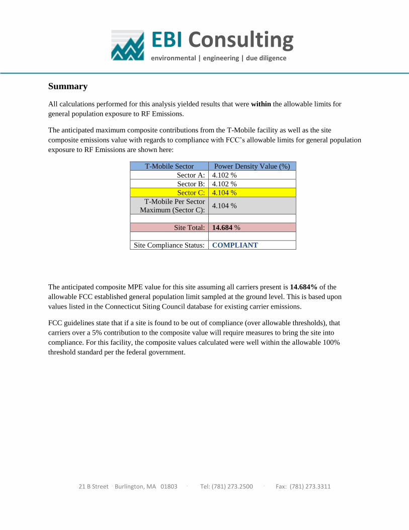
EBI Consulting environmental | engineering | due diligence
21 B Street . Burlington, MA 01803 . Tel: (781) 273.2500 . Fax: (781) 273.3311
Summary
All calculations performed for this analysis yielded results that were within the allowable limits for
general population exposure to RF Emissions.
The anticipated maximum composite contributions from the T-Mobile facility as well as the site
composite emissions value with regards to compliance with FCC’s allowable limits for general population
exposure to RF Emissions are shown here:
T-Mobile Sector Power Density Value (%)
Sector A: 4.102 %
Sector B: 4.102 %
Sector C: 4.104 %
T-Mobile Per Sector
Maximum (Sector C): 4.104 %
Site Total: 14.684 %
Site Compliance Status: COMPLIANT
The anticipated composite MPE value for this site assuming all carriers present is 14.684% of the
allowable FCC established general population limit sampled at the ground level. This is based upon
values listed in the Connecticut Siting Council database for existing carrier emissions.
FCC guidelines state that if a site is found to be out of compliance (over allowable thresholds), that
carriers over a 5% contribution to the composite value will require measures to bring the site into
compliance. For this facility, the composite values calculated were well within the allowable 100%
threshold standard per the federal government.

Exhibit F

P
Cut on dotted line.
Instructions
Click-N-Ship® Label Record
Electronic R
ate Approved #038555749
Thank you for shipping with the United States Postal Service!Check the status of your shipment on the USPS Tracking® page at usps.com
SH
IPTO
:
1. Each Click-N-Ship® label is unique. Labels are to be used as printed and used only once. DO NOT PHOTO COPY OR ALTER LABEL.
2. Place your label so it does not wrap around the edge of
the package. 3. Adhere your label to the package. A self-adhesive label
is recommended. If tape or glue is used, DO NOT TAPE OVER BARCODE. Be sure all edges are secure.
4. To mail your package with PC Postage®, you may schedule a Package Pickup online, hand to your letter carrier, take to a Post Office™, or drop in a USPS collection box. 5. Mail your package on the "Ship Date" you selected when creating this label.
Priority Mail® Postage:
From:
To:
Print Date:Ship Date:
Click-N
-Ship®
Trans. #:
Expected Delivery Date:
usps.com
US PO
STAG
E
* Retail Pricing Priority Mail rates apply. There is no fee for USPS Tracking® service on Priority Mail service with use of this electronic rate shipping label. Refunds for unused postage paid labels can be requested online 30 days from the print date.
Carrier -- Leave if N
o Response
Ref#: 3654X
2ZAP
USPS TR
AC
KIN
G #
$6.70
41 CE
NTE
R S
T
JAY
MO
RA
N
9405 5036 9930 0250 3766 71
DEBORAH CHASET-MOBILE USA- NSS35 GRIFFIN RD SBLOOMFIELD CT 06002-1351
9405 5036 9930 0250 3766 71 0067 0000 0010 6040
PRIO
RITY M
AIL 1-D
AY™C
004
9405 5036 9930 0250 3766 71
Mailed from
06002
Total437308562
Expected D
elivery Date: 06/16/18
0024
MA
NC
HE
STE
R C
T 06040-5090M
AY
OR
-TOW
N O
F MA
NC
HE
STE
R
Ref#: 3654X2ZAP
062S0000001311
06/15/2018
USPS TRACKING # :
06/14/2018
DE
BO
RA
H C
HA
SE
T-MO
BILE
US
A- N
SS
35 GR
IFFIN R
D S
BLO
OM
FIELD
CT 06002-1351
Flat Rate E
nv
06/15/2018
JAY MORANMAYOR-TOWN OF MANCHESTER41 CENTER STMANCHESTER CT 06040-5090
$6.70$6.70
06/16/2018
P
Cut on dotted line.
Instructions
Click-N-Ship® Label Record
Electronic R
ate Approved #038555749
Thank you for shipping with the United States Postal Service!Check the status of your shipment on the USPS Tracking® page at usps.com
SH
IPTO
:
1. Each Click-N-Ship® label is unique. Labels are to be used as printed and used only once. DO NOT PHOTO COPY OR ALTER LABEL.
2. Place your label so it does not wrap around the edge of
the package. 3. Adhere your label to the package. A self-adhesive label
is recommended. If tape or glue is used, DO NOT TAPE OVER BARCODE. Be sure all edges are secure.
4. To mail your package with PC Postage®, you may schedule a Package Pickup online, hand to your letter carrier, take to a Post Office™, or drop in a USPS collection box. 5. Mail your package on the "Ship Date" you selected when creating this label.
Priority Mail® Postage:
From:
To:
Print Date:Ship Date:
Click-N
-Ship®
Trans. #:
Expected Delivery Date:
usps.com
US PO
STAG
E
* Retail Pricing Priority Mail rates apply. There is no fee for USPS Tracking® service on Priority Mail service with use of this electronic rate shipping label. Refunds for unused postage paid labels can be requested online 30 days from the print date.
Carrier -- Leave if N
o Response
Ref#: 365-4X
2ZAP
USPS TR
AC
KIN
G #
$6.70
LINC
OLN
CE
NTE
R-2N
D FLO
OR
ZON
ING
DIR
EC
TOR
- TOW
N O
F MA
NC
HE
STE
R
9405 5036 9930 0250 3766 88
DEBORAH CHASET-MOBILE USA- NSS35 GRIFFIN RD SBLOOMFIELD CT 06002-1351
9405 5036 9930 0250 3766 88 0067 0000 0010 6040
PRIO
RITY M
AIL 1-D
AY™C
009
9405 5036 9930 0250 3766 88
Mailed from
06002
Total437308562
Expected D
elivery Date: 06/16/18
0024
MA
TTHE
W B
OR
DE
AU
MA
NC
HE
STE
R C
T 06040-4102494 M
AIN
ST
Ref#: 365-4X2ZAP
062S0000001311
06/15/2018
USPS TRACKING # :
06/14/2018
DE
BO
RA
H C
HA
SE
T-MO
BILE
US
A- N
SS
35 GR
IFFIN R
D S
BLO
OM
FIELD
CT 06002-1351
Flat Rate E
nv
06/15/2018
MATTHEW BORDEAUZONING DIRECTOR- TOWN OF MANCHESTER494 MAIN STLINCOLN CENTER-2ND FLOORMANCHESTER CT 06040-4102
$6.70$6.70
06/16/2018
P
Cut on dotted line.
Instructions
Click-N-Ship® Label Record
Electronic R
ate Approved #038555749
Thank you for shipping with the United States Postal Service!Check the status of your shipment on the USPS Tracking® page at usps.com
SH
IPTO
:
1. Each Click-N-Ship® label is unique. Labels are to be used as printed and used only once. DO NOT PHOTO COPY OR ALTER LABEL.
2. Place your label so it does not wrap around the edge of
the package. 3. Adhere your label to the package. A self-adhesive label
is recommended. If tape or glue is used, DO NOT TAPE OVER BARCODE. Be sure all edges are secure.
4. To mail your package with PC Postage®, you may schedule a Package Pickup online, hand to your letter carrier, take to a Post Office™, or drop in a USPS collection box. 5. Mail your package on the "Ship Date" you selected when creating this label.
Priority Mail® Postage:
From:
To:
Print Date:Ship Date:
Click-N
-Ship®
Trans. #:
Expected Delivery Date:
usps.com
US PO
STAG
E
* Retail Pricing Priority Mail rates apply. There is no fee for USPS Tracking® service on Priority Mail service with use of this electronic rate shipping label. Refunds for unused postage paid labels can be requested online 30 days from the print date.
Carrier -- Leave if N
o Response
USPS TR
AC
KIN
G #
$6.70
41 CE
NTE
R S
T
JOS
EP
H C
AM
PO
SE
O
9405 5036 9930 0250 3766 95
DEBORAH CHASET-MOBILE USA- NSS35 GRIFFIN RD SBLOOMFIELD CT 06002-1351
9405 5036 9930 0250 3766 95 0067 0000 0010 6040
PRIO
RITY M
AIL 1-D
AY™C
004
9405 5036 9930 0250 3766 95
Mailed from
06002
Total437308562
Expected D
elivery Date: 06/16/18
0024
MA
NC
HE
STE
R C
T 06040-5090TO
WN
CLE
RK
- TOW
N O
F MA
NC
HE
STE
R
062S0000001311
06/15/2018
USPS TRACKING # :
06/14/2018
DE
BO
RA
H C
HA
SE
T-MO
BILE
US
A- N
SS
35 GR
IFFIN R
D S
BLO
OM
FIELD
CT 06002-1351
Flat Rate E
nv
06/15/2018
JOSEPH CAMPOSEOTOWN CLERK- TOWN OF MANCHESTER41 CENTER STMANCHESTER CT 06040-5090
$6.70$6.70
06/16/2018