Embed Size (px)
Citation preview

414 IEEE TRANSACTIONS ON ELECTRON DEVICES, VOL. 62, NO. 2, FEBRUARY 2015
Vertical Power p-n Diodes Based on Bulk GaNIsik C. Kizilyalli, Fellow, IEEE, Andrew P. Edwards, Ozgur Aktas, Thomas Prunty,
and David Bour, Fellow, IEEE(Invited Paper)
Abstract— There is a great interest in wide-bandgapsemiconductor devices and most recently in monolithic GaNstructures for power electronics applications. In this paper,vertical p-n diodes fabricated on pseudobulk low defect density(104–106 cm−2) GaN substrates are discussed. Homoepitaxiallow-pressure metal organic chemical vapor deposition growthof GaN on its native substrate and being able to control andbalance the n-type Si doping with background C impurity hasallowed the realization of vertical device architectures withdrift layer thicknesses of 6 to 40 μm and net carrier electronconcentrations of 4 × 10¹⁵ to 2.5 × 1016 cm−3. This parameterrange is suitable for applications requiring breakdown voltages(BVs) of 600 V–4 kV with a proper edge termination strategy.Measured devices demonstrate near power device figure of merit,that is, differential specific on-resistance (Rsp) of 2 m�cm2 for aBV of 2.6 kV and 2.95 m�cm2 for a 3.7-kV device, respectively.The improvement in the substrate quality over the last fewyears has resulted in the fabrication of diodes with areas aslarge as 16 mm2, with BVs exceeding 700 V and pulsed (100 μs)currents of 400 A. The structures fabricated are utilized to studyin detail the temperature dependency of I–V characteristics,impact ionization and avalanche characteristics, and extract(estimate) modeling parameters such as electron mobility in theGaN c-direction (vertical) and hole minority carrier lifetimes.Some insight into device reliability is also provided.
Index Terms— Bulk GaN, electron mobility, p-n diode, verticalpower semiconductors.
I. INTRODUCTION
POWER electronics is the needed interface between anelectrical source and a load. The source and load can
differ in frequency, amplitude, number of phases, and voltagesand currents can be converted from one form to another [1].Some examples of a power electronic system are a laptopcharger converting 110 V ac power to 19 V dc power, a solarinverter converting 48 V dc power to 220 V ac power, an EVdrive using 200 V dc battery power to drive 650 V ac motor, athree-phase motor driver in hybrid vehicle, electric rail, ship,and so on. The building blocks comprising a power electronicssystem are power semiconductor devices, gate drivers, andcontroller circuits, as shown in Fig. 1. To date, the powersemiconductor components of this system have been wellserved by silicon based diodes and transistors (MOSFETs and
Manuscript received July 26, 2014; revised September 13, 2014; acceptedSeptember 19, 2014. Date of publication October 9, 2014; date of currentversion January 20, 2015. The review of this paper was arranged by EditorN. Ohtani.
The authors are with Avogy Inc., San Jose, CA 95134 USA(e-mail: [email protected]; [email protected]; [email protected];[email protected]; [email protected]).
Color versions of one or more of the figures in this paper are availableonline at http://ieeexplore.ieee.org.
Digital Object Identifier 10.1109/TED.2014.2360861
Fig. 1. Schematic demonstrating a power electronics system.
insulated-gate bipolar transistors). Tremendous improvementsin size, efficiency, weight, and power density of systemshas resulted from the improved performance of silicon-basedpower semiconductor devices. However, devices based onsilicon are rapidly approaching the fundamental material limitsof silicon. This has resulted in a rapid expansion of effortsto develop wide-bandgap power semiconductor alternativesutilizing SiC [2] and GaN [3]–[6], seeking further reduction insize and weight and increase in efficiency of power electronicsystems.
The interest in developing GaN-based power devicesis because the fundamental (material based) figure ofmerit (FOM) parameters for GaN are better than SiC andsignificantly better than Si. Some of the desirable propertiesassociated with GaN and its related alloys and heterostructuresinclude high bandgap energy and hence low intrinsic carrierconcentration (useful for high-temperature operation),favorable transport properties (large electron mobility andsaturation velocity), a high critical breakdown electric field,and high thermal conductivity [7]–[11]. SiC-based Schottkydiodes have already matured to a state of being commercial-ized and are commonly utilized in applications that demandhigher efficiency. However, the performance and reliability oflateral GaN-based devices has fallen short of their potentialbecause GaN layers grown on mismatched foreign substrates(e.g., Si or SiC) create difficulties for realizing vertical devicestructures and have higher defect densities (>108–109 cm−2).Low defect density is important in power devices because itcan affect the performance characteristics (e.g., breakdownvoltage and OFF-state leakage current), yield, and reliability[high temperature reverse bias (HRTB) and operating life,and avalanche ruggedness]. For GaN/InGaN lasers, notableimprovement in performance and reliability have been demon-strated using low defect density bulk GaN substrates [12], [13].It is generally recognized that lateral device architectures areless well suited to power applications, while vertical structuresare optimal for achieving higher breakdown voltage (BV)and current devices without paralleling (monolithic), suffer
0018-9383 © 2014 IEEE. Personal use is permitted, but republication/redistribution requires IEEE permission.See http://www.ieee.org/publications_standards/publications/rights/index.html for more information.

KIZILYALLI et al.: VERTICAL POWER p-n DIODES BASED ON BULK GaN 415
Fig. 2. Schematic of a vertical GaN p-n diode highlighting critical features.
less from thermal management issues associated with thinfilm surfaces, and yield more number of die on a wafer [14].The reason that there have been so few reports of verticalGaN power devices has been the lack of availability of lowdefect density (<106 cm−3) bulk GaN substrates. A relatedreason is the perception that bulk GaN substrates are tooexpensive to be commercially viable. However, there arealready multiple suppliers of bulk GaN substrates. Thematerial quality is improving rapidly due to research anddevelopment [15]–[17]. Moreover, the demand and scale ofthe optoelectronics industry is driving the prices down.
In this paper, GaN power diodes have been fabricatedby homoepitaxial growth on pseudobulk GaN substrates andthrough the development of process techniques applicable toedge termination of vertical structures. Near FOM perfor-mance devices are demonstrated for BVs from 600 V to 4 kV.The GaN p-n junction serves as a basic building block formost (if not all) high voltage (BV > 600 V) GaN verticaltransistors [18]–[22]. Furthermore, it is the ideal structure tostudy and extract preliminary information on substrate materialquality, doping, defects and generation–recombination rates,avalanche and impact ionization, critical electric field, ohmiccontacts, hole and electron mobility, minority carrier lifetimes,temperature effects, and reliability on an emerging materialsystem.
II. DEVICE DESIGN
The performance requirements for power semiconductordevices are low resistance for minimizing conduction losses,high breakdown (avalanche capability, especially important ininductive switching environments) voltage for the ability toblock large voltages, and low capacitance for fast switching(reduced switching losses). The unipolar power deviceFOM captures and formulates the conflicting requirementsbetween the device specific resistance (Rsp) versus the devicebreakdown voltage (BV) as BV2/Rsp ∼ μn EC
3, where μn isthe mobility for electrons and EC is the critical electric fieldat which breakdown occurs [23], [24]. The clear advantageof wide-bandgap semiconductor devices over silicon devicesarises from the cubed dependence of the FOM on the criticalelectric field. While the critical electric field for silicon is0.3 MV/cm, a value of at least 3.3 MV/cm for bulk GaN andpossibly as high as 3.75 MV/cm [25]–[28] has been suggested.
Fig. 2 shows a schematic of the GaN p-n diodes fabricatedand discussed here. Three regions of the device are of interest:
Fig. 3. Optimum design of GaN vertical device as guided by FOM.
1) the p-n junction (which forms the core of the device); 2) thelightly doped drift region; and 3) the edge termination/isolationregion.
High electron mobility at low doping levels in the driftregion allows the same region supporting high voltage inthe OFF-state to conduct current in the ON-state with asuperior tradeoff compared with other materials. In Fig. 3,the power device FOM is used to estimate the drift layerdoping, and thickness assuming an infinite planar junctionand an ideal edge termination, with EC = 3.3 MV/cm andμn = 1150 cm2/V·s. For example, to achieve a 5 kV devicewith the optimum ON-state conductance, the drift regionthickness needs to be about 35 μm and the net doping levelabout 5 × 1015 cm−3. While to design a device with a BVof 1200–1700 V, ideally a drift layer of 10 μm and a dopingof 1.5 × 1016 cm−3 are needed.
To take full advantage of the high critical electric field forthe onset of avalanche breakdown in GaN, it is essential tomanage the electric field at the edges (corner) of the device.An edge termination structure is used to spread the potentialapplied to the anode over a distance which is greater thanthe drift region thickness. This technique of smoothing theequipotential contours at the edges of the devices results in amanageable electric field (gradient of electrostatic potential).It should be noted that for each target BV, the edge terminationstructure needs to be custom designed. In all of the workpresented here, we use a version of junction terminationextension developed for vertical Si and SiC power devicesbut adapted for GaN using GaN specific processes [28]–[31].In any case, perfect geometric planes are impossible to achieveand a near ideal edge termination structure for GaN verticaldevices requires further development with the limitations tobe discussed later. We also recognize that the concept of acritical electric field in the context of nonstationary transportand the complicated nonisotropic band structure of GaN [25],[26], [32] is overly simplistic and is used here only to guidethe wafer experiments.
III. MATERIALS GROWTH AND DEVICE FABRICATION
Demand for bulk GaN substrates was initially driven bylaser diodes. Studies at Nichia and Sony established that the

416 IEEE TRANSACTIONS ON ELECTRON DEVICES, VOL. 62, NO. 2, FEBRUARY 2015
laser reliability was critically dependent on the threadingdislocation density (TDD) and that a TDD < 106 cm−2 wasrequired for long-lived lasers [12], [13]. This TDD is threeorders of magnitude lower than that of the GaN-on-sapphirefilms used for light-emitting diodes (LEDs), and could onlybe achieved by localized dislocation filtering techniques suchas epitaxial lateral overgrowth or with bulk GaN. However,it is exceedingly difficult to grow bulk-GaN crystals inthe traditional manner from a liquid melt, due to the veryhigh nitrogen pressure needed to stabilize the material.Instead, most commercial bulk GaN substrates are derivedfrom thick crystalline films, grown by hydride vapor phaseepitaxy on nonnative substrates, and subsequently removedfrom the substrate. The TDD of these wafers is typically106–107 cm−2 and sophisticated dislocation-getteringtechniques have been applied to reduce TDD to 104 cm−2
over a limited area (∼mm2). In the future, as the substratecost comes down, it is expected that bulk GaN substrates willbecome more widely adopted for large-area vertical devices,both electronic and optoelectronic. These benefits of lowercost and improved structural quality will accrue from theadvances in ammonothermal bulk growth [33].
The device structures were grown by low-pressure metalorganic chemical vapor deposition (MOCVD) on bulk GaNsubstrates. 0.5 μm p-type layers are doped with Mg, at aconcentration 2 × 1019 cm−3, and a higher doped layer atthe surface for reduced contact resistance. P-type materialhas been characterized by Hall measurements that indicate aroom-temperature hole concentration of 4 × 1017 cm−3 and amobility of 12 cm2/V·s. The net doping (ND–NA) determinesthe conductivity in forward bias and the depletion depth inreverse bias. Consequently, for kV-level operation net dopingcontrol in the n-type drift layer in the range of 1015–1016 cm−3
is crucial. During MOCVD growth of GaN, low-n-type-dopingis made difficult by contamination from carbon. Carbon isinherent in the MOCVD growth chemistry, supplied by theorganic gallium precursor, trimethylgallium Ga-(CH3)3. Sincecarbon assumes a deep-acceptor state in GaN, it compensatesintentional donors, typically Si (or Ge). During the MOCVDgrowth process, carbon background is minimized by the useof a hydride nitrogen precursor, ammonia (NH3), which yieldsboth chemically active nitrogen and hydrogen upon pyrolysis.The hydrogen liberated by ammonia pyrolysis eliminates themethyl radicals from the trimethylgallium in the form ofmethane that is stable and chemically inert in the process.Thereby, to the extent that this reaction is complete, thecarbon contamination is eliminated in MOCVD-grown GaNfilms. However, in practice, some residual carbon remains insmall concentration. This carbon background is minimizedby growing under conditions that represent a large partialpressure of active ammonia. These conditions may includecombination of high growth pressure, high growth temper-ature, and a high V:III ratio. Due to the chemical stabilityof ammonia, the V:III ratios used for GaN MOCVD growthare particularly high, typically greater than 1000. By growingunder optimal MOCVD conditions, the compensating carbonacceptor background may be reduced to 1015–1016 cm−3
range. Thus, the drift layer films are lightly n-type-doped
Fig. 4. Net doping and silicon concentration as a function of the silane flow.
and closely compensated with unintentional carbon, with netn-type doping of 5×10¹⁵–2×1016 cm−3. Here, we have usedsilane (diluted 100 ppm in nitrogen) for n-type doping.
At these low net-doping values, it is difficult to assessthe impurity concentrations in the traditional manner, bysecondary ion mass spectroscopy (SIMS). Rather, it ismost sensible to estimate the carbon concentration from itscompensation of the intentional and well-controlled silicondonors. This is so because the background concentrations ofsilicon, oxygen, and hydrogen in SIMS analysis are often inthe 1016 cm−3 range. This compensating effect is shown inFig. 4. This shows as a function of the silane doping flow,the silicon concentration measured by SIMS (solid circles),compared with the net doping (ND–NA) for two differentgrowth conditions (open circles and squares). At high siliconconcentrations, the silicon and net doping concentrationsare well matched. However, at low concentrations, the twocharacteristics deviate. The compensation from unintentionalcarbon acceptors is responsible for this deviation, whichreduces the net doping (ND–NA) from the Si (donor ND)concentration. From the characteristics in Fig. 4, we may inferthat for growth condition 1 (open circles), the concentration ofunintended carbon acceptors is approximately 5 × 1016 cm−3,while for improved growth condition 2 (open squares), theconcentration of unintended carbon acceptors is approximately1–2 × 1016 cm−3 (about 1 ppm).
Substrate orientation plays a significant role in the deviceperformance and reliability. A nominal c-orientation (0001),with slight inclination toward the m-plane is preferred, similarto the case for near-UV LEDs and laser diodes grown onbulk c-oriented-GaN substrates. For the case of on-axis growth(i.e., no misorientation), large hexagonal hillocks are naturallyformed during MOCVD growth, as shown in Fig. 5(a),a Nomarski micrograph image of hillocks formed by MOCVDepitaxial growth of GaN on an exact-(0001)-oriented bulkGaN substrate. These hillocks have been attributed to spiralgrowth around a screw dislocation [34], [35]. By introducinga slight miscut of several tenths of a degree, the surfaceis made vicinal, with step edge density proportional to themiscut angle. This increases the velocity of the step-flowgrowth, overwhelming the spiral growth and thereby producinga smooth surface.
KIZILYALLI et al.: VERTICAL POWER p-n DIODES BASED ON BULK GaN 417
Fig. 5. Nomarski image of (a) hillocks and (b) of surface morphologyobserved on devices grown on various GaN substrates. Devices in the toprow consistently have lower reverse currents at VR > 500 V and pass HTRBtests.
Fig. 6. CL images of GaN grown on (a) sapphire and (b) bulk GaN startingmaterial defect density of 104 cm−2. Note the scale change from (a) to (b).
Our p-n diode testing has revealed that the elimination ofthese hillocks and surface morphology [Fig. 5(b)] is mandatoryfor achieving low reverse leakage currents at voltages largerthan 500 V and passing HTRB reliability stress tests. Surfacepreparation and MOCVD epitaxial growth initiation are alsofound to be critical. Reliability and yield models based onaccurate spatial mapping of the surface morphology have beendeveloped and serve as an effective screen preprocessing andpostprocessing of devices.
The GaN layers comprising the vertical diodes in this paperwere epitaxially grown on full 2-inch bulk GaN substrateswith a defect density in the range of 104 to 3 × 106 cm−2.Plain-view cathode-luminescence (CL) imaging reveals thatthe TDD in the films grown over bulk GaN substrates is limitedby the defect density in the substrate and many orders ofmagnitude smaller compared with material grown on silicon,sapphire, or SiC substrates [Fig. 6(a) and (b)].
In the wafer process, the anode is formed by e-beamdeposition and patterning of Pd/Pt based metallization schemeto contact the p-type GaN. SiNx is used as passivationlayer. As discussed in Section II, an implant based junctiontermination extension scheme was utilized. The substrate wasthinned to 180 μm by backside grinding and polishing.Subsequently, a cathode electrode was formed. The thinningprocess is crucial in reducing the electrical and thermalresistance of the device. After on-wafer electrical screening,the devices were diced, and placed in standard power-packagesfor characterization.
Fig. 7. Measured forward I–V characteristics of a 1700 V optimizedp-n diode.
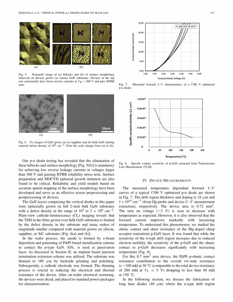
Fig. 8. Specific contact resistivity of p-GaN extracted from TransmissionLine Measurement (TLM).
IV. DEVICE MEASUREMENTS
The measured temperature dependent forward I–Vcurves of a typical 1700 V optimized p-n diode are shownin Fig. 7. The drift region thickness and doping is 18 μm and1×1016 cm−3 (from Hg-probe and device C–V measurementextraction), respectively. The device area is 0.72 mm2.The turn on voltage (∼3 V) is seen to decrease withtemperature as expected. However, it is also observed that theforward current improves markedly with increasingtemperature. To understand this phenomenon, we studied theohmic contact and sheet resistance of the Mg-doped (deepacceptor ionization) p-GaN layer. It was found that while theresistivity of the n-type drift region increases due to reducedelectron mobility, the resistivity of the p-GaN and the ohmiccontact to p-GaN decreases significantly with increasingtemperature (Fig. 8).
For this 0.7 mm2 area device, the Pd/Pt p-ohmic contactresistance contribution to the overall ON-state resistanceis ∼100 m� at 30 °C (comparable to the total device resistanceof 200 m� at VF = 5 V) dropping to less than 40 m�at 150 °C.
In the following section, we discuss the fabrication oflong base diodes (40 μm) where the n-type drift region

418 IEEE TRANSACTIONS ON ELECTRON DEVICES, VOL. 62, NO. 2, FEBRUARY 2015
Fig. 9. Current–voltage characteristics of a 40-μm n-type drift diode.
dominates the total resistance over the p-ohmic contact.These devices were fabricated with a net drift region dopingof 5 to 6×1015 cm−3 and edge termination suitable for achiev-ing BVs of 4 kV. The doping in the drift region was verifiedby C–V measurements on the device. The measured forwardI–V versus temperature is shown on a linear scale in Fig. 9.Temperature is swept from 25 °C to 150 °C in steps of 25 °C.This device was chosen as representative of a batch ofdozen fully characterized diodes. The turn on voltage isseen to decrease with temperature as expected, and in thiscase (contrary to the scenario above), the slope of the highcurrent region decreases. This indicates that the increasing theseries resistance in the n-type drift region is dominatingall other contributions. The active device area is235 μm × 470 μm = 0.11 mm2. The differential resistanceof the diode is about 2.25 �. The p-ohmic contribution isonly 0.35 �.
Fabrication of these diodes represents a unique opportunityto estimate the electron mobility in the low ionized impurityscattering limit and self-consistently extract hole minority car-rier lifetimes using TCAD models. This is because the forwardI–V curves are more dominated by the p-n junction and then-type drift region resistance and less by the contacts.
The forward current forward I–V –T is shown on a logscale in Fig. 10. At least, two slopes are apparent in thisp-n junction. Above 100 μA, the ideality factor isapproximately two, while at lower current levels, a highernonideality factor indicates that a more complicated modelfor recombination is appropriate. We will attempt to fit thesecurves across all temperature ranges but limit our interestto above 1 μA. In the TCAD model, a 2-D section withcylindrical symmetry about the center of the anode (resultingin an area equivalent to the measured device) was used.Sufficient lateral extent was included to account for the currentspreading occurring in the on-wafer device. The lateral extentused in the simulation was compared with an effectivelyinfinite extent, as available to the on-wafer diode to verify thatthere was no constraint due to the geometry. First, the effectof minority carrier lifetime on the low current region of thedevice was examined. Hole lifetime in the n-type drift regionstrongly influenced the forward current in this region. A value
Fig. 10. Current–voltage–temperature characteristics on a logarithmic scale.
Fig. 11. Current–voltage fits with varying hole minority carrier lifetime tothe measured characteristics of a 40-μm n-type drift diode at 25 °C.
Fig. 12. Current–voltage simulation versus measurement at 150 °C.
for τh of 2 ns provided the best fit to the measured data at25 °C as well as 150 °C. The 25 °C and 150 °C measureddata and simulation is shown in Figs. 11 and 12. τh of 0.1 ns
KIZILYALLI et al.: VERTICAL POWER p-n DIODES BASED ON BULK GaN 419
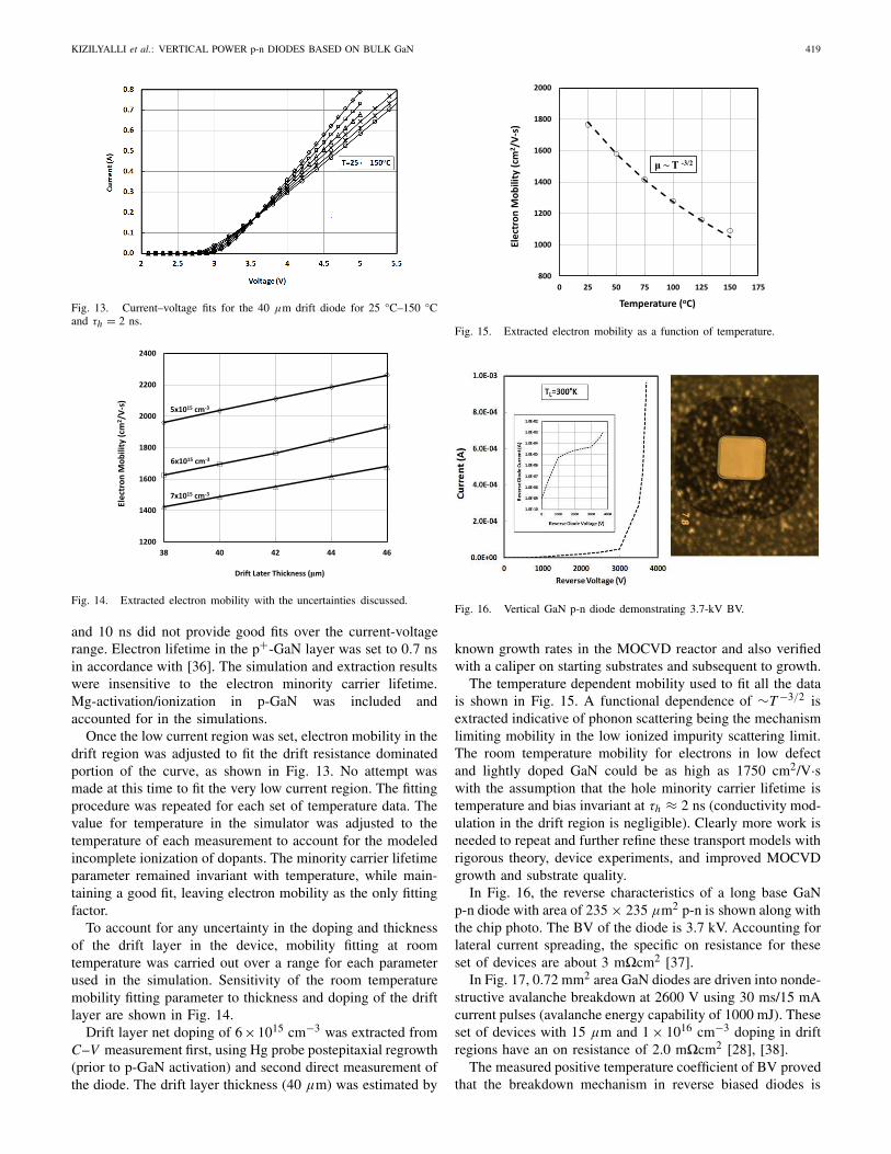
Fig. 13. Current–voltage fits for the 40 μm drift diode for 25 °C–150 °Cand τh = 2 ns.
Fig. 14. Extracted electron mobility with the uncertainties discussed.
and 10 ns did not provide good fits over the current-voltagerange. Electron lifetime in the p+-GaN layer was set to 0.7 nsin accordance with [36]. The simulation and extraction resultswere insensitive to the electron minority carrier lifetime.Mg-activation/ionization in p-GaN was included andaccounted for in the simulations.
Once the low current region was set, electron mobility in thedrift region was adjusted to fit the drift resistance dominatedportion of the curve, as shown in Fig. 13. No attempt wasmade at this time to fit the very low current region. The fittingprocedure was repeated for each set of temperature data. Thevalue for temperature in the simulator was adjusted to thetemperature of each measurement to account for the modeledincomplete ionization of dopants. The minority carrier lifetimeparameter remained invariant with temperature, while main-taining a good fit, leaving electron mobility as the only fittingfactor.
To account for any uncertainty in the doping and thicknessof the drift layer in the device, mobility fitting at roomtemperature was carried out over a range for each parameterused in the simulation. Sensitivity of the room temperaturemobility fitting parameter to thickness and doping of the driftlayer are shown in Fig. 14.
Drift layer net doping of 6×1015 cm−3 was extracted fromC–V measurement first, using Hg probe postepitaxial regrowth(prior to p-GaN activation) and second direct measurement ofthe diode. The drift layer thickness (40 μm) was estimated by
Fig. 15. Extracted electron mobility as a function of temperature.
Fig. 16. Vertical GaN p-n diode demonstrating 3.7-kV BV.
known growth rates in the MOCVD reactor and also verifiedwith a caliper on starting substrates and subsequent to growth.
The temperature dependent mobility used to fit all the datais shown in Fig. 15. A functional dependence of ∼T −3/2 isextracted indicative of phonon scattering being the mechanismlimiting mobility in the low ionized impurity scattering limit.The room temperature mobility for electrons in low defectand lightly doped GaN could be as high as 1750 cm2/V·swith the assumption that the hole minority carrier lifetime istemperature and bias invariant at τh ≈ 2 ns (conductivity mod-ulation in the drift region is negligible). Clearly more work isneeded to repeat and further refine these transport models withrigorous theory, device experiments, and improved MOCVDgrowth and substrate quality.
In Fig. 16, the reverse characteristics of a long base GaNp-n diode with area of 235 × 235 μm2 p-n is shown along withthe chip photo. The BV of the diode is 3.7 kV. Accounting forlateral current spreading, the specific on resistance for theseset of devices are about 3 m�cm2 [37].
In Fig. 17, 0.72 mm2 area GaN diodes are driven into nonde-structive avalanche breakdown at 2600 V using 30 ms/15 mAcurrent pulses (avalanche energy capability of 1000 mJ). Theseset of devices with 15 μm and 1 × 1016 cm−3 doping in driftregions have an on resistance of 2.0 m�cm2 [28], [38].
The measured positive temperature coefficient of BV provedthat the breakdown mechanism in reverse biased diodes is

420 IEEE TRANSACTIONS ON ELECTRON DEVICES, VOL. 62, NO. 2, FEBRUARY 2015
Fig. 17. GaN diode demonstrating 2.6 kV BV and 2.0 m�-cm2.
Fig. 18. Temperature dependence of BV in GaN p-n diode.
Fig. 19. Temperature dependence of reverse leakage current in GaNp-n diode.
due to impact ionization initiated avalanche [28], [38].Along with figures therein, Fig. 18 confirms that increasingthe temperature delays the onset of impact ionizationdue to phonon scattering. The temperature dependence ofbreakdown voltage is BV(T ) ≈ BV25 °C(1 + α�T ), whereα ≈ 6 × 10⁻⁴ °K−1. We found this to be roughly valid forall diodes we fabricated with BVs between 600–2500 V. Fullband-structure Monte Carlo theory predicts this coefficientas α ≈ 5.8 × 10⁻⁴ °K−1 [39]. The physics behind thisphenomenon will be explored in another publication andshould provide insight into the electron transport at highelectric fields in low defect density GaN.
While impact ionization has a positive temperature coef-ficient, Shockley–Read–Hall recombination current increasesin reverse biased junction with temperature. In Fig. 19, the
Fig. 20. Two-inch GaN wafer with 1–16 mm2 diodes and the 400 A pulsedI–V .
Fig. 21. FOM curve and Avogy fabricated vertical GaN p-n diodes.
temperature dependence (30 °C to 150 °C) of a typical0.72 mm2 1200 V diode is given for completeness.
In order for GaN devices to be competitive with theirsilicon and SiC counterparts for power electronic applications,current levels need to exceed 10 A and reach to 100 A. To thisend, we have fabricated large area (16 mm2) vertical GaNp-n diodes with BVs exceeding 700 V and pulsed (100 μs)currents of 400 A (2.5 kA/cm2) [40] (Fig. 20). These setof devices were fabricated using substrates with a defectdensity of about 3×106 cm−2 and the reverse leakage currentwas not measurably higher (or BVs lower) than devicesfabricated on substrates with defect densities of 104 cm−2
and the reverse leakage yield on the 16 mm2 die was higherthan 40%. Recently, we have fabricated 16 mm2 diodes with1200 V reverse leakage (<1 μA) yields approaching 70%.
However, in reliability studies, and in high temperatureoperating life (forward current stress with 150 °C junction)tests in particular, we find that the devices fabricated on lowerdefect density substrates fare much better. Other factors seemto be more important for HRTB tests (reverse bias stress at960 V and 125 °C–175 °C). Avogy diodes routinely passHTRB stress tests. In Fig. 21, Avogy diodes are placed onthe FOM plot.
V. CONCLUSION
In this paper, vertical p-n diodes fabricated on pseudobulklow defect density (104–3 × 106 cm−2) GaN substrates werediscussed. The p-n junction is the basic building block of mostvertical power devices, so its study is critical [28], [37]–[42].

KIZILYALLI et al.: VERTICAL POWER p-n DIODES BASED ON BULK GaN 421
We also presented in detail the temperature dependencyof I–V characteristics, BV, and extracted modeling parameterssuch as electron mobility and minority carrier lifetimes. Futurework will focus on elucidating reliability and substrate/defecteffects, and applying advanced materials and electricalcharacterization to study devices on bulk GaN.
ACKNOWLEDGMENT
The authors would like to thank M. Raj, D. Disney,H. Nie, B. Kayes, B. Alvarez, S. Nafis, G. Ye, R. Orr, andP. Bui-Quang, for the significant contributions and the staff ofAvogy Wafer Fab Facility.
REFERENCES
[1] N. Mohan, Power Electronic: A First Course. New York, NY, USA:Wiley, 2012.
[2] J. W. Palmour, J. Q. Zhang, M. K. Das, R. Callanan, A. K. Agarwal,and D. E. Grider, “SiC powes systems,” in Proc. Int. Power Electron.Conf., Jun. 2010, pp. 1006–1013.
[3] J. W. Johnson et al., “Breakdown voltage and reverse recovery charac-teristics of free-standing GaN Schottky rectifiers,” IEEE Trans. ElectronDevices, vol. 49, no. 1, pp. 32–36, Jan. 2002.
[4] Y. Uemoto et al., “8300 V blocking voltage AlGaN/GaN power HFETwith thick poly-AlN passivation,” in IEEE IEDM Tech. Dig., Dec. 2007,pp. 861–864.
[5] Y. Dora, A. Chakraborty, L. McCarthy, S. Keller, S. P. DenBaars, andU. K. Mishra, “High breakdown voltage achieved on AlGaN/GaNHEMTs with integrated slant field plates,” IEEE Electron Device Lett.,vol. 27, no. 9, pp. 713–715, Sep. 2006.
[6] B. Lu and T. Palacios, “High breakdown (>1500 V) AlGaN/GaNHEMTs by substrate transfer technology,” IEEE Electron Device Lett.,vol. 31, no. 9, pp. 951–953, Sep. 2010.
[7] J. D. Albrecht, R. P. Wang, P. P. Ruden, M. Farahmand, andK. F. Brennan, “Electron transport characteristics of GaN for hightemperature device modeling,” J. Appl. Phys., vol. 83, no. 9,pp. 4777–4781, 1998.
[8] C. Koughia, Springer Handbook of Electronic and Photonic Materials,S. Kasap and P. Capper, Eds. New York, NY, USA: Springer-Verlag,2006.
[9] T. P. Chow, “GaN power devices,” in Proc. Int. Symp. Power Semicond.Devices ICs, Short Course, 2008, pp. 159–186.
[10] R. Quay, Gallium Nitride Electronics. New York, NY, USA:Springer-Verlag, 2008.
[11] C. Mion, J. F. Muth, E. A. Preble, and D. Hanser, “Accurate dependenceof gallium nitride thermal conductivity on dislocation density,” Appl.Phys. Lett., vol. 89, no. 9, pp. 092123-1–092123-3, 2006.
[12] S. Nakamura et al., “High-power, long-lifetime InGaN/GaN/AlGaN-based laser diodes grown on pure GaN substrates,” Jpn. J. Appl. Phys.,vol. 37, no. 3B, pp. L309–L312, 1998.
[13] S. Tomiya, T. Hino, S. Goto, M. Takeya, and M. Ikeda, “Dislocationrelated issues in the degradation of GaN-based laser diodes,” IEEEJ. Sel. Topics Quantum Electron., vol. 10, no. 6, pp. 1277–1286,Nov./Dec. 2004.
[14] H. Ueda, M. Sugimoto, T. Uesugi, and T. Kachi, “Wide band-gapsemiconductors for automobile applications,” in CS MANTECH Conf.Dig., 2006, pp. 37–40.
[15] K. Motoki, “Development of gallium nitride substrates,” SEI Tech. Rev.,no. 70, pp. 28–35, 2010.
[16] D. Ehrentraut, E. Meissner, and M. Bockowski, Eds., Technology ofGallium Nitride Crystal Growth. New York, NY, USA: Springer-Verlag,2001.
[17] Y. Otoki et al., “Impact of crystal-quality improvement of epitaxialwafers on RF and power switching devices by utilizing VAS-methodgrown GaN substrates with low-density and uniformly distributed dis-locations,” in CS MANTECH Conf. Dig., 2013, pp. 109–112.
[18] M. Kanechika et al., “A vertical insulated gate AlGaN/GaN hetero-junction field-effect transistor,” Jpn. J. Appl. Phys., vol. 46, no. 21,pp. L503–L505, 2007.
[19] H. Otake, K. Chikamatsu, A. Yamaguchi, T. Fujishima, and H. Ohta,“Vertical GaN-based trench gate metal oxide semiconductor field-effecttransistors on GaN bulk substrates,” Appl. Phys. Exp., vol. 1, no. 1,pp. 011105-1–011105-3, 2008.
[20] T. Oka, Y. Ueno, T. Ina, and K. Hasegawa, “Vertical GaN-based trenchmetal oxide semiconductor field-effect transistors on a free-standingGaN substrate with blocking voltage of 1.6 kV,” Appl. Phys. Exp., vol. 7,no. 2, p. 021002, 2014.
[21] S. Chowdhury, M. Hoi Wong, B. L. Swenson, and U. K. Mishra,“CAVET on bulk GaN substrates achieved with MBE-regrownAlGaN/GaN layers to suppress dispersion,” IEEE Electron Device Lett.,vol. 33, no. 1, pp. 41–43, Jan. 2012.
[22] H. Nie et al., “1.5-kV and 2.2-m�-cm2 vertical GaN transistors on bulk-GaN substrates,” IEEE Electron Device Lett., vol. 35, no. 9, pp. 939–941,Sep. 2014.
[23] K. Shenai, R. S. Scott, and B. J. Baliga, “Optimum semiconductors forhigh-power electronics,” IEEE Trans. Electron Devices, vol. 36, no. 9,pp. 1811–1823, Sep. 1989.
[24] B. J. Baliga, Fundamentals of Power Semiconductor Devices. New York,NY, USA: Springer-Verlag, 2008.
[25] I. H. Oguzman, E. Bellotti, K. F. Brennan, J. Kolník, R. Wang, andP. P. Ruden, “Theory of hole initiated impact ionization in bulkzincblende and wurtzite GaN,” J. Appl. Phys., vol. 81, no. 12,pp. 7827–7834, 1997.
[26] S. Sridharan, P. D. Yoder, S. C. Shen, J. H. Ryou, and R. D. Dupuis,“Geiger mode simulation of GaN homojunction avalanche photodetec-tors,” Phys. Status Solidi C, vol. 6, pp. S662–S665, Jun. 2009.
[27] A. M. Ozbek and B. J. Baliga, “Planar nearly ideal edge-terminationtechnique for GaN devices,” IEEE Electron Device Lett., vol. 32, no. 3,pp. 300–302, Mar. 2011.
[28] I. C. Kizilyalli, A. P. Edwards, H. Nie, D. Disney, and D. Bour, “Highvoltage vertical GaN p-n diodes with avalanche capability,” IEEE Trans.Electron Devices, vol. 60, no. 10, pp. 3067–3070, Oct. 2013.
[29] J. R. Laroche, F. Ren, K. W. Baik, S. J. Pearton, B. S. Shelton, andB. Peres, “Design of edge termination for GaN power Schottky diodes,”J. Electrochem. Mater., vol. 34, no. 4, pp. 370–374, 2005.
[30] A. V. Bolotnikov, P. G. Muzykov, Q. Zhang, A. K. Agarwal, andT. S. Sudarshan, “Junction termination extension implementing drive-indiffusion of boron for high-voltage SiC devices,” IEEE Trans. ElectronDevices, vol. 57, no. 8, pp. 1930–1935, Aug. 2007.
[31] U.S. Patents 8 741 707, 8 716 716, 8 592 298, May 6, 2014.[32] S. Sridharan, A. Christensen, A. Venkatachalam, S. Graham, and
P. D. Yoder, “Temperature- and doping-dependent anisotropic stationaryelectron velocity in wurtzite GaN,” IEEE Electron Device Lett., vol. 32,no. 11, pp. 1522–1524, Nov. 2011.
[33] D. Ehrentraut, E. Meissner, and M. Bockowski, Eds., Technology ofGallium Nitride Crystal Growth. New York, NY, USA: Springer-Verlag,2010.
[34] R. M. Farrell, E. C. Young, F. Wu, S. P. DenBaars, and J. S. Speck,“Materials and growth issues for high-performance nonpolar and semi-polar light-emitting devices,” Semicond. Sci. Technol., vol. 27, no. 2,p. 024001, 2012.
[35] F. Oehler, T. Zhu, S. Rhode, M. J. Kappers, C. J. Humphreys, andR. A. Oliver, “Surface morphology of homoepitaxial c-plane GaN:Hillocks and ridges,” J. Crystal Growth, vol. 383, pp. 12–18,Nov. 2013.
[36] K. Kumakura, T. Makimoto, N. Kobayashi, T. Hashizume, T. Fukui,and H. Hasegawa, “Minority carrier diffusion length in GaN: Dislocationdensity and doping concentration dependence,” Appl. Phys. Lett., vol. 86,no. 5, pp. 052105-1–052105-3, 2005.
[37] I. C. Kizilyalli, A. P. Edwards, H. Hie, D. Bour, T. Prunty, and D. Disney,“3.7 kV vertical GaN PN diodes,” IEEE Electron Device Lett., vol. 35,no. 2, pp. 247–249, Feb. 2014.
[38] D. Disney, H. Nie, A. Edwards, D. Bour, H. Shah, and I. C. Kizilyalli,“Vertical power diodes in bulk GaN,” in Proc. 25th Int. Symp. PowerSemicond. Devices ICs (ISPSD), Kanazawa, Japan, 2013, pp. 59–62.
[39] D. Yoder, private communication, Jul. 2013.[40] I. C. Kizilyalli, A. P. Edwards, H. Nie, P. Bui-Quang, D. Disney, and
D. Bour, “400-A (pulsed) vertical GaN p-n diode with breakdownvoltage of 700 V,” IEEE Electron Device Lett., vol. 35, no. 6,pp. 654–656, Jun. 2014.
[41] Y. Hatakeyama, K. Nomoto, N. Kaneda, T. Kawano, T. Mishima, andT. Nakamura, “Over 3.0 GW/cm2 figure-of-merit GaN p-n junctiondiodes on free-standing GaN substrates,” IEEE Electron Device Lett.,vol. 32, no. 12, pp. 1674–1676, Dec. 2011.
[42] Y. Saitoh et al., “Extremely low on-resistance and high breakdownvoltage observed in vertical GaN Schottky barrier diodes with high-mobility drift layers on low-dislocation-density GaN substrates,” Appl.Phys. Exp., vol. 3, no. 8, p. 081001, 2010.

422 IEEE TRANSACTIONS ON ELECTRON DEVICES, VOL. 62, NO. 2, FEBRUARY 2015
Isik C. Kizilyalli (M’84–SM’94–F’07) received theB.S., M.S., and Ph.D. degrees from the Universityof Illinois at Urbana-Champaign, Champaign, IL,USA.
He has held positions at Bell Laboratories, MurrayHill, NJ, USA, Agere Systems, Allentown, PA, USA,Nitronex, Durham, NC, USA, and Alta Devices,Sunnyvale, CA, USA. He is currently the CTO anda Founder of Avogy Inc., San Jose, CA, USA.
Andrew P. Edwards received the B.S. degree fromVirginia Polytechnic Institute and State University,Blacksburg, VA, USA, and the M.S. and Ph.D.degrees from George Mason University, Fairfax, VA,USA.
He has held positions at Nitronex, Durham, NC,USA, and International Rectifier, El Segundo, CA,USA.
Ozgur Aktas received the Ph.D. degree in electri-cal engineering from the University of Illinois atUrbana-Champaign, Champaign, IL, USA.
He was with International Rectifier, El Segundo,CA, USA. He is currently the Manager of Deviceswith Avogy Inc., San Jose, CA, USA.
Thomas Prunty received the M.S. degree in electri-cal engineering from Cornell University, Ithaca, NY,USA.
He is currently the Metalorganic Chemical VaporDeposition Engineer with Avogy Inc., San Jose, CA,USA.
David Bour (M’87–SM’97–F’00) received the B.S.degree from the Massachusetts Institute of Technol-ogy, Cambridge, MA, USA, and the Ph.D. degreefrom Cornell University, Ithaca, NY, USA.
He has held positions at Xerox-PARC, Palo Alto,CA, USA, Agilent Labs, Santa Clara, CA, USA, andBridgelux, Sunnyvale, CA, USA. He is currently theSenior Vice President and Metalorganic ChemicalVapor Deposition Engineer with Avogy Inc., SanJose, CA, USA.