Embed Size (px)
Citation preview
4100/4120-Series Relay Modules Installation Instructions
© 2002 -2011 SimplexGrinnell LP. All rights reserved. Specifications and other information shown were current as of publication and are subject to change without notice. Simplex and the Simplex logo are trademarks of Tyco International Ltd. and its affiliates and are used under license.
579-220
Rev. C
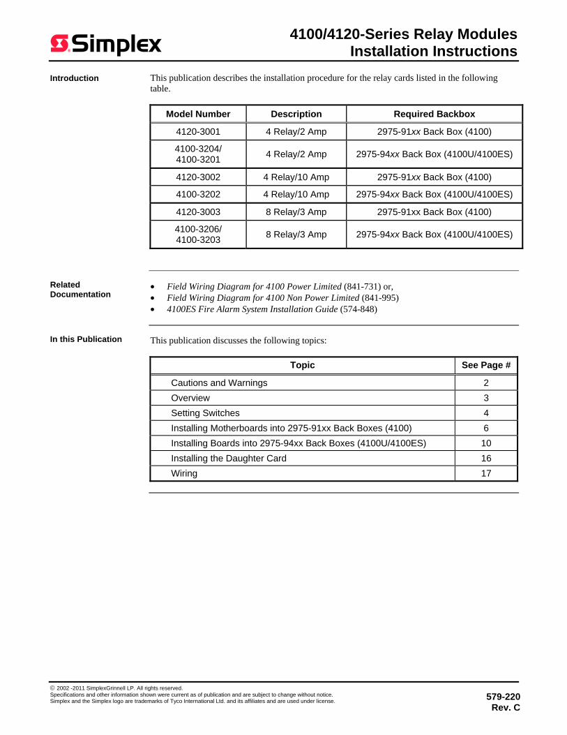
This publication describes the installation procedure for the relay cards listed in the following table.
Model Number Description Required Backbox
4120-3001 4 Relay/2 Amp 2975-91xx Back Box (4100)
4100-3204/ 4100-3201 4 Relay/2 Amp 2975-94xx Back Box (4100U/4100ES)
4120-3002 4 Relay/10 Amp 2975-91xx Back Box (4100)
4100-3202 4 Relay/10 Amp 2975-94xx Back Box (4100U/4100ES)
4120-3003 8 Relay/3 Amp 2975-91xx Back Box (4100)
4100-3206/ 4100-3203 8 Relay/3 Amp 2975-94xx Back Box (4100U/4100ES)
• Field Wiring Diagram for 4100 Power Limited (841-731) or, • Field Wiring Diagram for 4100 Non Power Limited (841-995) • 4100ES Fire Alarm System Installation Guide (574-848)
This publication discusses the following topics:
Topic See Page #
Cautions and Warnings 2 Overview 3 Setting Switches 4 Installing Motherboards into 2975-91xx Back Boxes (4100) 6 Installing Boards into 2975-94xx Back Boxes (4100U/4100ES) 10 Installing the Daughter Card 16 Wiring 17
Introduction
Related Documentation
In this Publication
2
Cautions and Warnings
READ AND SAVE THESE INSTRUCTIONS- Follow the instructions in this installation manual. These instructions must be followed to avoid damage to this product and associated equipment. Product operation and reliability depend upon proper installation.
DO NOT INSTALL ANY SIMPLEX® PRODUCT THAT APPEARS DAMAGED- Upon unpacking your Simplex product, inspect the contents of the carton for shipping damage. If damage is apparent, immediately file a claim with the carrier and notify an authorized Simplex product supplier.
ELECTRICAL HAZARD - Disconnect electrical field power when making any internal adjust-ments or repairs. All repairs should be performed by a representative or authorized agent of your local Simplex product supplier.
STATIC HAZARD - Static electricity can damage components. Handle as follows: • Ground yourself before opening or installing components. • Prior to installation, keep components wrapped in anti-static material at all times.
EYE SAFETY HAZARD - Under certain fiber optic application conditions, the optical output of this device may exceed eye safety limits. Do not use magnification (such as a microscope or other focusing equipment) when viewing the output of this device.
FCC RULES AND REGULATIONS – PART 15 - This equipment has been tested and found to comply with the limits for a Class A digital device pursuant to Part 15 of the FCC Rules. These limits are designed to provide reasonable protection against harmful interference when the equipment is operated in a commercial environment. This equipment generates, uses, and can radiate radio frequency energy and, if not installed and used in accordance with the instruction manual, may cause harmful interference to radio communications. Operation of this equipment in a residential area is likely to cause harmful interference in which case the user will be required to correct the interference at his own expense.
SYSTEM REACCEPTANCE TEST AFTER SOFTWARE CHANGES To ensure proper system operation, this product must be tested in accordance with NFPA 72® after any programming operation or change in site-specific software. Reacceptance testing is required after any change, addition or deletion of system components, or after any modification, repair or adjustment to system hardware or wiring. All components, circuits, system operations, or software functions, known to be affected by a change, must be 100% tested. In addition, to ensure that other operations are not inadvertently affected, at least 10% of initiating devices that are not directly affected by the change, up to a maximum of 50 devices, must also be tested and proper system operation verified. NFPA 72® is a registered trademark of the National Fire Protection Association.
Cautions and Warnings
3
Review the following items for general information about the relay modules. • All relay module contacts are Form C, dry contacts, meaning the Common terminal is
connected to the Normally Closed terminal when the relay’s coil is in the de-energized state.
• Relay operation must be programmed, using the 4100 programmer. Programming a relay involves assigning a software point type to the relay. This point type determines the system list to which the relay point is assigned and consequently the operation of the relay when an alarm, trouble, and supervisory condition occurs.
• Feedback loop circuits function as inputs to the system. Feedback circuits are present on all 4100 relay cards, and on both the 4-relay/10 A and 4-relay/2 A upgrade cards. See below for programming details on the 4100-3206. Typically, feedback circuits connect to a set of NO or NC contacts on a motor or the sail switch on a damper, allowing the state of the device to be monitored. In some situations, the state of the feedback point is used as a trigger within a custom control equation, allowing the system to react in one way when the contact is in one position and another way when the contact is in the other position.
• Always disconnect power from the system before installing a relay module.
From the panel’s perspective, the 4100-3206 appears to be functionally the same as the 4120-3003. The 4100-3206, however, does not have the feedback function that is present in the other assemblies. In the programmer, the feedback points still appear, but are pre-assigned the point type “UNUSED” and have their custom label pre-assigned to read “FEEDBACK NOT AVAILABLE.” If the 4100-3206 is not available as a selection in the version of the Programmer being used, the 4120-3003 can be used to program this card. If the 4120-3003 card is programmed, the feedback points should be left with their default point type. The label should be manually changed to "FEEDBACK NOT AVAILABLE" to avoid confusion when viewing the points.
Install the relay modules in an environment that is within the following: Temperature: 0° to 120° F Humidity: 93% Relative Humidity @ 90° F
Overview
General Information
A Note on Panel Programming for the 4100-3206
Environmental Requirements
4
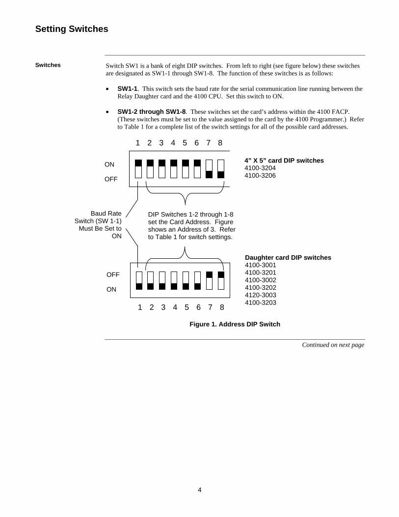
Switch SW1 is a bank of eight DIP switches. From left to right (see figure below) these switches are designated as SW1-1 through SW1-8. The function of these switches is as follows: • SW1-1. This switch sets the baud rate for the serial communication line running between the
Relay Daughter card and the 4100 CPU. Set this switch to ON. • SW1-2 through SW1-8. These switches set the card’s address within the 4100 FACP.
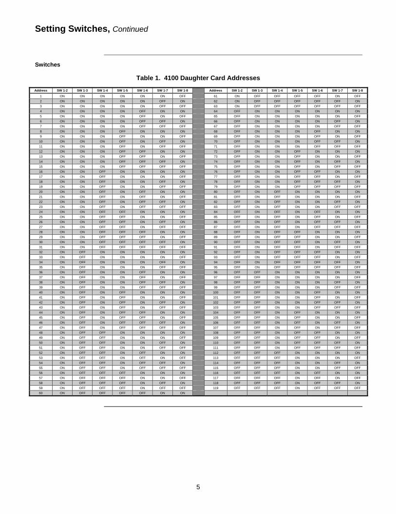
(These switches must be set to the value assigned to the card by the 4100 Programmer.) Refer to Table 1 for a complete list of the switch settings for all of the possible card addresses.
1 87 65432
1 8765432
Figure 1. Address DIP Switch
Continued on next page
Setting Switches
Switches
OFF
ON
DIP Switches 1-2 through 1-8 set the Card Address. Figure shows an Address of 3. Refer to Table 1 for switch settings.
Baud Rate Switch (SW 1-1)
Must Be Set to ON
ON
OFF
4” X 5” card DIP switches 4100-3204 4100-3206
Daughter card DIP switches 4100-3001 4100-3201 4100-3002 4100-3202 4120-3003 4100-3203
5
Setting Switches, Continued
Switches
Table 1. 4100 Daughter Card Addresses
Address SW 1-2 SW 1-3 SW 1-4 SW 1-5 SW 1-6 SW 1-7 SW 1-8 Address SW 1-2 SW 1-3 SW 1-4 SW 1-5 SW 1-6 SW 1-7 SW 1-8
1 ON ON ON ON ON ON OFF 61 ON OFF OFF OFF OFF ON OFF 2 ON ON ON ON ON OFF ON 62 ON OFF OFF OFF OFF OFF ON 3 ON ON ON ON ON OFF OFF 63 ON OFF OFF OFF OFF OFF OFF 4 ON ON ON ON OFF ON ON 64 OFF ON ON ON ON ON ON 5 ON ON ON ON OFF ON OFF 65 OFF ON ON ON ON ON OFF 6 ON ON ON ON OFF OFF ON 66 OFF ON ON ON ON OFF ON 7 ON ON ON ON OFF OFF OFF 67 OFF ON ON ON ON OFF OFF 8 ON ON ON OFF ON ON ON 68 OFF ON ON ON OFF ON ON 9 ON ON ON OFF ON ON OFF 69 OFF ON ON ON OFF ON OFF
10 ON ON ON OFF ON OFF ON 70 OFF ON ON ON OFF OFF ON 11 ON ON ON OFF ON OFF OFF 71 OFF ON ON ON OFF OFF OFF 12 ON ON ON OFF OFF ON ON 72 OFF ON ON OFF ON ON ON 13 ON ON ON OFF OFF ON OFF 73 OFF ON ON OFF ON ON OFF 14 ON ON ON OFF OFF OFF ON 74 OFF ON ON OFF ON OFF ON 15 ON ON ON OFF OFF OFF OFF 75 OFF ON ON OFF ON OFF OFF 16 ON ON OFF ON ON ON ON 76 OFF ON ON OFF OFF ON ON 17 ON ON OFF ON ON ON OFF 77 OFF ON ON OFF OFF ON OFF 18 ON ON OFF ON ON OFF ON 78 OFF ON ON OFF OFF OFF ON 19 ON ON OFF ON ON OFF OFF 79 OFF ON ON OFF OFF OFF OFF 20 ON ON OFF ON OFF ON ON 80 OFF ON OFF ON ON ON ON 21 ON ON OFF ON OFF ON OFF 81 OFF ON OFF ON ON ON OFF 22 ON ON OFF ON OFF OFF ON 82 OFF ON OFF ON ON OFF ON 23 ON ON OFF ON OFF OFF OFF 83 OFF ON OFF ON ON OFF OFF 24 ON ON OFF OFF ON ON ON 84 OFF ON OFF ON OFF ON ON 25 ON ON OFF OFF ON ON OFF 85 OFF ON OFF ON OFF ON OFF 26 ON ON OFF OFF ON OFF ON 86 OFF ON OFF ON OFF OFF ON 27 ON ON OFF OFF ON OFF OFF 87 OFF ON OFF ON OFF OFF OFF 28 ON ON OFF OFF OFF ON ON 88 OFF ON OFF OFF ON ON ON 29 ON ON OFF OFF OFF ON OFF 89 OFF ON OFF OFF ON ON OFF 30 ON ON OFF OFF OFF OFF ON 90 OFF ON OFF OFF ON OFF ON 31 ON ON OFF OFF OFF OFF OFF 91 OFF ON OFF OFF ON OFF OFF 32 ON OFF ON ON ON ON ON 92 OFF ON OFF OFF OFF ON ON 33 ON OFF ON ON ON ON OFF 93 OFF ON OFF OFF OFF ON OFF 34 ON OFF ON ON ON OFF ON 94 OFF ON OFF OFF OFF OFF ON 35 ON OFF ON ON ON OFF OFF 95 OFF ON OFF OFF OFF OFF OFF 36 ON OFF ON ON OFF ON ON 96 OFF OFF ON ON ON ON ON 37 ON OFF ON ON OFF ON OFF 97 OFF OFF ON ON ON ON OFF 38 ON OFF ON ON OFF OFF ON 98 OFF OFF ON ON ON OFF ON 39 ON OFF ON ON OFF OFF OFF 99 OFF OFF ON ON ON OFF OFF 40 ON OFF ON OFF ON ON ON 100 OFF OFF ON ON OFF ON ON 41 ON OFF ON OFF ON ON OFF 101 OFF OFF ON ON OFF ON OFF 42 ON OFF ON OFF ON OFF ON 102 OFF OFF ON ON OFF OFF ON 43 ON OFF ON OFF ON OFF OFF 103 OFF OFF ON ON OFF OFF OFF 44 ON OFF ON OFF OFF ON ON 104 OFF OFF ON OFF ON ON ON 45 ON OFF ON OFF OFF ON OFF 105 OFF OFF ON OFF ON ON OFF 46 ON OFF ON OFF OFF OFF ON 106 OFF OFF ON OFF ON OFF ON 47 ON OFF ON OFF OFF OFF OFF 107 OFF OFF ON OFF ON OFF OFF 48 ON OFF OFF ON ON ON ON 108 OFF OFF ON OFF OFF ON ON 49 ON OFF OFF ON ON ON OFF 109 OFF OFF ON OFF OFF ON OFF 50 ON OFF OFF ON ON OFF ON 110 OFF OFF ON OFF OFF OFF ON 51 ON OFF OFF ON ON OFF OFF 111 OFF OFF ON OFF OFF OFF OFF 52 ON OFF OFF ON OFF ON ON 112 OFF OFF OFF ON ON ON ON 53 ON OFF OFF ON OFF ON OFF 113 OFF OFF OFF ON ON ON OFF 54 ON OFF OFF ON OFF OFF ON 114 OFF OFF OFF ON ON OFF ON 55 ON OFF OFF ON OFF OFF OFF 115 OFF OFF OFF ON ON OFF OFF 56 ON OFF OFF OFF ON ON ON 116 OFF OFF OFF ON OFF ON ON 57 ON OFF OFF OFF ON ON OFF 117 OFF OFF OFF ON OFF ON OFF 58 ON OFF OFF OFF ON OFF ON 118 OFF OFF OFF ON OFF OFF ON 59 ON OFF OFF OFF ON OFF OFF 119 OFF OFF OFF ON OFF OFF OFF 60 ON OFF OFF OFF OFF ON ON
6
The relay modules can be mounted to either 4100 Back Boxes (PID series 2975-91xx) or 4100U/4100ES Back Boxes (PID series 2975-94xx) as follows: • The 4120-3001, -3002, and -3003 are used for systems with 4100 Back Boxes. • The 4100-3201 through -3204 and -3206 are used for systems with 4100U/4100ES Back
Boxes. This section describes mounting the 4120-3001 through -3003 into 4100 Back Boxes.
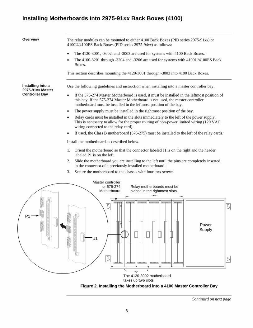
Use the following guidelines and instruction when installing into a master controller bay. • If the 575-274 Master Motherboard is used, it must be installed in the leftmost position of
this bay. If the 575-274 Master Motherboard is not used, the master controller motherboard must be installed in the leftmost position of the bay.
• The power supply must be installed in the rightmost position of the bay. • Relay cards must be installed in the slots immediately to the left of the power supply.
This is necessary to allow for the proper routing of non-power limited wiring (120 VAC wiring connected to the relay card).
• If used, the Class B motherboard (575-275) must be installed to the left of the relay cards.
Install the motherboard as described below. 1. Orient the motherboard so that the connector labeled J1 is on the right and the header
labeled P1 is on the left. 2. Slide the motherboard you are installing to the left until the pins are completely inserted
in the connector of a previously installed motherboard. 3. Secure the motherboard to the chassis with four torx screws.
Figure 2. Installing the Motherboard into a 4100 Master Controller Bay
Continued on next page
Installing Motherboards into 2975-91xx Back Boxes (4100)
Overview
Installing into a 2975-91xx Master Controller Bay
Master controller or 575-274
Motherboard
Power Supply
J1
P1
Relay motherboards must be placed in the rightmost slots.
The 4120-3002 motherboard takes up two slots.

7
Review the following guidelines before mounting the motherboard into a 2975-91xx Expansion Bay. • If a power supply is installed in the bay, it must be installed on the far right of the bay
and any relay modules must be installed in the slots immediately to its left. • Relay cards must be installed in the rightmost possible slots. This is necessary to allow
for the proper routing of non-power limited wiring (typically 120 VAC wiring), which could be connected to a relay module.
• If a 4100/4120-0155 SDACT, 4100-6052 Event Reporting DACT, 4100-6053 Point Reporting DACT, or a 4100/4120-0153 CCDACT is installed in the bay, it must be installed in the far left or far right slot. Neither of these modules contains the J1 or P1 connectors, which are used to distribute power and communications to adjacent modules.
Use the following directions and Figure 3 to install a motherboard into an expansion bay.
1. Orient the motherboard with the connector labeled J1 on the right and the header labeled P1 on the left.
2. Match the connector on the previously installed motherboard with the pins on the motherboard you are installing. Slide the motherboard to the left until the pins are completely inserted in the connector of the previously installed motherboard. If you are installing the leftmost board, the pins will remain unconnected.
3. Secure the motherboard to the chassis with four torx screws.
Figure 3. Installing the Motherboard into a 4100 Expansion Bay 4. If you are installing the leftmost motherboard, connect a 733-525 Power and Communication
Harness. Continue to the next topic to connect the harness.
Continued on next page
Installing Motherboards into 2975-91xx Back Boxes (4100), Continued
Installing into a 2975-91xx Expansion Bay
The motherboard can be installed in any of the eight slots, starting on the far right of the bay.
J1
P1
The 4120-3002 motherboard takes up two slots.

8
If you need to connect a 733-525 Harness to a motherboard, refer to Figure 6 and follow these steps. Make sure to route the power and communication wiring on the left side of the bay. 1. Connect one end of the harness to a motherboard in an adjacent bay.
If the adjacent bay is a master controller bay, connect the harness to the P2 and P3 connectors of the master controller motherboard and continue to step 2. If the adjacent bay is an expansion bay, connect the harness to the P2 and P3 connectors of the motherboard installed in the leftmost slot. (If a 4100/4120-0155 SDACT, 4100-6052 Event Reporting DACT, 4100-6053 Point Reporting DACT, or a 4100/4120-0153 CCDACT occupies the leftmost slot, connect the harness to the motherboard in the second slot from the left.) Connect the harness as follows:
a. Insert the harness connector with the blue wire into the P2 connector. Note that the P2 connector has eight pins. Insert the harness connector on either the top four pins or the bottom four pins, not in the middle.
b. Insert the harness connector with the white wire into the P3 connector. Note that the P3 connector has eight pins. Insert the harness connector on either the top four pins or the bottom four pins, not in the middle.
Continued on next page
Installing Motherboards into 2975-91xx Back Boxes (4100), Continued
Connecting the 733-525 Harness
9
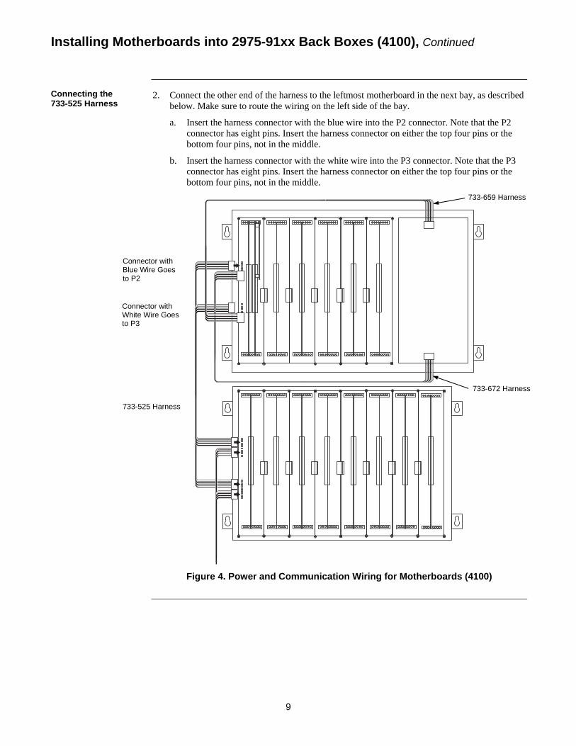
2. Connect the other end of the harness to the leftmost motherboard in the next bay, as described below. Make sure to route the wiring on the left side of the bay.
a. Insert the harness connector with the blue wire into the P2 connector. Note that the P2 connector has eight pins. Insert the harness connector on either the top four pins or the bottom four pins, not in the middle.
b. Insert the harness connector with the white wire into the P3 connector. Note that the P3 connector has eight pins. Insert the harness connector on either the top four pins or the bottom four pins, not in the middle.
Figure 4. Power and Communication Wiring for Motherboards (4100)
Installing Motherboards into 2975-91xx Back Boxes (4100), Continued
Connecting the 733-525 Harness
733-659 Harness
Connector with Blue Wire Goes to P2
Connector with White Wire Goes to P3
733-525 Harness
733-672 Harness
10
The relay modules can be mounted to either 4100 Back Boxes (PID series 2975-91xx) or 4100U/4100ES Back Boxes (PID series 2975-94xx) as follows: • The 4120-3001, -3002, and -3003 are used for systems with 4100 Back Boxes. • The 4100-3201 through -3204 and -3206 are used for systems with 4100U/4100ES Back
Boxes. This section describes mounting the 4100-3201 through -3204 and -3206 into 4100U/4100ES Back Boxes.
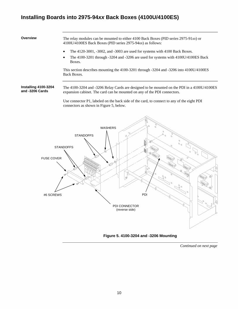
The 4100-3204 and -3206 Relay Cards are designed to be mounted on the PDI in a 4100U/4100ES expansion cabinet. The card can be mounted on any of the PDI connectors. Use connector P1, labeled on the back side of the card, to connect to any of the eight PDI connectors as shown in Figure 5, below.
Figure 5. 4100-3204 and -3206 Mounting
Continued on next page
Installing Boards into 2975-94xx Back Boxes (4100U/4100ES)
Overview
Installing 4100-3204 and -3206 Cards
FUSE COVER
STANDOFFS
#6 SCREWS
WASHERS
PDI CONNECTOR (reverse side)
PDI
STANDOFFS
11
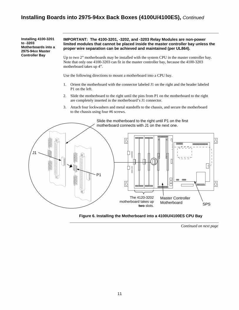
IMPORTANT: The 4100-3201, -3202, and -3203 Relay Modules are non-power limited modules that cannot be placed inside the master controller bay unless the proper wire separation can be achieved and maintained (per UL864). Up to two 2” motherboards may be installed with the system CPU in the master controller bay. Note that only one 4100-3203 can fit in the master controller bay, because the 4100-3203 motherboard takes up 4”. Use the following directions to mount a motherboard into a CPU bay. 1. Orient the motherboard with the connector labeled J1 on the right and the header labeled
P1 on the left.
2. Slide the motherboard to the right until the pins from P1 on the motherboard to the right are completely inserted in the motherboard’s J1 connector.
3. Attach four lockwashers and metal standoffs to the chassis, and secure the motherboard to the chassis using four #6 screws.
Figure 6. Installing the Motherboard into a 4100U/4100ES CPU Bay
Continued on next page
Installing Boards into 2975-94xx Back Boxes (4100U/4100ES), Continued
Installing 4100-3201 to -3203 Motherboards into a 2975-94xx Master Controller Bay
J1
Slide the motherboard to the right until P1 on the first motherboard connects with J1 on the next one.
Master Controller Motherboard SPS
P1
The 4120-3202 motherboard takes up
two slots.
12
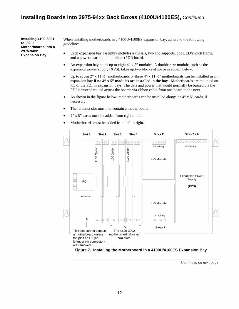
When installing motherboards in a 4100U/4100ES expansion bay, adhere to the following guidelines: • Each expansion bay assembly includes a chassis, two end supports, one LED/switch frame,
and a power distribution interface (PDI) board.
• An expansion bay holds up to eight 4” x 5” modules. A double-size module, such as the expansion power supply (XPS), takes up two blocks of space as shown below.
• Up to seven 2” x 11 ½” motherboards or three 4” x 11 ½” motherboards can be installed in an expansion bay if no 4” x 5” modules are installed in the bay. Motherboards are mounted on top of the PDI in expansion bays. The data and power that would normally be bussed via the PDI is instead routed across the boards via ribbon cable from one board to the next.
• As shown in the figure below, motherboards can be installed alongside 4” x 5” cards, if necessary.
• The leftmost slot must not contain a motherboard.
• 4” x 5” cards must be added from right to left.
• Motherboards must be added from left to right.
No BoardsAllowed
inThis Slot
PDI
4x5 Module
Expansion PowerSupply
(XPS)
4x5 Module
I/O Wiring
I/O Wiring
I/O Wiring
4100
Opt
ion
4100
Opt
ion
4100
Opt
ion
Slot 1 Slot 2 Slot 3 Slot 4 Position5
Position6
Position7 & 8
Figure 7. Installing the Motherboard in a 4100U/4100ES Expansion Bay
Continued on next page
Installing Boards into 2975-94xx Back Boxes (4100U/4100ES), Continued
Installing 4100-3201 to -3203 Motherboards into a 2975-94xx Expansion Bay
Block E Slots 7 + 8
Block F The 4120-3002
motherboard takes up two slots.
This slot cannot contain a motherboard unless the pins on P1 (or leftmost pin connector) are removed.
13
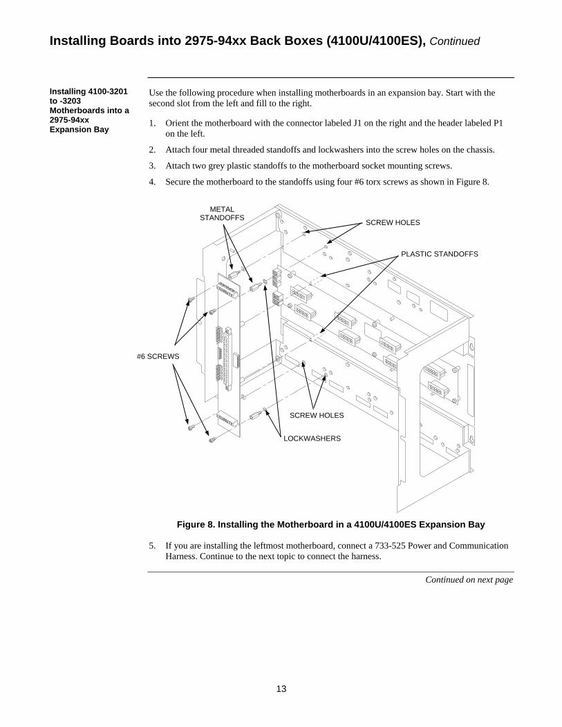
Use the following procedure when installing motherboards in an expansion bay. Start with the second slot from the left and fill to the right.
1. Orient the motherboard with the connector labeled J1 on the right and the header labeled P1 on the left.
2. Attach four metal threaded standoffs and lockwashers into the screw holes on the chassis.
3. Attach two grey plastic standoffs to the motherboard socket mounting screws.
4. Secure the motherboard to the standoffs using four #6 torx screws as shown in Figure 8.
Figure 8. Installing the Motherboard in a 4100U/4100ES Expansion Bay
5. If you are installing the leftmost motherboard, connect a 733-525 Power and Communication
Harness. Continue to the next topic to connect the harness.
Continued on next page
Installing Boards into 2975-94xx Back Boxes (4100U/4100ES), Continued
Installing 4100-3201 to -3203 Motherboards into a 2975-94xx Expansion Bay
METAL STANDOFFS
#6 SCREWS
LOCKWASHERS
SCREW HOLES
SCREW HOLES
PLASTIC STANDOFFS
14
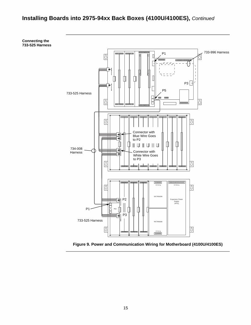
If you need to connect a 733-525 Harness to a motherboard, refer to Figure 9 and follow these steps. Make sure to route the power and communication wiring on the left side of the bay. 1. Connect one end of the harness to a motherboard in an adjacent bay.
If the adjacent bay is a CPU bay with no additional motherboards, connect the harness to the P8 and P7 connectors of the CPU motherboard.
• Insert the harness connector with the blue wire into the P8 connector. Note that the P8 connector has eight pins. Insert the harness connector on either the top four pins or the bottom four pins, not in the middle.
• Insert the harness connector with the white wire into the P7 connector. Note that the P7 connector has eight pins. Insert the harness connector on either the top four pins or the bottom four pins, not in the middle.
If the adjacent bay is an expansion bay or a CPU bay with additional motherboards, connect the harness to the P2 and P3 connectors of the motherboard installed in the leftmost slot. (If a 4100/4120-0155 SDACT, 4100-6052 Event Reporting DACT, 4100-6053 Point Reporting DACT, or a 4100/4120-0153 CCDACT occupies the leftmost slot, connect the harness to the motherboard in the second slot from the left.) Connect the harness as follows:
• Insert the harness connector with the blue wire into the P2 connector. Note that the P2 connector has eight pins. Insert the harness connector on either the top four pins or the bottom four pins, not in the middle.
• Insert the harness connector with the white wire into the P3 connector. Note that the P3 connector has eight pins. Insert the harness connector on either the top four pins or the bottom four pins, not in the middle.
2. Connect the other end of the harness to the leftmost motherboard in the next bay, as described below. Make sure to route the wiring on the left side of the bay.
• Insert the harness connector with the blue wire into the P2 connector. Note that the P2 connector has eight pins. Insert the harness connector on either the top four pins or the bottom four pins, not in the middle.
• Insert the harness connector with the white wire into the P3 connector. Note that the P3 connector has eight pins. Insert the harness connector on either the top four pins or the bottom four pins, not in the middle.
Continued on next page
Installing Boards into 2975-94xx Back Boxes (4100U/4100ES), Continued
Connecting the 733-525 Harness
15
Figure 9. Power and Communication Wiring for Motherboard (4100U/4100ES)
I/O WiringI/O Wiring
PDI
I/O Wiring
4x5 Module
4x5 Module
Expansion PowerSupply(XPS)
Installing Boards into 2975-94xx Back Boxes (4100U/4100ES), Continued
Connecting the 733-525 Harness
733-525 Harness
733-996 Harness
733-525 Harness
Connector with Blue Wire Goes to P2
Connector with White Wire Goes to P3
734-008 Harness
P3
P1
P1
P5
P2
P3
16
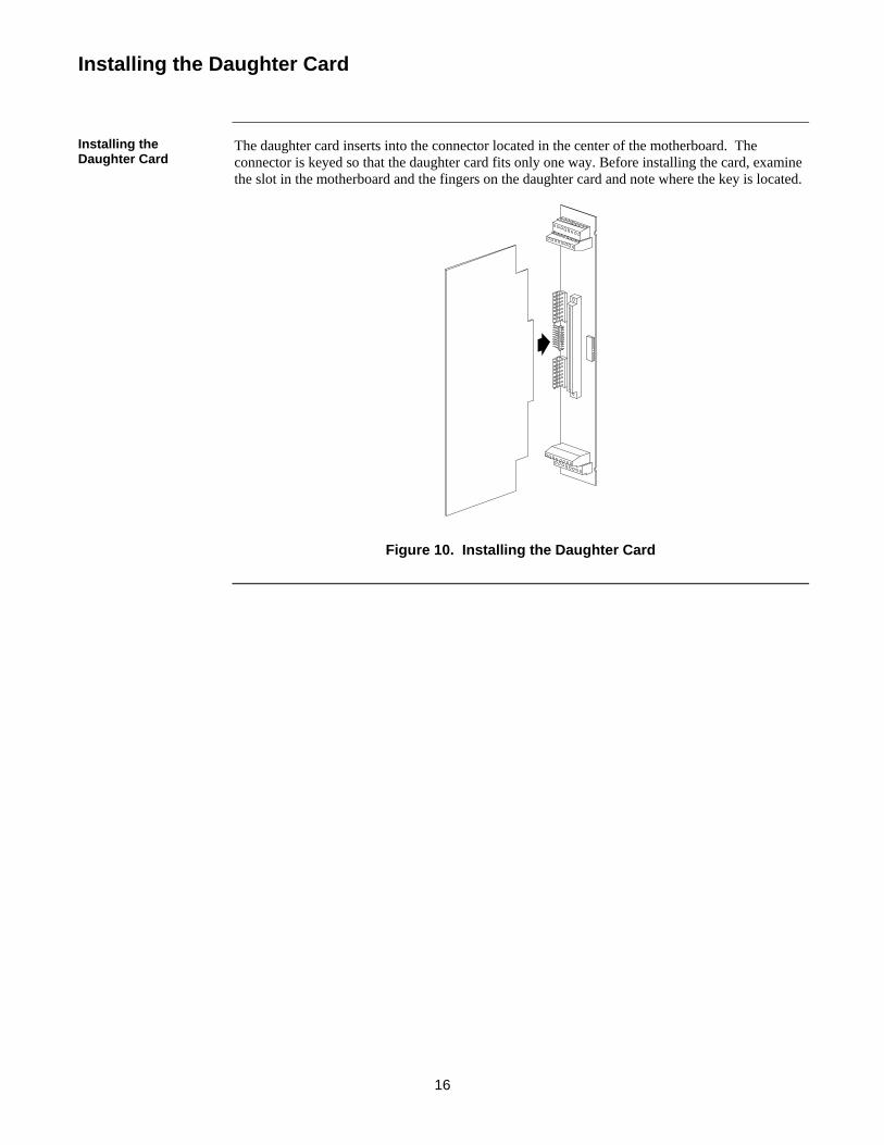
The daughter card inserts into the connector located in the center of the motherboard. The connector is keyed so that the daughter card fits only one way. Before installing the card, examine the slot in the motherboard and the fingers on the daughter card and note where the key is located.
Figure 10. Installing the Daughter Card
Installing the Daughter Card
Installing the Daughter Card

17
This section contains guidelines and instructions for wiring the relay modules.
Make sure these guidelines are accounted for before wiring: • All wires must be 18 AWG, twisted/shielded pair. • All wiring is supervised. • Conductors must test free of all grounds. • Power must come from a Simplex-approved power supply. • All wiring must be done using copper conductors only, unless noted otherwise. • If shielded wire is used,
- the metallic continuity of the shield must be maintained throughout the entire cable length.
- the entire length of the cable must have a resistance greater than 1 Megohm to earth ground.
• Underground wiring must be free of all water. • In areas of high lightning activity, or in areas that have large power surges, the
2081-9027 Transient Suppressor should be used on monitor points. • Wires must not be run through elevator shafts. • Wires that run in plenum must be in conduit. • Splicing is permitted. All spliced connections must either be soldered (resin-core solder),
crimped in metal sleeves, or encapsulated with an epoxy resin. When soldering or crimped metal sleeves are used, the junction must be insulated with a high-grade electrical tape that is as sound as the original insulating jacket. Shield continuity must be maintained throughout.
• A system ground must be provided for earth detection and lightning protection devices. This connection must comply with approved earth detection per NFPA780.
• Only system wiring can be run together in the same conduit.
• Any wiring leaving the building requires overload protectors (2081-9044). Use one overvoltage protector where wiring leaves the building and another where the wiring enters the other building.
Continued on next page
Wiring
Introduction
General Guidelines
W
PG
Wiring, C
Power-LimitedGuidelines
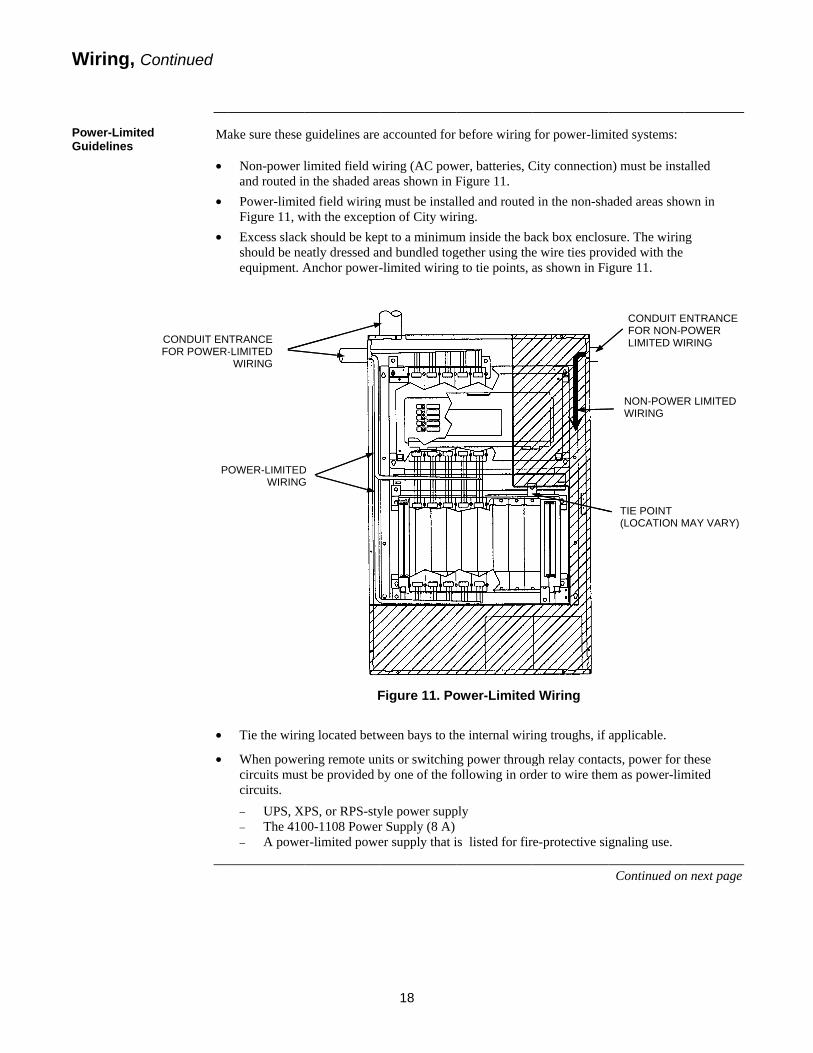
Ma •
•
•
•
•
ontinued
d
CONDUIT ENFOR POWER-
P
ake sure these
Non-power land routed inPower-limiteFigure 11, wExcess slackshould be neequipment. A
Tie the wirin
When powercircuits mustcircuits. − UPS, X− The 410− A powe
TRANCE -LIMITED
WIRING
OWER-LIMITEDWIRING
guidelines are
limited field wn the shaded ared field wiring
with the exceptik should be kepeatly dressed anAnchor power-
F
ng located betw
ring remote unt be provided b
PS, or RPS-sty00-1108 Powerer-limited powe
D G
18
accounted for
wiring (AC powreas shown in F
g must be instalion of City wirpt to a minimumnd bundled tog-limited wiring
Figure 11. Po
ween bays to th
nits or switchinby one of the fo
yle power suppr Supply (8 A)er supply that i
before wiring
wer, batteries, CFigure 11. lled and routedring. m inside the bagether using theg to tie points, a
ower-Limited
he internal wiri
ng power througfollowing in ord
ply
is listed for fir
for power-lim
City connection
d in the non-sha
ack box enclose wire ties provas shown in Fi
d Wiring
ing troughs, if
gh relay contacder to wire them
re-protective si
mited systems:
n) must be inst
aded areas sho
sure. The wirinvided with the igure 11.
applicable.
cts, power for tm as power-lim
gnaling use.
Continued on
CONDUIT EFOR NON-PLIMITED WI
TIE POINT (LOCATION M
NON-POWEWIRING
talled
wn in
ng
these mited
n next page
ENTRANCE POWER IRING
MAY VARY)
R LIMITED
19
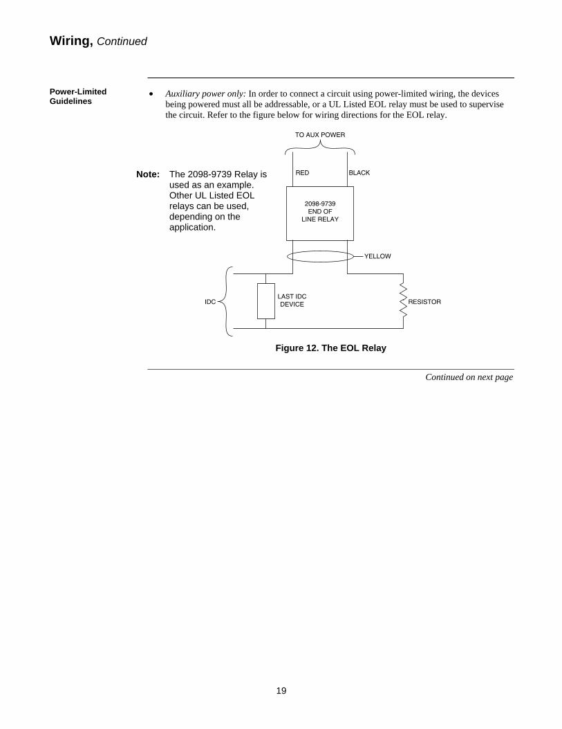
• Auxiliary power only: In order to connect a circuit using power-limited wiring, the devices being powered must all be addressable, or a UL Listed EOL relay must be used to supervise the circuit. Refer to the figure below for wiring directions for the EOL relay.
Figure 12. The EOL Relay
Continued on next page
2098-9739END OF
LINE RELAY
TO AUX POWER
RED BLACK
LAST IDCDEVICE
YELLOW
RESISTORIDC
Wiring, Continued
Power-Limited Guidelines
Note: The 2098-9739 Relay is used as an example. Other UL Listed EOL relays can be used, depending on the application.
20
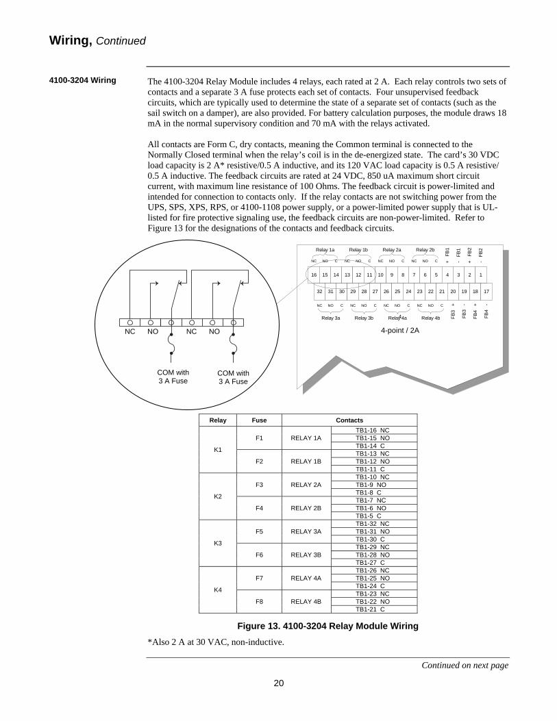
The 4100-3204 Relay Module includes 4 relays, each rated at 2 A. Each relay controls two sets of contacts and a separate 3 A fuse protects each set of contacts. Four unsupervised feedback circuits, which are typically used to determine the state of a separate set of contacts (such as the sail switch on a damper), are also provided. For battery calculation purposes, the module draws 18 mA in the normal supervisory condition and 70 mA with the relays activated. All contacts are Form C, dry contacts, meaning the Common terminal is connected to the Normally Closed terminal when the relay’s coil is in the de-energized state. The card’s 30 VDC load capacity is 2 A* resistive/0.5 A inductive, and its 120 VAC load capacity is 0.5 A resistive/ 0.5 A inductive. The feedback circuits are rated at 24 VDC, 850 uA maximum short circuit current, with maximum line resistance of 100 Ohms. The feedback circuit is power-limited and intended for connection to contacts only. If the relay contacts are not switching power from the UPS, SPS, XPS, RPS, or 4100-1108 power supply, or a power-limited power supply that is UL-listed for fire protective signaling use, the feedback circuits are non-power-limited. Refer to Figure 13 for the designations of the contacts and feedback circuits.
Figure 13. 4100-3204 Relay Module Wiring
*Also 2 A at 30 VAC, non-inductive.
Continued on next page
4
+ F
B1
- F
B1
+ F
B2
- F
B2
FB3
+
FB3
-
FB4
+
FB4
-
4-point / 2A
Relay 1a Relay 1b Relay 2a Relay 2b
NC NO C NC NO C NC NO C NC NO C
NC NO C NC NO C NC NO C NC NO C
Relay 3a Relay 3b Relay 4a Relay 4b
16 15 14 13 12 11 10 9 8 7 6 5
32 31 30 29 28 27 26 25 24 23 22 21
4 3 2 1
20 19 18 17
Relay 1a Relay 1b
NC NO C NC NO C
16 15 14 13 12 11
3AFuse
3AFuse
Wiring, Continued
4100-3204 Wiring
Relay Fuse Contacts
K1
F1 RELAY 1A TB1-16 NC TB1-15 NO TB1-14 C
F2 RELAY 1B TB1-13 NC TB1-12 NO TB1-11 C
K2
F3 RELAY 2A TB1-10 NC TB1-9 NO TB1-8 C
F4 RELAY 2B TB1-7 NC TB1-6 NO TB1-5 C
K3
F5 RELAY 3A TB1-32 NC TB1-31 NO TB1-30 C
F6 RELAY 3B TB1-29 NC TB1-28 NO TB1-27 C
K4
F7 RELAY 4A TB1-26 NC TB1-25 NO TB1-24 C
F8 RELAY 4B TB1-23 NC TB1-22 NO TB1-21 C
COM with 3 A Fuse
COM with 3 A Fuse
NC NO NC NO
21
Relay Fuse Contacts
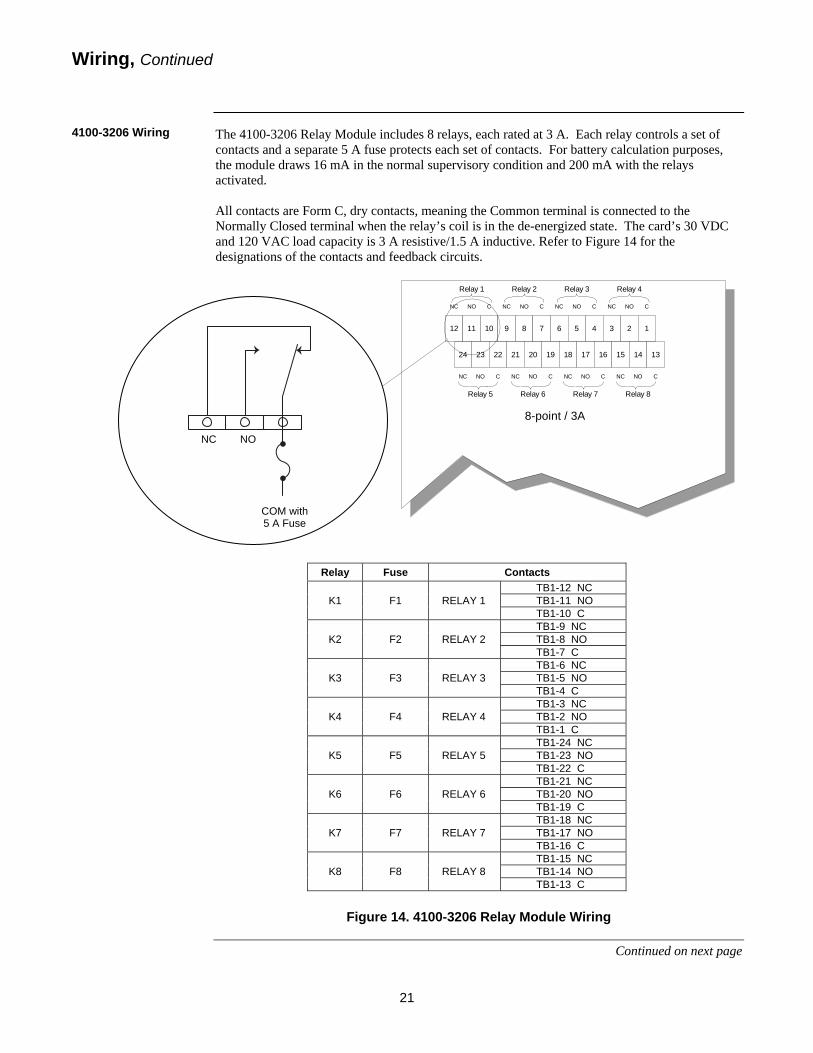
K1 F1 RELAY 1 TB1-12 NC TB1-11 NO TB1-10 C
K2 F2 RELAY 2 TB1-9 NC TB1-8 NO TB1-7 C
K3 F3 RELAY 3 TB1-6 NC TB1-5 NO TB1-4 C
K4 F4 RELAY 4 TB1-3 NC TB1-2 NO TB1-1 C
K5 F5 RELAY 5 TB1-24 NC TB1-23 NO TB1-22 C
K6 F6 RELAY 6 TB1-21 NC TB1-20 NO TB1-19 C
K7 F7 RELAY 7 TB1-18 NC TB1-17 NO TB1-16 C
K8 F8 RELAY 8 TB1-15 NC TB1-14 NO TB1-13 C
The 4100-3206 Relay Module includes 8 relays, each rated at 3 A. Each relay controls a set of contacts and a separate 5 A fuse protects each set of contacts. For battery calculation purposes, the module draws 16 mA in the normal supervisory condition and 200 mA with the relays activated. All contacts are Form C, dry contacts, meaning the Common terminal is connected to the Normally Closed terminal when the relay’s coil is in the de-energized state. The card’s 30 VDC and 120 VAC load capacity is 3 A resistive/1.5 A inductive. Refer to Figure 14 for the designations of the contacts and feedback circuits.
Figure 14. 4100-3206 Relay Module Wiring
Continued on next page
8-point / 3A
Relay 1 Relay 2 Relay 3 Relay 4
Relay 5 Relay 6 Relay 7 Relay 8
NC NO C NC NO C NC NO C NC NO C
NC NO C NC NO C NC NO C NC NO C
12 11 10 9 8 7 6 5 4 3 2 1
24 23 22 21 20 19 18 17 16 15 14 13Relay 1
NC NO C
12 11 10
5AFuse
Wiring, Continued
4100-3206 Wiring
COM with 5 A Fuse
NC NO
22
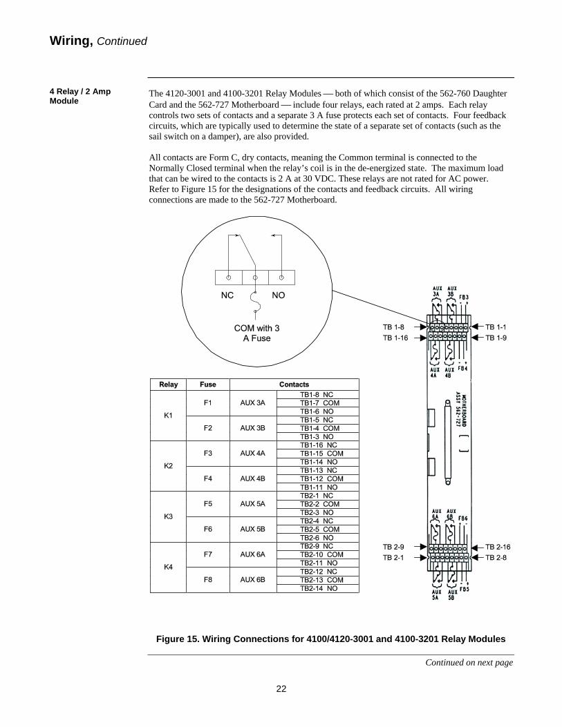
The 4120-3001 and 4100-3201 Relay Modules ⎯ both of which consist of the 562-760 Daughter Card and the 562-727 Motherboard ⎯ include four relays, each rated at 2 amps. Each relay controls two sets of contacts and a separate 3 A fuse protects each set of contacts. Four feedback circuits, which are typically used to determine the state of a separate set of contacts (such as the sail switch on a damper), are also provided. All contacts are Form C, dry contacts, meaning the Common terminal is connected to the Normally Closed terminal when the relay’s coil is in the de-energized state. The maximum load that can be wired to the contacts is 2 A at 30 VDC. These relays are not rated for AC power. Refer to Figure 15 for the designations of the contacts and feedback circuits. All wiring connections are made to the 562-727 Motherboard.
Figure 15. Wiring Connections for 4100/4120-3001 and 4100-3201 Relay Modules
Continued on next page
Wiring, Continued
4 Relay / 2 Amp Module
W
4M
Wiring, C
4 Relay / 10 AmModule
ThCaat setsep AlNothaanNC
F
ontinued
mp
Relay
K1
K2
K3
K4
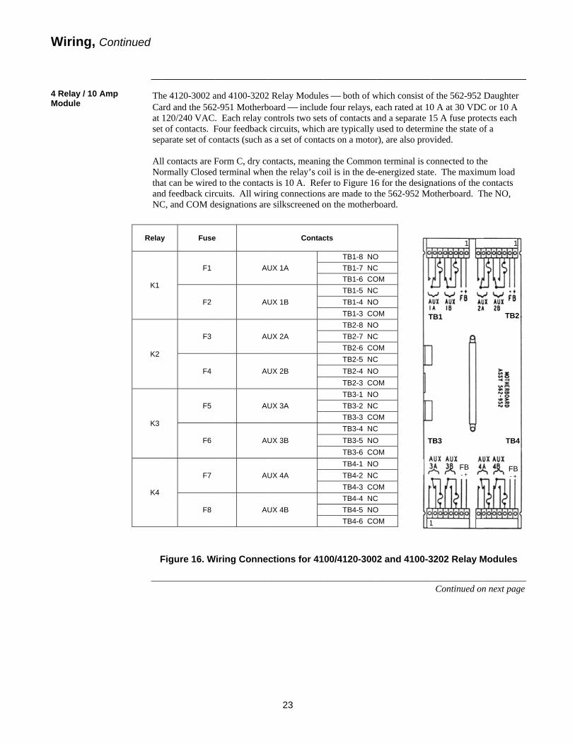
he 4120-3002 aard and the 562120/240 VACt of contacts. Fparate set of co
ll contacts are Formally Closedat can be wiredd feedback circC, and COM de
Figure 16. W
y Fuse
F1
F2
F3
F4
F5
F6
F7
F8
and 4100-32022-951 Motherb. Each relay coFour feedback ontacts (such a
Form C, dry cod terminal whend to the contactcuits. All wirinesignations are
Wiring Connec
e
AU
AU
AU
AU
AU
AU
AU
AU
23
Relay Moduleoard ⎯ includontrols two setcircuits, whichs a set of conta
ontacts, meaninn the relay’s cots is 10 A. Refng connectionse silkscreened o
ctions for 41
Contac
UX 1A
UX 1B
UX 2A
UX 2B
UX 3A
UX 3B
UX 4A
UX 4B
es ⎯ both of wde four relays, ets of contacts ah are typically acts on a motor
ng the Commooil is in the de-fer to Figure 16s are made to ton the motherb
00/4120-300
cts
TB1-8 NOTB1-7 NCTB1-6 COTB1-5 NCTB1-4 NOTB1-3 COTB2-8 NOTB2-7 NCTB2-6 COTB2-5 NCTB2-4 NOTB2-3 COTB3-1 NOTB3-2 NCTB3-3 COTB3-4 NCTB3-5 NOTB3-6 COTB4-1 NOTB4-2 NCTB4-3 COTB4-4 NCTB4-5 NOTB4-6 CO
which consist oeach rated at 10and a separate 1used to determr), are also prov
n terminal is c-energized stat6 for the designthe 562-952 Mboard.
2 and 4100-3
O C OM C O OM O C OM C O OM O C OM C O OM O C OM C O OM
T
T
1
of the 562-952 D0 A at 30 VDC15 A fuse prote
mine the state ovided.
onnected to thee. The maximnations of the cotherboard. Th
3202 Relay M
Continued on
FB - +
TB1
TB3
1
1 1
Daughter C or 10 A ects each f a
e mum load
contacts he NO,
Modules
n next page
FB - +
TB2
TB4
1
579-220 Rev. C
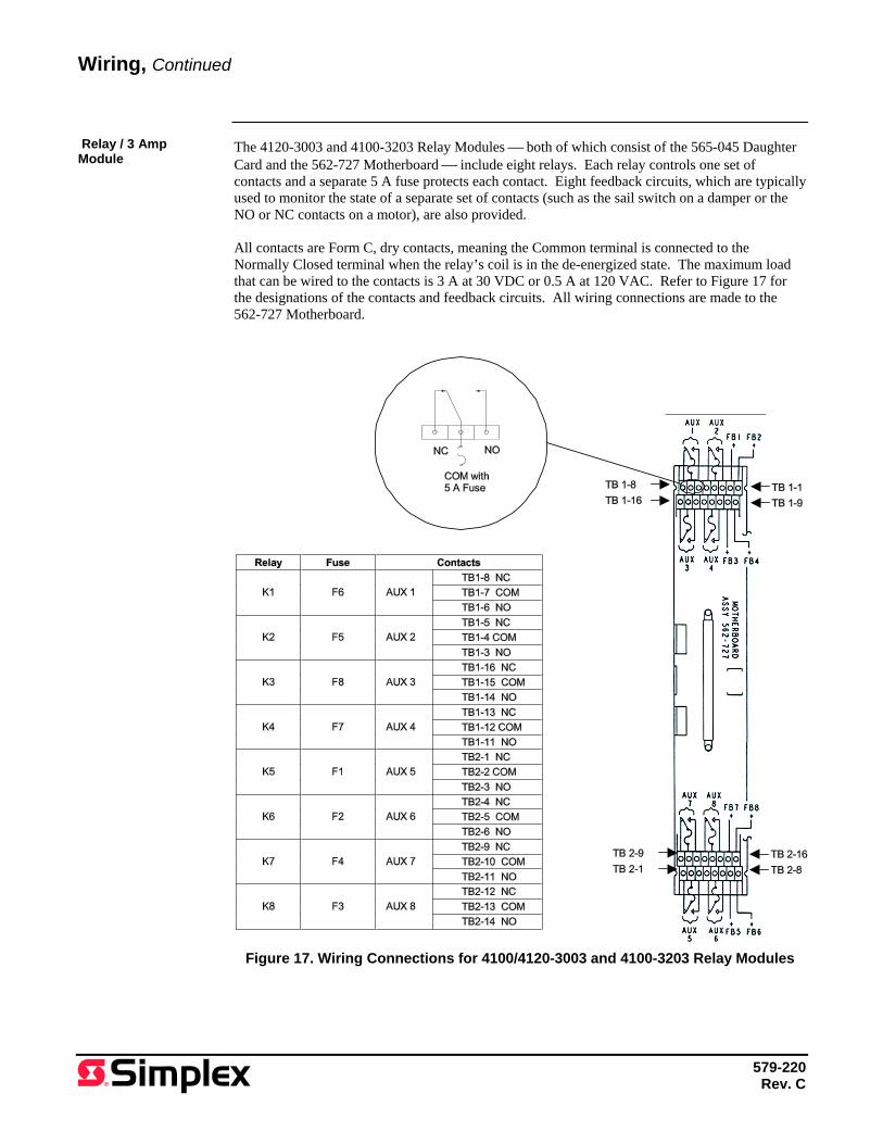
The 4120-3003 and 4100-3203 Relay Modules ⎯ both of which consist of the 565-045 Daughter Card and the 562-727 Motherboard ⎯ include eight relays. Each relay controls one set of contacts and a separate 5 A fuse protects each contact. Eight feedback circuits, which are typically used to monitor the state of a separate set of contacts (such as the sail switch on a damper or the NO or NC contacts on a motor), are also provided. All contacts are Form C, dry contacts, meaning the Common terminal is connected to the Normally Closed terminal when the relay’s coil is in the de-energized state. The maximum load that can be wired to the contacts is 3 A at 30 VDC or 0.5 A at 120 VAC. Refer to Figure 17 for the designations of the contacts and feedback circuits. All wiring connections are made to the 562-727 Motherboard.
Figure 17. Wiring Connections for 4100/4120-3003 and 4100-3203 Relay Modules
Wiring, Continued
Relay / 3 Amp Module