Embed Size (px)
Citation preview
41
Multi-slice CT Technology 3Thomas Flohr and Bernd Ohnesorge
C o n t e n t s
3.1 Evolution from 1 to 64 Slices 41
3.2 Principles of Multi-slice CT System Design 45
3.3 Multi-slice CT Acquisition and Reconstruction for Body Imaging 523.3.1 Defi nition of the Pitch 523.3.2 The Cone-Angle Problem in Multi-slice CT 533.3.3 Multi-slice Spiral Reconstruction Neglecting the Cone-Beam Geometry 543.3.3.1 180° and 360° Multi-slice Linear Interpolation 543.3.3.2 z-Filter Approaches 563.3.4 Multi-slice Spiral Reconstruction with Cone-Beam Algorithms 583.3.4.1 Overview of Cone-Beam Reconstruction Algorithms 583.3.4.2 3D Filtered Back-Projection 583.3.4.3 Adaptive Multiple Plane Reconstruction 593.3.4.4 Weighted Hyperplane Reconstruction 613.3.4.5 Double z-Sampling 62
References 67
and-shoot» mode, the so-called sequence-scan technique. Consequently, axial scanning required long examination times because of the inter-scan delays necessary to move the table incrementally from one scan position to the next, and it was prone to misregistration of anatomical details due to the potential movement of relevant anatomical struc-tures between two scans, e. g., by patient motion, breathing, or swallowing. With spiral CT, the patient table is continuously translated while scan data are acquired. The prerequisite for the success of spiral scanning was the introduction of slip-ring gantries, which eliminated the need to rewind the gantry after each rotation and enabled continuous data acquisition during multiple rotations. For the first time, volume data could be acquired without the danger of misregistration or double-registration of anatomical details. Images could be reconstructed at any position along the patient axis (longitudinal axis), and overlapping image reconstruction could be used to improve longitudinal resolution. Volume data became the very basis for applications such as CT angiography (Rubin 1995), which has revolu-tionized non-invasive assessment of vascular dis-ease. The ability to acquire volume data also paved the way for the development of 3D image-process-ing techniques, such as multi-planar reformations (MPR), maximum intensity projections (MIP), sur-face-shaded displays (SSD), and volume-rendering techniques (VRT) (Napel 1993). These have become vital components of medical imaging today.
Ideally, volume data are of high spatial resolu-tion and isotropic in nature, i.e., the data element («voxel») of each image is of equal dimensions in all three spatial axes, and forms the basis for image display in arbitrarily oriented imaging planes. For most clinical scenarios, however, single-slice spiral
3.1 Evolution from 1 to 64 Slices
Computed tomography (CT) was introduced in the early 1970s and has revolutionized not only diag-nostic radiology, but also the entire practice of medicine. In the early 1990s, the introduction of spiral CT constituted a further evolutionary step in the development and ongoing refinement of CT imaging techniques (Kalender 1990, Crawford 1990). Until then, the examination volume had to be covered by subsequent axial scans in a «step-
42 Chapter 3 · Multi-slice CT Technology
CT with 1-s gantry rotation time is unable to fulfill these prerequisites. To avoid motion artifacts and to optimally use the contrast bolus, spiral CT body examinations need to be completed within a certain timeframe of, ordinarily, one patient breath-hold (25–30 s). If a large scan range, such as the entire thorax or abdomen (30 cm), has to be covered with single-slice spiral CT within a single breath-hold, a thick collimation of 5–8 mm must be used. While the in-plane resolution of a CT image depends on the system geometry and on the reconstruction kernel selected by the user, the longitudinal (z-) resolution is determined by the collimated slice width and the spiral interpolation algorithm. A thick collima-tion of 5–8 mm results in a considerable mismatch between the longitudinal resolution and the in-plane resolution, which is usually 0.5–0.7 mm depending on the reconstruction kernel. Thus, with single-slice spiral CT, the ideal of isotropic resolution can only be achieved for very limited scan ranges (Kalender 1995).
Strategies to achieve more substantial volume coverage with improved longitudinal resolution have included the simultaneous acquisition of more than one slice at a time and a reduction of the gantry rotation time. Interestingly, the very first medical CT scanners were 2-slice systems, such as the EMI head scanner, introduced in 1972, or the Siemens SIRE-TOM, introduced in 1974. With the advent of whole-body fan-beam CT systems for general radiology, 2-slice acquisition was no longer used. Apart from a dedicated 2-slice system for cardiac applications, the IMATRON C-100, introduced in 1984, the first step towards multi-slice acquisition in general radi-ology was a 2-slice CT scanner introduced in 1993 (Elscint TWIN) (Liang 1996). In 1998, all major CT manufacturers introduced multi-slice CT (MSCT) systems, which typically offered simultaneous acquisition of 4 slices at a rotation time of down to 0.5 s. This was a considerable improvement in scan speed and longitudinal resolution and offered better utilization of the available X-ray power (Klingen-beck 1999, McCollough 1999, Ohnesorge 1999, Hu 2000). These developments were quickly recog-nized as revolutionary improvements that would eventually enable users to do real isotropic 3D imag-ing. Consequently, all vendors pushed towards more and more slices, turning the number of slices into
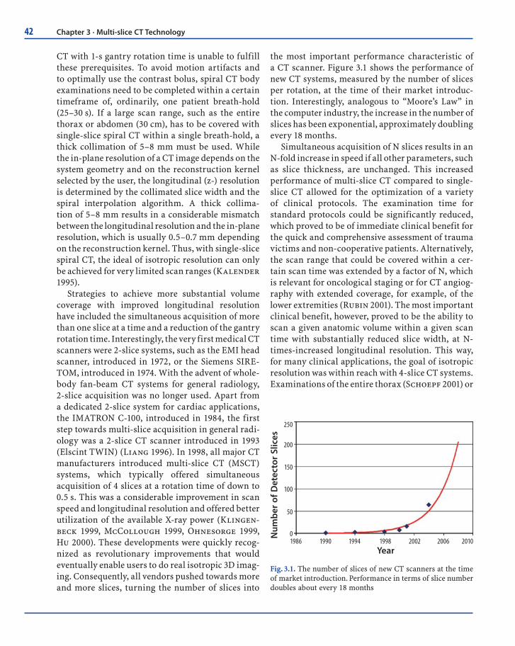
the most important performance characteristic of a CT scanner. Figure 3.1 shows the performance of new CT systems, measured by the number of slices per rotation, at the time of their market introduc-tion. Interestingly, analogous to “Moore’s Law” in the computer industry, the increase in the number of slices has been exponential, approximately doubling every 18 months.
Simultaneous acquisition of N slices results in an N-fold increase in speed if all other parameters, such as slice thickness, are unchanged. This increased performance of multi-slice CT compared to single-slice CT allowed for the optimization of a variety of clinical protocols. The examination time for standard protocols could be significantly reduced, which proved to be of immediate clinical benefit for the quick and comprehensive assessment of trauma victims and non-cooperative patients. Alternatively, the scan range that could be covered within a cer-tain scan time was extended by a factor of N, which is relevant for oncological staging or for CT angiog-raphy with extended coverage, for example, of the lower extremities (Rubin 2001). The most important clinical benefit, however, proved to be the ability to scan a given anatomic volume within a given scan time with substantially reduced slice width, at N-times-increased longitudinal resolution. This way, for many clinical applications, the goal of isotropic resolution was within reach with 4-slice CT systems. Examinations of the entire thorax (Schoepf 2001) or
Year
250
200
150
100
50
01986 1990 1994 1998 2002 2006 2010
Num
ber
of D
etec
tor
Slic
es
Fig. 3.1. The number of slices of new CT scanners at the time of market introduction. Performance in terms of slice number doubles about every 18 months
43
abdomen (Klingenbeck 1999) could now routinely be performed with a collimated slice width of 1 mm or 1.25 mm. Multi-slice CT also expanded into areas previously considered beyond the scope of conven-tional spiral CT scanners, such as routine vascular diagnosis (Ohnesorge 2001, Schoepf 2003), high-resolution low dose CT of the lung (Swensen 2002), virtual CT colonography (Macari 2002, Wessling 2003), and cardiac imaging with the addition of ECG gating capability. The introduction of 4-slice CT with a gantry rotation time of 0.5 s and dedicated image-reconstruction approaches represented a break-through for mechanical CT in cardiac imaging. The temporal resolution for the acquisition of an image was improved to 250 ms and less (Kachelriess 2000, Ohnesorge 2000), sufficient for motion-free imaging of the heart in the mid- to end-diastolic phase at slow to moderate heart rates (Hong 2001). With four simultaneously acquired slices, coverage of the entire heart volume with thin slices and ECG-gating within a single breath-hold became feasible, enabling non-invasive visualization of the cardiac morphology and coronary arteries (Ohnesorge 2000, Achenbach 2000, Knez 2000, Nieman 2001).
Despite all these promising advances, clinical challenges and limitations remained for 4-slice CT systems. True isotropic resolution for routine applications had not yet been achieved, since a lon-gitudinal resolution of about 1 mm does not fully match the in-plane resolution of about 0.5–0.7 mm in a routine scan of the chest or abdomen. For large volumes, such as CT angiography of lower-extrem-ity run-off (Rubin 2001), thicker (i.e. 2.5 mm) col-limated slices had to be chosen to complete the scan within a reasonable timeframe. Scan times were often too long to allow image acquisition during pure arterial phase. For CT angiography of the circle of Willis, for instance, a scan range of about 100 mm must be covered (Villablanca 2002). With 4-slice CT, at a collimated slice width of 1 mm, a pitch of 1.5, and 0.5.s gantry rotation time, this volume can be covered in a scan time of about 9 s, which is not fast enough to avoid venous overlay assuming a cerebral circulation time of less than 5 s. For ECG-gated cor-onary CT angiography, stents or severely calcified arteries constituted a diagnostic dilemma, mainly due to partial volume artifacts as a consequence of insufficient longitudinal resolution (Nieman 2001).
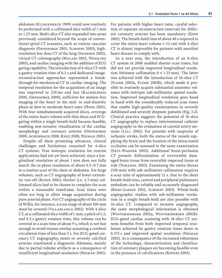
For patients with higher heart rates, careful selec-tion of separate reconstruction intervals for differ-ent coronary arteries has been mandatory (Kopp 2001). The breath-hold time of about 40 s required to cover the entire heart volume (~12 cm) with 4-slice CT is almost impossible for patients with manifest heart disease to comply with.
As a next step, the introduction of an 8-slice CT system in 2000 enabled shorter scan times, but did not yet provide improved longitudinal resolu-tion (thinnest collimation 8 × 1.25 mm). The latter was achieved with the introduction of 16-slice CT (Flohr 2002a, Flohr 2002b), which made it pos-sible to routinely acquire substantial anatomic vol-umes with isotropic sub-millimeter spatial resolu-tion. Improved longitudinal resolution goes hand in hand with the considerably reduced scan times that enable high-quality examinations in severely debilitated and severely dyspneic patients (Fig. 3.2). Clinical practice suggests the potential of 16-slice CT angiography to replace interventional catheter angiography in the evaluation of carotid artery ste-nosis (Lell 2002). For patients with suspicion of ischemic stroke, both the status of the vessels sup-plying the brain and the location of the intracranial occlusion can be assessed in the same examination (Ertl-Wagner 2002). Additional brain-perfusion CT permits differentiation of irreversibly dam-aged brain tissue from reversibly impaired tissue at risk (Tomandl 2003). Examining the entire thorax (350 mm) with sub-millimeter collimation requires a scan time of approximately 11 s. Due to the short breath-hold time, central and peripheral pulmonary embolism can be reliably and accurately diagnosed (Remy-Jardin 2002, Schoepf 2003). Whole-body angiographic studies with sub-millimeter resolu-tion in a single breath-hold are also possible with 16-slice CT. Compared to invasive angiography, the same morphological information is obtained (Wintersperger 2002a, Wintersperger 2002b). ECG-gated cardiac scanning with 16-slice CT sys-tems benefits from both improved temporal reso-lution achieved by gantry rotation times down to 0.375 s and improved spatial resolution (Nieman 2002). As a consequence of the increased robustness of the technology, characterization and classifica-tion of coronary plaques are becoming feasible even in the presence of calcifications (Ropers 2003).
3.1 · Evolution from 1 to 64 Slices
44 Chapter 3 · Multi-slice CT Technology
ba c
Fig. 3.2a–c. Case study consisting of axial slices and coronal multi-planar reformations (MPRs) of a thorax examination illus-trating the clinical performance of a single-slice CT (7-mm slices, 30 s), b 4-slice CT (1.25-mm slices, 30 s) and c 16-slice CT (0.75-mm slices, 10 s). The difference in diagnostic image quality is most obvious in the MPRs. The single-slice and 4-slice images were synthesized from the 16-slice CT data. (Case courtesy of the Medical University of South Carolina, Charleston, USA)
Currently, the race for more slices is on-going. In 2004, all major CT manufacturers introduced the next generation of multi-slice CT systems, with 32, 40, and even 64 simultaneously acquired slices, which brought about a further leap in volume coverage speed. Whereas most of the scanners increase the number of acquired slices by increas-ing the number of the detector rows, some of the new scanners use additional refined z-sampling techniques with a periodic motion of the focal spot in the z-direction (z-flying focal spot). This so-called double z-sampling technique can further enhance longitudinal resolution and image qual-ity in clinical routine (Flohr 2003). With gantry rotation times down to 0.33 s, temporal resolution for ECG-gated examinations is again markedly improved. The progress in longitudinal spatial resolution from 4-slice to 64-slice CT can best be demonstrated with a z-resolution phantom, which
consists of a Lucite plate with rows of cylindrical holes of different diameters aligned in the z-direc-tion. The 4-slice CT scanner with 4 × 1-mm colli-mation can resolve 0.8-mm objects. With 16 × 0.75-mm collimation, 0.6-mm objects can be delineated. The latest 64-slice CT scanner technology using 0.6-mm collimation and double z-sampling can routinely resolve 0.4mm objects, as demonstrated in Figure 3.3.
The most recent generation of CT systems will make CT angiographic examinations with sub-mil-limeter resolution feasible in the pure arterial phase even for extended anatomical ranges. CT angiogra-phy of the carotid arteries and the circle of Willis with 64 × 0.6-mm slice, 0.375-s rotation time, and pitch 1.5 requires only 5 s for a scan range of 350 mm, as shown in the clinical example in Figure 3.4. Whole-body sub-millimeter CT angiography with a 1500-mm scan range, 64 × 0.6-mm slice, 0.375-s rotation

45
Object Size in mm0.4 0.5 0.6 0.7 0.8 0.9 1.0 1.1 1.2 1.3 1.4 1.5
4 x 1.0mm
16 x 0.75mm
64 x 0.6mm Double Z-Sampling
z
Scan Direction
z
Scan Direction
z
Scan Direction
Fig. 3.3. Spatial resolution in the longitudinal (z-) di-rection for different multi-slice CT scanner technolo-gies. A special resolution phantom containing cylin-drical air-fi lled holes of different defi ned diameters in a Lucite plate was used. Whereas 16-slice CT scanners can resolve objects approximately 0.6 mm in size in the longitudinal direction, the latest 64-slice CT scan-ners employing “double z-sampling” techniques can resolve objects down to 0.4 mm size in this direction
Fig. 3.4. Clinical example of a CT angiography of the carotid arteries and the circle of Willis in 3D volume-rendering display to illustrate the performance of the new 64-slice CT scanners with z-fl ying focal spot. Scan parameters: 120 kV, 150 effective mAs, 0.6-mm collimation, 0.375-s gantry rotation time, pitch 1.4, scan time 6 s for 350-mm scan range. The arrow indicates a severe carotid artery stenosis. (Case courtesy of the University of Erlangen, Germany)
time, and pitch of 1.2–1.4 will be completed in only 22–25 s (Fig. 3.5). Cardiac scanning will again ben-efit both from increased spatial and temporal reso-lution, facilitating the successful integration of CT coronary angiography into routine clinical algo-rithms. The improved temporal resolution obtained with a gantry rotation time of 0.33 s has the poten-tial to increase clinical robustness at higher heart rates, thereby significantly reducing the number of patients requiring heart-rate control.
Table 3.1 shows examples of scan protocols for different generations of CT scanners for illustra-tion. Very useful up-to-date information regarding multi-detector row CT is also readily available on the Internet, for example, at the UK MDA CT website (www.medical-devices.gov.uk or at www.ctisus.org).
3.2 Principles of Multi-slice CT System Design
The fundamental demands on a modern multi-slice CT scanner for large-volume coverage can be summed up in the following two requirements:
3.2 · Principles of Multi-slice CT System Design
46 Chapter 3 · Multi-slice CT Technology
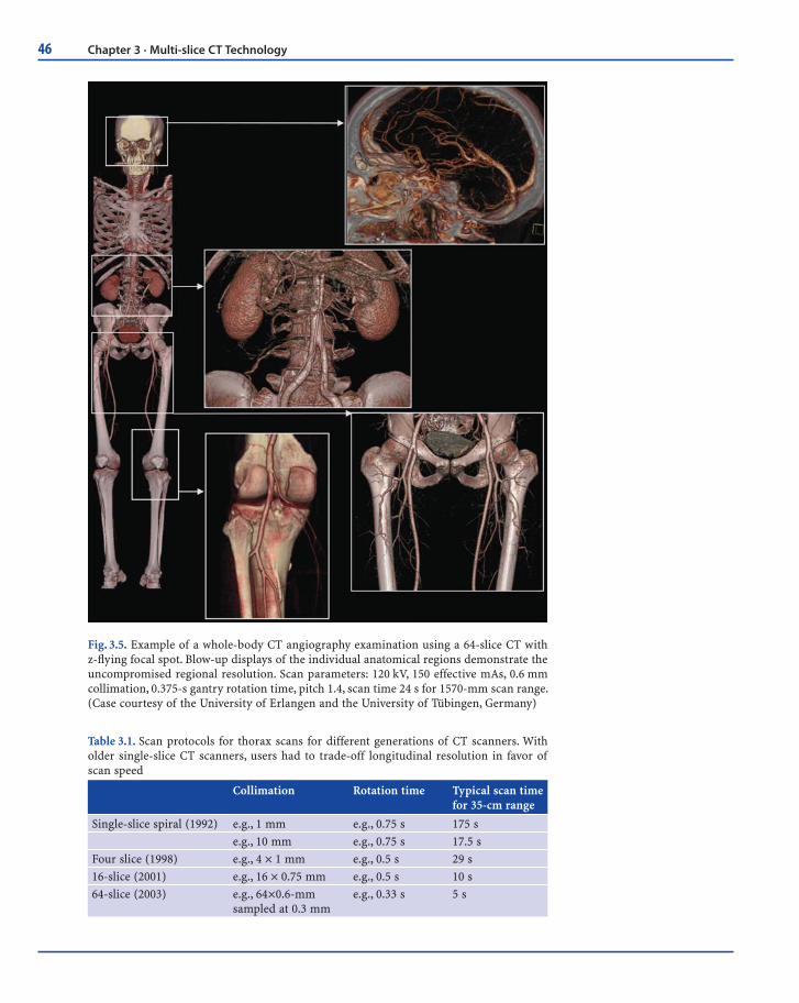
Fig. 3.5. Example of a whole-body CT angiography examination using a 64-slice CT with z-fl ying focal spot. Blow-up displays of the individual anatomical regions demonstrate the uncompromised regional resolution. Scan parameters: 120 kV, 150 effective mAs, 0.6 mm collimation, 0.375-s gantry rotation time, pitch 1.4, scan time 24 s for 1570-mm scan range. (Case courtesy of the University of Erlangen and the University of Tübingen, Germany)
Table 3.1. Scan protocols for thorax scans for different generations of CT scanners. With older single-slice CT scanners, users had to trade-off longitudinal resolution in favor of scan speed
Collimation Rotation time Typical scan time for 35-cm range
Single-slice spiral (1992) e.g., 1 mm e.g., 0.75 s 175 s
e.g., 10 mm e.g., 0.75 s 17.5 s
Four slice (1998) e.g., 4 × 1 mm e.g., 0.5 s 29 s
16-slice (2001) e.g., 16 × 0.75 mm e.g., 0.5 s 10 s
64-slice (2003) e.g., 64×0.6-mm sampled at 0.3 mm
e.g., 0.33 s 5 s

47
projections. Most modern CT scanners use “rebin-ning”, which is an interpolation of the measured fan-beam data to parallel data, since parallel geom-etry simplifies image reconstruction.
The overall performance of a CT system depends on several key components. These include the X-ray source; a high-powered generator, detector, and detector electronics; data transmission systems (slip-rings); and the computer system for image reconstruction and manipulation.
State-of-the-art X-ray tube/generator combina-tions provide a peak power of 60–100 kW, usually at various user-selectable voltages, e. g., 80, 100, 120, and 140 kV. Different clinical applications require different X-ray spectra and hence different kV set-tings for optimum image quality and/or best pos-sible signal-to-noise ratio at the lowest radiation dose. As an example, CT angiographic examinations generally benefit from a lower tube voltage (Schöpf 2003). In a conventional tube design, an anode plate that is typically 160–220 mm in diameter rotates in a vacuum housing (Fig. 3.7a). The heat-storage capac-ity of the anode plate and tube housing – measured in mega heat units (MHU)–determines the perfor-mance level: the bigger the anode plate is, the larger the heat-storage capacity, and the more scan-seconds can be delivered until the anode plate reaches its temperature limit. Typically, a conventional state-of-the-art X-ray tube has a heat-storage capacity of 5–9 MHU, realized by thick graphite layers attached to
1. Continuous data acquisition (the possibility to reconstruct images at any z position)
2. Ability to scan a long range in a short time with-out compromising longitudinal (z) resolution
The first requirement calls for a spiral acquisition. The breakthrough in multi-slice spiral CT brought about in 1998 was due to the fact that it was able to fulfill the second requirement: maximum z resolu-tion is defined by the longitudinal detector pixel size alone rather than by a combination of spiral pitch and detector collimation as in single-slice spiral scanners. Moreover, multi-slice spiral scanners pro-vide the new feature of allowing the z-resolution to be specified in the image-reconstruction step, i.e., after the scan has been done.
The technical challenges of multi-slice CT are manifold: A detector capable of measuring several thousand channels at a time has to be built; the data have to be transferred to the image-reconstruction system, and a suitable reconstruction algorithm has to be provided.
The basic system components of a modern “third-generation” CT system are shown in Figure 2.2. Third-generation CT scanners employ a “rotate/rotate” geometry, in which both the X-ray tube and the detector rotate about the patient (Fig. 2.2d). In a multi-slice CT system, the detector comprises many rows of 700 and more detector elements that cover a scan field of view (SFOV) of usually 50 cm. The X-ray attenuation of the object is measured by the individ-ual detector elements. Each measurement value is characterized by: (1) its projection angle α, i. e., the angular coordinate of the line connecting the center of the detector and the focal spot of the X-ray tube; (2) the fan angle β, i. e., the angle between each indi-vidual detector element and this center-line; and (3) the slice-index m. All measurement values acquired at the same angular position of the measurement system, that is, at the same α, are called a projection of view. Typically, 1000 projections are measured during each 360° rotation. An alternative set of vari-ables characterizing the measurement rays is θ, b, and m, where θ is the azimuthal angle and b denotes the distance of a ray from the iso-center (Fig. 3.6). α and β are used when projection data are in the form of fan-beam projections, θ and b are used to label rays when projection data are in the form of parallel
α θ
βobject
x
y
S
focal spot
ray
b
Fig. 3.6. Defi nition of variables used to characterize the mea-surement rays of a CT scanner. A parallel projection is ob-tained by assembling rays from several fan-beam projections
3.2 · Principles of Multi-slice CT System Design
48 Chapter 3 · Multi-slice CT Technology
Anode
Cooling oil
X-rays
Fig. 3.7. A conventional X-ray tube (a) and a rotating-envelope tube (b). The electrons emitted by the cathode are represented by green lines, the X-rays generated in the anode are depicted as purple arrows. In a conventional X-ray tube, the anode plate rotates in a vacuum housing. Heat is mainly dissipated via thermal radiation. In a rotating-envelope tube, the anode plate con-stitutes an outer wall of the tube housing and is in direct contact with the cooling oil. Heat is effectively dissipated via thermal conduction, and the cooling rate is signifi cantly increased. Rotating-envelope tubes have no moving parts and no bearings in the vacuum
X-rays
Defl ection unit
e-beam
Anode
Cathode
ba
the backside of the anode plate. The heat produced in the anode during X-ray emission is mainly dissipated via thermal radiation, with only a small percent-age released via thermal conduction (Fig. 3.7a). The moderate heat dissipation rates of 0.5–1.8 MHU/min usually limit the rate at which scans can be repeated as well as the maximum available power for each scan. Constructive efforts aim at increasing both the heat-storage capacity and the heat-dissipation rate, e.g., by increasing the anode diameter, using circular grooves in the anode support to increase the contact area for improved cooling, or by employing special liquid-metal vacuum bearings that allow for faster anode rotation. An alternative design is the so-called rotating-envelope tube, as illustrated in Figures 3.7b and 3.8. The anode plate constitutes an outer wall of the rotating tube housing; it is therefore in direct contact with the cooling oil and can be effectively cooled by thermal conduction. In this way, a very high heat-dissipation rate of 5 MHU/min is achieved, eliminating the need for heat storage in the anode, which consequently has a heat-storage capacity close to zero. Due to the rapid cooling of the anode, rotat-ing-envelope tubes can perform high-power scans in rapid succession. With rotating-envelope tubes,
Anodez-axis
Cathode
12 cm
Fig. 3.8. A rotating-envelope X-ray tube (STRATON tube, Sie-mens, Forchheim, Germany). The tube design is very compact; the anode diameter is only 12 cm
up to five full-power 10-s spirals are possible within 100 s (Schardt 2004). Ultimately, the performance of both conventional and rotating-envelope tubes is limited by the maximum heat dissipation of the CT system itself. Since there are no moving parts and no bearings in the vacuum, the tube design can be small and compact (anode diameter 12 cm) so that it

49
has the potential to better withstand the high gravi-tational forces associated with gantry rotation times of < 0.4 s. Due to the central rotating cathode, per-manent electromagnetic deflection of the electron beam is needed to position and shape the focal spot on the anode. Versatile electromagnetic deflection is a prerequisite for the flying focal spot in the z-direc-tion that has been used in most of the recent 64-slice CT-systems.
With the increasing number of detector rows and decreasing gantry rotation times, the data-trans-mission systems of multi-slice CT scanners must be capable of handling significant data rates. A 4-slice CT-system with 0.5-s rotation time roughly generates 1000 × 700 × 4 × 2 Bytes = 5.6 MB of data per rotation, corresponding to 11.2 MB/s; a 16-slice CT-scanner with the same rotation time generates 45 MB/s, and a 64-slice CT-system can produce up to 180–200 MB/s. This stream of data is a challenge for data trans-mission off the rotating part of the gantry and for real-time data processing in the subsequent image-reconstruction systems. In modern CT systems, con-tactless transmission technology is generally used for data transfer; that is, either laser transmission or electromagnetic transmission with coupling between a rotating transmission ring antenna and a station-ary receiving antenna. In the image-reconstruction, computer images are reconstructed at a rate of up to 40 images/s using special array processors.
Modern CT systems generally use solid-state detectors. Each detector element consists of a radia-tion-sensitive solid-state material (such as cad-mium tungstate, gadolinium-oxide, or gadolinium oxisulfide with suitable dopings), which converts the absorbed X-rays into visible light. The light is then detected by a silicon photodiode. The resulting electrical current is amplified and converted into a digital signal. Key requirements for a suitable detec-tor material are good detection efficiency and very short afterglow time to enable the fast gantry rota-tion speeds that are essential for ECG-gated cardiac imaging. Gas detectors, such as the xenon detectors used in previous generations of single-slice CT sys-tems, have meanwhile become obsolete due to their limited detection efficiency.
A CT detector must provide different slice widths to adjust the optimum scan speed, longitudinal res-olution, and image noise for each application. With a single-slice CT detector, different collimated slice widths are obtained by pre-patient collimation of the X-ray beam (Fig. 3.9). Figure 3.9 shows a very elementary model of a 2-slice CT detector consisting of two detector rows generating 2 slices per rotation. Different slice widths are obtained by pre-patient collimation as the detector is separated midway along the z-extent of the X-ray beam.
For acquisition of more than 2 slices per rotation, this simple design principle must be replaced by a more flexible one, in which the number of detector
Focus
Collimator
z-axisScan
-FO
V
Detector
Slice-Width
Fig. 3.9. Pre-patient collimation of the X-ray beam to obtain different colli-mated slice widths with a single-slice CT detector or a dual-slice CT detector
3.2 · Principles of Multi-slice CT System Design

50 Chapter 3 · Multi-slice CT Technology
rows is greater than the number of simultaneously acquired slices. In order to be able to select different slice widths, several detector rows are electronically combined into a smaller number of slices according to the selected beam collimation and the desired slice width.
For the 4-slice CT systems introduced in 1998, two detector types have been commonly used. The fixed array detector consists of detector elements with equal sizes in the longitudinal direction. A represen-tative example for this scanner type has 16 detector rows, each of them defining a collimated slice width in the center of rotation of 1.25 mm (Hu 1999, Hu 2000, McCollough 1999). The total coverage in the longitudinal direction is 20 mm at iso-center; due to geometric magnification, the actual detector is about twice as wide. By pre-patient collimation and combination of the signals of the individual detector rows, the following slice widths (measured at iso-center) are realized: 4 × 1.25, 4 × 2.5, 4 × 3.75, and 4 × 5 mm (Fig. 3.10a). The same detector design can be used for an 8-slice version of this system, with collimated slice widths of 8 × 1.25 and 8 × 2.5 mm.
A different approach uses an adaptive array detector design, which comprises detector rows with different sizes in the longitudinal direction. Scan-ners of this type have eight detector rows that can be combined to yield different slice-collimation set-tings (Klingenbeck 1999, Ohnesorge 1999). Slice widths in the longitudinal direction range from 1 to 5 mm (at iso-center) and allow for the following collimated slice widths: 2 × 0.5, 4 × 1, 4 × 2.5, 4 × 5, 2 × 8, and 2 × 10 mm (Fig. 3.10b).
The selection of the collimated slice width deter-mines the intrinsic longitudinal resolution of a scan. In a ""step-and-shoot"" axial mode, any mul-tiple of the collimated width of one detector slice can be obtained by adding the detector signals during image reconstruction. In a spiral mode, the effective slice width – which is usually defined as the full width at half maximum (FWHM) of the spiral slice sensitivity profile (SSP) – is adjusted independently in the spiral interpolation process during image reconstruction. Hence, from the same data set, both narrow slices for high-resolu-tion detail or 3D post-processing and wide slices for better contrast resolution or quick review and filming may be derived.
The established 16-slice CT systems generally have adaptive array detectors. One representative example for this scanner type uses 24 detector rows (Flohr 2002). The 16 central rows define a 0.75-mm collimated slice width at iso-center; the four outer rows on both sides define a 1.5-mm collimated slice width (Fig. 3.10c). The total coverage in the longitudi-nal direction is 24 mm at iso-center. By appropriate combination of the signals of the individual detector rows, either 12 or 16 slices, each with a collimated slice width of 0.75 mm or 1.5 mm, can be acquired simultaneously. Most commercially available 16-slice CT scanners use similar detector designs, partly with different collimation settings (e.g., 16 × 0.625 mm/16 × 1.25 mm or 16 × 0.5 mm/16 × 1mm/16 × 2 mm collimated slice width).
In 2004, the latest generation of multi-slice CT systems providing more than 16 slices, up to 64 slices per rotation, was introduced. One of the new scanners employs an adaptive array detector with a total of 40 detector rows and a special double z-sam-pling technique that doubles the number of slices acquired per rotation. The 32 central detector rows of this scanner define a 0.6-mm collimated slice width at iso-center; the four outer rows on both sides define a 1-mm collimated slice width (Fig. 3.10d). When all 40 detector rows are illuminated, the total coverage in the longitudinal direction is 28.8 mm. Using a periodic motion of the focal spot in the z-direction (z-flying focal spot), two subsequent 32-slice readings with a collimated slice width of 0.6 mm are slightly shifted in the z-direction and combined to yield one 64-slice projection with a sampling distance of 0.3 mm at iso-center. With this double z-sampling technique, 64 overlapping 0.6-mm slices per rotation are acquired. Alterna-tively, 24 slices, each with a 1.2-mm slice width, can be obtained to provide the full longitudinal detec-tor coverage of 28.8 mm.
Another 40-slice system design provides 40 slices based on an adaptive array detector design with 40 × 0.625-mm or 32 × 1.25-mm collimation, with a coverage of 40 mm at iso-center (Fig. 3.10e). Other recently introduced 64-slice scanners employ fixed array detectors with 64 detector rows, with a thinnest collimated slice width of 0.5–0.625 mm, thus provid-ing a total volume coverage of 32–40 mm (Fig. 3.10f). A direct comparison of the two different 64-slice detec-

51
Scan
-fie
ld
X-ray focus
z-axis
Fixed Array Detector, 16 rows, 4 slices
16 x 1.25
Scan
-fie
ld
X-ray focus
z-axis
Adaptive Array Detector, 8 rows, 4 slices
5 52.5 2.51.5 1.51 1
Scan
-fie
ld
X-ray focus
z-axis
Adaptive Array Detector, 24 rows, 16 slices
4 x 1.5 4 x 1.516 x 0.75
X-ray focus
Scan
-fie
ld
z-axis32 x 0.64 x 1.2 4 x 1.2
Adaptive Array Detector, 40 rows, 32 x 2 slices (z-FFS)
X-ray focus
X-ray focusSc
an-f
ield
Scan
-fie
ld
Adaptive Array Detector, 52 rows, 32 / 40 slices
z-axis40 x 0.625 6 x 1.256 x 1.25
z-axis64 x 0.625
Fixed Array Detector, 64 rows, 64 slices
Fig. 3.10a–f. Examples of fi xed array detectors and adaptive array detectors used in commercially available multi-slice CT systems. a Fixed array detector of a 4- to 8-slice CT scanner, GE LightSpeed Plus and Ultra; b adaptive array detector of a 4-slice CT scanner (Siemens SOMATOM Sensation 4 and Philips MX 8000); c adaptive array detector of a 16-slice CT scanner (Siemens SOMATOM Sensation 16 and Philips MX 8000 IDT); d adaptive array detector of a 64-slice CT scanner employ-ing double z-sampling technique (Siemens SOMATOM Sensation 64); e adaptive array detector of a 40-slice CT scanner (Philips Brilliance 40); f fi xed array detector of a 64-slice CT scanner using 64 detector rows (GE LightSpeed VCT and Philips Brilliance 64)
a
b
c
d
e
f
tor designs with 32 rows and double z-sampling vs. straight 64-row geometry is shown in Figure 3.11a–c. Whereas the straight 64-row concept can acquire four times more volume per rotation with sub-mil-limeter slices than the previous 16-slice CT scan-ners, double z-sampling can still allows the acquisi-tion of two times more volume per rotation but also twice the amount of data per volume. This results in
improved resolution and image quality compared to previous 16-slice CT scanners. Figure 3.11d shows a representative example of a detector module of a 64-slice CT scanner that employs the double z-sampling technique. Each module consists of 40 × 16 detector pixels and the corresponding electronics. The anti-scatter collimators are diagonally cut to open the view of the detector ceramics.
3.2 · Principles of Multi-slice CT System Design

52 Chapter 3 · Multi-slice CT Technology
3.3 Multi-slice CT Acquisition and Reconstruction for Body Imaging
With the advent of multi-slice CT, axial sequential scanning ("step-and-shoot" scanning) has remained in use only for few clinical applications, such as standard head scanning, high-resolution lung scan-ning, perfusion CT, and interventional applications. A detailed theoretical description to predict the per-formance of multi-slice CT in sequential mode can be found in (Hsieh 2001). However, spiral (or "heli-cal") scanning is the method of choice for the vast majority of multi-slice CT examinations.
3.3.1 Defi nition of the Pitch
An important parameter to characterize a spiral/helical scan is the pitch. According to IEC (Interna-tional Electrotechnical Commission 2002) specifica-tions, the pitch is given by:
pitch = table feed per rotation / total width of the collimated beam (3.1)
This definition holds for single-slice CT and for multi-slice CT. It shows whether data acquisi-
X-ray focusSc
an-f
ield
z-axis32 x 0.64 x 1.2 4 x 1.2
X-ray focus
Scan
-fie
ld
z-axis64 x 0.625
2x32 Slices/Rotation64 Channel DAS
0.6 mm
0.6 mm
0.3 mm Oversampling
z
Fig. 3.11. Direct comparison of two different 64-slice detector designs shows that the 32-row design with double z-sampling (a) acquires double the amount of data per volume compared to a straight 64-row geometry (b). The double z-sampling technique with 0.6-mm detector collimation provides data samples at 0.3-mm sam-pling distance in the z-direction (c). A detector module of a 64-slice CT scanner using the double z-sampling technique (Siemens SOMATOM Sensation 64) is shown in (d). Each module consists of 40 × 16 detector pixels with the corresponding electronics. The anti-scatter collimators are diagonally cut to open the view on the detector ceramics (yellow)
a
c
b
d
53
tion occurs with gaps (pitch > 1) or with overlap (pitch < 1) in the longitudinal direction. For a 4-slice CT scanner with 4 × 1-mm collimation and a table-feed of 6 mm per rotation, pitch = 6/(4 × 1) = 6/4=1.5. With 16 × 0.75-mm collimation and a table-feed of 18 mm/rotation, pitch = 18/(16 × 0.75) = 18/12=1.5, too. In the early days of 4-slice CT, the term “detector pitch” was additionally introduced, and it accounts for the width of one single slice in the denominator. For a beam collimation of 4 × 1 mm, the beam consists of four sub-beams, each 1-mm wide at the center of rotation. With 6-mm table-feed per rotation, the detector pitch is pitchvol = 6/1=6. For the sake of clarity, the detector pitch should no longer be used.
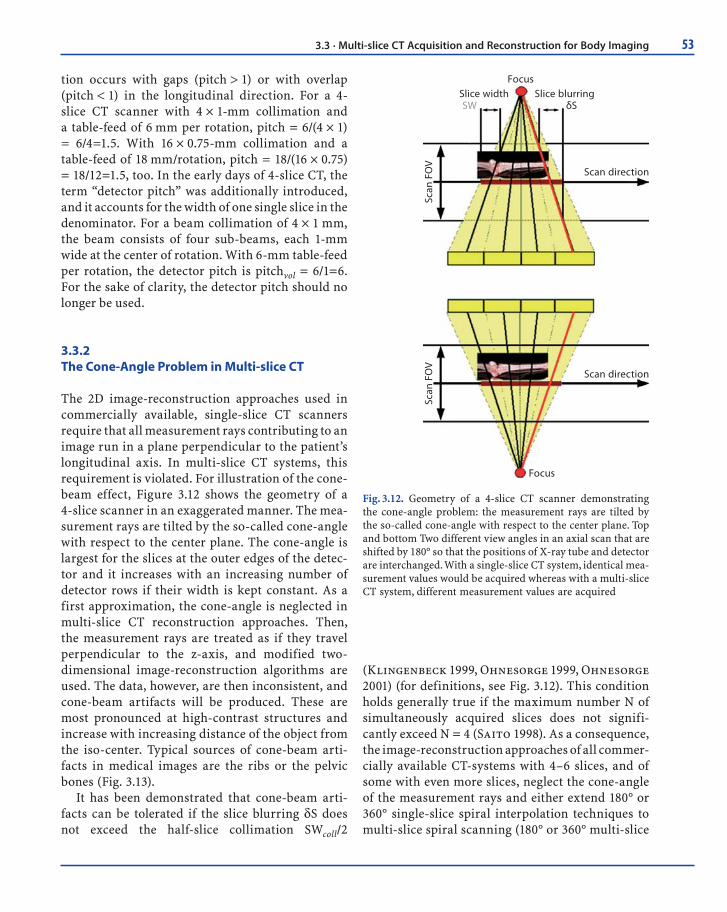
3.3.2The Cone-Angle Problem in Multi-slice CT
The 2D image-reconstruction approaches used in commercially available, single-slice CT scanners require that all measurement rays contributing to an image run in a plane perpendicular to the patient’s longitudinal axis. In multi-slice CT systems, this requirement is violated. For illustration of the cone-beam effect, Figure 3.12 shows the geometry of a 4-slice scanner in an exaggerated manner. The mea-surement rays are tilted by the so-called cone-angle with respect to the center plane. The cone-angle is largest for the slices at the outer edges of the detec-tor and it increases with an increasing number of detector rows if their width is kept constant. As a first approximation, the cone-angle is neglected in multi-slice CT reconstruction approaches. Then, the measurement rays are treated as if they travel perpendicular to the z-axis, and modified two-dimensional image-reconstruction algorithms are used. The data, however, are then inconsistent, and cone-beam artifacts will be produced. These are most pronounced at high-contrast structures and increase with increasing distance of the object from the iso-center. Typical sources of cone-beam arti-facts in medical images are the ribs or the pelvic bones (Fig. 3.13).
It has been demonstrated that cone-beam arti-facts can be tolerated if the slice blurring δS does not exceed the half-slice collimation SWcoll/2
(Klingenbeck 1999, Ohnesorge 1999, Ohnesorge 2001) (for definitions, see Fig. 3.12). This condition holds generally true if the maximum number N of simultaneously acquired slices does not signifi-cantly exceed N = 4 (Saito 1998). As a consequence, the image-reconstruction approaches of all commer-cially available CT-systems with 4–6 slices, and of some with even more slices, neglect the cone-angle of the measurement rays and either extend 180° or 360° single-slice spiral interpolation techniques to multi-slice spiral scanning (180° or 360° multi-slice
Scan
FO
VSc
an F
OV
Scan direction
Scan direction
Focus
FocusSlice width Slice blurringSW δS
Fig. 3.12. Geometry of a 4-slice CT scanner demonstrating the cone-angle problem: the measurement rays are tilted by the so-called cone-angle with respect to the center plane. Top and bottom Two different view angles in an axial scan that are shifted by 180° so that the positions of X-ray tube and detector are interchanged. With a single-slice CT system, identical mea-surement values would be acquired whereas with a multi-slice CT system, different measurement values are acquired
3.3 · Multi-slice CT Acquisition and Reconstruction for Body Imaging
54 Chapter 3 · Multi-slice CT Technology
linear interpolation; see Hu 1999) or they introduce generalized z-filter approaches (Taguchi 1998, Schaller 2000). While these approaches are fully adequate for 4–6 slice CT scanners, they will lead to artifacts and image-quality degradation if applied to spiral scanning with 16 and more slices. In this context, ECG-gated cardiac scanning requires spe-cial attention. The heart is usually sufficiently cen-tered and does not contain extended high-contrast structures that could be the source of cone-beam artifacts. Indeed, adequate results without cone cor-rection are obtained for cardiac scanning with 16 slices; only with 64 slices do cone-beam reconstruc-tion approaches also become mandatory for ECG-gated spiral CT (Flohr 2003) (Fig. 3.14).
3.3.3 Multi-slice Spiral Reconstruction Neglecting the Cone-Beam Geometry
3.3.3.1 180° and 360° Multi-slice Linear Interpolation
The 360° and 180° linear interpolation (LI) single-slice spiral reconstruction approaches can be extended to multi-detector row spiral scanning in a straightforward way (Hu 1999, Schaller 2000, Hsieh 2003). Both 360° and 180° multi-slice linear interpolation (MLI) are characterized by a projec-tion-wise linear interpolation between two rays on either side of the image plane. The cone-angle of
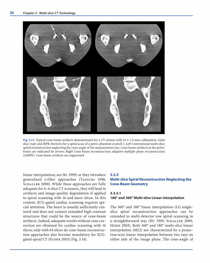
Fig. 3.13. Typical cone-beam artifacts demonstrated for a CT system with 16 × 1.5-mm collimation. Axial slice (top) and MPR (bottom) for a spiral scan of a pelvic phantom at pitch 1. Left Conventional multi-slice spiral reconstruction neglecting the cone-angle of the measurement rays. Cone beam-artifacts at the pelvic bones are indicated by arrows. Right Cone-beam reconstruction adaptive multiple plane reconstruction (AMPR). Cone-beam artifacts are suppressed

55
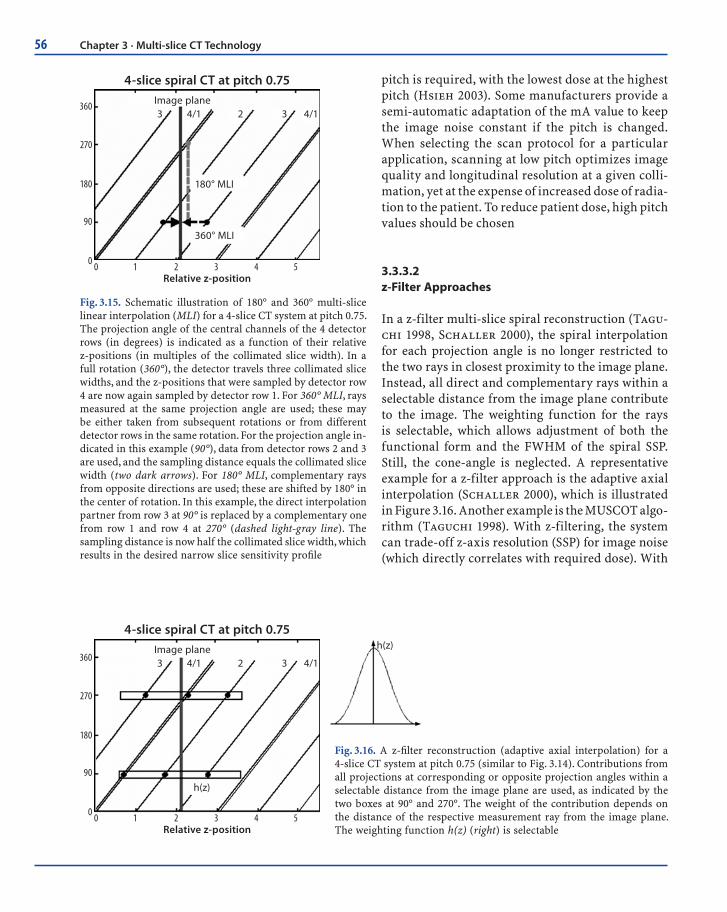
the measurement rays is not taken into account. In the 360° MLI spiral reconstruction approach, either rays measured at the same projection angle by dif-ferent detector rows or rays measured in consecu-tive rotations of the scanner (i.e., 360° apart) are used for spiral interpolation. In the 180° MLI spiral reconstruction approach, both direct and comple-mentary rays are considered. At iso-center, direct and complementary rays interleave in the z-direc-tion for selected pitch values. In this way, the dis-tance between measured samples is significantly reduced and equals half the collimated slice width, SWcoll, which results in the desired narrow SSPs. Appropriate pitch values are 0.75 for 4-slice scan-ning (Hu 1999) and 0.5625 or 0.9375 for 16-slice scanning (Hsieh 2003). Figure 3.15 schematically illustrates 180° and 360° MLI for the example of a 4-slice CT scanner.
In general, scanners relying on 180° or 360° MLI techniques and extensions thereof provide selected
discrete pitch values to the user – such as 0.75 and 1.5 for 4-slice scanning (Hu 1999), or 0.5625, 0.9375, 1.375, and 1.75 for 16-slice scanning (Hsieh 2003). The user has to be aware of pitch-dependent effec-tive slice widths (s). For low-pitch scanning (at pitch = 0.75 using 4 slices and at pitch = 0.5625 or 0.9375 using 16 slices), SW ~ SWcoll, and for a collimated 1.25-mm slice the resulting effective slice width stays at 1.25 mm. The narrow SSP, however, is achieved by a 180° MLI reconstruction using conjugate inter-polation at the price of increased image noise (Hu 1999, Hsieh 2003). For high-pitch scanning (at p = 1.5 using 4 slices and at pitch = 1.375 or 1.75 using 16 slices), SW ~ 1.27SWcoll, and a collimated 1.25-mm slice results in an effective 1.5- to 1.6-mm slice. When comparing dose and image noise for differ-ent pitch values, widening of the SSP has to be taken into account. To obtain the same image noise as in an axial scan with the same collimated slice width, 0.73–1.68 times the dose depending on the spiral
4 x 1 mm 16 x 0.75 mm
32 x 0.75 mm 64 x 0.75 mm
Fig. 3.14. Cone-beam artifacts in cardiac CT. MPRs along the left anterior descending (LAD) coronary artery of an anthropomorphic heart phantom for virtual scanner geometries with collimations of 4 × 1, 16 × 0.75, 32 × 0.75, and 64 × 0.75 mm. ECG-gated reconstruction neglecting the cone-angle of the mea-surement rays. Deviating from general radiology applications, the MPRs show no signifi cant cone-beam artifacts for up to 16 slices. For 32 slices, the MPRs begin to suffer from such artifacts; see the stents in the LAD. For 64 slices, MPRs show severe cone-beam artifacts
3.3 · Multi-slice CT Acquisition and Reconstruction for Body Imaging
56 Chapter 3 · Multi-slice CT Technology
pitch is required, with the lowest dose at the highest pitch (Hsieh 2003). Some manufacturers provide a semi-automatic adaptation of the mA value to keep the image noise constant if the pitch is changed. When selecting the scan protocol for a particular application, scanning at low pitch optimizes image quality and longitudinal resolution at a given colli-mation, yet at the expense of increased dose of radia-tion to the patient. To reduce patient dose, high pitch values should be chosen
3.3.3.2 z-Filter Approaches
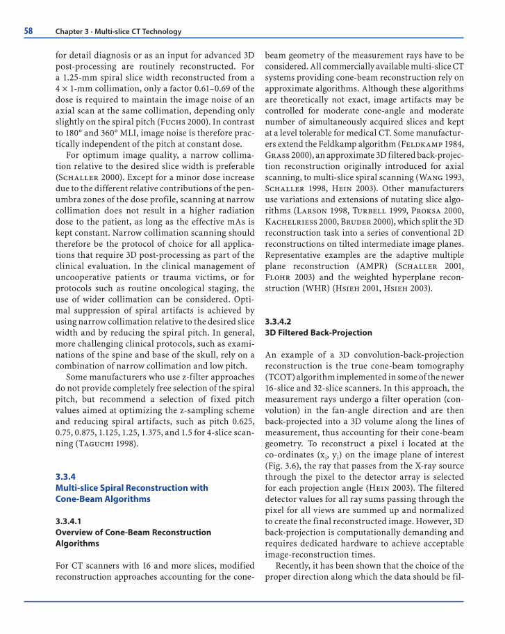
In a z-filter multi-slice spiral reconstruction (Tagu-chi 1998, Schaller 2000), the spiral interpolation for each projection angle is no longer restricted to the two rays in closest proximity to the image plane. Instead, all direct and complementary rays within a selectable distance from the image plane contribute to the image. The weighting function for the rays is selectable, which allows adjustment of both the functional form and the FWHM of the spiral SSP. Still, the cone-angle is neglected. A representative example for a z-filter approach is the adaptive axial interpolation (Schaller 2000), which is illustrated in Figure 3.16. Another example is the MUSCOT algo-rithm (Taguchi 1998). With z-filtering, the system can trade-off z-axis resolution (SSP) for image noise (which directly correlates with required dose). With
4-slice spiral CT at pitch 0.75
0 1 2 3 4 50
90
180
270
360
Relative z-position
Image plane
360° MLI
180° MLI
3 4/1 2 3 4/1
Fig. 3.15. Schematic illustration of 180° and 360° multi-slice linear interpolation (MLI) for a 4-slice CT system at pitch 0.75. The projection angle of the central channels of the 4 detector rows (in degrees) is indicated as a function of their relative z-positions (in multiples of the collimated slice width). In a full rotation (360°), the detector travels three collimated slice widths, and the z-positions that were sampled by detector row 4 are now again sampled by detector row 1. For 360° MLI, rays measured at the same projection angle are used; these may be either taken from subsequent rotations or from different detector rows in the same rotation. For the projection angle in-dicated in this example (90°), data from detector rows 2 and 3 are used, and the sampling distance equals the collimated slice width (two dark arrows). For 180° MLI, complementary rays from opposite directions are used; these are shifted by 180° in the center of rotation. In this example, the direct interpolation partner from row 3 at 90° is replaced by a complementary one from row 1 and row 4 at 270° (dashed light-gray line). The sampling distance is now half the collimated slice width, which results in the desired narrow slice sensitivity profi le
4-slice spiral CT at pitch 0.75
0 1 2 3 4 50
90
180
270
360
Relative z-position
Image plane
h(z)
3 4/1 2 3 4/1
h(z)
Fig. 3.16. A z-fi lter reconstruction (adaptive axial interpolation) for a 4-slice CT system at pitch 0.75 (similar to Fig. 3.14). Contributions from all projections at corresponding or opposite projection angles within a selectable distance from the image plane are used, as indicated by the two boxes at 90° and 270°. The weight of the contribution depends on the distance of the respective measurement ray from the image plane. The weighting function h(z) (right) is selectable

57
the adaptive axial interpolation, the spiral pitch is freely selectable in the range 0.5–2.0, and the same effective slice width, defined as the FWHM of the spiral SSP, is generated at all pitch values (Klingenbeck 1999, Schaller 2000, Fuchs 2000). Therefore, longitudinal resolution is independent of the pitch, deviating from single-slice spiral CT and from multi-slice CT relying on 180°and 360°MLI (Hu 1999, Hsieh 2003). Figure 3.17 shows the SSPs of the 2-mm slice (for 4 × 1-mm collimation) and MPRs of a spiral z-resolution phantom for selected pitch values. As a consequence of the pitch-independent spiral slice width, the image noise for fixed mA (fixed tube current) would decrease with decreasing pitch due to the increasingly overlapping spiral acquisition. Instead, the user selects an “effective” mAs value, and the tube current (mA) is then automatically adapted to the pitch of the spiral scan to compensate for dose accumulation. The dose for fixed effective
mAs is independent of the spiral pitch and equals the dose of an axial scan with the same mAs.
In conclusion, when using z-filter multi-slice spiral reconstruction approaches, changing the pitch in multi-slice CT does not change the radiation dose to the patient, which is not the case in single-slice spiral CT. Accordingly, using higher pitch in multi-slice CT does not result in dose reduction, which is an important practical consideration with CT systems, in particular those applying adaptive axial interpolation reconstruction algorithms.
The intrinsic resolution of a multi-slice spiral CT scan is determined by the choice of collimation, e.g., 4 × 1 or 4 × 2.5-mm. With z-filtering, retrospective reconstruction of images with different slice widths from the same CT raw data set is possible. Only slice widths equal to or larger than the collimation of one slice can be obtained. In many cases, both thick slices for initial viewing and filming and thin slices
Pitch 7/4d = 2.1 mm
0
0.2
0.8
0.4
0.6
1.0
0-2-4 42
Pitch 3/4Measured d = 2.05 mm
0
0.2
0.8
0.4
0.6
1.0
0-2-4 42
Pitch 5/4d = 2.1 mm
0
0.2
0.8
0.4
0.6
1.0
0-2-4 42
calculated measuredz-Axis
Pitch 7/4Pitch 3/4
Clear Separation
Pitch 5/4
z-A
xis
Clear Separation
Clear Separation
bottom
top
Fig. 3.17. Adaptive axial interpolation for a 4-slice CT-system. Top Slice sensitivity profi les (SSPs) of the 2-mm slice (for 4 × 1-mm collimation) at selected pitch values. The functional forms of the SSPs, and hence the slice widths, are independent of the pitch. Bottom MPRs of a spiral z-resolution phantom scanned with 2-mm slice width show clear separation of the 1.5- and 2-mm cylinders for all pitch values as a consequence of the pitch-independent SSPs
3.3 · Multi-slice CT Acquisition and Reconstruction for Body Imaging
58 Chapter 3 · Multi-slice CT Technology
for detail diagnosis or as an input for advanced 3D post-processing are routinely reconstructed. For a 1.25-mm spiral slice width reconstructed from a 4 × 1-mm collimation, only a factor 0.61–0.69 of the dose is required to maintain the image noise of an axial scan at the same collimation, depending only slightly on the spiral pitch (Fuchs 2000). In contrast to 180° and 360° MLI, image noise is therefore prac-tically independent of the pitch at constant dose.
For optimum image quality, a narrow collima-tion relative to the desired slice width is preferable (Schaller 2000). Except for a minor dose increase due to the different relative contributions of the pen-umbra zones of the dose profile, scanning at narrow collimation does not result in a higher radiation dose to the patient, as long as the effective mAs is kept constant. Narrow collimation scanning should therefore be the protocol of choice for all applica-tions that require 3D post-processing as part of the clinical evaluation. In the clinical management of uncooperative patients or trauma victims, or for protocols such as routine oncological staging, the use of wider collimation can be considered. Opti-mal suppression of spiral artifacts is achieved by using narrow collimation relative to the desired slice width and by reducing the spiral pitch. In general, more challenging clinical protocols, such as exami-nations of the spine and base of the skull, rely on a combination of narrow collimation and low pitch.
Some manufacturers who use z-filter approaches do not provide completely free selection of the spiral pitch, but recommend a selection of fixed pitch values aimed at optimizing the z-sampling scheme and reducing spiral artifacts, such as pitch 0.625, 0.75, 0.875, 1.125, 1.25, 1.375, and 1.5 for 4-slice scan-ning (Taguchi 1998).
3.3.4 Multi-slice Spiral Reconstruction with Cone-Beam Algorithms
3.3.4.1 Overview of Cone-Beam Reconstruction Algorithms
For CT scanners with 16 and more slices, modified reconstruction approaches accounting for the cone-
beam geometry of the measurement rays have to be considered. All commercially available multi-slice CT systems providing cone-beam reconstruction rely on approximate algorithms. Although these algorithms are theoretically not exact, image artifacts may be controlled for moderate cone-angle and moderate number of simultaneously acquired slices and kept at a level tolerable for medical CT. Some manufactur-ers extend the Feldkamp algorithm (Feldkamp 1984, Grass 2000), an approximate 3D filtered back-projec-tion reconstruction originally introduced for axial scanning, to multi-slice spiral scanning (Wang 1993, Schaller 1998, Hein 2003). Other manufacturers use variations and extensions of nutating slice algo-rithms (Larson 1998, Turbell 1999, Proksa 2000, Kachelrieß 2000, Bruder 2000), which split the 3D reconstruction task into a series of conventional 2D reconstructions on tilted intermediate image planes. Representative examples are the adaptive multiple plane reconstruction (AMPR) (Schaller 2001, Flohr 2003) and the weighted hyperplane recon-struction (WHR) (Hsieh 2001, Hsieh 2003).
3.3.4.2 3D Filtered Back-Projection
An example of a 3D convolution-back-projection reconstruction is the true cone-beam tomography (TCOT) algorithm implemented in some of the newer 16-slice and 32-slice scanners. In this approach, the measurement rays undergo a filter operation (con-volution) in the fan-angle direction and are then back-projected into a 3D volume along the lines of measurement, thus accounting for their cone-beam geometry. To reconstruct a pixel i located at the co-ordinates (xi, yi) on the image plane of interest (Fig. 3.6), the ray that passes from the X-ray source through the pixel to the detector array is selected for each projection angle (Hein 2003). The filtered detector values for all ray sums passing through the pixel for all views are summed up and normalized to create the final reconstructed image. However, 3D back-projection is computationally demanding and requires dedicated hardware to achieve acceptable image-reconstruction times.
Recently, it has been shown that the choice of the proper direction along which the data should be fil-

59
tered is of critical importance for the image quality achieved with 3D filtered back-projection (Stier-storfer 2004). If the fan-beam projections are fil-tered along the fan-angle direction β, as proposed in the original Wang algorithm (Wang 1993), severe artifacts appear for larger cone angles. Filtering of the data in the direction of the spiral tangent can markedly improve image quality. A good approxi-mation is filtering of the data in the p-direction after rebinning to parallel geometry.
3.3.4.3 Adaptive Multiple Plane Reconstruction
The AMPR-approach (Schaller 2001, Flohr 2003) is an extension and generalization of advanced single-slice rebinning (ASSR) (Larson 1998, Kachelrieß 2000). AMPR allows for free selection of the spiral pitch with optimized dose utilization, which is ben-eficial for medical applications. With ASSR, a partial scan interval (~ 240° of scan data) is used for image reconstruction. The image planes are no longer per-pendicular to the patient axis; instead, they are tilted to match the spiral path of the focal spot (Fig. 3.18a).
For every view angle in this partial scan interval, the focal spot is positioned in or nearby the image plane, i.e., measurement rays running in or very close to the image plane are available. These conditions need to be fulfilled for a standard 2D reconstruction. In a final z-reformation step, the traditional axial images are calculated by an interpolation between the tilted original image planes. ASSR encounters its limita-tions when the spiral pitch is reduced to make use of the overlapping spiral acquisition and the result-ing dose accumulation When a range of projection angles much larger than π (in parallel geometry) for an image are used, it becomes impossible to opti-mally fit the image plane to the spiral path. The AMPR algorithm (Schaller 2001, Flohr 2003) addresses this problem: instead of using all available data for one single image, the data are distributed to several partial images on double-oblique image planes, which are individually adapted to the spiral path and fan out like the pages of a book (Fig. 3.18b). To ensure full use of the dose, both the number of partial images (the number of "pages" in the book) and the length of the data interval per image depend on the spiral pitch (Fig. 3.19a). The final axial (or arbitrarily oriented) images are calculated by a z-
20
15
10
5
0
-5
-101000
0
-1000-600 -400 -200 2000 400 600
20
15
10
5
0
-5
-101000
0
-1000-600 -400 -200 2000 400 600
Fig. 3.18. The advanced single-slice rebinning (ASSR) (a) and AMPR (b) approaches. a In the ASSR approach, the image plane is attached to the focus at reference projection angle θr = 0 (left side). It is tilted by an angle γ around the x-axis. A parallel projection at projection angle θ = π/2 is indicated. The dots represent the focus positions for selected rays within this parallel projection. The reconstruction plane optimally fi ts the spiral path in a projection angle range [-π/2 , π/2]. b The AMPR approach for a 16 slice detector at pitch = 0.75 using the same perspective as in a. Three double-oblique image planes are attached to the focus at reference projection angle θr = 0 (left side). The three image planes fan out like the pages of a book. A parallel projec-tion at projection angle θ = π/2 is indicated
a b
3.3 · Multi-slice CT Acquisition and Reconstruction for Body Imaging

60 Chapter 3 · Multi-slice CT Technology
interpolation between the tilted partial image planes (Fig. 3.19b). The shape and the width of the z-inter-polation functions are selectable. Different SSPs and different slice widths can therefore be adjusted, so that z-axis resolution (SSP) can be traded off with image noise. The spiral pitch is freely selectable and slice width, and consequently z-axis resolution, are independent of the pitch. The concepts of effective mAs and automatic adaptation of the tube current to the pitch also apply to AMPR.
With the AMPR approach, good image quality is obtained for all pitch values between 0.5 and 1.5 (Flohr 2002). Figure 3.20 shows an axial slice and a MPR of an anthropomorphic thorax phantom. Scan data for 16 × 0.75-mm collimation at pitch 1 was reconstructed with 1-mm slice width, using z-filter-ing (top), the AMPR algorithm (center), and 3D back-projection (bottom). If the cone-angle is neglected, artifacts are created for high-contrast objects and geometric distortions occur, particularly in MPRs (top). Both AMPR (center) and 3D back-projection (bottom) restore the spatial integrity of high-con-trast objects, reduce cone-beam artifacts, and are fully equivalent for 16-slice scanning. Recent studies
have demonstrated the adequacy of extended ver-sions of AMPR for medical CT systems with up to 64 rows (Stierstorfer 2002). The remaining artifacts shown in Figure 3.20 are spiral interpolation artifacts (“windmill” artifacts), as opposed to cone-beam arti-facts. Windmill artifacts are not related to the cone-beam geometry but result from the finite width of the detector rows, which thus requires interpolation between them for image reconstruction. Hence, they occur independently of the reconstruction approach. They are exaggerated in the mathematical phantom shown and can be reduced by either decreasing the pitch and/or increasing the reconstruction slice width relative to the collimation.
Multi-slice spiral scanning using AMPR is char-acterized by the same key properties as adaptive axial interpolation, as discussed above for z-filter reconstruction. Thus, all recommendations regard-ing the selection of collimation and pitch that were discussed above also apply for AMPR. In particular, changing the pitch does not change the radiation exposure to the patient, and using higher pitch does not result in dose saving. Narrow collimation scan-ning should be performed whenever possible.
Fig. 3.19a, b. Adaptive multiple plane reconstruction AMPR. a Multi-slice spiral data are divided into over-lapping pitch-dependent segments. As an intermediate step for each of these segments, partial images are reconstructed on double-oblique image planes that are adapted to the local curvature of the spiral and open like the pages of a book. b The resulting images on axial planes are generated via z-reformatting, similar to MPR post-processing
a b

61
Fig. 3.20. Axial slice and MPR of an anthropomorphic thorax phantom. Scan data for 16 × 0.75-mm collimation at pitch 1 was reconstructed with 1-mm slice width and z-fi ltering, neglecting the cone-angle of the measurement rays (top), with the AMPR algorithm (center), and with 3D back-projection with optimized fi lter direc-tion (bottom). Neglecting the cone-angle leads to artifacts for high-contrast objects, particularly in MPRs (top). Both AMPR (center) and 3D back-projection (bottom) reduce cone-beam artifacts and are fully equivalent for 16-slice scanning
3.3.4.4 Weighted Hyperplane Reconstruction
The concepts used in WHR, (described in Hsieh 2001, Hsieh 2003) are related to those used in AMPR, yet are derived in a different way. Similar to AMPR, 3D reconstruction is split into a series of 2D recon-structions. Instead of reconstructing traditional axial slices, convex hyper planes are proposed as the region of reconstruction. The increasing spiral overlap with decreasing pitch is handled by intro-ducing subsets of detector rows, which are sufficient
to reconstruct an image at a given pitch value. At pitch = 0.5625 with a 16-slice scanner, the data col-lected by detector rows 1–9 form a complete projec-tion data set. Similarly, projections from detector rows 2–10 can be used to reconstruct another image at the same z-position; projections from detector rows 3–11 yield a third image, and so on. In a way, these “sub-images” are related to the “book pages” of AMPR. The final image is based on a weighted average of the sub-images. In Hsieh (2003), good image quality for a 16-slice CT system is demon-strated using the WHR approach.
3.3 · Multi-slice CT Acquisition and Reconstruction for Body Imaging
62 Chapter 3 · Multi-slice CT Technology
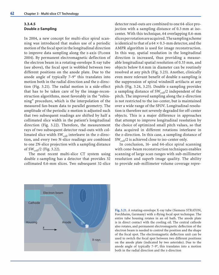
3.3.4.5 Double z-Sampling
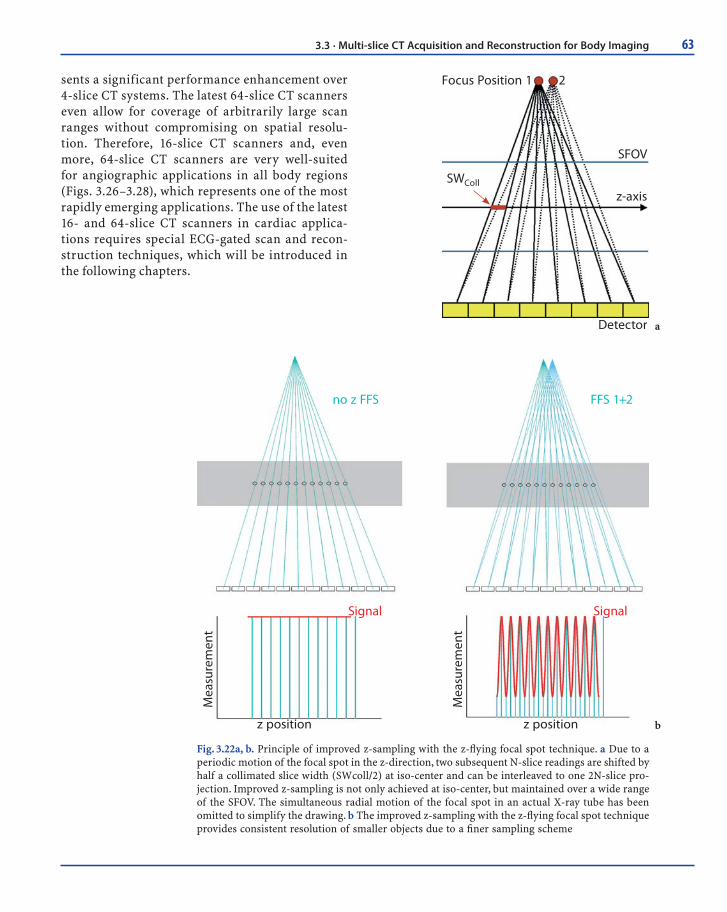
In 2004, a new concept for multi-slice spiral scan-ning was introduced that makes use of a periodic motion of the focal spot in the longitudinal direction to improve data sampling along the z-axis (Flohr 2004). By permanent electromagnetic deflection of the electron beam in a rotating-envelope X-ray tube (see above), the focal spot is wobbled between two different positions on the anode plate. Due to the anode angle of typically 7–9° this translates into motion both in the radial direction and the z-direc-tion (Fig. 3.21). The radial motion is a side-effect that has to be taken care of by the image-recon-struction algorithms, most favorably in the “rebin-ning” procedure, which is the interpolation of the measured fan-beam data to parallel geometry. The amplitude of the periodic z-motion is adjusted such that two subsequent readings are shifted by half a collimated slice width in the patient’s longitudinal direction (Fig. 3.22). Therefore, the measurement rays of two subsequent detector read-outs with col-limated slice width SWcoll interleave in the z-direc-tion, and every two N-slice readings are combined to one 2N-slice projection with a sampling distance of SWcoll/2 (Fig. 3.22).
The most recent multi-slice CT system using double z-sampling has a detector that provides 32 collimated 0.6-mm slices. Two subsequent 32-slice
detector read-outs are combined to one 64-slice pro-jection with a sampling distance of 0.3 mm at iso-center. With this technique, 64 overlapping 0.6-mm slices per rotation are acquired. The sampling scheme is identical to that of a 64 × 0.3-mm detector, and the AMPR algorithm is used for image reconstruction. In this way, spatial resolution in the longitudinal direction is increased, thus providing a measur-able longitudinal spatial resolution of 0.33 mm, and objects below 0.4 mm in diameter can be routinely resolved at any pitch (Fig. 3.23). Another, clinically even more relevant benefit of double z-sampling is the suppression of spiral windmill artifacts at any pitch (Fig. 3.24, 3.25). Double z-sampling provides a sampling distance of SWcoll/2 independent of the pitch. The improved sampling along the z-direction is not restricted to the iso-center, but is maintained over a wide range of the SFOV. Longitudinal resolu-tion is therefore not severely degraded for off-center objects. This is a major difference in approaches that attempt to improve longitudinal resolution by the choice of optimized small pitch values, so that data acquired in different rotations interleave in the z-direction. In this case, a sampling distance of SWcoll/2 is achieved close to iso-center only.
In conclusion, 16- and 64-slice spiral scanning with cone-beam reconstruction techniques enables scanning of large scan ranges with sub-millimeter resolution and superb image quality. The ability to provide sub-millimeter volume coverage repre-
Electron beam
Cathode
Housing Anode
X-rays
z
Fig. 3.21. A rotating-envelope X-ray tube (Siemens STRATON, Forchheim, Germany) with z-fl ying focal spot technique. The entire tube housing rotates in an oil bath. The anode plate is in direct contact with the cooling oil. The central cathode also rotates, and permanent electromagnetic defl ection of the electron beam is needed to control the position and the shape of the focal spot. The electromagnetic defl ection unit can be used to switch the focal spot between two different positions on the anode plate (indicated by two asterisks). Due to the anode angle of typically 7–9°, this translates into a motion both in the radial direction and the z-direction
63
Focus Position 1 2
SWColl
SFOV
z-axis
Detector
no z FFS FFS 1+2
Signal Signal
z positionz position
Mea
sure
men
t
Mea
sure
men
t
Fig. 3.22a, b. Principle of improved z-sampling with the z-fl ying focal spot technique. a Due to a periodic motion of the focal spot in the z-direction, two subsequent N-slice readings are shifted by half a collimated slice width (SWcoll/2) at iso-center and can be interleaved to one 2N-slice pro-jection. Improved z-sampling is not only achieved at iso-center, but maintained over a wide range of the SFOV. The simultaneous radial motion of the focal spot in an actual X-ray tube has been omitted to simplify the drawing. b The improved z-sampling with the z-fl ying focal spot technique provides consistent resolution of smaller objects due to a fi ner sampling scheme
b
a
sents a significant performance enhancement over 4-slice CT systems. The latest 64-slice CT scanners even allow for coverage of arbitrarily large scan ranges without compromising on spatial resolu-tion. Therefore, 16-slice CT scanners and, even more, 64-slice CT scanners are very well-suited for angiographic applications in all body regions (Figs. 3.26–3.28), which represents one of the most rapidly emerging applications. The use of the latest 16- and 64-slice CT scanners in cardiac applica-tions requires special ECG-gated scan and recon-struction techniques, which will be introduced in the following chapters.
3.3 · Multi-slice CT Acquisition and Reconstruction for Body Imaging
64 Chapter 3 · Multi-slice CT Technology
0.33 mmz-
Axi
s
0.36 mm
0.38 mm
0.42 mm
Pitch 0.55 Pitch 0.95 Pitch 1.45
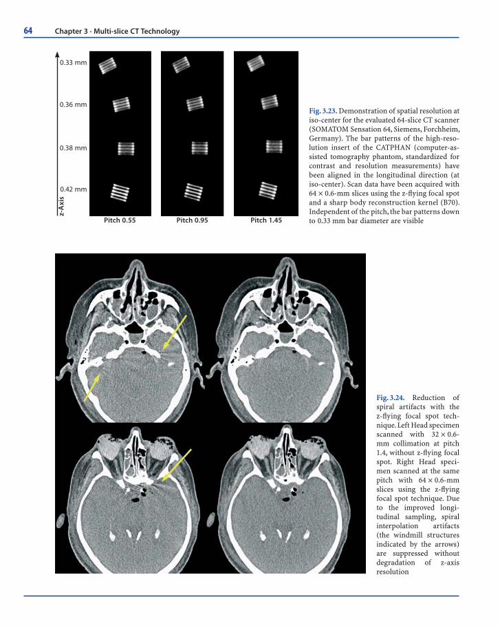
Fig. 3.23. Demonstration of spatial resolution at iso-center for the evaluated 64-slice CT scanner (SOMATOM Sensation 64, Siemens, Forchheim, Germany). The bar patterns of the high-reso-lution insert of the CATPHAN (computer-as-sisted tomography phantom, standardized for contrast and resolution measurements) have been aligned in the longitudinal direction (at iso-center). Scan data have been acquired with 64 × 0.6-mm slices using the z-fl ying focal spot and a sharp body reconstruction kernel (B70). Independent of the pitch, the bar patterns down to 0.33 mm bar diameter are visible
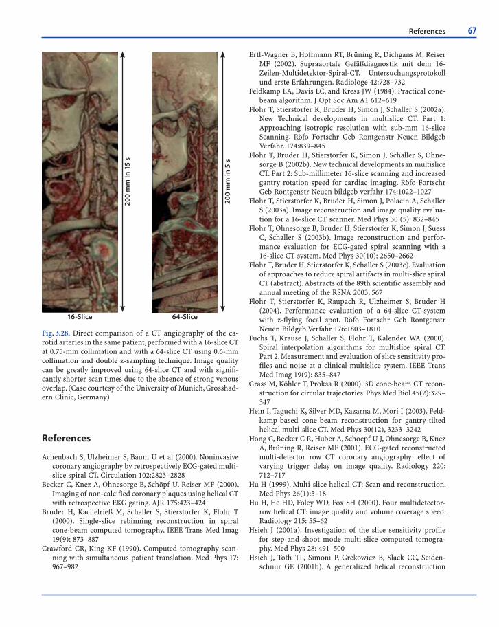
Fig. 3.24. Reduction of spiral artifacts with the z-fl ying focal spot tech-nique. Left Head specimen scanned with 32 × 0.6-mm collimation at pitch 1.4, without z-fl ying focal spot. Right Head speci-men scanned at the same pitch with 64 × 0.6-mm slices using the z-fl ying focal spot technique. Due to the improved longi-tudinal sampling, spiral interpolation artifacts (the windmill structures indicated by the arrows) are suppressed without degradation of z-axis resolution

65
Fig. 3.25. Reduction of spiral artifacts with the z-fl ying focal spot technique. Left Axial slice at the level of the shoulder scanned with 32 × 0.6-mm collimation at pitch 1.4, without z-fl ying focal spot. Right The same patient and the same z-position scanned with the same pitch with 64 × 0.6-mm slices using the z-fl ying focal spot technique. Due to the improved longitudinal sampling, spiral interpolation artifacts that appear as pronounced streaks propagating from left to right are suppressed without degrada-tion of z-axis resolution
Fig. 3.26a–e. Case examples of 16-slice CT angiography examinations using a CT scanner with 16 × 0.75-mm collimation. High-resolution CT angiography of the aorta and iliac arteries with a 1200-mm scan range, visualized in an angiographic-type maximum intensity projections (MIP) display (a) and volume-rendering technique (b). CT angiography examinations of the digital arteries (c), the carotid arteries with an inserted stent (d), and the cerebral vessels (e). (Case courtesy of a, b the University of Tübingen, Germany, and c–e the University of Munich, Grosshadern Clinic, Germany)
b
da
c
e
3.3 · Multi-slice CT Acquisition and Reconstruction for Body Imaging

66 Chapter 3 · Multi-slice CT Technology
Fig. 3.27a–f. Case examples of 64-slice CT angiography examinations using a CT scanner with 0.6-mm collimation and double z-sampling technique. Whole-body CT angiography examination with 0.4-mm resolution and 1570-mm scan range (a). Pure arterial-phase carotid artery examination in 5-s scan time (b). CT angiography of a dissection of the abdominal aorta with excellent visualization of calcifi cations and small-caliber abdominal vessels (c). Detection of pulmonary embolism in a patient with chest pain within a breath-hold time of 5 s (d). CT angiography of the mesenteric arteries in a patient with acute bowel ischemia (e). Display of small vessels with calibers of < 1 mm originating from the thoracic aorta perpendicular to the scan axis (f). (Cases courtesy of the University of Erlangen, Germany)
b
d
fa
c
e
67
Fig. 3.28. Direct comparison of a CT angiography of the ca-rotid arteries in the same patient, performed with a 16-slice CT at 0.75-mm collimation and with a 64-slice CT using 0.6-mm collimation and double z-sampling technique. Image quality can be greatly improved using 64-slice CT and with signifi -cantly shorter scan times due to the absence of strong venous overlap. (Case courtesy of the University of Munich, Grosshad-ern Clinic, Germany)
200
mm
in 1
5 s
16-Slice
200
mm
in 5
s
64-Slice
References
Achenbach S, Ulzheimer S, Baum U et al (2000). Noninvasive coronary angiography by retrospectively ECG-gated multi-slice spiral CT. Circulation 102:2823–2828
Becker C, Knez A, Ohnesorge B, Schöpf U, Reiser MF (2000). Imaging of non-calcified coronary plaques using helical CT with retrospective EKG gating. AJR 175:423–424
Bruder H, Kachelrieß M, Schaller S, Stierstorfer K, Flohr T (2000). Single-slice rebinning reconstruction in spiral cone-beam computed tomography. IEEE Trans Med Imag 19(9): 873–887
Crawford CR, King KF (1990). Computed tomography scan-ning with simultaneous patient translation. Med Phys 17: 967–982
Ertl-Wagner B, Hoffmann RT, Brüning R, Dichgans M, Reiser MF (2002). Supraaortale Gefäßdiagnostik mit dem 16-Zeilen-Multidetektor-Spiral-CT. Untersuchungsprotokoll und erste Erfahrungen. Radiologe 42:728–732
Feldkamp LA, Davis LC, and Kress JW (1984). Practical cone-beam algorithm. J Opt Soc Am A1 612–619
Flohr T, Stierstorfer K, Bruder H, Simon J, Schaller S (2002a). New Technical developments in multislice CT. Part 1: Approaching isotropic resolution with sub-mm 16-slice Scanning, Röfo Fortschr Geb Rontgenstr Neuen Bildgeb Verfahr. 174:839–845
Flohr T, Bruder H, Stierstorfer K, Simon J, Schaller S, Ohne-sorge B (2002b). New technical developments in multislice CT. Part 2: Sub-millimeter 16-slice scanning and increased gantry rotation speed for cardiac imaging. Röfo Fortschr Geb Rontgenstr Neuen bildgeb verfahr 174:1022–1027
Flohr T, Stierstorfer K, Bruder H, Simon J, Polacin A, Schaller S (2003a). Image reconstruction and image quality evalua-tion for a 16-slice CT scanner. Med Phys 30 (5): 832–845
Flohr T, Ohnesorge B, Bruder H, Stierstorfer K, Simon J, Suess C, Schaller S (2003b). Image reconstruction and perfor-mance evaluation for ECG-gated spiral scanning with a 16-slice CT system. Med Phys 30(10): 2650–2662
Flohr T, Bruder H, Stierstorfer K, Schaller S (2003c). Evaluation of approaches to reduce spiral artifacts in multi-slice spiral CT (abstract). Abstracts of the 89th scientific assembly and annual meeting of the RSNA 2003, 567
Flohr T, Stierstorfer K, Raupach R, Ulzheimer S, Bruder H (2004). Performance evaluation of a 64-slice CT-system with z-flying focal spot. Röfo Fortschr Geb Rontgenstr Neuen Bildgeb Verfahr 176:1803–1810
Fuchs T, Krause J, Schaller S, Flohr T, Kalender WA (2000). Spiral interpolation algorithms for multislice spiral CT. Part 2. Measurement and evaluation of slice sensitivity pro-files and noise at a clinical multislice system. IEEE Trans Med Imag 19(9): 835–847
Grass M, Köhler T, Proksa R (2000). 3D cone-beam CT recon-struction for circular trajectories. Phys Med Biol 45(2):329–347
Hein I, Taguchi K, Silver MD, Kazarna M, Mori I (2003). Feld-kamp-based cone-beam reconstruction for gantry-tilted helical multi-slice CT. Med Phys 30(12), 3233–3242
Hong C, Becker C R, Huber A, Schoepf U J, Ohnesorge B, Knez A, Brüning R, Reiser MF (2001). ECG-gated reconstructed multi-detector row CT coronary angiography: effect of varying trigger delay on image quality. Radiology 220: 712–717
Hu H (1999). Multi-slice helical CT: Scan and reconstruction. Med Phys 26(1):5–18
Hu H, He HD, Foley WD, Fox SH (2000). Four multidetector-row helical CT: image quality and volume coverage speed. Radiology 215: 55–62
Hsieh J (2001a). Investigation of the slice sensitivity profile for step-and-shoot mode multi-slice computed tomogra-phy. Med Phys 28: 491–500
Hsieh J, Toth TL, Simoni P, Grekowicz B, Slack CC, Seiden-schnur GE (2001b). A generalized helical reconstruction
References

68 Chapter 3 · Multi-slice CT Technology
algorithm for multi-slice CT. Abstracts of the 87th Scientific Assembly and Annual Meeting of the RSNA 2001 271
Hsieh J (2003a). Analytical models for multi-slice helical CT performance parameters. Med Phys 30(2): 169–178
Hsieh J, Grekowicz B, Simoni P, Thibault JB, Joshi MC, Dutta S, Williams EC, Shaughnessy C, Sainath P (2003b). Convolu-tion reconstruction algorithm for multi-slice helical CT. In: Proc. SPIE Int Symp Med Imag 2003
Kachelrieß M, Schaller S, Kalender WA (2000a). Advanced single-slice rebinning in cone-beam spiral CT. Med Phys 27: 754–772
Kachelriess M, Ulzheimer S, Kalender W (2000b). ECG-cor-related image reconstruction from subsecond multi-slice spiral CT scans of the heart. Med Phys 27: 1881–1902
Kalender W, Seissler W, Klotz E, Vock P (1990). Spiral volumetric CT with single-breath-hold technique, continuous transport and continuous scanner rotation. Radiology 176: 181–183
Kalender W (1995). Thin-section three-dimensional spiral CT: is isotropic imaging possible? Radiology 197: 578–580
Klingenbeck-Regn K, Schaller S, Flohr T, Ohnesorge B, Kopp AF, Baum U (1999). Subsecond multi-slice computed tomography: basics and applications. EJR 31:110–124
Knez A, Becker C, Leber A, Ohnesorge B, Reiser MF, Haberl R (2000). Non-invasive assessment of coronary artery ste-noses with multidetector helical computed tomography. Circulation 101: e221-e222
Kopp A, Schröder S, Küttner A et al (2001). Coronary arteries: retrospectively ecg-gated multidetector row CT angiogra-phy with selective optimization of the image reconstruc-tion window. Radiology 221: 683–688
Larson G, Ruth C, Crawford C (1998). Nutating slice CT image reconstruction. US Patent Application WO 98/44847, filed 8 April, 1998
Lell M, Wildberger J, Heuschmid M, Flohr T, Stierstorfer K, Fellner F, Lang W, Bautz W, Baum U (2002). CT-Angiog-raphie der A. carotis: Erste Erfahrungen mit einem 16-Schicht-Spiral-CT – CT-angiography of the carotid artery: First results with a novel 16-slice-spiral-CT scanner, Röfo Fortschr Geb Rontgenstr Neuen Bildgeb Verfahr 174: 1165–1169
Liang Y, Kruger RA (1996). Dual-slice spiral versus single-slice spiral scanning: comparison of the physical performance of two computed tomography scanners. Med Phys 23(2): 205–220
Macari, M, Bini MJ, Xue X, et al (2002). Colorectal neoplasms: prospective comparison of thin-section low-dose multi–detector row CT colonography and conventional colonos-copy for detection. Radiology 224:383–392
McCollough CH, Zink FE (1999). Performance evaluation of a multi-slice CT system. Med Phys 26:2223–2230
Nieman K, Oudkerk M, Rensing B, van Oijen P, Munne A, van Geuns R, de Feyter P (2001). Coronary angiography with multi-slice coputed tomography. The Lancet 357: 599–603
Nieman K, Cademartiri F, Lemos PA, Raaijmakers R, Patty-nama PMT, de Feyter PJ (2002). Reliable noninvasive coro-nary angiography with fast submillimeter multislice spiral computed tomography. Circulation 106; 2051–2054
Ohnesorge B, Flohr T, Schaller S, Klingenbeck-Regn K, Becker C, Schöpf U J, Brüning R, Reiser MF (1999). Technische Grundlagen und Anwendungen der Mehrschicht-CT (German). Radiologe 39:923–931
Ohnesorge B, Flohr T, Becker C, Kopp A, Schoepf U, Baum U, Knez A, Klingenbeck-Regn K, Reiser MF (2000). Cardiac imaging by means of electro-cardiographically gated multisection spiral CT – initial experience. Radiology 217:564–571
Ohnesorge B, Kopp AF, Becker CR, Knez A, Schröder S, Flohr T (2001). Technical aspects of cardiovascular and cardiac diagnosis with CT. In: Topol E and Lanzer P, Theory and practise of cardiovascular medicine II. Chap. 15:121–130. Springer Verlag Berlin, Heidelberg
Proksa R, Koehler T, Grass M, Timmer J (2000). The n-PI Method for helical cone-beam CT. IEEE Trans Med Imag 19:848 – 863
Remy-Jardin J, Tillie-Leblond I, Szapiro D et al (2002). CT angiography of pulmonary embolism in patents with underlying respiratory disease: impact of multi-slice CT on image quality and negative predictive value. Eur Radiol 12: 1971–1978
Ropers D, Baum U, Pohle K, et al (2003). Detection of coronary artery stenoses with thin-slice multi-detector row spiral computed tomography and multiplanar reconstruction. Circulation 107:664–6
Rubin GD, Dake MD, Semba CP (1995). Current status of three-dimensional spiral CT scanning for imaging the vascula-ture. Radiol Clin North Am 33(1): 51–70 (Review)
Rubin GD, Schmidt AJ, Logan LJ, Sofilos MC (2001). Multi-detector row CT angiography of lower extremity arterial inflow and runoff: initial experience. Radiology 221(1): 146–58
Saito Y, Suzuki T (1998). Evaluation of the performance of multi-slice CT system in non-helical scanning, Abstracts of the 84th Scientific Assembly and Annual Meeting of the RSNA 1998, 578
Schaller S (1998). Practical image reconstruction for cone-beam computed tomography, PhD-Thesis University Erlangen Nürnberg, Germany
Schaller S, Flohr T, Klingenbeck K, Krause J, Fuchs T, Kalen-der WA (2000). Spiral interpolation algorithm for multi-slice spiral CT. Part I: Theory. IEEE Trans Med Imag 19(9): 822–834
Schaller S, Stierstorfer K, Bruder H, Kachelrieß M, Flohr T (2001). Novel approximate approach for high-quality image reconstruction in helical cone beam CT at arbitrary pitch. In: Proc SPIE Int Symp Med Imag 4322:113–127
Schardt P, Kutschera W, Knüpfer W (2004). Technical design and performance evaluation of a new rotation envelope tube concept in X-ray computed tomography. Med Phys 31:2699–2706
Schöpf U J, Bruening R D, Hong C, Eibel R, Aydemir S, Crispin A, Becker C, Reiser MF (2001). Multislice helical CT of focal and diffuse lung disease: comprehensive diagnosis with reconstruction of contiguous and high-resolution CT sections from a single thin-collimation scan. AJR Am J Roentgenol 177(1):179–84

69
Schoepf UJ, Becker CR, Hofmann LK, Das M, Flohr T, Ohne-sorge BM (2003). Multislice CT angiography. Eur Radiol 13:1946–1961
Schroeder S, Kopp A, Baumbach A, Meisner C, Kuettner A, Georg C, Ohnesorge B, Herdeg C, Claussen C, Karsch K (2001a). Noninvasive detection and evaluation of ath-erosclerotic coronary plaques with multi-slice computed tomography. JACC 37(5): 1430–1435
Schroeder S, Flohr T, Kopp A F, Meisner C, Kuettner A, Herdeg C, Baumbach A, Ohnesorge B (2001b). Accuracy of density measurements within plaques located in artificial coronary arteries by X-Ray multislice CT: results of a phantom study. JCAT 25(6): 900–906
Stierstorfer K, Flohr T, Bruder H (2002). Segmented multiple plane reconstruction- a novel approximate reconstruction scheme for multi-slice spiral CT. Phys Med Biol 47:2571–2581
Stierstorfer K, Rauscher R, Boese J, Bruder H, Schaller S, Flohr T (2004). Weighted FBP- a simple approximate 3D FBP algorithm for multi-slice spiral CT with good dose usage for arbitrary pitch. Phys Med Biol 49:2209–2218
Swensen SJ (2002). CT screening for lung cancer. AJR 179:833–836
Taguchi T, Aradate H (1998). Algorithm for image reconstruc-tion in multi-slice helical CT. Med Phys 25(4): 550–561
Tomandl BF, Klotz E, Handschu R, Stemper B, Reinhardt F,
Huk WJ, Eberhardt KE, Fateh-Moghadem S (2003). Com-prehensive imaging of ischemic stroke with multisection CT. RadioGraphics 23(3):565–592
Turbell H, Danielsson PE (1999). An improved PI-method for reconstruction from helical cone beam projections. In: IEEE Medical Imaging Conference, Seattle
Villablanca J P, Lahan R, Hooshi P, Lim S, Duckwiler G, Patel A, Sayre J, Martin N, Frazee J, Bentson J, Vinuela F (2002). Detection and characterization of very small cerebral aneurysms by using 2D and 3D helical CT angiography. AJNR Am J Neuroradiol 23(7):1187–98
Wang G, Lin T, Cheng P (1993). A general cone-beam recon-struction algorithm. IEEE Trans Med Imag 12, 486–496
Wessling J, Fischbach R, Meier N, et al (2003). CT colonog-raphy: protocol optimization with multi-detector row CT – study in an anthropomorphic colon phantom. Radiology 228:753–759
Wintersperger B, Helmberger T, Herzog P, Jakobs T, Wagger-shauser T, Becker C, Reiser MF (2002a). Hochaufgelöste abdominelle Übersichtsangiographie mit einem 16-Detek-torzeilen-CT-System – New abdominal CT angiography protocol on a 16 detector-row CT scanner. Radiologe 42: 722–727
Wintersperger B, Herzog P, Jakobs T, Reiser MF, Becker C. Ini-tial experience with the clinical use of a 16 detector row CT system (2002b). Crit Rev Comput Tomogr 43:283–316
References


![Radiation exposure in multi-slice versus single-slice ...German_MSCT_survey_2002)… · spiral CT (SSCT) into clinical practice in 1989 [1], the ... (BfS) and the Association of Manufacturers](https://img.pdfslide.us/doc/110x75/5af4c2127f8b9a74448d419f/radiation-exposure-in-multi-slice-versus-single-slice-germanmsctsurvey2002spiral.jpg)


![A New Method for Estimating of Patient Effective Dose in … · 2020-02-25 · CT scan Multi-slice scanner is made of Germany’s Siemens [Siemens somatom sensation 64-slice CT scanner]](https://img.pdfslide.us/doc/110x75/5f4726291124c64a2931ffde/a-new-method-for-estimating-of-patient-effective-dose-in-2020-02-25-ct-scan-multi-slice.jpg)