Embed Size (px)
Citation preview
TECHNICAL SPECIFICATION
FOR
40' X 8' X 8'6" ISO 1AA TYPE STEEL DRY CARGO CONTAINER
WITH
ALL SPA-H
WITH
CORRUGATED DOOR CORRUGATED ROOF
GOOSENECK TUNNEL 2 VENTILATORS
PLYWOOD FLOOR
FOR
CARU
SPECIFICATION NO.: SP-CARF-40 G. A. DRAWING NO.: CAR-F-1000 MODEL NO. : (as per each factory) ISSUE ON : December 15, 2005 CONTAINER NO. : CARU 472000-472299
CARU 40’x8'x8’6”
2
SCOPE This specification covers the design, construction, materials, testing, inspection and performance requirements for ISO, 1AA type steel dry cargo containers . The containers specified herein are manufactured under the quality control of FACTORY within the perimeters as such set forth by the Classification Societies.
CONTENTS 1. GENERAL---------------------------------------------------------------------------------------3—4 2. DIMENSIONS AND RATINGS-------------------------------------------------------------4 5 3. MATERIAL AND CONSTRUCTION-----------------------------------------------------5-11 4. SURFACE PREPARATION AND PROTECTION-------------------------------------11 5. MARKINGS-------------------------------------------------------------------------------------11-12 6. TESTING AND INSPECTION--------------------------------------------------------------12 7. WARRANTY------------------------------------------------------------------------------------12-13 8. SUPPLIER ---------------------------------------------------------------------------------------13
APPENDIX A. MATERIAL LIST OF MAIN STEEL PARTS-------------------------------------------14 B. TESTING ITEMS, LOADS AND CRITERIA-------------------------------------------15 16
CARU 40’x8'x8’6”
3
1. GENERAL 1.1 Operational Environment The container is designed and manufactured for the carriage of general cargo by marine, road, and rail. It
is designed to maintain its structural and weathertight integrity within a temperature range of -30 ºC to 80 ºC.
1.2 Regulations and Standards
The container will conform to and satisfy the following standards. 1.2.1 ISO/TC-104 All to meet series 1 freight containers set forth. ISO 830 ---------- Freight containers-Terminology. ISO 668 ----------- Series 1 freight containers-Classification, external dimensions and ratings. ISO 6346 --------- Freight containers-Coding, identification and marking. ISO 1161 --------- Series 1 freight containers-Corner fittings-specification. ISO 1496-1 ------- Series 1 freight containers-Specification and testing-
Part 1 : General cargo containers 1.2.2 T.I.R. Requirements and Certifications The container shall comply with the customs convention of containers, 1972 and all subsequent
revisions to date and will be identified with appropriate approval plates and markings. 1.2.3 Timber Component Treatment and Certification All exposed timber components are treated with an Australian government approved insecticide and the
container will be such identified with appropriate immunization plate. 1.2.4 U.I.C. Registration The container will be registered and comply with the International Union of Railways (UIC) code 592-1
OR and 592-2 OR. 1.2.5 CSC Requirements The container will comply with the rules set forth in the International Convention for Safe Containers
and will be so identified with a plate. 1.2.6 Classification Society (ABS) The container will be certified by classification society in design and individually during its production.
CARU 40’x8'x8’6”
4
1.3 Handling The container will be constructed to be handled under the following conditions without distortion or
effect on its structural integrity:
A. Lifting full by its top corner fittings by means of spreaders B. Lifting full by its bottom corner fittings by means of fitting at a sling angle of 30 degrees.
1.4 Transportation The container will be constructed to be suitable for transportation in normal operating conditions by
modes of:
A. Marine - Five (5) high stacked on deck or seven (8) high stacked in cell guided by vertical or diagonal lashings
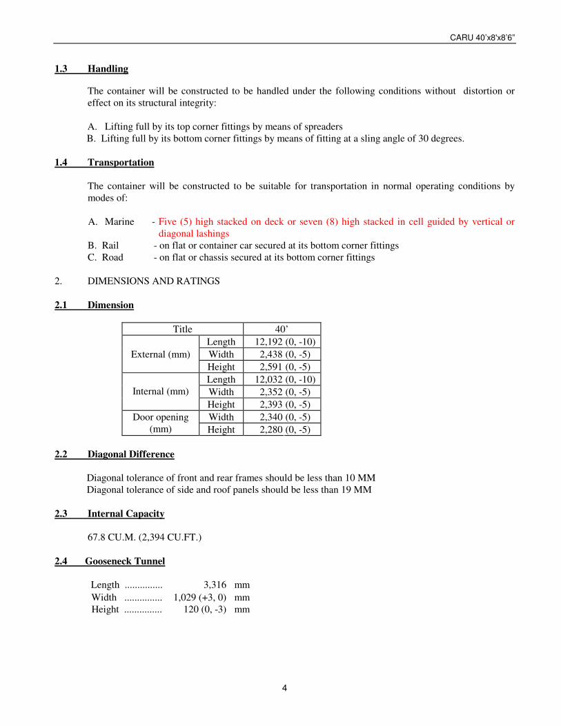
B. Rail - on flat or container car secured at its bottom corner fittings C. Road - on flat or chassis secured at its bottom corner fittings 2. DIMENSIONS AND RATINGS 2.1 Dimension
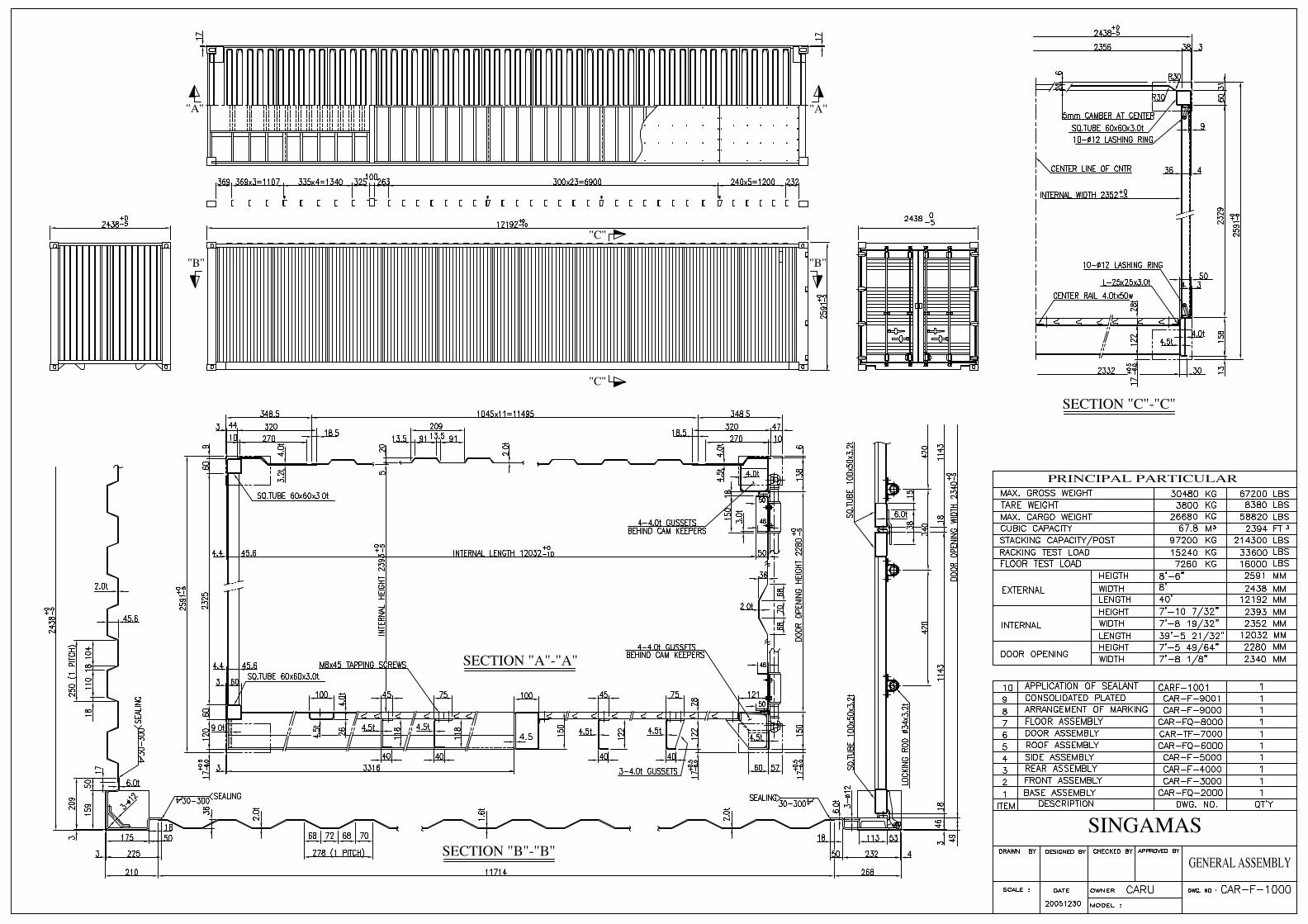
Title 40’ Length 12,192 (0, -10)
Width 2,438 (0, -5) External (mm) Height 2,591 (0, -5) Length 12,032 (0, -10) Width 2,352 (0, -5)
Internal (mm)
Height 2,393 (0, -5) Width 2,340 (0, -5) Door opening
(mm) Height 2,280 (0, -5) 2.2 Diagonal Difference
Diagonal tolerance of front and rear frames should be less than 10 MM Diagonal tolerance of side and roof panels should be less than 19 MM
2.3 Internal Capacity 67.8 CU.M. (2,394 CU.FT.) 2.4 Gooseneck Tunnel
Length ............... 3,316 mm Width ............... 1,029 (+3, 0) mm Height ............... 120 (0, -3) mm
CARU 40’x8'x8’6”
5
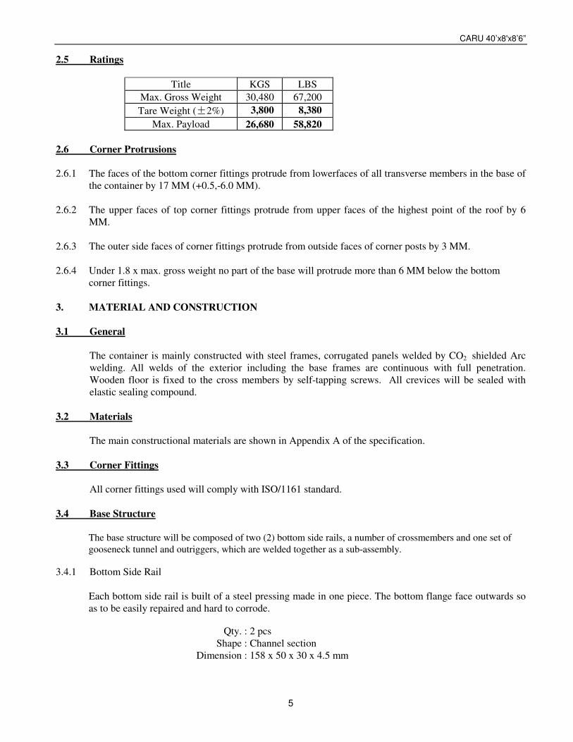
2.5 Ratings
Title KGS LBS Max. Gross Weight 30,480 67,200 Tare Weight ( 2%) 3,800 8,380
Max. Payload 26,680 58,820 2.6 Corner Protrusions 2.6.1 The faces of the bottom corner fittings protrude from lowerfaces of all transverse members in the base of
the container by 17 MM (+0.5,-6.0 MM). 2.6.2 The upper faces of top corner fittings protrude from upper faces of the highest point of the roof by 6
MM. 2.6.3 The outer side faces of corner fittings protrude from outside faces of corner posts by 3 MM. 2.6.4 Under 1.8 x max. gross weight no part of the base will protrude more than 6 MM below the bottom
corner fittings. 3. MATERIAL AND CONSTRUCTION 3.1 General The container is mainly constructed with steel frames, corrugated panels welded by CO2 shielded Arc
welding. All welds of the exterior including the base frames are continuous with full penetration. Wooden floor is fixed to the cross members by self-tapping screws. All crevices will be sealed with elastic sealing compound.
3.2 Materials The main constructional materials are shown in Appendix A of the specification. 3.3 Corner Fittings All corner fittings used will comply with ISO/1161 standard. 3.4 Base Structure
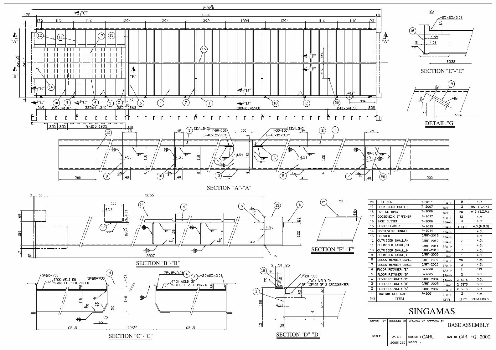
The base structure will be composed of two (2) bottom side rails, a number of crossmembers and one set of gooseneck tunnel and outriggers, which are welded together as a sub-assembly.
3.4.1 Bottom Side Rail
Each bottom side rail is built of a steel pressing made in one piece. The bottom flange face outwards so as to be easily repaired and hard to corrode.
Qty. : 2 pcs Shape : Channel section
Dimension : 158 x 50 x 30 x 4.5 mm
CARU 40’x8'x8’6”
6
3.4.2 Crossmember
The crossmembers are composed of a number of small pressed channel section and some large one located beneath each board joint of the plywood, which are placed at certain center distance. There are 3 pcs of t4.0 stiffeners in each joint member.
Shape : "C" section Small one : 122 x 45 x 40 x 4.5 mm, Qty. : 26 pcs. Large one : 122 x 75 x 40 x 4.5 mm, Qty. : 3 pcs. Stiffener : 4.0 mm thick, Qty. : 9 pcs.
3.4.3 Gooseneck Tunnel
The gooseneck tunnel consists of one piece pressed hat section tunnel plate, a number of pressed channel section tunnel bows, one box (or welded box) section rear bolster and tunnel outriggers. The gooseneck tunnel is designed according to ISO standard :
a) Tunnel plate : 4.0 mm thick, Qty. : one piece. b) Tunnel bow : 4.5 mm thick, Qty. : 12 pcs. c) Bolster : 150 x 100 x 4.5 mm, Qty. : one piece. d) Outriggers : 4.5 mm thick, Qty. : 8 pcs / each side, total : 16 pcs.
3.4.4 Floor central rail
A 4.0 x 50 mm flat bar hot-dipped galvanized 55 microns will be loosely placed on top of the crossmembers to support the floorboards at the center.
3.4.5 Floor retainer A number of 25 x 25 x 3.0 mm thick angle steel will be placed beside the bottom side rails on the
crossmembers to support the floorboards. 3.4.6 Base Gusset
Four corner gussets, t4.0 x 200 mm thick protection plates will be welded from side rail to corner fittings.
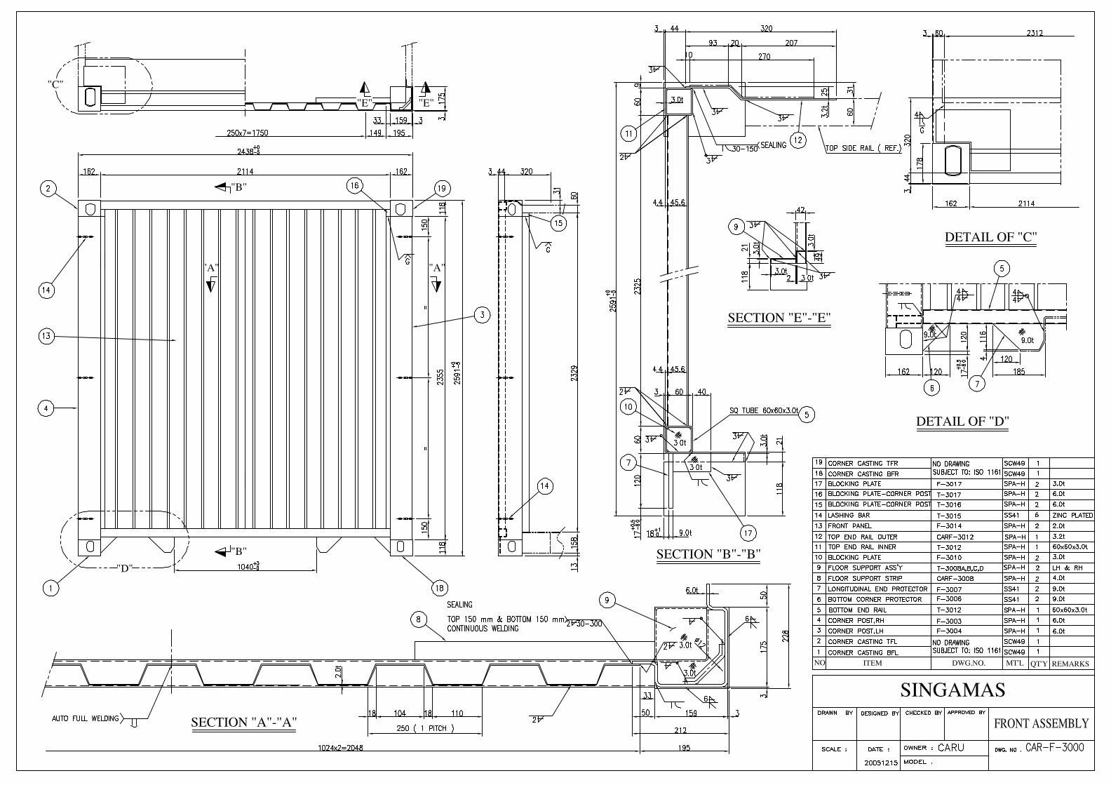
3.5 Front End The front end will be composed of front end frame and corrugated end wall, which are welded together
as a sub-assembly. 3.5.1 Front End Frame
The front end frame will be composed of two corner posts, one top end rail (sub-assembly), one bottom end rail and four corner fittings.
3.5.1.1 Front Corner Post
Each corner post is made of a 6.0 mm thick section steel pressing to ensure the suitable strength, light-weight and easy maintenance.
CARU 40’x8'x8’6”
7
3.5.1.2 Top End Rail (sub-assembly)
The front top end rail is constructed with steel square tube lower part and steel plate upper part. The upper part is extended inwards of the container certain distance with full width from front part of top corner fittings.
Lower rail : 60 x 60 x 3.0 mm
Upper part : 3.2 mm thick 3.5.1.3 Bottom end rail
The bottom end rail consists of two longitudinal end protectors and a square tube on top with flat strips as the wood supports. Two bottom corner protectors are provided adjacent to the bottom fitting to prevent damage due to any twistlock misalignment.
Longitudinal end protectors: 9.0 mm thick, Qty. : 2 pcs.
Square tube : 60 x 60 x 3.0 mm Flat strips : 4.0 mm thick, Qty. : 2 pcs.
Bottom corner protectors : 9.0 mm thick, Qty. : 2 pcs. 3.5.2 Front End Wall
The front end wall is composed of steel sheet fully vertically corrugated into trapezium section, butt joint together to form one panel by means of automatic welding.
Front end wall thickness: 2.0mm Corrugation dimension − Depth : 45.6 mm
Outerface : 110 mm Interface : 104 mm Slope : 18 mm Pitch : 250 mm
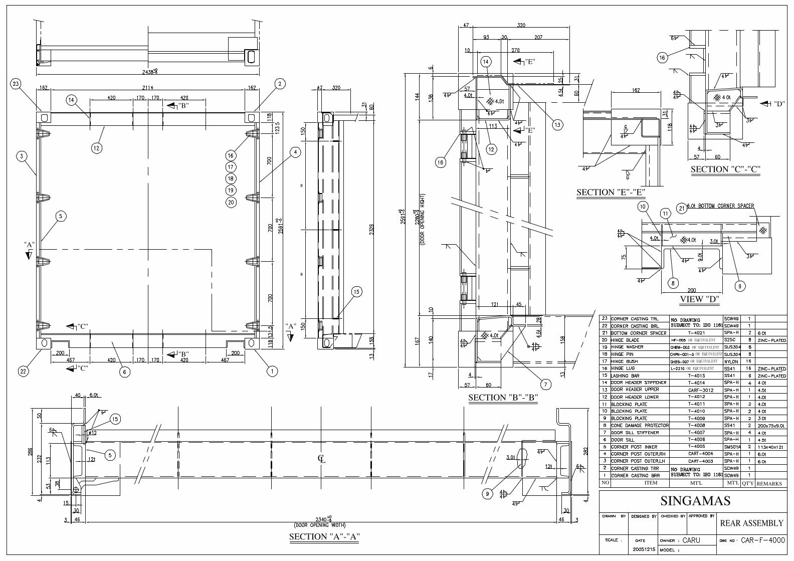
3.6 The Rear Frame
The rear frame consists of one door header, one door sill, four corner fittings and two corner posts. 3.6.1 Rear Corner Post
Each corner post is constructed from an inner part of channel shaped hot-rolled section steel and an outer part of steel pressing, welded together to form a hollow section to ensure the door opening and suitable strength against the stacking and racking force. Four (4) sets of hinge pin lugs are welded to each outer part of the corner post.
Inner part : 113 x 40 x 12 mm Outer part : 6.0 mm thick
3.6.2 Door Header
The door header is constructed from a lower part of a "U" shaped steel pressing with internal stiffener ribs at the location of the cam keeper’s backside and an upper part of steel pressing rear header plate, they are welded together to form a box section to provide a high rigidity.
Rear header : 4.0 mm thick
CARU 40’x8'x8’6”
8
Header plate : 4.5 mm thick Rib : 4.0 mm thick, Qty. : 4 pcs.
3.6.3 Door Sill
The door sill is built of a special channel section steel pressing with internal ribs as stiffeners at the backside of each cam keeper. The upper face of the sill has a slope for better drainage and the highest part is on the same level to the upper face of the wooden floor. Two channel section steel recesses (must be grind in smooth radius of 8mm) are provided adjacent to the bottom fitting to prevent damage due to any twistlock misalignment.
Door sill : 4.5 mm thick, Slope : 10 mm
Stiffener ribs : 4.0 mm thick, Qty. : 4 pcs. Channel section : 200 x 75 x 9.0 mm
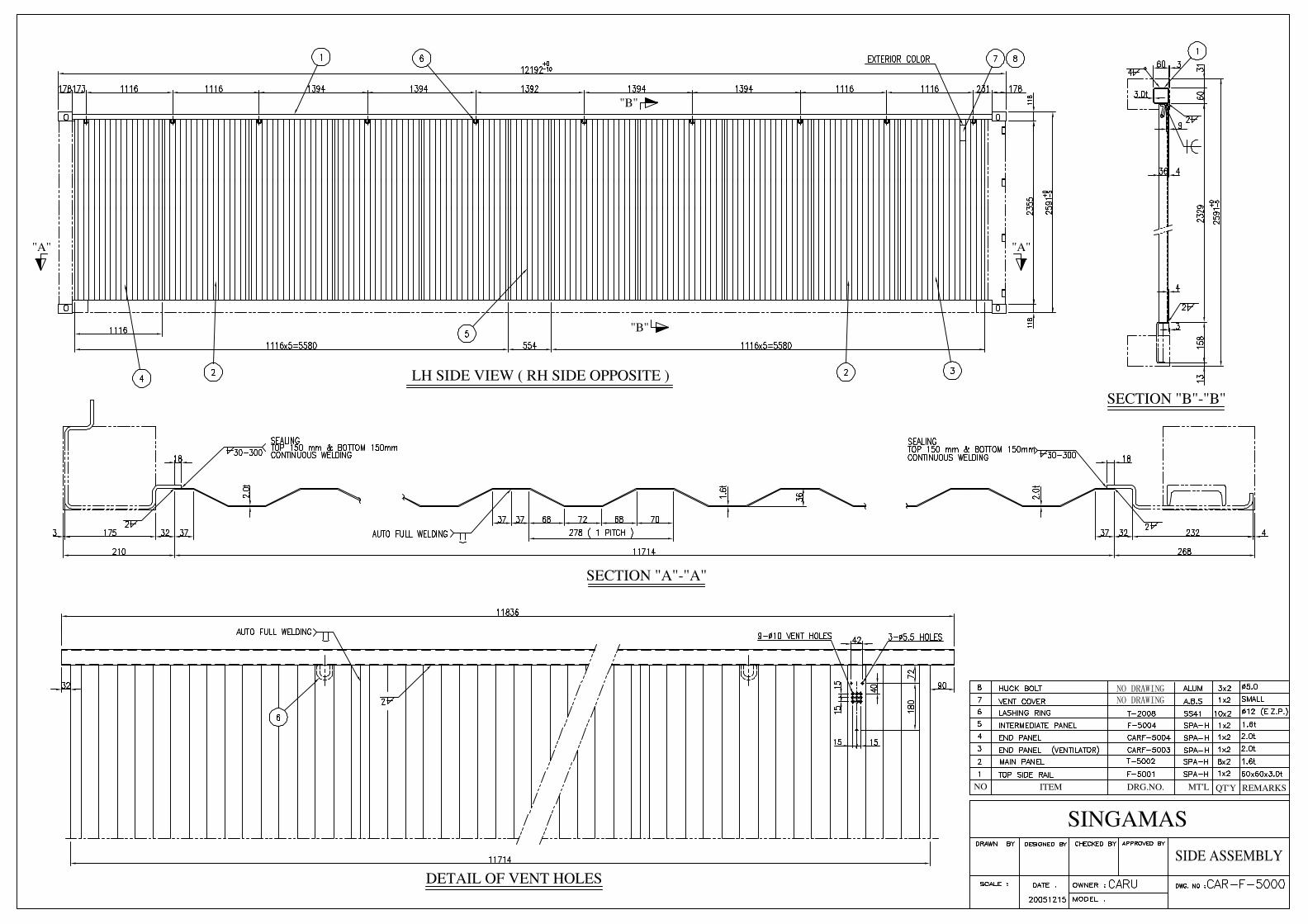
3.7 Side Wall Assembly
The side walls will be continuously welded to each other and to the side rails and corner posts. Welding penetration side panels to rails should be min.75%.
3.7.1 Top Side Rails
Each top side rail is used a square steel pipe. Rail : 60 x 60 x 3.0 mm 3.7.2 Side Walls
Each side wall will be composed of a number of sheets for the intermediate (inner) parts and outer panels at each end of side wall, fully vertically corrugated into trapezium section, butt welded together to form one panel by automatic welding.
Trapezium − Depth : 36 mm Outerface : 72 mm Interface : 70 mm Slope : 68 mm Pitch : 278 mm
Inner panel : 1.6 mm thick, Qty. : 9 pcs / each side. Outer panel : 2.0 mm thick, Qty. : 2 pcs / each side
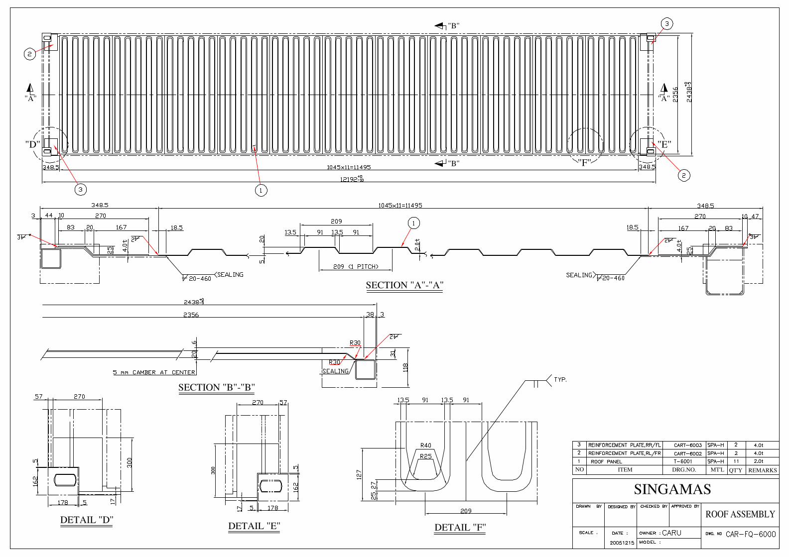
3.8 Roof
The roof will be constructed by several die-stamp corrugated steel sheets with a certain upwards camber at the center of each trough and corrugation, these sheets are butt jointed together to form one panel by automatic welding.
Corrugation shape − Depth : 20 mm
Outerface : 91 mm Interface : 91 mm Slope : 13.5 mm Pitch : 209 mm
Camber upwards : 5 mm Panel thickness : 2.0 mm Sheet Qty. : 11 pcs
CARU 40’x8'x8’6”
9
3.8.1 Roof Reinforcement Plate
Four reinforcement plates shall be mounted around the four corner fittings. dimension : 300 x 270 x 4.0 mm
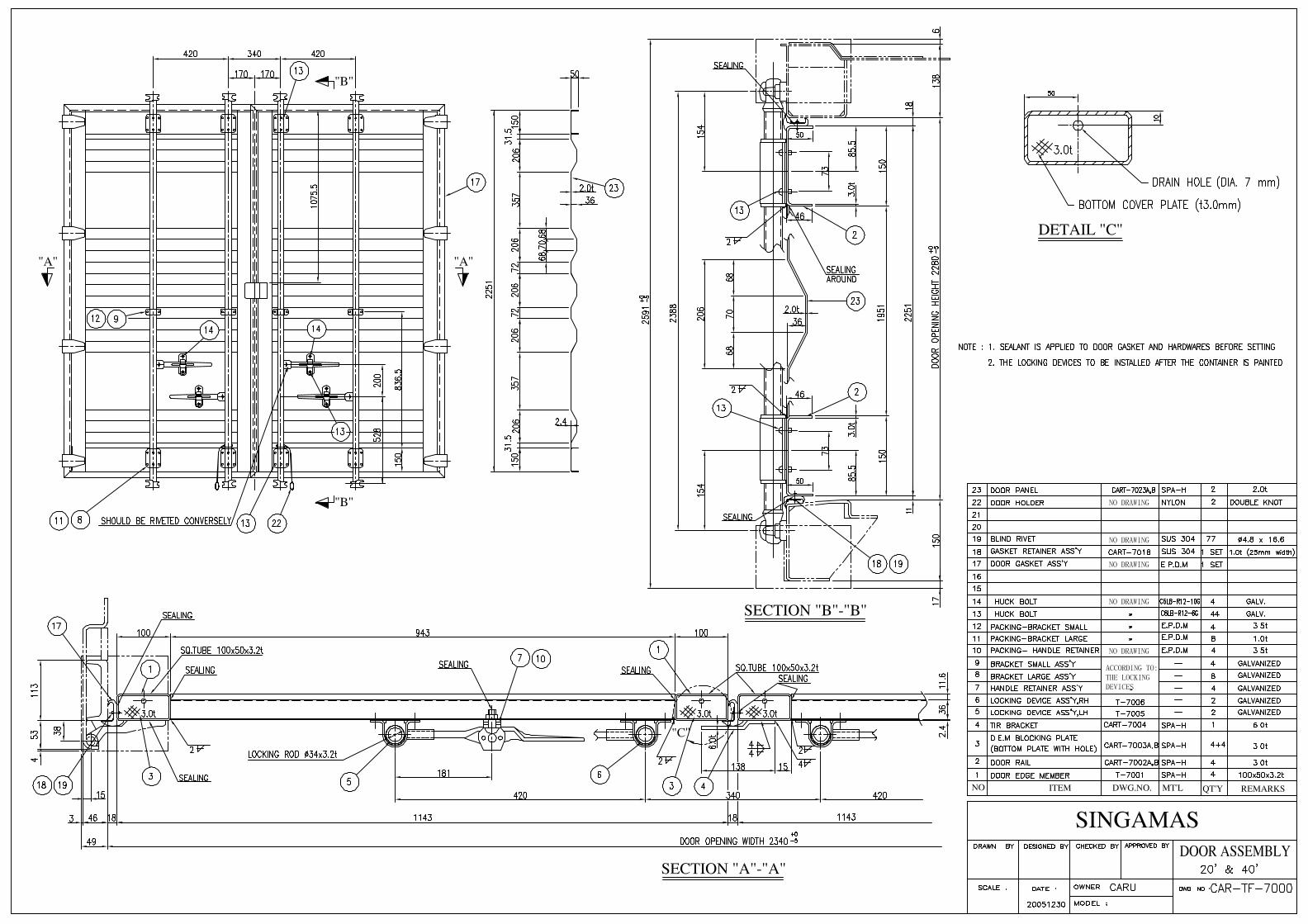
3.9 Door The door consists of two door leaves, each leaf with two locking devices, four hinges, seal gaskets and door holders.
3.9.1 Door Leaf
Each leaf consists of door panel, steel door frame which consists of vertical (inner & outer) and horizontal (upper & lower) members. They are welded together to form the rectangular door leave.
3.9.1.1 Door panel : With 5 corrugations.
Panel thickness : 2.0 mm
Depth : 36 mm Interface : 70 mm
Slope : 68 mm 3.9.1.2 Door frame : a) Vertical door member : 100 x 50 x 3.2 mm (inner & outer)
b) Horizontal door member : Channel section, 150 x 50 x 46 x 3.0 mm. 3.9.1.3 Each door is capable of swinging 270 degrees when fully opened and can be secured in that position by
means of nylon ropes attached. 3.9.1.4 The right door is so designed that the right door must be opened before the left in compliance with T.I.R.
requirements. 3.9.1.5 The bottom cover plates of all door edge members must be provided with a drain hole of 7 mm. 3.9.2 Door gasket The door gasket is of extruded EPDM with a double lip to ensure water tightness. The upper and side
gaskets are of 'J' type configuration. Bottom is of a 'C' type configuration. It is attached with sealant and secured with stainless steel retainers by stainless steel blind rivets.
3.9.3 Hinges and Pins Each door is suspended by four hinges with stainless steel pins, nylon bushings and stainless steel
washers placed at the hinge pin lugs of the rear corner posts. 3.9.4 Locking Devices Galvanized locking devices (Hot-dipped galvanized 75 microns) on a galvanized 34 MM dia. pipe are
secured to the door with huck bolts and has nylon bushings on the brackets. The Locking devices will be installed after the container is painted.
3.9.5 Door Holder and Receptacle
CARU 40’x8'x8’6”
10
A door holder per door, made of mixed nylon rope, is tied by double knot to the center-side locking rod and the receptacle (hook type) is welded to each bottom side rail to retain the door at the open position.
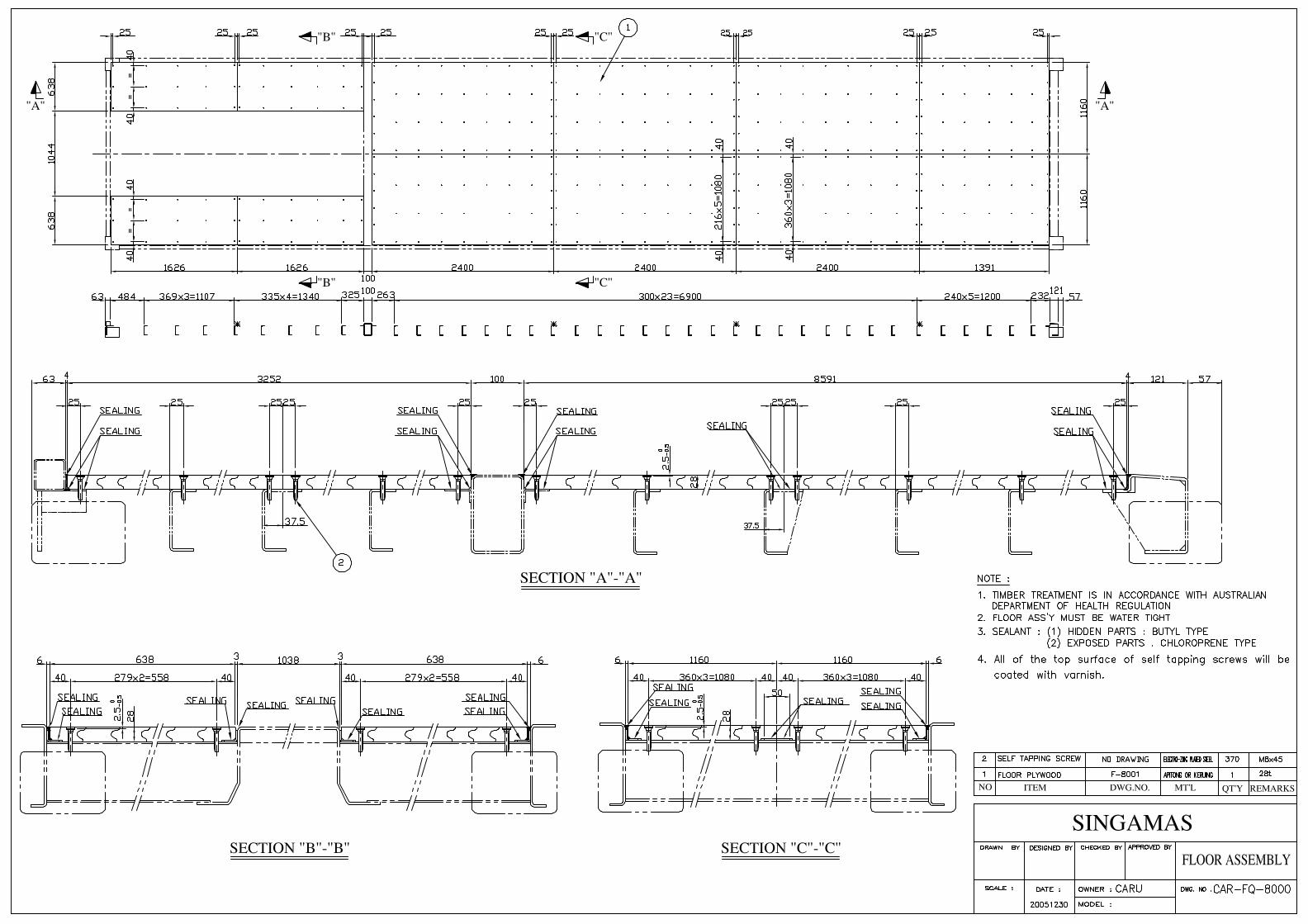
3.10 Floor 3.10.1 The Floor Boards
The floor consists of plywood. The plywood used will be certified to meet the requirements of Australian Commonwealth Dept. of Health (Plant Quarantine Treatment Schedule) for Timber Components ( T.C.T. ). The floor dimension should according to the IICL dimension standard. The plywood thickness is 28 mm.
3.10.2 Arrangement and Fixing
The plywood boards are longitudinally laid on the crossmember with a pre-blasted painted and free floating flat steel at the center and two angle steel along both side rails. The plywood boards are tightly secured to each crossmember with countersunk self-tapping electro-zinc plated steel screws and its top surface should be coated with varnish. These heads of the floor screws are countersunk below the level of the upper surface of the floor by 2.0 mm to 2.5 mm.
Screws : M8 x 45 x 16(Head) mm Screws’ Qty. : 6 pcs / end row and joint, 3 pcs / outrigger, 4 pcs / other.
3.10.2 The plywood used will be a minimum of 19 plies and will be:
A. Hardwood of a specific gravity range of 0.7-0.85 at a moisture content of 12%. E.G. Keruing, Apitong.
B. Moisture content will be 13-15% when fitted to the container.
3.11 Sealing
1. Each perimeter of the floor; 2. All the overlapped joints of inside; 3. All the holes for bolts and nuts; 4. Three sides of CSC plate and ventilators; 5. Between door gasket and door panel at 305 mm above lower gasket; 6. Details refer to the application of sealant drawing CARF-1001. Note: The application of interior sealant will be put on after water testing.
Sealant Materials : a. Chloroprene (Cargo contact area) b. Butyl (Hidden parts) c. Silicon (apply to CSC plate and ventilators)
3.12 Special Features 3.12.1 Shoring Slots: 60x40 MM slots are provided for on each of the rear corner posts so that a 2" thick batten
can be secured to give protection against shifting cargo. 3.12.2 Lashing Rings and Lashing Bars
1) Lashing rings are welded to each bottom and top side rail at corresponding recessed area of side wall.
CARU 40’x8'x8’6”
11
Lashing ring Qty. / each bottom or top side rail : 10 pcs , total : 40 pcs.
2) Lashing bars are welded on each front & rear corner post slot. Lashing bars Qty. / each front & rear corner post : 3 pcs, total : 12 pcs.
3) Capabilities of pull load of every lashing point are as following:
Lashing rings on the side rails : 1,500 kg / each Lashing bars on the corner posts: 1,500 kg / each
3.12.3 Ventilators – Two (2) ventilators should be small type fabricated from A.B.S. resin by injection molding process. They will be secured to the panel recess from right corner post of both side walls, by means of three (3) Aluminum Huck bolts.
3.12.4 Customs Seal Provision
Customs seal provision are made on each locking handle and retainer in accordance with TIR requirements.
4. SURFACE PROTECTION 4.1 Surface Preparation
All steel components, prior to forming, will be shot-blasted to a SA 2.5 standard surface by means of an automatic centrifugal shot surface cleaning machine. A weld-able primer compatible to the paint system will be applied immediately to a thickness of 10 micron to preserve the surface integrity during the assembly process. After the container is assembled it is shot-blasted again manually to clean all the welds and any other area that was contaminated during the assembly process. Slags and spatters are removed by means of grinding or needle hammers.
4.2 Paint Supplier: Chugoku Exterior: RAL 3004 Apply one coat of zinc rich primer to 30 mic. DFT. Apply one coat of epoxy primer to 40 mic. DFT. Apply one coat of Acrylic top coat to 40 mic. DFT. (50 for roof) Total 110 mic. DFT. (120 mic. DFT for roof) Interior: RAL 3009 Apply one coat of zinc rich primer to 30 mic. DFT. Apply one coat of epoxy top coat to 45 mic. DFT. Total 75 mic. DFT. Note: The gloss ratio is 25% of exterior paint. 4.3 Undercoating
The whole underside will be coated with 30 mic. of zinc rich primer and 200 mic. of Waxy or Bituminous undercoating.
Total 230 mic. DFT. 5. MARKING
CARU 40’x8'x8’6”
12
5.1 Lettering The container will be marked in accordance with ISO requirements, owner's specifications, and other
regulatory authorities. 5.2 Materials
The decals are cast vinyl of a self adhesive type and are warranted for seven (7) years against normal wear and tear. All data plates will be stainless steel and secured by stainless steel blind rivets and sealed with silicon sealant.
5.3 Plating and Stamping 5.3.1 The owner’s serial number and manufacturing number will be die-stamped with 10 mm high
characters to the top of LH and RH rear bottom corner fittings respectively. 5.3.2 Chemically etched stainless steel plates (Consolidated data plate i.e. TIR, CSC, TCT) will be
permanently riveted with stainless steel blind rivets and sealant will be applied around these plates. 6. TESTING AND INSPECTION 6.1 Materials and Parts Inspection
All materials and parts are inspected by the manufacturer's Quality Control department to ensure they are up to the specification called for in the design.
6.2 Production Line Quality Control All containers are manufactured under effective quality control procedures to meet the specified
standards. All dimensions are checked and smooth operation of the doors are ensured after each container's completion. A light and watertight test is conducted on all containers.
Quality control personnel independent of the production dept. will be inspecting on all phases of the production as well as ad hoc inspections by the classification society's surveyor and buyer's representatives to assure the quality of the container.
7. WARRANTY 7.1 Guarantee
The guarantee period will commence the day after the certification is issued by the classification society. 7.2 Paint Guarantee
The application of paint will be guaranteed against corrosion and paint failure for a period of five (5) years. The guarantee is for all faults affecting more than 10% of the painted surfaces and will assure partial or total re-painting of the containers. Normal wear/tear, or corrosion caused by acid, alkali or results of damages by abrasion, impact or accident are excluded.
Note: Corrosion is defined as rusting which exceeds RE3 (European scale of degree of rusting) on at least ten (10) percent of the total container surface coated with the concerned coating system.
CARU 40’x8'x8’6”
13
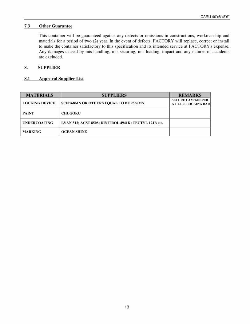
7.3 Other Guarantee This container will be guaranteed against any defects or omissions in constructions, workmanship and
materials for a period of two (2) year. In the event of defects, FACTORY will replace, correct or install to make the container satisfactory to this specification and its intended service at FACTORY's expense. Any damages caused by mis-handling, mis-securing, mis-loading, impact and any natures of accidents are excluded.
8. SUPPLIER 8.1 Approval Supplier List MATERIALS SUPPLIERS REMARKS
LOCKING DEVICE SCI8568MN OR OTHERS EQUAL TO BE 2566MN SECURE CAM/KEEPER AT T.I.R. LOCKING BAR
PAINT CHUGOKU
UNDERCOATING LVAN 512; ACST 8508; DINITROL 4941K; TECTYL 121B etc.
MARKING OCEAN SHINE
CARU 40’x8'x8’6”
14
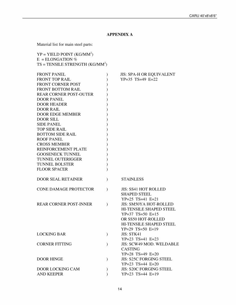
APPENDIX A Material list for main steel parts: YP = YIELD POINT (KG/MM2) E = ELONGATION % TS = TENSILE STRENGTH (KG/MM2) FRONT PANEL ) JIS: SPA-H OR EQUIVALENT FRONT TOP RAIL ) YP=35 TS=49 E=22 FRONT CORNER POST ) FRONT BOTTOM RAIL ) REAR CORNER POST-OUTER ) DOOR PANEL ) DOOR HEADER ) DOOR RAIL ) DOOR EDGE MEMBER ) DOOR SILL ) SIDE PANEL ) TOP SIDE RAIL ) BOTTOM SIDE RAIL ) ROOF PANEL ) CROSS MEMBER ) REINFORCEMENT PLATE ) GOOSENECK TUNNEL ) TUNNEL OUTERIGGER ) TUNNEL BOLSTER ) FLOOR SPACER ) DOOR SEAL RETAINER ) STAINLESS CONE DAMAGE PROTECTOR ) JIS: SS41 HOT ROLLED SHAPED STEEL YP=25 TS=41 E=21 REAR CORNER POST-INNER ) JIS: SM50YA HOT-ROLLED HI-TENSILE SHAPED STEEL YP=37 TS=50 E=15 OR SS50 HOT-ROLLED HI-TENSILE SHAPED STEEL YP=29 TS=50 E=19 LOCKING BAR ) JIS: STK41 YP=23 TS=41 E=23 CORNER FITTING ) JIS: SCW49 MOD. WELDABLE CASTING YP=28 TS=49 E=20 DOOR HINGE ) JIS: S25C FORGING STEEL YP=23 TS=44 E=20 DOOR LOCKING CAM ) JIS: S20C FORGING STEEL AND KEEPER ) YP=23 TS=44 E=19
CARU 40’x8'x8’6”
15
APPENDIX B
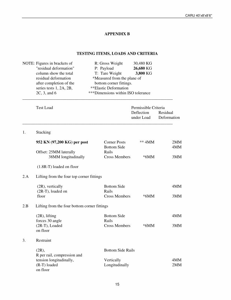
TESTING ITEMS, LOADS AND CRITERIA NOTE: Figures in brackets of R: Gross Weight 30,480 KG "residual deformation" P: Payload 26,680 KG column show the total T: Tare Weight 3,800 KG residual deformation *Measured from the plane of after completion of the bottom corner fittings. series tests 1, 2A, 2B, **Elastic Deformation 2C, 3, and 6 ***Dimensions within ISO tolerance ________________________________________________________________________ Test Load Permissible Criteria Deflection Residual under Load Deformation ________________________________________________________________________ 1. Stacking 952 KN (97,200 KG) per post Corner Posts ** 4MM 2MM Bottom Side 4MM Offset: 25MM laterally Rails 38MM longitudinally Cross Members *6MM 3MM (1.8R-T) loaded on floor 2.A Lifting from the four top corner fittings (2R), vertically Bottom Side 4MM (2R-T), loaded on Rails floor Cross Members *6MM 3MM 2.B Lifting from the four bottom corner fittings (2R), lifting Bottom Side 4MM forces 30 angle Rails (2R-T), Loaded Cross Members *6MM 3MM on floor 3. Restraint (2R), Bottom Side Rails R per rail, compression and tension longitudinally, Vertically 4MM (R-T) loaded Longitudinally 2MM on floor
CARU 40’x8'x8’6”
16
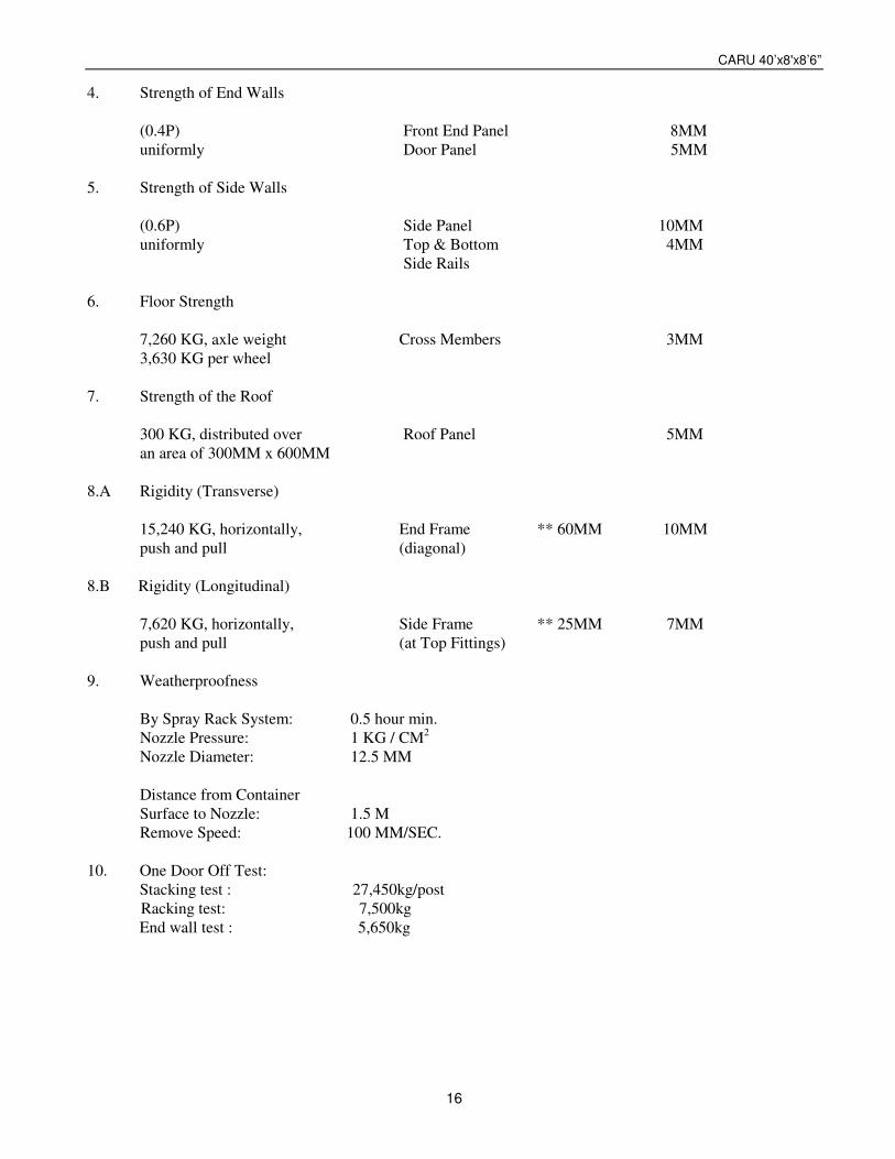
4. Strength of End Walls (0.4P) Front End Panel 8MM uniformly Door Panel 5MM 5. Strength of Side Walls (0.6P) Side Panel 10MM uniformly Top & Bottom 4MM Side Rails 6. Floor Strength 7,260 KG, axle weight Cross Members 3MM 3,630 KG per wheel 7. Strength of the Roof 300 KG, distributed over Roof Panel 5MM an area of 300MM x 600MM 8.A Rigidity (Transverse) 15,240 KG, horizontally, End Frame ** 60MM 10MM push and pull (diagonal) 8.B Rigidity (Longitudinal) 7,620 KG, horizontally, Side Frame ** 25MM 7MM push and pull (at Top Fittings) 9. Weatherproofness By Spray Rack System: 0.5 hour min. Nozzle Pressure: 1 KG / CM2
Nozzle Diameter: 12.5 MM Distance from Container Surface to Nozzle: 1.5 M Remove Speed: 100 MM/SEC. 10. One Door Off Test: Stacking test : 27,450kg/post
Racking test: 7,500kg End wall test : 5,650kg