Embed Size (px)
Citation preview
Sewer Systems
Precast Concrete Solutions

Manholes . . . . . . . . . . . . . . . . . . . . . . . . . . . . . . . . . . . . . . . . . . . . . . . . . . . . . . . . . . . . . . . . . . . . . . . . . . . . . . . . . . . . . . . . . . . . . 4
Type of connections . . . . . . . . . . . . . . . . . . . . . . . . . . . . . . . . . . . . . . . . . . . . . . . . . . . . . . . . . . . . . . . . . . . . . . . . . . . . . . . . . . . . 6
Manhole schedule . . . . . . . . . . . . . . . . . . . . . . . . . . . . . . . . . . . . . . . . . . . . . . . . . . . . . . . . . . . . . . . . . . . . . . . . . . . . . . . . . . . . . . 8
MS manhole 600x600 internal . . . . . . . . . . . . . . . . . . . . . . . . . . . . . . . . . . . . . . . . . . . . . . . . . . . . . . . . . . . . . . . . . . . . . . . . . . . . 9
MS manhole 800x800 internal . . . . . . . . . . . . . . . . . . . . . . . . . . . . . . . . . . . . . . . . . . . . . . . . . . . . . . . . . . . . . . . . . . . . . . . . . . . 10
MS manhole 1000x1000 internal . . . . . . . . . . . . . . . . . . . . . . . . . . . . . . . . . . . . . . . . . . . . . . . . . . . . . . . . . . . . . . . . . . . . . . . . . 11
MS manhole 1250x1250 internal . . . . . . . . . . . . . . . . . . . . . . . . . . . . . . . . . . . . . . . . . . . . . . . . . . . . . . . . . . . . . . . . . . . . . . . . . 12
MS manhole 1500x1500 internal . . . . . . . . . . . . . . . . . . . . . . . . . . . . . . . . . . . . . . . . . . . . . . . . . . . . . . . . . . . . . . . . . . . . . . . . . 13
MS manhole 2000x2000 internal . . . . . . . . . . . . . . . . . . . . . . . . . . . . . . . . . . . . . . . . . . . . . . . . . . . . . . . . . . . . . . . . . . . . . . . . . 14
Lifting manholes . . . . . . . . . . . . . . . . . . . . . . . . . . . . . . . . . . . . . . . . . . . . . . . . . . . . . . . . . . . . . . . . . . . . . . . . . . . . . . . . . . . . . . 15
Special shaped manholes/trapezium
for pipe sizes Ø900, Ø1050, Ø1200, Ø1350, Ø1500 . . . . . . . . . . . . . . . . . . . . . . . . . . . . . . . . . . . . . . . . . . . . . . . . . . . . . . . . . . . 16
Seating rings . . . . . . . . . . . . . . . . . . . . . . . . . . . . . . . . . . . . . . . . . . . . . . . . . . . . . . . . . . . . . . . . . . . . . . . . . . . . . . . . . . . . . . . . . 17
Vario manholes . . . . . . . . . . . . . . . . . . . . . . . . . . . . . . . . . . . . . . . . . . . . . . . . . . . . . . . . . . . . . . . . . . . . . . . . . . . . . . . . . . . . . . . 18
Specialties. . . . . . . . . . . . . . . . . . . . . . . . . . . . . . . . . . . . . . . . . . . . . . . . . . . . . . . . . . . . . . . . . . . . . . . . . . . . . . . . . . . . . . . . . . . . 20
Attenuation sewers and manholes . . . . . . . . . . . . . . . . . . . . . . . . . . . . . . . . . . . . . . . . . . . . . . . . . . . . . . . . . . . . . . . . . . . . . . . 22
Reservoirs/storage tanks. . . . . . . . . . . . . . . . . . . . . . . . . . . . . . . . . . . . . . . . . . . . . . . . . . . . . . . . . . . . . . . . . . . . . . . . . . . . . . . . 23
Adjustable weirs . . . . . . . . . . . . . . . . . . . . . . . . . . . . . . . . . . . . . . . . . . . . . . . . . . . . . . . . . . . . . . . . . . . . . . . . . . . . . . . . . . . . . . 26
Headwalls. . . . . . . . . . . . . . . . . . . . . . . . . . . . . . . . . . . . . . . . . . . . . . . . . . . . . . . . . . . . . . . . . . . . . . . . . . . . . . . . . . . . . . . . . . . . 27
Kijlstra Precast and the Environment. . . . . . . . . . . . . . . . . . . . . . . . . . . . . . . . . . . . . . . . . . . . . . . . . . . . . . . . . . . . . . . . . . . . . . 30
Content
All Kijlstra documents relating to concrete are compiled with the greatest degree of care. No rights may be derived from this edi-tion and/or from any errata contained there in. We reserve the right to make changes to the range, dimensions, colour, struc-ture of our products. Details of products that do not appear in this edition are available upon request. Products marked “from stock” may at certain times be subject to a delivery delay.
Measurements are in mm unless otherwise stated.
3
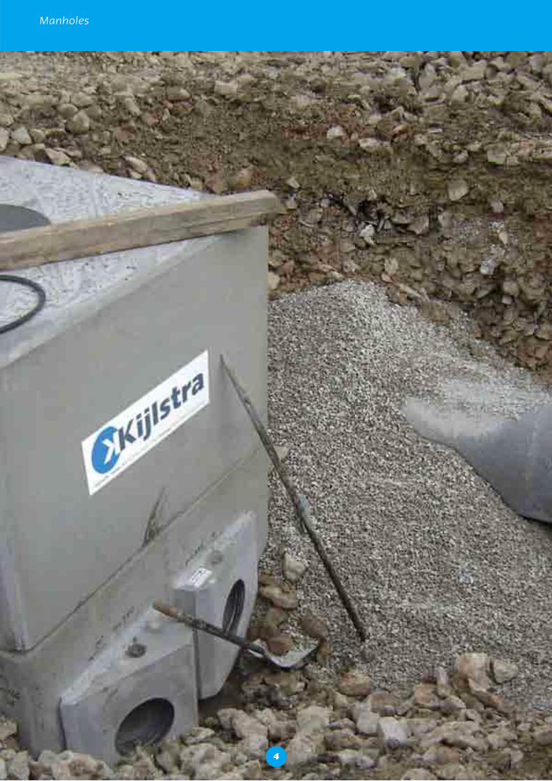
Manholes
4
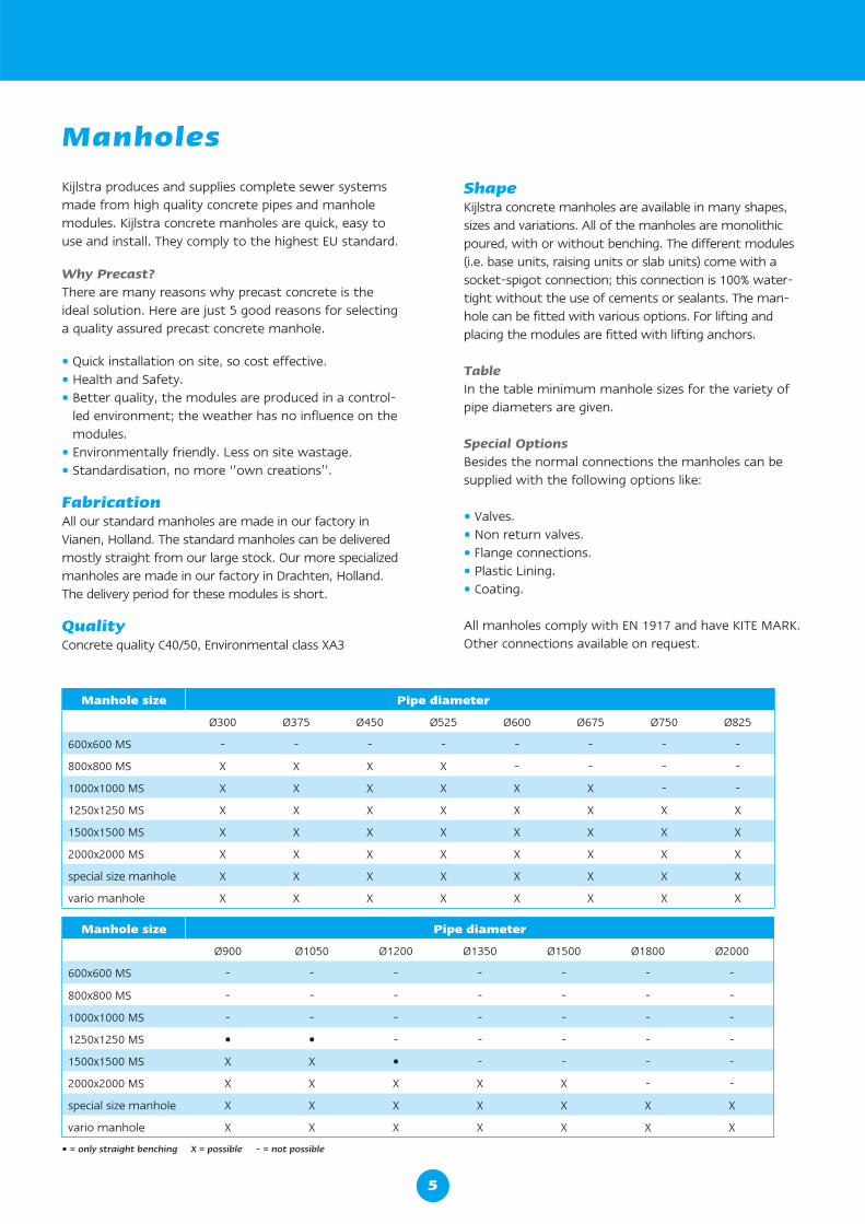
Manhole size Pipe diameter
Ø300 Ø375 Ø450 Ø525 Ø600 Ø675 Ø750 Ø825
600x600 MS - - - - - - - -
800x800 MS X X X X - - - -
1000x1000 MS X X X X X X - -
1250x1250 MS X X X X X X X X
1500x1500 MS X X X X X X X X
2000x2000 MS X X X X X X X X
special size manhole X X X X X X X X
vario manhole X X X X X X X X
Manhole size Pipe diameter
Ø900 Ø1050 Ø1200 Ø1350 Ø1500 Ø1800 Ø2000
600x600 MS - - - - - - -
800x800 MS - - - - - - -
1000x1000 MS - - - - - - -
1250x1250 MS • • - - - - -
1500x1500 MS X X • - - - -
2000x2000 MS X X X X X - -
special size manhole X X X X X X X
vario manhole X X X X X X X
• = only straight benching X = possible - = not possible
Kijlstra produces and supplies complete sewer systems made from high quality concrete pipes and manhole modules. Kijlstra concrete manholes are quick, easy to use and install. They comply to the highest EU standard.
Why Precast?There are many reasons why precast concrete is the ideal solution. Here are just 5 good reasons for selecting a quality assured precast concrete manhole.
• Quick installation on site, so cost effective.• Health and Safety.• Better quality, the modules are produced in a control-
led environment; the weather has no influence on the modules.
• Environmentally friendly. Less on site wastage.• Standardisation, no more ‘’own creations’’.
FabricationAll our standard manholes are made in our factory in Vianen, Holland. The standard manholes can be delivered mostly straight from our large stock. Our more specialized manholes are made in our factory in Drachten, Holland. The delivery period for these modules is short.
QualityConcrete quality C40/50, Environmental class XA3
ShapeKijlstra concrete manholes are available in many shapes, sizes and variations. All of the manholes are monolithic poured, with or without benching. The different modules (i.e. base units, raising units or slab units) come with a socket-spigot connection; this connection is 100% water-tight without the use of cements or sealants. The man-hole can be fitted with various options. For lifting and placing the modules are fitted with lifting anchors.
TableIn the table minimum manhole sizes for the variety of pipe diameters are given.
Special OptionsBesides the normal connections the manholes can be supplied with the following options like:
• Valves.• Non return valves.• Flange connections.• Plastic Lining.• Coating.
All manholes comply with EN 1917 and have KITE MARK.Other connections available on request.
Manholes
5
Manholes
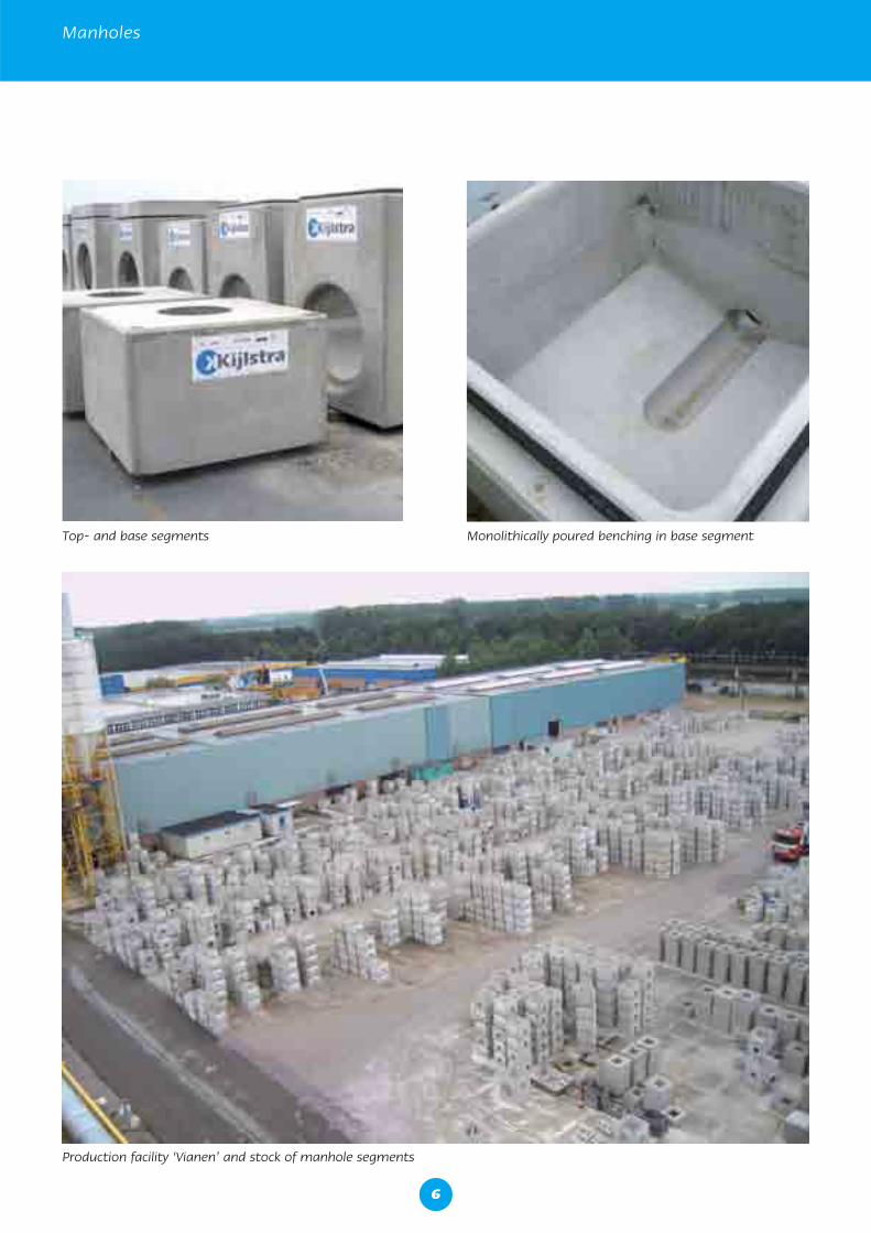
Top- and base segments Monolithically poured benching in base segment
Production facility ‘Vianen’ and stock of manhole segments
6
Type of connections for concrete pipes
spig
ot
cut
pipe
cut
pipe
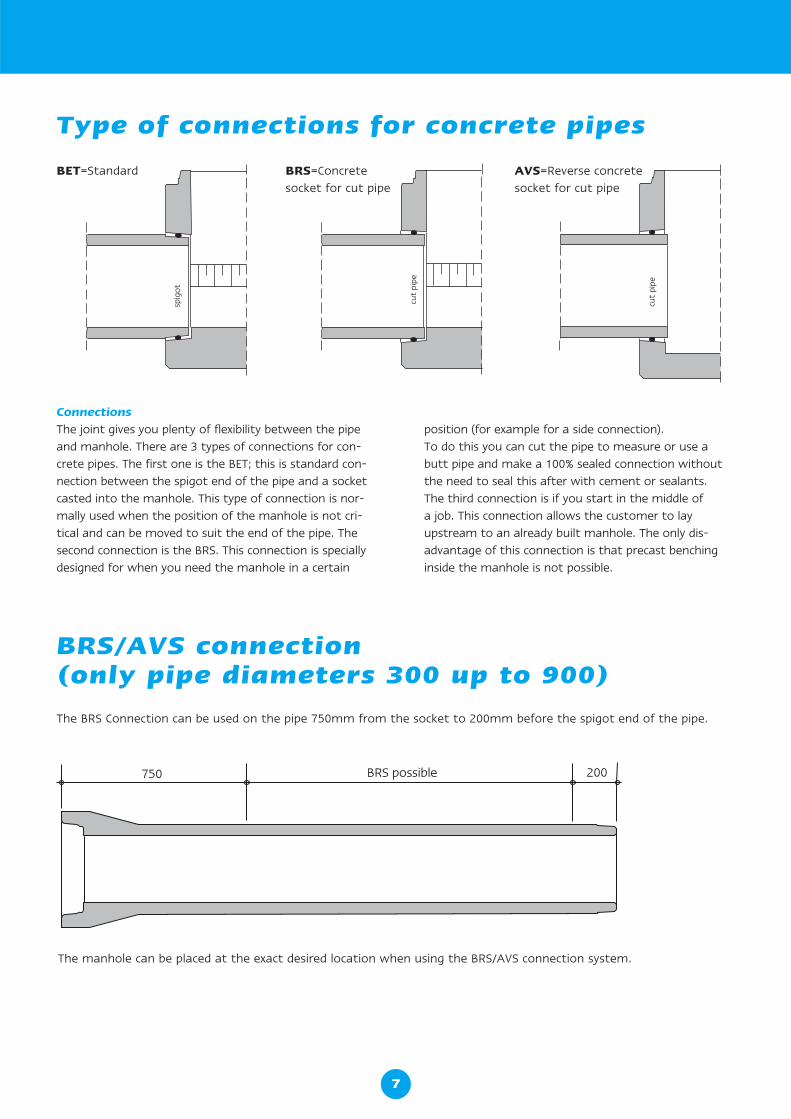
BET=Standard BRS=Concrete socket for cut pipe
AVS=Reverse concrete socket for cut pipe
BRS/AVS connection (only pipe diameters 300 up to 900)
The BRS Connection can be used on the pipe 750mm from the socket to 200mm before the spigot end of the pipe.
The manhole can be placed at the exact desired location when using the BRS/AVS connection system.
ConnectionsThe joint gives you plenty of flexibility between the pipe and manhole. There are 3 types of connections for con-crete pipes. The first one is the BET; this is standard con-nection between the spigot end of the pipe and a socket casted into the manhole. This type of connection is nor-mally used when the position of the manhole is not cri-tical and can be moved to suit the end of the pipe. The second connection is the BRS. This connection is specially designed for when you need the manhole in a certain
position (for example for a side connection). To do this you can cut the pipe to measure or use a butt pipe and make a 100% sealed connection without the need to seal this after with cement or sealants. The third connection is if you start in the middle of a job. This connection allows the customer to lay upstream to an already built manhole. The only dis-advantage of this connection is that precast benching inside the manhole is not possible.
7
Manholes
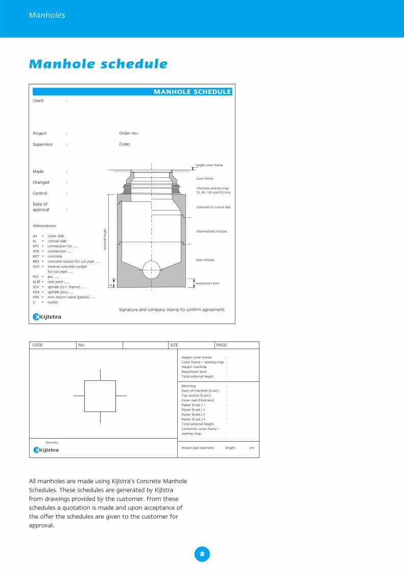
All manholes are made using Kijlstra’s Concrete Manhole Schedules. These schedules are generated by Kijlstra from drawings provided by the customer. From these schedules a quotation is made and upon acceptance of the offer the schedules are given to the customer for approval.
height cover frame
cover frame
thickness seating rings 50, 80, 100 and150 mm
coverslab or conical slab
intermediate module
base module
base/invert levelH
exte
rnal
hei
ght
Signature and company stamp to confirm agreement:
Client :
Project :
Supervisor :
Made :
Changed :
Control :
Date ofapproval :
Abbreviations:
ad = cover slabks = conical slabSPV = connection for .....SPR = connection .....BET = concreteBRS = concrete socket for cut pipe .....AVS = reverse concrete socket for cut pipe .....PVC = pvc .....KLM = click joint .....SCH = spindle (G.Y. frame) .....KRA = spindle (pvc) .....KRK = non-return valve (plastic) .....U = outlet
MANHOLE SCHEDULE
Order no.:
Code:
CODE No. SIZE PAGE
Height cover frame :Cover frame + seating rings :Height manhole :Base/invert level :Total external height :
Benching :Base of manhole (h.ext.) :Top section (h.ext.) :Cover slab (thickness) :Raiser (h.ext.) 1 :Raiser (h.ext.) 2 :Raiser (h.ext.) 3 :Raiser (h.ext.) 4 :Total external height :Correction cover frame + seating rings :
Rocker pipe diameter length cm
Remarks:
Manhole schedule
8
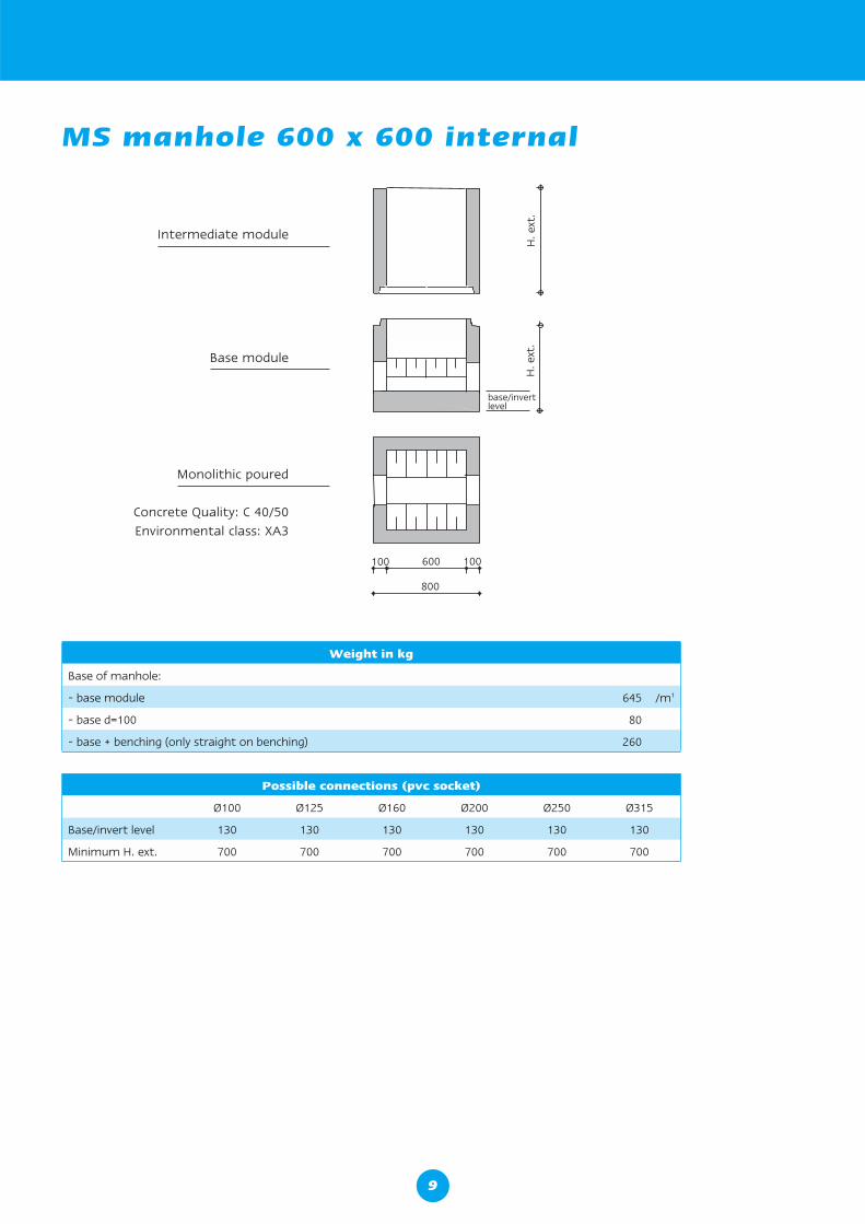
MS manhole 600 x 600 internal
600 100100
800
H. e
xt.
base/invertlevel
H. e
xt.
Intermediate module
Base module
Monolithic poured
Concrete Quality: C 40/50Environmental class: XA3
Weight in kg
Base of manhole:
- base module 645 /m1
- base d=100 80
- base + benching (only straight on benching) 260
Possible connections (pvc socket)
Ø100 Ø125 Ø160 Ø200 Ø250 Ø315
Base/invert level 130 130 130 130 130 130
Minimum H. ext. 700 700 700 700 700 700
9
Manholes
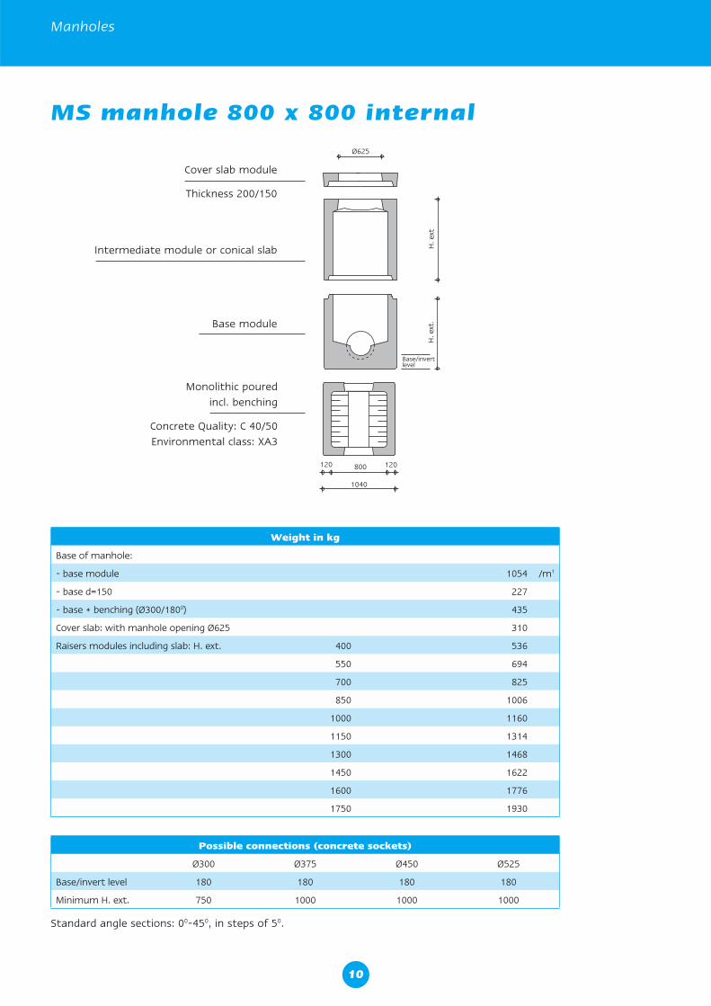
MS manhole 800 x 800 internal
Weight in kg
Base of manhole:
- base module 1054 /m1
- base d=150 227
- base + benching (Ø300/1800) 435
Cover slab: with manhole opening Ø625 310
Raisers modules including slab: H. ext. 400 536
550 694
700 825
850 1006
1000 1160
1150 1314
1300 1468
1450 1622
1600 1776
1750 1930
Possible connections (concrete sockets)
Ø300 Ø375 Ø450 Ø525
Base/invert level 180 180 180 180
Minimum H. ext. 750 1000 1000 1000
Cover slab module
Thickness 200/150
Base module
Intermediate module or conical slab
Monolithic pouredincl. benching
Concrete Quality: C 40/50Environmental class: XA3
Standard angle sections: 00-450, in steps of 50.
10
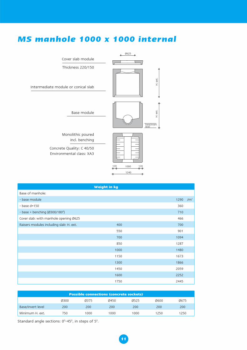
Weight in kg
Base of manhole:
- base module 1290 /m1
- base d=150 360
- base + benching (Ø300/1800) 710
Cover slab: with manhole opening Ø625 466
Raisers modules including slab: H. ext. 400 700
550 901
700 1094
850 1287
1000 1480
1150 1673
1300 1866
1450 2059
1600 2252
1750 2445
Cover slab module
Thickness 220/150
Base module
Intermediate module or conical slab
Possible connections (concrete sockets)
Ø300 Ø375 Ø450 Ø525 Ø600 Ø675
Base/invert level 200 200 200 200 200 200
Minimum H. ext. 750 1000 1000 1000 1250 1250
MS manhole 1000 x 1000 internal
Monolithic pouredincl. benching
Concrete Quality: C 40/50Environmental class: XA3
Standard angle sections: 00-450, in steps of 50.
11
Manholes
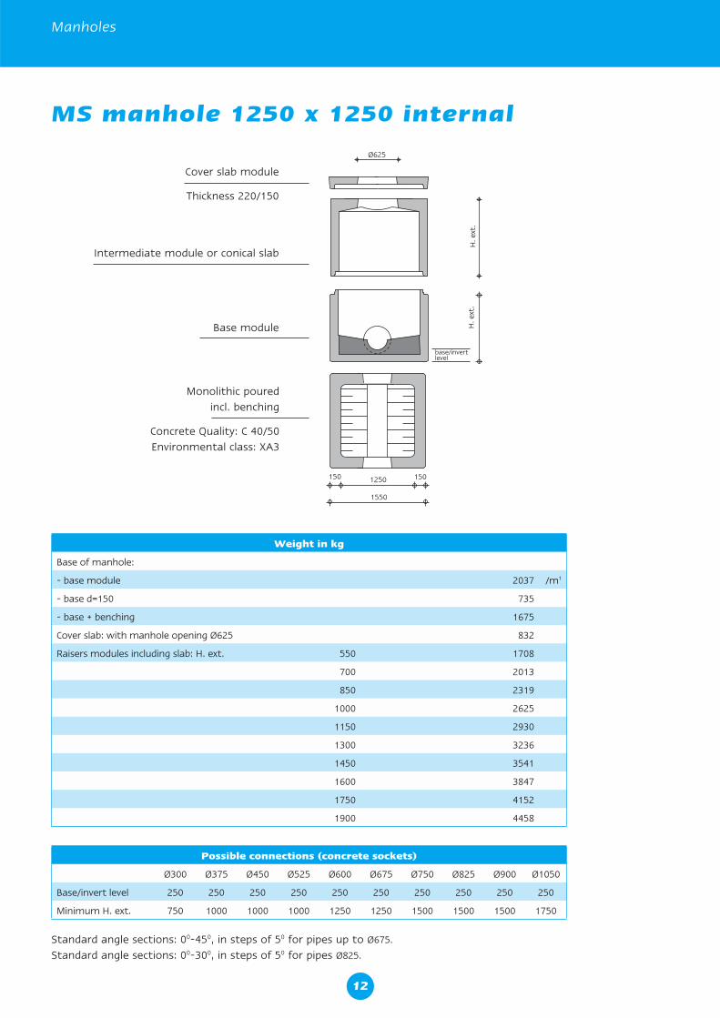
MS manhole 1250 x 1250 internal
Weight in kg
Base of manhole:
- base module 2037 /m1
- base d=150 735
- base + benching 1675
Cover slab: with manhole opening Ø625 832
Raisers modules including slab: H. ext. 550 1708
700 2013
850 2319
1000 2625
1150 2930
1300 3236
1450 3541
1600 3847
1750 4152
1900 4458
Possible connections (concrete sockets)
Ø300 Ø375 Ø450 Ø525 Ø600 Ø675 Ø750 Ø825 Ø900 Ø1050
Base/invert level 250 250 250 250 250 250 250 250 250 250
Minimum H. ext. 750 1000 1000 1000 1250 1250 1500 1500 1500 1750
Cover slab module
Thickness 220/150
Base module
Intermediate module or conical slab
Monolithic pouredincl. benching
Concrete Quality: C 40/50Environmental class: XA3
Standard angle sections: 00-450, in steps of 50 for pipes up to Ø675.
Standard angle sections: 00-300, in steps of 50 for pipes Ø825.
12
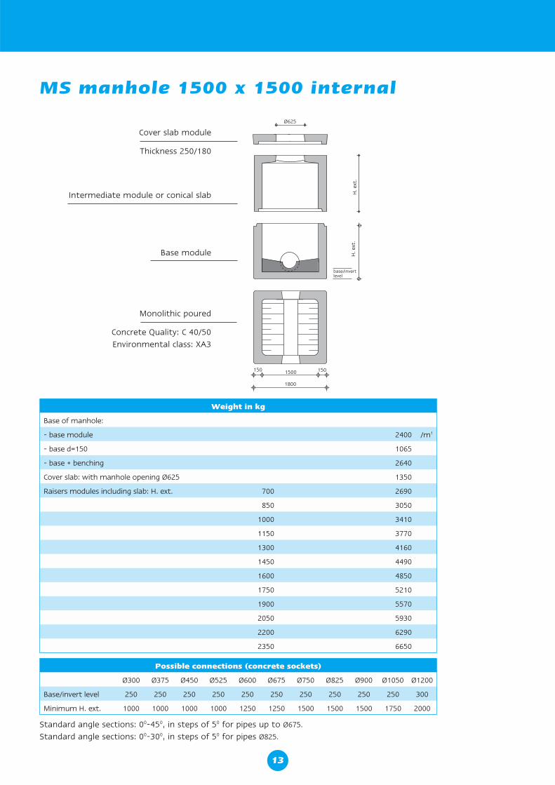
Standard angle sections: 00-450, in steps of 50 for pipes up to Ø675.
Standard angle sections: 00-300, in steps of 50 for pipes Ø825.
Weight in kg
Base of manhole:
- base module 2400 /m1
- base d=150 1065
- base + benching 2640
Cover slab: with manhole opening Ø625 1350
Raisers modules including slab: H. ext. 700 2690
850 3050
1000 3410
1150 3770
1300 4160
1450 4490
1600 4850
1750 5210
1900 5570
2050 5930
2200 6290
2350 6650
Cover slab module
Thickness 250/180
Base module
Intermediate module or conical slab
MS manhole 1500 x 1500 internal
Monolithic poured
Concrete Quality: C 40/50Environmental class: XA3
Possible connections (concrete sockets)
Ø300 Ø375 Ø450 Ø525 Ø600 Ø675 Ø750 Ø825 Ø900 Ø1050 Ø1200
Base/invert level 250 250 250 250 250 250 250 250 250 250 300
Minimum H. ext. 1000 1000 1000 1000 1250 1250 1500 1500 1500 1750 2000
13
Manholes
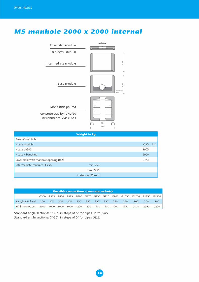
MS manhole 2000 x 2000 internal
Cover slab module
Thickness 280/200
Base module
Intermediate module
Monolithic poured
Concrete Quality: C 40/50Environmental class: XA3
Weight in kg
Base of manhole:
- base module 4245 /m1
- base d=200 1905
- base + benching 5900
Cover slab: with manhole opening Ø625 2743
Intermediate modules H. ext. min. 750
max. 2450
in steps of 50 mm
Possible connections (concrete sockets)
Ø300 Ø375 Ø450 Ø525 Ø600 Ø675 Ø750 Ø825 Ø900 Ø1050 Ø1200 Ø1350 Ø1500
Base/invert level 250 250 250 250 250 250 250 250 250 250 300 300 300
Minimum H. ext. 1000 1000 1000 1000 1250 1250 1500 1500 1500 1750 2000 2250 2250
Standard angle sections: 00-450, in steps of 50 for pipes up to Ø675.
Standard angle sections: 00-300, in steps of 50 for pipes Ø825.
14
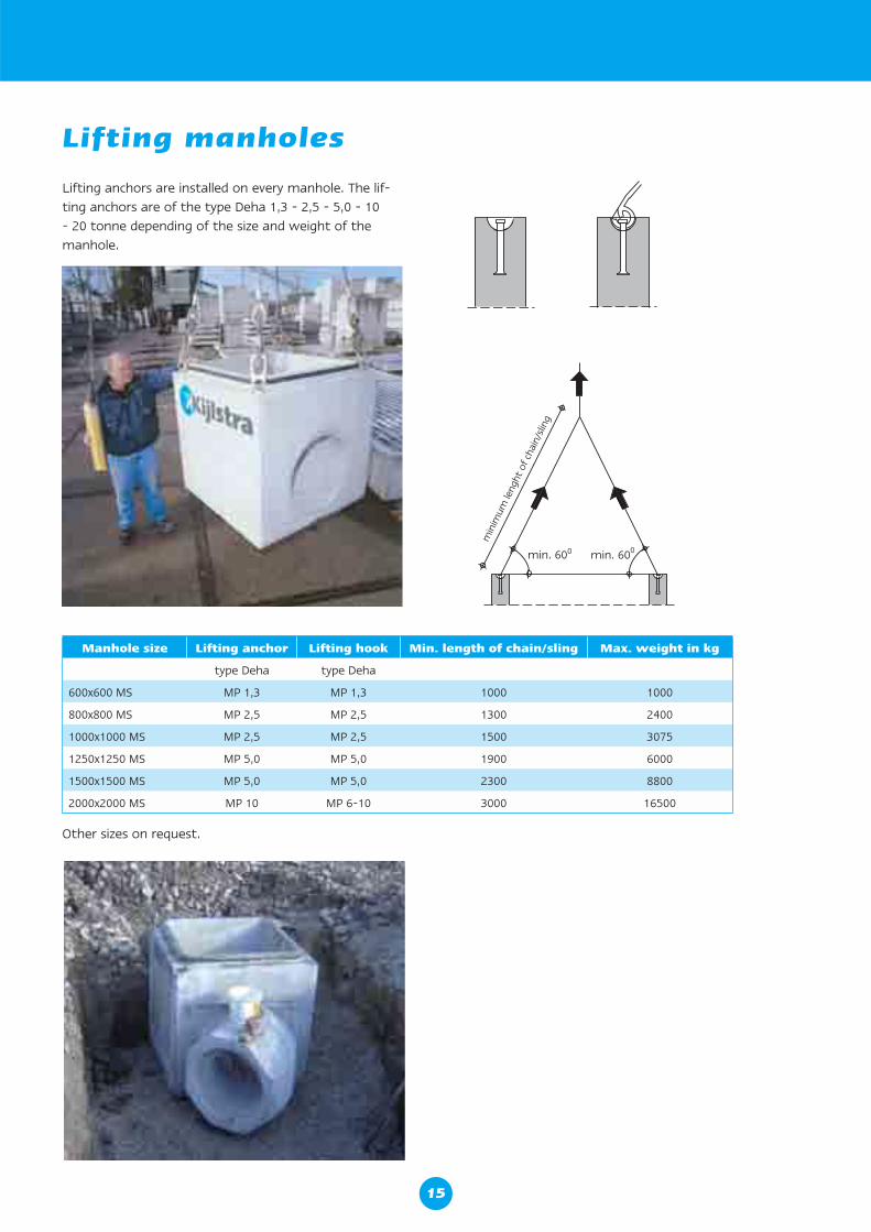
Lifting anchors are installed on every manhole. The lif-ting anchors are of the type Deha 1,3 - 2,5 - 5,0 - 10 - 20 tonne depending of the size and weight of the manhole.
Lifting manholes
Manhole size Lifting anchor Lifting hook Min. length of chain/sling Max. weight in kg
type Deha type Deha
600x600 MS MP 1,3 MP 1,3 1000 1000
800x800 MS MP 2,5 MP 2,5 1300 2400
1000x1000 MS MP 2,5 MP 2,5 1500 3075
1250x1250 MS MP 5,0 MP 5,0 1900 6000
1500x1500 MS MP 5,0 MP 5,0 2300 8800
2000x2000 MS MP 10 MP 6-10 3000 16500
Other sizes on request.
15
Manholes
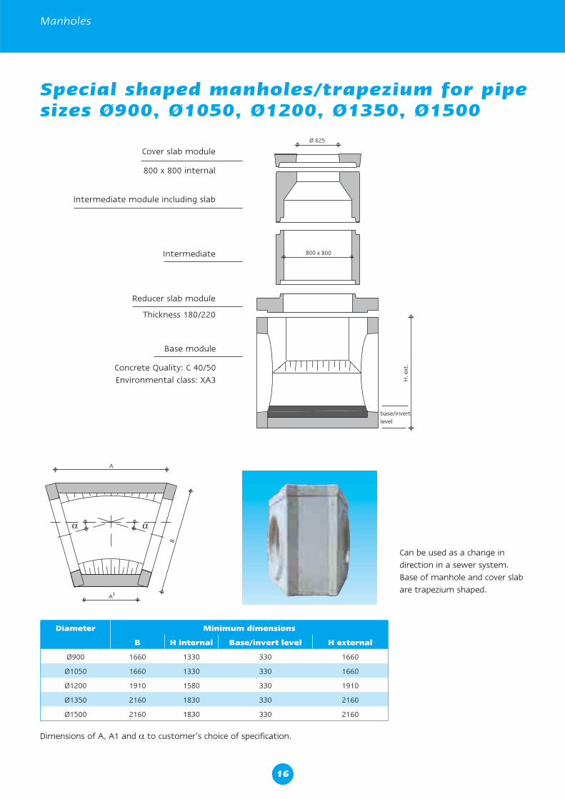
Special shaped manholes/trapezium for pipe sizes Ø900, Ø1050, Ø1200, Ø1350, Ø1500
Cover slab module
800 x 800 internal
Reducer slab module
Thickness 180/220
Intermediate
Intermediate module including slab
Base module
Concrete Quality: C 40/50Environmental class: XA3
Can be used as a change in direction in a sewer system.Base of manhole and cover slab are trapezium shaped.
Diameter Minimum dimensions
B H internal Base/invert level H external
Ø900 1660 1330 330 1660
Ø1050 1660 1330 330 1660
Ø1200 1910 1580 330 1910
Ø1350 2160 1830 330 2160
Ø1500 2160 1830 330 2160
Dimensions of A, A1 and α to customer’s choice of specification.
16
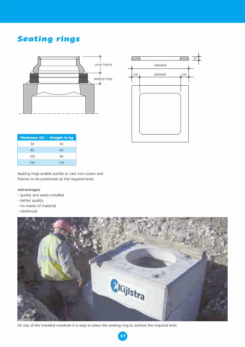
Seating rings
Seating rings enable ductile or cast iron covers and frames to be positioned at the required level.
Advantages- quickly and easily installed- better quality- no waste of material- reinforced
Thickness (D) Weight in kg
50 43
80 69
100 86
150 129
On top of the installed manhole it is easy to place the seating ring to achieve the required level.
17
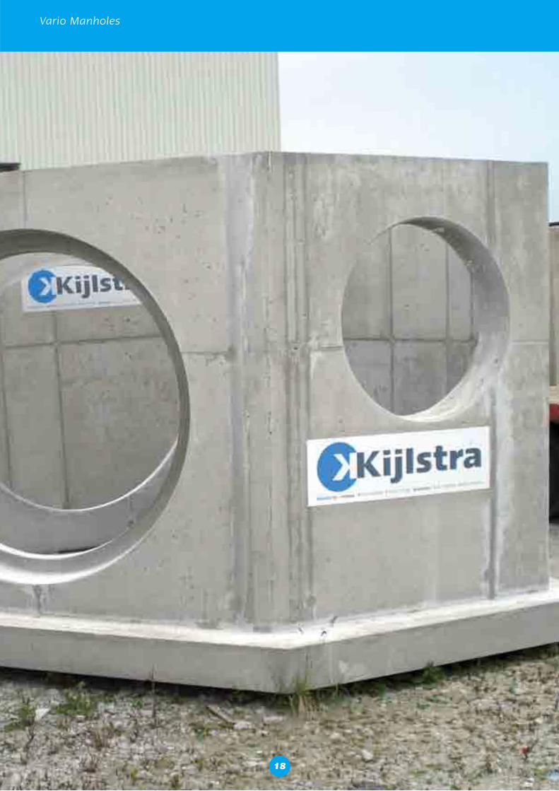
Vario Manholes
18
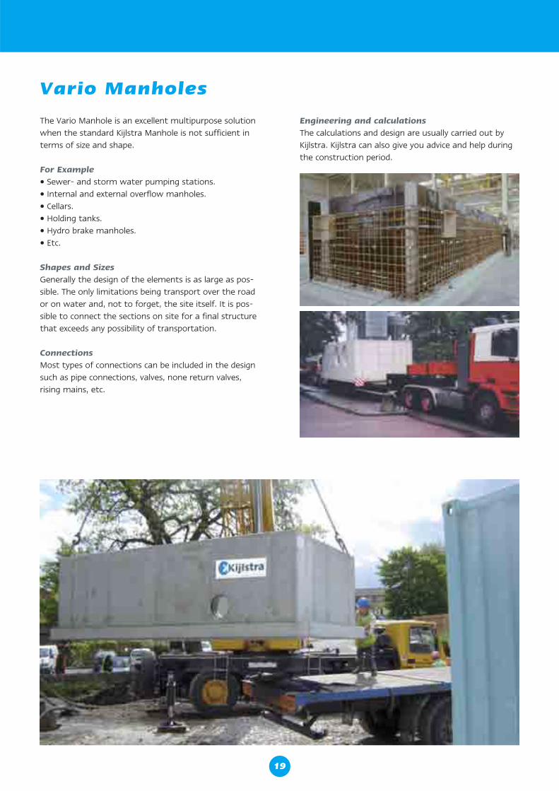
Vario Manholes
The Vario Manhole is an excellent multipurpose solution when the standard Kijlstra Manhole is not sufficient in terms of size and shape. For Example• Sewer- and storm water pumping stations.• Internal and external overflow manholes.• Cellars.• Holding tanks.• Hydro brake manholes.• Etc.
Shapes and SizesGenerally the design of the elements is as large as pos-sible. The only limitations being transport over the road or on water and, not to forget, the site itself. It is pos-sible to connect the sections on site for a final structure that exceeds any possibility of transportation.
ConnectionsMost types of connections can be included in the design such as pipe connections, valves, none return valves, rising mains, etc.
Engineering and calculationsThe calculations and design are usually carried out by Kijlstra. Kijlstra can also give you advice and help during the construction period.
19
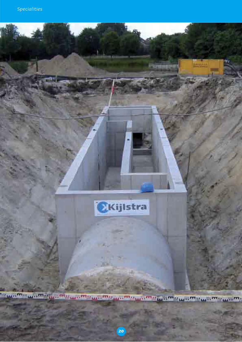
Specialities
20
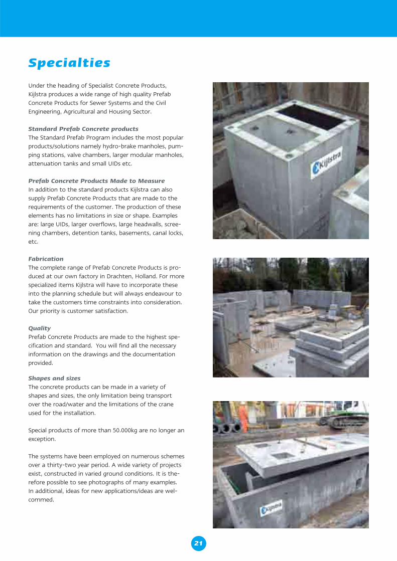
Under the heading of Specialist Concrete Products, Kijlstra produces a wide range of high quality Prefab Concrete Products for Sewer Systems and the Civil Engineering, Agricultural and Housing Sector.
Standard Prefab Concrete productsThe Standard Prefab Program includes the most popular products/solutions namely hydro-brake manholes, pum-ping stations, valve chambers, larger modular manholes, attenuation tanks and small UIDs etc.
Prefab Concrete Products Made to MeasureIn addition to the standard products Kijlstra can also supply Prefab Concrete Products that are made to the requirements of the customer. The production of these elements has no limitations in size or shape. Examples are: large UIDs, larger overflows, large headwalls, scree-ning chambers, detention tanks, basements, canal locks, etc.
FabricationThe complete range of Prefab Concrete Products is pro-duced at our own factory in Drachten, Holland. For more specialized items Kijlstra will have to incorporate these into the planning schedule but will always endeavour to take the customers time constraints into consideration. Our priority is customer satisfaction.
QualityPrefab Concrete Products are made to the highest spe-cification and standard. You will find all the necessary information on the drawings and the documentation provided.
Shapes and sizesThe concrete products can be made in a variety of shapes and sizes, the only limitation being transport over the road/water and the limitations of the crane used for the installation.
Special products of more than 50.000kg are no longer an exception.
The systems have been employed on numerous schemes over a thirty-two year period. A wide variety of projects exist, constructed in varied ground conditions. It is the-refore possible to see photographs of many examples. In additional, ideas for new applications/ideas are wel-commed.
Specialties
21
Specialities
Attenuation sewers and manholes
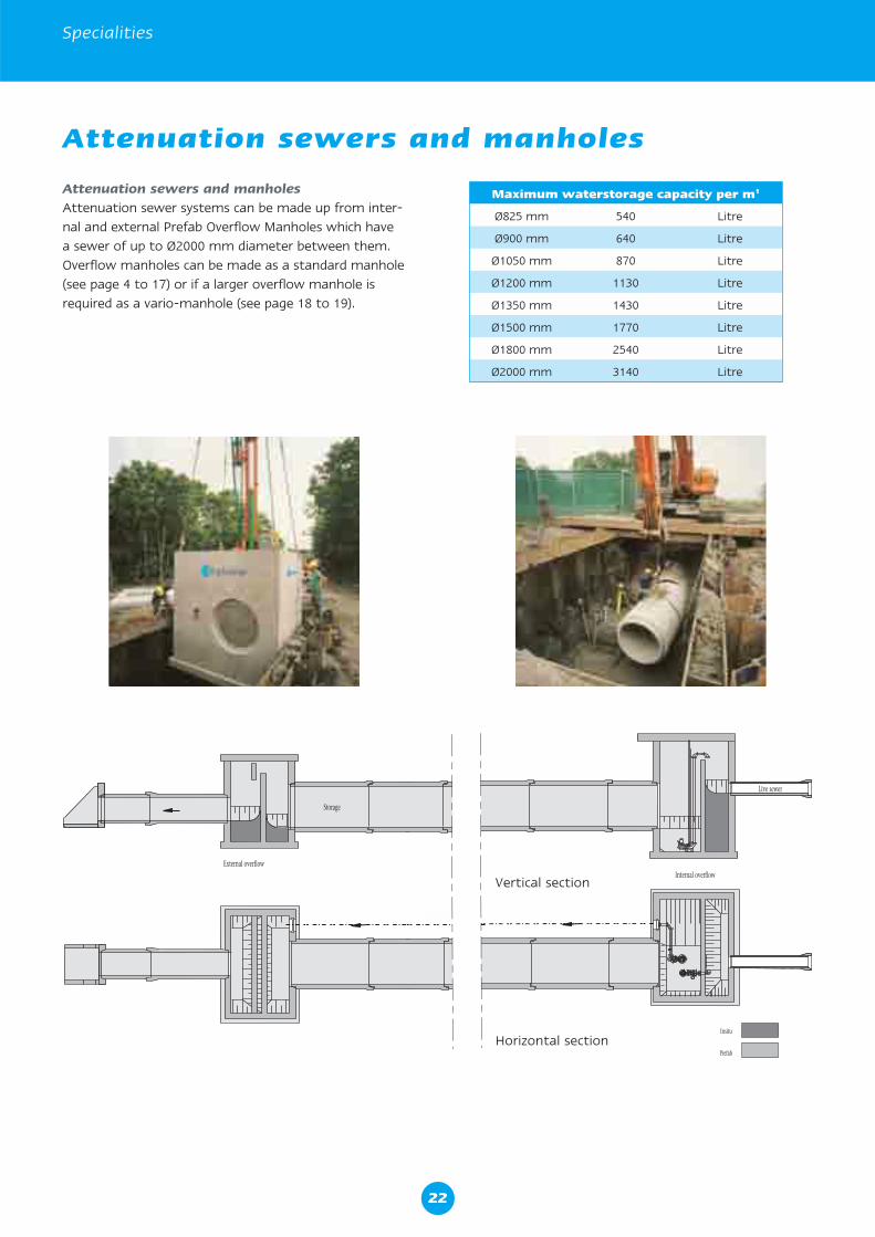
Attenuation sewers and manholesAttenuation sewer systems can be made up from inter-nal and external Prefab Overflow Manholes which have a sewer of up to Ø2000 mm diameter between them. Overflow manholes can be made as a standard manhole (see page 4 to 17) or if a larger overflow manhole is required as a vario-manhole (see page 18 to 19).
Maximum waterstorage capacity per m1
Ø825 mm 540 Litre
Ø900 mm 640 Litre
Ø1050 mm 870 Litre
Ø1200 mm 1130 Litre
Ø1350 mm 1430 Litre
Ø1500 mm 1770 Litre
Ø1800 mm 2540 Litre
Ø2000 mm 3140 Litre
Internal overflow
Live sewer
Prefab
Insitu
External overflow
Storage
Vertical section
Horizontal section
22
Reservoirs/Storage Tanks
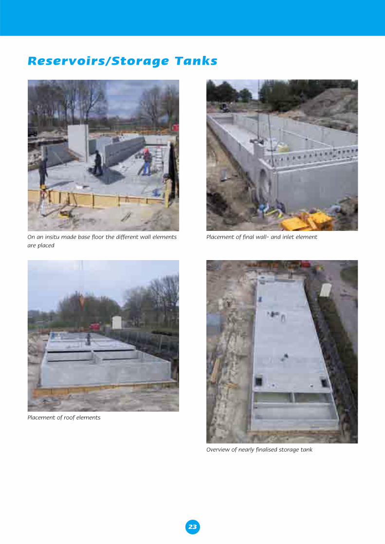
On an insitu made base floor the different wall elements are placed
Placement of roof elements
Overview of nearly finalised storage tank
Placement of final wall- and inlet element
23
Specialities
Reservoirs/Storage Tanks
Concrete prefab settlement tanks and storage reservoirs
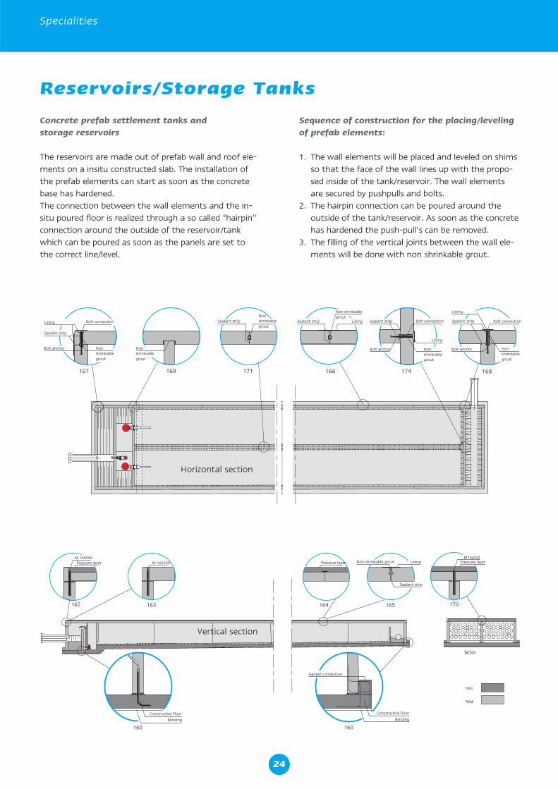
The reservoirs are made out of prefab wall and roof ele-ments on a insitu constructed slab. The installation of the prefab elements can start as soon as the concrete base has hardened.The connection between the wall elements and the in-situ poured floor is realized through a so called “hairpin’’ connection around the outside of the reservoir/tank which can be poured as soon as the panels are set to the correct line/level.
Vertical section
Horizontal section
Sequence of construction for the placing/leveling of prefab elements:
1. The wall elements will be placed and leveled on shims so that the face of the wall lines up with the propo-sed inside of the tank/reservoir. The wall elements are secured by pushpulls and bolts.
2. The hairpin connection can be poured around the outside of the tank/reservoir. As soon as the concrete has hardened the push-pull’s can be removed.
3. The filling of the vertical joints between the wall ele-ments will be done with non shrinkable grout.
24
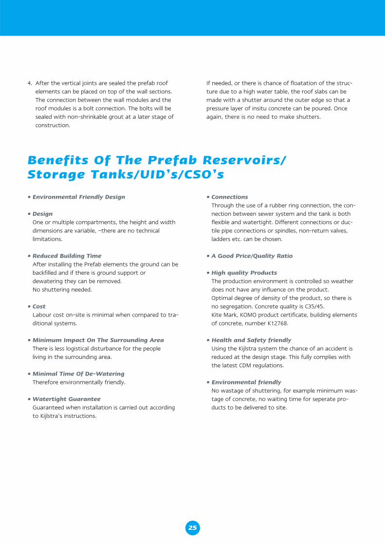
• Environmental Friendly Design
• Design One or multiple compartments, the height and width
dimensions are variable, –there are no technical limitations.
• Reduced Building Time After installing the Prefab elements the ground can be backfilled and if there is ground support or dewatering they can be removed. No shuttering needed.
• Cost Labour cost on-site is minimal when compared to tra-
ditional systems.
• Minimum Impact On The Surrounding Area There is less logistical disturbance for the people living in the surrounding area.
• Minimal Time Of De-Watering Therefore environmentally friendly.
• Watertight Guarantee Guaranteed when installation is carried out according
to Kijlstra’s instructions.
• Connections Through the use of a rubber ring connection, the con-
nection between sewer system and the tank is both flexible and watertight. Different connections or duc-tile pipe connections or spindles, non-return valves, ladders etc. can be chosen.
• A Good Price/Quality Ratio
• High quality Products The production environment is controlled so weather does not have any influence on the product. Optimal degree of density of the product, so there is no segregation. Concrete quality is C35/45. Kite Mark, KOMO product certificate, building elements
of concrete, number K12768.
• Health and Safety friendly Using the Kijlstra system the chance of an accident is
reduced at the design stage. This fully complies with the latest CDM regulations.
• Environmental friendly No wastage of shuttering, for example minimum was-
tage of concrete, no waiting time for seperate pro-ducts to be delivered to site.
Benefits Of The Prefab Reservoirs/Storage Tanks/UID’s/CSO’s
4. After the vertical joints are sealed the prefab roof elements can be placed on top of the wall sections. The connection between the wall modules and the roof modules is a bolt connection. The bolts will be sealed with non-shrinkable grout at a later stage of construction.
If needed, or there is chance of floatation of the struc-ture due to a high water table, the roof slabs can be made with a shutter around the outer edge so that a pressure layer of insitu concrete can be poured. Once again, there is no need to make shutters.
25
Specialities
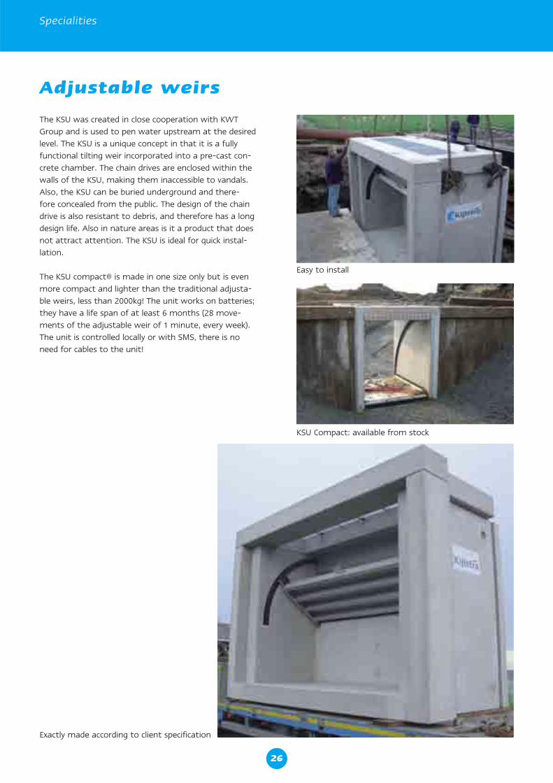
Adjustable weirs
The KSU was created in close cooperation with KWT Group and is used to pen water upstream at the desired level. The KSU is a unique concept in that it is a fully functional tilting weir incorporated into a pre-cast con-crete chamber. The chain drives are enclosed within the walls of the KSU, making them inaccessible to vandals. Also, the KSU can be buried underground and there-fore concealed from the public. The design of the chain drive is also resistant to debris, and therefore has a long design life. Also in nature areas is it a product that does not attract attention. The KSU is ideal for quick instal-lation.
The KSU compact® is made in one size only but is even more compact and lighter than the traditional adjusta-ble weirs, less than 2000kg! The unit works on batteries; they have a life span of at least 6 months (28 move-ments of the adjustable weir of 1 minute, every week). The unit is controlled locally or with SMS, there is no need for cables to the unit!
Easy to install
KSU Compact: available from stock
Exactly made according to client specification
26
300 150
500
100 100800
1000
100
50
100
690
4030
100
Ø D
n
Ø D
n
140 320 140
600
100 400 100
bob
1:2
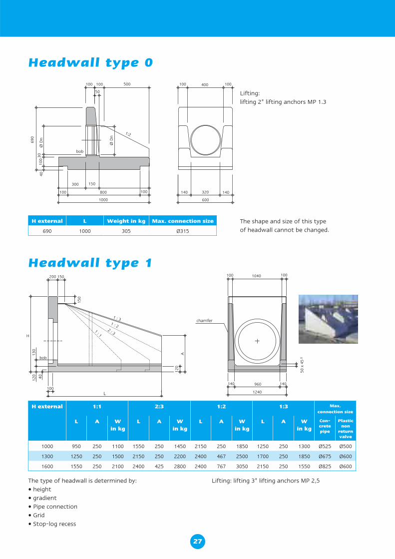
Headwall type 0
H external L Weight in kg Max. connection size
690 1000 305 Ø315
The shape and size of this type of headwall cannot be changed.
Lifting: lifting 2” lifting anchors MP 1.3
200 150
150
H
130
100
bob
120 40
A12
0
100 1001040
chamfer
960
1240
50 x
45
0
140140
1 : 31 : 2
2 : 31 : 1
H external 1:1 2:3 1:2 1:3 Max. connection size
L A Win kg
L A Win kg
L A Win kg
L A Win kg
Con-cretepipe
Plasticnon
returnvalve
1000 950 250 1100 1550 250 1450 2150 250 1850 1250 250 1300 Ø525 Ø500
1300 1250 250 1500 2150 250 2200 2400 467 2500 1700 250 1850 Ø675 Ø600
1600 1550 250 2100 2400 425 2800 2400 767 3050 2150 250 1550 Ø825 Ø600
The type of headwall is determined by:• height• gradient• Pipe connection• Grid• Stop-log recess
Lifting: lifting 3” lifting anchors MP 2,5
Headwall type 1
27
Headwall
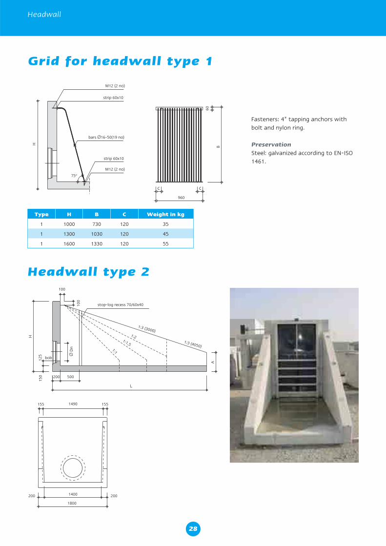
Headwall type 2100
200 500
L
100
H
125
A
150
stop-log recess 70/60x40
1:3 (4050)
1:3 (3000)1:2
1:1,5
1:1
bob
Ø D
n
1400
1800
200 200
1490155 155
M12 (2 no)
strip 60x10
bars Ø16-50(19 no)
strip 60x10
M12 (2 no)
960
c c
60
B
750
H
Grid for headwall type 1
Type H B C Weight in kg
1 1000 730 120 35
1 1300 1030 120 45
1 1600 1330 120 55
Fasteners: 4” tapping anchors with bolt and nylon ring.
PreservationSteel: galvanized according to EN-ISO 1461.
28
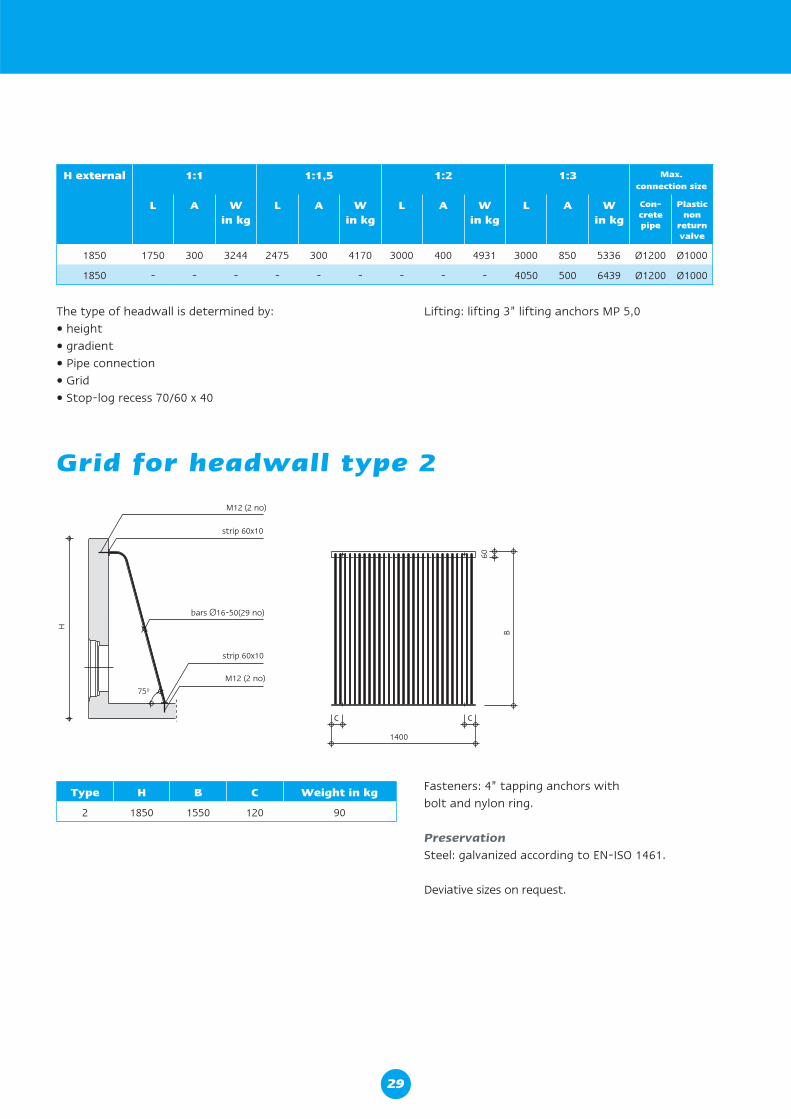
Grid for headwall type 2
H external 1:1 1:1,5 1:2 1:3 Max. connection size
L A Win kg
L A Win kg
L A Win kg
L A Win kg
Con-cretepipe
Plasticnon
returnvalve
1850 1750 300 3244 2475 300 4170 3000 400 4931 3000 850 5336 Ø1200 Ø1000
1850 - - - - - - - - - 4050 500 6439 Ø1200 Ø1000
The type of headwall is determined by:• height• gradient• Pipe connection• Grid• Stop-log recess 70/60 x 40
Lifting: lifting 3” lifting anchors MP 5,0
Fasteners: 4” tapping anchors with bolt and nylon ring.
PreservationSteel: galvanized according to EN-ISO 1461.
Deviative sizes on request.
M12 (2 no)
strip 60x10
bars Ø16-50(29 no)
strip 60x10
M12 (2 no)
1400
c c
60
B
750
H
Type H B C Weight in kg
2 1850 1550 120 90
29
Kijlstra Precast and the Environment
Kijlstra Precast and the Environment
Kijlstra recognizes the impact construction has on the environment and does not want to compromise this for future generations. We will therefore utilize the latest technologies in precast construction to reduce the impact to the environment. On top of that Kijlstra has developed their system so that it will also benefit the environment in the long term.
Short term benefits:• Reduction in waste; no further need for loose
materials.• Reduction in use of plant.• Reduction in impact on community through reduced
construction period.• Reduction in use of concrete; by designing highly engi-
neered concrete, we produce lighter structures with less concrete and therefore less cement.
• By adding cement substitutes, some of which are by-products of other industries, we have reduced cement content by approximately 40% while still achieving very high strength mixes.
• Less vehicle movements to and from site.
Long term benefits:• The structures are 100% watertight; clean water will
not leak into the system which would require cleaning at a Waste Water Treatment Works and foul water does not leak out of the system, so it cannot conta-minate the ground, ground water and other biological elements.
• Long design life.• Fully recyclable; the units consist of fully recyclable
materials.
Kijlstra is continuously reviewing and updating the system and production processes to improve the system wherever possible. This can be due to legislation changes or to new techniques in the precast industry.
30


Kijlstra LTD Riley Court, University of Warwick Science Park, Milburn Hill Road, Coventry, CV4 7HP, United Kingdom
T +44 (0)24 76323224 F +44 (0)24 76323225 I www.kijlstra.co.uk E [email protected]