Embed Size (px)
Citation preview
406 seriesAxial Piston
Fixed displacement Motor
Swashplate design
Technical Catalogue
PSM-Hydraulics04/2010

2
406 seriesFixed Displacement Axial Piston Motor
Contents
406 series hydraulic motors description. .............................................................................................................................................................................................................. 4Hydrostatic transmission hydraulic circuit diagram. ...................................................................................................................................................................................... 5Ordering Code....................................................................................................................................................................................................................................................................... 6Technical characteristics. ................................................................................................................................................................................................................................................ 7Hydraulic motor nominal size determination .................................................................................................................................................................................................. 7Working fluid requirements. ......................................................................................................................................................................................................................................... 8Allowed radial and axial loads on shaft. ................................................................................................................................................................................................................ 8Loop flushing valve and purge relief valve. ......................................................................................................................................................................................................... 9Safety valves. .........................................................................................................................................................................................................................................................................10Overall-mounting dimensions. Size range 71, 90 cm3. ..............................................................................................................................................................................11
Main dimensions. ..........................................................................................................................................................................................................................................................11Hydraulic motor versions. ........................................................................................................................................................................................................................................12Shaft ends. .........................................................................................................................................................................................................................................................................14
Overall-mounting dimensions. Size range 110, 125 cm3. .........................................................................................................................................................................15Main dimensions. ..........................................................................................................................................................................................................................................................15Hydraulic motors versions. ......................................................................................................................................................................................................................................16Shaft ends. .........................................................................................................................................................................................................................................................................18
Standard program. ............................................................................................................................................................................................................................................................19Hydraulic motor direction and drain pipe mounting scheme. ...........................................................................................................................................................20
3
Technical Catalogue
General information
406 series hydraulic motors – worldwide usage product, designed for the global market.
406 series hydraulic motors are intended for operation in hydrostatic transmissions (HST). Hydraulic motors transform the working fluid energy into the mechanical energy of the shaft rotation.Hydraulic motor shaft rotation direction is determined by working fluid input direction.Shaft rotation frequency is determined by fluid flow volume. Created torque on hydraulic motor shaft is determined by the working fluid pressure.
Intended for use in mobile and stationary installations in set with HST.
Fixed displacement swashplate axial-piston machines.
406 series hydraulic motors have the following working displacements: 406.0.71 - 71 cm3
406.0.90 - 90 cm3
406.0.110 - 110 cm3
406.0.125 - 125 cm3
max - 400 barpeak - 450 bar
mounting flanges - SAE C (Ø127 mm) 4 bolt
operating pressure ports - SAE 1” 3000psi - SAE 1” 6000psi
case drain ports - as per ISO 9974-1 / DIN 3952-1 - as per ISO 11926-1
spline shafts - 1 1/2” 23Т 16/32DP ANSI B92.1a - 1 3/8” 21Т 16/32DP ANSI B92.1a - W35x2x30x16x9g DIN 5480 - W40x2x30x18x9g DIN 5480 - W45x2x30x21x9g DIN 5480 - loop flushing valve - purge relief valve
- shaft speed sensor - pressure-relief valves
Purpose
Application
Design
Size range
Operating pressure
Connection
Built-on options
Requirement options
4
406 seriesFixed Displacement Axial Piston Motor
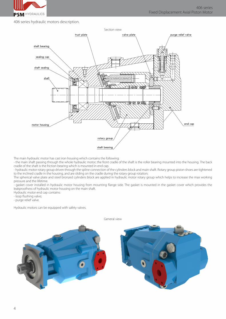
406 series hydraulic motors description.
Section view
The main hydraulic motor has cast iron housing which contains the following:- the main shaft passing through the whole hydraulic motor; the front cradle of the shaft is the roller bearing mounted into the housing. The back cradle of the shaft is the friction bearing which is mounted in end cap.- hydraulic motor rotary group driven through the spline connection of the cylinders block and main shaft. Rotary group piston shoes are tightened to the inclined cradle in the housing, and are sliding on the cradle during the rotary group rotation;The spherical valve plate and steel bronzed cylinders block are applied in hydraulic motor rotary group which helps to increase the max working pressure and the lifetime. - gasket cover installed in hydraulic motor housing from mounting flange side. The gasket is mounted in the gasket cover which provides the leakproofness of hydraulic motor housing on the main shaft.Hydraulic motor end cap contains:- loop flushing valve;- purge relief valve.
Hydraulic motors can be equipped with safety valves.
General view
5
Technical Catalogue
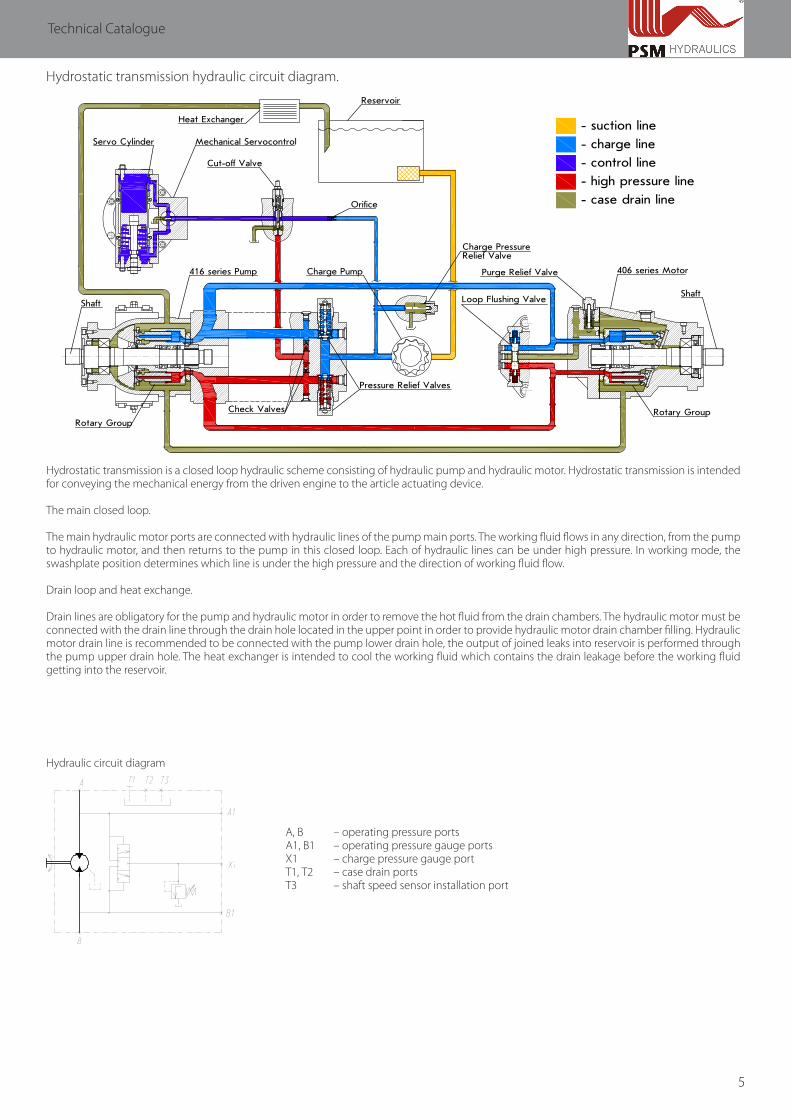
Hydrostatic transmission hydraulic circuit diagram.
- suction line
- charge line
- control line
- high pressure line
- case drain line
Heat Exchanger
Reservoir
Servo Cylinder Mechanical Servocontrol
Cut-off Valve
406 series MotorCharge Pump
Pressure Relief Valves
Shaft
Rotary GroupCheck Valves
Shaft
416 series Pump
Rotary Group
Loop Flushing Valve
Charge PressureRelief Valve
Orifice
Purge Relief Valve
Hydrostatic transmission is a closed loop hydraulic scheme consisting of hydraulic pump and hydraulic motor. Hydrostatic transmission is intended for conveying the mechanical energy from the driven engine to the article actuating device.
The main closed loop.
The main hydraulic motor ports are connected with hydraulic lines of the pump main ports. The working fluid flows in any direction, from the pump to hydraulic motor, and then returns to the pump in this closed loop. Each of hydraulic lines can be under high pressure. In working mode, the swashplate position determines which line is under the high pressure and the direction of working fluid flow.
Drain loop and heat exchange.
Drain lines are obligatory for the pump and hydraulic motor in order to remove the hot fluid from the drain chambers. The hydraulic motor must be connected with the drain line through the drain hole located in the upper point in order to provide hydraulic motor drain chamber filling. Hydraulic motor drain line is recommended to be connected with the pump lower drain hole, the output of joined leaks into reservoir is performed through the pump upper drain hole. The heat exchanger is intended to cool the working fluid which contains the drain leakage before the working fluid getting into the reservoir.
Hydraulic circuit diagram
А, В – operating pressure portsА1, В1 – operating pressure gauge portsХ1 – charge pressure gauge portТ1, Т2 – case drain portsТ3 – shaft speed sensor installation port
6
406 seriesFixed Displacement Axial Piston Motor
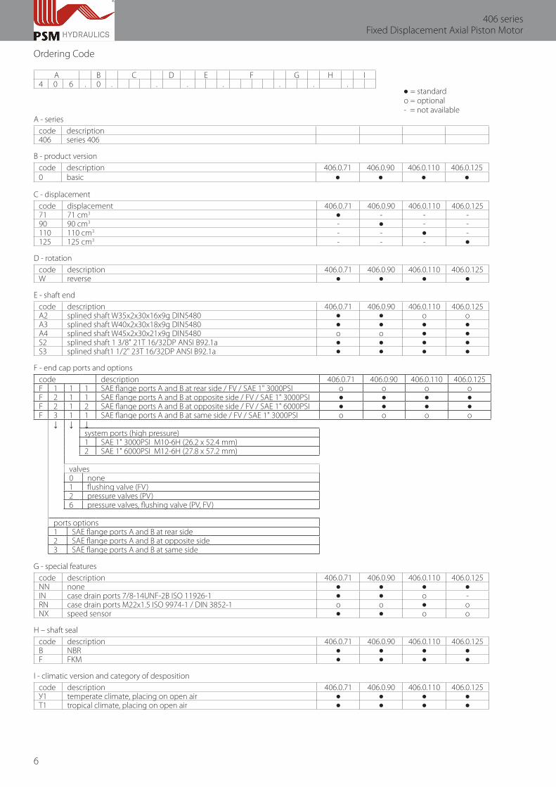
Ordering Code
A B C D E F G H I4 0 6 . 0 . . . . . . .
● = standard о = optional - = not availableA - series
code description406 series 406
B - product versioncode description 406.0.71 406.0.90 406.0.110 406.0.1250 basic ● ● ● ●
С - displacementcode displacement 406.0.71 406.0.90 406.0.110 406.0.12571 71 cm3 ● - - -90 90 cm3 - ● - -110 110 cm3 - - ● -125 125 cm3 - - - ●
D - rotationcode description 406.0.71 406.0.90 406.0.110 406.0.125W reverse ● ● ● ●
E - shaft endcode description 406.0.71 406.0.90 406.0.110 406.0.125А2 splined shaft W35x2x30x16x9g DIN5480 ● ● о оА3 splined shaft W40x2x30x18x9g DIN5480 ● ● ● ●А4 splined shaft W45x2x30x21x9g DIN5480 о о ● ●S2 splined shaft 1 3/8" 21Т 16/32DP ANSI B92.1a ● ● ● ●S3 splined shaft1 1/2" 23Т 16/32DP ANSI B92.1a ● ● ● ●
F - end cap ports and optionscode description 406.0.71 406.0.90 406.0.110 406.0.125F 1 1 1 SAE flange ports A and B at rear side / FV / SAE 1" 3000PSI о о о оF 2 1 1 SAE flange ports A and B at opposite side / FV / SAE 1" 3000PSI ● ● ● ●F 2 1 2 SAE flange ports A and B at opposite side / FV / SAE 1" 6000PSI ● ● ● ●F 3 1 1 SAE flange ports A and B at same side / FV / SAE 1" 3000PSI о о о о
↓ ↓ ↓system ports (high pressure)1 SAE 1" 3000PSI М10-6Н (26.2 х 52.4 mm)2 SAE 1" 6000PSI М12-6Н (27.8 х 57.2 mm)
valves0 none1 flushing valve (FV)2 pressure valves (PV)6 pressure valves, flushing valve (PV, FV)
ports options1 SAE flange ports A and B at rear side2 SAE flange ports A and B at opposite side3 SAE flange ports A and B at same side
G - special featurescode description 406.0.71 406.0.90 406.0.110 406.0.125NN none ● ● ● ●IN case drain ports 7/8-14UNF-2B ISO 11926-1 ● ● о -RN case drain ports M22x1.5 ISO 9974-1 / DIN 3852-1 o o ● oNX speed sensor ● ● о о
H – shaft sealcode description 406.0.71 406.0.90 406.0.110 406.0.125B NBR ● ● ● ●F FKM ● ● ● ●
I - climatic version and category of despositioncode description 406.0.71 406.0.90 406.0.110 406.0.125У1 temperate climate, placing on open air ● ● ● ●Т1 tropical climate, placing on open air ● ● ● ●

7
Technical Catalogue
Technical characteristics.
Size range 406.0.71 406.0.90 406.0.110 406.0.125Working displacement V
g, cm3 71 90 110 125
Shaft rotation speed n, rpm- min n
min50 50 50 50
- nominal nnom
2000 2000 2000 2000- max n
max, at input pressure 0.8 bar 3050 3050 3000 3000
- peak npeak
, at input pressure 2 bar 3300 3300 3200 3200Flow Q, l/min- min Q
min3.74 4.74 5.79 6.58
- nominal Qnom
149.47 189.47 173.68 197.37- max Q
max227.95 288.95 347.37 394.74
- peak Qpeak
246.63 312.63 370.53 421.05Working pressure (difference) ∆P, bar- nominal ∆P
nom250 250 250 250
- max working ∆Pmax
400 400 400 400- peak ∆P
peak450 450 450 450
Purge relief valve adjustment pressure Pn, bar 23 23 23 23
Drain pressure Pdr
, bar- max working 2.5 2.5 2.5 2.5- max short-term (t<5 min) 5 5 5 5Effective power N, kW- nominal N
nom (at n
nom, P
nom) 56.05 71.05 65.13 74.01
- max Nmax
(at nmax
, Pmax
) 136.77 173.37 208.42 236.84- peak N
peak (at n
peak, P
peak) 166.47 211.02 250.10 284.21
Torque T, Nm- nominal Т
nom (at P
nom) 254.25 322.29 393.91 447.62
- max Tmax
(at Pmax
) 406.80 515.66 630.25 716.20- peak T
peak (at P
peak) 457.65 580.12 709.04 805.72
Volume efficiency 0.95 0.95 0.95 0.95Weight, kg 40 40 48 48
Hydraulic motor nominal size determination
Flow Q=V
g • n
l/min1000 • ηv
Torque Т=V
g • ∆P • η
mhN•m20 • π
Effective power N=Q • ∆P • η
tkW600
Rotation frequency n=Q • 1000 • η
vrpmV
g
Where:Q – flow, l/minТ – torque, N•mN – power, kWV
g – motor displacement, cm3
n – shaft rotation speed, rpm∆P – pressure difference, barη
v – volume efficiency
ηmh
– hydraulic mechanical efficiencyη
t = η
v • η
mh – overall efficiency
8
406 seriesFixed Displacement Axial Piston Motor
Working fluid requirements.
Working fluid temperature:Max constant +75ºСMax peak (short-term) +100ºСMin short-term (at cold start) - 40ºС
Working fluid cinematic viscosity:optimal (constant) 20-35 mm2/sec (cSt)max startup 1500 mm2/sec (cSt)min short-term 10 mm2/sec (cSt) Working fluid purity: at least 12th class as per GOST 17216-71 at least 18/15th class as per ISO/DIN 4406
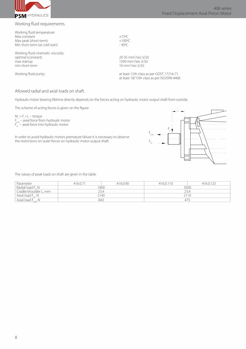
Allowed radial and axial loads on shaft.
Hydraulic motor bearing lifetime directly depends on the forces acting on hydraulic motor output shaft from outside.
The scheme of acting forces is given on the figure:
Mr = F
r • L – torque
Fout
– axial force from hydraulic motorF
in – axial force into hydraulic motor
Fr
Fout
In order to avoid hydraulic motors premature failure it is necessary to observethe restrictions on outer forces on hydraulic motor output shaft. F
in
The values of peak loads on shaft are given in the table.
Parameter 416.0.71 416.0.90 416.0.110 416.0.125Radial load F
r, N 1800 3500
Cradle/shoulder L, mm 23.4 23.4Axial load F
in, N 2140 2110
Axial load Fout
, N 843 475

9
Technical Catalogue
Loop flushing valve and purge relief valve.
Loop flushing valve is mounted in hydraulic motor end cap. Loop flushing valve design and operating principle is given on the Fig.The loop flushing valve is intended for compulsory working fluid change in power lines in order to provide the eligible temperature operating conditions of the article hydraulic system, and to provide the possibility of volume closed loop constant cleaning from wear debris. At achieving the slight pressure difference on the valve buttends, it shifts to the corresponding side and compresses the spring. The line with lower pressure (drain line) is connected with drain line into the article housing through the purge relief valve. The valve springs are compressed with plugs.
Loop flushing valve design
Purge relief valve is intended for maintaining the control and charge pressure in machine hydraulic system at loop flushing valve actuation.At achieving the adjustment pressure the force on the valve buttend is compressing the spring and is connecting the drain line with the article drain line through the loop flushing valve maintaining the control and charge pressure. The valve actuation pressure is adjusted by spring compression with the valve threaded body.
The purge relief valve adjustment pressure = 23+1 bar (by default).
The pressure is adjusted at:- motor shaft speed n = 1500 rpm;- working fluid temperature in the loop t = +45…50ºС.
The charge pressure is adjusted in negotiation with the customer.
Hydraulic circuit diagram
10
406 seriesFixed Displacement Axial Piston Motor
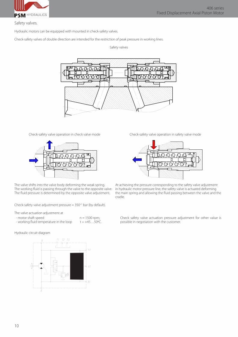
Safety valves.
Hydraulic motors can be equipped with mounted in check-safety valves.
Check-safety valves of double direction are intended for the restriction of peak pressure in working lines.
Safety valves
Check-safety valve operation in check valve mode Check-safety valve operation in safety valve mode
The valve shifts into the valve body deforming the weak spring. At achieving the pressure corresponding to the safety valve adjustmentThe working fluid is passing through the valve to the opposite valve. in hydraulic motor pressure line, the safety valve is actuated deformingThe fluid pressure is determined by the opposite valve adjustment. the main spring and allowing the fluid passing between the valve and the cradle.
Check-safety valve adjustment pressure = 350+5 bar (by default).
The valve actuation adjustment at- motor shaft speed n = 1500 rpm;- working fluid temperature in the loop t = +45…50ºС.
Check safety valve actuation pressure adjustment for other value is possible in negotiation with the customer.
Hydraulic circuit diagram

11
Technical Catalogue
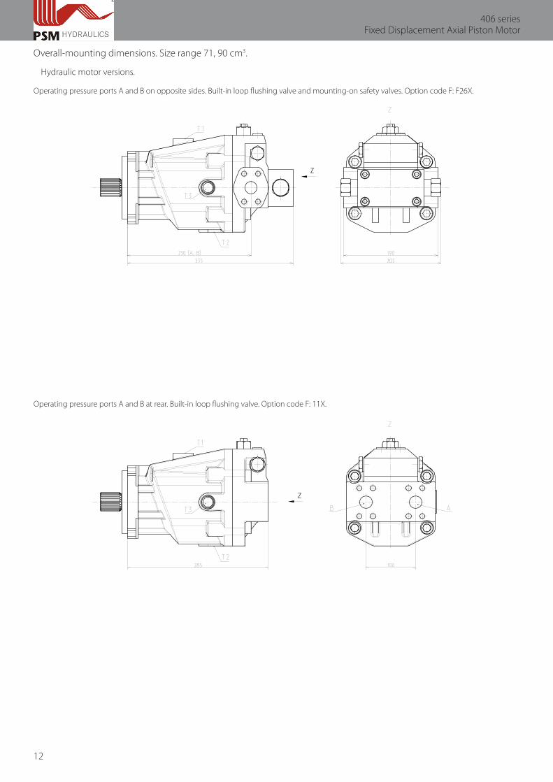
Overall-mounting dimensions. Size range 71, 90 cm3.
Main dimensions.
option codeА, В
Т1, Т2
A1, B2X1
operating pressure ports
case drain ports
operating pressure gauge portscharge pressure gauge port
SAE 1” 3000psiSAE 1” 6000psiM22x1.5-15, GOST 25064 / ISO 6149-17/8-14UNF-2B, ISO 11926-1M22x1.5-26, DIN 3852-1 / ISO 9974-1M12x1.5-12, GOST 25065 / ISO 6149-1M12x1.5-14, GOST 25065 / ISO 6149-1
FF-GG--
Fxx1Fxx2standard programINRNstandard programstandard program
12
406 seriesFixed Displacement Axial Piston Motor
Overall-mounting dimensions. Size range 71, 90 cm3.
Hydraulic motor versions.
Operating pressure ports A and B on opposite sides. Built-in loop flushing valve and mounting-on safety valves. Option code F: F26Х.
Operating pressure ports A and B at rear. Built-in loop flushing valve. Option code F: 11Х.
13
Technical Catalogue
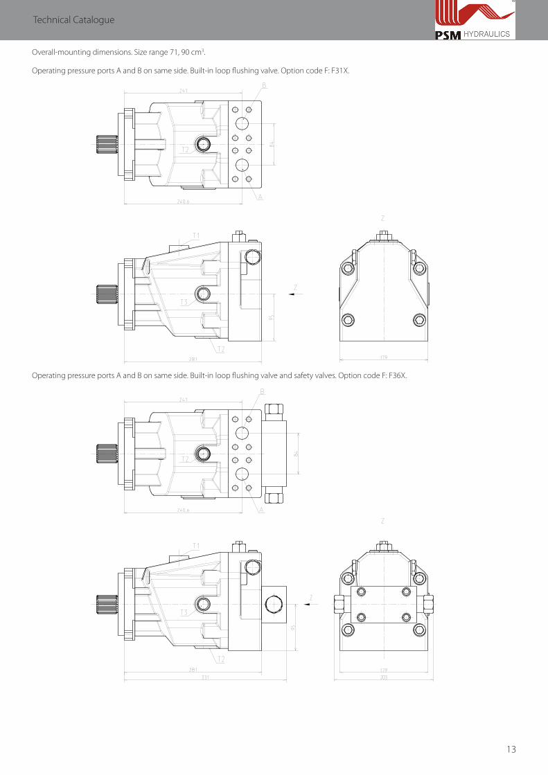
Overall-mounting dimensions. Size range 71, 90 cm3.
Operating pressure ports A and B on same side. Built-in loop flushing valve. Option code F: F31Х.
Operating pressure ports A and B on same side. Built-in loop flushing valve and safety valves. Option code F: F36Х.
14
406 seriesFixed Displacement Axial Piston Motor
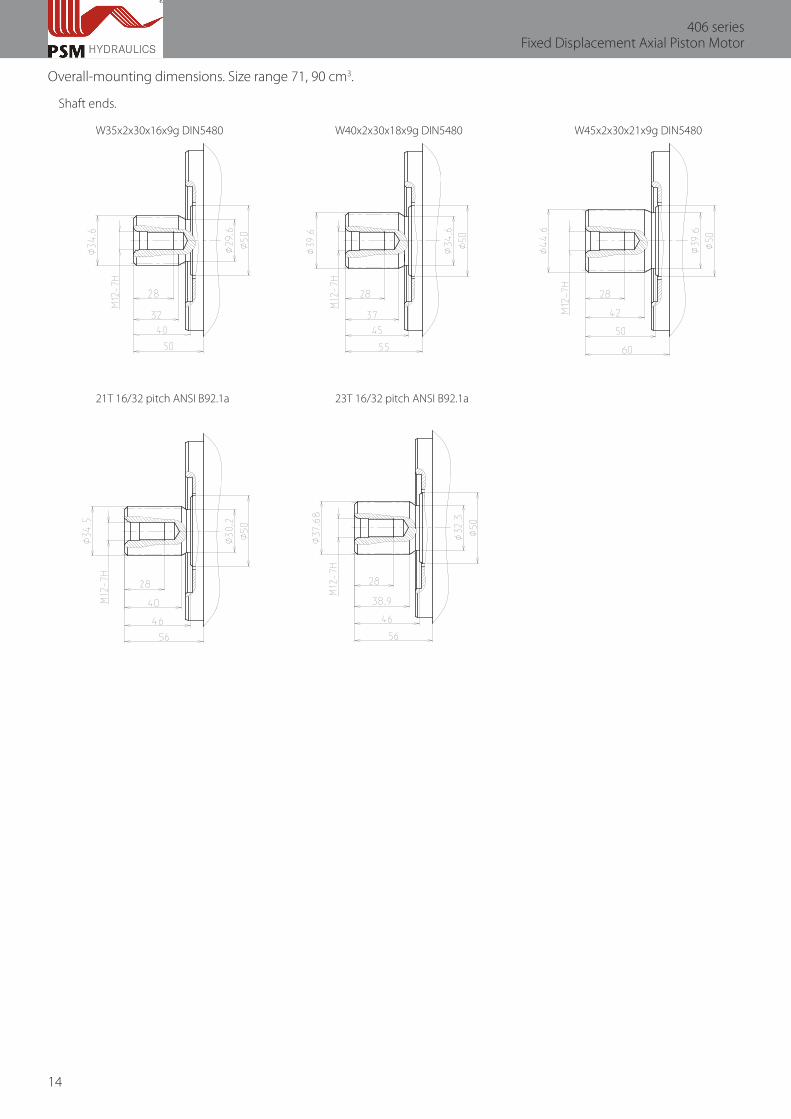
Overall-mounting dimensions. Size range 71, 90 cm3.
Shaft ends.
W35x2x30x16x9g DIN5480 W40x2x30x18x9g DIN5480 W45x2x30x21x9g DIN5480
21T 16/32 pitch ANSI B92.1a 23T 16/32 pitch ANSI B92.1a
15
Technical Catalogue
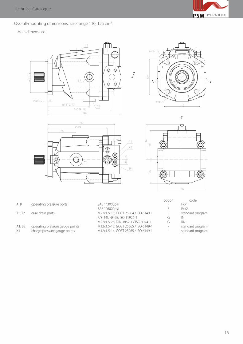
Overall-mounting dimensions. Size range 110, 125 cm3.
Main dimensions.
option codeА, В
Т1, Т2
A1, B2X1
operating pressure ports
case drain ports
operating pressure gauge pointscharge pressure gauge points
SAE 1” 3000psiSAE 1” 6000psiM22x1.5-15, GOST 25064 / ISO 6149-17/8-14UNF-2B, ISO 11926-1M22x1.5-26, DIN 3852-1 / ISO 9974-1M12x1.5-12, GOST 25065 / ISO 6149-1M12x1.5-14, GOST 25065 / ISO 6149-1
FF-GG--
Fxx1Fxx2standard programINRNstandard programstandard program

16
406 seriesFixed Displacement Axial Piston Motor
Overall-mounting dimensions. Size range 110, 125 cm3.
Hydraulic motors versions.
Operating pressure ports A and B on opposite sides. Built-in loop flushing valve and mounting-on safety valves. Option code F: F26Х.
Operating pressure ports A and B at rear. Built-in loop flushing valve. Option code F: 11Х.
17
Technical Catalogue
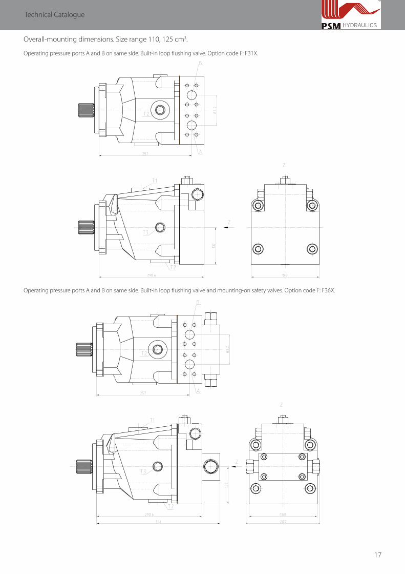
Overall-mounting dimensions. Size range 110, 125 cm3.
Operating pressure ports A and B on same side. Built-in loop flushing valve. Option code F: F31Х.
Operating pressure ports A and B on same side. Built-in loop flushing valve and mounting-on safety valves. Option code F: F36Х.

18
406 seriesFixed Displacement Axial Piston Motor
Overall-mounting dimensions. Size range 110, 125 cm3.
Shaft ends. W35x2x30x16x9g DIN5480 W40x2x30x18x9g DIN5480 W45x2x30x21x9g DIN5480
21T 16/32 pitch ANSI B92.1a 23T 16/32 pitch ANSI B92.1a

19
Technical Catalogue
Standard program.
406.0.71.W.S3.F211.NN.B.У1 406.0.90.W.S3.F211.NN.B.У1 406.0.110.W.S3.F211.NN.B.У1 406.0.125.W.S3.F211.NN.B.У1406.0.71.W.S2.F211.NN.B.У1 406.0.90.W.S2.F211.NN.B.У1 406.0.110.W.S2.F211.NN.B.У1 406.0.125.W.S2.F211.NN.B.У1406.0.71.W.А4.F211.NN.B.У1 406.0.90.W.А4.F211.NN.B.У1 406.0.110.W.А4.F211.NN.B.У1 406.0.125.W.А4.F211.NN.B.У1406.0.71.W.А2.F211.NN.B.У1 406.0.90.W.А2.F211.NN.B.У1 406.0.110.W.А2.F211.NN.B.У1 406.0.125.W.А2.F211.NN.B.У1406.0.71.W.S3.F212.NN.B.У1 406.0.90.W.S3.F212.NN.B.У1 406.0.110.W.S3.F212.NN.B.У1 406.0.125.W.S3.F212.NN.B.У1406.0.71.W.S2.F212.NN.B.У1 406.0.90.W.S2.F212.NN.B.У1 406.0.110.W.S2.F212.NN.B.У1 406.0.125.W.S2.F212.NN.B.У1406.0.71.W.А4.F212.NN.B.У1 406.0.90.W.А4.F212.NN.B.У1 406.0.110.W.А4.F212.NN.B.У1 406.0.125.W.А4.F212.NN.B.У1406.0.71.W.А2.F212.NN.B.У1 406.0.90.W.А2.F212.NN.B.У1 406.0.110.W.А2.F212.NN.B.У1 406.0.125.W.А2.F212.NN.B.У1406.0.71.W.S3.F211.IN.B.У1 406.0.90.W.S3.F211.IN.B.У1 406.0.110.W.S3.F211.IN.B.У1 406.0.125.W.S3.F211.IN.B.У1406.0.71.W.S2.F211.IN.B.У1 406.0.90.W.S2.F211.IN.B.У1 406.0.110.W.S2.F211.IN.B.У1 406.0.125.W.S2.F211.IN.B.У1406.0.71.W.А4.F211.IN.B.У1 406.0.90.W.А4.F211.IN.B.У1 406.0.110.W.А4.F211.IN.B.У1 406.0.125.W.А4.F211.IN.B.У1406.0.71.W.А2.F211.IN.B.У1 406.0.90.W.А2.F211.IN.B.У1 406.0.110.W.А2.F211.IN.B.У1 406.0.125.W.А2.F211.IN.B.У1406.0.71.W.S3.F212.IN.B.У1 406.0.90.W.S3.F212.IN.B.У1 406.0.110.W.S3.F212.IN.B.У1 406.0.125.W.S3.F212.IN.B.У1406.0.71.W.S2.F212.IN.B.У1 406.0.90.W.S2.F212.IN.B.У1 406.0.110.W.S2.F212.IN.B.У1 406.0.125.W.S2.F212.IN.B.У1406.0.71.W.А4.F212.IN.B.У1 406.0.90.W.А4.F212.IN.B.У1 406.0.110.W.А4.F212.IN.B.У1 406.0.125.W.А4.F212.IN.B.У1406.0.71.W.А2.F212.IN.B.У1 406.0.90.W.А2.F212.IN.B.У1 406.0.110.W.А2.F212.IN.B.У1 406.0.125.W.А2.F212.IN.B.У1406.0.71.W.S3.F211.NN.F.У1 406.0.90.W.S3.F211.NN.F.У1 406.0.110.W.S3.F211.NN.F.У1 406.0.125.W.S3.F211.NN.F.У1406.0.71.W.S2.F211.NN.F.У1 406.0.90.W.S2.F211.NN.F.У1 406.0.110.W.S2.F211.NN.F.У1 406.0.125.W.S2.F211.NN.F.У1406.0.71.W.А4.F211.NN.F.У1 406.0.90.W.А4.F211.NN.F.У1 406.0.110.W.А4.F211.NN.F.У1 406.0.125.W.А4.F211.NN.F.У1406.0.71.W.А2.F211.NN.F.У1 406.0.90.W.А2.F211.NN.F.У1 406.0.110.W.А2.F211.NN.F.У1 406.0.125.W.А2.F211.NN.F.У1406.0.71.W.S3.F212.NN.F.У1 406.0.90.W.S3.F212.NN.F.У1 406.0.110.W.S3.F212.NN.F.У1 406.0.125.W.S3.F212.NN.F.У1406.0.71.W.S2.F212.NN.F.У1 406.0.90.W.S2.F212.NN.F.У1 406.0.110.W.S2.F212.NN.F.У1 406.0.125.W.S2.F212.NN.F.У1406.0.71.W.А4.F212.NN.F.У1 406.0.90.W.А4.F212.NN.F.У1 406.0.110.W.А4.F212.NN.F.У1 406.0.125.W.А4.F212.NN.F.У1406.0.71.W.А2.F212.NN.F.У1 406.0.90.W.А2.F212.NN.F.У1 406.0.110.W.А2.F212.NN.F.У1 406.0.125.W.А2.F212.NN.F.У1406.0.71.W.S3.F211.IN.F.У1 406.0.90.W.S3.F211.IN.F.У1 406.0.110.W.S3.F211.IN.F.У1 406.0.125.W.S3.F211.IN.F.У1406.0.71.W.S2.F211.IN.F.У1 406.0.90.W.S2.F211.IN.F.У1 406.0.110.W.S2.F211.IN.F.У1 406.0.125.W.S2.F211.IN.F.У1406.0.71.W.А4.F211.IN.F.У1 406.0.90.W.А4.F211.IN.F.У1 406.0.110.W.А4.F211.IN.F.У1 406.0.125.W.А4.F211.IN.F.У1406.0.71.W.А2.F211.IN.F.У1 406.0.90.W.А2.F211.IN.F.У1 406.0.110.W.А2.F211.IN.F.У1 406.0.125.W.А2.F211.IN.F.У1406.0.71.W.S3.F212.IN.F.У1 406.0.90.W.S3.F212.IN.F.У1 406.0.110.W.S3.F212.IN.F.У1 406.0.125.W.S3.F212.IN.F.У1406.0.71.W.S2.F212.IN.F.У1 406.0.90.W.S2.F212.IN.F.У1 406.0.110.W.S2.F212.IN.F.У1 406.0.125.W.S2.F212.IN.F.У1406.0.71.W.А4.F212.IN.F.У1 406.0.90.W.А4.F212.IN.F.У1 406.0.110.W.А4.F212.IN.F.У1 406.0.125.W.А4.F212.IN.F.У1406.0.71.W.А2.F212.IN.F.У1 406.0.90.W.А2.F212.IN.F.У1 406.0.110.W.А2.F212.IN.F.У1 406.0.125.W.А2.F212.IN.F.У1406.0.71.W.S3.F211.NN.F.Т1 406.0.90.W.S3.F211.NN.F.Т1 406.0.110.W.S3.F211.NN.F.Т1 406.0.125.W.S3.F211.NN.F.Т1406.0.71.W.S2.F211.NN.F.Т1 406.0.90.W.S2.F211.NN.F.Т1 406.0.110.W.S2.F211.NN.F.Т1 406.0.125.W.S2.F211.NN.F.Т1406.0.71.W.S3.F212.NN.F.Т1 406.0.90.W.S3.F212.NN.F.Т1 406.0.110.W.S3.F212.NN.F.Т1 406.0.125.W.S3.F212.NN.F.Т1406.0.71.W.S2.F212.NN.F.Т1 406.0.90.W.S2.F212.NN.F.Т1 406.0.110.W.S2.F212.NN.F.Т1 406.0.125.W.S2.F212.NN.F.Т1
406.0.110.W.S3.F212.RN.B.У1 406.0.125.W.S3.F231.NN.B.У1406.0.125.W.S2.F361.IN.B.У1
20
406 seriesFixed Displacement Axial Piston Motor
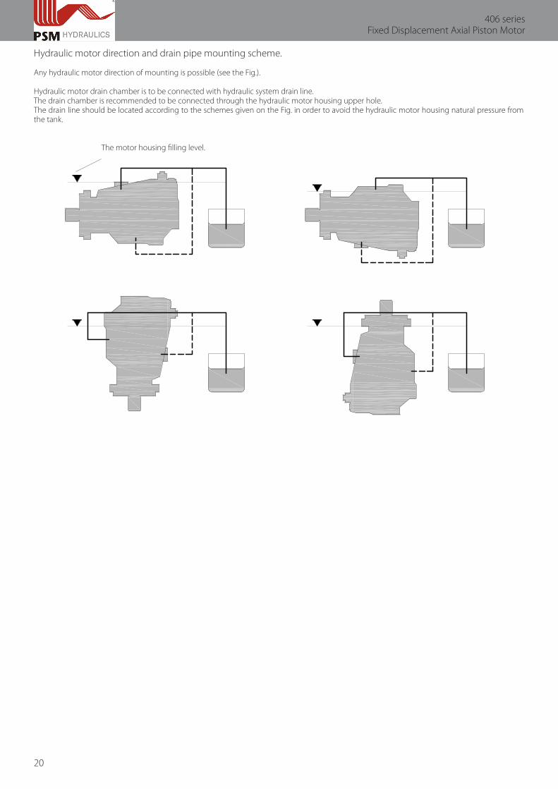
Hydraulic motor direction and drain pipe mounting scheme.
Any hydraulic motor direction of mounting is possible (see the Fig.).
Hydraulic motor drain chamber is to be connected with hydraulic system drain line.The drain chamber is recommended to be connected through the hydraulic motor housing upper hole.The drain line should be located according to the schemes given on the Fig. in order to avoid the hydraulic motor housing natural pressure from the tank.
The motor housing filling level.

21
Technical Catalogue

PSM-Hydraulics8, 1st km Sibirsky Trakt, Ekaterinburg, Russia, P.C. 620100
tel.: +7 (343) 264-66-50, fax: +7 (343) 229-79-83 web: www.psm-hydraulics.com
E-mail: [email protected]