Embed Size (px)
Citation preview

8/8/2019 406 Lesson 21
http://slidepdf.com/reader/full/406-lesson-21 1/44
Petroleum Engineering 406
Lesson 21
Wellbore Trajectory Control
8/8/2019 406 Lesson 21
http://slidepdf.com/reader/full/406-lesson-21 2/44
Lesson 18 - Wellbore Trajectory Control
Bent Motor and Bent Sub
Examples
Directional Drilling Measurements
Single Shot and Multishot
Magnetic and GyroSteering Tools
MWD tools

8/8/2019 406 Lesson 21
http://slidepdf.com/reader/full/406-lesson-21 3/44
Homework
READ: ³Applied Drilling Engineering´,
Ch. 8 (to page 390)
8/8/2019 406 Lesson 21
http://slidepdf.com/reader/full/406-lesson-21 4/44
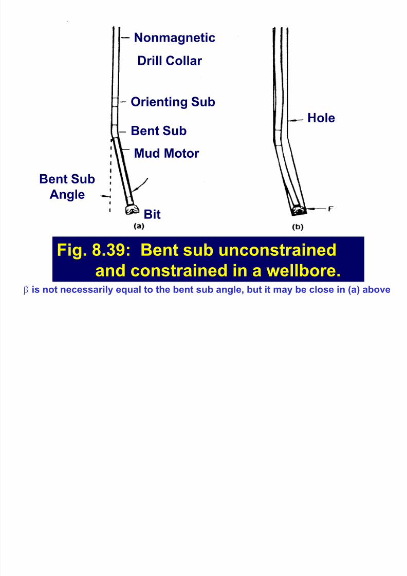
Fig. 8.39: Bent sub unconstrained
and constrained in a wellbore.
Nonmagnetic
Drill Collar
Hole
Orienting Sub
Bent Sub
Mud Motor
Bent Sub
Angle
Bit
F is not necessarily equal to the bent sub angle, but it may be close in (a) above
8/8/2019 406 Lesson 21
http://slidepdf.com/reader/full/406-lesson-21 5/44
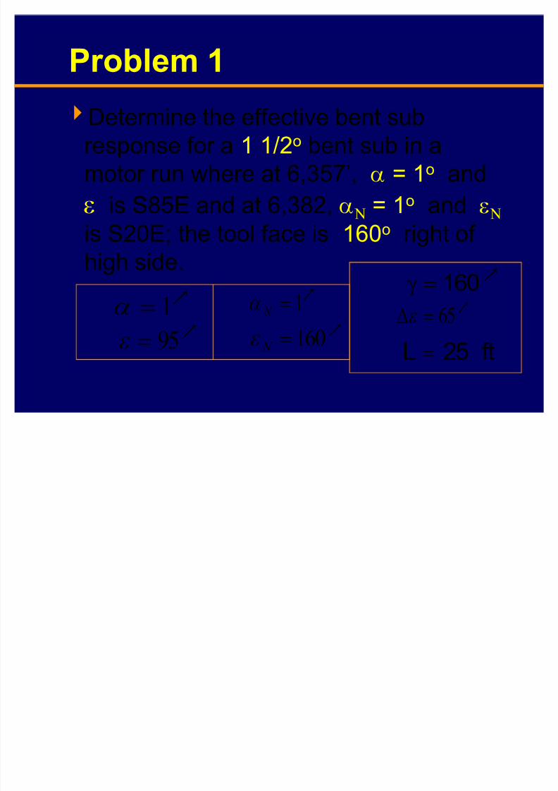
Problem 1
Determine the effective bent sub
response for a 1 1/2o bent sub in a
motor run where at 6,357¶, E = 1o and
I is S85E and at 6,382, E2 = 1o and I2is S20E; the tool face is 160o right of
high side.
Q95!I
Q160!
N I
Q65!(I
ft25L !
Q160
!KQ1!E
Q1! N
E

8/8/2019 406 Lesson 21
http://slidepdf.com/reader/full/406-lesson-21 6/44
Solution to Problem 1
Calculate F from Eq. 8.53:
Dogleg severity:
? AEEEE( F coscossinsincoscos
NN
1
? AQQQQQ 1cos1cos1sin1sin65coscos 1 !
Q07.1999824.0cos
1 !!
ft10028.4
25
10007.1
L
i o!! F!H

8/8/2019 406 Lesson 21
http://slidepdf.com/reader/full/406-lesson-21 7/44
Solution to Problem 1 - cont¶d
If the mud motor length is 25 ft from the
bit face to the bent sub, the maximum
angle change that could be reached if
there are no restrictions is:
The lower rate of build implies that theformation resisted the maximum rate of
build by a factor of:
ft255 o
!!H
72.00.6
3.4!
Q
Q
An efficiency factor?
8/8/2019 406 Lesson 21
http://slidepdf.com/reader/full/406-lesson-21 8/44
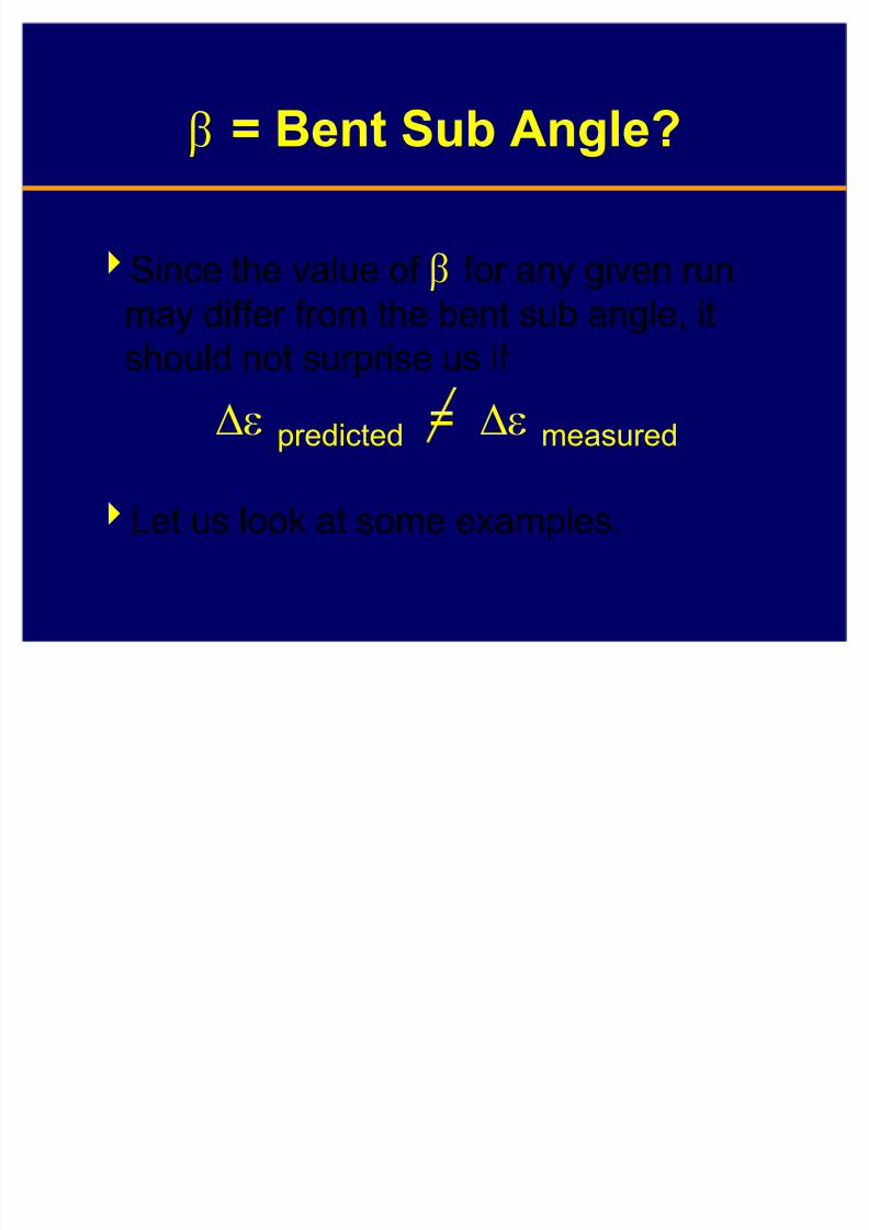
F=
Bent Sub Angle?
Since the value of F for any given run
may differ from the bent sub angle, itshould not surprise us if
(I predicted = (I measured
Let us look at some examples.
8/8/2019 406 Lesson 21
http://slidepdf.com/reader/full/406-lesson-21 9/44
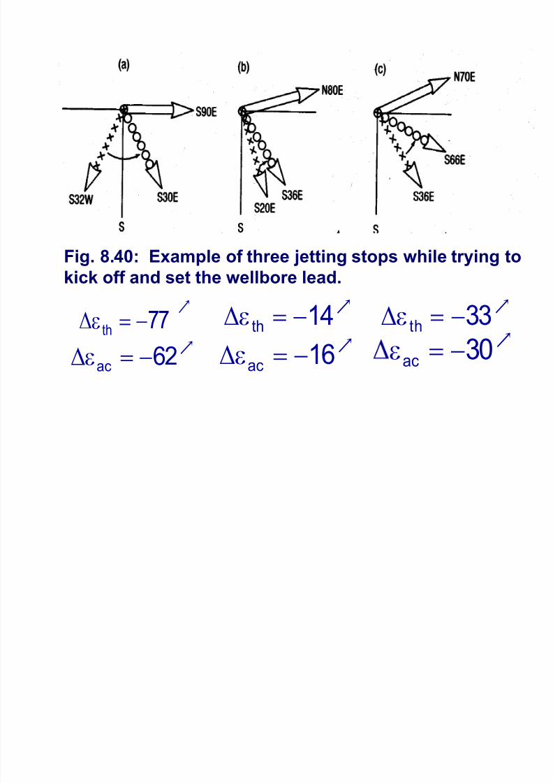
Q
77th
!I(
Q62
ac!I(
Q30
ac!I
Q14
th!I(
Q16
ac!I(
Q33
th!I(
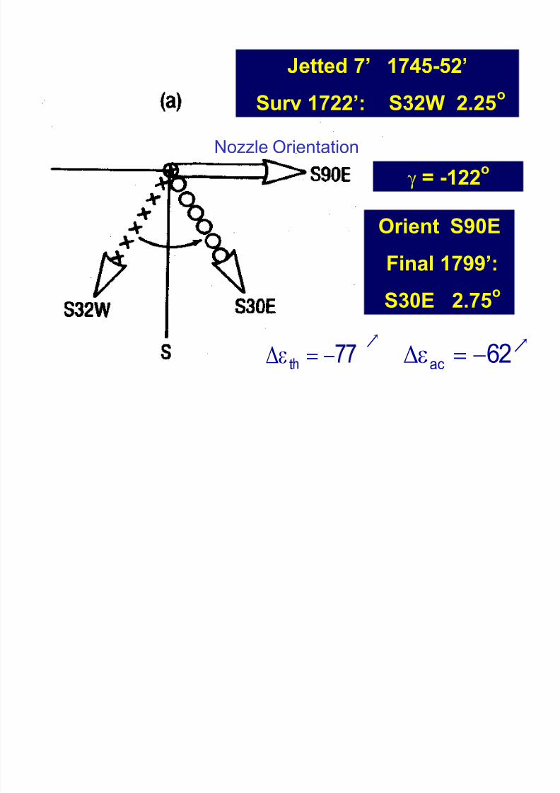
Fig. 8.40: Example of three jetting stops while trying to
kick off and set the wellbore lead.
8/8/2019 406 Lesson 21
http://slidepdf.com/reader/full/406-lesson-21 10/44
Jetted 7¶ 1745-52
Surv 1722¶: S32W 2.25o
Orient S90E
Final 1799¶:
S30E 2.75o
K = -122o
Nozzle Orientation
Q
t !I(Q
62ac
!I(
8/8/2019 406 Lesson 21
http://slidepdf.com/reader/full/406-lesson-21 11/44
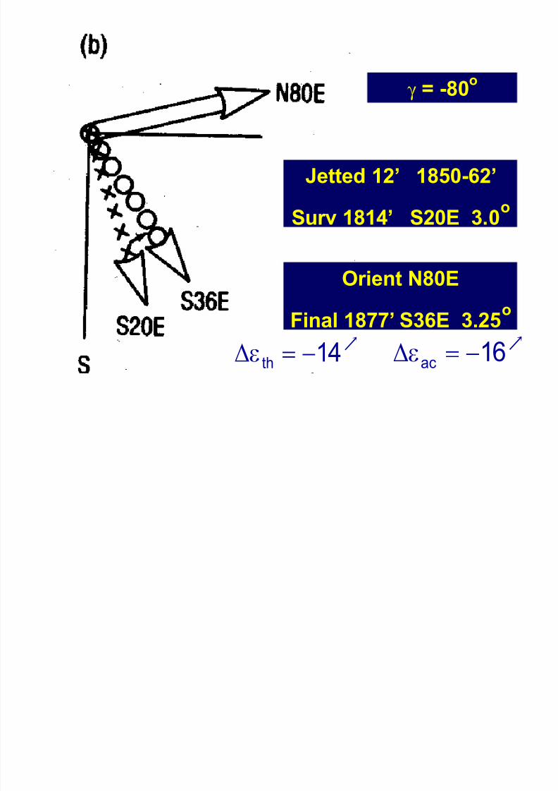
Jetted 12¶ 1850-62
Surv 1814¶ S20E 3.0o
Orient N80E
Final 1877¶ S36E 3.25o
K=
-80
o
Q14
th!I(
Q16
ac!I(
8/8/2019 406 Lesson 21
http://slidepdf.com/reader/full/406-lesson-21 12/44
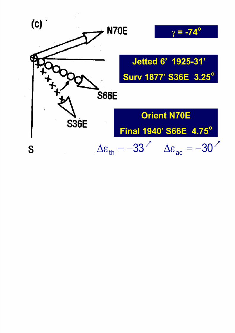
Jetted 6¶ 1925-31
Surv 1877¶ S36E 3.25o
Orient N70E
Final 1940¶ S66E 4.75o
K = -74o
Q30
ac!I(
Q33
th!I(
8/8/2019 406 Lesson 21
http://slidepdf.com/reader/full/406-lesson-21 13/44
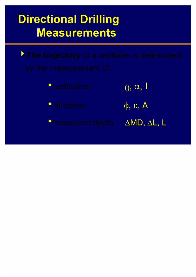
Directional Drilling
Measurements
The trajectory of a wellbore is determined
by the measurement of:
inclination UE I
direction JI A
measured depth (MD, (L, L

8/8/2019 406 Lesson 21
http://slidepdf.com/reader/full/406-lesson-21 14/44
Directional Drilling
Measurements - cont¶d
A tool-face measurement is required to
orient:
a whipstock
the large nozzle on a jetting bit
a bent sub or bent housing
8/8/2019 406 Lesson 21
http://slidepdf.com/reader/full/406-lesson-21 15/44
Directional Drilling
Measurements - cont¶d
Tools availablesingle-shot magnetic or gyroscopic
multi-shot magnetic or gyroscopic
magnetometers, accelerometers,MWD tools
8/8/2019 406 Lesson 21
http://slidepdf.com/reader/full/406-lesson-21 16/44
Magnetic Single-Shot Instrument
Records
± inclination
±direction ± tool face position
on sensitized paper or photographic film
Inclination may be determined by ±a float on a liquid
±a pendulum
8/8/2019 406 Lesson 21
http://slidepdf.com/reader/full/406-lesson-21 17/44
8/8/2019 406 Lesson 21
http://slidepdf.com/reader/full/406-lesson-21 18/44
Magnetic Single-Shot Instrument
Single-shot instruments are used:
± to monitor progress of directional-control well.
± to monitor progress of deviation-control
well. ± to help orient tool face for trajectory
change.
8/8/2019 406 Lesson 21
http://slidepdf.com/reader/full/406-lesson-21 19/44
Magnetic Single-Shot
Instrument - cont¶d
Procedure:
± load film into instrument ±activate timer (activate stopwatch)
±make up the tool
±drop the tool ± retrieve tool (wireline or drillpipe)

8/8/2019 406 Lesson 21
http://slidepdf.com/reader/full/406-lesson-21 20/44
8/8/2019 406 Lesson 21
http://slidepdf.com/reader/full/406-lesson-21 21/44
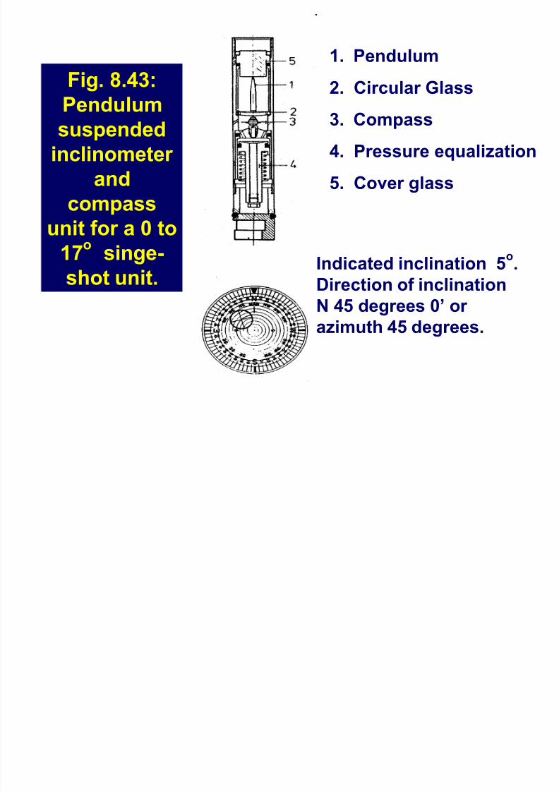
Fig. 8.43:
Pendulumsuspended
inclinometer
and
compassunit for a 0 to
17oo singe-
shot unit.
1. Pendulum
2. Circular Glass
3. Compass
4. Pressure equalization
5. Cover glass
Indicated inclination 5o.
Direction of inclination
N 45 degrees 0¶ or
azimuth 45 degrees.
8/8/2019 406 Lesson 21
http://slidepdf.com/reader/full/406-lesson-21 22/44
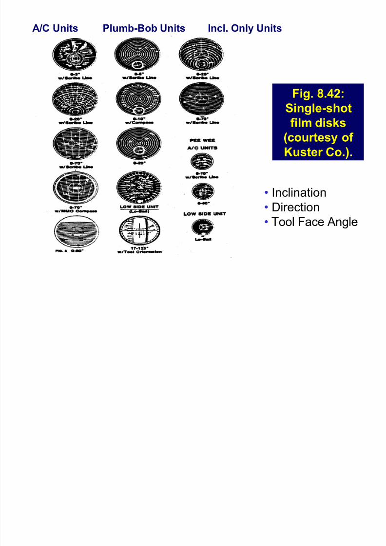
Fig. 8.42:
Single-shot
film disks
(courtesy of Kuster Co.).
A/C Units Plumb-Bob Units Incl. Only Units
Inclination
Direction Tool Face Angle
8/8/2019 406 Lesson 21
http://slidepdf.com/reader/full/406-lesson-21 23/44
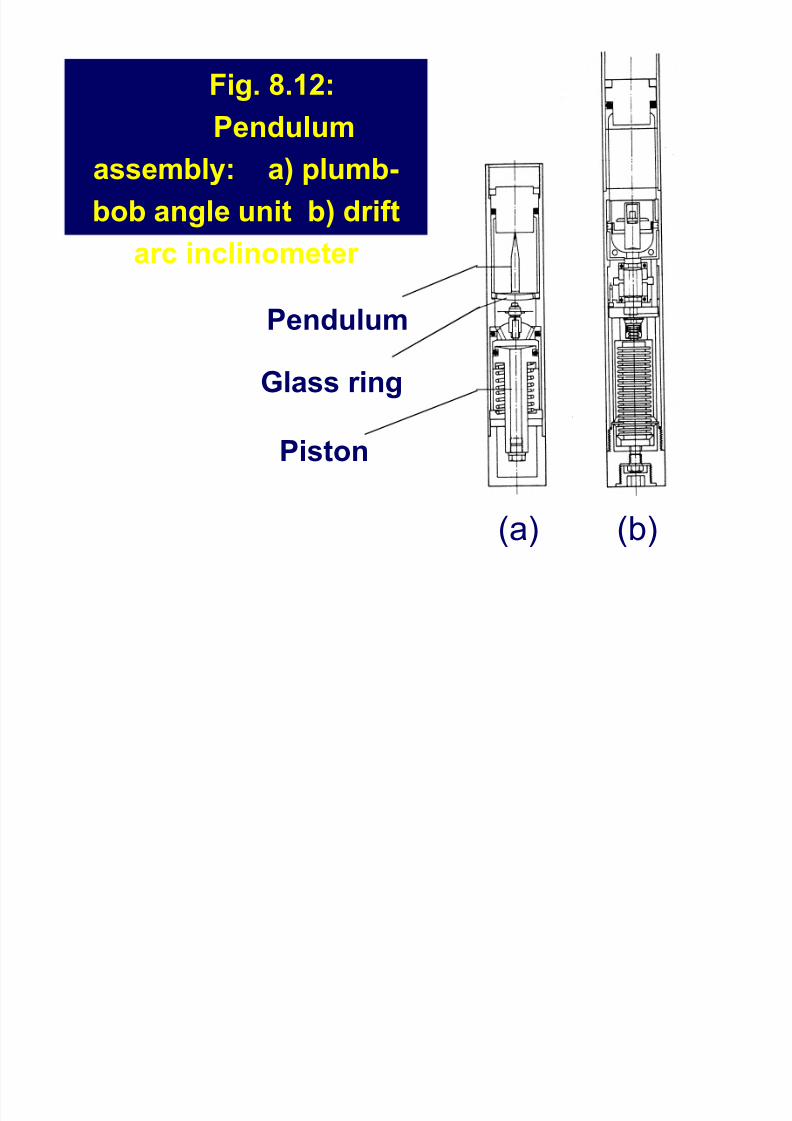
Fig. 8.12:
Pendulumassembly: a) plumb-
bob angle unit b) drift
arc inclinometer
Pendulum
Glass ring
Piston
(a) (b)
8/8/2019 406 Lesson 21
http://slidepdf.com/reader/full/406-lesson-21 24/44
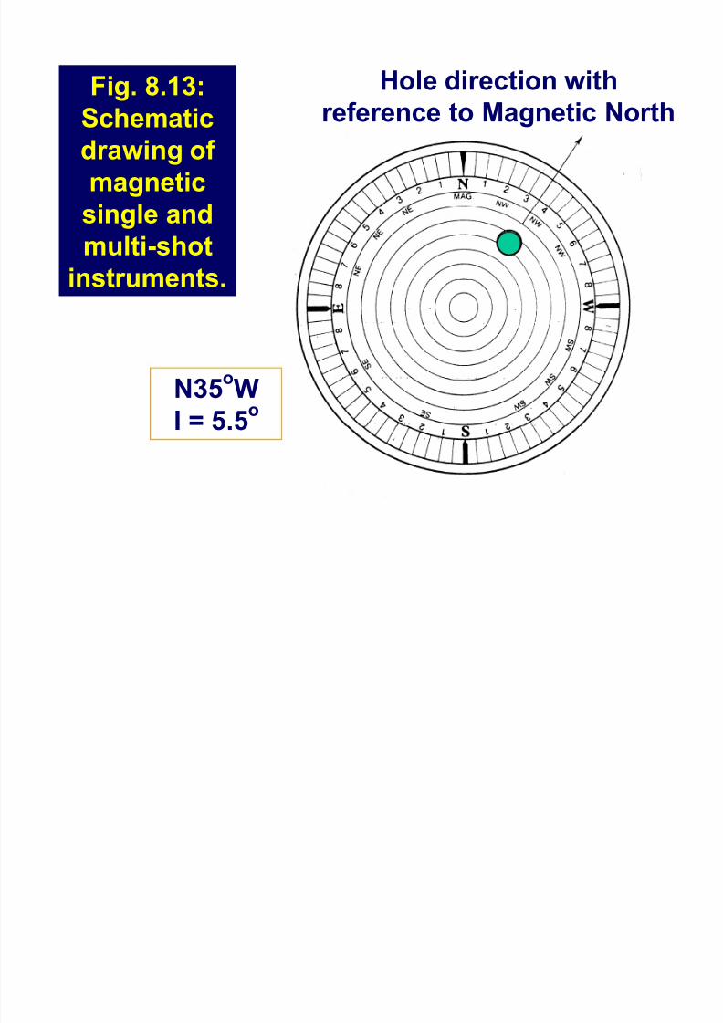
Fig. 8.13:
Schematicdrawing of
magnetic
single and
multi-shotinstruments.
Hole direction with
reference to Magnetic North
N35oWI = 5.5
o
8/8/2019 406 Lesson 21
http://slidepdf.com/reader/full/406-lesson-21 25/44
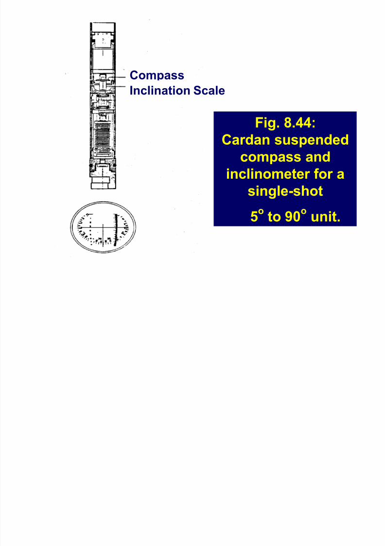
Fig. 8.44:
Cardan suspendedcompass and
inclinometer for a
single-shot
5o
to 90o
unit.
Compass
Inclination Scale
8/8/2019 406 Lesson 21
http://slidepdf.com/reader/full/406-lesson-21 26/44
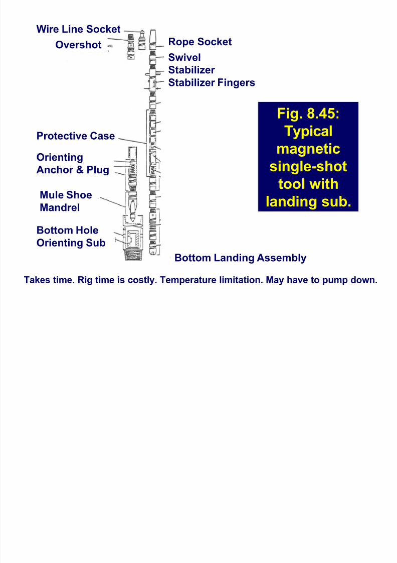
Fig. 8.45:
Typical
magnetic
single-shot
tool with
landing sub.
Rope Socket
Swivel
Stabilizer Stabilizer Fingers
Wire Line Socket
Overshot
Bottom Landing Assembly
Protective Case
Mule Shoe
Mandrel
Bottom Hole
Orienting Sub
Orienting
Anchor & Plug
Takes time. Rig time is costly. Temperature limitation. May have to pump down.
8/8/2019 406 Lesson 21
http://slidepdf.com/reader/full/406-lesson-21 27/44
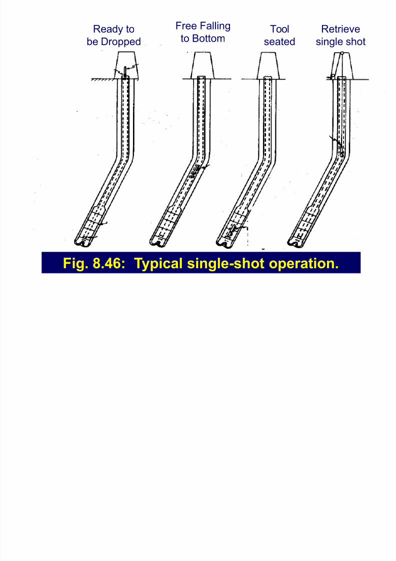
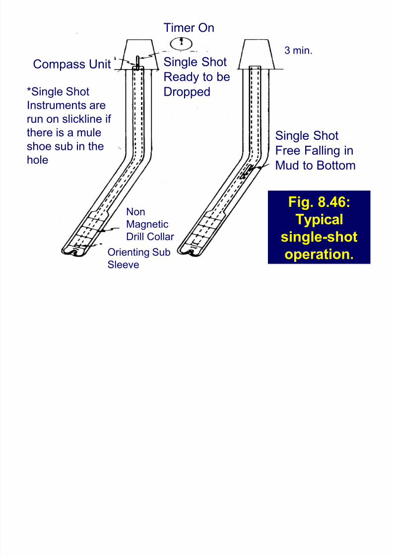
Fig. 8.46: Typical single-shot operation.
Free Falling
to BottomTool
seated
Ready to
be Dropped
Retrieve
single shot
8/8/2019 406 Lesson 21
http://slidepdf.com/reader/full/406-lesson-21 28/44
Fig. 8.46:Typical
single-shot
operation.
CompassU
nit
3 min.
Single ShotFree Falling in
Mud to Bottom
Non
Magnetic
Drill Collar
Orienting Sub
Sleeve
*Single Shot
Instruments are
run on slickline if
there is a mule
shoe sub in the
hole
Single Shot
Ready to be
Dropped
Timer On
8/8/2019 406 Lesson 21
http://slidepdf.com/reader/full/406-lesson-21 29/44
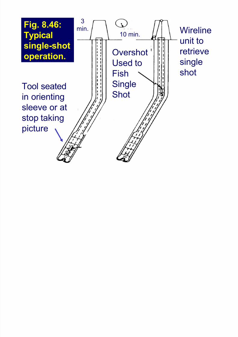
Fig. 8.46:
Typical
single-shotoperation.
3
min.
Overshot
Used to
Fish
SingleShot
Tool seatedin orienting
sleeve or at
stop taking
picture
Wireline
unit toretrieve
single
shot
10 min.
8/8/2019 406 Lesson 21
http://slidepdf.com/reader/full/406-lesson-21 30/44
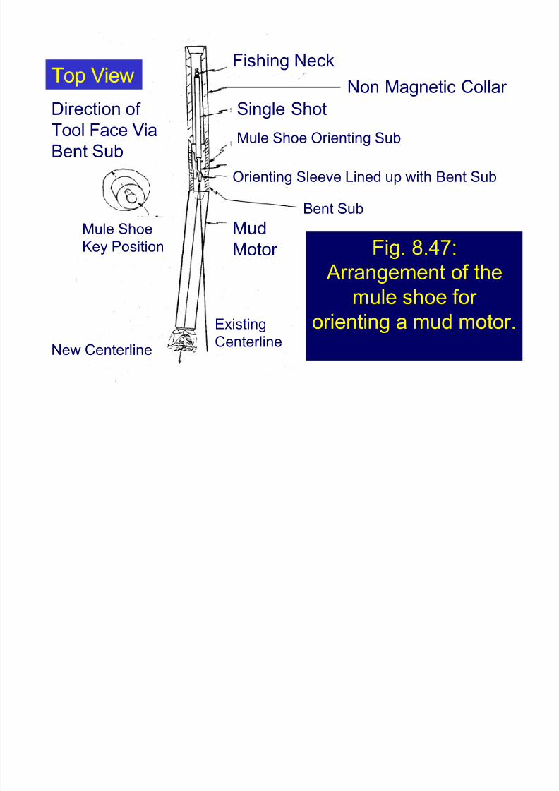
Fig. 8.47:
Arrangement of the
mule shoe for orienting a mud motor.
Fishing Neck
Non Magnetic Collar
Single Shot
Mud
Motor
Top View
Existing
CenterlineNew Centerline
Bent Sub
Mule Shoe
Key Position
Mule Shoe Orienting Sub
Orienting Sleeve Lined up with Bent Sub
Direction of
Tool Face Via
Bent Sub
8/8/2019 406 Lesson 21
http://slidepdf.com/reader/full/406-lesson-21 31/44
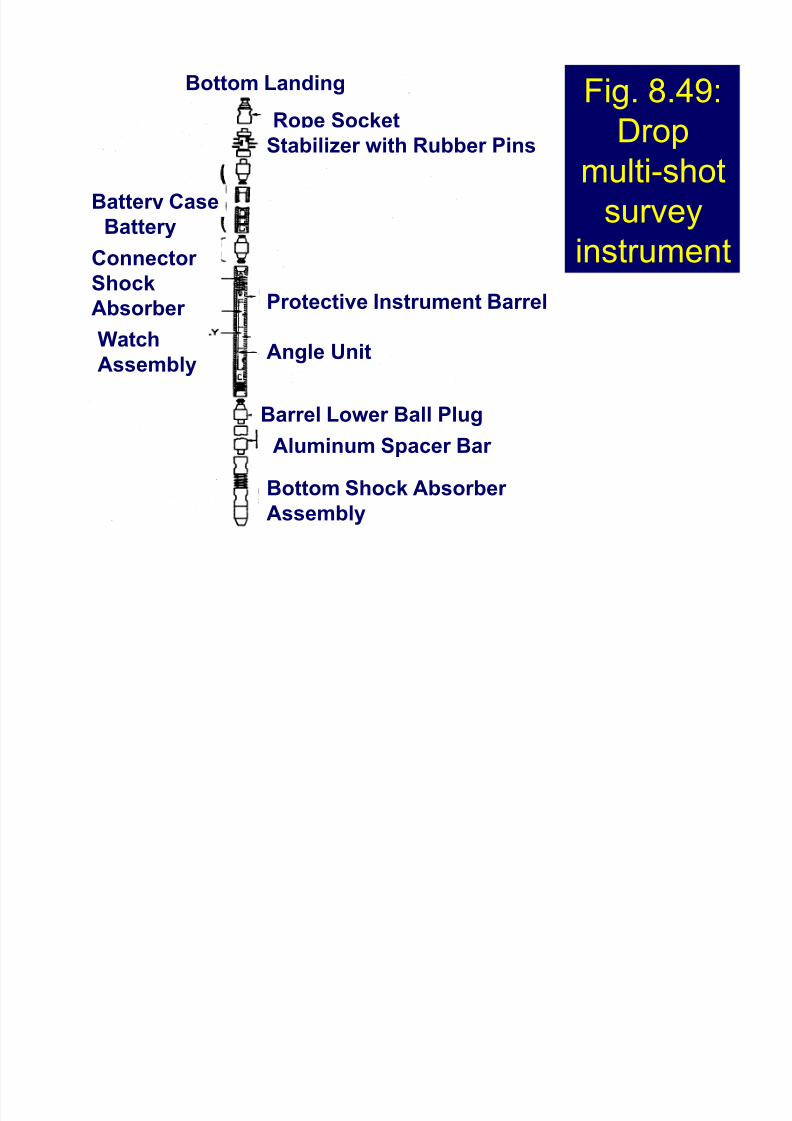
Magnetic Multishot Instruments
Are capable of taking numerous survey
records in one run.
May be dropped down the drillpipe or run
on wireline in open hole.
The unit contains a watch that is spring
wound and uses the power of the spring
to operate a timer cam.
8/8/2019 406 Lesson 21
http://slidepdf.com/reader/full/406-lesson-21 32/44
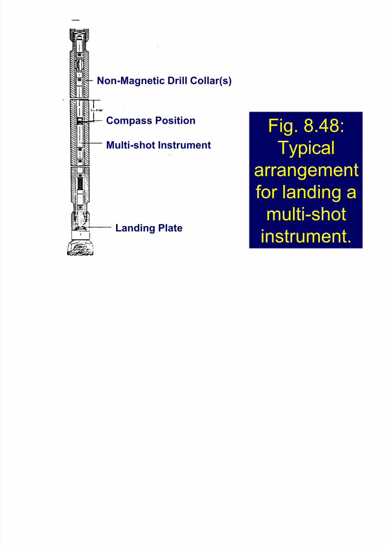
Fig. 8.48:
Typical
arrangement
for landing a
multi-shot
instrument.
Non-Magnetic Drill Collar(s)
Compass Position
Multi-shot Instrument
Landing Plate
8/8/2019 406 Lesson 21
http://slidepdf.com/reader/full/406-lesson-21 33/44
8/8/2019 406 Lesson 21
http://slidepdf.com/reader/full/406-lesson-21 34/44
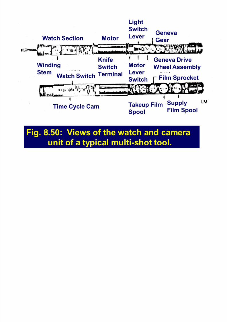
Fig. 8.50: Views of the watch and camera
unit of a typical multi-shot tool.
Watch Section Motor
Light
Switch
Lever Geneva
Gear
Winding
Stem
Time Cycle Cam
Watch Switch
Supply
Film SpoolTakeup Film
Spool
F
ilm Sprocket
Motor
Lever
Switch
Geneva Drive
Wheel Assembly
Knife
Switch
Terminal
8/8/2019 406 Lesson 21
http://slidepdf.com/reader/full/406-lesson-21 35/44
Magnetic Multishot - cont¶d
The multishot tool is usually dropped down
the drillpipe and landed in the nonmagneticdrill collar.
During the trip out, a survey is taken every
90 ft, i.e. every stand.
8/8/2019 406 Lesson 21
http://slidepdf.com/reader/full/406-lesson-21 36/44
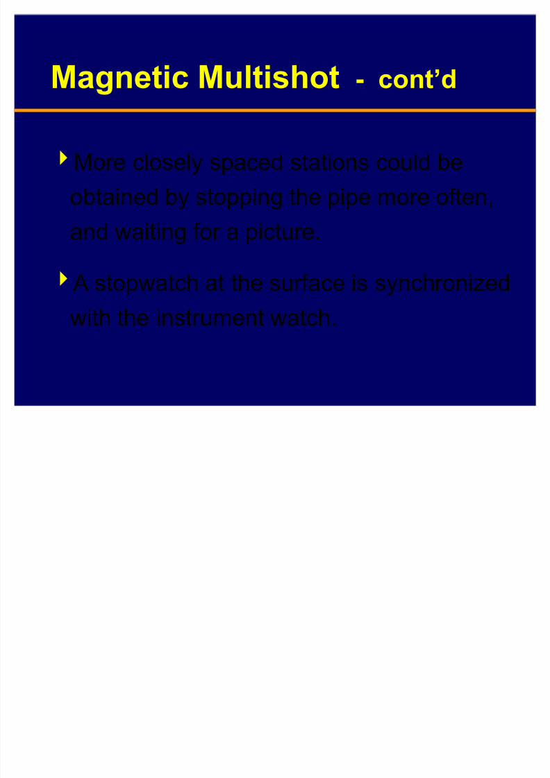
Magnetic Multishot - cont¶d
More closely spaced stations could be
obtained by stopping the pipe more often,and waiting for a picture.
A stopwatch at the surface is synchronizedwith the instrument watch.
8/8/2019 406 Lesson 21
http://slidepdf.com/reader/full/406-lesson-21 37/44
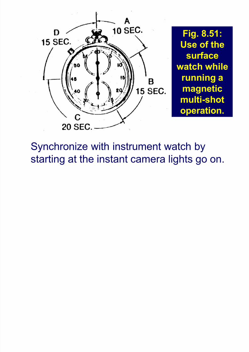
Synchronize with instrument watch by
starting at the instant camera lights go on.
Fig. 8.51:
Use of thesurface
watch while
running a
magneticmulti-shot
operation.
8/8/2019 406 Lesson 21
http://slidepdf.com/reader/full/406-lesson-21 38/44
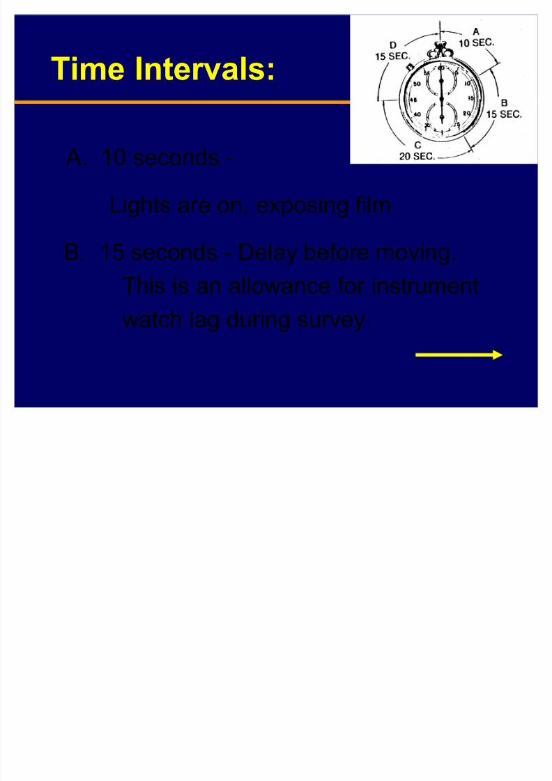
A. 10 seconds -
Lights are on, exposing film
B. 15 seconds - Delay before moving.
This is an allowance for instrumentwatch lag during survey.
Time Intervals:
8/8/2019 406 Lesson 21
http://slidepdf.com/reader/full/406-lesson-21 39/44
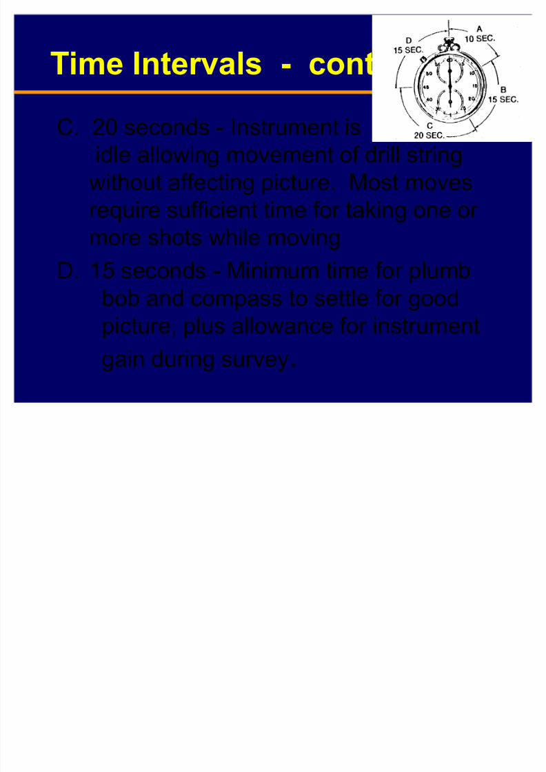
C. 20 seconds - Instrument is
idle allowing movement of drill string
without affecting picture. Most movesrequire sufficient time for taking one or
more shots while moving
D. 15 seconds - Minimum time for plumb
bob and compass to settle for good
picture, plus allowance for instrument
gain during survey.
Time Intervals - cont¶d
8/8/2019 406 Lesson 21
http://slidepdf.com/reader/full/406-lesson-21 40/44
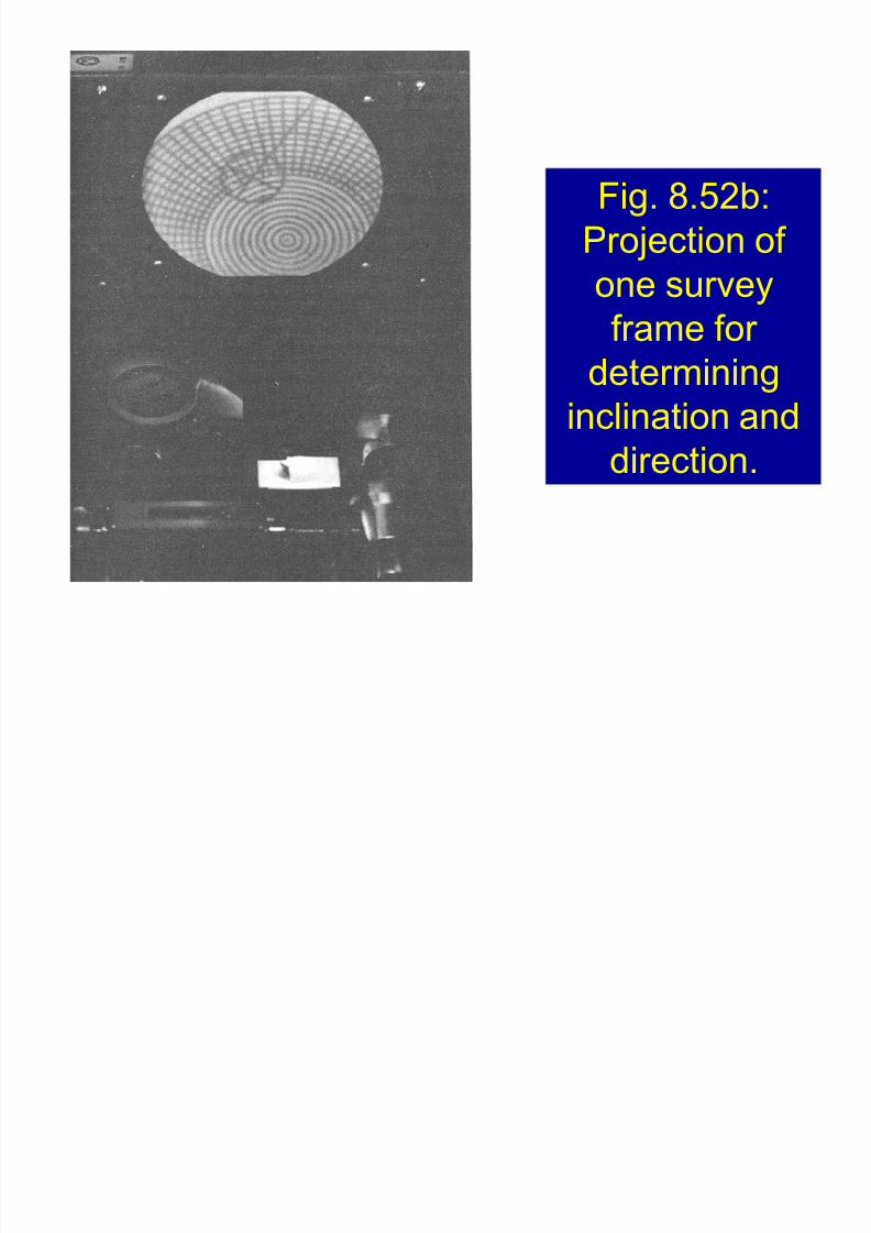
Fig. 8.52b:
Projection of
one survey
frame for
determining
inclination and
direction.
8/8/2019 406 Lesson 21
http://slidepdf.com/reader/full/406-lesson-21 41/44
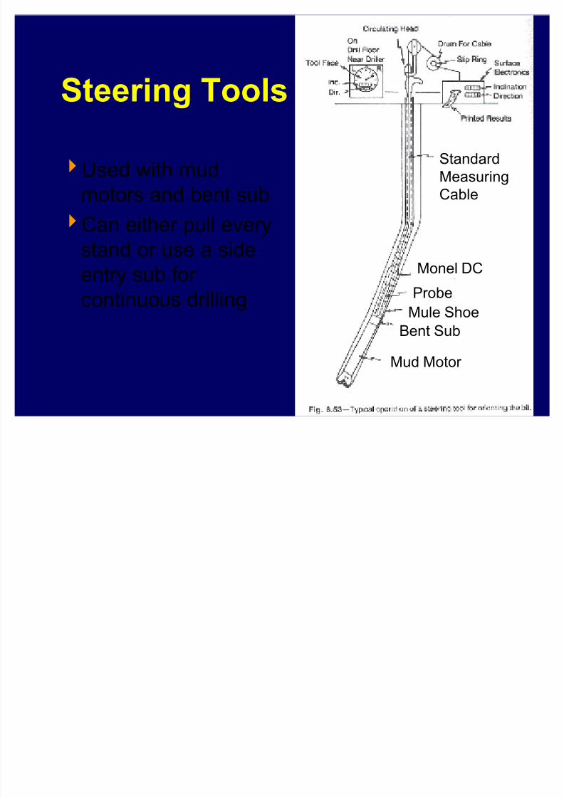
Steering Tools
Used with mud
motors and bent subCan either pull every
stand or use a side
entry sub for
continuous drilling
Mud Motor
Bent Sub
Mule Shoe
Monel DC
Probe
Standard
Measuring
Cable
8/8/2019 406 Lesson 21
http://slidepdf.com/reader/full/406-lesson-21 42/44
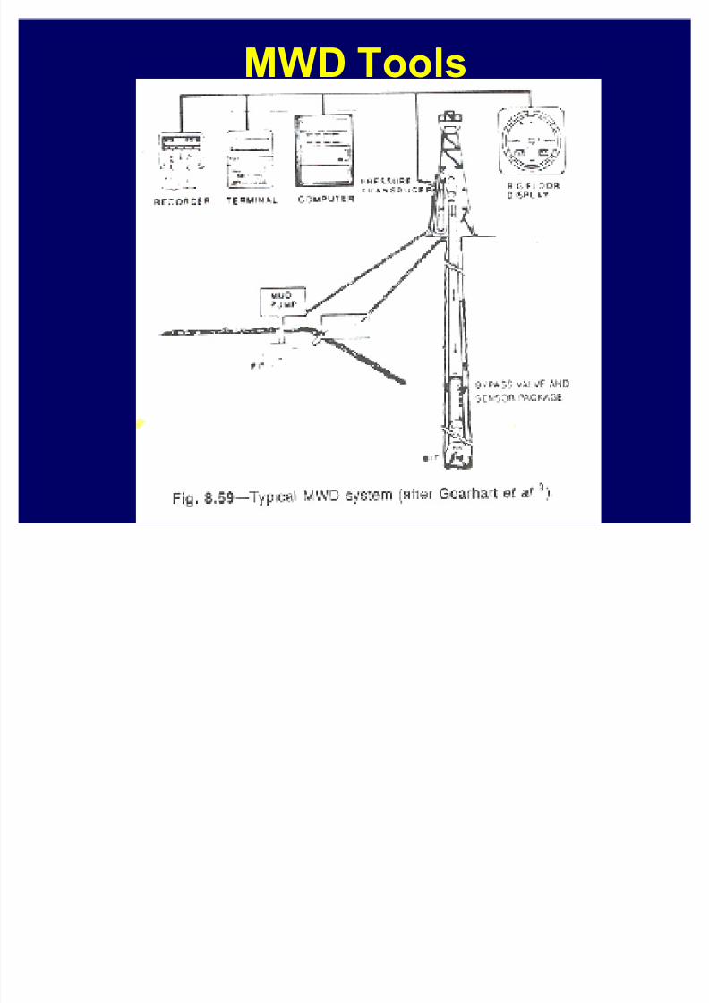
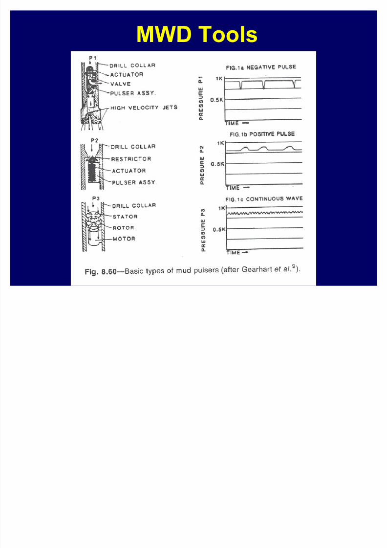
MWD Tools
8/8/2019 406 Lesson 21
http://slidepdf.com/reader/full/406-lesson-21 43/44
MWD Tools

8/8/2019 406 Lesson 21
http://slidepdf.com/reader/full/406-lesson-21 44/44
Gyroscopic ToolsNon-magnetic drill
collars used to prevent
magnetic interferencefrom drillstring
Gyros used if magnetic
interference is from
non drillstring source