Embed Size (px)
Citation preview

User Manual
Operation and Installation Guidelines
V. 1.02 / Sept 2012 / Doc 40261
BC6000 SNMP Alarm and Control Module
For Network management
BC6000 User Guide
Brodersen A/S, Islevdalvej 187, DK-2610 Roedovre, Denmark , Tel: +45 45 35 26 27, Fax: +45 45 35 26 29, Email: [email protected] 2
Table of Contents
1. Introduction ........................................................................................................................................ 4
2. BC6000 SNMP Agent Alarm and Control functions ................................................................................. 4
3. Technical details .................................................................................................................................. 6
3.1 Basic features .......................................................................................................................................... 6
3.2 Interfaces ................................................................................................................................................. 6
3.3 I/O for alarms and control ....................................................................................................................... 7
4. Configuration and Communication........................................................................................................ 9
4.1 Basic configuration .................................................................................................................................. 9
4.1.1 Settings overview .......................................................................................................................... 9
4.1.2 Network Settings ......................................................................................................................... 10
4.1.3 Time Settings ............................................................................................................................... 11
4.1.4 Change password .................................................................................................................. 11
4.1.5 Basic SNMP settings .................................................................................................................... 12
4.1.6 MIB II Settings ............................................................................................................................. 12
4.1.7 Communication and Trap receivers ............................................................................................ 13
4.1.8 Permitted Managers ................................................................................................................... 13
4.2 SNMP I/O Alarm and Control Configuration.......................................................................................... 14
4.2.1 Configuration of SNMP I/O alarms and control functions........................................................... 14
4.2.2 I/O Addressing ............................................................................................................................. 25
5 OID Structure and MIB ........................................................................................................................ 26
5.1 Introduction ........................................................................................................................................... 26
5.2 MIB and OID – general information ...................................................................................................... 26
5.3 MIB and OID - overview......................................................................................................................... 27
6. Installation and Wiring ....................................................................................................................... 31
6.1 Mounting ............................................................................................................................................... 31
6.2 Power supply ......................................................................................................................................... 31
6.3 Digital inputs .......................................................................................................................................... 31
6.4 Relay outputs ......................................................................................................................................... 32
6.5 Analogue inputs ..................................................................................................................................... 32

BC6000 User Guide
Brodersen A/S, Islevdalvej 187, DK-2610 Roedovre, Denmark , Tel: +45 45 35 26 27, Fax: +45 45 35 26 29, Email: [email protected] 3
6.6 Analogue outputs .................................................................................................................................. 32
6.7 I/O Expansion modules .......................................................................................................................... 33
7. Technical Data ................................................................................................................................... 34
Appendix 1 – I/O Addressing .................................................................................................................. 35

BC6000 User Guide
Brodersen A/S, Islevdalvej 187, DK-2610 Roedovre, Denmark , Tel: +45 45 35 26 27, Fax: +45 45 35 26 29, Email: [email protected] 4
1. Introduction
SNMP (Simple Network Management Protocol) is the common language of network monitoring and used for
telecommunications, facility and asset monitoring applications. The protocol allows IT Network Administration staff
to easily monitor the BC6000 Alarm and Control modules in big networks. An even more powerful feature of the
protocol is to use the BC6000 to monitor the network by sending/receiving SNMP network alarms. This is a feature
often used by network facility managers.
The Brodersen BC6000 SNMP Alarm module is a simple to use configurable device for SNMP Trap Alarm and Control.
The BC6000 is based on the Brodersen RTU32 platform with software dedicated for SNMP Alarm, monitoring and
control processing.
It is designed for alarm, monitoring and control applications on sites in Data Communication Network (DCN), Server
rooms etc.
The module provides you with all necessary functions for converting, communicating and reporting alarms in
network communication systems to an SNMP Management System. The unit can e.g. be used for UPS and Generator
System alarms, air-condition system alarms, voltage level alarms, direct environmental alarming like temperature,
relative humidity, water etc. Up to several hundreds alarms can be managed.
2. BC6000 SNMP Agent Alarm and Control functions
The BC6000 SNMP works as a general SNMP Agent and includes basic SNMP Agent functions. The MS WinCE
operating system provides network information such as general network device parameters, statistical information
etc.
The BC6000 SNMP Agent complies in general with the SNMPv2C standard.
The SNMP Agent is BC6000 is designed for fully dynamic management via the SNMP Management software. Settings
in tables can dynamically be edited/changed using your SNMP Manager. It means that once you have setup the basic
network and SNMP settings (like IP addresses, Community, Trap receivers and Permitted Managers), all settings for
trap handling i.e. alarm messages, physical I/O link etc. can be configured directly via the SNMP manager as an
alternative to using the configuration web pages in the BC6000.
C
Local bus connection
Additional expansionmodules
BC6000 User Guide
Brodersen A/S, Islevdalvej 187, DK-2610 Roedovre, Denmark , Tel: +45 45 35 26 27, Fax: +45 45 35 26 29, Email: [email protected] 5
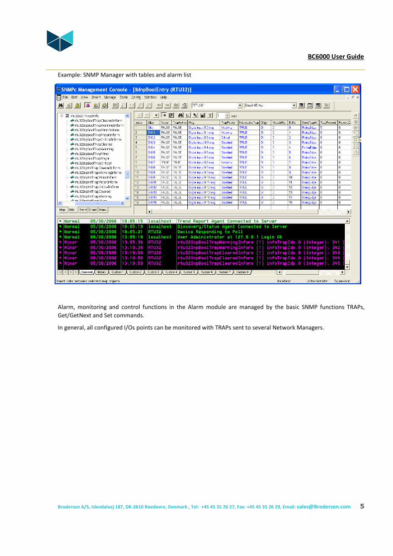
Example: SNMP Manager with tables and alarm list
Alarm, monitoring and control functions in the Alarm module are managed by the basic SNMP functions TRAPs,
Get/GetNext and Set commands.
In general, all configured I/Os points can be monitored with TRAPs sent to several Network Managers.

BC6000 User Guide
Brodersen A/S, Islevdalvej 187, DK-2610 Roedovre, Denmark , Tel: +45 45 35 26 27, Fax: +45 45 35 26 29, Email: [email protected] 6
Example detailed of table for monitoring and editing BC6000 configuration in a SNMP Management System.
Analogue I/Os are equipped with 4 alarm levels. Alarms can be configured according to your requirements, using
multiple alarm levels, prioritizing alarms etc
Any SNMP I/O can be polled for status with Get/GetNext, and all control outputs can be managed with the Set
function. I/Os are easy to manage as tables in SNMP Management Systems.
3. Technical details
3.1 Basic features
As the BC6000 SNMP is running MS WinCE, it includes a basic SNMP Master Agent plus a basic Extension Agent. The
basic Extension Agent is part of the Microsoft environment for reporting network information etc. The SNMP Agent
complies with the SNMPv2C standard.
The id for the BC6000 SNMP in managed networks is enterprise no 24122 (branch name/number for Brodersen A/S).
The basic BC6000 SNMP includes a fixed number of I/Os and additional inputs/output can be added via I/O Expansion
modules.
3.2 Interfaces
The BC6000 provide a number of interfaces. The primary interfaces for use are:
• Power supply input: 24-48VDC (optional 115-230VAC/DC)
• Network connections LAN1 and LAN2: 10/100MBit Fast Ethernet compatible
• LocalBus Interface: RJ45 for connection I/O Expansion modules
• 12VDC supply output for alarm inputs.

BC6000 User Guide
Brodersen A/S, Islevdalvej 187, DK-2610 Roedovre, Denmark , Tel: +45 45 35 26 27, Fax: +45 45 35 26 29, Email: [email protected] 7
3.3 I/O for alarms and control
Basic I/O configuration
A basic module features 16 digital bipolar inputs, 4 relay outputs, 4 analogue inputs and 2 analogue outputs. The
inputs are designed for 24-60VDC with positive or negative common.
Expansion I/O configuration
I/O expansion is provided by adding I/O expansion modules. They are available with;
• 32 bipolar digital inputs 24-60VDC
• 16 relay outputs
• 8 analogue inputs (Pt100, 0-10VDC or 4-20mA)
• 4 analogue outputs as 0-10V or 4-20mA.
The I/O expansion modules are simply added to the basic module with a small bus cable that includes internal
communication and power supply – no additional wiring needed except for the I/Os.
C
BC_SNMP
2 analogue outputs 16 digital inputs
4 relay outputs 4 analogue inputs

BC6000 User Guide
Brodersen A/S, Islevdalvej 187, DK-2610 Roedovre, Denmark , Tel: +45 45 35 26 27, Fax: +45 45 35 26 29, Email: [email protected] 8
If your configuration of I/O Expansion modules exceed consumption of more than 900mA an additional power supply
(type UCS-53 or UCS-54) must be added. See I/O Expansion selection guide for details.
The BC6000 support setup of a maximum I/O configuration of;
• 200 bipolar digital inputs 24-60VDC
• 200 relay outputs
• 200 analogue inputs
• 200 analogue outputs
C
BC_SNMP
16 digital inputs 8 analogue inputs
16 digital inputs
UCX-32DI.. UCX-08AI..
2 analogue outputs 16 digital inputs
4 relay outputs 4 analogue inputs
C 0 1 2 3 4 5 6 7 C In In
C 8 9 10 11 12 13 14 15 C
C D
0 1 2 3 4 5 6 7
A
8 9 10 11 12 13 14 15
B
UCL-32 DI.D1
System I/O
0 1 2 3 4 5 6 7 8 9 10 11 12 13 14 15
C 0 1 2 3 4 5 6 7 C In In
C 8 9 10 11 12 13 14 15 C

BC6000 User Guide
Brodersen A/S, Islevdalvej 187, DK-2610 Roedovre, Denmark , Tel: +45 45 35 26 27, Fax: +45 45 35 26 29, Email: [email protected] 9
4. Configuration and Communication
4.1 Basic configuration
All configurations of the BC6000 SNMP alarm and control modules are done via the built-in web pages. As default the
LAN1 is assigned with IP address 192.168.0.1 and LAN2 is set to DHCP.
After having set up your password, the main configuration page of the RTU32 will appear in your browser. Next time
you connect to the web pages you will be asked for username and password authentication to get access.
NOTE: That the basic configuration for the BC6000 ONLY includes Network Settings and
SNMP Settings – all other setting may be ignored.
4.1.1 Settings overview
The first page that appears when you enter the RTU32 Web pages is the “Settings Overview” page.
On this page you will get an overview of the network settings and version of the primary system files. If you are
contacting your support office or distributor, you will be asked for the software version numbers.
IMPORTANT NOTE: The local IP will report 0.0.0.0 if the LAN port is not active (not connected/no connection).
Check the network settings page for getting the last saved network settings.

BC6000 User Guide
Brodersen A/S, Islevdalvej 187, DK-2610 Roedovre, Denmark , Tel: +45 45 35 26 27, Fax: +45 45 35 26 29, Email: [email protected]
10
4.1.2 Network Settings
On the “Network Setting” page you can change the LAN1 and LAN2 settings to fit your local network. You must assign
fixed IP addresses to gain access to the BC6000 SNMP with your browser in your LAN network.
After entering the new network settings, select “Apply” to save the settings. Note that the new settings will NOT be
activated before you reboot the BC6000 SNMP. Use the Boot function on the menu at the left side of the page.
The BC6000 SNMP unit can also be assigned a unique device name (Station name), which is entered in top of the
“Network Settings” page.

BC6000 User Guide
Brodersen A/S, Islevdalvej 187, DK-2610 Roedovre, Denmark , Tel: +45 45 35 26 27, Fax: +45 45 35 26 29, Email: [email protected]
11
4.1.3 Time Settings
The “Time Settings” web page is used for setting the BC6000 SNMP real-time clock. You can choose to enter the time
manually or set the time from a network time server using SNTP. If you use SNTP you have to enter the domain name
(like www.example.com) or IP address of the time server.
4.1.4 Change password
You can change the login password for web server access, FTP etc. The User name is always admin.

BC6000 User Guide
Brodersen A/S, Islevdalvej 187, DK-2610 Roedovre, Denmark , Tel: +45 45 35 26 27, Fax: +45 45 35 26 29, Email: [email protected]
12
4.1.5 Basic SNMP settings
The “SNMP Settings” page covers the basic settings of the SNMP Agent driver in the BC6000 SNMP. It covers both
settings for the basic WinCE Agent Driver which report network parameters and the BC6000 SNMP Alarm Extension
Agent. The basic BC6000 SNMP Agent is handled by the WinCE OS and includes the standard functions for network
data and statistics implemented by Microsoft©.
The configurable parameters for the SNMP Agent Driver are listed in the following sections.
4.1.6 MIB II Settings
MIB II is the basic WinCE SNMP Agent. It is possible to define specific information in the basic agent. The information
covers Contact, Location and Object Id. NOTE: Do not remove the object id unless you have full control over the
SNMP Manager settings.

BC6000 User Guide
Brodersen A/S, Islevdalvej 187, DK-2610 Roedovre, Denmark , Tel: +45 45 35 26 27, Fax: +45 45 35 26 29, Email: [email protected]
13
4.1.7 Communication and Trap receivers
In this configuration area you are able to set-up up to 4 communities with each 4 SNMP Managers’ IP addresses.
Note that the community “public” is default and normally recognised by all SNMP Management software. In addition
each community can be adjusted to different levels of access permissions. Note also that permission is default set to
Read Only. Remember to change this if you will control outputs.
4.1.8 Permitted Managers
You can control access to Get/GetNext request and Set commands by adding Permitted Managers IP addresses. If no
SNMP Managers are entered, all Managers are allowed access.
If you enable the Authentication Trap function, the permitted managers will get a Trap report if unauthorized
requests have been attempted.

BC6000 User Guide
Brodersen A/S, Islevdalvej 187, DK-2610 Roedovre, Denmark , Tel: +45 45 35 26 27, Fax: +45 45 35 26 29, Email: [email protected]
14
4.2 SNMP I/O Alarm and Control Configuration
4.2.1 Configuration of SNMP I/O alarms and control functions
Generic Traps
GenericTraps are generated from the BC6000 SNMP as default and they cannot be configured from the webpages.
These include:
ColdStart: When the Application program is started the BC6000 SNMP sends a ColdStartTrap.
AutenticationFailure: If an unauthorized person tries to log-in to the BC6000 SNMP via e.g. FTP or Webbrowser
and fails, an AuthenticationTrap will report the event and the Trap will include the IP
address of the device causing the event. This is setup on the web pages SNMP general
settings.
SNMP Device settings

BC6000 User Guide
Brodersen A/S, Islevdalvej 187, DK-2610 Roedovre, Denmark , Tel: +45 45 35 26 27, Fax: +45 45 35 26 29, Email: [email protected]
15
SNMP Table Sizes section
You must here define the numbers of Device texts and I/O configuration you want to work with. You may freely
define the number of I/Os with-in the limits shown in brackets.
Device text section
Here you define text strings that describe details of the device. Each text string is defined in SNMP with its own OID.

BC6000 User Guide
Brodersen A/S, Islevdalvej 187, DK-2610 Roedovre, Denmark , Tel: +45 45 35 26 27, Fax: +45 45 35 26 29, Email: [email protected]
16
SNMP DI Settings / Digital (Boolean) Input
SNMP digital (Booleans) inputs are configured on this page. Each digital input in a system configuration is assigned a
number starting from 0 to max 200. If you have only the basic module with 16 digital inputs, you will physically have
SNMP DI 0 to 15. If you have added a 32 digital expansion module you will have SNMP DI 0 to 47. The numbers of
SNMP DI available is according to your settings on the Device Setting page.
The DIs can be monitored with SNMP Get commands. Each DI is defined by an OID id in the MIB file.
The web pages for configuration works like a window you move up and down on a list of entries. The window size
can be adjusted to show more or less numbers of entries in the top and bottom right corner of the configuration
page. And you also here find the buttons for moving the window up and down the list
The parameters for each SNMP DI are configured with:
Name / Description of input: (text)
Description of the actual inputs. It could be UPS main monitor, door alarm etc. Max.30 characters.
Message / Description of alarm: (text)
Description of the alarm event, like UPS failure, door open alarm etc. Max.255 characters.

BC6000 User Guide
Brodersen A/S, Islevdalvej 187, DK-2610 Roedovre, Denmark , Tel: +45 45 35 26 27, Fax: +45 45 35 26 29, Email: [email protected]
17
I/O Address
See the section for I/O addressing.
Trap Priority
Enables and define Trap priority. There are 5 possibilities;
Disabled (1) – disable Trap for this DI
Warning (2) – DI will send warning Trap
Minor (3) – DI will send minor Trap
Major (4) – DI will send major Trap
Critical (5) – DI will send critical Trap
Send Trap alarm at / Send Trap conditions
The condition for sending Trap – send trap on DI rising edge (OFF to ON) or DI falling edge (ON to OFF).
Trap Type
The Trap can be select if it should be as informative or none–informative type. If informative the Trap contains all
user variables, descriptions and texts.
If none-informative Trap it contain only value and priority – and readable ASCII are not transmitted.
Resend Interval (min)
Define the resend interval in minutes. If set to 0 the Trap is only send once.
Bounce Delay (100 msec)
Defines how many milliseconds the input change should be active before the alarm Trap is sent.

BC6000 User Guide
Brodersen A/S, Islevdalvej 187, DK-2610 Roedovre, Denmark , Tel: +45 45 35 26 27, Fax: +45 45 35 26 29, Email: [email protected]
18
SNMP DO Settings / Digital (Boolean) outputs
SNMP digital (Booleans) outputs are configured on this page. Each digital output in a system configuration is assigned
a number starting from 0 to max 200. If you have only the basic module with 4 digital inputs (relay outputs), you will
physically have SNMP DO 0 to 3. If you have added a 16 Relay output expansion module you will have SNMP DI 0 to
19. The numbers of SNMP DO available is according to your settings on the Device Setting page.
The relay outputs can be controlled with SNMP Set commands. Each relay output is defined by an OID id in the MIB
file.
The SNMP digital outputs are configured on the SNMP DO Settings page;
The parameters for each physical relay output are configured as follows:
Name / Description of output: (text)
Description of the actual output. It could be control of emergency shut down, change of equipment settings,
acknowledge of alarm etc. Max.30 characters.
Message / Description of alarm: (text)
Description of the output controlled by the manager – like door alarm acknowledged etc. The Trap will always be a
consequence of a Manager controlled change. Max.255 characters.
I/O Address
See the section for I/O addressing.

BC6000 User Guide
Brodersen A/S, Islevdalvej 187, DK-2610 Roedovre, Denmark , Tel: +45 45 35 26 27, Fax: +45 45 35 26 29, Email: [email protected]
19
Trap Priority
Enables and define Trap priority. There are 5 possibilities;
Disabled (1) – disable Trap for this DO
Warning (2) – DO will send warning Trap
Minor (3) – DO will send minor Trap
Major (4) – DO will send major Trap
Critical (5) – DO will send critical Trap
Send Trap alarm at / Send Trap conditions
The condition for sending Trap – send trap on DO rising edge (OFF to ON) or DO falling edge (ON to OFF).
Trap Type
The Trap can be select if it should be as informative or none–informative type. If informative the Trap contains all
user variables, descriptions and texts.
If none-informative Trap it contain only value and priority – and readable ASCII are not transmitted.
Resend Interval (min)
Define the resend interval in minutes. If set to 0 the Trap is only send once.
BC6000 User Guide
Brodersen A/S, Islevdalvej 187, DK-2610 Roedovre, Denmark , Tel: +45 45 35 26 27, Fax: +45 45 35 26 29, Email: [email protected]
20
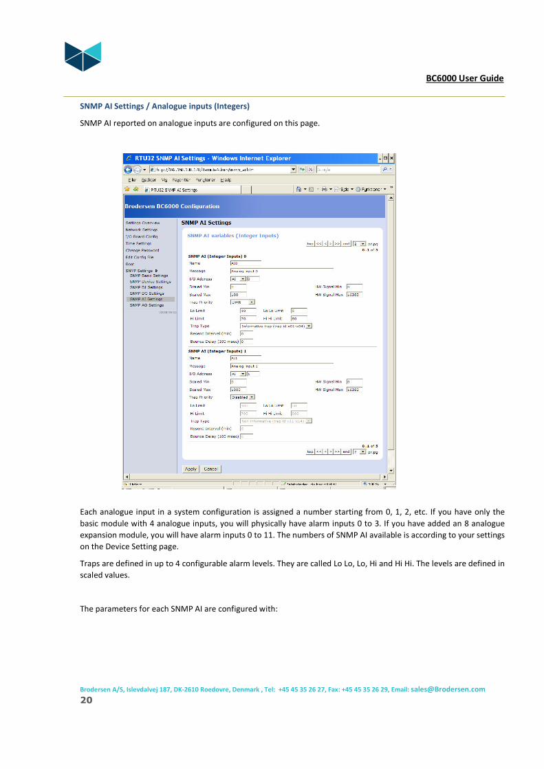
SNMP AI Settings / Analogue inputs (Integers)
SNMP AI reported on analogue inputs are configured on this page.
Each analogue input in a system configuration is assigned a number starting from 0, 1, 2, etc. If you have only the
basic module with 4 analogue inputs, you will physically have alarm inputs 0 to 3. If you have added an 8 analogue
expansion module, you will have alarm inputs 0 to 11. The numbers of SNMP AI available is according to your settings
on the Device Setting page.
Traps are defined in up to 4 configurable alarm levels. They are called Lo Lo, Lo, Hi and Hi Hi. The levels are defined in
scaled values.
The parameters for each SNMP AI are configured with:

BC6000 User Guide
Brodersen A/S, Islevdalvej 187, DK-2610 Roedovre, Denmark , Tel: +45 45 35 26 27, Fax: +45 45 35 26 29, Email: [email protected]
21
Name / Description of input: (text)
Description of the actual input. It could be UPS voltage level, in house temperature etc. Max.30 characters.
Message / Description of alarm: (text)
Description of the alarm event, like UPS voltage level failure etc. Max.255 characters
I/O Address
See the section for I/O addressing.
Scaled Min.
Defines the scaled minimum value (the scaled value is the value you want to get/read at the manager).
Scaled Max.
Defines the scaled minimum value (the scaled value is the value you want to get/read at the manager).
HW Signal Min.
HW signal min is the minimum value for the physical input. Normally it is 0.
HW Signal Max.
HW signal max is the maximum value for the physical input. If the AI has resolution of 14bit it is 16383, and if it is
12bit it is 4095. In general the BC6000 AI is 14bit and expansion module AI is 12 bit.
Trap Priority
Enables and define Trap priority. There are 6 possibilities;
Disabled (1) – disable Trap for this AI
Warning (2) – send warning Trap
Minor (3) – send minor Trap
Major (4) – send major Trap
Critical (5) – send critical Trap
Limit (6) – send limit information Trap
If you select 2-6 you will receive Trap type for each alarm level e.g. a HiHi (high-high) Trap alarm.
If priority 2-5 you get the selected priority for all alarm levels. The value and other info will still be available in the
Trap.
BC6000 User Guide
Brodersen A/S, Islevdalvej 187, DK-2610 Roedovre, Denmark , Tel: +45 45 35 26 27, Fax: +45 45 35 26 29, Email: [email protected]
22
Limit level settings
You can define trap alarms in 4 levels – LoLo, Lo, Hi and HiHi. Level is defined as Scaled Value. If you don’t want to
use all levels, you must define the range to be either very high or very low so the actual levels are not reached at any
time.
Trap Type
The Trap can be select if it should be as informative or none–informative type. If informative the Trap contains all
user variables, descriptions and texts.
If none-informative Trap it contain only value and priority – and readable ASCII are not transmitted.
Resend Interval (min)
Define the resend interval in minutes. If set to 0 the Trap is only send once.
Bounce Delay (100 msec)
Defines how many milliseconds the actual level should be reached before the alarm Trap is sent.

BC6000 User Guide
Brodersen A/S, Islevdalvej 187, DK-2610 Roedovre, Denmark , Tel: +45 45 35 26 27, Fax: +45 45 35 26 29, Email: [email protected]
23
SNMP AO Settings / Analogue output (Integers)
SNMP AO reported on analogue outputs are configured on this page.
Each analogue output in a system configuration is assigned a number starting from 0, 1, 2, etc. If you have only the
basic module with 2 analogue outputs, you will physically have analogue outputs 0 to 1. If you have added a 4
analogue expansion module, you will have outputs 0 to 5. The numbers of SNMP AO available is according to your
settings on the Device Setting page.
The analogue outputs can be controlled with SNMP Set commands. Each output is defined by an OID id in the MIB
file. Note that you use the scaled resolution when setting values.
Traps are defined in up to 4 configurable alarm levels for the output. They are called Lo Lo, Lo, Hi and Hi Hi. The
levels are also defined in scaled values.
The parameters for each SNMP AO are configured with:
Name / Description of output: (text)
Description of the actual output. It could be air conditioning system setpoint etc. Max.30 characters.
Message / Description of alarm/info: (text)
Description of the event, like A/C setpoint adjusted to low level. Max.255 characters.

BC6000 User Guide
Brodersen A/S, Islevdalvej 187, DK-2610 Roedovre, Denmark , Tel: +45 45 35 26 27, Fax: +45 45 35 26 29, Email: [email protected]
24
I/O Address
See the section for I/O addressing.
Scaled Min.
Defines the scaled minimum value (the scaled value is the value you want to set/write at the manager).
Scaled Max.
Defines the scaled maximum value (the scaled value is the value you want to set/write at the manager).
HW Signal Min.
HW signal min is the minimum value for the physical output resolution. Normally it is 0.
HW Signal Max.
HW signal max is the maximum resolution value for the physical output. If the AO has resolution of 14bit it is 16383,
and if it is 12bit it is 4095. In general the BC6000 internal AI is 14bit and expansion module AI is 12 bit.
Trap Priority
Enables and define Trap priority. There are 6 possibilities;
Disabled (1) – disable Trap for this AO
Warning (2) – send warning Trap
Minor (3) – send minor Trap
Major (4) – send major Trap
Critical (5) – send critical Trap
Limit (6) – send limit information Trap
If you select send limit Trap, you will receive Trap type for each alarm level e.g. a HiHi (high-high) Trap alarm. If
priority 2-5 you get the selected priority for all alarm levels. The value and other info will still be available in the Trap.
Limit level settings
You can define trap alarms in 4 levels – LoLo, Lo, Hi and HiHi. Level is defined as Scaled Value. If you don’t want to
use all levels, you must define the range to be either very high or very low so the actual levels are not reached at any
time.
BC6000 User Guide
Brodersen A/S, Islevdalvej 187, DK-2610 Roedovre, Denmark , Tel: +45 45 35 26 27, Fax: +45 45 35 26 29, Email: [email protected]
25
Trap Type
The Trap can be select if it should be as informative or none–informative type. If informative the Trap contains all
user variables, descriptions and texts.
If none-informative Trap it contain only value and priority – and readable ASCII are not transmitted.
Resend Interval (min)
Define the resend interval in minutes. If set to 0 the Trap is only send once.
4.2.2 I/O Addressing
Introduction
The addressing of I/Os in the configuration pages are actually quite simple if you understand the structure. The
addressing is as standard suppose to be direct to physical embedded I/Os and I/Os in expansion modules. See section
about optional addressing if you require more local control of special handling of events, grouping of alarms etc.
Note that in addressing everything is counted from 0 (zero). That means that the first input will be addressed as 0,
the second as 1 etc.
In Appendix 1 you will find a I/O addressing guide which will be helpful when you read the next sections about I/O
addressing.
Addressing of digital I/Os – DI/DO
DI and DO is Boolean data types (single bits). At addressing the bits are bundled in words (sections of 16 bits) which is
defined as “modules”.
For each DI or DO you must define:
• I/O type: DI or DO
• Module no: 0….n
• Bit no: 0…15
Example:
Physical input placed furthest to right on the BC6000 has address DI-0-15 as;
- it is the first DI word (bundle of 16 digital input bits) = module 0
- it is the last bit in the word = bit no 15
When you add I/O expansion modules to your BC6000, you will count the modules (words) from the basic module
and out to the last expansion module – and note that each type (DI, DO) is counted separately.

BC6000 User Guide
Brodersen A/S, Islevdalvej 187, DK-2610 Roedovre, Denmark , Tel: +45 45 35 26 27, Fax: +45 45 35 26 29, Email: [email protected]
26
Addressing of analogue I/Os – AI/AO
AI and AO are Word data types. At addressing they are just counted from the basic module to that last expansion
module. And note that each type (AI, AO) is counted separately.
Example:
Physical analogue input placed furthest to right on the BC6000 has address AI-3 as there is 4 AIs on the basic module
and the last one will be addressed =3 (the first 3 AIs has address 0, 1 and 2).
Optional Addressing - VIO
In all drop down addressing menus you will find that you can select the VIO option instead of e.g. DI or AI. This
optional addressing is only used if you want to use I/O’s from another user program. In this case the SNMP OIDs will
not be linked to physical I/Os but are available to be linked to either a Embedded C or SoftPLC program. The VIO a
range of Virtual I/Os in a database. This database can be accessed by STRATON SoftPLC or your own program in C,
VBA, C# etc. Contact Brodersen Controls A/S support if you want to learn more.
5 OID Structure and MIB
5.1 Introduction
OID structure is in general structured as defined in the BC6000 MIB file RTU32_2.MIB. The MIB file is supporting
tables as commonly used by SNMP managers.
The MIB file for the BC6000 SNMP module is used for defining the SNMP variables for SNMP Managers.
5.2 MIB and OID – general information
The MIB file for the BC6000 SNMP module is used for defining the SNMP variables for an SNMP Manager. The MIB
file is entered in the SNMP Manager software and compiled to configure the SNMP manager to work with BC6000.
The primary OID is defined according to the RFC specifications for SNMP, and the unique OID address for the BC6000
as an alarm, monitoring and control device in networks are:
1.3.6.1.4.1.24122.2…..
(iso.org.dod.internet.private.enterprises……)
- where the “24122” is the Brodersen Systems A/S branch id and the “.2” is the unique BC6000 device id.

BC6000 User Guide
Brodersen A/S, Islevdalvej 187, DK-2610 Roedovre, Denmark , Tel: +45 45 35 26 27, Fax: +45 45 35 26 29, Email: [email protected]
27
The Microsoft©
WinCE operating system in BC6000 will also provide basic information about the basic IPC hardware,
network interfaces etc. The OID for this is defined in the standard MIBII – and will be recognized by the enterprise id
311 which belongs to Microsoft©
.
OID overview can be read in RTU32_2.MIB file, where a MIB view is listed in the start of the file. In the next section
you will find the OID structure where we have added some comments we consider necessary to understand the
structure and define OID addresses for each single input/output information.
5.3 MIB and OID - overview
Below the OID structure is listed with some notes (in italic). The MIB view explains in short form that OID structure –
and if you require details you may find every OID described later in the MIB file.
Anyway there is some general information we consider important to list here;
• The {rtu32a2} equals the general part of the IOD address: 1.3.6.1.4.1.24122.2 – and you can then build up
the OID for a single entry by adding this to the address in the MIB view. As example will the value for the
first input Boolean have the OID address
1.3.6.1.4.1.24122.2.3.2.1.3.1
• Some notes are marked in the MIB view – see end of view for details.
-- ***********************************************************************
-- MIB View (short form)
-- ***********************************************************************
-- info {rtu32a2}.1
-- infoVersion {rtu32a2}.1.1.0
-- infoTrapIdx {rtu32a2}.1.2.0 (see note 1)
-- infoConfigCmd {rtu32a2}.1.3.0
-- infoConfigCmdResult {rtu32a2}.1.4.0
-- infoTableSizeDevice {rtu32a2}.1.11.0
-- infoTableSizeInpBool {rtu32a2}.1.12.0
-- infoTableSizeInpInt {rtu32a2}.1.13.0
-- infoTableSizeOutBool {rtu32a2}.1.15.0
-- infoTableSizeOutInt {rtu32a2}.1.16.0
-- infoDebugString {rtu32a2}.1.101.0
-- infoDebugNumber {rtu32a2}.1.102.0
-- device {rtu32a2}.2
-- dtNumber {rtu32a2}.2.1.0
-- dtDeviceTable {rtu32a2}.2.2
-- dtDeviceEntry {rtu32a2}.2.2.1
-- dtDeviceIndex {rtu32a2}.2.2.1.1.row(1..dtNumber)
-- dtDeviceString {rtu32a2}.2.2.1.2.row(1..dtNumber)
-- inpboolean {rtu32a2}.3

BC6000 User Guide
Brodersen A/S, Islevdalvej 187, DK-2610 Roedovre, Denmark , Tel: +45 45 35 26 27, Fax: +45 45 35 26 29, Email: [email protected]
28
-- ibInpBoolNumber {rtu32a2}.3.1.0
-- ibInpBoolTable {rtu32a2}.3.2
-- ibInpBoolEntry {rtu32a2}.3.2.1
-- ibInpBoolIndex {rtu32a2}.3.2.1.1.row(1..ibInpBoolNumber)
-- ibInpBoolAlias {rtu32a2}.3.2.1.2.row(1..ibInpBoolNumber)
-- ibInpBoolValue {rtu32a2}.3.2.1.3.row(1..ibInpBoolNumber)
-- ibInpBoolTrapActive {rtu32a2}.3.2.1.4.row(1..ibInpBoolNumber)
-- ibInpBoolMsg {rtu32a2}.3.2.1.5.row(1..ibInpBoolNumber)
-- ibInpBoolTrapPriority {rtu32a2}.3.2.1.6.row(1..ibInpBoolNumber)
-- ibInpBoolInformativeTrap {rtu32a2}.3.2.1.7.row(1..ibInpBoolNumber)
-- ibInpBoolOrigin {rtu32a2}.3.2.1.8.row(1..ibInpBoolNumber)
-- ibInpBoolModuleNo {rtu32a2}.3.2.1.9.row(1..ibInpBoolNumber)
-- ibInpBoolBitNo {rtu32a2}.3.2.1.10.row(1..ibInpBoolNumber)
-- ibInpBoolSendTrapAt {rtu32a2}.3.2.1.11.row(1..ibInpBoolNumber)
-- ibInpBoolTrapResend {rtu32a2}.3.2.1.12.row(1..ibInpBoolNumber)
-- ibInpBoolResendCount {rtu32a2}.4.2.1.13.row(1..ibInpBoolNumber)
-- ibInpBoolBounceDelay {rtu32a2}.3.2.1.14.row(1..ibInpBoolNumber)
-- inpinteger {rtu32a2}.4
-- iiInpIntNumber {rtu32a2}.4.1.0
-- iiInpIntTable {rtu32a2}.4.2
-- iiInpIntEntry {rtu32a2}.4.2.1
-- iiInpIntIndex {rtu32a2}.4.2.1.1.row(1..iiInpIntNumber)
-- iiInpIntAlias {rtu32a2}.4.2.1.2.row(1..iiInpIntNumber)
-- iiInpIntValue {rtu32a2}.4.2.1.3.row(1..iiInpIntNumber)
-- iiInpIntAlarmLevel {rtu32a2}.4.2.1.4.row(1..iiInpIntNumber)
-- iiInpIntMsg {rtu32a2}.4.2.1.5.row(1..iiInpIntNumber)
-- iiInpIntTrapPriority {rtu32a2}.4.2.1.6.row(1..iiInpIntNumber)
-- iiInpIntInformativeTrap {rtu32a2}.4.2.1.7.row(1..iiInpIntNumber)
-- iiInpIntOrigin {rtu32a2}.4.2.1.8.row(1..iiInpIntNumber)
-- iiInpIntModuleNo {rtu32a2}.4.2.1.9.row(1..iiInpIntNumber)
-- iiInpIntLoLoLimit {rtu32a2}.4.2.1.10.row(1..iiInpIntNumber)
-- iiInpIntLoLimit {rtu32a2}.4.2.1.11.row(1..iiInpIntNumber)
-- iiInpIntHiLimit {rtu32a2}.4.2.1.12.row(1..iiInpIntNumber)
-- iiInpIntHiHiLimit {rtu32a2}.4.2.1.13.row(1..iiInpIntNumber)
-- iiInpIntTrapResend {rtu32a2}.4.2.1.14.row(1..iiInpIntNumber)
-- iiInpIntResendCount {rtu32a2}.4.2.1.15.row(1..iiInpIntNumber)
-- iiInpIntBounceDelay {rtu32a2}.4.2.1.16.row(1..iiInpIntNumber)
-- iiInpIntScaleMin {rtu32a2}.4.2.1.17.row(1..iiInpIntNumber)
-- iiInpIntScaleMax {rtu32a2}.4.2.1.18.row(1..iiInpIntNumber)
-- iiInpIntAIMin {rtu32a2}.4.2.1.19.row(1..iiInpIntNumber)
-- iiInpIntAIMax {rtu32a2}.4.2.1.20.row(1..iiInpIntNumber)
-- outboolean {rtu32a2}.6
-- obOutBoolNumber {rtu32a2}.6.1.0

BC6000 User Guide
Brodersen A/S, Islevdalvej 187, DK-2610 Roedovre, Denmark , Tel: +45 45 35 26 27, Fax: +45 45 35 26 29, Email: [email protected]
29
-- obOutBoolTable {rtu32a2}.6.2
-- obOutBoolEntry {rtu32a2}.6.2.1
-- obOutBoolIndex {rtu32a2}.6.2.1.1.row(1..obOutBoolNumber)
-- obOutBoolAlias {rtu32a2}.6.2.1.2.row(1..obOutBoolNumber)
-- obOutBoolValue {rtu32a2}.6.2.1.3.row(1..obOutBoolNumber)
-- obOutBoolTrapActive {rtu32a2}.6.2.1.4.row(1..obOutBoolNumber)
-- obOutBoolMsg {rtu32a2}.6.2.1.5.row(1..obOutBoolNumber)
-- obOutBoolTrapPriority {rtu32a2}.6.2.1.6.row(1..obOutBoolNumber)
-- obOutBoolInformativeTrap {rtu32a2}.6.2.1.7.row(1..obOutBoolNumber)
-- obOutBoolOrigin {rtu32a2}.6.2.1.8.row(1..obOutBoolNumber)
-- obOutBoolModuleNo {rtu32a2}.6.2.1.9.row(1..obOutBoolNumber)
-- obOutBoolBitNo {rtu32a2}.6.2.1.10.row(1..obOutBoolNumber)
-- obOutBoolSendTrapAt {rtu32a2}.6.2.1.11.row(1..obOutBoolNumber)
-- obOutBoolTrapResend {rtu32a2}.6.2.1.12.row(1..obOutBoolNumber)
-- obOutBoolResendCount {rtu32a2}.4.2.1.13.row(1..obOutBoolNumber)
-- outinteger {rtu32a2}.7
-- oiOutIntNumber {rtu32a2}.7.1.0
-- oiOutIntTable {rtu32a2}.7.2
-- oiOutIntEntry {rtu32a2}.7.2.1
-- oiOutIntIndex {rtu32a2}.7.2.1.1.row(1..oiOutIntNumber)
-- oiOutIntAlias {rtu32a2}.7.2.1.2.row(1..oiOutIntNumber)
-- oiOutIntValue {rtu32a2}.7.2.1.3.row(1..oiOutIntNumber)
-- oiOutIntAlarmLevel {rtu32a2}.7.2.1.4.row(1..oiOutIntNumber)
-- oiOutIntMsg {rtu32a2}.7.2.1.5.row(1..oiOutIntNumber)
-- oiOutIntTrapPriority {rtu32a2}.7.2.1.6.row(1..oiOutIntNumber)
-- oiOutIntInformativeTrap {rtu32a2}.7.2.1.7.row(1..oiOutIntNumber)
-- oiOutIntOrigin {rtu32a2}.7.2.1.8.row(1..oiOutIntNumber)
-- oiOutIntModuleNo {rtu32a2}.7.2.1.9.row(1..oiOutIntNumber)
-- oiOutIntLoLoLimit {rtu32a2}.7.2.1.10.row(1..oiOutIntNumber)
-- oiOutIntLoLimit {rtu32a2}.7.2.1.11.row(1..oiOutIntNumber)
-- oiOutIntHiLimit {rtu32a2}.7.2.1.12.row(1..oiOutIntNumber)
-- oiOutIntHiHiLimit {rtu32a2}.7.2.1.13.row(1..oiOutIntNumber)
-- oiOutIntTrapResend {rtu32a2}.7.2.1.14.row(1..oiOutIntNumber)
-- oiOutIntResendCount {rtu32a2}.7.2.1.15.row(1..oiOutIntNumber)
-- oiOutIntScaleMin {rtu32a2}.7.2.1.16.row(1..oiOutIntNumber)
-- oiOutIntScaleMax {rtu32a2}.7.2.1.17.row(1..oiOutIntNumber)
-- oiOutIntAOMin {rtu32a2}.7.2.1.18.row(1..oiOutIntNumber)
-- oiOutIntAOMax {rtu32a2}.7.2.1.19.row(1..oiOutIntNumber)
-- last {rtu32a2}.2.100
NOTE 1: The infoTrapIdx OID is a sequential counter that gives any trap sent from the device a unique number. This
OID is used for acknowledgement of Traps. An additional OID called infoTrapAckx can be implemented for the

BC6000 User Guide
Brodersen A/S, Islevdalvej 187, DK-2610 Roedovre, Denmark , Tel: +45 45 35 26 27, Fax: +45 45 35 26 29, Email: [email protected]
30
manager to return the unique id of a Trap to report acknowledge of the actual Trap. The BC6000 Agent will then stop
the resending Trap procedure.

BC6000 User Guide
Brodersen A/S, Islevdalvej 187, DK-2610 Roedovre, Denmark , Tel: +45 45 35 26 27, Fax: +45 45 35 26 29, Email: [email protected]
31
6. Installation and Wiring
6.1 Mounting
The BC6000 SNMP module and I/O expansion modules are mounted on a 35mm DIN rail.
Mounting De-mounting
6.2 Power supply
The module is powered by +24-60VDC or -24-60VDC.
Supply input: Supply output 12VDC:
6.3 Digital inputs
Digital inputs for alarms are 24-60VDC bipolar inputs. Wiring according to figure below:
1
2
2
1
+ -
C
0 1 2 3 4 5 6 7
In C
0 1 2 3 4 5 6 7
B
C CvA
iAvB
iB
Externalsupply10 - 30V DC
+
-

BC6000 User Guide
Brodersen A/S, Islevdalvej 187, DK-2610 Roedovre, Denmark , Tel: +45 45 35 26 27, Fax: +45 45 35 26 29, Email: [email protected]
32
6.4 Relay outputs
The relays provide potential free normally open (NO) contacts.
6.5 Analogue inputs
The analogue inputs are sourced by either the 12VDC output on the BC6000 SNMP or from the general application
current source.
6.6 Analogue outputs
The analogue output sources directly 4-20mA.
0 1 2 3
D
NC NC
Rela
y 0
Rela
y 1
Rela
y 2
Rela
y 3
VV
A
Voltageor
current
C CvA
iAvB
iB
I 0V C
3
C 12V I
2
V C
3
+ -

BC6000 User Guide
Brodersen A/S, Islevdalvej 187, DK-2610 Roedovre, Denmark , Tel: +45 45 35 26 27, Fax: +45 45 35 26 29, Email: [email protected]
33
6.7 I/O Expansion modules
The I/O Extension modules are connected via Brodersen LocalBus cable.
You can find details of the different I/O Expansion modules in the I/O Expansion overview brochure and selection
guide. And if you need detailed data sheets that are also available from our home page www.brodersensystems.com.
C
Local bus connection
Additional expansionmodules

BC6000 User Guide
Brodersen A/S, Islevdalvej 187, DK-2610 Roedovre, Denmark , Tel: +45 45 35 26 27, Fax: +45 45 35 26 29, Email: [email protected]
34
7. Technical Data
For technical data details – see RTU32 PLC Data sheet. Available on our website.

BC6000 User Guide
Brodersen A/S, Islevdalvej 187, DK-2610 Roedovre, Denmark , Tel: +45 45 35 26 27, Fax: +45 45 35 26 29, Email: [email protected]
35
Appendix 1 – I/O Addressing
Addressing guide – please ignore the ZI and ZO addressing as it is not used in BC6000.