Embed Size (px)
Citation preview

4000 SERIES AUTOMATIC SWITCHOVER
MANIFOLD Operation & Maintenance Manual
Allied Healthcare Products, Inc. 1720 Sublette Avenue - St. Louis, MO 63110
Telephone: 800-444-3954 - Fax: 314-771-1806 Catalog No. S188-354-001 Rev. B
MANIFOLDS ARE AVAILABLE FOR THE FOLLOWING GASES:
OXYGEN CARBON DIOXIDE
NITROGEN MEDICAL AIR
NITROUS OXIDE

Table of Contents
Subject Page
Introduction 1
Key Elements 2
Manifold Operation 3-4
Factory Settings 3
Schematic Diagram 4
Flow Charts 5
Site Selection 6
Installation 7
Manifold Outline 8
Method Of Operation 10
Safety Features 11
Remote Alarm Wiring Diagram 13
Leak Test 14
Ordering Information 15
Repair Parts List 16
Trouble Shooting 17-18
Limited Warranty Back Cover
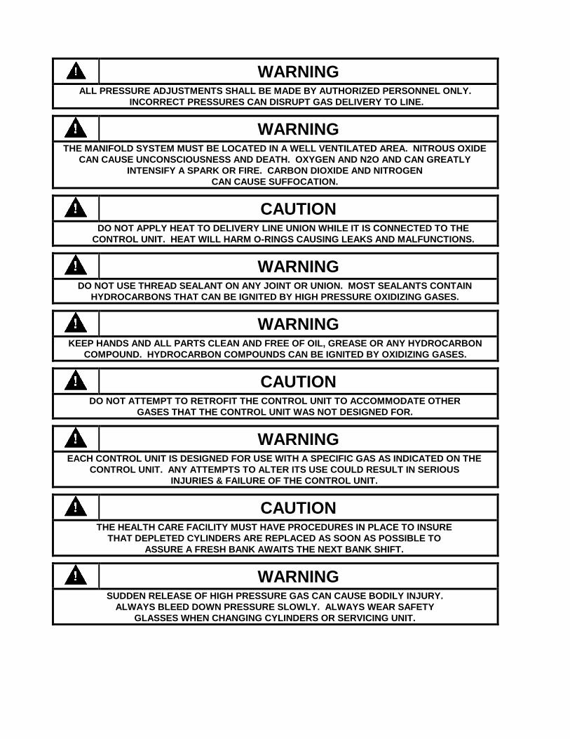
WARNING ALL PRESSURE ADJUSTMENTS SHALL BE MADE BY AUTHORIZED PERSONNEL ONLY.
INCORRECT PRESSURES CAN DISRUPT GAS DELIVERY TO LINE.
WARNING
THE MANIFOLD SYSTEM MUST BE LOCATED IN A WELL VENTILATED AREA. NITROUS OXIDE
CAN CAUSE UNCONSCIOUSNESS AND DEATH. OXYGEN AND N2O AND CAN GREATLY
INTENSIFY A SPARK OR FIRE. CARBON DIOXIDE AND NITROGEN
CAN CAUSE SUFFOCATION.
CAUTION
DO NOT APPLY HEAT TO DELIVERY LINE UNION WHILE IT IS CONNECTED TO THE
CONTROL UNIT. HEAT WILL HARM O-RINGS CAUSING LEAKS AND MALFUNCTIONS.
WARNING
DO NOT USE THREAD SEALANT ON ANY JOINT OR UNION. MOST SEALANTS CONTAIN
HYDROCARBONS THAT CAN BE IGNITED BY HIGH PRESSURE OXIDIZING GASES.
WARNING
KEEP HANDS AND ALL PARTS CLEAN AND FREE OF OIL, GREASE OR ANY HYDROCARBON
COMPOUND. HYDROCARBON COMPOUNDS CAN BE IGNITED BY OXIDIZING GASES.
CAUTION
DO NOT ATTEMPT TO RETROFIT THE CONTROL UNIT TO ACCOMMODATE OTHER
GASES THAT THE CONTROL UNIT WAS NOT DESIGNED FOR.
WARNING
EACH CONTROL UNIT IS DESIGNED FOR USE WITH A SPECIFIC GAS AS INDICATED ON THE
CONTROL UNIT. ANY ATTEMPTS TO ALTER ITS USE COULD RESULT IN SERIOUS
INJURIES & FAILURE OF THE CONTROL UNIT.
CAUTION
THE HEALTH CARE FACILITY MUST HAVE PROCEDURES IN PLACE TO INSURE
THAT DEPLETED CYLINDERS ARE REPLACED AS SOON AS POSSIBLE TO
ASSURE A FRESH BANK AWAITS THE NEXT BANK SHIFT.
WARNING
SUDDEN RELEASE OF HIGH PRESSURE GAS CAN CAUSE BODILY INJURY.
ALWAYS BLEED DOWN PRESSURE SLOWLY. ALWAYS WEAR SAFETY
GLASSES WHEN CHANGING CYLINDERS OR SERVICING UNIT.

Introduction
The dual line regulator 4000 Series Medical Gas Manifold has been cleaned, tested and prepared at the factory for the specific gas indicated. The unit complies with the National Fire Protection Association (NFPA) standard 99 “Health Care Facilities”. All critical connections are gas specific and are designed to eliminate supply gas errors. This manual is supplied to give the health care facility personnel installation, operation and maintenance instructions. Keep this manual with the manifold for convenient reference. The dual line regulator/single vent 4000 Series Medical Gas Manifold will need right and left header bars and pigtails that must be ordered separately. The installed system will automatically switch to the reserve bank when the primary bank is depleted. When the depleted cylinders are replaced with full ones the system will automatically reset itself in preparation for the next bank change. The primary side is the bank in use and the reserve side is the bank on “Reserve”. This designation will automatically change from left to right and right to left as each bank is depleted and, in turn, refitted with full gas cylinders. The empty LED indicator will show a depleted bank by turning red. When the system is reset, by replacing the depleted cylinders, the indicator will turn yellow. If the manifold is connected to the health care facility’s central alarm system that will also indicate that the bank was depleted and, in turn, reset. The only manual activity the 4000 Series Medical Gas Manifold requires is the changing of the depleted cylinders. The 4000 Series Manifold is available in five standard models, each specifically designed for its gas service. The gas standard services offered are: oxygen, nitrogen, nitrous oxide, medical air and carbon dioxide. Manifolds may be obtained in these gas services as standard units. The manifold unit and header bar sections can be ordered complete by calling your Allied Sales Representative. Header bar sections can also be obtained by ordering the number and type needed to complete the manifold from the list on Page 15. NFPA requires at least the number of cylinders for an average twenty-four (24) hour day’s supply per bank, with a minimum of two cylinders per bank. There are two methods of mounting the 4000 Series Manifold; either floor or wall (standard) systems. With the wall type, the manifold is attached to a wall bracket and cylinders stand next to the wall. The floor type may stand free, in the center of a room, with the manifold supported on a stand. The customer is responsible for design and manufacturing of the floor type stand. Three pressure gauges on the front of the control cabinet indicate left bank, right bank and line pressures. Primary pressure regulator heaters are included on nitrous oxide and carbon dioxide 4000 Series Manifolds.Regulator frosting may cause pressure fluctuations.
WARNING
REGULATORS MAY FREEZE UP IF THEY ARE USED AT HIGH FLOW RATES OR IN LOW
TEMPERATURES WITHOUT A HEATER.
Definitions
Shall: Is intended to indicate a requirement as stipulated by a standard or code.
Should: Is intended to indicate a recommendation or a suggestion or an item of advice, but not required.
Note: Is intended to indicate additional information that will be helpful.
Caution: Is intended to indicate that there is a slight chance of bodily injury or property damage. There is also the possibility of a manifold shutdown if the “Caution” is not heeded. This will be highlighted by an outline box.
Warning: Is intended to indicate that there is a moderate chance of bodily injury, death or property damage. This will be highlighted by an outline box.
1

Manifold Key Elements
2
RIGHT BANK
HIGH PRESSURE
REGULATOR
PNEUMATIC
SWITCHING
VALVE
LINE
PRESSURE
GAUGE
LINE
OUTLET
EXHAUST
VENT
BALL
VALVE
CHECK
VALVES(NOT
SHOWN)
RIGHT LINE
PRESSURE
REGULATOR
POWER
SUPPLY
LEFT BANK
HIGH
PRESSURE
GAUGE
RIGHT BANK
HIGH
PRESSURE
GAUGE
SOLENOID
VALVE LT.
BANK SOLENOID
VALVE RT.
BANK
LEFT BANK HIGH
PRESSURE
REGULATOR
SERVICE LINE
PRESSURE
RELIEF
LEFT BANK
INLET
VALVE
RIGHT
BANK
INLET
VALVE
LEFT LINE
PRESSURE
REGULATOR
AC POWER
CONNECTION
PC BOARD
CHECK
VALVES(NOT
SHOWN)

Key Elements
1. A pressure control manifold that maintains constant pressure to the pipeline and enables smooth uninterrupted switchover from the “in use” to the “reserve” cylinders.
2. A 115VAC 0.2 Amps / 230 VAC 0.1 Amps input, 5/15 VDC output power supply. Power supply includes dry
contacts for local and remote alarm connections.
3. Control panel indicator LED’s indicate the status of the left and right cylinder banks. The “In Service” is indicated by the green LED while the reserve cylinder bank is indicated by the yellow “Reserve Ready” LED. A red “Replace Empty Cylinders” LED indicates a depleted cylinder bank.
4. Individual pressure gauges allow monitoring of left and right cylinder bank pressure, and, pipeline delivery
pressure.
5. Master valves used to shut off gas in emergency situations, should normally be left open.
6. Physical properties of manifold:
Dimensions (In inches): 25” H x 16-5/8” W x 6 “ D Weight: 60 LBS Without Header Bars
Factory Settings
.
Relief Valve Settings Supply Line 75 PSI All gases except nitrogen
Supply Line 225 PSI Nitrogen
High pressure regulators
325 PSI All gases
Regulator Settings High Pressure Regulator
250 PSI All gases except Nitrogen
275 PSI Nitrogen
Low Pressure Regulator
55 PSI All gases except Nitrogen
180 PSI Nitrogen
WARNING
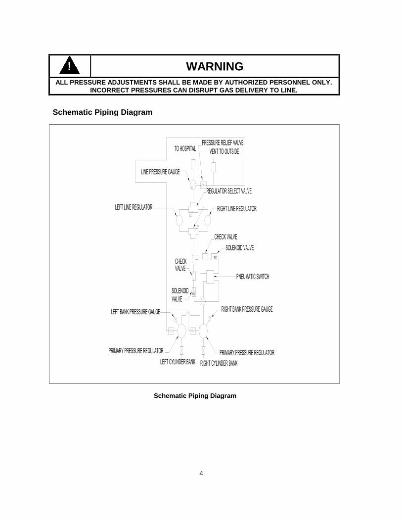
ALL PRESSURE ADJUSTMENTS SHALL BE MADE BY AUTHORIZED PERSONNEL ONLY.
INCORRECT PRESSURES CAN DISRUPT GAS DELIVERY TO LINE.
3
WARNING
ALL PRESSURE ADJUSTMENTS SHALL BE MADE BY AUTHORIZED PERSONNEL ONLY.
INCORRECT PRESSURES CAN DISRUPT GAS DELIVERY TO LINE.
Schematic Piping Diagram
Schematic Piping Diagram
4

Flow Charts – 4000 Manifold 4000 SERIES MANIFOLD (ALL GASES EXCEPT NITROGEN) OUTLET PRESSURE SET AT 55 PSI
Pressure - vs- Flow
30
35
40
45
50
55
15 20 25 30 35 40 45 50 55 60 65 70
Flow Rate (SCFM)
Ou
tlet
Pre
ssu
re (
PS
I)
4000 SERIES MANIFOLD (NITROGEN) OUTLET PRESSURE SET AT 180 PSI
Pressure - vs- Flow
30
80
130
180
230
15 20 25 30 35 40 45 50 55 60 65 70
Flow Rate (SCFM)
Ou
tlet
Pre
ssu
re (
PS
I)
5

Site Selection
The proximity to the health care facility’s central piping system is the obvious, but not the only reason for choosing an installation site. Ventilation, temperature extremes, etc. must also be considered. Refer to NFPA 99 for specific location requirements. The manifold system shall be installed in a well ventilated area. None of the gas specific manifolds are designed for a flammable gas. Some of the gases will actively support combustion. The gases with high oxidizer content, such as oxygen and nitrous oxide, shall never have grease, oil, or other combustibles come in contact with any part of the system. Also, tools and hands shall be kept clean and free of oil or grease. Spontaneous combustion may occur. There shall be no open flame in the manifold area. This includes matches, smoking material, pilot lights, etc. There shall be no spark generating equipment in the manifold area. This includes motors, switches, etc. Even a gas as apparently harmless as nitrogen must be installed in a well ventilated area. If the nitrogen gas were allowed to build up to a point, in an unventilated area, where all the oxygen was pushed out, then a person entering this area would run the risk of suffocation. Carbon dioxide is the primary waste gas the lungs try to exhale. The carbon dioxide in the blood must be removed before oxygen can be absorbed. Carbon dioxide inhaled in the air inhibits the lungs availability to remove carbon dioxide from the blood. As the carbon dioxide concentration increases so does breathing difficulty. In the extreme case, a high concentration of carbon dioxide can cause the equivalent to suffocation even with some oxygen present. Nitrous oxide is an anesthetic gas. It can cause unconsciousness and even death.
WARNING
THE MANIFOLD SYSTEM MUST BE LOCATED IN A WELL VENTILATED AREA. NITROUS OXIDE CAN
CAUSE UNCONSCIOUSNESS AND DEATH. OXYGEN AND O2/CO2 < 7% CAN GREATLY INTENSIFY A
SPARK OR FIRE. CARBON DIOXIDE AND NITROGEN CAN CAUSE SUFFOCATION.
The health care facility’s central forced air heating and air conditioning system should never have a return duct
connected to the manifold area. The manifold area should always be vented to the outside away from any intake
ducts. Refer to NFPA 99.
The manifold is designed to operate in a temperature range between 40° and 130°F. Relative humidity should not exceed 90%. If the humidity is high and the temperature is low, frost and/or ice could interfere with the performance of the regulators. Allied Healthcare Products, Inc. (Allied) includes a set of heaters as standard equipment with carbon dioxide and nitrous oxide control units that will preheat gas from the cylinders minimizing the frost problem. Since carbon dioxide and nitrous oxide are both liquid when in the compressed gas cylinder, the phase change (from liquid to gas) cooling is added to the gas expansion cooling. Thus the frost will form much quicker with carbon dioxide and nitrous oxide than with nitrogen, oxygen, and medical air. Under extreme conditions of high flow, the cylinders could become chilled to the point where droplets of liquid would pass down stream and harm the manifold and other health care equipment. Site selection should also take into consideration the handling convenience of the manifold and access to the loading docks. In the case of carbon dioxide and nitrous oxide the temperature shall not go below 65°F.
6
Uncrating
All parts should be kept in their crates until they are needed for assembly. Check the gas type of the components to be sure they are the items ordered. If damage is discovered during the uncrating and assembly process, contact the freight carrier and make a concealed damage report within seven (7) days. Allied will assist the claims process as much as possible, but it is the responsibility of the receiver to file any claims.
Minimum Equipment Needed
One Control Unit and a pair of corresponding cylinder header bars with pigtails is the minimum equipment needed to have a functioning manifold system. NFPA 99 requires a minimum of two cylinders per bank. Always install a balanced set of header bars for each manifold system, i.e. an equal number of cylinders per bank. Adding header bars and gas cylinders to each bank will not increase the maximum flow rate of the system, but it will increase the time between cylinder changes, i.e. double the number of cylinders (and header bars) and the time between cylinder changes will be doubled.
Installation
The 4000 Series Manifold meets the provisions of the National Fire Protection Association (NFPA) standard.
Control Unit The Control Cabinet is designed to be water resistant, but it is not waterproof. The Control Cabinet should be mounted
in a location protected from moisture. Suitable anchoring bolts and washers will be necessary for mounting (bolts are not furnished with the unit, 7/16” diameter bolts are recommended). The Control Cabinet must be mounted to a sound structure that is designed to handle the weight of the Control Cabinet. Keep the cabinet both horizontally and vertically level. If necessary, shim behind the back side. Since the Manifold Cabinet cover can be removed from the wall mounted main panel, the possibility of mixing up cabinets covers with different main panels exists. Both the main panel and manifold cabinet cover are labeled with a gas specific label and should be matched and returned to it’s original manifold.
Plumbing
Connect the delivery line union, located at the top center of the Control Unit, to the health care facility’s central piping
system. NFPA requires that a main shut off valve be installed between the manifold delivery line and the central piping system.
Be sure that the right and left header bar valves are turned off. Later in these Installation Instructions you will be
advised when and how these valves should be used.
7

Manifold Outline
Approximate floor space needed to install manifold and cross header bar sets.
Cylinder Overall Width Cylinder Overall Width
1 X 1 17 inches 9 X 9 73.5 inches
2 X 2 22 inches 10 X 10 94 inches
3 X 3 22 inches 11 X 11 94 inches
4 X 4 42.5 inches 12 X 12 114.5 inches
5 X 5 42.5 inches 13 X 13 114.5 inches
6 X 6 63 inches 14 X 14 125 inches
7 X 7 63 inches 15 X 15 125 inches
8 X 8 73.5 inches
8

CAUTION
DO NOT APPLY HEAT TO DELIVERY LINE UNION WHILE IT IS CONNECTED TO THE CONTROL UNIT.
HEAT WILL HARM O-RINGS, CAUSING LEAKS AND MALFUNCTIONS.
Check for proper venting to atmosphere as required by job specifications and/or NFPA 99, If the manifold is installed in an enclosed area, the safety relief valves must be vented to the outside atmosphere. On top of the control unit (to the right of the hospital supply line) a safety relief valve with a 1/4” NPT threaded fitting has been provided to attach a vent pipe. Provisions must be made to install this pipe to the outside atmosphere.
Electrical
The Manifold 4000 comes with a power supply that can accommodate either 115 VAC, 0.2 Amps or 230 VAC, 0.1 Amps power
input. See Wiring Diagram on page 13. The circuit board will display the status of the pressure in both banks with 3 LED's per
bank.
To connect power to the unit, route the incoming power lines through the conduit to the power terminal block. Connect the Neutral
wire to the terminal connection labeled N, connect the Line wire to the terminal connection labeled L connection and the ground
wire to the terminal connection labeled G.
The Manifold board is equipped with 2 Alarm Switch Outputs. These switch outputs are normally closed. If one or both sides are
low, a red LED will turn on and the alarm out put will be set (open) indicating a switch alarm. To use the outputs in conjunction
with the Impact Alarm system, connect the Manifolds AO1 or AO2 to one of the Impact Alarm 10 switch signal module SI inputs
and the Manifolds corresponding Gin to the Impact Alarm's corresponding GO input.
The Manifold circuit board will also monitor the pressure in both banks to detect a Double Drain condition, where gas is flowing
from both banks. If this condition is detected, the alarm output will be set and the primary sides green LED will be on while the
secondary's green LED will flash off and on.
Initialization
When you power up the Manifold for the first time. First connect power to the system. Both red LED's should turn on. Pressurize
one side, this will be the primary side, it's green LED will then turn on. Pressurize the other side and then its yellow LED will turn
on this is the secondary side.
In the event of a power failure the manifold will continue to operate properly but there will be no LED indications and there will be
no Alarm Signal outputs. Once power is returned the circuit board will assume that there has not been a switch over, thus which
ever side was the primary before the power failure will remain the primary. The software will monitor the pressure on both sides
and if the secondary is dropping but not the primary it will switch to the correct primary.
Header Bars
Divide the total quantity of header bar sections into two groups, one for the left bank and the other for the right bank of cylinders. There should be an equal number of cylinder inlets on each side of the manifold.
After the Manifold has been mounted, the header bars should be securely anchored to the wall (or Header Stand Kit) and carefully aligned and leveled. The union on each side of the bottom of the Manifold provides for a gas specific header bar connection. Proper alignment is necessary to assure a leak free installation. Support all header bars with firmly anchored wall brackets (or Header Stand Kits).
Space the wall brackets (or Header Stand Kits) to conform to the side of the header bars. The first wall bracket (or Header Stand Kit) on either side of the Manifold should be between the first two cylinder connections closest to the Manifold. A wall bracket (or Header Stand Kit) should be placed every third cylinder connection thereafter. If the manifold system purchased has two or less cylinder connections per side, no wall brackets (or Header Stand Kits) are needed.
9

WARNING
DO NOT USE THREAD SEALANT ON ANY JOINT OR UNION. MOST SEALANTS CONTAIN
HYDROCARBONS THAT CAN BE IGNITED BY HIGH PRESSURE OXIDIZING GASES.
Connect the header bar assembly to the master header valve fitting on the Control Unit. Use one wrench on the Manifold inlet connection and another on the header gas specific nut. Hold the Manifold inlet connection steady and tighten the header nut. This will prevent any twisting of internal components of the Manifold. Twisting of internal components may cause leaks. Check the alignment and level of the Manifold and header brackets. If there is an alignment problem loosen all the header bar mounting hardware. Adjust as needed and tighten.
Cylinder Pigtails
Allied offers two styles of flexible pigtails: coiled copper (oxygen and nitrous oxide) and braided stainless steel (nitrous oxide and all other gases). Refer to the Optional Equipment Section or contact your Allied Sales Representative. The braided pigtail offers greater ease of handling the gas cylinders. Both styles of pigtails have built-in check valves. The pigtail end that has the check valve is denoted by stamping on one of the flats of the CGA gas specific nut and/or a label indicating direction of flow. The direction of flow is from the cylinder to the header bar. NFPA 99 requires copper pigtails for Oxygen service.
Note: When installing the pigtails to the header bars be sure to note the flow direction of the pigtail.
Cylinders
Before pressuring the header bars, make sure all pigtails are properly connected. Remove the protective cylinder caps from the cylinders and store in a safe place for later use. Place and secure the cylinders in position. Connect each pigtail to a cylinder and tighten with a wrench. For additional information regarding the handling of gas cylinders, refer to the Compressed Gas Association (CGA) Pamphlet P-2, Section 4.1 for General Rules, Section 4.2 for Moving Cylinders and 4.3 for Storing Cylinders.
WARNING
KEEP HANDS AND ALL PARTS CLEAN AND FREE OF OIL, GREASE OR ANY HYDROCARBON
COMPOUND. HYDROCARBON COMPOUNDS CAN BE IGNITED BY OXIDIZING GASES.
Method of Operation
The 4000 Series Manifold delivers a regulated gas pressure through a wide range of flow rates to the health care facilities central gas piping system. The source of the gas is two banks of high pressure cylinders (usually H size). When a bank is depleted, the 4000 Series Manifold will automatically switch to the fresh bank delivering an uninterrupted gas supply to the health care facility. Change over shall be performed by a pneumatic valve contained in the manifold. In the event of an electrical power failure, no interruption of gas flow will occur. The manifold should not require any manual resetting or adjustments except for the replacement of depleted cylinders. Under normal operating conditions, the gas will leave the high pressure cylinders through the pigtails into the header bars. The pigtails have one way valves (check valves) to allow the replacement of depleted cylinders without gas pressure back flow into the remaining depleted cylinders on the bank. In the event a safety relief device on an individual cylinder should activate or a pigtail should leak excessively, the local check valve will also prevent loss of gas from the rest of the cylinders on that bank. The gas flows through the header bar to the Manifold. A manually operated shut off valve is installed downstream of each header bar. There are two of these valves located outside the Manifold, one on the right and one on the left side. These valves are normally left fully open to allow unrestricted flow of gas from the two cylinder banks. In case of an emergency, they can be closed to isolate one or both banks.
10

The gas flows through the manually operated shut off valve into the primary regulator. This regulator reduces the high cylinder pressure to an intermediate pressure. The intermediate pressure gas flows through the pneumatic valve to the line regulator for its final (line) pressure reduction for use in the health care facility. Two line pressure regulators are installed in parallel and each is capable of maintaining a constant dynamic delivery pressure at the maximum designed flow rate of the system. Only one line regulator is in service at any given time and the other is held in reserve. The reserve regulator can be serviced if necessary. We recommend that the line regulators alternate actively supplying pressure to the piping system on a monthly basis. This means that each line regulator will have one month of active service followed by one month of rest. Pressure relief valves are installed down stream of all pressure regulators and are set at no more than 50% above the setting of the pressure regulator located immediately upstream. All the pressure relief valves are capable of fully relieving the pressure at the set point. All pressure relief valves are piped together to allow for the installation of a single vent line leading outside. The pneumatic valve is the key “automatic” mechanism in the 4000 Series Manifold. It is the bank switching control that assures the uninterrupted flow of gas at an unfluctuating delivery pressure. When the operating bank pressure falls to a predetermined level, the pneumatic valve automatically switches to the fresh (reserve) cylinder bank.
CAUTION
ALL PRESSURE ADJUSTMENTS SHALL BE MADE BY AUTHORIZED PERSONNEL ONLY.
INCORRECT PRESSURES CAN AFFECT CYLINDER BANK SWITCHING AND RESETTING
WHICH CAN DISRUPT GAS DELIVERY.
The 4000 Series Manifold control cabinet has two means of providing continuous status information on the system. First, pressure gauges to indicate the bank pressures and the delivery pressure. Second, six (6) indicator LED’s: two (2) green that indicate cylinder in use, two (2) yellow for Reserve Ready and two (2) red that indicate that a bank is now depleted.
Bank Change-Over Indicators
The six (6) indicators are controlled by sensing the bank pressure. Replacing the depleted cylinders resets the system, changing the indicator from red to green. At the same time the yellow LED will change to green when going from “Reserve” to “in Service”.
Alarm Systems
Allied Healthcare Products, carries a complete line of alarm systems which can be used in conjunction with the 4000 Series Manifold, to provide the required visual and audible signals, when bank switching occurs. For remote alarm electrical connection, use Electrical Wiring Diagram shown on page 13. The 4000 Manifold System, when used in conjunction with these alarm systems, complies with CSA Z305.1-M1984. However, since these alarm systems are external to the manifold, they are not dealt with in detail in this manual.
Safety Features
Each 4000 Series Manifold is clearly labeled for the only gas it is designed to deliver. A large nameplate is affixed to the cabinet. The system is gas specific from the Manifold to the cylinder end of the pigtails.
11

Function Identification
The bank LED’s and pressure gauges on the cabinet face are clearly marked to explain their function. The 4000 Series Manifold header bars are designed to assure that only cylinders containing the proper gas can be connected to them. All header bar connections and pigtails comply with CGA Standards.
CAUTION
DO NOT ATTEMPT TO RETROFIT THE CONTROL UNIT TO ACCOMMODATE OTHER GASES THAT THE CONTROL
UNIT WAS NOT DESIGNED FOR.
WARNING
EACH CONTROL UNIT IS DESIGNED FOR USE WITH A SPECIFIC GAS AS INDICATED ON THE
CONTROL UNIT. ANY ATTEMPTS TO ALTER ITS USE COULD RESULT IN SERIOUS INJURIES
AND FAILURE OF THE CONTROL UNIT.
CAUTION
THE HEALTH CARE FACILITY MUST HAVE PROCEDURES IN PLACE TO INSURE THAT DEPLETED
CYLINDERS ARE REPLACED AS SOON AS POSSIBLE TO ASSURE A FRESH BANK AWAITS THE
NEXT BANK SHIFT.
WARNING
SUDDEN RELEASE OF HIGH PRESSURE GAS CAN CAUSE BODILY INJURY. OPEN VALVES SLOWLY.
ALWAYS BLEED DOWN PRESSURE SLOWLY. ALWAYS WEAR SAFETY GLASSES WHEN CHANGING
CYLINDERS OR SERVICING UNIT.
12

Wiring Diagram
TO RIGHT BANK
SOLENOID VALVE
2 #18 GA TO 2ND MASTER ALARM PANEL "RESERVE IN USE" ALARM
2 #18 GA TO MASTER ALARM PANEL "RESERVE IN USE" ALARM
TRANSDUCER
BLACK-LINE
RED
LEFT BANK
TRANSDUCER
USE ONLY
FOR FUTURE
RIGHT BANK
AO
2
OUTPUTS
LB
S
RB
S
OP
S
AO
1G
IN1
LEDS
GIN
2
POWER SUPPLY
GREEN-GROUND
WHITE-NEUTRAL
LBV
DC POWER
FROM
YELLOW
LEDS
LEDS
GREEN
RBV
SOLENOID VALVE
TO LEFT BANK
TERMINAL
BLOCK
POWERSUPPLY
MANIFOLD PC BOARD
115V AC-0.2A
50/60 HZ
AC POWER CONNECTION
230V AC-0.1A
13

Leak Test In order to determine whether any leaks exist between header bar sections or at the central pipe system connection, the system must be pressurized. Either oil-free dry air or oil-free dry nitrogen may be used for new installations. In the case of either a medical air or nitrogen 4000 Series Manifold, the actual service gas may be used to perform the leak tests. In the case of oxygen, nitrous oxide or carbon dioxide 4000 Series Manifolds, the actual service gases are not suitable for leak testing due to their inherent dangerous properties. The following steps should be followed to leak test the 4000 Manifold: 1. Shut off the flow at the outlet of the pressure control cabinet. 2. Shut off all cylinders supplying pressure to the supply headers. 3. Monitor pressure on the three gauges on the pressure control cabinet. 4. If any of the gauges drop in pressure, a leak is occurring. 5. Leaks may be detected audibly, or an approved leak detector solution may be used. 6. If a leak detector solution is used to detect leaks inside the pressure control cabinet, use caution to ensure the
solution does not get into electrical components. 7. If leaks are detected, bleed all pressure from the manifold before repairing the leak. 8. Leaking joints utilizing metal-to-metal seals should be disassembled and examined. If dents, scratches, or other
damage to the seals are the cause of the leak, the damaged components should be replaced and the manifold connection properly reassembled.
9. Leaking joints utilizing pipe threads should have the threaded component removed, the old tape removed, and
new Teflon tape applied to the threads. The component should then be re-installed, the manifold re-pressurized, and then re-tested for leaks.
10. Leaking joints utilizing o-ring seals should be disassembled and the o-ring examined. If the o-ring is cut, dented,
or otherwise damaged, the o-ring should be replaced, the joint reassembled, the manifold re-pressurized, and the joint retested for leaks.
11. All leaking components must be repaired or replaced. All joints must be pressure tested again using the above procedures. When there are no leaks, bleed the system and remove the test cylinders, pigtails and gas adapters. The system is now ready to accept cylinders of the proper gas and service the health care facility needs. If gas conversion adapters were used to test the manifold system, it is important that the gas conversion adapters and the nitrogen or medical air pigtails be removed from the area. Every precaution must be taken to prevent hazardous gas mixing by accidentally using these test adapters. Each manifold shall be tested for proper gas supply prior to system use.
14
Ordering Information
The 4000 Series Manifold has two (2) outlet (line) regulators and one (3) safety relief vent. The 4000 Series Manifold will shift banks automatically and will automatically reset when the depleted cylinders are replaced.
MAIFOLDS: Catalog Numbers System Gas
86-71-2100 Control Unit Only Oxygen
86-73-2100 Control Unit Only Nitrous Oxide
86-74-2100 Control Unit Only Medical Air
86-75-2100 Control Unit Only Carbon Dioxide
86-76-2100 Control Unit Only Nitrogen
A complete system must have one Control Unit and one pigtail per cylinder and one header bar inlet per cylinder. Header bars must be used in pairs to assure a balanced system, i.e. right and left banks with an equal number of cylinders. For your convenience, we have balanced sets of header bars available see Table below.
HEADER BARS: NUMBER OF
CYLINDERS
OXYGEN:
COPPER
PIGTAIL
NITROUS
OXIDE:
COPPER
PIGTAIL
NITROUS
OXIDE:
FLEX
PIGTAIL
MEDICAL
AIR:
FLEX
PIGTAIL
CARBON
DIOXIDE:
FLEX
PIGTAIL
NITROGEN:
FLEX
PIGTAIL
1X1 86-71-0102 86-72-0102 86-73-0102 86-74-0102 86-75-0102 86-76-0102
2X2 86-71-0104 86-72-0104 86-73-0104 86-74-0104 86-75-0104 86-76-0104
3X3 86-71-0106 86-72-0106 86-73-0106 86-74-0106 86-75-0106 86-76-0106
4X4 86-71-0108 86-72-0108 86-73-0108 86-74-0108 86-75-0108 86-76-0108
5X5 86-71-0110 86-72-0110 86-73-0110 86-74-0110 86-75-0110 86-76-0110
6X6 86-71-0112 86-72-0112 86-73-0112 86-74-0112 86-75-0112 86-76-0112
7X7 86-71-0114 86-72-0114 86-73-0114 86-74-0114 86-75-0114 86-76-0114
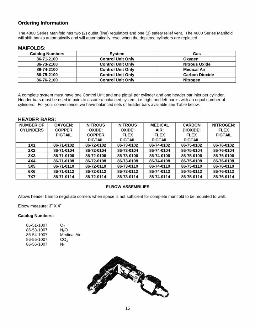
ELBOW ASSEMBLIES
Allows header bars to negotiate corners when space is not sufficient for complete manifold to be mounted to wall. Elbow measure: 3” X 4”
Catalog Numbers:
86-51-1007 O2 86-53-1007 N2O 86-54-1007 Medical Air 86-55-1007 CO2 86-56-1007 N2
15

Repair Parts List
Catalog No. Description Gas Qty. Per Kit
86-90-3041 High Pressure Relief Valve All 1
86-90-3042 Line Pressure Relief Valve Nitrous Oxide, Carbon Dioxide, Medical Air & Oxygen 1
86-90-3043 Line Pressure Relief Valve Nitrogen 1
86-90-3001 High Pressure Hand Valve Oxygen 1
86-90-3002 High Pressure Hand Valve Nitrous Oxide 1
86-90-3003 High Pressure Hand Valve Medical Air 1
86-90-3004 High Pressure Hand Valve Carbon Dioxide 1
86-90-3005 High Pressure Hand Valve Nitrogen 1
86-90-3044 0-5000 PSI Back Mount Gauge All 1
86-90-3045 0-100 PSI Back Mount Gauge All Except Nitrogen 1
86-90-3046 0-300 PSI Back Mount Gauge Nitrogen 1
86-90-3047 0-600 PSI Back Mount Gauge All 1
86-90-3048 Solenoid All 1
86-90-3014 High Pressure Regulator All 1
86-90-3027 Line Pressure Regulator All Except Nitrogen 1
86-90-3029 Line Pressure Regulator Nitrogen 1
86-90-3049 Check Valve Complete All 1
86-90-3026 3-Way Ball Valve Complete All 1
86-90-3050 Diaphragm All 1
86-90-3051 PCB, Electronic Circuit Board All 1
86-90-3052 Power supply All 1
86-90-3053 On/Off switch All 1
86-90-3054 Fuse Holder All 1
86-90-3055 Fuse, 3 Amp All 1
86-90-3057 Wire Harness, Power Supply All 1
86-90-3058 0-3000 PSI, Pressure Transducer All 1
86-90-3059 Thermostat Nitrous Oxide, Carbon Dioxide 1
86-90-3060 Heater Assy. w/ extra spade connector Nitrous Oxide, Carbon Dioxide 1
86-90-3061 Heater Assy. w/o extra spade connector Nitrous Oxide, Carbon Dioxide 1
86-90-3028 Line pressure regulator repair Kit All 1
86-90-3018 High pressure regulator repair Kit All 1
16

Trouble Shooting
This section is intended to serve as a general guide for identifying the potential functional problems which could occur in the operation of the manifold.
Only some minor checks and repairs are recommended to be made in the field.
Components removed from the manifold system for maintenance must be serviced, repaired and tested by properly qualified medical service personnel only. Original manufacturer’s parts, as supplied by Allied, must be used in the maintenance of manifolds.
Trouble Probable Cause Remedy or Check
0-5000 PSI Gauge not showing
pressure
Empty gas cylinders Replace empty tanks
Inlet valve closed Open inlet valve
Gauge failure Replace faulty gauge
Continuous flow of gas through vent
line exhaust. (Note: under normal
operation when the cylinders are replaced and bank is brought back on line a very small burp of gas will be vented outside)
Faulty High pressure relief valve Replace high pressure relief vale
Faulty Line pressure relief valve Replace line pressure relief valve
Faulty Solenoid Replace Solenoid
Pressure dropping simultaneously
through both cylinder banks (Note, an
alarm will be indicated by both green
LEDs being lit, one flashing and one
on continuously)
Pneumatic membrane seal not seated. Gas flowing through both sides of membrane.
The green LED which stays on continuously indicates the primary side. The blinking green LED is the reserve side. Close the reserve bank inlet valve and wait approximately 30 minutes until the membrane seal is made. Then open the reserve side inlet valve. The yellow LED, on the reserve side should turn on indicating normal manifold operation.
Diaphragm failure in Pneumatic switch
Replace Diaphragm
Solenoid Failure Replace Solenoid
Check valve Failure Replace check valve
LED’s don’t light On/Off switch turned Off Turn switch to on position
Fuse failure Replace fuse
Loose wire connection Tighten wire connection
No power in. Measure power in to be 115 VAC
Power supply failure Measure power supply output to be 15VDC
PCB failure Replace PCB
17

Trouble Probable Cause Remedy or Check
Leaking High pressure Regulator Loose Regulator cap Tighten cap
Regulator Diaphragm Leaks Replace Diaphragm
Leaking Low pressure Regulator Loose Regulator cap Tighten cap
Regulator Diaphragm leaks Replace Diaphragm
Low Gas Flow Filter upstream of high pressure regulator blocked
Remove inlet valve, inspect and clean filter.
Filter upstream of pneumatic switch blocked
Remove 90° elbow on upstream side of pneumatic switch, inspect and clean filter.
Inlet valve to Manifold not fully open. Cylinder valves not fully opened.
Open all inlet and cylinder valves on faulty side of manifold
Heaters on N2O or C02 manifold not
working.
Loose wiring Tighten Wiring/ Connector
Reset button on thermostat is tripped
Push red button on thermostat to reset.
18

LIMITED WARRANTY: Allied warrants for a period of one year from date of shipment that the products
manufactured by Allied are free from defects in material and workmanship. Allied makes no warranty with
respect to products manufactured by others and furnished hereunder, provided, however, Allied shall extend
to Buyer any warranties, which it received, from such vendors. Items found to be defective will be covered
under the warranty. The warranty will cover only the repair parts to correct the defective component.
In the event of breach of any warranty hereunder, Allied’s sole and exclusive liability shall be its option either
to repair or replace F.O.B. destination any defective products, or to accept return of such product and refund
the purchase price; in either case provided that written notice of such defect is given to Allied within warranty
period of product purchased, that the product is found by Allied to have been defective at the time of such
shipment, that the product has been installed and/or operated in accordance with Allied’s instructions, that no
repairs, alterations or replacements have been made by others without Allied’s written approval, and that
Buyer notifies Allied in writing within forty-five (45) days after the defect becomes apparent and promptly
furnishes full particulars in connection therewith, and provided further that in no event shall the aggregate
liability of Allied in connection with breach of any warranty or warranties exceed the purchase price paid for the
product purchased hereunder. Allied may, at its option, require the return of any product, transportation and
duties prepaid, to establish any claim of defect made by Buyer. Allied will not accept and shall have no
responsibility for products returned without its prior written consent and Allied will not assume any expense or
liability for repairs to products. In the event Allied elects to replace a defective product, costs of installation,
labor, service and all other costs to replace the product shall be the responsibility of Buyer. EXCEPT AS
EXPRESSLY STATED HEREIN, ALLIED MAKES NO WARRANTIES, EXPRESSED OR IMPLIED, AND
DOES NOT WARRANT THAT THE PRODUCTS ARE MERCHANTABLE OR FIT ANY PARTICULAR
PURPOSE.
Allied shall not, except as set forth above, be otherwise liable to Buyer or to any person who shall purchase
from Buyer, or use, any product supplied hereunder for damages of any kind, including, but not limited to
direct, indirect, special or consequential damages or loss of production or loss of profits resulting from any
cause whatsoever, including, but not limited to, any delay, act, error or omission of Allied.
Every claim from any cause shall be deemed waived by Buyer unless made, in writing, within twelve (12)
months of the receipt by Buyer of the goods to which such claim relates. No legal proceedings will be brought
for any breach of this contract more than one year after the accrual of the cause of action.