Embed Size (px)
Citation preview
PLASTICS TECHNOLOGY
INJECTION MOLDING TECHNOLOGY
HM Multicomponent
HM MULTICOMPONENT400 kN–2700 kNHM MULTICOMPONENT
400 kN–2700 kN clamping force
Battenfeld Injection Molding Machines HM Multicomponent Series 400 kN – 2700 kN
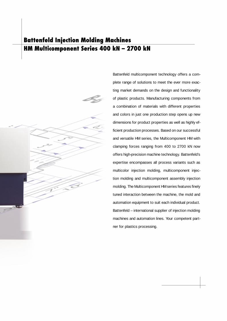
Battenfeld multicomponent technology offers a com-
plete range of solutions to meet the ever more exac-
ting market demands on the design and functionality
of plastic products. Manufacturing components from
a combination of materials with different properties
and colors in just one production step opens up new
dimensions for product properties as well as highly ef-
fi cient production processes. Based on our successful
and versatile HM series, the Multicomponent HM with
clamping forces ranging from 400 to 2700 kN now
offers high-precision machine technology. Battenfeld’s
expertise encompasses all process variants such as
multicolor injection molding, multicomponent injec-
tion molding and multicomponent assembly injection
molding. The Multicomponent HM series features fi nely
tuned interaction between the machine, the mold and
automation equipment to suit each individual product.
Battenfeld – international supplier of injection molding
machines and automation lines. Your competent part-
ner for plastics processing.
4
Special Features and Advantages of the Multicomponent HM
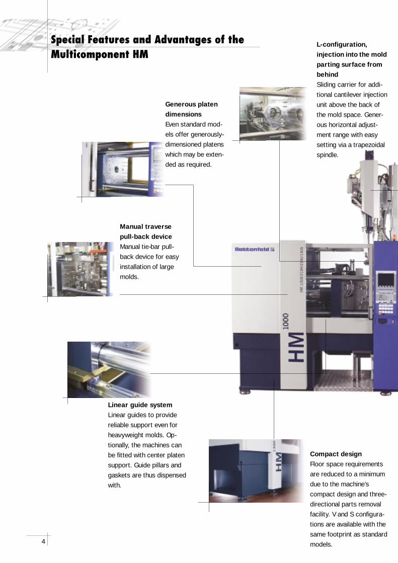
Generous platen dimensionsEven standard mod-els offer generously- dimensioned platens which may be exten-ded as required.
Compact designFloor space requirements are reduced to a minimum due to the machine’s compact design and three-directional parts removal facility. V and S confi gura-tions are available with the same footprint as standard models.
Linear guide system Linear guides to provide reliable support even forheavyweight molds. Op-tionally, the machines can be fi tted with center platen support. Guide pillars and gaskets are thus dispensed with.
L-configuration, injection into the mold parting surface from behindSliding carrier for addi-tional cantilever injection unit above the back of the mold space. Gener-ous horizontal adjust-ment range with easy setting via a trapezoidal spindle.
Manual traverse pull-back deviceManual tie-bar pull-back device for easy installation of large molds.
5
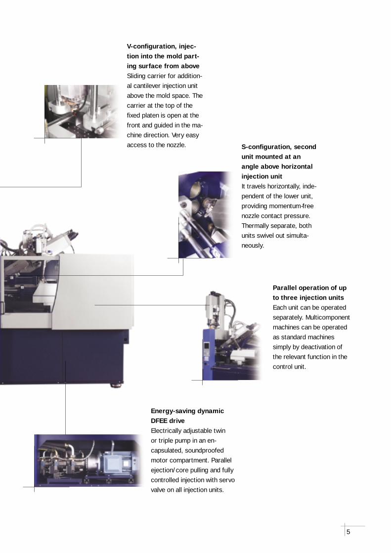
Energy-saving dynamic DFEE drive Electrically adjustable twin or triple pump in an en-capsulated, soundproofed motor compartment. Parallel ejection/core pulling and fully controlled injection with servo valve on all injection units.
Parallel operation of up to three injection units Each unit can be operated separately. Multicomponent machines can be operated as standard machines simply by deactivation of the relevant function in the control unit.
V-confi guration, injec-tion into the mold part-ing surface from aboveSliding carrier for addition-al cantilever injection unit above the mold space. The carrier at the top of the fi xed platen is open at the front and guided in the ma-chine direction. Very easy access to the nozzle. S-confi guration, second
unit mounted at an angle above horizontal injection unit It travels horizontally, inde-pendent of the lower unit, providing momentum-free nozzle contact pressure. Thermally separate, both units swivel out simulta-neously.
6
Multicomponent TechnologyVersatility to Suit Every Application
Multicolor and multi-component injection molding processes (assembly technique, hard-soft combination) can be carried out with injection units in optional V, L or S confi guration which are combined with the most suitable compo-nent transfer technique (rotary plate, indexing plate, transfer molding or slide-cam technique).
Battenfeld has a solution for all pro-cessing techniques
Hard-soft combina-tions
The use of thermoplastic elastomers allows direct overmolding of gaskets onto components. The choice of soft materials improves the tactile properties of fi nished parts. For such applica-tions, a combination of materials with adhesive properties is a prere-quisite. The bonding strength can be impro-ved by mechanical an-choring. Multicomponent technology is also a popular technique for LIM applications.
Multicomponent assembly injection molding
Components with hinged attachments can be produced in one step. This requires a selection of raw materials without adhesive properties for easy production of ball joints and hinges.
the best material combi-nation, as shown in the charts below, and the attainable bond strength, are also crucial factors. The bond strength is signifi cantly infl uenced by the injection sequence of the component materi-als. Processors can draw on Battenfeld’s extensive experience in multicom-
The choice of the ap-propriate machine and related processes is de-termined by factors such as effi ciency, automation and cycle times. Normal-ly, all components are injected simultaneously to minimize cycle times. Staggered injection to avoid unnecessary strain on the mold is also a consideration. Apart from the right choice of machinery and mold technology,
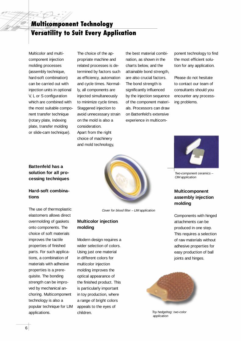
Multicolor injection molding
Modern design requires a wider selection of colors. Using just one material in different colors for multicolor injection molding improves the optical appearance of the fi nished product. This is particularly important in toy production, where a range of bright colors appeals to the eyes of children.
ponent technology to fi nd the most effi cient solu-tion for any application.
Please do not hesitate to contact our team of consultants should you encounter any process-ing problems.
Cover for blood fi lter – LIM application
Toy hedgehog: two-color application
Two-component ceramics – CIM application
7
TPE-polyamide-
bases
TPE-polyester-elastomers
TPE-polyolefi n-
bases
TPE-styrene-
bases
TPE-thermo-plastic
polyurethanes
TPE-adhesion-modifi edgrades
ABS ! " ! ! ! "
ASA ! !
CA !
PA 6 " ! ! ! "
PA 6.6 " ! ! "
PA-Blend " " " "
PBTP ! " ! ! "
PC ! " ! " ! "
PC/ABS ! " ! " ! "
PC/PBT ! " ! " ! "
PC/PET ! " ! " ! "
PE ! " " !
PETP ! !
PMMA " " !
POM ! ! !
PP ! ! ! "
PPO ! !
PS ! ! ! "
SAN ! ! "
AB
S
ASA CA
PA 6
PA 6
.6
PA-B
lend
PB
TP
PC
PC
/AB
S
PC
/PB
T
PC
/PET
PE
PET
P
PM
MA
PO
M
PP
PP
O
PS
SAN
TPE/
TPU
ABS " ! ! ! ! ! ! ! ! ! " ! ! ! ! " "
ASA ! " ! ! ! ! ! ! ! ! ! ! ! ! ! ! ! "
CA ! ! " ! ! ! ! !
PA 6 ! " " ! ! " ! ! ! " ! " ! ! "
PA 6.6 ! ! " " ! " ! ! ! " ! " ! ! "
PA-Blend ! ! " " " ! "
PBTP ! ! ! ! " " ! ! ! ! " ! " " " " ! "
PC ! ! ! ! " ! ! ! ! ! " ! ! ! "
PC/ABS ! ! ! ! ! ! " ! ! " ! ! "
PC/PBT ! ! ! ! ! ! ! " ! ! ! ! " ! ! "
PC/PET ! ! ! ! ! ! ! ! " ! ! ! " ! ! "
PE " ! ! " " " " ! " !
PETP ! ! ! ! ! ! ! " "
PMMA ! ! " ! ! ! " ! ! ! ! "
POM " ! ! ! ! " " " " " " ! " "
PP ! ! " " " " ! ! ! ! ! ! " "
PPO ! ! ! ! ! ! ! " " "
PS ! ! ! ! " ! ! ! ! ! ! " "
SAN " ! ! ! ! " " " " ! ! " " !
TPE/TPU " " " " " " " " " " ! " " " " " " ! "
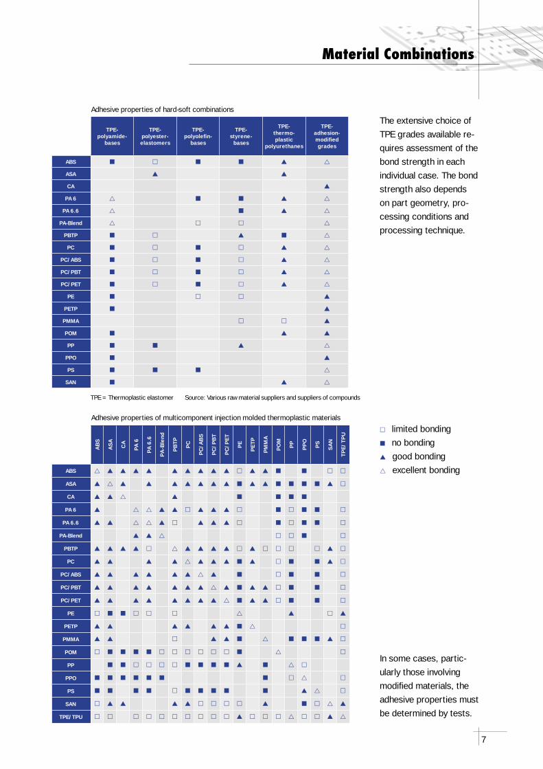
" limited bonding! no bonding! good bonding" excellent bonding
Material Combinations
Adhesive properties of multicomponent injection molded thermoplastic materials
Adhesive properties of hard-soft combinations
The extensive choice of TPE grades available re-quires assessment of the bond strength in each individual case. The bond strength also depends on part geometry, pro-cessing conditions and processing technique.
In some cases, partic-ularly those involving modifi ed materials, the adhesive properties must be determined by tests.
TPE = Thermoplastic elastomer Source: Various raw material suppliers and suppliers of compounds
8
Confi guration of the Injection Units
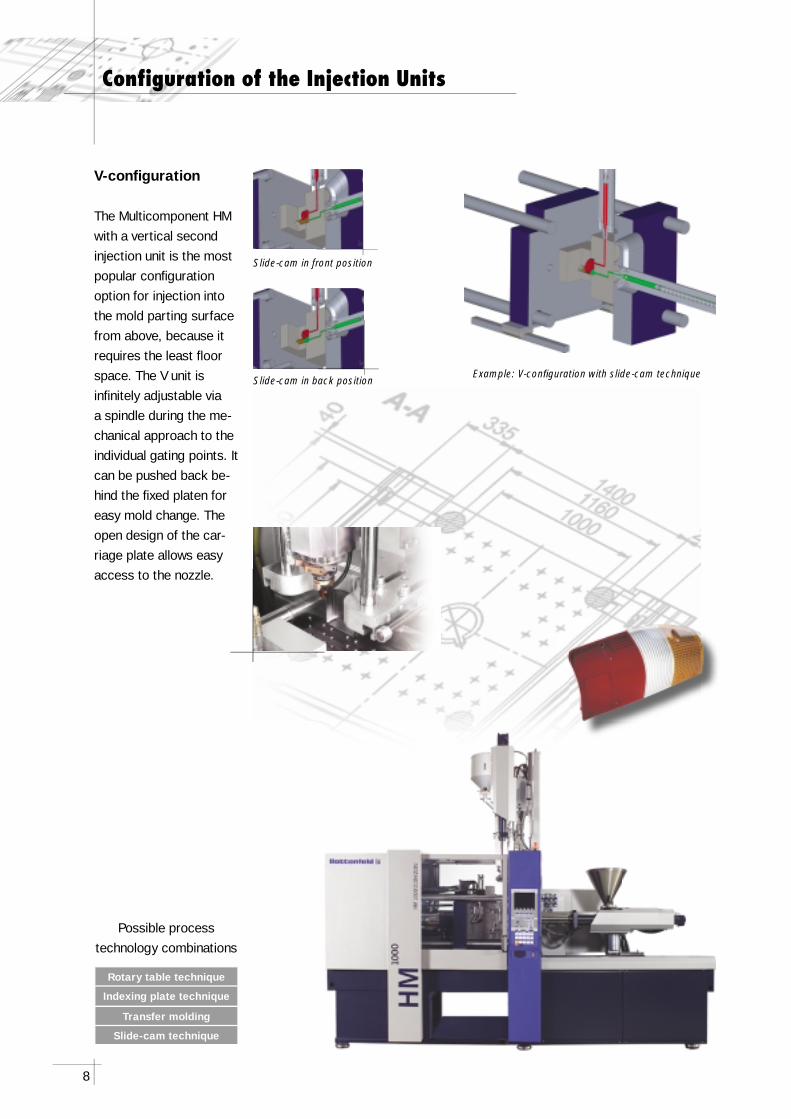
V-confi guration
The Multicomponent HM with a vertical second injection unit is the most popular confi guration option for injection into the mold parting surface from above, because it requires the least fl oor space. The V unit is infi nitely adjustable via a spindle during the me-chanical approach to the individual gating points. It can be pushed back be-hind the fi xed platen for easy mold change. The open design of the car-riage plate allows easy access to the nozzle.
Rotary table technique
Indexing plate technique
Transfer molding
Slide-cam technique
Example: V-confi guration with slide-cam technique
Possible process technology combinations
Slide-cam in front position
Slide-cam in back position
9
Rotary table technique
Indexing plate technique
Transfer molding
Slide-cam technique
Possible process technology combinations
Confi guration of the Injection Units
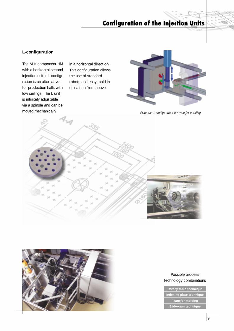
L-confi guration
The Multicomponent HM with a horizontal second injection unit in L-confi gu-ration is an alternative for production halls with low ceilings. The L unit is infi nitely adjustable via a spindle and can be moved mechanically
in a horizontal direction. This confi guration allows the use of standard robots and easy mold in-stalla-tion from above.
Example: L-confi guration for transfer molding
10
Rotary table technique
Indexing plate technique
Transfer molding
Slide-cam technique
Possible process technology combinations
Confi guration of the Injection Units
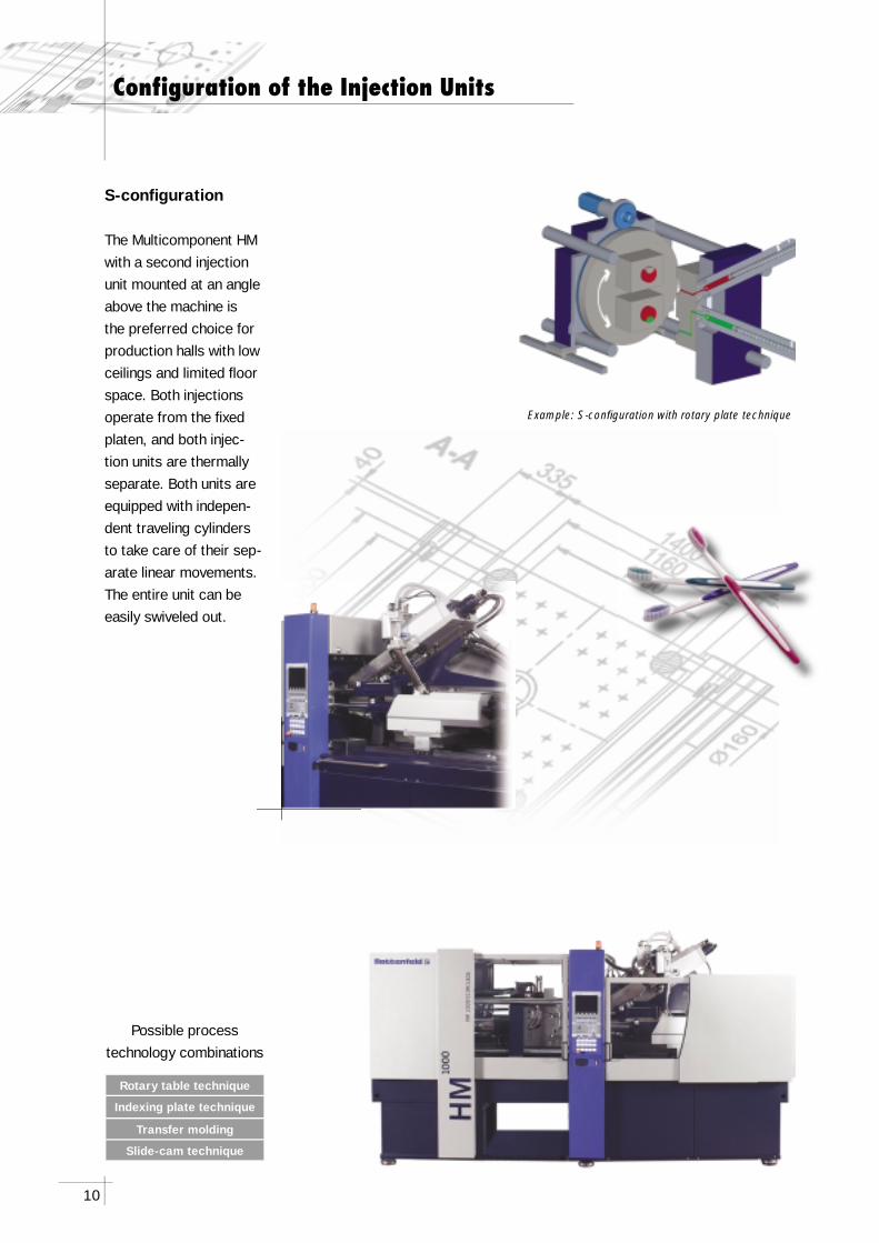
S-confi guration
The Multicomponent HM with a second injection unit mounted at an angle above the machine is the preferred choice for production halls with low ceilings and limited fl oor space. Both injections operate from the fi xed platen, and both injec-tion units are thermally separate. Both units are equipped with indepen-dent traveling cylinders to take care of their sep-arate linear movements. The entire unit can be easily swiveled out.
Example: S-confi guration with rotary plate technique
11
Rotary table technique
Indexing plate technique
Transfer molding
Slide-cam technique
Possible process technology combinations
Confi guration of the Injection Units
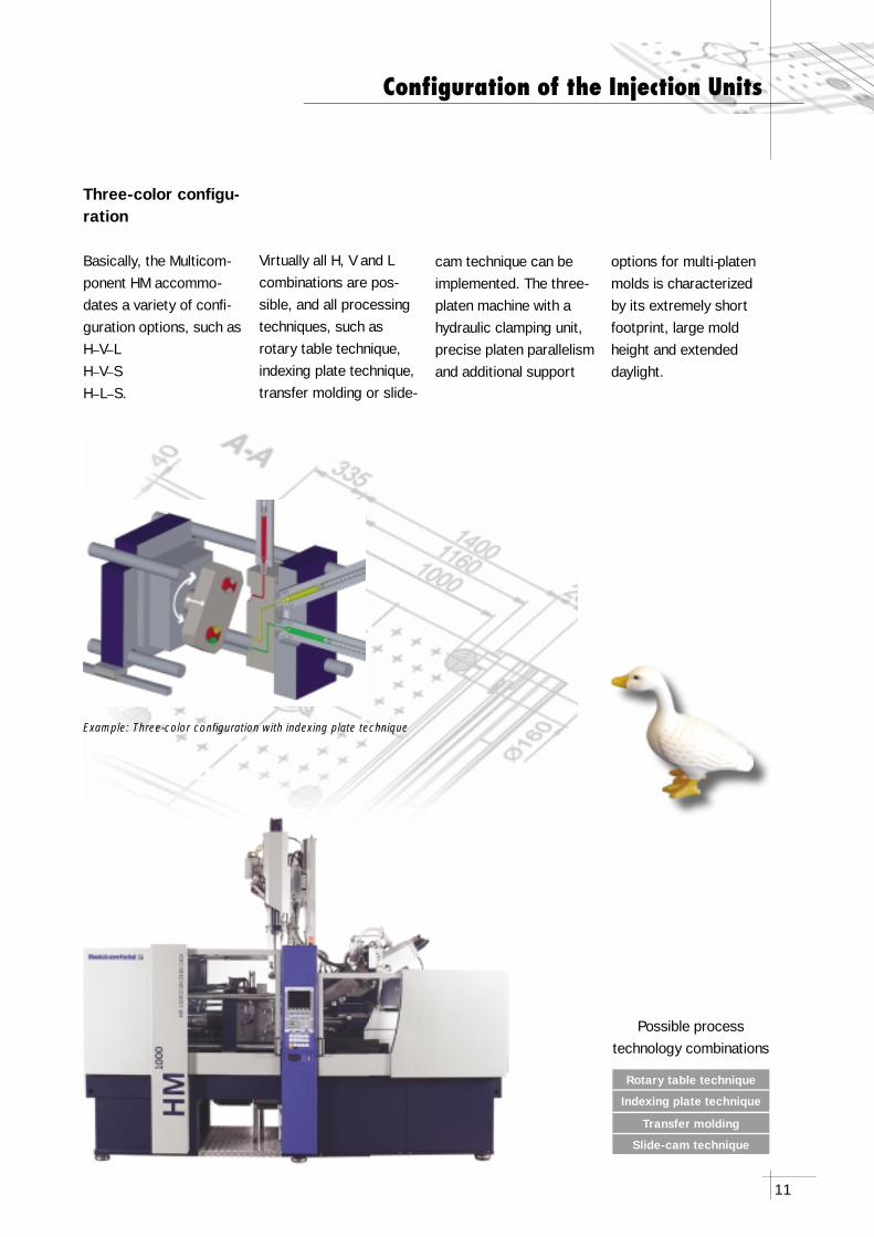
Three-color confi gu-ration
Basically, the Multicom-ponent HM accommo-dates a variety of confi -guration options, such asH–V–LH–V–SH–L–S.
cam technique can be implemented. The three-platen machine with a hydraulic clamping unit, precise platen parallelism and additional support
Virtually all H, V and L combinations are pos-sible, and all processing techniques, such as rotary table technique, indexing plate technique, transfer molding or slide-
options for multi-platen molds is characterized by its extremely short footprint, large mold height and extended daylight.
Example: Three-color confi guration with indexing plate technique
12
Processing Techniques
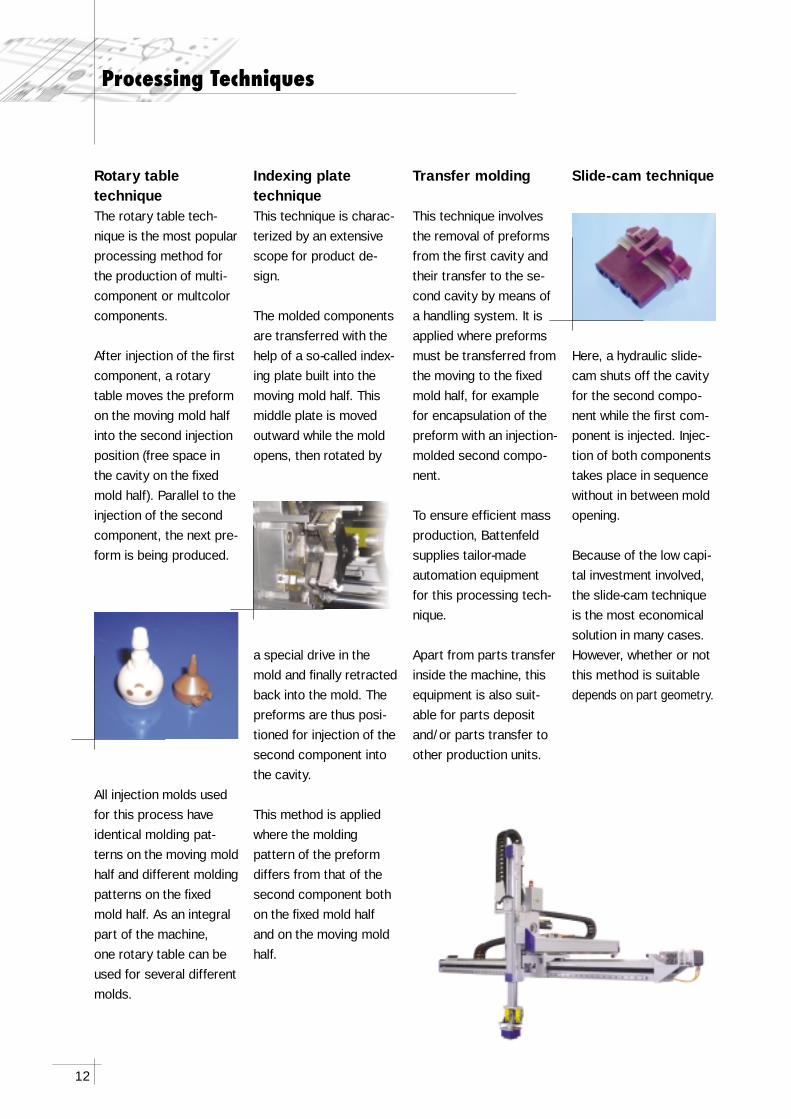
Indexing plate techniqueThis technique is charac-terized by an extensive scope for product de-sign.
The molded components are transferred with the help of a so-called index-ing plate built into the moving mold half. This middle plate is moved outward while the mold opens, then rotated by
a special drive in the mold and fi nally retracted back into the mold. The preforms are thus posi-tioned for injection of the second component into the cavity.
This method is applied where the molding pattern of the preform differs from that of the second component both on the fi xed mold half and on the moving mold half.
Rotary table techniqueThe rotary table tech-nique is the most popular processing method for the production of multi-component or multcolor components.
After injection of the fi rst component, a rotary table moves the preform on the moving mold half into the second injection position (free space in the cavity on the fi xed mold half). Parallel to the injection of the second component, the next pre-form is being produced.
All injection molds used for this process have identical molding pat-terns on the moving mold half and different molding patterns on the fi xed mold half. As an integral part of the machine, one rotary table can be used for several different molds.
Slide-cam technique
Here, a hydraulic slide- cam shuts off the cavity for the second compo-nent while the fi rst com-ponent is injected. Injec-tion of both components takes place in sequence without in between mold opening.
Because of the low capi-tal investment involved, the slide-cam technique is the most economical solution in many cases. However, whether or not this method is suitable depends on part geometry.
Transfer molding
This technique involves the removal of preforms from the fi rst cavity and their transfer to the se-cond cavity by means of a handling system. It is applied where preforms must be transferred from the moving to the fi xed mold half, for example for encapsulation of the preform with an injection-molded second compo-nent.
To ensure effi cient mass production, Battenfeld supplies tailor-made automation equipment for this processing tech-nique.
Apart from parts transfer inside the machine, this equipment is also suit-able for parts deposit and/or parts transfer to other production units.
13
1 2
34
4 3
1 2
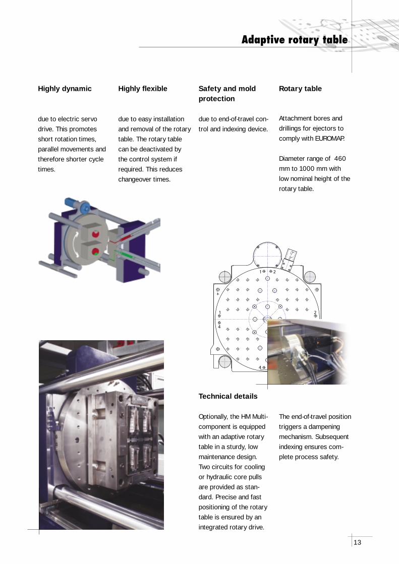
Technical details
Optionally, the HM Multi-component is equipped with an adaptive rotary table in a sturdy, low maintenance design. Two circuits for cooling or hydraulic core pulls are provided as stan-dard. Precise and fast positioning of the rotary table is ensured by an integrated rotary drive.
Highly dynamic
due to electric servodrive. This promotes short rotation times, parallel movements and therefore shorter cycle times.
Highly fl exible
due to easy installation and removal of the rotary table. The rotary table can be deactivated by the control system if required. This reduces changeover times.
Safety and mold protection
due to end-of-travel con-trol and indexing device.
Rotary table
Attachment bores and drillings for ejectors to comply with EUROMAP.
Diameter range of 460 mm to 1000 mm with low nominal height of the rotary table.
Adaptive rotary table
The end-of-travel position triggers a dampening mechanism. Subsequent indexing ensures com-plete process safety.
14
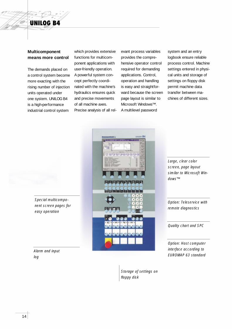
Alarm and input log
Storage of settings on fl oppy disk
Large, clear color screen, page layout similar to Microsoft Win-dows™
Option: Teleservice with remote diagnostics
Quality chart and SPC
Option: Host computer interface according to EUROMAP 63 standard
Special multicompo-nent screen pages for easy operation
UNILOG B4
Multicomponent means more control
The demands placed on a control system become more exacting with the rising number of injection units operated under one system. UNILOG B4 is a high-performance industrial control system
which provides extensive functions for multicom-ponent applications with user-friendly operation.A powerful system con-cept perfectly coordi-nated with the machine’s hydraulics ensures quick and precise movements of all machine axes. Precise analysis of all rel-
evant process variables provides the compre-hensive operator control required for demanding applications. Control, operation and handling is easy and straightfor-ward because the screen page layout is similar to Microsoft Windows™. A multilevel password
system and an entry logbook ensure reliable process control. Machine settings entered in physi-cal units and storage of settings on fl oppy disk permit machine data transfer between ma-chines of different sizes.
15
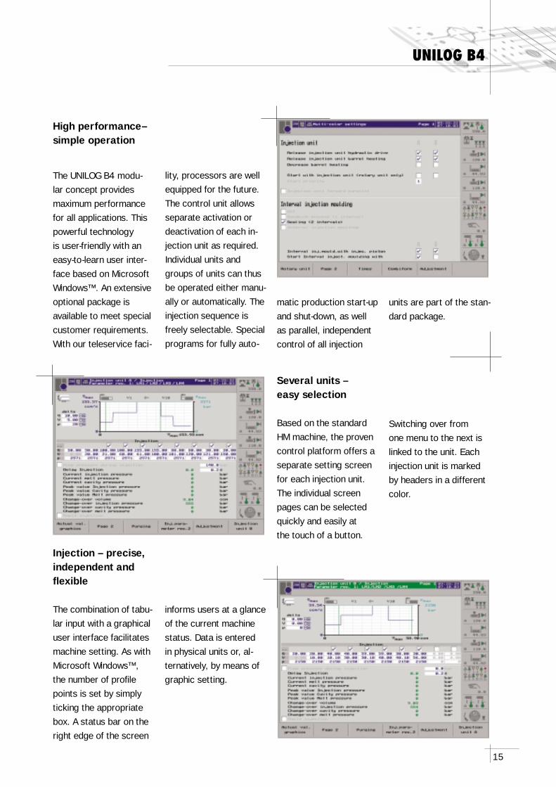
Several units – easy selection
Based on the standard HM machine, the proven control platform offers a separate setting screen for each injection unit. The individual screen pages can be selected quickly and easily at the touch of a button.
Injection – precise, independent and fl exible
The combination of tabu-lar input with a graphical user interface facilitates machine setting. As with Microsoft Windows™, the number of profi le points is set by simply ticking the appropriate box. A status bar on the right edge of the screen
UNILOG B4
Switching over from one menu to the next is linked to the unit. Each injection unit is marked by headers in a different color.
informs users at a glance of the current machine status. Data is entered in physical units or, al-ternatively, by means of graphic setting.
High performance– simple operation
The UNILOG B4 modu-lar concept provides maximum performance for all applications. This powerful technology is user-friendly with an easy-to-learn user inter-face based on Microsoft Windows™. An extensive optional package is available to meet special customer requirements. With our teleservice faci-
lity, processors are well equipped for the future. The control unit allows separate activation or deactivation of each in-jection unit as required. Individual units and groups of units can thus be operated either manu-ally or automatically. The injection sequence is freely selectable. Special programs for fully auto-
matic production start-up and shut-down, as well as parallel, independent control of all injection
units are part of the stan-dard package.
16
UNILOG B4
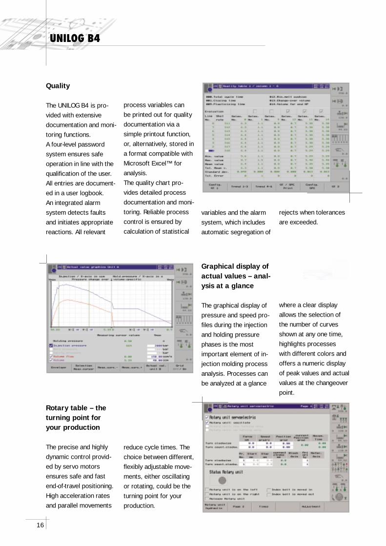
Quality
The UNILOG B4 is pro-vided with extensive documentation and moni-toring functions. A four-level password system ensures safe operation in line with the qualifi cation of the user. All entries are document-ed in a user logbook. An integrated alarm system detects faults and initiates appropriate reactions. All relevant
Graphical display of actual values – anal-ysis at a glance
The graphical display of pressure and speed pro-fi les during the injection and holding pressure phases is the most important element of in-jection molding process analysis. Processes can be analyzed at a glance
Rotary table – the turning point for your production
The precise and highly dynamic control provid-ed by servo motors ensures safe and fast end-of-travel positioning. High acceleration rates and parallel movements
process variables can be printed out for quality documentation via a simple printout function, or, alternatively, stored in a format compatible with Microsoft Excel™ for analysis.The quality chart pro-vides detailed process documentation and moni-toring. Reliable process control is ensured by calculation of statistical
variables and the alarm system, which includes automatic segregation of
rejects when tolerances are exceeded.
where a clear display allows the selection of the number of curves shown at any one time, highlights processes with different colors and offers a numeric display of peak values and actual values at the changeover point.
reduce cycle times. The choice between different, fl exibly adjustable move-ments, either oscillating or rotating, could be the turning point for your production.
17
UNILOG B4
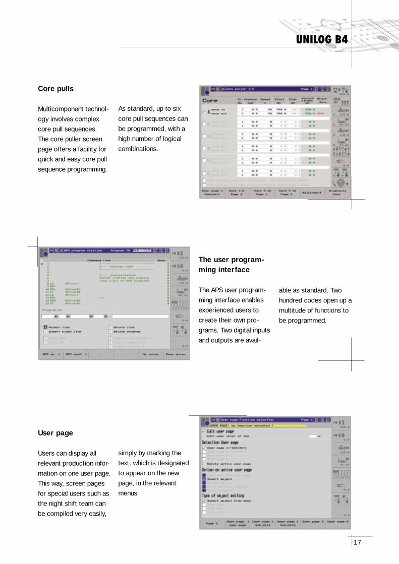
Core pulls
Multicomponent technol-ogy involves complex core pull sequences. The core puller screen page offers a facility for quick and easy core pull sequence programming.
The user program-ming interface
The APS user program-ming interface enables experienced users to create their own pro-grams. Two digital inputs and outputs are avail-
User page
Users can display all relevant production infor-mation on one user page. This way, screen pages for special users such as the night shift team can be compiled very easily,
As standard, up to six core pull sequences can be programmed, with a high number of logical combinations.
able as standard. Two hundred codes open up a multitude of functions to be programmed.
simply by marking the text, which is designated to appear on the new page, in the relevant menus.
18
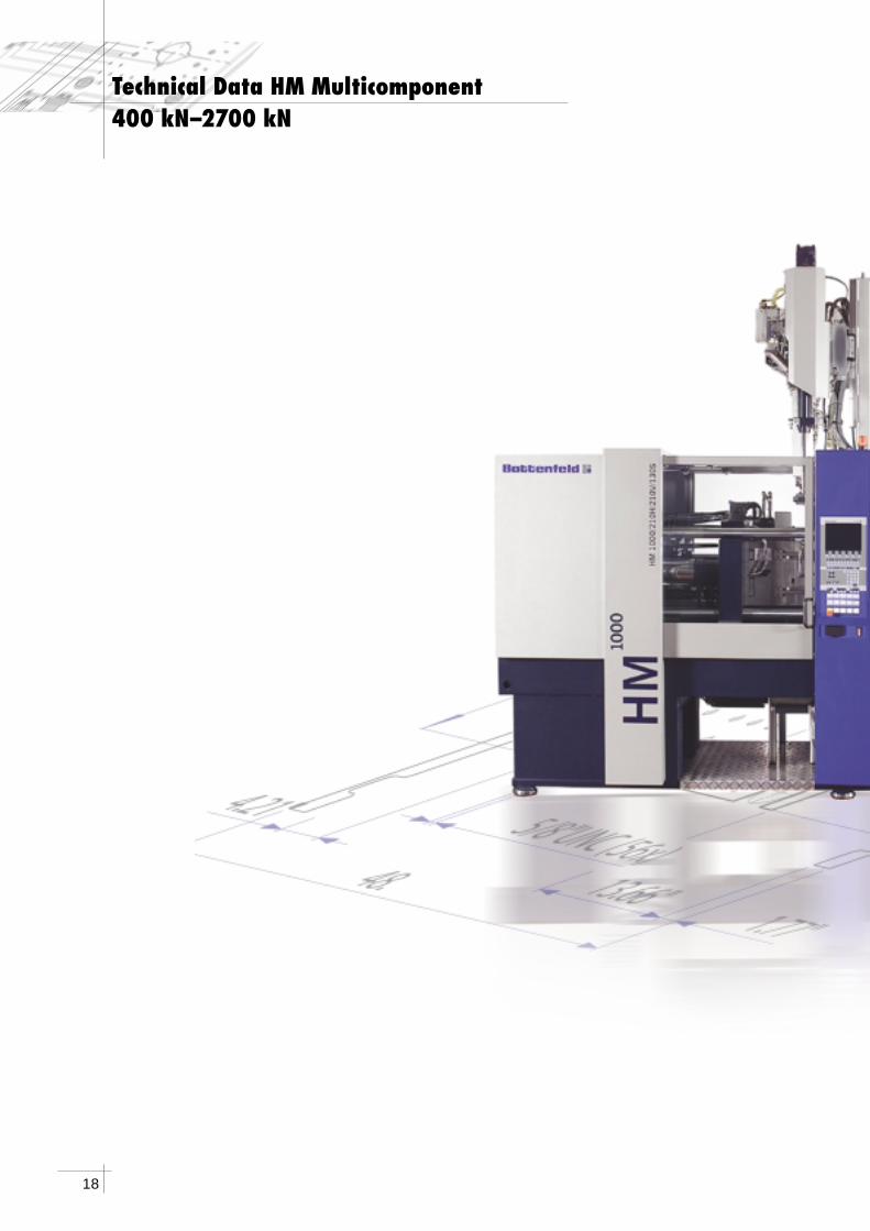
Technical Data HM Multicomponent400 kN–2700 kN
19
20
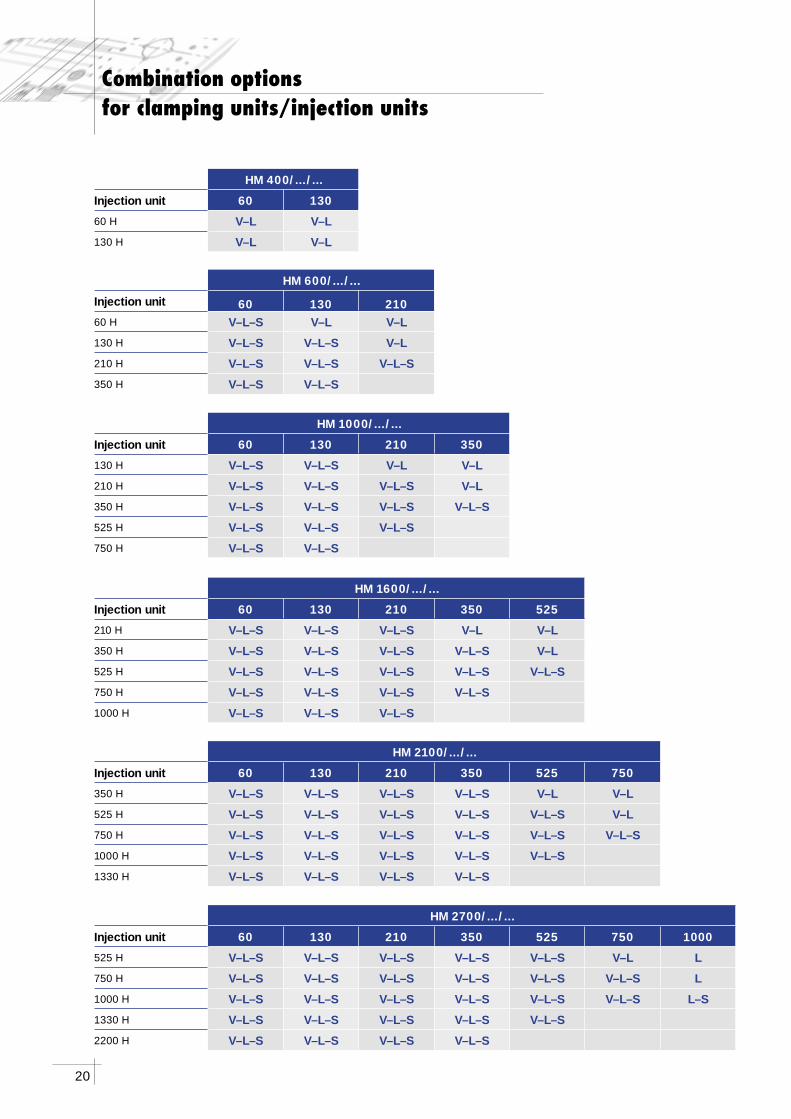
HM 1600/.../...
Injection unit 60 130 210 350 525
210 H V–L–S V–L–S V–L–S V–L V–L
350 H V–L–S V–L–S V–L–S V–L–S V–L
525 H V–L–S V–L–S V–L–S V–L–S V–L–S
750 H V–L–S V–L–S V–L–S V–L–S
1000 H V–L–S V–L–S V–L–S
HM 1000/.../...
Injection unit 60 130 210 350
130 H V–L–S V–L–S V–L V–L
210 H V–L–S V–L–S V–L–S V–L
350 H V–L–S V–L–S V–L–S V–L–S
525 H V–L–S V–L–S V–L–S
750 H V–L–S V–L–S
HM 600/.../...
Injection unit 60 130 21060 H V–L–S V–L V–L
130 H V–L–S V–L–S V–L
210 H V–L–S V–L–S V–L–S
350 H V–L–S V–L–S
HM 400/.../...
Injection unit 60 130
60 H V–L V–L
130 H V–L V–L
Combination options for clamping units/injection units
HM 2100/.../...
Injection unit 60 130 210 350 525 750
350 H V–L–S V–L–S V–L–S V–L–S V–L V–L
525 H V–L–S V–L–S V–L–S V–L–S V–L–S V–L
750 H V–L–S V–L–S V–L–S V–L–S V–L–S V–L–S
1000 H V–L–S V–L–S V–L–S V–L–S V–L–S
1330 H V–L–S V–L–S V–L–S V–L–S
HM 2700/.../...
Injection unit 60 130 210 350 525 750 1000
525 H V–L–S V–L–S V–L–S V–L–S V–L–S V–L L
750 H V–L–S V–L–S V–L–S V–L–S V–L–S V–L–S L
1000 H V–L–S V–L–S V–L–S V–L–S V–L–S V–L–S L–S
1330 H V–L–S V–L–S V–L–S V–L–S V–L–S
2200 H V–L–S V–L–S V–L–S V–L–S
21
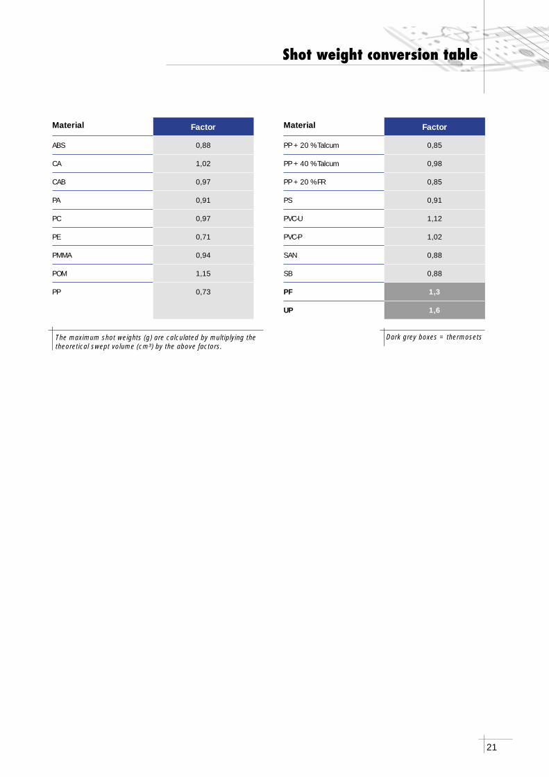
The maximum shot weights (g) are calculated by multiplying the theoretical swept volume (cm³) by the above factors.
Material Factor
ABS 0,88
CA 1,02
CAB 0,97
PA 0,91
PC 0,97
PE 0,71
PMMA 0,94
POM 1,15
PP 0,73
Material Factor
PP + 20 % Talcum 0,85
PP + 40 % Talcum 0,98
PP + 20 % FR 0,85
PS 0,91
PVC-U 1,12
PVC-P 1,02
SAN 0,88
SB 0,88
PF 1,3
UP 1,6
Dark grey boxes = thermosets
Shot weight conversion table
22
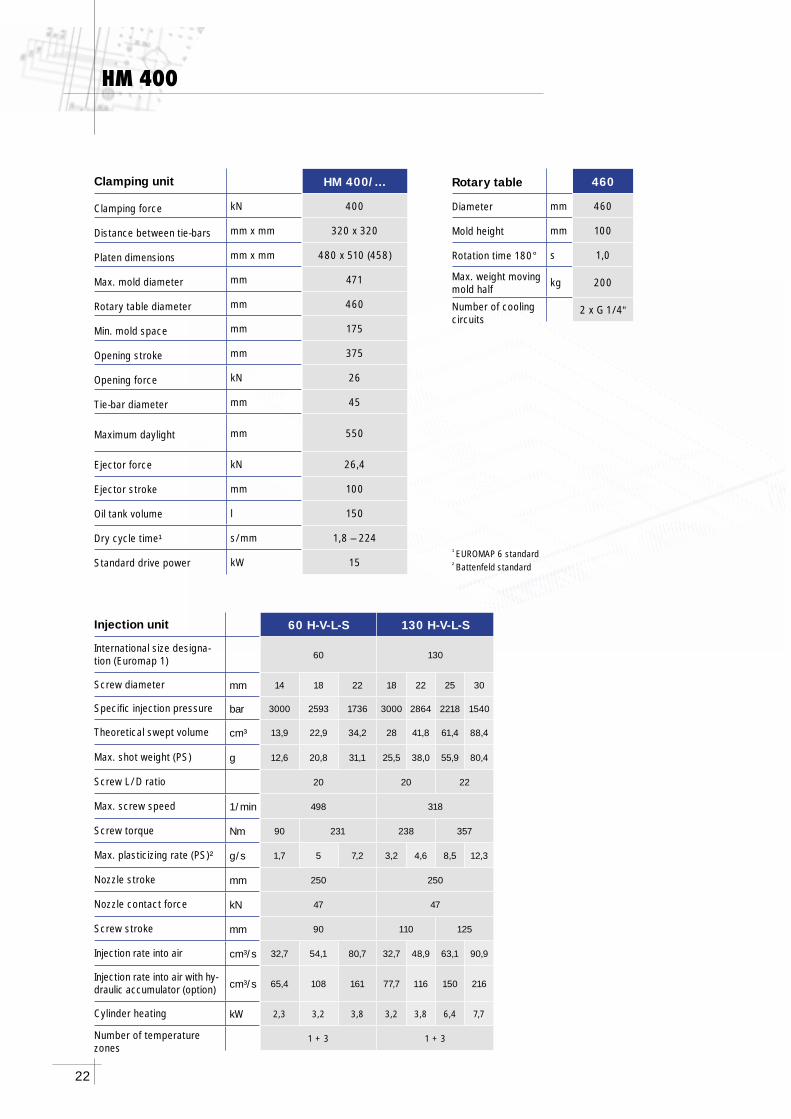
HM 400
60 H-V-L-S 130 H-V-L-S
60 130
mm 14 18 22 18 22 25 30
bar 3000 2593 1736 3000 2864 2218 1540
cm³ 13,9 22,9 34,2 28 41,8 61,4 88,4
g 12,6 20,8 31,1 25,5 38,0 55,9 80,4
20 20 22
1/min 498 318
Nm 90 231 238 357
g/s 1,7 5 7,2 3,2 4,6 8,5 12,3
mm 250 250
kN 47 47
mm 90 110 125
cm³/s 32,7 54,1 80,7 32,7 48,9 63,1 90,9
cm³/s 65,4 108 161 77,7 116 150 216
kW 2,3 3,2 3,8 3,2 3,8 6,4 7,7
1 + 3 1 + 3
HM 400/…
kN 400
mm x mm 320 x 320
mm x mm 480 x 510 (458)
mm 471
mm 460
mm 175
mm 375
kN 26
mm 45
mm 550
kN 26,4
mm 100
l 150
s/mm 1,8 – 224
kW 15
460
mm 460
mm 100
s 1,0
kg 200
2 x G 1/4“
¹ EUROMAP 6 standard² Battenfeld standard
Injection unit
International size designa-tion (Euromap 1)
Screw diameter
Specifi c injection pressure
Theoretical swept volume
Max. shot weight (PS)
Screw L/D ratio
Max. screw speed
Screw torque
Max. plasticizing rate (PS)²
Nozzle stroke
Nozzle contact force
Screw stroke
Injection rate into air
Injection rate into air with hy-draulic accumulator (option)
Cylinder heating
Number of temperature zones
Clamping unit
Clamping force
Distance between tie-bars
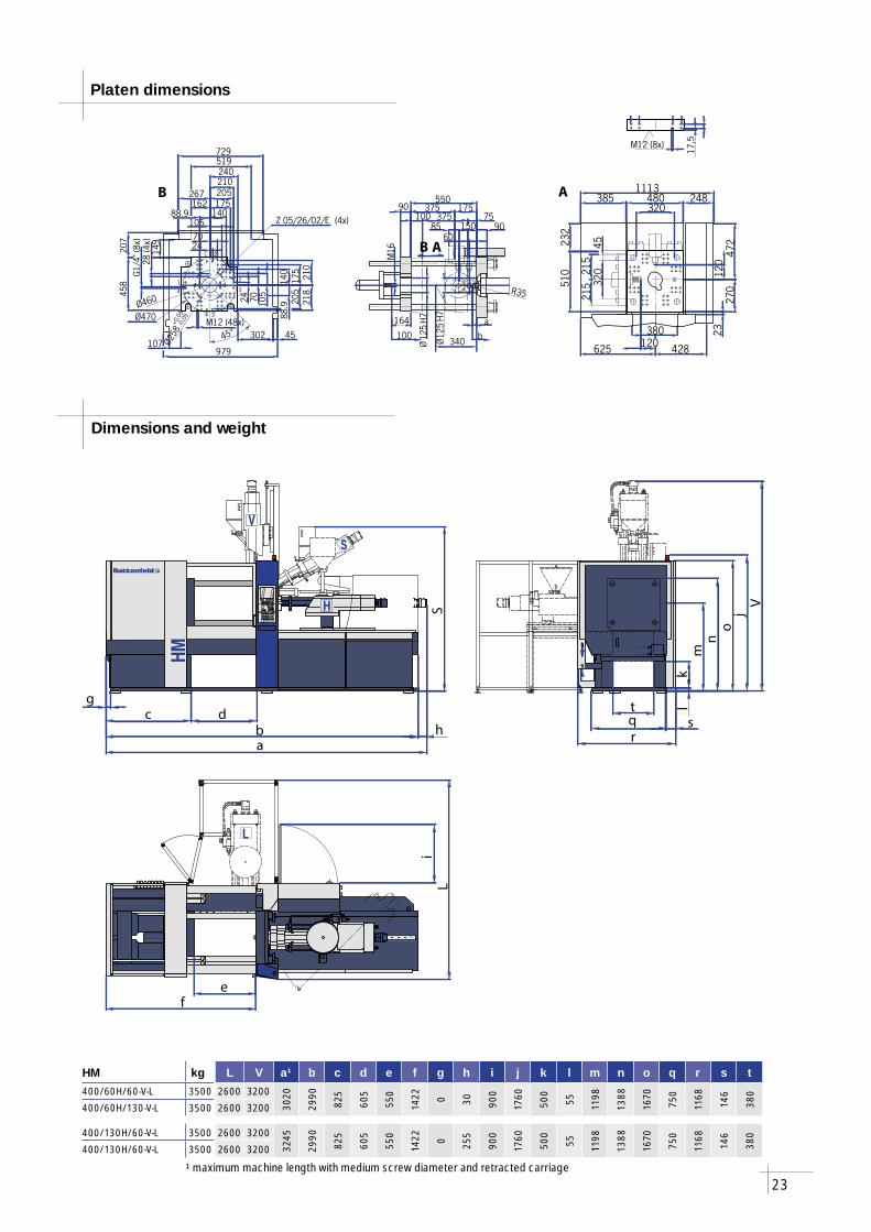
Platen dimensions
Max. mold diameter
Rotary table diameter
Min. mold space
Opening stroke
Opening force
Tie-bar diameter
Maximum daylight
Ejector force
Ejector stroke
Oil tank volume
Dry cycle time¹
Standard drive power
Rotary table
Diameter
Mold height
Rotation time 180°
Max. weight moving mold half
Number of cooling circuits
23
l
V
S
H
HM
L
fe
Li
c
a
S
bd
h
g
o
k
r
tq
lm
n
jV
s
Ø12
5H7
Ø12
5H7
175375
90
90550
M16
320480
1113248385
27032
0
510
472
625 428
M12 (8x)
45
100
164 a
b 380
232
23
17,5
340
6085 150
375100 75
Ø460
120
215
215
120
B A
B A
R35
70105
140175
210
107302 45
70 105
175
458
M12 (48x)
218
149
240
140 210
162267
519729
207
979
Ø470
1
4
2
3
2
4 3
2424 20
5
205
Z 05/26/02/E (4x)
Ø258
+0.0
5-0
.05
1
28(4
x)
88.9
88.9
G1/
4"(8
x)
45°
HM kg L V a¹ b c d e f g h i j k l m n o q r s t400/60H/60-V-L 3500 2600 3200
3020
2990
825
605
550
1422 0 30 900
1760
500
55 1198
1388
1670
750
1168
146
380
400/60H/130-V-L 3500 2600 3200
400/130H/60-V-L 3500 2600 3200
3245
2990
825
605
550
1422 0 255
900
1760
500
55 1198
1388
1670
750
1168
146
380
400/130H/60-V-L 3500 2600 3200
Platen dimensions
Dimensions and weight
¹ maximum machine length with medium screw diameter and retracted carriage
24
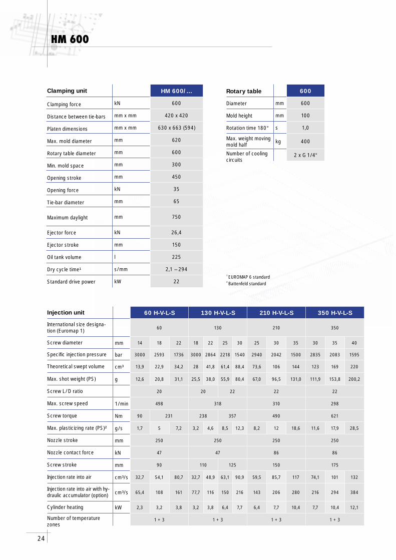
HM 600
60 H-V-L-S 130 H-V-L-S 210 H-V-L-S 350 H-V-L-S
60 130 210 350
mm 14 18 22 18 22 25 30 25 30 35 30 35 40
bar 3000 2593 1736 3000 2864 2218 1540 2940 2042 1500 2835 2083 1595
cm³ 13,9 22,9 34,2 28 41,8 61,4 88,4 73,6 106 144 123 169 220
g 12,6 20,8 31,1 25,5 38,0 55,9 80,4 67,0 96,5 131,0 111,9 153,8 200,2
20 20 22 22 22
1/min 498 318 310 298
Nm 90 231 238 357 490 621
g/s 1,7 5 7,2 3,2 4,6 8,5 12,3 8,2 12 18,6 11,6 17,9 28,5
mm 250 250 250 250
kN 47 47 86 86
mm 90 110 125 150 175
cm³/s 32,7 54,1 80,7 32,7 48,9 63,1 90,9 59,5 85,7 117 74,1 101 132
cm³/s 65,4 108 161 77,7 116 150 216 143 206 280 216 294 384
kW 2,3 3,2 3,8 3,2 3,8 6,4 7,7 6,4 7,7 10,4 7,7 10,4 12,1
1 + 3 1 + 3 1 + 3 1 + 3
HM 600/…
kN 600
mm x mm 420 x 420
mm x mm 630 x 663 (594)
mm 620
mm 600
mm 300
mm 450
kN 35
mm 65
mm 750
kN 26,4
mm 150
l 225
s/mm 2,1 – 294
kW 22
600
mm 600
mm 100
s 1,0
kg 400
2 x G 1/4“
¹ EUROMAP 6 standard² Battenfeld standard
Injection unit
International size designa-tion (Euromap 1)
Screw diameter
Specifi c injection pressure
Theoretical swept volume
Max. shot weight (PS)
Screw L/D ratio
Max. screw speed
Screw torque
Max. plasticizing rate (PS)²
Nozzle stroke
Nozzle contact force
Screw stroke
Injection rate into air
Injection rate into air with hy-draulic accumulator (option)
Cylinder heating
Number of temperature zones
Clamping unit
Clamping force
Distance between tie-bars
Platen dimensions
Max. mold diameter
Rotary table diameter
Min. mold space
Opening stroke
Opening force
Tie-bar diameter
Maximum daylight
Ejector force
Ejector stroke
Oil tank volume
Dry cycle time¹
Standard drive power
Rotary table
Diameter
Mold height
Rotation time 180°
Max. weight moving mold half
Number of cooling circuits
25
l
V
S
H
HM
L
fe
Li
c
a
S
bd
h
g
o
k
r
tq
lm
n
jV
s
70140175210
107 347 45
7014
0420
1307247430
420
678
729
34859
4
M16 (56x)
279
399
245
175
430
120300
450
120 750
M16
Ø12
5H7
245150 30
a
202342
644924
399
745 562
23
1174
210 12
5
R35
170
170365
60
17585
Ø12
5H7
520
260
260
630
245G1/
4"(8
x)
100 200
Ø600
490
7035M16 (8x)
280
450
41
1 2
23
4 3
65
24
24
275
275
Ø25
8+
0.05
- 0.0
5
Z 05/26/02/E (4x)
88.9
88.9
28(4
x) B A
B A
Ø620
45°
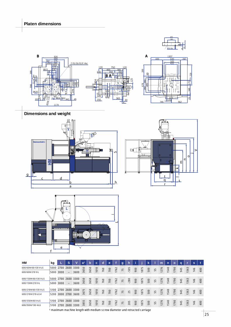
HM kg L S V a¹ b c d e f g h i j k l m n o q r s t600/60H/60-130 V-L-S 5000 2700 2600 3300
3650
3650
1010
760
700
1762 75 - 505
900
1875
500
55 1276
1540
1790
945
1363
146
480
600/60H/210 V-L 5000 3000 – 3600
600/130H/60-130 V-L-S 5000 2700 2600 3300
3650
3650
1010
760
700
1762 75 - 280
900
1875
500
55 1276
1540
1790
945
1363
146
480
600/130H/210 V-L 5000 3000 – 3600
600/210H/60-130 V-L-S 5100 2700 2600 3300
3675
3650
1010
760
700
1762 75 25 900
1875
500
55 1276
1540
1790
945
1363
146
480
600/210H/210-L-S-V 5200 3000 2700 3600
600/350H/60 V-L-S 5100 2700 2600 3300
3855
3650
1010
760
700
1762 75 205
900
1875
500
55 1276
1540
1790
945
1363
146
480
600/350H/130- V-L-S 5100 2700 2600 3300
Platen dimensions
Dimensions and weight
¹ maximum machine length with medium screw diameter and retracted carriage
26
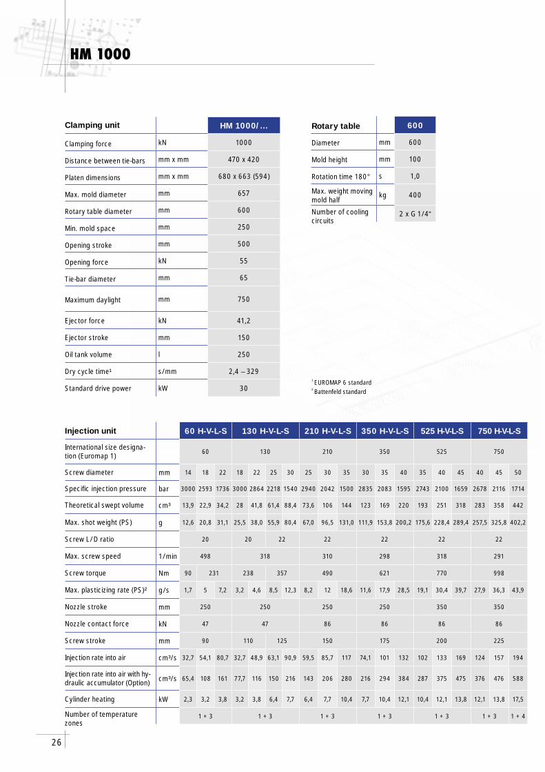
HM 1000
60 H-V-L-S 130 H-V-L-S 210 H-V-L-S 350 H-V-L-S 525 H-V-L-S 750 H-V-L-S
60 130 210 350 525 750
mm 14 18 22 18 22 25 30 25 30 35 30 35 40 35 40 45 40 45 50
bar 3000 2593 1736 3000 2864 2218 1540 2940 2042 1500 2835 2083 1595 2743 2100 1659 2678 2116 1714
cm³ 13,9 22,9 34,2 28 41,8 61,4 88,4 73,6 106 144 123 169 220 193 251 318 283 358 442
g 12,6 20,8 31,1 25,5 38,0 55,9 80,4 67,0 96,5 131,0 111,9 153,8 200,2 175,6 228,4 289,4 257,5 325,8 402,2
20 20 22 22 22 22 22
1/min 498 318 310 298 318 291
Nm 90 231 238 357 490 621 770 998
g/s 1,7 5 7,2 3,2 4,6 8,5 12,3 8,2 12 18,6 11,6 17,9 28,5 19,1 30,4 39,7 27,9 36,3 43,9
mm 250 250 250 250 350 350
kN 47 47 86 86 86 86
mm 90 110 125 150 175 200 225
cm³/s 32,7 54,1 80,7 32,7 48,9 63,1 90,9 59,5 85,7 117 74,1 101 132 102 133 169 124 157 194
cm³/s 65,4 108 161 77,7 116 150 216 143 206 280 216 294 384 287 375 475 376 476 588
kW 2,3 3,2 3,8 3,2 3,8 6,4 7,7 6,4 7,7 10,4 7,7 10,4 12,1 10,4 12,1 13,8 12,1 13,8 17,5
1 + 3 1 + 3 1 + 3 1 + 3 1 + 3 1 + 3 1 + 4
HM 1000/…
kN 1000
mm x mm 470 x 420
mm x mm 680 x 663 (594)
mm 657
mm 600
mm 250
mm 500
kN 55
mm 65
mm 750
kN 41,2
mm 150
l 250
s/mm 2,4 – 329
kW 30
600
mm 600
mm 100
s 1,0
kg 400
2 x G 1/4“
¹ EUROMAP 6 standard² Battenfeld standard
Injection unit
International size designa-tion (Euromap 1)
Screw diameter
Specifi c injection pressure
Theoretical swept volume
Max. shot weight (PS)
Screw L/D ratio
Max. screw speed
Screw torque
Max. plasticizing rate (PS)²
Nozzle stroke
Nozzle contact force
Screw stroke
Injection rate into air
Injection rate into air with hy-draulic accumulator (Option)
Cylinder heating
Number of temperature zones
Clamping unit
Clamping force
Distance between tie-bars
Platen dimensions
Max. mold diameter
Rotary table diameter
Min. mold space
Opening stroke
Opening force
Tie-bar diameter
Maximum daylight
Ejector force
Ejector stroke
Oil tank volume
Dry cycle time¹
Standard drive power
Rotary table
Diameter
Mold height
Rotation time 180°
Max. weight moving mold half
Number of cooling circuits
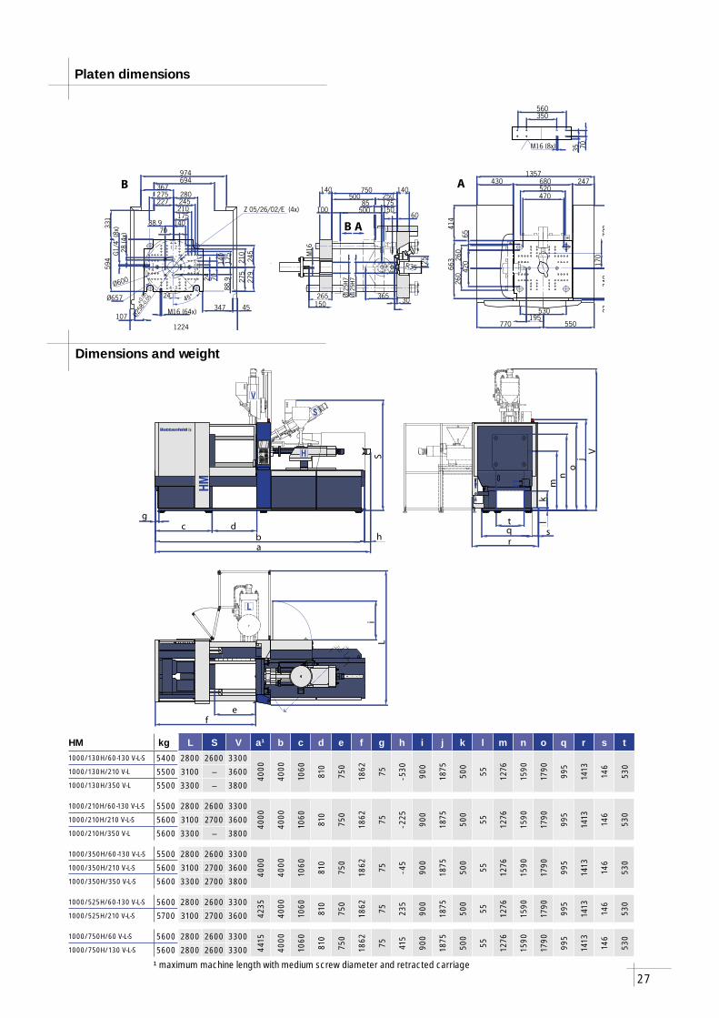
27
l
V
S
H
HM
L
fe
Li
c
a
S
bd
h
g
o
kr
tq
lm
n
jV
s
470
680430 2471357
348
729
6542
0
663
140500
140250
750
Ø125
H7
265 Ø125
H7
30150M
16530
770 550
23
414
M16 (8x) 35 70
350560
60
175
125
195
170
85
520
260
260
R35
365
100 500 150
B A
B A
Ø657
70140175210245280
347
331
594
M16 (64x)107
227
367694974
45
7014
017
5
210
245
1224
279
4
G1/
4"(8
x)
1
4 3
32
21
Ø600
88.9
88.9
28(4
x)
275
275
24
24
Z 05/26/02/E (4x)
Ø258
+0.0
5-0
.05 45°
HM kg L S V a¹ b c d e f g h i j k l m n o q r s t1000/130H/60-130 V-L-S 5400 2800 2600 3300
4000
4000
1060
810
750
1862 75 - 530
900
1875
500
55 1276
1590
1790
995
1413
146
530
1000/130H/210 V-L 5500 3100 – 36001000/130H/350 V-L 5500 3300 – 3800
1000/210H/60-130 V-L-S 5500 2800 2600 3300
4000
4000
1060
810
750
1862 75 - 225
900
1875
500
55 1276
1590
1790
995
1413
146
530
1000/210H/210 V-L-S 5600 3100 2700 36001000/210H/350 V-L 5600 3300 – 3800
1000/350H/60-130 V-L-S 5500 2800 2600 3300
4000
4000
1060
810
750
1862 75 - 45
900
1875
500
55 1276
1590
1790
995
1413
146
530
1000/350H/210 V-L-S 5600 3100 2700 36001000/350H/350 V-L-S 5600 3300 2700 3800
1000/525H/60-130 V-L-S 5600 2800 2600 3300
4235
4000
1060
810
750
1862 75 235
900
1875
500
55 1276
1590
1790
995
1413
146
530
1000/525H/210 V-L-S 5700 3100 2700 3600
1000/750H/60 V-L-S 5600 2800 2600 3300
4415
4000
1060
810
750
1862 75 415
900
1875
500
55 1276
1590
1790
995
1413
146
530
1000/750H/130 V-L-S 5600 2800 2600 3300
Platen dimensions
Dimensions and weight
¹ maximum machine length with medium screw diameter and retracted carriage
28
60 H-V-L-S 130 H-V-L-S 210 H-V-L-S 350 H-V-L-S 525 H-V-L-S 750 H-V-L-S
60 130 210 350 525 750
mm 14 18 22 18 22 25 30 25 30 35 30 35 40 35 40 45 40 45 50
bar 3000 2593 1736 3000 2864 2218 1540 2940 2042 1500 2835 2083 1595 2743 2100 1659 2678 2116 1714
cm³ 13,9 22,9 34,2 28 41,8 61,4 88,4 73,6 106 144 123 169 220 193 251 318 283 358 442
g 12,6 20,8 31,1 25,5 38,0 55,9 80,4 67,0 96,5 131,0 111,9 153,8 200,2 175,6 228,4 289,4 257,5 325,8 402,2
20 20 22 22 22 22 22
1/min 498 318 310 298 318 291
Nm 90 231 238 357 490 621 770 998
g/s 1,7 5 7,2 3,2 4,6 8,5 12,3 8,2 12 18,6 11,6 17,9 28,5 19,1 30,4 39,7 27,9 36,3 43,9
mm 250 250 250 250 350 350
kN 47 47 86 86 86 86
mm 90 110 125 150 175 200 225
cm³/s 32,7 54,1 80,7 32,7 48,9 63,1 90,9 59,5 85,7 117 74,1 101 132 102 133 169 124 157 194
cm³/s 65,4 108 161 77,7 116 150 216 143 206 280 216 294 384 287 375 475 376 476 588
kW 2,3 3,2 3,8 3,2 3,8 6,4 7,7 6,4 7,7 10,4 7,7 10,4 12,1 10,4 12,1 13,8 12,1 13,8 17,5
1 + 3 1 + 3 1 + 3 1 + 3 1 + 3 1 + 3 1 + 4
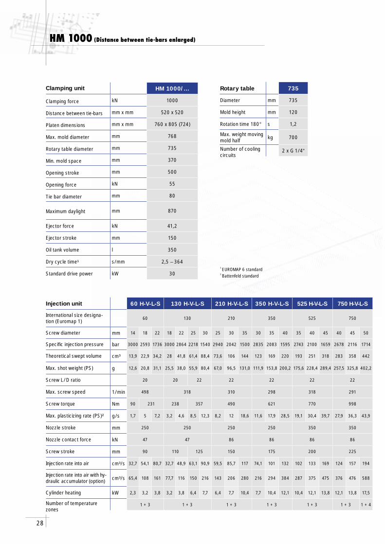
HM 1000/…
kN 1000
mm x mm 520 x 520
mm x mm 760 x 805 (724)
mm 768
mm 735
mm 370
mm 500
kN 55
mm 80
mm 870
kN 41,2
mm 150
l 350
s/mm 2,5 – 364
kW 30
735
mm 735
mm 120
s 1,2
kg 700
2 x G 1/4“
¹ EUROMAP 6 standard² Battenfeld standard
Injection unit
International size designa-tion (Euromap 1)
Screw diameter
Specifi c injection pressure
Theoretical swept volume
Max. shot weight (PS)
Screw L/D ratio
Max. screw speed
Screw torque
Max. plasticizing rate (PS)²
Nozzle stroke
Nozzle contact force
Screw stroke
Injection rate into air
Injection rate into air with hy-draulic accumulator (option)
Cylinder heating
Number of temperature zones
Clamping unit
Clamping force
Distance between tie-bars
Platen dimensions
Max. mold diameter
Rotary table diameter
Min. mold space
Opening stroke
Opening force
Tie bar diameter
Maximum daylight
Ejector force
Ejector stroke
Oil tank volume
Dry cycle time¹
Standard drive power
HM 1000 (Distance between tie-bars enlarged)
Rotary table
Diameter
Mold height
Rotation time 180°
Max. weight moving mold half
Number of cooling circuits
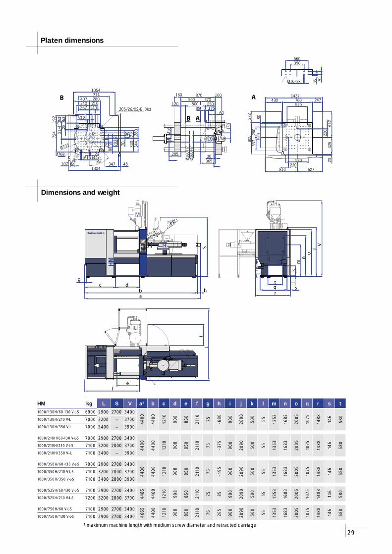
29
l
V
S
H
HM
L
fe
Li
c
a
S
bd
h
g
o
kr
tq
lm
n
jV
s
870 160
Ø16
0H7
30
520
8052
0M16
160500 370 247760430
805
Ø160
H7
580
1437
810 627
272
2342
565
2
285
M16 (8x)
350560
35 7022
0
220
150
250500
365
60175
R35
12085
260
337
B A
B A
Ø768
280
140
280
210
140
70
M16 (44x)
344
107 347 45
210340
192
724
267
407774
1054
1304
Ø735
G1/
4"(8
x)
41
1 2
23
34 88.9 20
3.2
50.8
28(8
x)
24
24
45°
Ø258
+0.0
5-0
.05
Z05/26/02/E (4x)
340
HM kg L S V a¹ b c d e f g h i j k l m n o q r s t1000/130H/60-130 V-L-S 6900 2900 2700 3400
4400
4400
1210
908
850
2110 75 - 680
900
2090
500
55 1353
1683
2005
1075
1488
146
580
1000/130H/210 V-L 7000 3200 – 37001000/130H/350 V-L 7000 3400 – 3900
1000/210H/60-130 V-L-S 7000 2900 2700 3400
4400
4400
1210
908
850
2110 75 - 375
900
2090
500
55 1353
1683
2005
1075
1488
146
580
1000/210H/210 V-L-S 7100 3200 2800 37001000/210H/350 V--L 7100 3400 – 3900
1000/350H/60-130 V-L-S 7000 2900 2700 3400
4400
4400
1210
908
850
2110 75 - 195
900
2090
500
55 1353
1683
2005
1075
1488
146
580
1000/350H/210 V-L-S 7100 3200 2800 37001000/350H/350 V-L-S 7100 3400 2800 3900
1000/525H/60-130 V-L-S 7100 2900 2700 3400
4485
4400
1210
908
850
2110 75 85 900
2090
500
55 1353
1683
2005
1075
1488
146
580
1000/525H/210 V-L-S 7200 3200 2800 3700
1000/750H/60 V-L-S 7100 2900 2700 3400
4665
4400
1210
908
850
2110 75 265
900
2090
500
55 1353
1683
2005
1075
1488
146
580
1000/750H/130 V-L-S 7100 2900 2700 3400
Platen dimensions
Dimensions and weight
¹ maximum machine length with medium screw diameter and retracted carriage
30
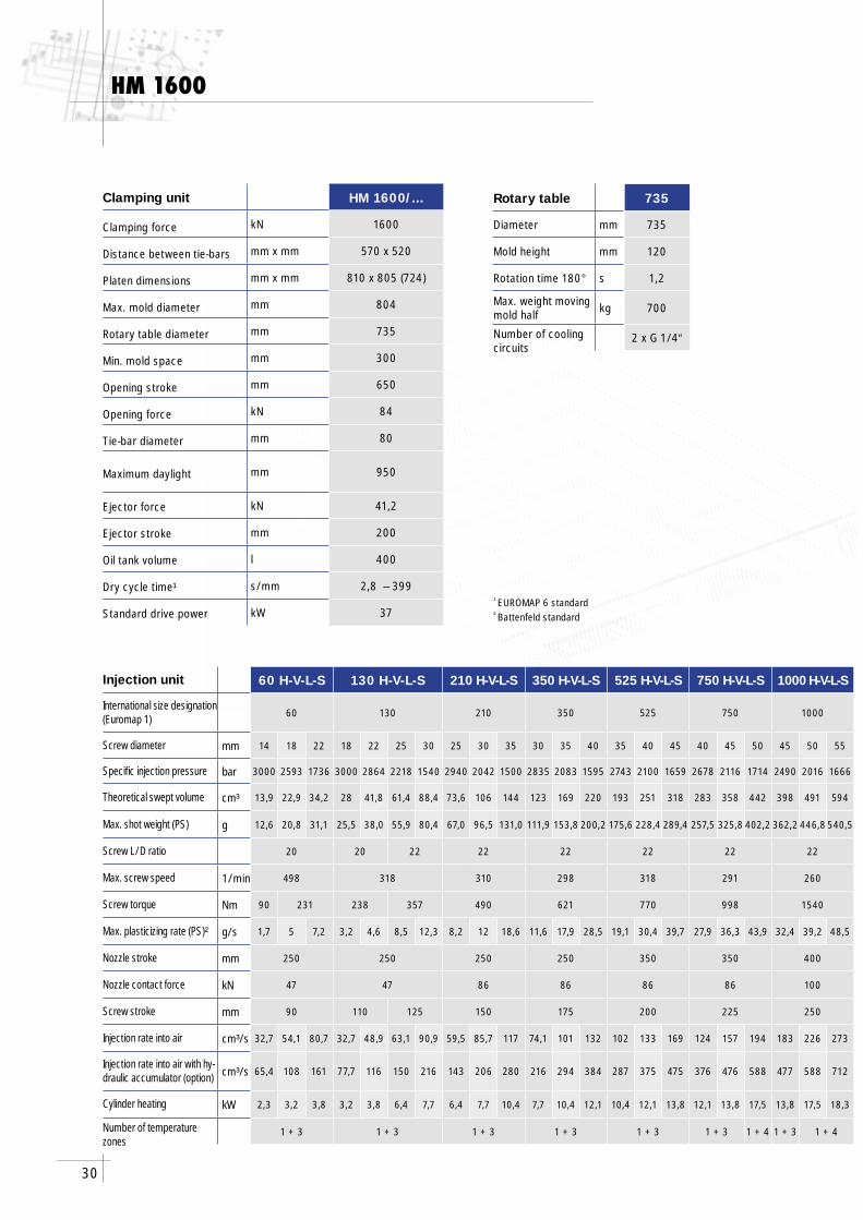
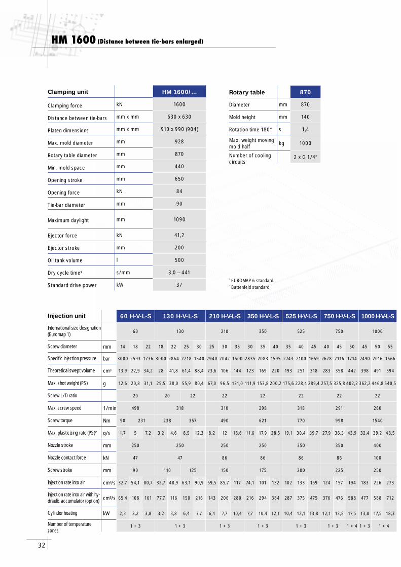
HM 1600
60 H-V-L-S 130 H-V-L-S 210 H-V-L-S 350 H-V-L-S 525 H-V-L-S 750 H-V-L-S 1000 H-V-L-S
60 130 210 350 525 750 1000
mm 14 18 22 18 22 25 30 25 30 35 30 35 40 35 40 45 40 45 50 45 50 55
bar 3000 2593 1736 3000 2864 2218 1540 2940 2042 1500 2835 2083 1595 2743 2100 1659 2678 2116 1714 2490 2016 1666
cm³ 13,9 22,9 34,2 28 41,8 61,4 88,4 73,6 106 144 123 169 220 193 251 318 283 358 442 398 491 594
g 12,6 20,8 31,1 25,5 38,0 55,9 80,4 67,0 96,5 131,0 111,9 153,8 200,2 175,6 228,4 289,4 257,5 325,8 402,2 362,2 446,8 540,5
20 20 22 22 22 22 22 22
1/min 498 318 310 298 318 291 260
Nm 90 231 238 357 490 621 770 998 1540
g/s 1,7 5 7,2 3,2 4,6 8,5 12,3 8,2 12 18,6 11,6 17,9 28,5 19,1 30,4 39,7 27,9 36,3 43,9 32,4 39,2 48,5
mm 250 250 250 250 350 350 400
kN 47 47 86 86 86 86 100
mm 90 110 125 150 175 200 225 250
cm³/s 32,7 54,1 80,7 32,7 48,9 63,1 90,9 59,5 85,7 117 74,1 101 132 102 133 169 124 157 194 183 226 273
cm³/s 65,4 108 161 77,7 116 150 216 143 206 280 216 294 384 287 375 475 376 476 588 477 588 712
kW 2,3 3,2 3,8 3,2 3,8 6,4 7,7 6,4 7,7 10,4 7,7 10,4 12,1 10,4 12,1 13,8 12,1 13,8 17,5 13,8 17,5 18,3
1 + 3 1 + 3 1 + 3 1 + 3 1 + 3 1 + 3 1 + 4 1 + 3 1 + 4
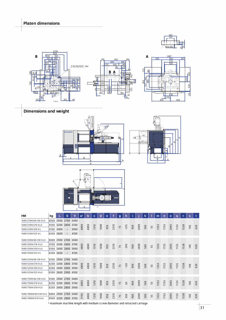
HM 1600/...
kN 1600
mm x mm 570 x 520
mm x mm 810 x 805 (724)
mm 804
mm 735
mm 300
mm 650
kN 84
mm 80
mm 950
kN 41,2
mm 200
l 400
s/mm 2,8 – 399
kW 37
735
mm 735
mm 120
s 1,2
kg 700
2 x G 1/4“
Injection unit
International size designation (Euromap 1)
Screw diameter
Specifi c injection pressure
Theoretical swept volume
Max. shot weight (PS)
Screw L/D ratio
Max. screw speed
Screw torque
Max. plasticizing rate (PS)²
Nozzle stroke
Nozzle contact force
Screw stroke
Injection rate into air
Injection rate into air with hy-draulic accumulator (option)
Cylinder heating
Number of temperature zones
¹ EUROMAP 6 standard² Battenfeld standard
Clamping unit
Clamping force
Distance between tie-bars
Platen dimensions
Max. mold diameter
Rotary table diameter
Min. mold space
Opening stroke
Opening force
Tie-bar diameter
Maximum daylight
Ejector force
Ejector stroke
Oil tank volume
Dry cycle time¹
Standard drive power
Rotary table
Diameter
Mold height
Rotation time 180°
Max. weight moving mold half
Number of cooling circuits
31
l
V
S
H
HM
L
fe
Li
c
a
S
bd
h
g
o
k
r
tq
lm
n
jV
s
950570
520
80
Ø16
0H7
30M
20
180180650 300
805
810 247430
Ø16
0H7
a630
1487
272
2342
565
2
835 652
363
35 70M16 (8x)
350560
150
365
R35
245
220
6017585
520
260
337
120 650 180
B A
B A
Ø804
280
210
140
70
350280210140
70
344
107 347
M16 (56x)
45
189
292
4328241104
724
1354
Ø735
1 2
23
34
G1/
4"(8
x)
1
4
342.5
24 342.
5
2488
.9 203.
2
28(8
x)
50.8
88.9
45°
Ø258
+0.0
5-0
.05
Z 05/26/02/E (4x)
HM kg L S V a¹ b c d e f g h i j k l m n o q r s t1600/210H/60-130 V-L-S 8000 2900 2700 3400
4800
4800
1310
1008
950
2310 75 - 575
900
2090
500
55 1353
1733
2005
1125
1538
146
6301600/210H/210 V-L-S 8100 3200 2800 3700
1600/210H/350 V-L 8100 3400 – 39001600/210H/525 V-L 8200 3600 – 4100
1600/350H/60-130 V-L-S 8000 2900 2700 3400
4800
4800
1310
1008
950
2310 75 - 395
900
2090
500
55 1353
1733
2005
1125
1538
146
6301600/350H/210 V-L-S 8100 3200 2800 3700
1600/350H/350 V-L-S 8100 3400 2800 39001600/350H/525 V-L 8200 3600 – 4100
1600/525H/60-130 V-L-S 8100 2900 2700 3400
4800
4800
1310
1008
950
2310 75 - 120
900
2090
500
55 1353
1733
2005
1125
1538
146
6301600/525H/210 V-L-S 8200 3200 2800 3700
1600/525H/350 V-L-S 8200 3400 2800 39001600/525H/525 V-L-S 8300 3600 2900 4100
1600/750H/60-130 V-L-S 8100 2900 2700 3400
4865
4800
1310
1008
950
2310 75 65 900
2090
500
55 1353
1733
2005
1125
1538
146
630
1600/750H/210 V-L-S 8200 3200 2800 37001600/750H/350 V-L-S 8200 3400 2800 3900
1600/1000H/60-130 V-L-S 8800 2900 2700 3400
5150
4800
1310
1008
950
2310 75 350
900
2090
500
55 1353
1733
2005
1125
1538
146
630
1600/1000H/210 V-L-S 8900 3200 2800 3700
Platen dimensions
Dimensions and weight
¹ maximum machine length with medium screw diameter and retracted carriage
32
60 H-V-L-S 130 H-V-L-S 210 H-V-L-S 350 H-V-L-S 525 H-V-L-S 750 H-V-L-S 1000 H-V-L-S
60 130 210 350 525 750 1000
mm 14 18 22 18 22 25 30 25 30 35 30 35 40 35 40 45 40 45 50 45 50 55
bar 3000 2593 1736 3000 2864 2218 1540 2940 2042 1500 2835 2083 1595 2743 2100 1659 2678 2116 1714 2490 2016 1666
cm³ 13,9 22,9 34,2 28 41,8 61,4 88,4 73,6 106 144 123 169 220 193 251 318 283 358 442 398 491 594
g 12,6 20,8 31,1 25,5 38,0 55,9 80,4 67,0 96,5 131,0 111,9 153,8 200,2 175,6 228,4 289,4 257,5 325,8 402,2 362,2 446,8 540,5
20 20 22 22 22 22 22 22
1/min 498 318 310 298 318 291 260
Nm 90 231 238 357 490 621 770 998 1540
g/s 1,7 5 7,2 3,2 4,6 8,5 12,3 8,2 12 18,6 11,6 17,9 28,5 19,1 30,4 39,7 27,9 36,3 43,9 32,4 39,2 48,5
mm 250 250 250 250 350 350 400
kN 47 47 86 86 86 86 100
mm 90 110 125 150 175 200 225 250
cm³/s 32,7 54,1 80,7 32,7 48,9 63,1 90,9 59,5 85,7 117 74,1 101 132 102 133 169 124 157 194 183 226 273
cm³/s 65,4 108 161 77,7 116 150 216 143 206 280 216 294 384 287 375 475 376 476 588 477 588 712
kW 2,3 3,2 3,8 3,2 3,8 6,4 7,7 6,4 7,7 10,4 7,7 10,4 12,1 10,4 12,1 13,8 12,1 13,8 17,5 13,8 17,5 18,3
1 + 3 1 + 3 1 + 3 1 + 3 1 + 3 1 + 3 1 + 4 1 + 3 1 + 4
HM 1600/...
kN 1600
mm x mm 630 x 630
mm x mm 910 x 990 (904)
mm 928
mm 870
mm 440
mm 650
kN 84
mm 90
mm 1090
kN 41,2
mm 200
l 500
s/mm 3,0 – 441
kW 37
870
mm 870
mm 140
s 1,4
kg 1000
2 x G 1/4“
¹ EUROMAP 6 standard² Battenfeld standard
Clamping unit
Clamping force
Distance between tie-bars
Platen dimensions
Max. mold diameter
Rotary table diameter
Min. mold space
Opening stroke
Opening force
Tie-bar diameter
Maximum daylight
Ejector force
Ejector stroke
Oil tank volume
Dry cycle time¹
Standard drive power
Injection unit
International size designation (Euromap 1)
Screw diameter
Specifi c injection pressure
Theoretical swept volume
Max. shot weight (PS)
Screw L/D ratio
Max. screw speed
Screw torque
Max. plasticizing rate (PS)²
Nozzle stroke
Nozzle contact force
Screw stroke
Injection rate into air
Injection rate into air with hy-draulic accumulator (option)
Cylinder heating
Number of temperature zones
HM 1600 (Distance between tie-bars enlarged)
Rotary table
Diameter
Mold height
Rotation time 180°
Max. weight moving mold half
Number of cooling circuits

33
l
V
S
H
HM
L
fe
Li
c
a
S
bd
h
g
o
kr
tq
lm
n
jV
s
150
M20 (8x)
560840
35 140
440
Ø16
0H7
30
200
a
200
200383
M20
1090650
Ø16
0H7
300650
60175
365
45140 520
435
260
245
712
1607257
990 63
0
895650
910630
237
440
90
M20
(80x
)
245
B A
B A
Ø928
R35
415
34
4
1
1 2
2
3
Ø870
420
420
M20 (80x)
1474
1224944
140210280350
894
117
492
154 352
439
45357
350
210
280
140
50.888.9
88.9 20
3.2
7024
G1/
4"(8
x)28
(8x)
45°
Ø258
+0.0
5-0
.05
Z 05/26/02/E (4x)
415
HM kg L S V a¹ b c d e f g h i j k l m n o q r s t1600/210H/60-130 V-L-S 10200 3000 2700 3500
5050
5050
1460
1108
1050
2560 75 - 575
900
2240
500
55 1463
1858
2155
1245
1621
146
6701600/210H/210 V-L-S 10300 3300 2800 3800
1600/210H/350 V-L 10300 3500 – 40001600/210H/525 V-L 10300 3700 – 4200
1600/350H/60-130 V-L-S 10200 3000 2700 3500
5050
5050
1460
1108
1050
2560 75 - 395
900
2240
500
55 1463
1858
2155
1245
1621
146
6701600/350H/210 V-L-S 10300 3300 2800 3800
1600/350H/350 V-L-S 10300 3500 2800 40001600/350H/525 V-L 10300 3700 – 4200
1600/525H/60-130 V-L-S 10300 3000 2700 3500
5050
5050
1460
1108
1050
2560 75 - 120
900
2240
500
55 1463
1858
2155
1245
1621
146
6701600/525H/210 V-L-S 10400 3300 2800 3800
1600/525H/350 V-L-S 10400 3500 2800 40001600/525H/525 V-L-S 10500 3700 2900 4200
1600/750H/60-130 V-L-S 10300 3000 2700 3500
5115
5050
1460
1108
1050
2560 75 65 900
2240
500
55 1463
1858
2155
1245
1621
146
670
1600/750H/210 V-L-S 10400 3300 2800 38001600/750H/350 V-L-S 10400 3500 2800 4000
1600/1000H/60-130 V-L-S 11000 3000 2700 3500
5400
5050
1460
1108
1050
2560 75 350
900
2240
500
55 1463
1858
2155
1245
1621
146
670
1600/1000H/210 V-L-S 11100 3300 2800 3800
Platen dimensions
Dimensions and weight
¹ maximum machine length with medium screw diameter and retracted carriage
34
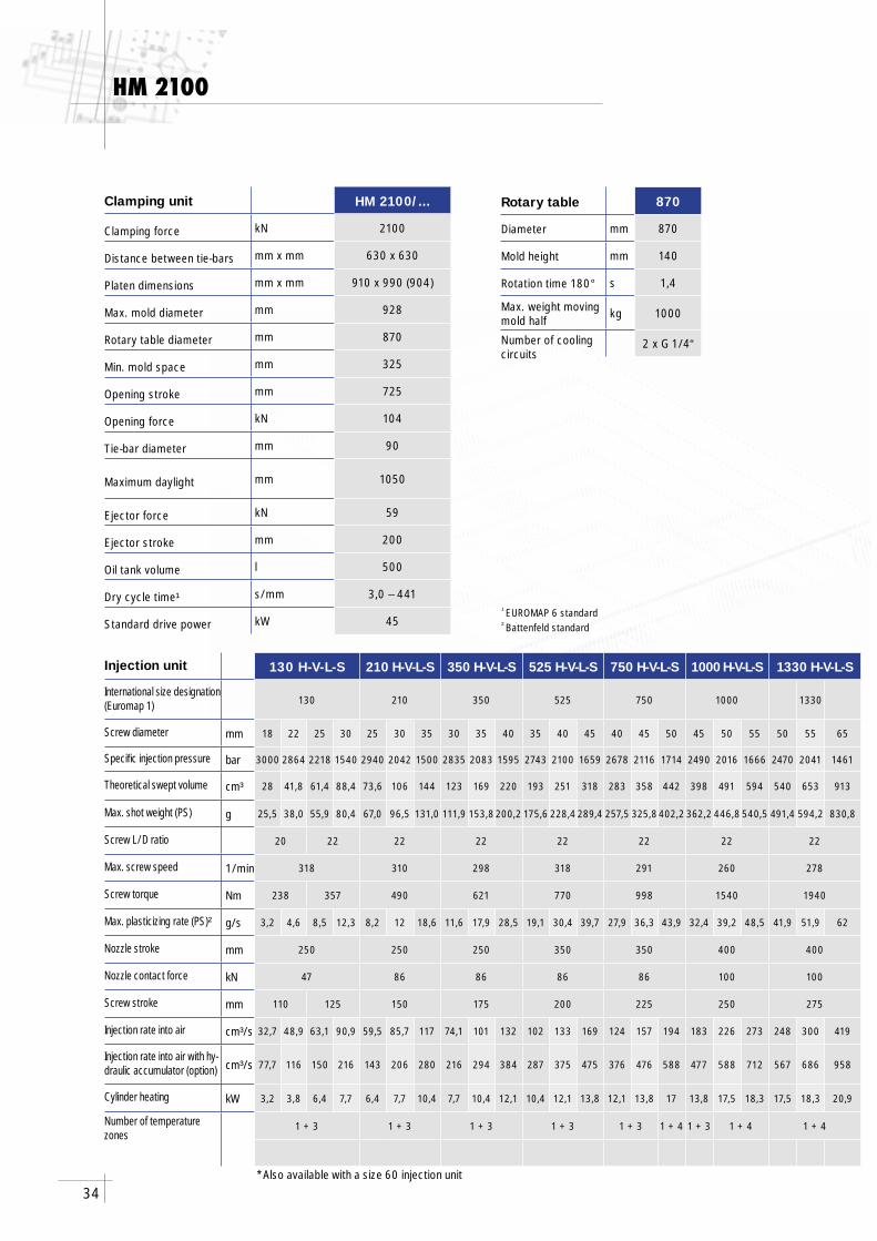
HM 2100
130 H-V-L-S 210 H-V-L-S 350 H-V-L-S 525 H-V-L-S 750 H-V-L-S 1000 H-V-L-S 1330 H-V-L-S
130 210 350 525 750 1000 1330
mm 18 22 25 30 25 30 35 30 35 40 35 40 45 40 45 50 45 50 55 50 55 65
bar 3000 2864 2218 1540 2940 2042 1500 2835 2083 1595 2743 2100 1659 2678 2116 1714 2490 2016 1666 2470 2041 1461
cm³ 28 41,8 61,4 88,4 73,6 106 144 123 169 220 193 251 318 283 358 442 398 491 594 540 653 913
g 25,5 38,0 55,9 80,4 67,0 96,5 131,0 111,9 153,8200,2 175,6 228,4289,4 257,5 325,8402,2 362,2 446,8 540,5 491,4 594,2 830,8
20 22 22 22 22 22 22 22
1/min 318 310 298 318 291 260 278
Nm 238 357 490 621 770 998 1540 1940
g/s 3,2 4,6 8,5 12,3 8,2 12 18,6 11,6 17,9 28,5 19,1 30,4 39,7 27,9 36,3 43,9 32,4 39,2 48,5 41,9 51,9 62
mm 250 250 250 350 350 400 400
kN 47 86 86 86 86 100 100
mm 110 125 150 175 200 225 250 275
cm³/s 32,7 48,9 63,1 90,9 59,5 85,7 117 74,1 101 132 102 133 169 124 157 194 183 226 273 248 300 419
cm³/s 77,7 116 150 216 143 206 280 216 294 384 287 375 475 376 476 588 477 588 712 567 686 958
kW 3,2 3,8 6,4 7,7 6,4 7,7 10,4 7,7 10,4 12,1 10,4 12,1 13,8 12,1 13,8 17 13,8 17,5 18,3 17,5 18,3 20,9
1 + 3 1 + 3 1 + 3 1 + 3 1 + 3 1 + 4 1 + 3 1 + 4 1 + 4
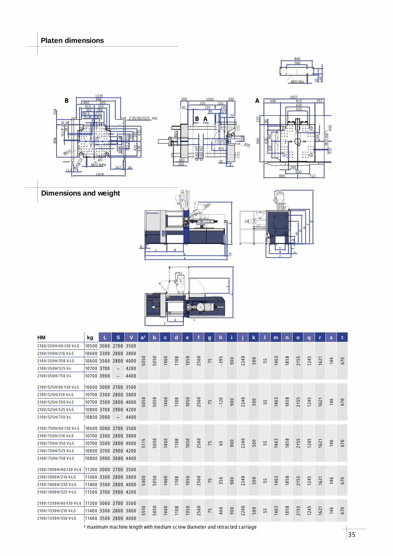
HM 2100/...
kN 2100
mm x mm 630 x 630
mm x mm 910 x 990 (904)
mm 928
mm 870
mm 325
mm 725
kN 104
mm 90
mm 1050
kN 59
mm 200
l 500
s/mm 3,0 – 441
kW 45
870
mm 870
mm 140
s 1,4
kg 1000
2 x G 1/4“
Injection unit
International size designation (Euromap 1)
Screw diameter
Specifi c injection pressure
Theoretical swept volume
Max. shot weight (PS)
Screw L/D ratio
Max. screw speed
Screw torque
Max. plasticizing rate (PS)²
Nozzle stroke
Nozzle contact force
Screw stroke
Injection rate into air
Injection rate into air with hy-draulic accumulator (option)
Cylinder heating
Number of temperature zones
¹ EUROMAP 6 standard² Battenfeld standard
Clamping unit
Clamping force
Distance between tie-bars
Platen dimensions
Max. mold diameter
Rotary table diameter
Min. mold space
Opening stroke
Opening force
Tie-bar diameter
Maximum daylight
Ejector force
Ejector stroke
Oil tank volume
Dry cycle time¹
Standard drive power
Rotary table
Diameter
Mold height
Rotation time 180°
Max. weight moving mold half
Number of cooling circuits
*Also available with a size 60 injection unit
35
l
V
S
H
HM
L
fe
Li
c
a
S
bd
h
g
o
k
r
tq
lm
n
jV
s
150
M20 (8x)
560840
35 140
325
Ø160
H7
30
200
a
200
200383
M20
1050725
Ø160
H7
185725
75225
415
85140 520
435
260
245
712
692
535
23
1607257
990
630
895650
910630
237
440
90
M20
(68*
)
245
B A
B A
R35
410
34
4
1
1 2
2
3
Ø870
420
420
M20 (68x)
1474
1224944
140210280350
894
117
492
154 352
439
45357
350
210
280
140
50.888.9
88.9 20
3.2
G1/
4"(8
x)28
(8x)
45°
Ø258
+0.0
5-0
.05
Z 05/26/02/E (4x)
410
HM kg L S V a¹ b c d e f g h i j k l m n o q r s t2100/350H/60-130 V-L-S 10500 3000 2700 3500
5050
5050
1460
1108
1050
2560 75 - 395
900
2240
500
55 1463
1858
2155
1245
1621
146
670
2100/350H/210 V-L-S 10600 3300 2800 38002100/350H/350 V-L-S 10600 3500 2800 40002100/350H/525 V-L 10700 3700 – 42002100/350H/750 V-L 10700 3900 – 4400
2100/525H/60-130 V-L-S 10600 3000 2700 3500
5050
5050
1460
1108
1050
2560 75 - 120
900
2240
500
55 1463
1858
2155
1245
1621
146
670
2100/525H/210 V-L-S 10700 3300 2800 38002100/525H/350 V-L-S 10700 3500 2800 40002100/525H/525 V-L-S 10800 3700 2900 42002100/525H/750 V-L 10800 3900 – 4400
2100/750H/60-130 V-L-S 10600 3000 2700 3500
5115
5050
1460
1108
1050
2560 75 65 900
2240
500
55 1463
1858
2155
1245
1621
146
670
2100/750H/210 V-L-S 10700 3300 2800 38002100/750H/350 V-L-S 10700 3500 2800 40002100/750H/525 V-L-S 10800 3700 2900 42002100/750H/750 V-L-S 10800 3900 3000 4400
2100/1000H/60-130 V-L-S 11300 3000 2700 3500
5400
5050
1460
1108
1050
2560 75 350
900
2240
500
55 1463
1858
2155
1245
1621
146
6702100/1000H/210 V-L-S 11400 3300 2800 3800
2100/1000H/350 V-L-S 11400 3500 2800 40002100/1000H/525 V-L-S 11500 3700 2900 4200
2100/1330H/60-130 V-L-S 11300 3000 2700 3500
5510
5050
1460
1108
1050
2560 75 460
900
2240
500
55 1463
1858
2155
1245
1621
146
670
2100/1330H/210 V-L-S 11400 3300 2800 38002100/1330H/350 V-L-S 11400 3500 2800 4000
Platen dimensions
Dimensions and weight
¹ maximum machine length with medium screw diameter and retracted carriage

36
HM 2700
210 H-V-L-S 350 H-V-L-S 525 H-V-L-S 750 H-V-L-S 1000 H-V-L-S 1330 H-V-L-S 2200 H-V-L-S
210 350 525 750 1000 1330 2200
mm 25 30 35 30 35 40 35 40 45 40 45 50 45 50 55 50 55 65 55 65 75
bar 2940 2042 1500 2835 2083 1595 2743 2100 1659 2678 2116 1714 2490 2016 1666 2470 2041 1461 2500 2070 1555
cm³ 73,6 106 144 123 169 220 193 251 318 283 358 442 398 491 594 540 653 913 772 1078 1436
g 67,0 96,5 131,0 111,9 153,8 200,2 175,6 228,4 289,4 257,5 325,8 402,2 362,2 446,8 540,5 491,4 594,2 830,8 702,5 981,0 1306,8
22 22 22 22 22 22 22
1/min 310 298 318 291 260 278 283
Nm 490 621 770 998 1540 1940 2373
g/s 8,2 12 18,6 11,6 17,9 28,5 19,1 30,4 39,7 27,9 36,3 43,9 32,4 39,2 48,5 41,9 51,9 62 52,8 63,1 78
mm 250 250 350 350 400 400 500
kN 86 86 86 86 100 100 129
mm 150 175 200 225 250 275 325
cm³/s 59,5 85,7 117 74,1 101 132 102 133 169 124 157 194 183 226 273 248 300 419 242 338 450
cm³/s 143 206 280 216 294 384 287 375 475 376 476 588 477 588 712 567 686 958 484 676 900
kW 6,4 7,7 10,4 7,7 10,4 12,1 10,4 12,1 13,8 12,1 13,8 17,5 13,8 17,5 18,3 17,5 18,3 20,9 22,7 26,6 31,3
1 + 3 1 + 3 1 + 3 1 + 3 1 + 4 1 + 3 1 + 4 1 + 4 1 + 4
HM 2700/...
kN 2700
mm x mm 710 x 710
mm x mm 1030 x 1100 (1000)
mm 1047
mm 1000
mm 350
mm 800
kN 141
mm 105
mm 1150
kN 59
mm 200
l 550
s/mm 3,4 – 497
kW 55
1000
mm 1000
mm 160
s 1,6
kg 1500
2 x G 3/8“
Injection unit
International size designation (Euromap 1)
Screw diameter
Specifi c injection pressure
Theoretical swept volume
Max. shot weight (PS)
Screw L/D ratio
Max. screw speed
Screw torque
Max. plasticizing rate (PS)²
Nozzle stroke
Nozzle contact force
Screw stroke
Injection rate into air
Injection rate into air with hy-draulic accumulator (Option)
Cylinder heating
Number of temperature zones
¹ EUROMAP 6 standard² Battenfeld standard
Clamping unit
Clamping force
Distance between tie-bars
Platen dimensions
Max. mold diameter
Rotary table diameter
Min. mold space
Opening stroke
Opening force
Tie-bar diameter
Maximum daylight
Ejector force
Ejector stroke
Oil tank volume
Dry cycle time¹
Standard drive power
Rotary table
Diameter
Mold height
Rotation time 180°
Max. weight moving mold half
Number of cooling circuits
*Also available with a size 60 and 130 injection unit
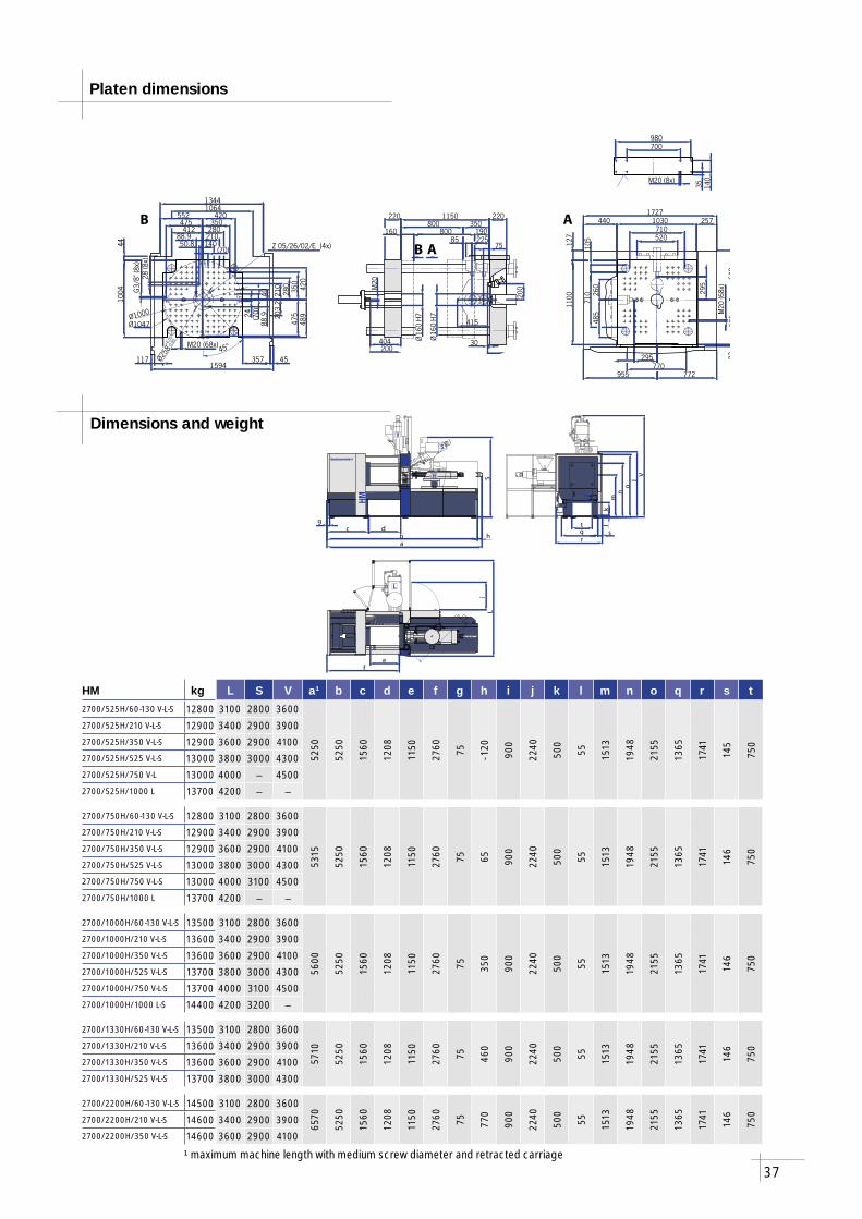
37
l
V
S
H
HM
L
fe
Li
c
a
S
bd
h
g
o
k
r
tq
lm
n
jV
s
200
350
Ø16
0H7
30
220220
200404
M20
1150800
Ø16
0H7
190800
75225
415
85160
520
485
260
295
772
642
585
23
1727257
1100 710
955770
1030710
127
440
105
M20
(68x
)
295
140
35
980700
M20 (8x)
B A
B A475
34
41
1 2
23
420
350
M20 (68x)
1594
13441064
140210280350
1004
117
552
44
412
489
45357
280
140 21
0
(70)
50.888.9
88.9Ø1000
Ø1047
420
(70)24 20
3.2
G3/
8"(8
x)28
(8x)
45°
Ø258
-0.05
Z 05/26/02/E (4x)
475
+0.0
5
HM kg L S V a¹ b c d e f g h i j k l m n o q r s t2700/525H/60-130 V-L-S 12800 3100 2800 3600
5250
5250
1560
1208
1150
2760 75 - 120
900
2240
500
55 1513
1948
2155
1365
1741
145
750
2700/525H/210 V-L-S 12900 3400 2900 39002700/525H/350 V-L-S 12900 3600 2900 41002700/525H/525 V-L-S 13000 3800 3000 43002700/525H/750 V-L 13000 4000 – 45002700/525H/1000 L 13700 4200 – –
2700/750H/60-130 V-L-S 12800 3100 2800 3600
5315
5250
1560
1208
1150
2760 75 65 900
2240
500
55 1513
1948
2155
1365
1741
146
750
2700/750H/210 V-L-S 12900 3400 2900 39002700/750H/350 V-L-S 12900 3600 2900 41002700/750H/525 V-L-S 13000 3800 3000 43002700/750H/750 V-L-S 13000 4000 3100 45002700/750H/1000 L 13700 4200 – –
2700/1000H/60-130 V-L-S 13500 3100 2800 3600
5600
5250
1560
1208
1150
2760 75 350
900
2240
500
55 1513
1948
2155
1365
1741
146
750
2700/1000H/210 V-L-S 13600 3400 2900 39002700/1000H/350 V-L-S 13600 3600 2900 41002700/1000H/525 V-L-S 13700 3800 3000 43002700/1000H/750 V-L-S 13700 4000 3100 45002700/1000H/1000 L-S 14400 4200 3200 –
2700/1330H/60-130 V-L-S 13500 3100 2800 3600
5710
5250
1560
1208
1150
2760 75 460
900
2240
500
55 1513
1948
2155
1365
1741
146
7502700/1330H/210 V-L-S 13600 3400 2900 3900
2700/1330H/350 V-L-S 13600 3600 2900 41002700/1330H/525 V-L-S 13700 3800 3000 4300
2700/2200H/60-130 V-L-S 14500 3100 2800 3600
6570
5250
1560
1208
1150
2760 75 770
900
2240
500
55 1513
1948
2155
1365
1741
146
750
2700/2200H/210 V-L-S 14600 3400 2900 39002700/2200H/350 V-L-S 14600 3600 2900 4100
Platen dimensions
Dimensions and weight
¹ maximum machine length with medium screw diameter and retracted carriage
38
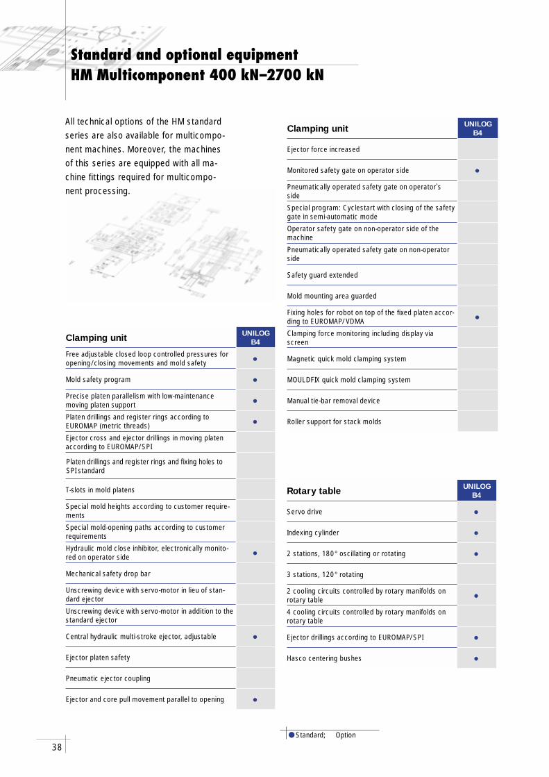
Standard and optional equipmentHM Multicomponent 400 kN–2700 kN
● Standard; Option
Clamping unit UNILOGB4
Free adjustable closed loop controlled pressures for opening/closing movements and mold safety •Mold safety program •Precise platen parallelism with low-maintenancemoving platen support •Platen drillings and register rings according to EUROMAP (metric threads) •Ejector cross and ejector drillings in moving platen according to EUROMAP/SPI
Platen drillings and register rings and fixing holes to SPI standard
T-slots in mold platens
Special mold heights according to customer require-ments
Special mold-opening paths according to customer requirements
Hydraulic mold close inhibitor, electronically monito-red on operator side •Mechanical safety drop bar
Unscrewing device with servo-motor in lieu of stan-dard ejector
Unscrewing device with servo-motor in addition to the standard ejector
Central hydraulic multi-stroke ejector, adjustable •Ejector platen safety
Pneumatic ejector coupling
Ejector and core pull movement parallel to opening •
Clamping unit UNILOGB4
Ejector force increased
Monitored safety gate on operator side •Pneumatically operated safety gate on operator`s side
Special program: Cyclestart with closing of the safety gate in semi-automatic mode
Operator safety gate on non-operator side of the machine
Pneumatically operated safety gate on non-operator side
Safety guard extended
Mold mounting area guarded
Fixing holes for robot on top of the fi xed platen accor-ding to EUROMAP/VDMA •Clamping force monitoring including display via screen
Magnetic quick mold clamping system
MOULDFIX quick mold clamping system
Manual tie-bar removal device
Roller support for stack molds
Rotary table UNILOGB4
Servo drive •Indexing cylinder •2 stations, 180° oscillating or rotating •3 stations, 120° rotating
2 cooling circuits controlled by rotary manifolds on rotary table •4 cooling circuits controlled by rotary manifolds on rotary table
Ejector drillings according to EUROMAP/SPI •Hasco centering bushes •
All technical options of the HM standard series are also available for multicompo-nent machines. Moreover, the machines of this series are equipped with all ma-chine fi ttings required for multicompo-nent processing.
39
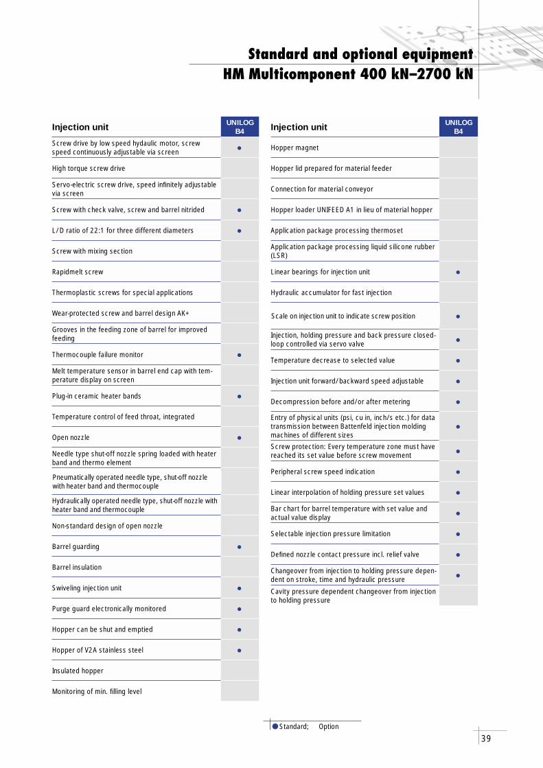
Injection unit UNILOGB4
Screw drive by low speed hydaulic motor, screw speed continuously adjustable via screen •High torque screw drive
Servo-electric screw drive, speed infi nitely adjustable via screen
Screw with check valve, screw and barrel nitrided •L/D ratio of 22:1 for three different diameters •Screw with mixing section
Rapidmelt screw
Thermoplastic screws for special applications
Wear-protected screw and barrel design AK+
Grooves in the feeding zone of barrel for improved feeding
Thermocouple failure monitor •Melt temperature sensor in barrel end cap with tem-perature display on screen
Plug-in ceramic heater bands •Temperature control of feed throat, integrated
Open nozzle •Needle type shut-off nozzle spring loaded with heater band and thermo element
Pneumatically operated needle type, shut-off nozzle with heater band and thermocouple
Hydraulically operated needle type, shut-off nozzle with heater band and thermocouple
Non-standard design of open nozzle
Barrel guarding •Barrel insulation
Swiveling injection unit •Purge guard electronically monitored •Hopper can be shut and emptied •Hopper of V2A stainless steel •Insulated hopper
Monitoring of min. fi lling level
Injection unit UNILOGB4
Hopper magnet
Hopper lid prepared for material feeder
Connection for material conveyor
Hopper loader UNIFEED A1 in lieu of material hopper
Application package processing thermoset
Application package processing liquid silicone rubber (LSR)
Linear bearings for injection unit •Hydraulic accumulator for fast injection
Scale on injection unit to indicate screw position •Injection, holding pressure and back pressure closed-loop controlled via servo valve •Temperature decrease to selected value •Injection unit forward/backward speed adjustable •Decompression before and/or after metering •Entry of physical units (psi, cu in, inch/s etc.) for data transmission between Battenfeld injection molding machines of different sizes
•Screw protection: Every temperature zone must have reached its set value before screw movement •Peripheral screw speed indication •Linear interpolation of holding pressure set values •Bar chart for barrel temperature with set value and actual value display •Selectable injection pressure limitation •Defi ned nozzle contact pressure incl. relief valve •Changeover from injection to holding pressure depen-dent on stroke, time and hydraulic pressure •Cavity pressure dependent changeover from injection to holding pressure
Standard and optional equipmentHM Multicomponent 400 kN–2700 kN
● Standard; Option
40
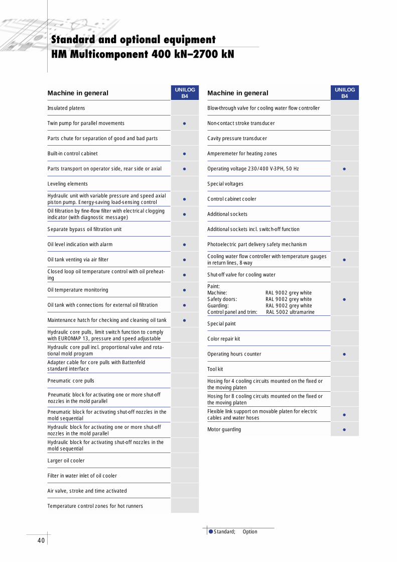
Standard and optional equipmentHM Multicomponent 400 kN–2700 kN
● Standard; Option
Machine in general UNILOGB4
Insulated platens
Twin pump for parallel movements •Parts chute for separation of good and bad parts
Built-in control cabinet •Parts transport on operator side, rear side or axial •Leveling elements
Hydraulic unit with variable pressure and speed axial piston pump. Energy-saving load-sensing control •Oil fi ltration by fi ne-fl ow fi lter with electrical clogging indicator (with diagnostic message) •Separate bypass oil fi ltration unit
Oil level indication with alarm •Oil tank venting via air fi lter •Closed loop oil temperature control with oil preheat-ing •Oil temperature monitoring •Oil tank with connections for external oil fi ltration •Maintenance hatch for checking and cleaning oil tank •Hydraulic core pulls, limit switch function to comply with EUROMAP 13, pressure and speed adjustable
Hydraulic core pull incl. proportional valve and rota-tional mold program
Adapter cable for core pulls with Battenfeld standard interface
Pneumatic core pulls
Pneumatic block for activating one or more shut-off nozzles in the mold parallel
Pneumatic block for activating shut-off nozzles in the mold sequential
Hydraulic block for activating one or more shut-off nozzles in the mold parallel
Hydraulic block for activating shut-off nozzles in the mold sequential
Larger oil cooler
Filter in water inlet of oil cooler
Air valve, stroke and time activated
Temperature control zones for hot runners
Machine in general UNILOGB4
Blow-through valve for cooling water flow controller
Non-contact stroke transducer
Cavity pressure transducer
Amperemeter for heating zones
Operating voltage 230/400 V-3PH, 50 Hz •Special voltages
Control cabinet cooler
Additional sockets
Additional sockets incl. switch-off function
Photoelectric part delivery safety mechanism
Cooling water flow controller with temperature gauges in return lines, 8-way •Shut-off valve for cooling water
Paint:Machine: RAL 9002 grey whiteSafety doors: RAL 9002 grey whiteGuarding: RAL 9002 grey whiteControl panel and trim: RAL 5002 ultramarine
•
Special paint
Color repair kit
Operating hours counter •Tool kit
Hosing for 4 cooling circuits mounted on the fixed or the moving platen
Hosing for 8 cooling circuits mounted on the fixed or the moving platen
Flexible link support on movable platen for electric cables and water hoses •Motor guarding •
41
Standard and optional equipmentHM Multicomponent 400 kN–2700 kN
● Standard; Option
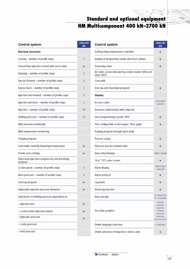
Control system UNILOGB4
Machine functions
Closing – number of profi le steps 5
Closed loop injection control with servo valve •Opening – number of profi le steps 5
Ejector forward – number of profi le steps 3
Ejector back – number of profi le steps 3
Injection unit forward – number of profi le steps 3
Injection unit back – number of profi le steps 3
Injection – number of profi le steps 10
Holding pressure – number of profi le steps 10
Melt pressure monitoring
Melt temperature monitoring
Purging program
Selectable stand-by (lowering) temperature •Stroke zero settings •Open loop injection-compression and breathing program
Screw speed – number of profi le steps 6
Back pressure – number of profi le steps 6
Start-up program •Adjustable injection pressure limitation •Switchover to holding pressure dependent on
– injection time •– screw stroke/injection volume •– hydraulic pressure •– cavity pressure
– melt pressure
Control system UNILOGB4
Self-teaching temperature controller •Display of temperature inside electrical cabinet •Seven-day timer •Air valve, action indicated by stroke marker (ON) and timer (OFF)
Core pulls
Start-up and shut-down program •Display
Access codes password system
Entrance authorization with chipcard
User programming system “APS“ •Free confi gurable screen pages “User page“ •Purging program through open mold
Process setup •Physical, process-related units •Data entry/display table / graph
10.4 “ TFT color screen •Alarm display fault codes
and text
Alarm protocol •Log book •Hardcopy function •Data storage
3.5 fl oppy disk, PC compatible
Set value graphics
closing,opening,injection,holding
pressure,metering,
back pressure
Online language selection 4 languages
Online selection of imperial or metric units •
42
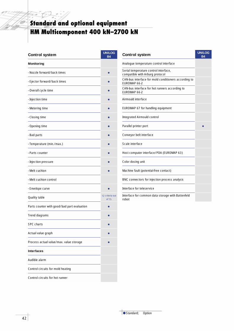
Standard and optional equipmentHM Multicomponent 400 kN–2700 kN
● Standard; Option
Control system UNILOGB4
Monitoring
- Nozzle forward/back times •- Ejector forward/back times •- Overall cycle time •- Injection time •- Metering time •- Closing time •- Opening time •- Bad parts •- Temperature (min./max.) •- Parts counter •- Injection pressure •- Melt cushion •- Melt cushion control
- Envelope curve •Quality table 12 criteria out
of 75
Parts counter with good/bad part evaluation •Trend diagrams •SPC charts •Actual value graph •Process actual value/max. value storage •Interfaces
Audible alarm
Control circuits for mold heating
Control circuits for hot runner
Control system UNILOGB4
Analogue temperature control interface
Serial temperature control interface, compatible with Arburg protocol
CAN-bus interface for mold conditioners according to EUROMAP 66-2
CAN-bus interface for hot runners according to EUROMAP 66-2
Airmould interface
EUROMAP 67 for handling equipment
Integrated Airmould control
Parallel printer port •Conveyor belt interface
Scale interface
Host computer interface/PDA (EUROMAP 63)
Color dosing unit
Machine fault (potential-free contact)
BNC connectors for injection process analysis
Interface for teleservice
Interface for common data storage with Battenfeld robot

We have taken great care to collect the data and technical information in this publication. However, this publication could contain technical inaccura-cies or typographical errors. We reserve the right to make improvements or changes to this publication and to the products at any time.

THE POWER to SUCCEED
Battenfeld GmbHScherl 10 · 58540 Meinerzhagen · GermanyTel. +49 2354 72-0 · Fax +49 2354 [email protected]
Battenfeld Kunststoffmaschinen Ges. m. b. H.Wiener Neustädter Straße 81 · 2542 Kottingbrunn · AustriaTel. +43 2252 404-0 · Fax +43 2252 [email protected]
www.battenfeld.com IMT
09/0
4 (T
S09
/04)
AR
, 400
0, E
S
ubje
ct to
cha
nge