Embed Size (px)
DESCRIPTION
Civil Engineering
Citation preview
Dr. Nauman KHURRAM
Assistant Professor
Department of Civil Engineering
Structural Mechanics (CE- 312)
Cylinders and Pressure Vassals
UNIVERSITY OF ENGINEERING
& TECHNOLOGY LAHORE
By Dr. Nauman KHURRAM Department of Civil Engineering, UET Lahore 2
Cylinders are generally meant to contain fluids (liquid &
gas).
Cylinders must be strong enough to bear all the
stress/pressure subjected by the containing fluid otherwise
they will burst.
In order to make them safe and durable, we should either
choose a stronger material on increase the thickness.
CYLINDERS
Examples of cylinders are
Cylindrical vassal: tankers petroleum and water etc.
Pipes, conduits or ducts in which fluid is flowing under
pressure, a shallow length of these ducts and pips act as a
cylinder
3 By Dr. Nauman KHURRAM Department of Civil Engineering, UET Lahore
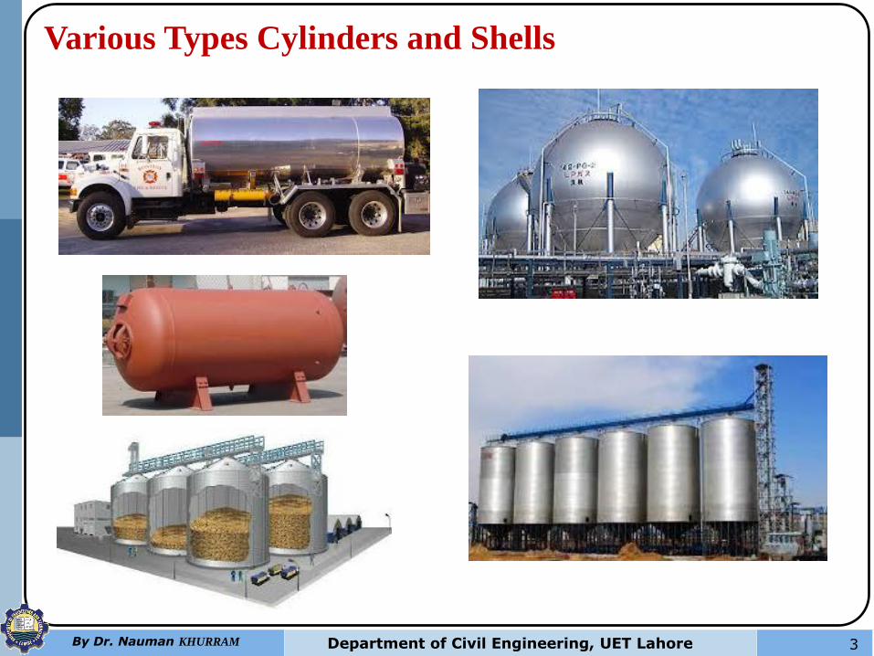
Various Types Cylinders and Shells
4 By Dr. Nauman KHURRAM Department of Civil Engineering, UET Lahore
Types of Cylinders
1. Thin cylinders
2. Thick cylinders
1. THIN CYLINDERS
These are the cylinders which has diameter more than 20 times
of the thickness of the wall (or shell).
when a thin cylinder is subjected to internal pressure, three
mutually perpendicular stresses are set up in the cylinder
material, namely the Circumferential or Hoop Stress,
Longitudinal Stress and Radial Stress.
Characteristics/Assumption of Thin Cylinders
The following assumptions are made in order to derive the
expression for stress and strains in thin cylinders.
1. The ratio between inside diameter (d) and thickness (t)
is more than 20.
5 By Dr. Nauman KHURRAM Department of Civil Engineering, UET Lahore
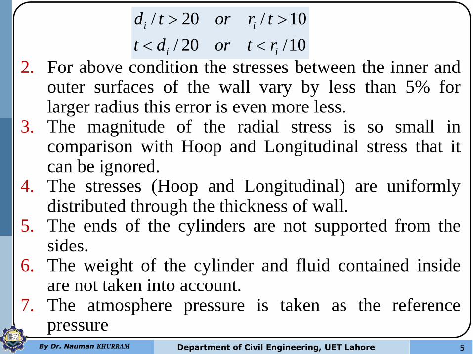
2. For above condition the stresses between the inner and outer surfaces of the wall vary by less than 5% for larger radius this error is even more less.
3. The magnitude of the radial stress is so small in comparison with Hoop and Longitudinal stress that it can be ignored.
4. The stresses (Hoop and Longitudinal) are uniformly distributed through the thickness of wall.
5. The ends of the cylinders are not supported from the sides.
6. The weight of the cylinder and fluid contained inside are not taken into account.
7. The atmosphere pressure is taken as the reference pressure
10/20/
10/20/
ii
ii
rtordt
trortd
6 By Dr. Nauman KHURRAM Department of Civil Engineering, UET Lahore
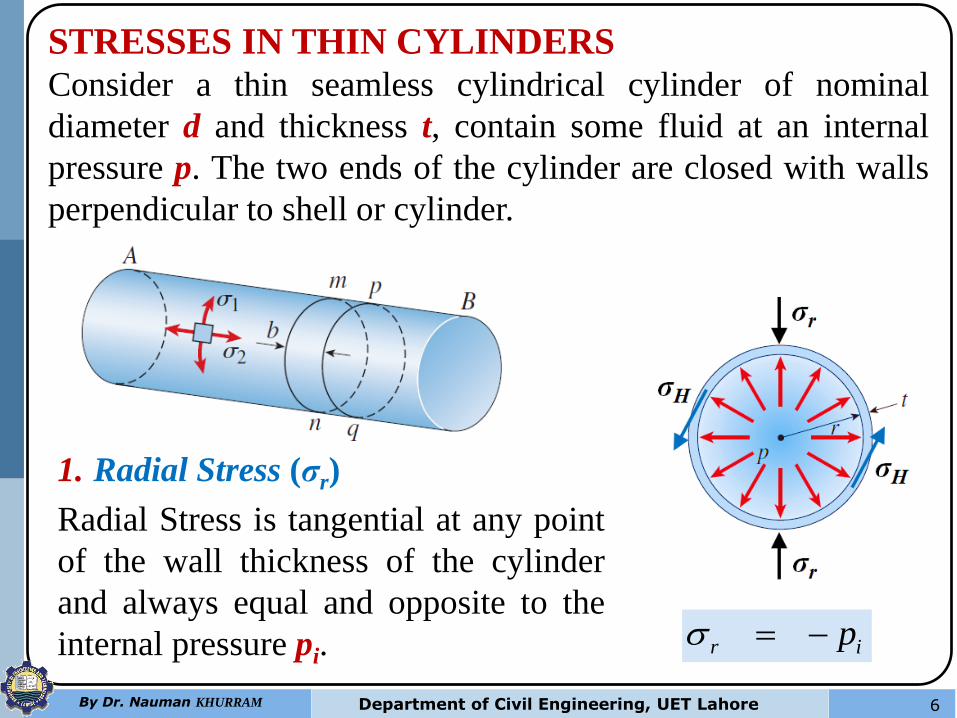
STRESSES IN THIN CYLINDERS
Consider a thin seamless cylindrical cylinder of nominal
diameter d and thickness t, contain some fluid at an internal
pressure p. The two ends of the cylinder are closed with walls
perpendicular to shell or cylinder.
1. Radial Stress (σr)
Radial Stress is tangential at any point
of the wall thickness of the cylinder
and always equal and opposite to the
internal pressure pi. ir p
7 By Dr. Nauman KHURRAM Department of Civil Engineering, UET Lahore
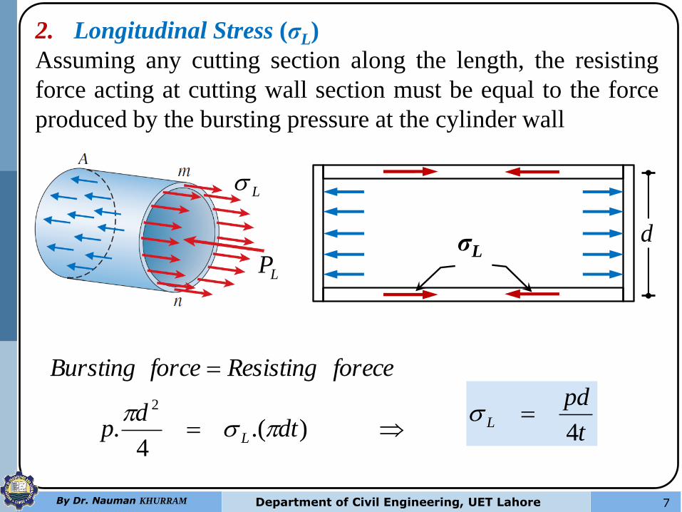
2. Longitudinal Stress (σL)
Assuming any cutting section along the length, the resisting
force acting at cutting wall section must be equal to the force
produced by the bursting pressure at the cylinder wall
LP
L
dσL
).(4
.2
dtd
p
foreceResistingforceBursting
L
t
pdL
4
8 By Dr. Nauman KHURRAM Department of Civil Engineering, UET Lahore
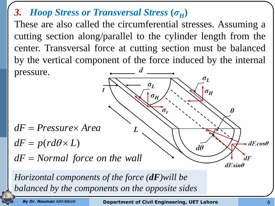
3. Hoop Stress or Transversal Stress (σH)
These are also called the circumferential stresses. Assuming a
cutting section along/parallel to the cylinder length from the
center. Transversal force at cutting section must be balanced
by the vertical component of the force induced by the internal
pressure.
walltheonforceNormaldF
LrdpdF
AreaPressuredF
)(
Horizontal components of the force (dF)will be
balanced by the components on the opposite sides
9 By Dr. Nauman KHURRAM Department of Civil Engineering, UET Lahore
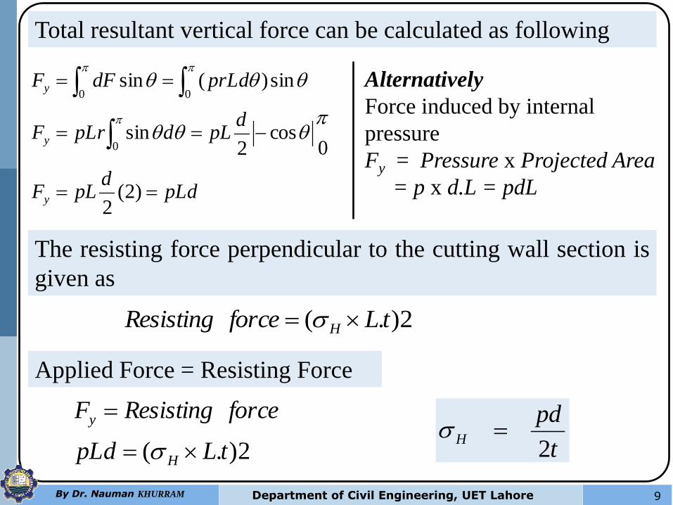
Total resultant vertical force can be calculated as following
pLdd
pLF
dpLdpLrF
prLddFF
y
y
y
)2(2
0cos
2sin
sin)(sin
0
00
2).( tLforceResisting H
The resisting force perpendicular to the cutting wall section is
given as
Applied Force = Resisting Force
2).( tLpLd
forceResistingF
H
y
t
pdH
2
Alternatively
Force induced by internal
pressure
Fy = Pressure x Projected Area
= p x d.L = pdL
10 By Dr. Nauman KHURRAM Department of Civil Engineering, UET Lahore
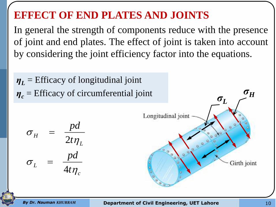
EFFECT OF END PLATES AND JOINTS
In general the strength of components reduce with the presence
of joint and end plates. The effect of joint is taken into account
by considering the joint efficiency factor into the equations.
σL
σH
c
L
L
H
t
pd
t
pd
4
2
ƞL = Efficacy of longitudinal joint
ƞc = Efficacy of circumferential joint
11 By Dr. Nauman KHURRAM Department of Civil Engineering, UET Lahore
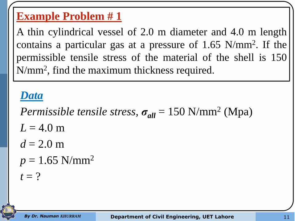
Example Problem # 1
A thin cylindrical vessel of 2.0 m diameter and 4.0 m length
contains a particular gas at a pressure of 1.65 N/mm2. If the
permissible tensile stress of the material of the shell is 150
N/mm2, find the maximum thickness required.
Data
Permissible tensile stress, σall = 150 N/mm2 (Mpa)
L = 4.0 m
d = 2.0 m
p = 1.65 N/mm2
t = ?
12 By Dr. Nauman KHURRAM Department of Civil Engineering, UET Lahore
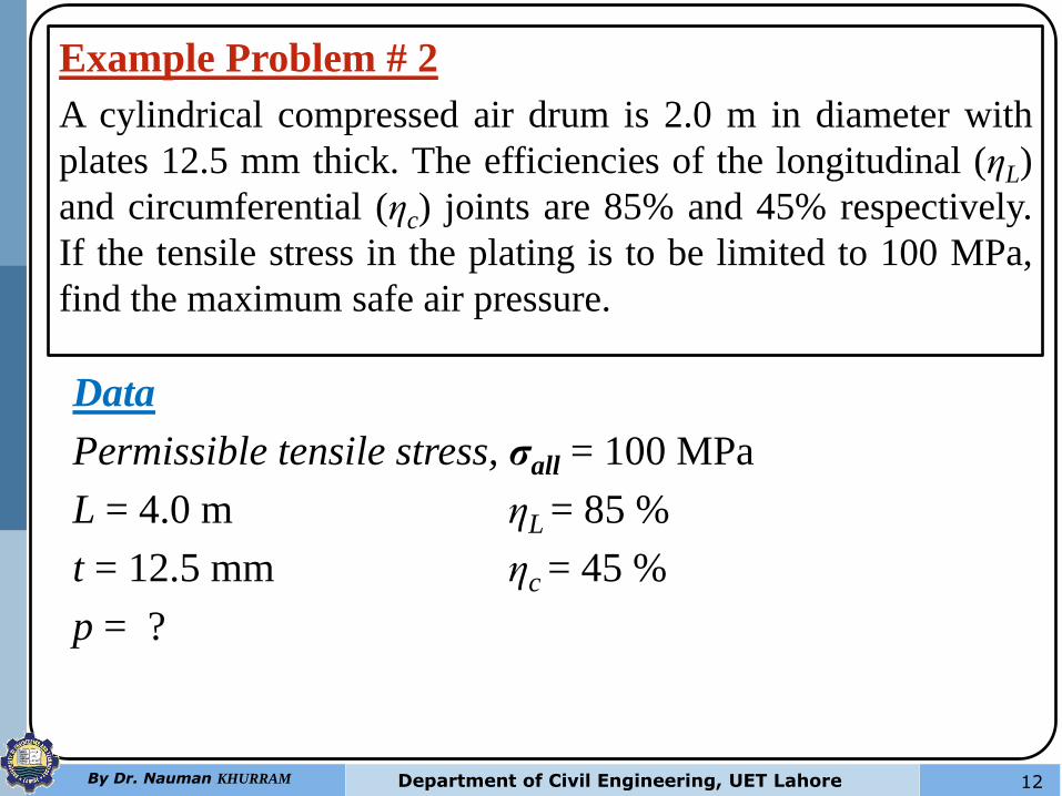
Example Problem # 2
A cylindrical compressed air drum is 2.0 m in diameter with
plates 12.5 mm thick. The efficiencies of the longitudinal (ηL)
and circumferential (ηc) joints are 85% and 45% respectively.
If the tensile stress in the plating is to be limited to 100 MPa,
find the maximum safe air pressure.
Data
Permissible tensile stress, σall = 100 MPa
L = 4.0 m ηL = 85 %
t = 12.5 mm ηc = 45 %
p = ?
13 By Dr. Nauman KHURRAM Department of Civil Engineering, UET Lahore
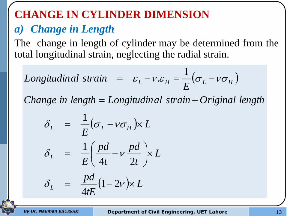
CHANGE IN CYLINDER DIMENSION
a) Change in Length
The change in length of cylinder may be determined from the total longitudinal strain, neglecting the radial strain.
LtE
pd
Lt
pd
t
pd
E
LE
lengthOriginalstrainalLongitudinlengthinChange
EstrainalLongitudin
L
L
HLL
HLHL
214
24
1
1
1.
14 By Dr. Nauman KHURRAM Department of Civil Engineering, UET Lahore
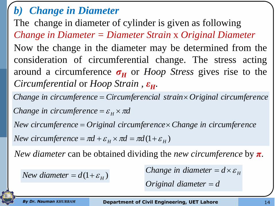
b) Change in Diameter
The change in diameter of cylinder is given as following
Change in Diameter = Diameter Strain x Original Diameter
Now the change in the diameter may be determined from the
consideration of circumferential change. The stress acting
around a circumference σH or Hoop Stress gives rise to the
Circumferential or Hoop Strain , εH.
)1( HH
H
dddncecircumfereNew
ncecircumfereinChangencecircumfereOriginalncecircumfereNew
dncecircumfereinChange
ncecircumfereOriginalstrainncialCircumferencecircumfereinChange
New diameter can be obtained dividing the new circumference by π.
)1( HddiameterNew ddiameterOriginal
ddiameterinChange H
15 By Dr. Nauman KHURRAM Department of Civil Engineering, UET Lahore
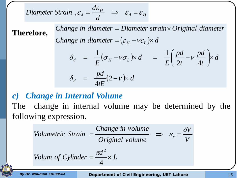
HdH
dd
dStrainDiameter
,
dtE
pd
dt
pd
t
pd
Ed
E
ddiameterinChange
diameterOriginalstrainDiameterdiameterinChange
d
LHd
LH
24
42
11
c) Change in Internal Volume
The change in internal volume may be determined by the
following expression.
Ld
CylinderofVolum
V
V
volumeOriginal
volumeinChangeStrainVolumetric v
4
2
Therefore,
16 By Dr. Nauman KHURRAM Department of Civil Engineering, UET Lahore
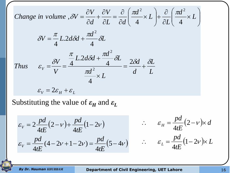
LHV
VL
L
d
d
Ld
Ld
ddL
V
VThus
Ld
ddLV
Ld
LL
d
dL
V
d
VVvolumeinChange
2
2
4
42.
4
42.
4
44,
2
2
2
22
Substituting the value of εH and εL
454
)2124(4
214
24
2
tE
pd
tE
pd
tE
pd
tE
pd
V
V
LtE
pd
dtE
pd
L
H
214
24
17 By Dr. Nauman KHURRAM Department of Civil Engineering, UET Lahore
Example Problem # 3
A cylindrical shell, 0.8 m in a diameter and 3 m long is having
10 mm wall thickness. If the shell is subjected to an internal
pressure of 2.5 N/mm2, determine
(a) change in diameter,
(b) change in length, and
(c) change in volume.
Take E = 200 GPa and Poisson’s ratio = 0.25.
Data
Diameter of the shell, d = 0.8 m = 800 mm.
Thickness of the shell, t = 10 mm.
Internal pressure, p = 2.5 N/mm2.
δd, δL and δV = ?
18 By Dr. Nauman KHURRAM Department of Civil Engineering, UET Lahore
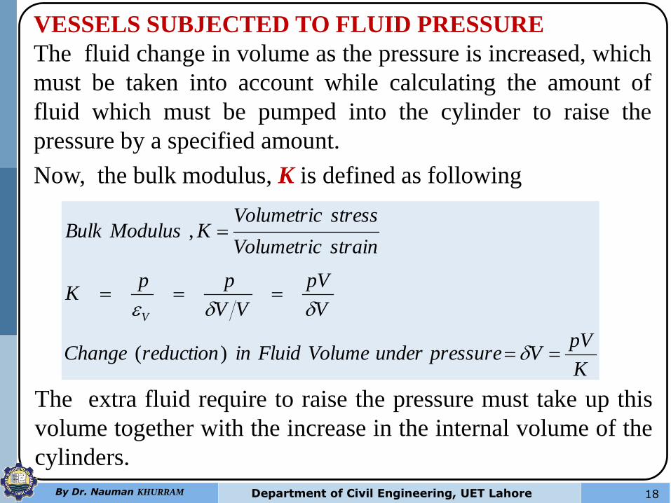
VESSELS SUBJECTED TO FLUID PRESSURE
The fluid change in volume as the pressure is increased, which
must be taken into account while calculating the amount of
fluid which must be pumped into the cylinder to raise the
pressure by a specified amount.
Now, the bulk modulus, K is defined as following
K
pVVpressureunderVolumeFluidinreductionChange
V
pV
VV
ppK
strainVolumetric
stressVolumetricKModulusBulk
V
)(
,
The extra fluid require to raise the pressure must take up this
volume together with the increase in the internal volume of the
cylinders.
19 By Dr. Nauman KHURRAM Department of Civil Engineering, UET Lahore
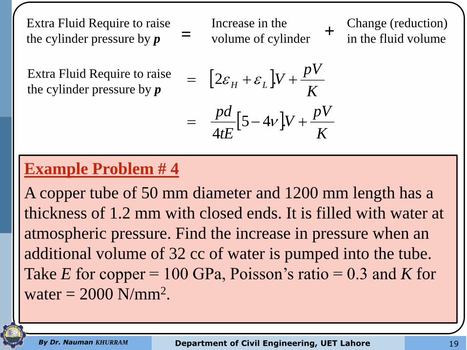
Extra Fluid Require to raise
the cylinder pressure by p
Increase in the
volume of cylinder
Change (reduction)
in the fluid volume = +
K
pVV
tE
pd
K
pVVLH
.454
.2
Extra Fluid Require to raise
the cylinder pressure by p
Example Problem # 4
A copper tube of 50 mm diameter and 1200 mm length has a
thickness of 1.2 mm with closed ends. It is filled with water at
atmospheric pressure. Find the increase in pressure when an
additional volume of 32 cc of water is pumped into the tube.
Take E for copper = 100 GPa, Poisson’s ratio = 0.3 and K for
water = 2000 N/mm2.
20 By Dr. Nauman KHURRAM Department of Civil Engineering, UET Lahore
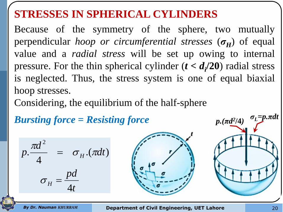
STRESSES IN SPHERICAL CYLINDERS
Because of the symmetry of the sphere, two mutually
perpendicular hoop or circumferential stresses (σH) of equal
value and a radial stress will be set up owing to internal
pressure. For the thin spherical cylinder (t < di/20) radial stress
is neglected. Thus, the stress system is one of equal biaxial
hoop stresses.
Considering, the equilibrium of the half-sphere
Bursting force = Resisting force σL=p.πdt p.(πd2/4)
t
pd
dtd
p
H
H
4
).(4
.2
21 By Dr. Nauman KHURRAM Department of Civil Engineering, UET Lahore
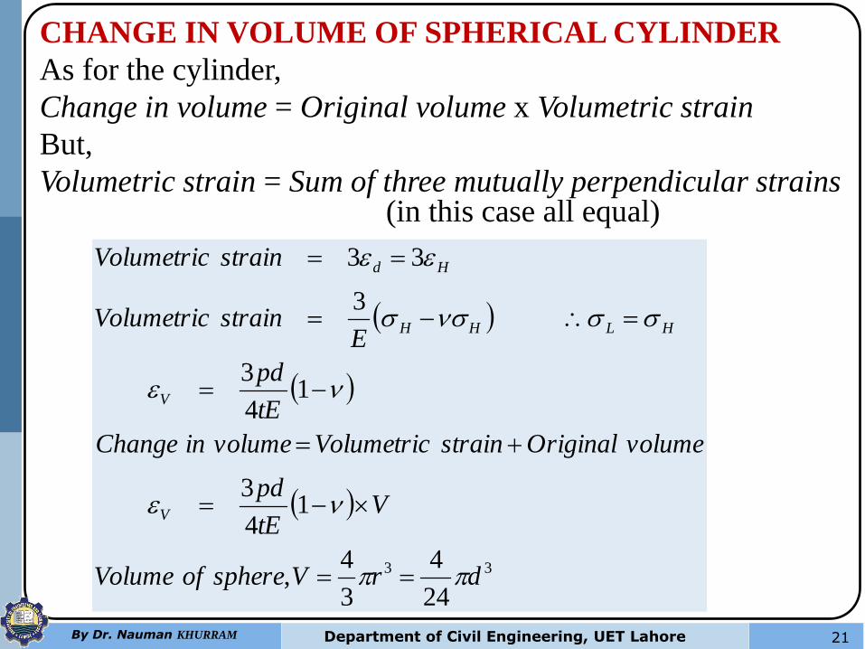
CHANGE IN VOLUME OF SPHERICAL CYLINDER
As for the cylinder,
Change in volume = Original volume x Volumetric strain
But,
Volumetric strain = Sum of three mutually perpendicular strains (in this case all equal)
33
24
4
3
4,
14
3
14
3
3
33
drVsphereofVolume
VtE
pd
volumeOriginalstrainVolumetricvolumeinChange
tE
pd
EstrainVolumetric
strainVolumetric
V
V
HLHH
Hd
22 By Dr. Nauman KHURRAM Department of Civil Engineering, UET Lahore
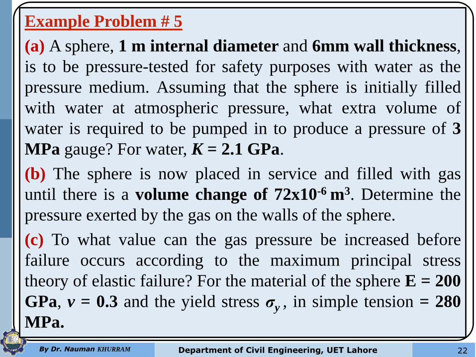
Example Problem # 5
(a) A sphere, 1 m internal diameter and 6mm wall thickness,
is to be pressure-tested for safety purposes with water as the
pressure medium. Assuming that the sphere is initially filled
with water at atmospheric pressure, what extra volume of
water is required to be pumped in to produce a pressure of 3
MPa gauge? For water, K = 2.1 GPa.
(b) The sphere is now placed in service and filled with gas
until there is a volume change of 72x10-6 m3. Determine the
pressure exerted by the gas on the walls of the sphere.
(c) To what value can the gas pressure be increased before
failure occurs according to the maximum principal stress
theory of elastic failure? For the material of the sphere E = 200
GPa, v = 0.3 and the yield stress σy , in simple tension = 280
MPa.
Thick Cylinders
By Dr. Nauman KHURRAM Department of Civil Engineering, UET Lahore 23
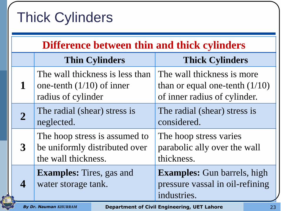
Difference between thin and thick cylinders
Thin Cylinders Thick Cylinders
1 The wall thickness is less than
one-tenth (1/10) of inner
radius of cylinder
The wall thickness is more
than or equal one-tenth (1/10)
of inner radius of cylinder.
2 The radial (shear) stress is
neglected.
The radial (shear) stress is
considered.
3 The hoop stress is assumed to
be uniformly distributed over
the wall thickness.
The hoop stress varies
parabolic ally over the wall
thickness.
4 Examples: Tires, gas and
water storage tank.
Examples: Gun barrels, high
pressure vassal in oil-refining
industries.
24 By Dr. Nauman KHURRAM Department of Civil Engineering, UET Lahore
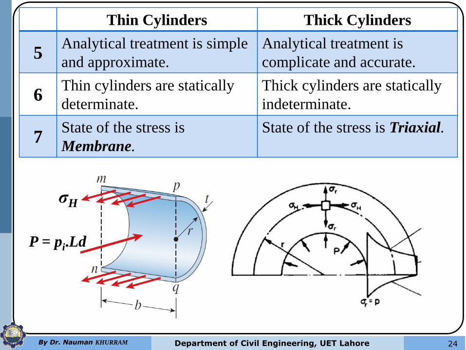
Thin Cylinders Thick Cylinders
5 Analytical treatment is simple
and approximate.
Analytical treatment is
complicate and accurate.
6 Thin cylinders are statically
determinate.
Thick cylinders are statically
indeterminate.
7 State of the stress is
Membrane.
State of the stress is Triaxial.
L
σH
P = pi.Ld
25 By Dr. Nauman KHURRAM Department of Civil Engineering, UET Lahore
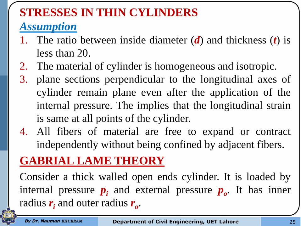
STRESSES IN THIN CYLINDERS
Assumption
1. The ratio between inside diameter (d) and thickness (t) is
less than 20.
2. The material of cylinder is homogeneous and isotropic.
3. plane sections perpendicular to the longitudinal axes of
cylinder remain plane even after the application of the
internal pressure. The implies that the longitudinal strain
is same at all points of the cylinder.
4. All fibers of material are free to expand or contract
independently without being confined by adjacent fibers.
GABRIAL LAME THEORY
Consider a thick walled open ends cylinder. It is loaded by
internal pressure pi and external pressure po. It has inner
radius ri and outer radius ro.
26 By Dr. Nauman KHURRAM Department of Civil Engineering, UET Lahore
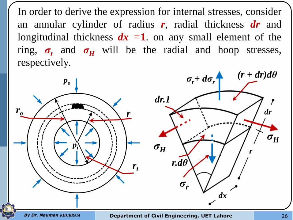
In order to derive the expression for internal stresses, consider
an annular cylinder of radius r, radial thickness dr and
longitudinal thickness dx =1. on any small element of the
ring, σr and σH will be the radial and hoop stresses,
respectively.
pi
po
ro r
ri
σH
dr
σH
σr
(r + dr)dθ
dr.1
r.dθ
r
dx
σr+ dσr
27 By Dr. Nauman KHURRAM Department of Civil Engineering, UET Lahore
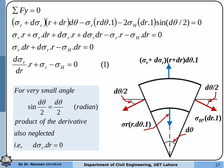
)1(0.
0...
0.....
0)2/sin(1.21.
0
Hrr
Hrr
Hrrrrr
Hrrr
rdr
d
drrddr
drrdrdrddrr
ddrrdddrrd
Fy
σH.(dr.1)
dθ σr(r.dθ.1)
(σr+ dσr)(r+dr)dθ.1
dθ/2 dθ/2
0.,.
)(22
sin
drdei
neglectedalso
derivativetheofproduct
radiandd
anglesmallveryFor
r
28 By Dr. Nauman KHURRAM Department of Civil Engineering, UET Lahore
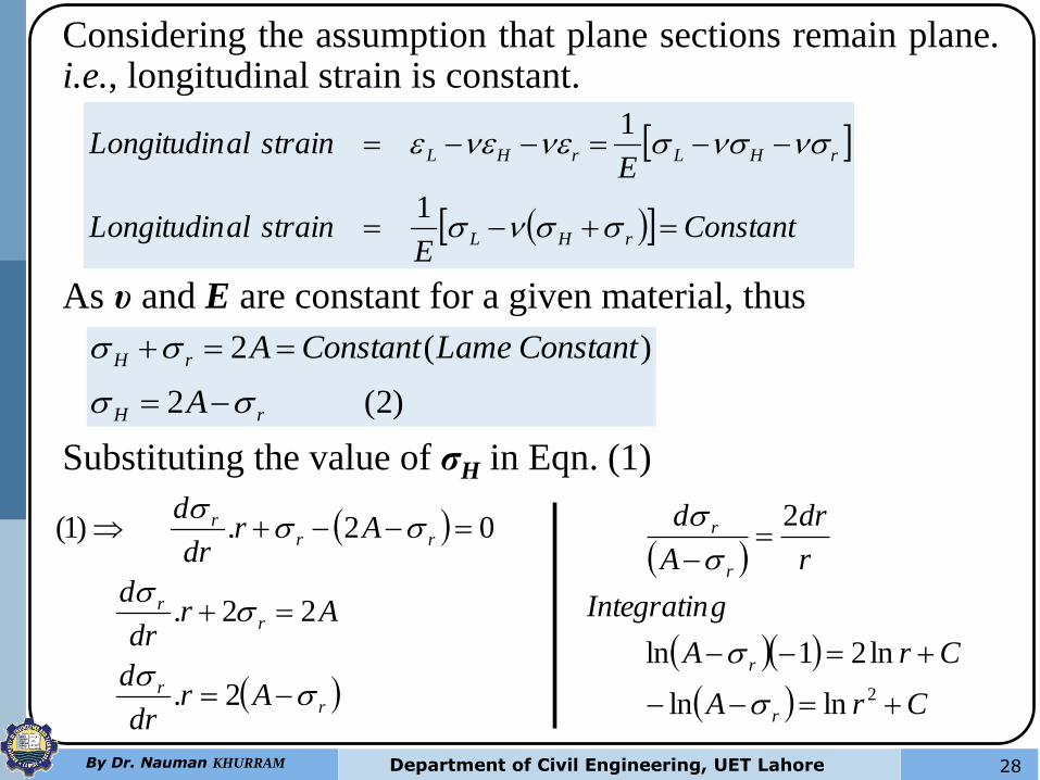
Considering the assumption that plane sections remain plane. i.e., longitudinal strain is constant.
ConstantE
strainalLongitudin
EstrainalLongitudin
rHL
rHLrHL
1
1
As υ and E are constant for a given material, thus
)2(2
)(2
rH
rH
A
ConstantLameConstantA
Substituting the value of σH in Eqn. (1)
rr
rr
rrr
Ardr
d
Ardr
d
Ardr
d
2.
22.
02.)1(
CrA
CrA
gIntegratin
r
dr
A
d
r
r
r
r
2lnln
ln21ln
2
29 By Dr. Nauman KHURRAM Department of Civil Engineering, UET Lahore
xe
axx
erA
CrA
CrA
CrA
gIntegratin
r
dr
A
d
a
e
C
r
r
r
r
r
r
logln
ln
lnln
ln21ln
2
2
2
2
)4(
)2(
)3(
logln
2
2
2
r
BA
r
BA
BrA
Bconstante
Let
xeaxx
H
r
r
C
a
e
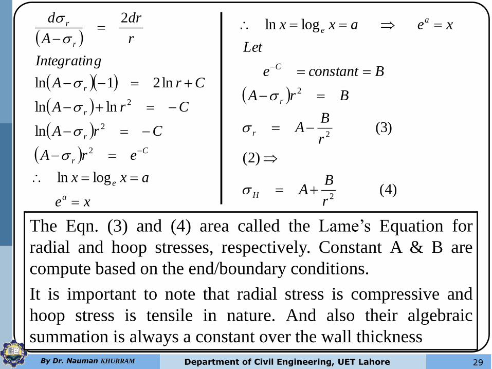
The Eqn. (3) and (4) area called the Lame’s Equation for
radial and hoop stresses, respectively. Constant A & B are
compute based on the end/boundary conditions.
It is important to note that radial stress is compressive and
hoop stress is tensile in nature. And also their algebraic
summation is always a constant over the wall thickness
30 By Dr. Nauman KHURRAM Department of Civil Engineering, UET Lahore
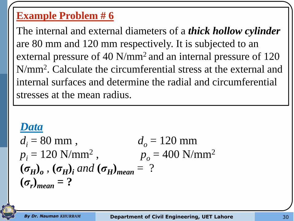
Example Problem # 6
The internal and external diameters of a thick hollow cylinder
are 80 mm and 120 mm respectively. It is subjected to an
external pressure of 40 N/mm2 and an internal pressure of 120
N/mm2. Calculate the circumferential stress at the external and
internal surfaces and determine the radial and circumferential
stresses at the mean radius.
Data
di = 80 mm , do = 120 mm
pi = 120 N/mm2 , po = 400 N/mm2
(σH)o , (σH)i and (σH)mean = ?
(σr)mean = ?
31 By Dr. Nauman KHURRAM Department of Civil Engineering, UET Lahore
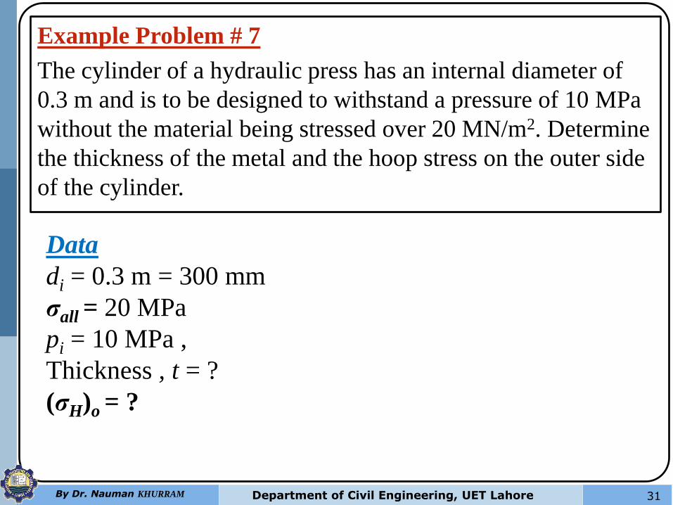
Example Problem # 7
The cylinder of a hydraulic press has an internal diameter of
0.3 m and is to be designed to withstand a pressure of 10 MPa
without the material being stressed over 20 MN/m2. Determine
the thickness of the metal and the hoop stress on the outer side
of the cylinder.
Data
di = 0.3 m = 300 mm
σall = 20 MPa
pi = 10 MPa ,
Thickness , t = ?
(σH)o = ?